

Page 1
Bulletin 71.3:Y696VR
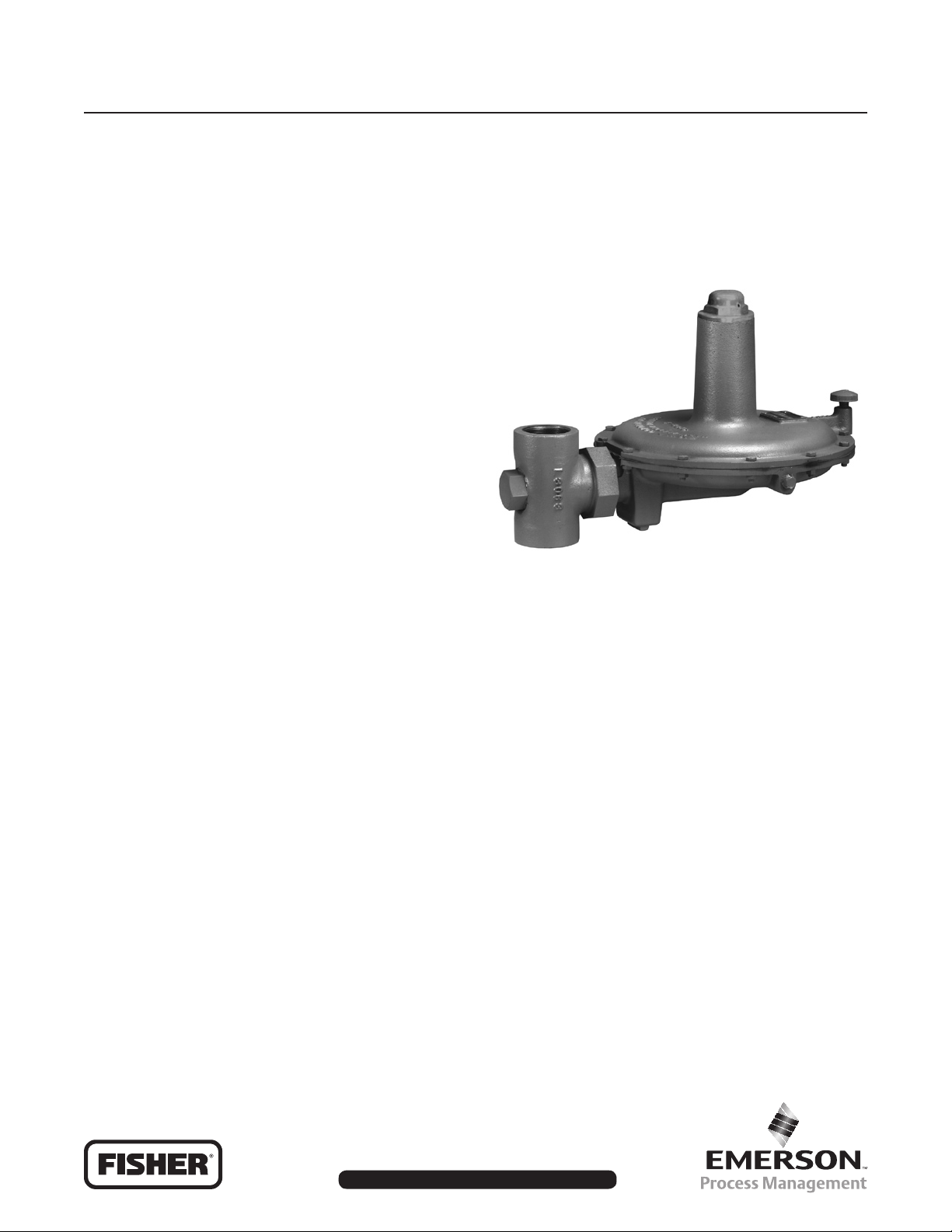
Y696VR Series Vacuum Regulator
Introduction
The Y696VR Series are direct-operated vacuum
regulators used where a decrease in vacuum
(increase in absolute pressure) must be limited, such
as between a tank and vacuum source to control
vacuum in the tank. The Type Y696VR has internal
pressure registration. The Type Y696VRM has a
control line connection port and blocked throat for
external pressure registration.
Features
• Precision Control of Low Pressure Settings—
Large diaphragm areas provide more accurate
control at low pressure settings.
• Installation Adaptability—Four-position vent
mounting and 360° adjustability of the union
nut connection permit exibility in vent positioning
and installation in awkward positions or
limited spaces.
• Corrosion Resistance—Constructions are
available in a variety of materials for compatibility
with corrosive process gases.
Principle of Operation
A vacuum regulator maintains a constant vacuum at
the regulator inlet. A decrease in vacuum (increase
in absolute pressure) below the setpoint registers
on the diaphragm and opens the disk. This allows
the pressure from the higher vacuum source to pass
through the regulator and restore the vacuum to its
original setting. On the Type Y696VR, the controlled
pressure registers directly into the diaphragm casing.
The Type Y696VRM has a control line connecting the
diaphragm casing to the vacuum being controlled and
an O-ring stem seal blocking the throat allowing for
registration only through the control line connection.
W7431
Figure 1. Type Y696VR Vacuum Regulator
Installation
The versatility of the Y696VR Series devices permits
a wide variety of installations. The body may be
mounted in any position (360° rotation possible) relative
to the spring and diaphragm cases just by loosening
the union nut and rotating the diaphragm case. Spring
case can be rotated to t the application required. Any
mounting position provides excellent performance.
When exposed to the weather, spring case port should
be protected by an optional umbrella vent or pointed
downward to allow drainage. When indoors, pipe this
port outside if used in hazardous gas service.
Downstream piping will vary with the installation. To
obtain the calculated characteristics, piping should be
the same size as the outlet and straight for the rst
18-inches (457 mm).
November 2008
www.emersonprocess.com/regulators
D102664X012
Page 2
Bulletin 71.3:Y696VR
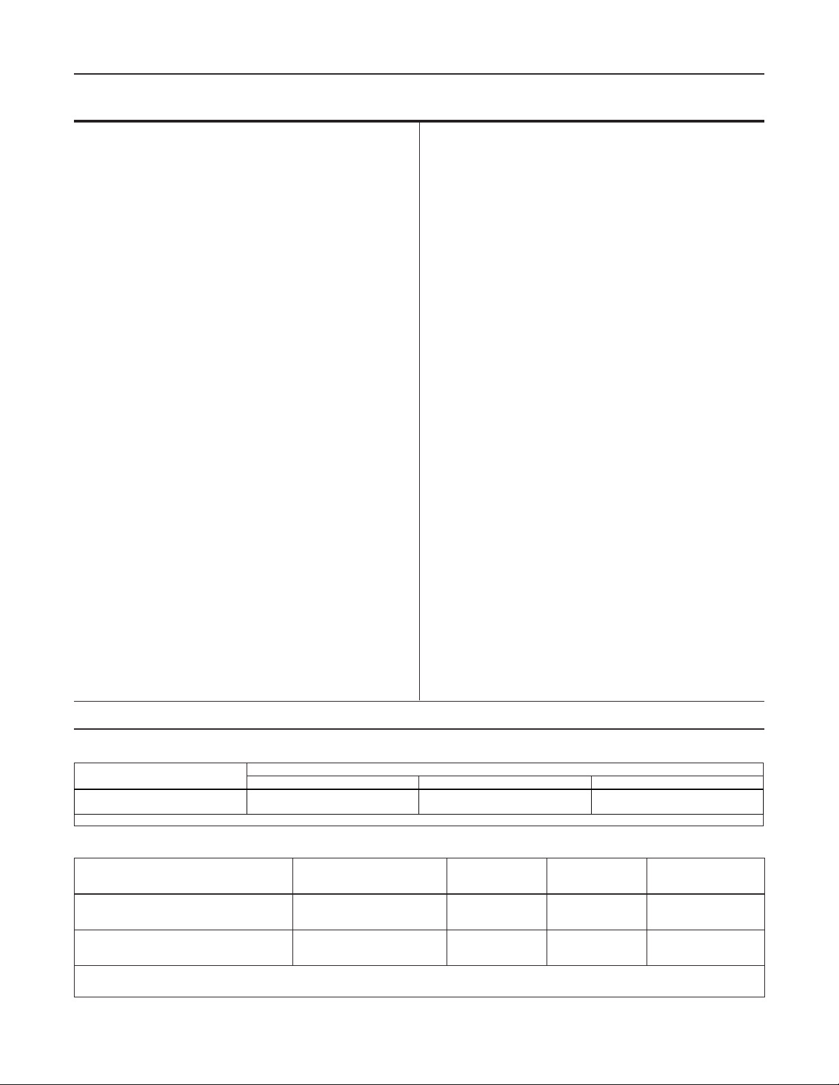
Specications
Body Sizes and End Connection Styles
See Table 1
Maximum Allowable Emergency Inlet
(Casing) Pressure
(2)
±15 psig (±1,03 bar)
Maximum Allowable Pressure without Internal
Parts Damage
(2)
±8 psig (±0,55 bar)
Maximum Downstream Pressure
(2)
Full Vacuum
(1)
Material Temperature Capabilities
Nitrile (NBR): -40° to 180°F (-40° to 82°C)
Fluorocarbon (FKM): 40° to 300°F (4° to 149°C)
Ethyleneproplyene (EPR):
-20° to 200°F (-29° to 93°C)
Peruoroelastomer (FFKM):
0° to 300°F (-18° to 149°C)
Silicone (VMQ): -40° to 400°F (-40° to 204°C)
Construction Materials
Body: Cast iron, WCC steel (NACE), CF8M
Stainless steel (NACE), or Hastelloy C (optional)
Diaphragm Casing: Cast iron, WCC steel (NACE),
Wide-Open Flow Coefcients
Cg: 515; Cv: 14.7; C1: 35
Vacuum Control Pressure Ranges
(1)
See Table 2
Capacities
See Table 3
Spring Case Connection
3/4-inch NPT
Control Line Connection
1/2-inch NPT
CF8M Stainless steel, or Hastelloy C (optional)
Spring Case: Cast iron, WCC steel, aluminum, or
CF8M Stainless steel
Disk Holder: 302 Stainless steel (standard) or
316 Stainless steel (NACE)
Disk: Nitrile (NBR) or Fluorocarbon (FKM)
(standard); Neoprene (CR), Polytetrauoroethylene
(PTFE), Fluorocarbon (FKM), Peruoroelastomer
(FFKM), or Ethylenepropylene (EPR) (NACE)
Diaphragm: Nitrile (NBR), Fluorocarbon (FKM),
Ethylenepropylene (EPR), or Silicone
Trim: 302 stainless steel (standard), 316 Stainless
steel (NACE), or Hastelloy C (optional)
Gauge Tap Connection
1/4-inch NPT
Pressure Registration
Type Y696VR: Internal
Type Y696VRM: External
O-rings: Nitrile (NBR), Fluorocarbon (FKM),
Peruoroelastomer (FFKM), or
Ethylenepropylene (EPR)
Approximate Weights
Cast Iron: 45 pounds (20,4 kg)
Steel, Stainless Steel, or Hastelloy C:
57 pounds (25,9 kg)
(2)
1. End connections for other than U.S. standards can usually be provided; consult the local Sales Ofce.
2. The pressure/temperature limits in this bulletin and any applicable standard or code limitation should not be exceeded.
Table 1. Body Sizes and End Connection Styles
BODY SIZE,
INCHES (DN)
1-1/2 (40)
2 (50)
1. All anges are welded on to the body and have a face-to-face dimension of 14-inches (356 mm).
Cast Iron Steel or Stainless Steel Hastelloy C
CONSTRUCTION MATERIAL AND END CONNECTION STYLE
NPT
NPT, SWE, CL150 RF, CL300 RF, or
PN 16/25/40
Table 2. Vacuum Control Pressure Ranges and Spring Part Numbers
VACUUM CONTROL
PRESSURE RANGE
1 to 3-inches w.c.
1-1/2 to 5-inches w.c.
3 to 8-inches w.c.
8 to 16-inches w.c.
16 to 32-inches w.c.
1. Pressure ranges are based on the spring case pointing up. Pointing the spring case down increases the pressure range 1.7-inches w.c. (4,2 mbar).
(Example: 1 to 3-inches w.c. (2,5 to 7,5 mbar) changes to 2.7 to 4.7-inches w.c. (6,7 to 11,7 mbar).)
2. Do not use Fluorocarbon (FKM) diaphragm with these springs at diaphragm temperatures lower than 40°F (4°C).
2
0.25 to 3 psig
(1)
(2 to 7 mbar)
(4 to 12 mbar)
(7 to 20 mbar)
(20 to 40 mbar)
(40 to 80 mbar)
(17 to 207 mbar)
(2)
(2)
(2)
CHANGE IN VACUUM
CONTROL PRESSURE TO
REACH WIDE-OPEN
1.5-inches w.c.
2-inches w.c.
3-inches w.c.
4-inches w.c.
7-inches w.c.
1.2 psig
(4 mbar)
(5 mbar)
(7 mbar)
(10 mbar)
(17 mbar)
(83 mbar)
SPRING PART
NUMBER
1D892527022
1D7654000A2
0B019727052
1B766627062
1B883327022
1A630627022
SPRING COLOR
Brown
Unpainted
Purple
Gray
Unpainted
Black
(1)
CL150 RF
0.109-inch
0.120-inch
0.148-inch
0.156-inch
0.187-inch
0.275-inch
SPRING WIRE
DIAMETER
(2,77 mm)
(3,05 mm)
(3,76 mm)
(3,96 mm)
(4,75 mm)
(6,99 mm)
Page 3

Capacity Information
Bulletin 71.3:Y696VR
To determine ow capacities for the Y696VR Series vacuum
regulators, use the following formula:
Q = P
3415
SIN DEG
1abs Cg
C
P
P
1
1abs
where,
Q = ow capacity in SCFH (60°F, 14.7 psia) of air
P
= absolute inlet pressure, psia (P1 psig + 14.7)
1abs
Cg = ow coefcient
C1 = 35
P = pressure drop across the vacuum breaker
If the actual change in control pressure (from the service
conditions) is less than the change in vacuum control
pressure required to reach wide-open (Table 2), the Cg in
the formula must be reduced accordingly. To reduce Cg,
multiply Cg (515) by the ratio of the actual change in control
pressure to the change in vacuum control pressure required
to reach wide-open.
Conversion Factors
To determine equivalent capacities of other common gases,
multiply the calculated capacity by the following appropriate
conversion factor: natural gas–1.29, propane–0.810,
butane–0.707, or nitrogen–1.018. For gases of other
specic gravities, divide by the square root of the appropriate
specic gravity.
GAUGE TAP
1/4-INCH NPT
VACUUM BEING
CONTROLLED
HIGHER VACUUM SOURCE
VACUUM
PUMP
INLET PRESSURE
OUTLET PRESSURE
ATMOSPHERIC PRESSURE
Figure 2. Type Y696VR Operational Schematic
5.19
(132)
17.44
(443)
Figure 3. Y696VR Series Dimensions
Table 3. Y696VR Series Capacities
VACUUM CONTROL
PRESSURE RANGE
1 to 3-inches w.c.
1-1/2 to 5-inches w.c.
3 to 8-inches w.c.
8 to 16-inches w.c.
16 to 32-inches w.c.
0.25 to 3 psig
(2 to 7 mbar)
(4 to 12 mbar)
(7 to 20 mbar)
(20 to 40 mbar)
(40 to 80 mbar)
(17 to 207 mbar)
10.38
(264)
VACUUM CONTROL
PRESSURE SETTING
3-inches w.c.
5-inches w.c.
8-inches w.c.
16-inches w.c.
24-inches w.c.
2 psig
2.94 (74,7)
2.25
(57,2)
(7 mbar)
(12 mbar)
(20 mbar)
(40 mbar)
(60 mbar)
(138 mbar)
9.68
(246)
14.0
(356)
5.88
(149)
7.00
(178)
CHANGE IN VACUUM
CONTROL PRESSURE TO
REACH WIDE-OPEN
1.5-inches w.c.
2-inches w.c.
3-inches w.c.
4-inches w.c.
7-inches w.c.
1.2 psig
(4 mbar)
(5 mbar)
(7 mbar)
(10 mbar)
(17 mbar)
(83 mbar)
12.72
(323)
CAPACITIES IN SCFH
(Nm3/h) OF AIR
6953
6920
6876
6722
6612
6496
(186)
(185)
(184)
(180)
(177)
(174)
7.06
(179)
DOWNSTREAM
VACUUM
7 psig (0,48 bar)
vacuum
INCHES
(mm)
3
Page 4

Bulletin 71.3:Y696VR
Ordering Information
When ordering, specify:
Application
1. Composition and specic gravity of gas
(including chemical analysis if possible)
2. Temperature range
3. Inlet pressures (maximum, minimum, nominal)
4. Pressure drops
5. Desired pressure setting or range
6. Flow rates (minimum, maximum, normal)
7. Piping size(s)
Construction
Refer to the Specications section and to each
referenced table; specify the desired selection
whenever there is a choice to be made. Be sure to
specify spring case port location from Figure 4.
F
C
E
CJ4598-B
D
Figure 4. Spring Case Port Location
Industrial Regulators
Emerson Process Management
Regulator Technologies, Inc.
USA - Headquarters
McKinney, Texas 75069-1872 USA
Tel: 1-800-558-5853
Outside U.S. 1-972-548-3574
Asia-Pacic
Shanghai, China 201206
Tel: +86 21 2892 9000
Europe
Bologna, Italy 40013
Tel: +39 051 4190611
Middle East and Africa
Dubai, United Arab Emirates
Tel: +971 4811 8100
For further information visit www.emersonprocess.com/regulators
The Emerson logo is a trademark and service mark of Emerson Electric Co. All other marks are the property of their prospective owners. Fisher is a mark owned by Fisher Controls, Inc., a
business of Emerson Process Management.
The contents of this publication are presented for informational purposes only, and while every effort has been made to ensure their accuracy, they are not to be construed as warranties or
guarantees, express or implied, regarding the products or services described herein or their use or applicability. We reserve the right to modify or improve the designs or specications of such
products at any time without notice.
Emerson Process Management does not assume responsibility for the selection, use or maintenance of any product. Responsibility for proper selection, use and maintenance of any Emerson
Process Management product remains solely with the purchaser.
Natural Gas Technologies
Emerson Process Management
Regulator Technologies, Inc.
USA - Headquarters
McKinney, Texas 75069-1872 USA
Tel: 1-800-558-5853
Outside U.S. 1-972-548-3574
Asia-Pacic
Singapore, Singapore 128461
Tel: +65 6777 8211
Europe
Bologna, Italy 40013
Tel: +39 051 4190611
Gallardon, France 28320
Tel: +33 (0)2 37 33 47 00
TESCOM
Emerson Process Management
Tescom Corporation
USA - Headquarters
Elk River, Minnesota 55330-2445 USA
Tel: 1-763-241-3238
Europe
Selmsdorf, Germany 23923
Tel: +49 (0) 38823 31 0
©Emerson Process Management Regulator Technologies, Inc., 1999,2008; All Rights Reserved
 Loading...