

Page 1
Instruction Manual
Form 5312
January 2009
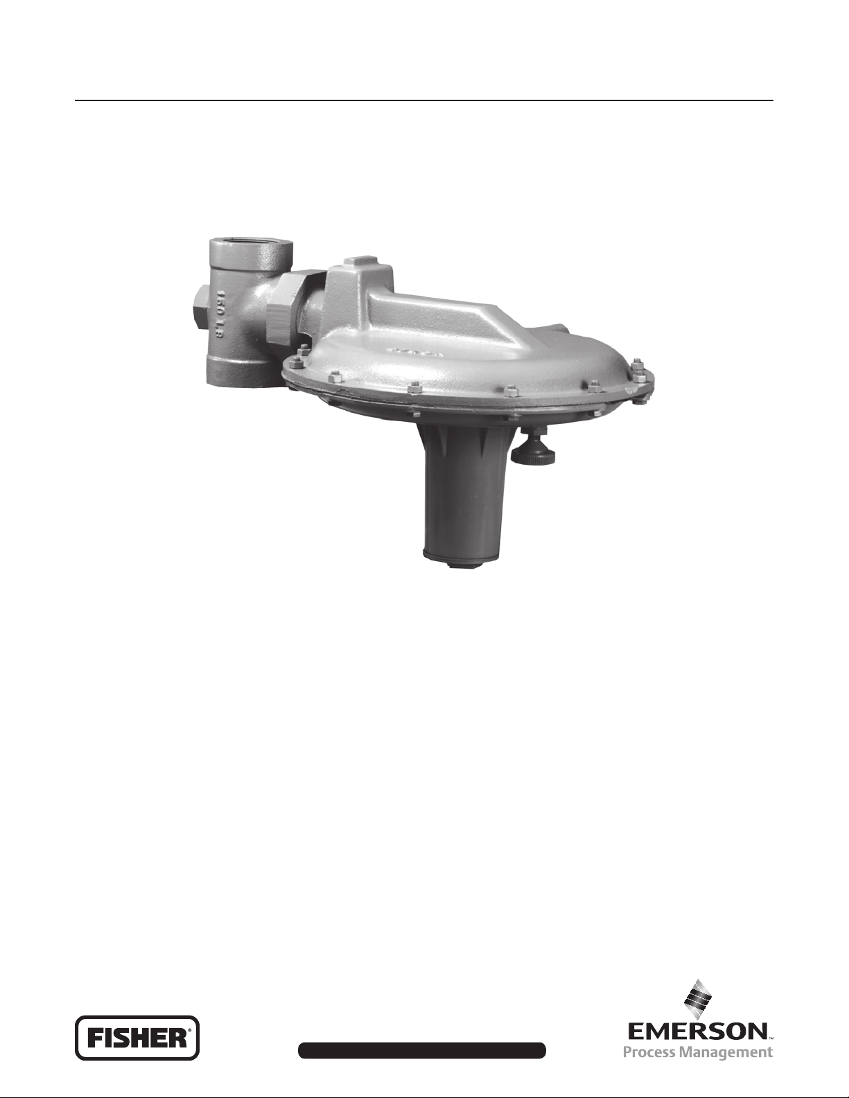
Type Y696 Vapor Recovery Regulator
Type Y696
W5996
Figure 1. Type Y696 Vapor Recovery Regulator
Introduction
Scope of Manual
This instruction manual includes installation, startup,
maintenance, and parts information for the Type Y696
vapor recovery regulator.
Product Description
The Type Y696 vapor recovery regulator is a directoperated regulator with internal registration requiring
no downstream control line. It is used to sense
increase in vessel pressure and vent excessive
internal vessel pressure to an appropriate vapor
recovery disposal or reclamations system.
Specications
The Specications section lists maximum pressures,
temperatures, and other specications. Specications
for a given regulator as it originally comes from the
factory are stamped on the spring case nameplate.
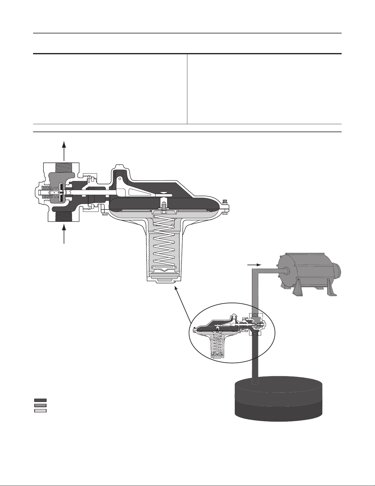
Principle of Operation
The Type Y696 is used to maintain a constant inlet
(blanket) pressure with the outlet owing to a system
whose pressure is lower than that at the inlet.
When vessel pressure increases above the setpoint
of the regulator due to pumping in or thermal heating,
the force of the control spring is overcome by
www.emersonprocess.com/regulators
D101770X012
Page 2
Type Y696
Specications
Body Size and End Connection Style
See Table 1
Maximum Allowable Inlet and Outlet Pressure
15 psig (1,0 bar)
Control Pressure Ranges
See Table 2
1. The pressure/temperature limits in this instruction manual or any applicable standard limitation should not be exceeded.
(1)
Pressure Registration
Internal
(2)
Spring Case and Vent Connections
1/4-inch NPT
Maximum Temperature Capabilities
Nitrile (NBR): -20° to 180°F (-29° to 82°C)
Fluorocarbon (FKM): 0° to 300°F (-18° to 149°C)
(2)
INLET PRESSURE
OUTLET PRESSURE
ATMOSPHERIC PRESSURE
M1058
Figure 2. Type Y696 Vapor Recovery Operational Schematic
VAPOR PRESSURE
LIQUID
VAPOR RECOVERY
VACUUM SOURCE
2
Page 3
Table 1. Body Sizes and End Connection Styles
Type Y696
BODY SIZE,
INCHES (DN)
1-1/2 and 2 (40 and 50) NPT
CONTROL PRESSURE RANGE SPRING PART NUMBER SPRING COLOR WIRE DIAMETER
2 to 5-inches w.c.
5 to 15-inches w.c.
0.3 to 1 psig
1 to 2.8 psig
2 to 3.5 psig
4 to 7 psig
1. Spring ranges based on spring case installed pointed down. When installed pointed up, spring range increases 2-inches w.c. (5 mbar).
2. Do not use Fluorocarbon (FKM) diaphragm with these springs at diaphragm temperatures lower than 60°F (16°C).
(5 to 12 mbar)
(12 to 37 mbar)
(0,02 to 0,07 bar)
(0,07 to 0,19 bar)
(0,14 to 0,24 bar)
(0,28 to 0,48 bar)
Cast Iron Steel Stainless Steel Hastelloy® C
NPT, SWE, CL150 RF,
CL300, PN 16/25/40
Table 2. Control Pressure Ranges
(1)(2)
(1)(2)
1A200127022
1B577727062
0B019427052
0A081127202
0Y066427022
1H8024000A2
pressure acting on the diaphragm. This moves the
disk away from the orice allowing gas to ow from
the vessel to the vapor recovery system.
As vessel pressure is reduced, the force of the
control spring causes the disk to move toward the
orice decreasing the ow of gas out of the vessel.
As vessel pressure drops below the setpoint of the
regulator, the disk will seat against the orice shutting
off the ow of gas.
BODY MATERIAL
NPT, SWE, CL150 RF,
CL300, PN 16/25/40
Red
Gray
Green
Orange
Green stripe
Silver
1. Use qualied personnel when installing, operating,
and maintaining the regulator. Before installing,
inspect the regulator for any shipment damage or
foreign material that may have collected during
crating and shipment. Make certain the body
interior is clean and the pipelines are free of
foreign material. Apply pipe compound only to the
male pipe threads.
2. Install the regulator using a straight run of pipe the
same size or larger as the regulator body (as
shown in Figure 2). Flow through the regulator
Installation
body is indicated by the ow arrow cast on the
body. If a block valve is required, install a full
WARNING
!
ow valve between the regulator and the
blanketed vessel. For proper operation, the
regulator should be installed with the spring case
Personal injury, equipment damage, or
leakage due to escaping accumulated gas
barrel pointed down. Key numbers referenced in
this section are shown in Figure 3.
or bursting of pressure-containing parts
may result if the vapor recovery regulator
!
is overpressured or installed where
service conditions could exceed the limits
given in the Specications section, or
where conditions exceed any ratings of
the adjacent piping or piping connections.
To avoid such injury or damage, provide
pressure-relieving or pressure-limiting
devices to prevent service conditions from
exceeding those limits.
Additionally, physical damage to the
vapor recovery regulator could result
in personal injury and property damage
due to escaping accumulated gas. To
avoid such injury and damage, install
the vapor recovery regulator in a safe
and well ventilated location.
A regulator may vent some gas to
the atmosphere. In hazardous or
ammable gas service, vented gas may
accumulate, and cause personal injury,
death, or property damage due to re or
explosion. Vent a regulator in hazardous
gas service to a remote, safe location
away from air intakes or any hazardous
location. The vent line or stack opening
must be protected against condensation
or clogging.
3. To keep the spring case vent from being plugged
or the spring case from collecting moisture,
corrosive chemicals, or other foreign material,
point the vent down or otherwise protect it.
CL150 RF
0.135-inches (3,43 mm)
0.156-inches (3,96 mm)
0.187-inches (4,75 mm)
0.250-inches (6,35 mm)
0.363-inches (9,22 mm)
0.406-inches (10,3 mm)
WARNING
3
Page 4

Type Y696
4. To remotely vent the regulator, remove the vent
(key 56) and install obstruction-free tubing or
piping into the 1/4-inch NPT vent tapping. Provide
protection on a remote vent by installing a
screened vent cap into the remote end of the
vent pipe.
5. If continuous operation of the system is required
during inspection or maintenance, install a three valve bypass around the regulator.
6. Vapor recovery regulators are used to maintain a
constant inlet (blanket) pressure with the outlet
owing to a system whose pressure is lower than
that at the inlet. The vapor recovery regulators
are not intended to be used as an ASME certied
relief device for overpressure protection. They
are to be used as part of a gas blanketing system
to control the outow of blanketing gas under
normal conditions and to collect tank vapors for
the vapor disposal or reclamation system. You
should provide alternate methods of emergency
overpressure protection.
the spring and diaphragm in the Maintenance section.
To adjust the pressure setting, perform the following
steps (key numbers are referenced in Figure 3):
1. Remove the closing cap (key 3).
2. Turn the adjusting screw (key 2) either clockwise
to increase control pressure or counterclockwise
to decrease control pressure. The regulator will
go into immediate operation. To ensure correct
operation always use a pressure gauge to
monitor the vapor recovery pressure when
making adjustments.
3. Replace the closing cap (key 3).
Shutdown
First close the nearest upstream shutoff valve and
then close the nearest downstream shutoff valve to
vent the equipment properly. Next, open the vent
valves on both the upstream and downstream sides of
the regulator. All pressure between the shutoff valves
is released through the open vent valves.
Startup and Adjustment
WARNING
!
To avoid personal injury, property
damage, or equipment damage caused
by bursting of pressure containing
parts or explosion of accumulated
gas, never adjust the control spring to
produce an outlet pressure higher than
the upper limit of the outlet pressure
range of that particular spring. If the
desired outlet pressure is not within
the range of the control spring, install
a spring of the proper range according
to the Diaphragm and Spring Case Area
section of the maintenance procedure.
With installation completed, the regulator can be
placed in operation by slowly opening the upstream
and downstream block valves, if used, while using
gauges to monitor pressure.
The regulator has been adjusted at the factory to
provide approximately the pressure requested. The
range of allowable pressure settings is stamped on the
spring casing nameplate. If a pressure setting beyond
the stamped range is required, install a spring with the
desired range by following the procedures for changing
Maintenance
Regulator parts are subject to normal wear and
must be inspected and replaced as necessary. The
frequency of inspection and replacement of parts
depends upon the severity of service conditions
or the requirements of local, state, and federal
regulations. Due to the care Fisher® takes in meeting
all manufacturing requirements (heat treating,
dimensional tolerances, etc.), use only replacement
parts manufactured or furnished by Fisher.
Key numbers are referenced in Figure 3.
WARNING
!
To avoid personal injury, property damage,
or equipment damage caused by sudden
release of pressure, isolate the regulator
from all pressure and cautiously release
trapped pressure from the regulator
before attempting disassembly.
Body Area
This procedure is for gaining access to the disk
assembly, orice, body gasket, and split ring. All
pressure must be released from the regulator, before
the following steps can be performed.
4
Page 5

Type Y696
1. To inspect and replace the disk assembly (key 25)
or orice (key 27), remove the body cap assembly
(key 38).
2. Remove the disk screw (key 47) and cotter pin
(key 14) from the disk shutoff stem (key 40) if it is
necessary to replace the disk assembly (key 25).
3. To inspect and replace the orice (key 27), loosen
the union nut (key 19) and separate the diaphragm
case assembly from the body (key 28).
4. Remove and inspect the body gasket (key 16).
5. Inspect and replace the orice (key 27) if necessary.
Lubricate the threads of the replacement orice with
a good grade of pipe thread sealant. Install and
tighten using 75 to 100 foot-pounds (102 to 136 N•m)
of torque.
6. If necessary, install the replacement body gasket
(key 16) into the body (key 28).
7. Slide the union nut (key 19) as far as it will go
onto the lower casing assembly (key 20). Install
both halves of the split ring (key 17) into the slots
of the lower casing assembly (key 20) and secure
them by sliding the union nut down on the split ring.
To Change the Control Spring:
1. Remove the closing cap (key 3), and turn the
adjusting screw (key 2) counterclockwise until all
compression is removed from the control spring
(key 1).
2. Remove the adjusting screw (key 2) and the upper
spring seat (key 44) and change the control spring
to match the desired spring range.
3. Replace the upper spring seat (key 44) and the
adjusting screw (key 2).
4. Install a replacement closing cap gasket (key 35),
if necessary, and reinstall the closing cap (key 2).
5. If the spring range was changed, be sure to
change the stamped spring range on the spring
case nameplate.
To Maintain Diaphragm Parts:
1. Remove the closing cap (key 3), and the adjusting
screw (key 2).
2. Remove the hex nuts (key 22), cap screws
(key 21) and spring case (key 23).
Note
In the following step, be sure to install
the spring case barrel pointed down as
shown in Figure 1.
8. Install the lower casing assembly (key 20) by
tightening the union nut (key 19) until the lower
casing assembly is secure on the body (key 28).
9. Install the disk spring (key 41) and disk assembly
(key 25) and secure it to the disk stem (key 40)
with the cotter pin (key 14). Install the disk screw
(key 47).
10. Use a good quality thread sealer when replacing
the body cap assembly (key 38).
Diaphragm and Spring Case Area
This procedure is for gaining access to the control
spring, diaphragm, and lever assembly stem. All
pressure must be released from the diaphragm case
assembly before the following steps can be performed.
3. Lift the upper spring seat (key 44), and control
spring (key 1) off the diaphragm and plate
assembly (key 5).
4. Remove the diaphragm and plate assembly (key 5)
by tilting them so that the pusher post (key 8) slips
off the lever assembly (key 9).
5. To separate the diaphragm assembly (key 5) from
the attached parts, unscrew the cap screw
(key 30) from the pusher post (key 8).
6. To replace the lever assembly (key 9), remove
the machine screws (key 11). To replace the stem
(key 13) pull the stem (key 13) out of the lower
casing assembly (key 20).
7. Install the stem (key 13) into the lower casing
assembly (key 20).
8. Install the lever assembly (key 9) into the stem
(key 13) and secure the lever assembly (key 9)
with the machine screws (key 11).
9. During the assembly procedure, use lubricants on
parts as indicated in Figure 3 and replace parts
as required.
5
Page 6

Type Y696
10. Install the parts on the pusher post in the order
listed below:
• Diaphragm plate gasket (key 7)
• Lower diaphragm plate (key 6)
• Diaphragm and plate assembly (key 5) pattern
side up
• Control spring seat (key 4)
11. Insert and tighten the diaphragm cap screw
(key 30) to secure the diaphragm parts to the
pusher post (key 8).
12. Install the assembled parts in the lower casing
(key 20). Make sure that the lever (key 9) ts
in the pusher post (key 8) and that the holes in
the diaphragm align with the holes in the
lower casing.
13. Install the spring case (key 23) on the lower
casing assembly (key 20) so that the vent
assembly (key 56) is correctly oriented, and
secure with the cap screws (key 21) and hex
nuts (key 22) ngertight only.
14. Place the spring (key 1) in the spring case
assembly (key 23), then install the upper spring
seat (key 44) and the adjusting screw (key 2).
15. Turn the adjusting screw (key 2) clockwise until
there is enough control spring (key 1) force to
provide proper slack to the diaphragm (key 5).
Using a crisscross pattern, nish tightening the
cap screws (key 21) and hex nuts (key 22) to
15 to 20 foot-pounds (20 to 27 N•m) of torque.
To adjust the outlet pressure to the desired setting,
refer to the Startup and Adjustment section.
16. Install a replacement closing cap gasket (key 35)
if necessary, and then install the closing cap
(key 3).
Parts Ordering
When contacting your local Sales Ofce about this
regulator, include the type number and all other
pertinent information stamped on the nameplate.
Specify the complete 11-character part number from the
following parts list when ordering replacement parts.
Parts List
In this parts list, parts marked NACE are intended
for corrosion-resistant service as detailed in the
NACE International Standards MR0175
and MR0103.
Type Y696 Regulator (Figure 3)
Key Description Part Number
1 Control Spring, Plated steel See Table 2
2 Adjusting Screw, Zinc 1A5896X0022
3 Closing Cap
Zinc 1A589544022
Steel 1J880124092
4 Lower Control Spring Seat, Zinc 0X014744012
5* Diaphragm
Nitrile (NBR) 0R032502072
Fluorocarbon (FKM) 0R0325X0032
6 Lower Diaphragm Plate
Stainless steel 0V003935032
Stainless steel (NACE) 0V0039X0022
7 Diaphragm Plate Gasket, Composition 1A348704022
8 Pusher Post, Stainless steel (NACE) 0Y096435072
9 Lever Assembly
Stainless steel 1E3409000B2
Stainless steel (NACE) 1E3409X0012
11 Machine Screw (2 required)
Stainless steel 1A866935032
Stainless steel (NACE) 1A8669X0012
13 Stem
Stainless steel 1A630935032
Stainless steel (NACE) 1A630935032
14* Cotter Pin
Stainless steel 1A866537022
Stainless steel (NACE) 1A8665X00A2
16* Body Gasket, Composition 1A348004032
17 Split Ring, Zinc-plated steel 0Y095828982
19 Union Nut
Cast iron 0Z0176X0032
Steel 0Z017624092
Stainless steel 0Z0176X0012
20 Lower Casing
Cast iron 3B973519012
Steel 3F191622012
Stainless steel 3F191633092
21 Diaphragm Case Cap Screw,
Plated steel (12 required) 1B596124052
22 Hex Nut, Zinc-plated steel (12 required) 1A309324122
23 Spring Case
Cast iron 2B155719042
Steel 34B2157X012
Stainless steel 34B2157X022
24 Diaphragm Plate
Up to 1.25 psig (0,09 bar) setpoint 0B006628982
Over 1.25 psig (0,09 bar) setpoint 1A347825022
*Recommended spare part.
6
Page 7

Type Y696
A
A
29
56
50
75
51
SECTION A-A
5
21
22
24
4
6
7
8
3
9
20
2
13
11
35
19
17
1
16
28
30
27
46
41
43B0679
47
14
40
23
25
38
Figure 3. Type Y696 Assembly
7
Page 8

Type Y696
Key Description Part Number
25* Disk Assembly
Stainless Steel Disk Holder with
Nitrile (NBR) disk 1D6405X0202
Nitrile (NBR) disk (NACE) 1D6405X0202
Fluorocarbon (FKM) disk (NACE) 1D6405X0212
27 Orice
Stainless steel 0L025335032
Stainless steel (NACE) 0L0253X0042
28 Body
NPT
Cast iron
1-1/2-inch size 1B403419012
2-inch size 1B403519012
Steel
1-1/2-inch size 2P2573X0022
1-1/2-inch size (NACE) 2P2573X0032
Stainless steel
1-1/2-inch size 2P2573X0012
CL150 RF anged
Steel
1-1/2-inch (DN 40) size (NACE) 22B4316X022
2-inch (DN 50) size 22B9226X022
Stainless steel
1-1/2-inch size (DN 40) (NACE) 22B4316X012
2-inch (DN 50) size 22B9226X012
*Recommended spare part.
Key Description Part Number
29 Pipe Plug, Zinc-plated steel 1C333528992
30 Diaphragm Cap Screw, Plated steel 1C473224052
35* Closing Cap Gasket, Neoprene (CR) 1N446206992
38 Body Cap Assembly
Stainless steel 15A2185X022
Stainless steel (NACE) 15A2185X012
40 Disk Shutoff Stem
Stainless steel 0L025135032
Stainless steel (NACE) 0L0251X0022
41 Disk Spring
Stainless steel
Up to 1.25 psig (0,09 bar) setpoint 1A866837022
Over 1.25 psig (0,09 bar) setpoint 0D002827022
Stainless steel (NACE)
Up to 1.25 Psig (0,09 bar) setpoint 10B6026X012
Over 1.25 Psig (0,09 bar) setpoint 10B6027X012
44 Upper Spring Seat 0Y095644012
46 Valve Disk Washer
Stainless steel 0X014635032
Stainless steel (NACE) 0X0146X0012
47 Disk screw, Stainless steel (NACE) 1A866435042
50 Nameplate - - - - - - - - - - 51 Drive Screws (4 required) - - - - - - - - - - 75 Bushing, Steel 1A3424X00A2
78 Pipe Plug, Steel 1D754828982
Industrial Regulators
Emerson Process Management
Regulator Technologies, Inc.
USA - Headquarters
McKinney, Texas 75069-1872 USA
Tel: 1-800-558-5853
Outside U.S. 1-972-548-3574
Asia-Pacic
Shanghai, China 201206
Tel: +86 21 2892 9000
Europe
Bologna, Italy 40013
Tel: +39 051 4190611
Natural Gas Technologies
Emerson Process Management
Regulator Technologies, Inc.
USA - Headquarters
McKinney, Texas 75069-1872 USA
Tel: 1-800-558-5853
Outside U.S. 1-972-548-3574
Asia-Pacic
Singapore, Singapore 128461
Tel: +65 6777 8211
Europe
Bologna, Italy 40013
Tel: +39 051 4190611
TESCOM
Emerson Process Management
Tescom Corporation
USA - Headquarters
Elk River, Minnesota 55330-2445 USA
Tel: 1-763-241-3238
Europe
Selmsdorf, Germany 23923
Tel: +49 (0) 38823 31 0
Gallardon, France 28320
Middle East and Africa
Tel: +33 (0)2 37 33 47 00
Dubai, United Arab Emirates
Tel: +971 4811 8100
For further information visit www.emersonprocess.com/regulators
The Emerson logo is a trademark and service mark of Emerson Electric Co. All other marks are the property of their prospective owners. Fisher is a mark owned by Fisher Controls, Inc., a
business of Emerson Process Management.
The contents of this publication are presented for informational purposes only, and while every effort has been made to ensure their accuracy, they are not to be construed as warranties or
guarantees, express or implied, regarding the products or services described herein or their use or applicability. We reserve the right to modify or improve the designs or specications of such
products at any time without notice.
Emerson Process Management does not assume responsibility for the selection, use or maintenance of any product. Responsibility for proper selection, use and maintenance of any Emerson
Process Management product remains solely with the purchaser.
©Emerson Process Management Regulator Technologies, Inc., 2002, 2009; All Rights Reserved
 Loading...