

Page 1
Bulletin 74.2:Y696
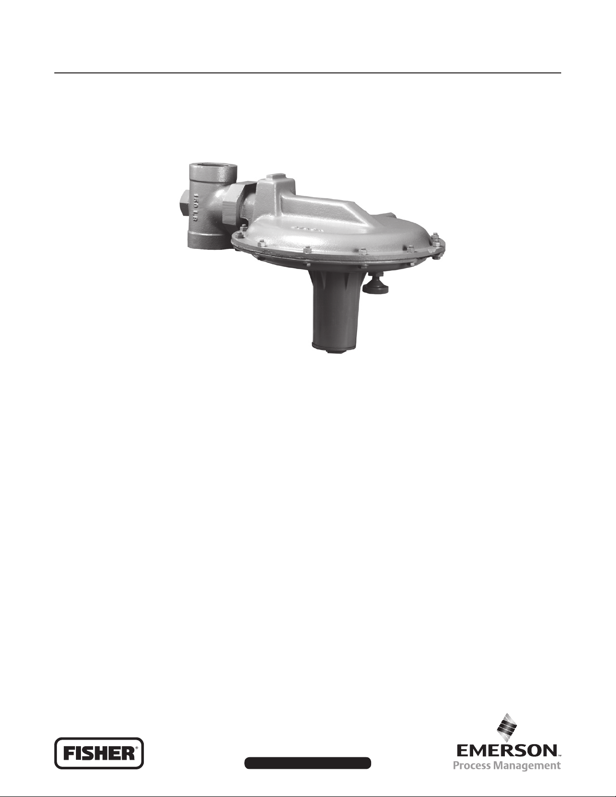
Type Y696 Vapor Recovery Regulator
January 2010
W5996
Figure 1. Type Y696 Vapor Recovery Regulator
Features
• Simplicity—Direct-operated, straight forward stem and
lever design minimizes the number of parts while
providing excellent regulation of pressure.
• Precision Control—Large diaphragm area provides very
accurate throttling control at low set pressures.
• Rugged Construction—Heavy duty castings and
internal parts are designed to lessen vibration and shock.
• Ease of Inspection and Maintenance—The union nut
connection permits maintenance or inspection of critical
parts without removing the body from the line.
• Variety of Construction Materials—Body and lower
casing are available in cast iron, steel, stainless steel,
or Hastelloy® C. Spring case is available in cast iron,
steel, or stainless steel. Trim is available in stainless
steel or Hastelloy® C.
Introduction
The Accu-Pressure™ Type Y696 is a direct-operated vapor
recovery regulator with internal registration, requiring no
downstream control line. This regulator is used to sense
an increase vessel pressure and vent excessive internal
tank pressure to an appropriate vapor recovery disposal
or reclamation system. However, inlet pressures, outlet
pressures, and other performance characteristics vary
according to construction.
Hastelloy® C is a mark owned by Haynes Internatio nal, Inc.
D102054X012
www.sherregulators.com
Page 2
Bulletin 74.2:Y696
Specications
Body Size and End Connection Style
(1)
See Table 1
Maximum Allowable Inlet and Outlet Pressure
15 psig (1,0 bar)
Orice Diameter
1-inch (25 mm)
Control Pressure Ranges
See Table 2
Flow Capacities
See Table 7
Wide-Open Flow Coefcients
CV: 14.7
Cg: 515
C1: 35
Pressure Registration
Internal
Vent Connections
1/4 NPT
Spring Case Connection
1/4 NPT
Common Services and Material Compatibility
See Tables 3 and 4
Temperature Capabilities
Nitrile (NBR): -20° to 180°F (-29° to 82°C)
(2)
Fluorocarbon (FKM): 40° to 300°F (4° to 149°C)
Peruoroelastomer (FFKM): 0° to 300°F (-18ۜ° to 149°C)
(2)
Ethylenepropylene (EPDM): -20° to 275°F (-29° to 135°C)
Approximate Weight
Cast iron: 45 pounds (20 kg)
Steel and Stainless Steel: 57 pounds (26 kg)
Construction Materials
Body and Union Nut: Cast iron, Steel,
CF8M Stainless steel, or Hastelloy® C
Spring Case: Cast iron, Steel, or CF8M Stainless steel
Diaphragm Case Assembly: Cast iron, Steel,
CF8M Stainless steel, or Hastelloy® C
Control Spring, Control Spring Seat, and
Diaphragm Plate: Plated Steel
Diaphragm: Nitrile (NBR) (standard),
Fluorocarbon (FKM), or Ethylenepropylene (EPDM)
Disk Assembly: 303 Stainless steel disk holder
with Nitrile (NBR) or Ethylenepropylene (EDPM) disk;
316 Stainless steel disk holder with Nitrile (NBR),
Fluorocarbon (FKM), Peruoroelastormer (FFKM), or
Polytetrauoroethylene (PTFE) disk; or Hastelloy® C
disk holder with PTFE disk
Orice, Pusher Post, Lever Assembly, Stem,
and Cotter Pin: 303 Stainless steel,
316 Stainless steel, or Hastelloy® C
Gaskets: Composition
1. End connections for other than U.S. standard can usually be provided, consult your local Sales Ofce.
2. The pressure/temperature limits in this Bulletin or any applicable standard limitation should not be exceeded.
Table 1. Body Sizes and End Connection Style
BODY SIZE,
NPS (DN)
1-1/2 and 2 (40 and 50) NPT
Cast Iron Steel Stainless Steel Hastelloy® C
NPT, SWE, CL150 RF,
CL300 RF, PN 16/25/40
BODY MATERIAL
NPT, SWE, CL150 RF,
CL300 RF, PN 16/25/40
Table 2. Control Pressure Ranges
CONTROL PRESSURE RANGE
2 to 5-inches w.c.
5 to 15-inches w.c.
8-inches w.c. to 1 psig
1 to 2.8 psig
2 to 3.5 psig
4 to 7 psig
1. Spring ranges based on spring case installed pointed down. When installed pointed up, spring range increases 2-inches w.c. (5 mbar).
2. Do not use Fluorocarbon (FKM) diaphragm with these springs at diaphragm temperatures lower than 60°F (16°C).
(5 to 12 mbar)
(12 to 37 mbar)
(20 to 69 mbar)
(69 mbar to 0,19 bar)
(0,14 to 0,24 bar)
(0,28 to 0,48 bar)
(1)(2)
(1)(2)
SPRING PART
NUMBER
1A200127022
1B766627062
0B019427052
0A081127202
0Y066427022
1H802427032
SPRING COLOR
Red
Gray
Dark Green
Orange
Green stripe
Red
SPRING WIRE DIAMETER,
INCHES (mm)
0.135 (3,43)
0.156 (3,96)
0.187 (4,75)
0.250 (6,35)
0.363 (9,22)
0.406 (10,3)
CL150 RF
SPRING FREE LENGTH,
INCHES (mm)
5.38 (137)
6.63 (168)
6.00 (152)
6.00 (152)
6.00 (152)
6.00 (152)
2
Page 3
E0751
INLET PRESSURE
OUTLET PRESSURE
ATMOSPHERIC PRESSURE
INLET PRESSURE
OUTLET PRESSURE
ATMOSPHERIC PRESSURE
Bulletin 74.2:Y696
INLET PRESSURE
OUTLET PRESSURE
ATMOSPHERIC PRESSURE
INLET PRESSURE
OUTLET PRESSURE
ATMOSPHERIC PRESSURE
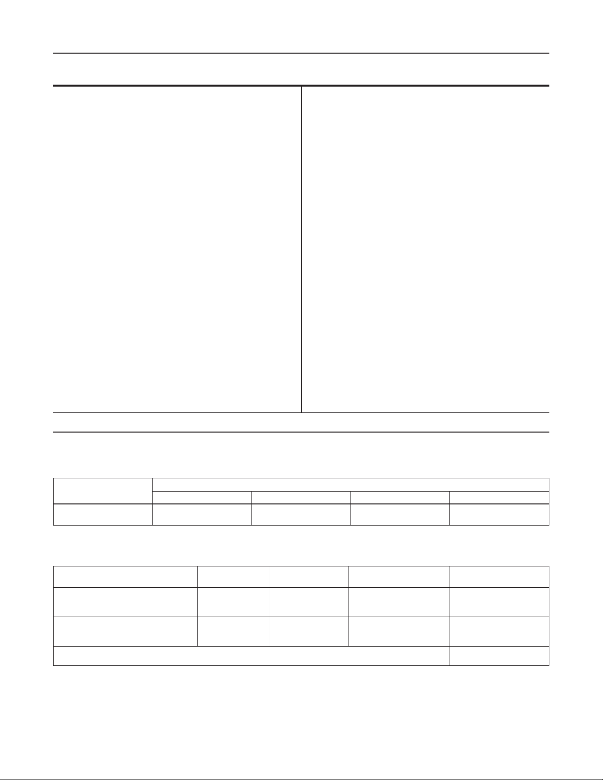
Figure 2. Operational Schematic
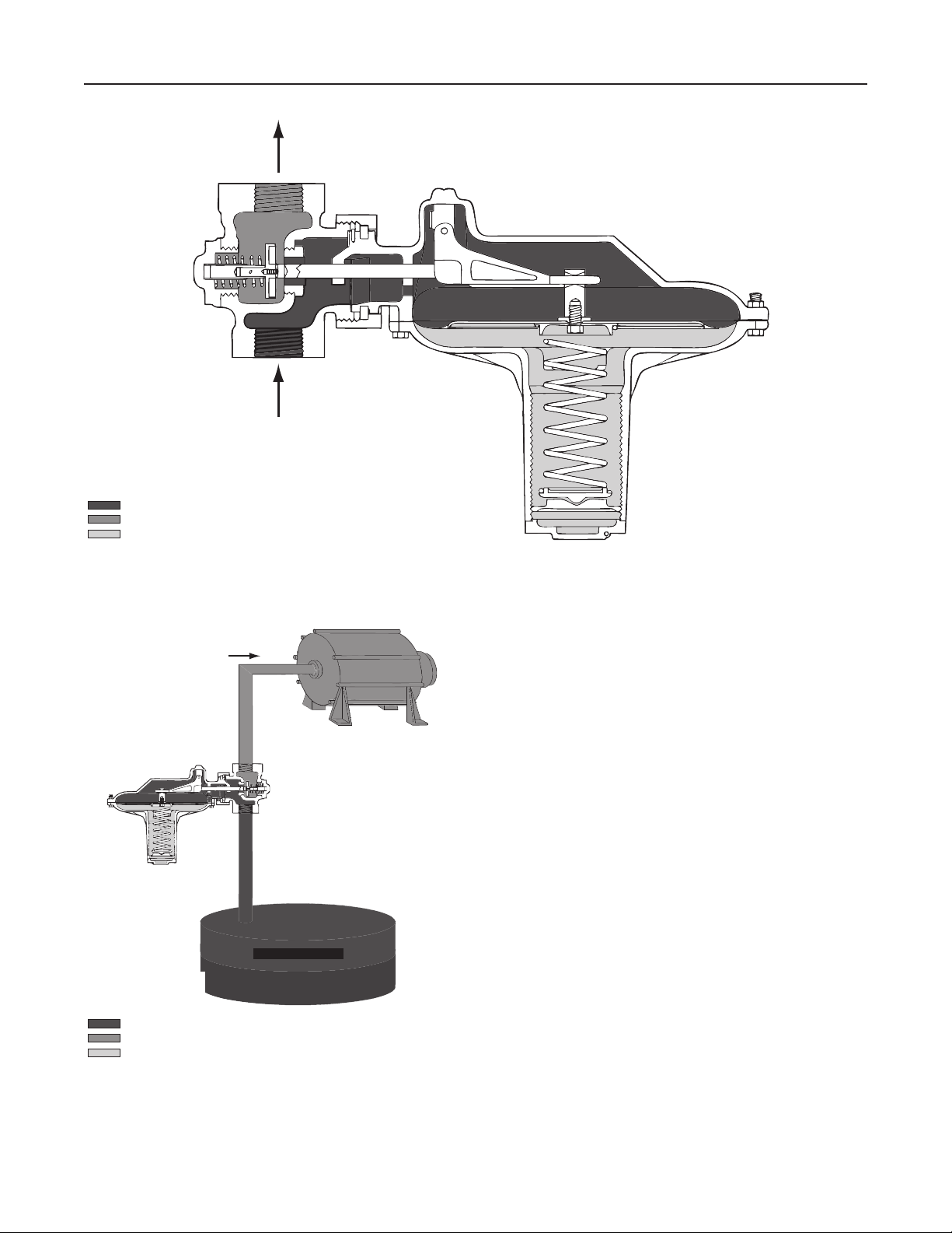
VAPOR RECOVERY
VACUUM SOURCE
VAPOR PRESSURE
LIQUID
INLET PRESSURE
OUTLET PRESSURE
ATMOSPHERIC PRESSURE
Figure 3. Principal of Operational Schematic
Principle of Operation
The Type Y696 vapor recovery regulator is used to maintain
a constant blanket (inlet) pressure or vessel pressure with
the outlet owing to a system whose pressure is lower than
that at the inlet.
When vessel pressure increases above the setpoint of the
regulator due to pumping in or thermal heating, the force
of the control spring is overcome by pressure acting on the
diaphragm. This moves the disk away from the orice allowing
gas to ow from the vessel to the vapor recovery system.
As vessel pressure is reduced, the force of the control
spring causes the disk to move toward the orice
decreasing the ow of gas out of the vessel. As vessel
pressure drops below the setpoint of the regulator, the disk
will seat against the orice shutting off the ow of gas.
Sizing Vapor Recovery Systems
To determine the capacity required, you must consider the
amount of blanketing gas that must be displaced from the
tank when either lling the vessel with liquid (pump-in) or the
expansion of tank vapors during atmospheric thermal heating.
Using the established procedures from American Petroleum
Institute Standard 2000 (API 2000), determine the required
ow rate for outbreathing.
3
Page 4

Bulletin 74.2:Y696
Table 3. Fluid Compatibility of Metals
FLUID
Acetaldehyde
Acetic Acid, Air Free
Acetic Acid, Aerated
Acetic Acid Vapors
Acetone
Acetylene
Alcohols
Aluminum Sulfate
Ammonia
Ammonium Chloride
Ammonium Nitrate
Ammonium Phosphate
Ammonium Sulfate
Ammonium Sulte
Aniline
Asphalt
Beer
Benzene (Benzol)
Benzoic Acid
Boric Acid
Butane
Calcium Chloride (Alkaline)
Calcium Hypochlorite
Carbolic Acid
Carbon Dioxide, Dry
Carbon Dioxide, Wet
Carbon Disulde
Carbon Tetrachloride
Carbonic Acid
Chlorine Gas, Dry
Chlorine Gas, Wet
Chlorine, Liquid
Chromic Acid
Citric Acid
Coke Oven Gas
Copper Sulfate
Cottonseed Oil
Creosote
Ethane
Ether
Ethyl Chloride
Ethylene
Ethylene Glycol
Ferric Chloride
Formaldehyde
Formic Acid
Freon, Wet
Freon, Dry
Furfural
Gasoline, Rened
Glucose
A - Recommended
B - Minor to moderate effect. Proceed with caution.
C - Unsatisfactory
IL - Information lacking
Carbon
Steel
A
C
C
C
A
A
A
C
A
C
A
C
C
C
C
A
B
A
C
C
A
B
C
B
A
C
A
B
C
A
C
C
C
IL
A
C
A
A
A
B
C
A
A
C
B
IL
B
B
A
A
A
Cast
Iron
A
C
C
C
A
A
A
C
A
C
C
C
C
C
C
A
B
A
C
C
A
B
C
B
A
C
A
B
C
A
C
C
C
C
A
C
A
A
A
B
C
A
A
C
B
C
B
B
A
A
A
MATERIAL
316
Stainless
Steel
A
B
A
A
A
A
A
A
A
B
A
A
A
A
A
A
A
A
A
A
A
B
B
A
A
A
A
B
B
B
C
C
B
A
A
B
A
A
A
A
A
A
A
C
A
B
A
A
A
A
A
Hastelloy® C
A
A
A
A
A
A
A
A
A
A
A
A
A
A
A
A
A
A
A
A
A
A
A
A
A
A
A
A
A
A
B
A
A
A
A
A
A
A
A
A
A
A
IL
B
A
A
A
A
A
A
A
FLUID
Hydrochloric Acid, Aerated
Hydrochloric Acid, Air free
Hydrouoric Acid, Aerated
Hydrouoric Acid, Air free
Hydrogen
Hydrogen Peroxide
Hydrogen Sulde, Liquid
Magnesium Hydroxide
Mercury
Methanol
Methyl Ethyl Ketone
Milk
Natural Gas
Nitric Acid
Oleic Acid
Oxalic Acid
Oxygen
Petroleum Oils, Rened
Phosphoric Acid, Aerated
Phosphoric Acid, Air Free
Phosphoric Acid Vapors
Picric Acid
Potassium Chloride
Potassium Hydroxide
Propane
Rosin
Silver Nitrate
Sodium Acetate
Sodium Carbonate
Sodium Chloride
Sodium Chromate
Sodium Hydroxide
Sodium Hypochloride
Sodium Thiosulfate
Stannous Chloride
Stearic Acid
Sulfate Liquor (Black)
Sulfur
Sulfur Dioxide, Dry
Sulfur Trioxide, Dry
Sulfuric Acid (Aerated)
Sulfuric Acid (Air Free)
Sulfurous Acid
Trichloroethylene
Turpentine
Vinegar
Water, Boiler Feed
Water, Distilled
Water, Sea
Zinc Chloride
Zinc Sulfateilled
Carbon
Steel
C
C
B
A
A
IL
C
A
A
A
A
C
A
C
C
C
A
A
C
C
C
C
B
B
A
B
C
A
A
C
A
A
C
C
B
A
A
A
A
A
C
C
C
B
B
C
B
A
B
C
C
Cast
Iron
C
C
C
C
A
A
C
A
A
A
A
C
A
C
C
C
A
A
C
C
C
C
B
B
A
B
C
A
A
C
A
A
C
C
B
C
A
A
A
A
C
C
C
B
B
C
C
A
B
C
C
MATERIAL
316
Stainless
Steel
C
C
B
B
A
A
A
A
A
A
A
A
A
B
A
B
A
A
A
A
B
A
A
A
A
A
A
A
A
B
A
A
C
A
A
A
A
A
A
A
C
C
B
A
A
A
A
A
B
C
A
Hastelloy® C
B
B
A
A
A
B
A
A
A
A
A
A
A
B
A
A
A
A
A
A
IL
A
A
A
A
A
A
A
A
A
A
A
A
A
A
A
A
A
A
A
A
A
A
A
A
A
A
A
A
A
A
1. Determine the ow rate of blanketing gas displaced when
liquid is being pumped in (see Table 6).
2. Determine the gas ow rate due to “outbreathing”
caused by atmospheric thermal heating (see Table 5).
3. Add the requirements of 1 and 2 and select a vapor
recovery regulator size based on total capacity required
from Table 7.
4
Sample sizing problem:
Vessel Capacity . . . . . . . . . 168 000 gallons (636 000 liters)
Pump In Capacity . . . . . . . . . . . . . . . . . 50 GPM (189 l/min)
Desired Vapor Recovery . . . . . . . . . 2-inches w.c. (5 mbar)
Vapor Recovery Vacuum Source . . . . . . . . . . . . 5-inches Hg
1. From Table 6 the desired air ow rate due to pump in
equals 50 GPM (189 l/min) x 8.01 = 400 SCFH
(10,7 Nm3/h) air.
Page 5

Table 4. Fluid Compatibility of Elastomers
FLUID
Acetic Acid (30%)
Acetone
Air, Ambient
Air, Hot [200°F (93°C)]
Alcohol (Ethyl)
Alcohol (Methyl)
Ammonia (Anhydrous)(Cold)
Ammonia (Gas, Hot)
Beer
Benzene
Brine (Calcium Chloride)
Butadiene Gas
Butane (Gas)
Butane (Liquid)
Carbon Tetrachloride
Chlorine (Dry)
Chlorine (Wet)
Coke Oven Gas
Ethyl Acetate
Ethylene Glycol
Freon 11
Freon 12
Freon 22
Freon 114
Gasoline (Automotive)
Hydrogen Gas
Hydrogen Sulde (Dry)
Hydrogen Sulde (Wet)
Jet Fuel (JP-4)
Methyl Ethyl Ketone (MEK)
MTBE
Natural Gas
Nitric Acid (50 to 100%)
Nitrogen
Oil (Fuel)
Propane
Sulfur Dioxide
Sulfuric Acid (up to 50%)
Sulfuric Acid (50 to 100%)
Water (Ambient)
Water [at 200°F (93°C)]
1. Performance worsens with hot temperatures.
A - Recommended
B - Minor to moderate effect. Proceed with caution.
C - Unsatisfactory
N/A - Information not available
Neoprene (CR) Nitrile (NBR) Fluorocarbon (FKM) Ethylenepropylene (EPDM) Peruoroelastomer (FFKM)
B
C
A
C
A
A
A
B
A
C
A
C
A
C
C
C
C
C
C
A
C
A
A
A
C
A
A
B
B
C
C
A
C
A
C
B
A
B
C
A
C
Bulletin 74.2:Y696
MATERIAL
C
C
A
B
C
A
A
C
A
C
A
C
A
A
C
C
C
C
C
A
B
A
C
A
B
A
(1)
A
C
A
C
C
A
C
A
A
A
C
C
C
A
B
C
C
A
A
C
C
C
C
A
B
B
B
A
A
A
A
B
A
C
A
A
B
C
B
A
A
C
C
A
C
C
A
B
A
A
A
A
A
A
A
B
A
A
A
A
A
A
A
B
A
C
A
C
C
C
C
C
C
C
B
A
C
B
A
A
C
A
A
A
C
A
C
C
C
A
C
C
A
B
B
A
A
A
A
A
A
A
A
A
A
A
A
A
A
A
A
A
A
A
A
A
A
A
A
A
A
A
A
A
A
A
A
A
A
A
A
A
A
A
A
A
A
A
2. From Table 5 the desired air ow rate = 4000 SCFH
(107 Nm3/h) air due to thermal heating.
3. Total required ow rate = 4400 SCFH (118 Nm3/h) air.
4400 SCFH (118 Nm3/h) converts to 4500 SCFH
(121 Nm3/h) nitrogen.
4. From Table 7, with a 2-inches w.c. (5 mbar), and an outlet
pressure of 5-inches Hg, an NPS 1-1/2 or 2 (DN 40 or 50)
body size would ow 5130 SCFH (137 Nm3/h) nitrogen.
This would satisfy the desired ow rate of 4500 SCFH
(121 Nm3/h) nitrogen.
Capacity Information
Table 7 gives typical nitrogen regulating capacities at
selected inlet pressures and outlet pressure settings. Flows
are in SCFH (at 60°F and 14.7 psia) and Nm3/h (at 0°C and
1,01325 bar) of 0.97 specic gravity nitrogen. For gases of
other specic gravities, multiply the given SCFH capacity
of nitrogen by 0.985, and divide by the square root of the
appropriate specic gravity of the gas required. Then, if
capacity is desired in Nm3/h, multiply SCFH by 0.0268.
5
Page 6

Bulletin 74.2:Y696
Table 5. Gas Flow Required for Thermal Heating (Outbreathing) per API 2000 (Interpolate for Intermediate Sizes)
TANK CAPACITY,
BARRELS
60
100
500
1000
2000
3000
4000
5000
10 000
15 000
20 000
25 000
30 000
35 000
40 000
45 000
50 000
60 000
70 000
80 000
90 000
100 000
120 000
140 000
160 000
180 000
TANK CAPACITY,
GALLONS
2500
4200
21 000
42 000
84 000
126 000
168 000
210 000
420 000
630 000
840 000
1 050 000
1 260 000
1 470 000
1 680 000
1 890 000
2 100 000
2 520 000
2 940 000
3 360 000
3 780 000
4 200 000
5 040 000
5 880 000
6 720 000
7 560 000
OUTBREATHING (FLASH POINT
< 100°F OR NORMAL BOILING POINT
< 300°F), SCFH AIR
60
100
500
1000
2000
3000
4000
5000
10 000
15 000
20 000
24 000
28 000
31 000
34 000
37 000
40 000
44 000
48 000
52 000
56 000
60 000
68 000
75 000
82 000
90 000
TANK CAPACITY,
3
m
10
20
100
200
300
500
700
1000
1500
2000
3000
3180
4000
5000
6000
7000
8000
9000
10 000
12 000
14 000
16 000
18 000
20 000
25 000
30 000
OUTBREATHING (FLASH POINT
< 38°C OR NORMAL BOILING POINT
< 149°C), Nm3/h AIR
1,6
2,7
13,4
26,8
53,6
80,4
107
134
268
402
536
643
750
831
911
992
1072
1179
1286
1394
1501
1608
1822
2010
2198
2412
Table 6. Flow Rate Conversion
MULTIPLY MAXIMUM PUMP RATE OUT: BY TO OBTAIN
U.S. GPM
U.S. GPH
m3/hr
Barrels/hour
Barrels/day
1. Gas ow of blanketing gas to replace liquid pumped out.
(1)
8.021
0.1337
1.01
5.615
0.2340
Table 7. Capacities
OUTLET PRESSURE RANGE,
SPRING PART NUMBER,
AND COLOR
2 to 5-inches w.c.
(5 to 12 mbar)
1A200127022, Red
5 to 15-inches w.c.
(12 to 37 mbar)
1B766627062, Gray
8-inches w.c. to 1 psig
(20 to 69 mbar)
0B019427052, Dark Green
1 to 2.8 psig
(69 mbar to 0,19 bar)
0A081127202, Orange
2 to 3.5 psig
(0,14 to 0,24 bar)
0Y066427022, Green Stripe
4 to 7 psig
(0,28 to 0,48 bar)
1H802427032, Red
SET PRESSURE
2-inches w.c.
(5 mbar)
4-inches w.c.
(10 mbar)
15-inches w.c.
(37 mbar)
21-inches w.c.
(52 mbar)
2 psig
(0,14 bar)
3 psig
(0,21 bar)
5 psig
(0,34 bar)
BUILDUP TO OBTAIN
WIDE-OPEN TRAVEL
2.6-inches w.c.
(6 mbar)
2.6-inches w.c.
(6 mbar)
3.9-inches w.c.
(10 mbar)
7.7-inches w.c.
(19 mbar)
23-inches w.c.
(57 mbar)
3.2 psig
(0,22 bar)
5.87 psig
(0,41 bar)
OUTLET PRESSURE
VACUUM
0 psig (0 bar)
2.5 psig (0,17 bar)
5 psig (0,34 bar)
0 psig (0 bar)
2.5 psig (0,17 bar)
5 psig (0,34 bar)
0 psig (0 bar)
2.5 psig (0,17 bar)
5 psig (0,34 bar)
0 psig (0 bar)
2.5 psig (0,17 bar)
5 psig (0,34 bar)
0 psig (0 bar)
2.5 psig (0,17 bar)
5 psig (0,34 bar)
0 psig (0 bar)
2.5 psig (0,17 bar)
5 psig (0,34 bar)
0 psig (0 bar)
2.5 psig (0,17 bar)
5 psig (0,34 bar)
(1)
:
SCFH
SCFH
Nm3/h
SCFH
SCFH
CAPACITIES IN SCFH (Nm3/h)
OF 0.97 SPECIFIC GRAVITY
NITROGEN
1420 (38,1)
5130 (137)
6560 (176)
1680 (45,0)
5200 (139)
6600 (177)
2810 (75,3)
5580 (150)
6850 (184)
3510 (94,1)
5950 (159)
7160 (192)
5820 (156)
7410 (199)
8340 (224)
8790 (236)
10 400 (279)
9770 (262)
12 000 (322)
12 700 (340)
13 100 (351)
6
Page 7

17.44
(443)
10.38
(264)
2.25
(57)
Bulletin 74.2:Y696
7.06
(179)
GAUGE TAP
1/4 NPT
TYPE Y602
VENT
CAST IRON
1/4 NPT VENT
CONNECTION
Figure 4. Dimensions
STEEL OR STAINLESS STEEL
3/4 NPT VENT
To determine regulating capacities at pressure settings not
given or to determine wide-open ow capacities, use the
following formula:
520
Q = CgP1SIN
GT
3417
)
C
∆P
DEG
)
P
1
1
where:
Q = gas ow rate, SCFH
C
P
G = specic gravity of the gas
= gas sizing coefcient
g
= absolute inlet pressure, psia
1
T = absolute temperature of gas at inlet, °Rankine
C
∆P = pressure drop across the regulator, psi
= ow coefcient
1
7.00
14.00
(356)
(178)
8.94
(227)
5.19
(132)
2.94
(75)
5.88
(149)
Ordering Guide
Body Size (Select One)
NPS 1-1/2 (DN 40)
NPS 2 (DN 50)
Body Material and End Connection Style (Select One)
Cast Iron Hastelloy® C
NPT*** NPT*
CL150 RF*
CL300 RF*
WCC Steel CF8M Stainless Steel
NPT*** NPT**
CL150 RF** CL150 RF**
CL300 RF** CL300 RF**
PN 16/25/40* PN 16/25/40*
11.88
(302)
INCHES
(mm)
Installation
Install the regulator using a straight run of pipe the same
size as or larger than the regulator body. Flow through the
regulator body is indicated by the ow arrow cast, stamped
or riveted on the body. If a block valve is required, install
a full ow valve between the regulator and the blanketed
vessel. For proper operation at low setpoint ranges, the
Type Y696 regulators should be installed with the spring
case barrel pointed down.
Ordering Information
Carefully review each specication and complete the
Ordering Guide. To ensure ordering accuracy, please
complete the Specications Worksheet on the last page.
Spring Case Material (Select One)
Cast iron***
WCC Steel***
CF8M Stainless steel**
Diaphragm Case Material (Select One)
Cast iron***
WCC Steel***
CF8M Stainless steel**
Hastelloy® C*
Trim Material (Select One)
303 Stainless steel***
316 Stainless steel (not available with
Ethylenepropylene (EPDM))**
Hastelloy® C (only available with PTFE)*
- continued -
7
Page 8

Bulletin 74.2:Y696
Ordering Guide (continued)
Diaphragm Material (Select One)
Nitrile (NBR) (standard)***
Fluorocarbon (FKM)**
Nitrile (NBR) with PTFE Protector**
Disk Material (Select One)
Nitrile (NBR) (standard)***
Fluorocarbon (FKM)***
Peruoroelastomer (FFKM)*
Ethylenepropylene (EPDM)*
PTFE*
Outlet Pressure Range (Select One)
2 to 5-inches w.c. (5 to 12 mbar) Red***
5 to 15-inches w.c. (12 to 37 mbar) Gray***
8-inches w.c. to 1 psig (20 to 69 mbar) Dark Green***
1 to 2.8 psig (69 mbar to 0,19 bar) Orange***
2 to 3.5 psig (0,14 to 0,24 bar) Green Stripe***
4 to 7 psig (0,28 to 0,48 bar) Red***
Regulators Quick Order Guide
* * * Standard - Readily Available for Shipment
* * Non-Standard - Allow Additional Time for Shipment
Special Order, Constructed from Non-Stocked Parts.
*
Consult your local Sales Ofce for Availability.
Availability of the product being ordered is determined by the component with the
longest shipping time for the requested construction.
Replacement Parts Kit (Optional)
Yes, send one parts kit to match this order.
Vapor Recovery Specication Worksheet
Application Specications:
Tank Size
Pump In Rate
Pump Out Rate
Blanketing Gas (Type and Specic Gravity)
Pressure Requirements:
Control Pressure Setting
Downstream Pressure
Maximum Flow (Q
max
)
Build-up Limitations:
0.25-inches w.c. (0,6 mbar)
1-inch w.c. (2 mbar)
0.5-inches w.c. (1 mbar)
2-inches w.c. (5 mbar)
Others
Other Specications:
Is a tank blanketing regulator required?
Special Material Requirements:
Ductile Iron
Stainless Steel Hastelloy® C
Yes No
Other
Other Requirements:
Steel
Industrial Regulators
Emerson Process Management
Regulator Technologies, Inc.
USA - Headquarters
McKinney, Texas 75069-1872 USA
Tel: 1-800-558-5853
Outside U.S. 1-972-548-3574
Asia-Pacic
Shanghai, China 201206
Tel: +86 21 2892 9000
Europe
Bologna, Italy 40013
Tel: +39 051 4190611
Middle East and Africa
Dubai, United Arab Emirates
Tel: +971 4811 8100
For further information visit www.sherregulators.com
The Emerson logo is a trademark and service mark of Emerson Electric Co. All other marks are the property of their prospective owners. Fisher is a mark owned by Fisher Controls, Inc., a
business of Emerson Process Management.
The contents of this publication are presented for informational purposes only, and while every effort has been made to ensure their accuracy, they are not to be construed as warranties or
guarantees, express or implied, regarding the products or services described herein or their use or applicability. We reserve the right to modify or improve the designs or specications of such
products at any time without notice.
Emerson Process Management does not assume responsibility for the selection, use or maintenance of any product. Responsibility for proper selection, use and maintenance of any Emerson
Process Management product remains solely with the purchaser.
Natural Gas Technologies
Emerson Process Management
Regulator Technologies, Inc.
USA - Headquarters
McKinney, Texas 75069-1872 USA
Tel: 1-800-558-5853
Outside U.S. 1-972-548-3574
Asia-Pacic
Singapore, Singapore 128461
Tel: +65 6777 8211
Europe
Bologna, Italy 40013
Tel: +39 051 4190611
Gallardon, France 28320
Tel: +33 (0)2 37 33 47 00
TESCOM
Emerson Process Management
Tescom Corporation
USA - Headquarters
Elk River, Minnesota 55330-2445 USA
Tel: 1-763-241-3238
Europe
Selmsdorf, Germany 23923
Tel: +49 (0) 38823 31 0
©Emerson Process Management Regulator Technologies, Inc., 2001, 2010; All Rights Reserved
 Loading...