

Emerson XL281, XL131, XL221, XL426, XL681 Installation, Operation & Maintenance Instructions Manual
...
Installation Operation & Maintenance Instructions
Hytork XL
MAC050515 EN Rev. C
May 2016
www.Hytork.com
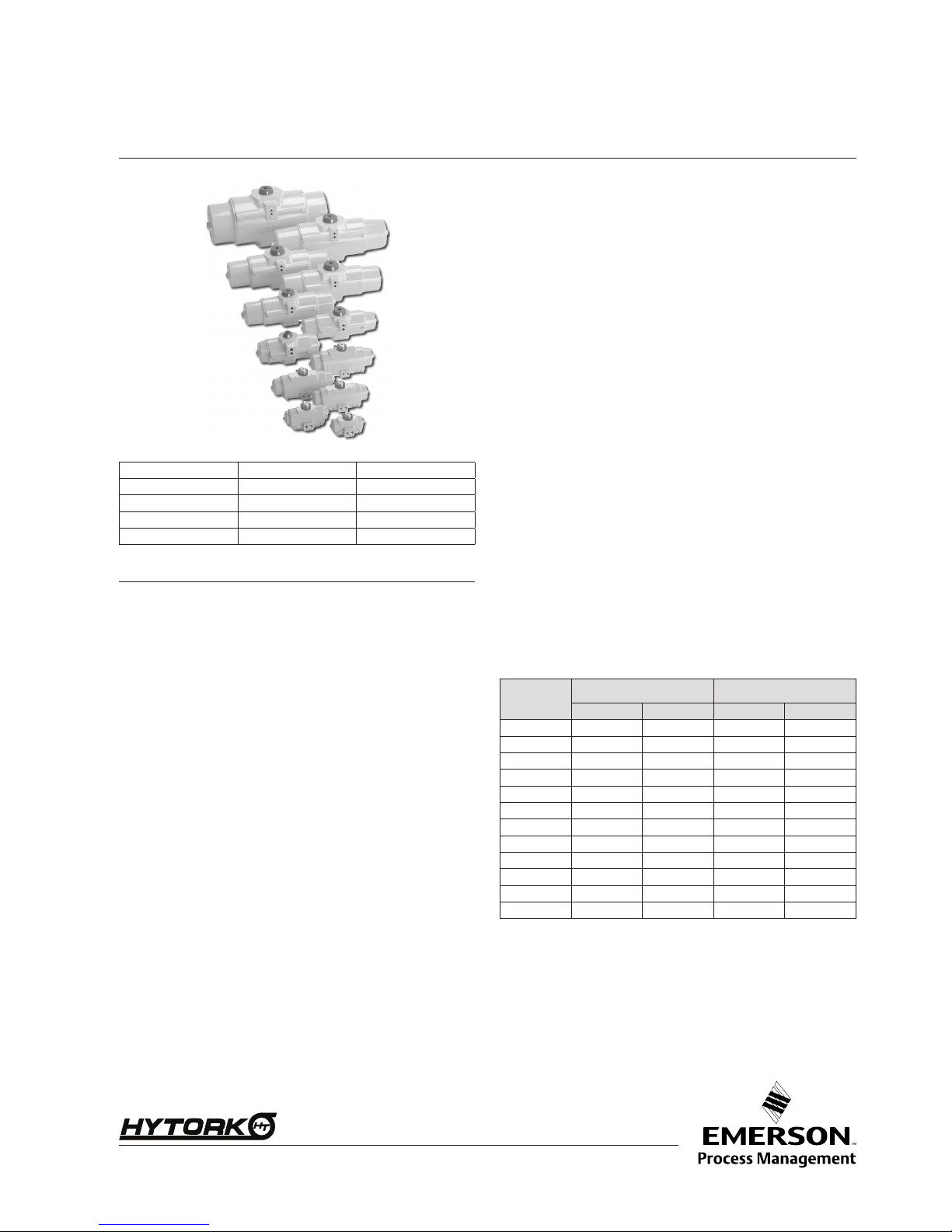
Table 1 Applicable Models:
XL 26 XL 281 XL 2586
XL 71 XL 426 XL 4581
XL 131 XL 681
XL 186
XL 1127
XL 221 XL 1372
1 Important Safety Procedures
Installation, adjustment, putting into service, use, assembly, disas-
sembly and maintenance of the Actuator is strictly reserved to quali-
ed personnel.
Before installation, operation and maintenance, read the relevant
sections of:
- This manual
- Quick Reference Guide: DOC.QRG.XL
Caution: Always disconnect the Air and Electrical supplies before
carrying out any form of maintenance on an Actuator.
Caution: When removing any ball valve or plug valve assemblies
from a pipe system, isolate the piping system on which the Actuator
is installed and relieve any media pressure that may be trapped in
the valve cavities before removing the Actuator for maintenance.
Caution: Always contain the Spring tension with HYTORK Retrac-
tor Rods as explained in Section 9 (Disassembly procedure). Follow
instructions for using the Retractor Rod carefully. Only HYTORK
manufactured or approved Retractor Rods are to be used for Spring
removal. As with any threaded tool that is frequently used Retractor
Rods should be checked to ensure that the threads are not worn or
damaged in any way and greased regularly. Any damaged or worn
Rods must not be used and must be destroyed.
Never attempt to ‘BLOW OUT’ the Pistons or the End caps from the
Actuator Body by using air pressure.
Never turn the stop screws completely out when the actuator is
under pressure
Numbers in brackets (#) refer to parts on the exploded view drawing
(Fig. 5).
All HYTORK XL Spares Kits are supplied with SAFEKEY assemblies
(13/14) cut to an exact length which will t the circumference of the
End Cap (21) when fully assembled into the Actuator. Any shortened
SAFEKEY must not be used. If in doubt contact Emerson Process
Management or your local HYTORK Stocking Distributor.
Read the relevant sections carefully before continuing.
1.1 Warehouse storage
HYTORK Actuators should be stored in a clean, dry warehouse, free
from excessive vibration and rapid temperature changes.
Actuators should not be stored on any oor surface.
1.2 On site storage
HYTORK actuators should be stored in a clean, dry warehouse, free
from excessive vibration and rapid temperature changes.
Prevent moisture or dirt entering the actuator. Plug or seal both air
connection ports.
Important! Failure to follow proper storage guidelines will void war-
ranty
1.3 Lifting instructions
• Use lifting equipement as required by national or local legislation.
• Use lifting straps to lift the assembly of actuator and valve.
• Do not attach lifting straps to only the actuator, to lift the assem-
bly of actuator and valve.
Table 2 Weight of Actuators
Model
Double Acting
Spring Return with S80
Springs
Kg Lbs Kg Lbs
XL26 1.39 3.06 1.53 3.37
XL71 2.39 5.27 2.78 6.13
XL131 3.90 8.60 4.76 10.49
XL186 4.77 10.52 5.45 12.02
XL221 6.19 13.65 7.76 17.11
XL281 7.02 15.47 9.90 21.83
XL426 7.30 16.10 12.50 27.56
XL681 8.80 19.40 22.50 49.60
XL1127 22.00 48.50 36.00 79.37
XL1372 27.00 59.52 46.60 102.73
XL2586 46.00 101.41 79.00 174.16
XL4581 83.00 182.98 142.00 313.05
Page 2
Hytork XL
Installation Operation & Maintenance Instructions
MAC050515 EN Rev. C
May 2016
2 ATEX instructions for use in (potential)
explosive areas
2.1 Intended use
The Hytork XL series pneumatic actuators are a Group II category
2 equipment and intended for use in areas in which explosive
atmospheres caused by mixtures of air and gases, vapours, mists or
by air/dusts are likely to occur. Therefore it may be used in (ATEX)
classied Zones 1, 2 (Gasses) and/or 21, 22 (Dust).
2.2 Safety instructions
a Assembly, disassembly and maintenance, is only allowed at the
actuator, when, at the time of the activity, there is not an explosive mixture.
b Prevent entry of explosive mixtures into the actuator. We suggest
utilizing a solenoid with a “breather” function on spring return
actuators when used in potentially explosive atmospheres.
c The plastic position indicator caps are approved for ATEX gas
group IIB areas. In areas where ATEX gas group IIC requirements apply, do not use the plastic position indicator cap of sizes
XL426 up to XL4581, to avoid build up of static electricity.
d In order to avoid increasing dust explosion risk, periodically clean
dust deposits from all equipment.
e When equipment is installed in a hazardous area location (po-
tentially explosive atmosphere), prevent sparks by proper tool
selection and avoiding other types of impact energy.
f Proper care must be taken to avoid generation of static electricity
on the non-conductive external surfaces of the equipment (e.g.
rubbing of surfaces, etc.).
g HYTORK XL actuators do not have an inherent ignition source
due to electro-static discharge, but explosion hazard may be
present due to the discharge of static electricity from other valve
assembly components.
– To avoid personal injury or property damage, make sure that
the valve is grounded to the pipeline before placing the valve
assembly into service.
– Use and maintain alternate shaft-to-valve body bonding, such
as a shaft-to-body bonding strap assembly.
2.3 Maximum temperatures
Temperature
Valid for actuator
model
Ambient range ATEX class
TX (ATEX surface
temperature)
-20..75°C T6 T85°C (185°F)
Standard Tem-
perature models
-20..80°C T5 T90°C (194°F)
-20..80°C T1...T4 T90°C (194°F)
-20..75°C T6 T85°C (185°F)
High Temperature
models
-20..90°C T5 T100°C (212°F)
-20..120°C T1...T4 T130°C (266°F)
-40..75°C T6 T85°C (185°F)
Low Temperature
models
-40..80°C T5 T90°C (194°F)
-40..80°C T1...T4 T90°C (194°F)
-20..250°C for
2 hours
T2 T260°C 500°F)
Tunnel
application models
Note:
a The actual maximum surface temperature depends not on the
equipment itself, but mainly on operating conditions like e.g. the
temperature of the supply media.
b The specied values are valid with the following conditions:
- Maximum working frequency of the actuator is 1Hz at a maximum of 50 cycles per hour and at maximum load.
3 Operating Media, Pressures and Temperatures
3.1 Operating media
a Use clean, dry or lubricated air or inert gas.
b Maximum pressure : 8 barg / 116PSI
Note:
On applications where the spring stroke of single acting actuators
is pneumatically operated, the maximum pressure is 6.5 bar /
95PSI
c Dew point 10 K below operating temperature.
d For subzero applications take appro priate measures.
3.2 Operating Temperature range
a Using standard seals and greases the operating temperature
range is -20°C to + 100°C (-4°F to +212°F) as is indicated on the
product label.
b Other medias and temperatures may be used but consult your
local Hytork supplier for conrmation as to suitability.
4 Actuator to Valve Installation
The Pinion drive, coupling device and Valve Stem should be cen-
tered and concentric to prevent any side loading to the Pinion Radial
Bearing and Valve Stem Seat area. Ensure that the coupling shaft to
be operated is a tight but free sliding t into the female drive in the
Actuator Pinion (19).
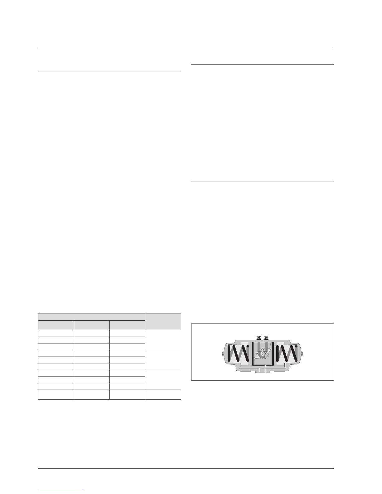
4.1 Bi-directional Travel Stops
Hytork XL actuators have two travel stops (22, 23 and 24) for setting
acurately the travel and the open and closed positions. XL2586 and
XL4581 can be tted with the optional Bottom Stop Block for setting
the travel.
The actuator has a factory set stroke of 90°. The adjustable stroke
range of the actuator is :
- at closed (0°) position : -3° to +7°
- at open (90°) position : -83° to +93°
REMARK:
- If the actuator is assembled for reverse operation, instead of
standard operation, Stop “1” will adjust the “open” position
and stop “2” the “closed” position.
“2” “1”
Stop marked Stop marked
View from above
Fig. 1 Travel stops
Installation Operation & Maintenance Instructions
Hytork XL
Page 3
MAC050515 EN Rev. C
May 2016
4.2 Travel Stop Adjustments
1 Operate valve/actuator assembly to the open position.
2 Remove air supply.
3 Slacken locknut (24) on the “closed” stop (marked “2”).
4 Turn the “closed” stop clockwise to reduce or counter clockwise
to increase the travel.
5 Tighten the lock nut.
6 Connect air and check that the position is correct. If not repeat
from 2.
7 Operate valve/actuator assembly to the “closed” position.
8 Remove air supply.
9 Adjust “open” travel stop (marked “1”) as from step 3 to 6.
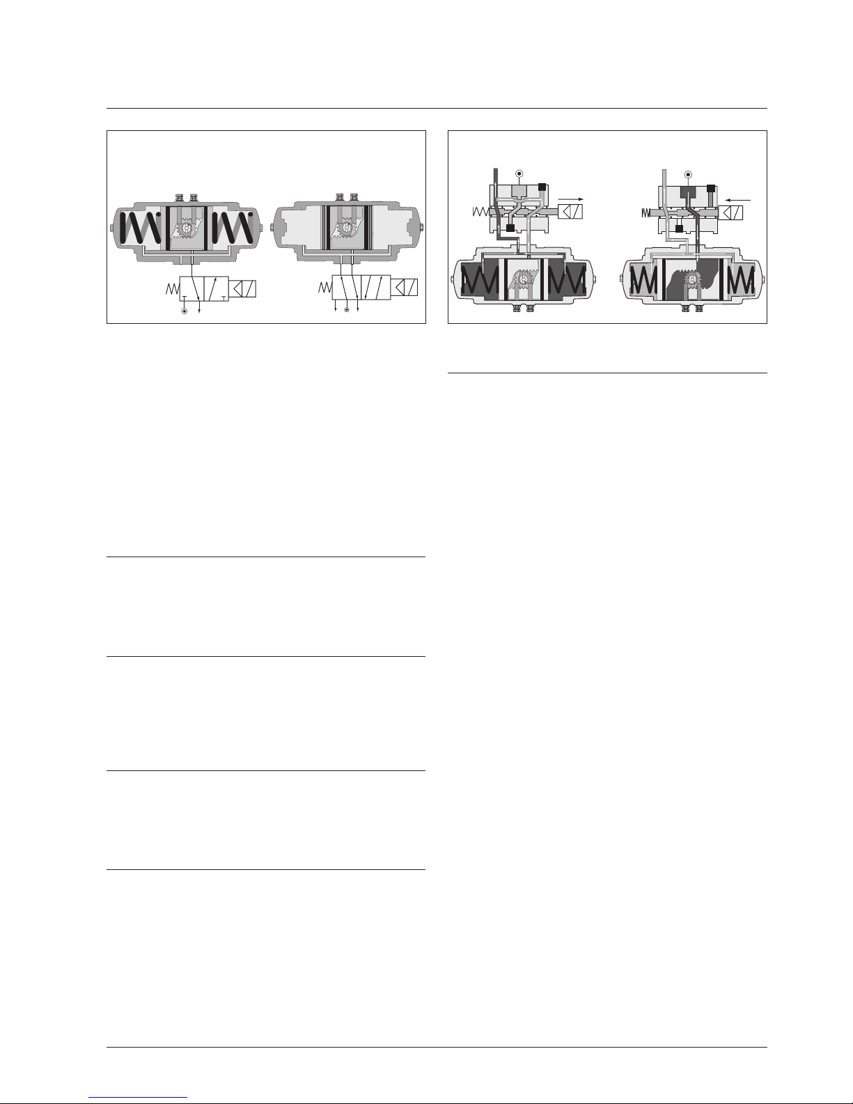
5 Piping Instructions
(See Fig. 2) All Actuators can be either piped with solid or exible
tubing with the solenoid valve mounted remotely from the actuator or
by mounting a NAMUR designed solenoid valve DIRECTLY onto the
NAMUR mounting pad on the side of the actuator.
6 Solenoid Valves on Spring Return Actuators
(See Fig. 3) It is recommended that on Spring Return Actuators,
the HYTORK “CATS” Solenoid Valves are used. These Valves are
specially designed to prevent contamination of the internals of the
Actuator by dirt from the atmosphere. This increases the working life
of the Actuator which reduces down time and maintenance periods.
7 Position feedback
All position feedback or positioning accesories, that comply to the
VDI/VDE 3845 (NAMUR) standard, can be mounted easily on top of
Hytork XL actuators. To access the pinion top, remove the position
indicator.
8 Spares Recommendations
When disassembling and carrying out maintenance work on the
XL Actuator, a HYTORK Spares Kit must be used to replace all ‘O’
Rings, DURASTRIP Bearings, Washers etc. This Kit is available
from Emerson Process Management or its Stocking Distributors.
9 Disassembly procedure
9.1 End cap and springs dis-assembly on Spring
Return actuators
1 Release Locking Nuts (24) and remove both Travel Stops (22)
and Thread Seals (23) or ‘O’-rings (23a).
2 Remove the Indicator (7) from the top of the Pinion (19) For XL26
to XL221 use an Allen key size 4mm. For the larger sizes the
Indicator can by pulled from the pinion top.
3 Remove both Sealing Bolts (28) and seals (29) from the End
Caps (21).
4 Place both the HYTORK Retractor Rods through the hole in the
End Caps and screw the Rods into :
- For XL 26 to XL 681 the Pistons (20)
- For XL 1127 to XL4581 the Retractor plate (20a, see also Fig
5) until travel is stopped (DO NOT OVERTIGHTEN) and take
care the nut and washer being free of the End Cap face.
5 Turn back the Rod 1/2 turn.
6 Screw the adjusting nut and washer by hand clockwise down
the Retractor Rod until they come up against the face of the End
Cap.
7 Prevent the “hold-nuts “ to rotate by one wrench. Use another
wrench, to screw both adjusting nuts half turn at a time (see Fig.
5) clockwise down the Rods until the end cap loosens (Maximum;
approximately two complete turns). This draws the;
- For XL 26 to XL681 the Pistons (20)
- For XL 1127 to XL4581 the Retractor plate (see also Fig 5) to
the end caps (21) and compresses the springs. This Spring-
compression, releases the Spring force and un-locks the
SAFEKEY for removal.
8 Rotate the Caps to ensure that the Springs are retracted; if the
Cap will not turn easily, a gentle tapping with a plastic hammer
against the endcap will loosen the end cap.
9 Unscrew the two slotted SAFEKEYS (13/14), and gently pull
each SAFEKEY from the Body. If the SAFEKEY resists removal,
gently tap the End Cap with a soft hammer to assist release.
10 When both SAFEKEYS have been removed, use a wrench to
rotate the Pinion, driving the pistons (20) apart until they partially
push the End Caps from the Body.
- For XL 26 to XL681 the Pistons (20), springs and end cap will
come out
- For XL 1127 to XL4581 the Retractor plate, springs and end
cap will come out.
Spring return actuator
operation
Double acting actuator
operation
Spring stroke operation Air stroke operation
Fig. 2 Solenoid operation
Fig. 3 HYTORK “CATS” Solenoid Valve
 Loading...