

Emerson XJAM-030Z-TFC-022, XJAL-050Z-TFC-012, XJAL-050Z-CFV-022, XJAM-030Z-TFC-012, XJAL-020Z-CFV-022 User Manual
...Page 1

© 2017 Emerson Climate Technologies, Inc.
1
TABLE OF CONTENTS
Safety Instructions ..................................................... 2
Safety Icon Explanation
.......................................... 2
Instructions Pertaining to Risk of Electrical Shock,
Fire, or Injury to Persons .......................................... 3
Safety Statements
................................................... 3
1. Introduction ......................................................... 4
2. Nomenclature/Features ...................................... 4
3. Understanding Actual vs. Standard Airflow .... 4
4. Performance Data ............................................... 4
5. Electrical / Physical Data ................................... 4
6. Generator Requirements ................................... 4
7. Physical Dimensions .......................................... 5
8. Installation / Piping Instructions ....................... 5
9. Condensing Unit Operational Control .............. 5
10. Control Features ............................................ 5
10.1. Fresh Start Program .................................... 5
10.2. Stop Program ............................................... 5
10.3. Automatic Liquid Injection (Medium
temperature units only) ............................................. 5
10.4. Compressor Phase Reversal ....................... 5
10.5. Loss of Phase Protection ............................. 6
10.6. Motor Current Overload ................................ 6
10.7. Non-Adjustable High Pressure Control ........ 6
10.8. Adjustable Low Pressure Switch .................. 6
10.9. Liquid Floodback Protection ......................... 6
10.10. Crankcase Heater ..................................... 6
10.11. Condenser Fan Speed Control ................. 6
10.12. Enhanced Vapor Injection (EVI) Control
(Low temperature units only) .................................... 6
11. Electronic Expansion Value (EXV) ................ 7
12. TXV selection .................................................. 7
13. Other Inputs to the Control Board ................ 7
13.1. Customer Supplied Control (Thermostat)..... 7
14. Other Outputs from the Control Board ........ 7
14.1. Defrost Control Board for Units Produced
Prior to Mid- 2013 ..................................................... 7
15. Updated Defrost Control Module .................. 8
16. Evaporator Fan Control ................................. 8
17. Diagnostic Display Board .............................. 8
APPENDIXES
Appendix 1 - Electronic Defrost Control
Appendix 2 - Defrost Quickstart
Appendix 3 - XWeb Instructions
Appendix 4- E2 Instructions
TABLE OF FIGURES
Figure 1 - Nomenclature and Features ........................ 9
Figure 2 - Physical and Installation Requirements .... 10
Figure 3 - Power Board / Control Board .................... 11
Figure 4 - Defrost Control Module.............................. 12
Figure 5 - Communication Board ............................... 12
Figure 6 - Emerson Supplied Defrost (-002/-012 Models
Only) ........................................................................... 12
Figure 7 - Quick Setup Guide for Electronic Low
Pressure Control ......................................................... 13
Figure 8 - Diagnostics Module Start Up Information .. 27
TABLES
Table 1 - Temperature Conversion Factors ................. 4
Table 2 - Altitude Conversion Factors (A2) .................. 4
Table 3 - Medium Temp Performance Criteria for R-
404A ........................................................................... 24
Table 4 - Low Temp Performance Criteria for R-404A
................................................................................... 24
Table 5 - Mechanical/Electrical Specifications ........... 25
Table 6 - Emerson Supplied Defrost Set Points ........ 25
Table 7 - Main Control Board Settings ....................... 26
Table 8 - Diagnostics Module Display ....................... 27
Table 9 - Refrigerant Liquid Temperature Valve
Capacity Multiplier Correction Factors ....................... 28
Table 10 - Pressure Control Settings for SJAL/M Units
.................................................................................... 28
Table 11 - System Diagnostic Information ................. 29
Table 12 - Sensor Information .................................... 33
AE5-1377 R3
June 2013
Copeland Scroll™ Outdoor Refrigeration Unit
Page 2
© 2017 Emerson Climate Technologies, Inc.
2
AE5-1377 R3
Safety Instructions
Copeland Scroll™ compressors are manufactured according to the latest U.S. and European Safety Standards.
Particular emphasis has been placed on the user's safety. Safety icons are explained below and safety instructions
applicable to the products in this bulletin are grouped on Page 3. These instructions should be retained throughout
the lifetime of the compressor. You are strongly advised to follow these safety instructions.
Safety Icon Explanation
DANGER indicates a hazardous situation which, if not avoided, will result in death or serious
injury.
WARNING indicates a hazardous situation which, if not avoided, could result in death or
serious injury.
CAUTION, used with the safety alert symbol, indicates a hazardous situation which, if not
avoided, could result in minor or moderate injury.
NOTICE is used to address practices not related to personal injury.
CAUTION, without the safety alert symbol, is used to address practices not related to
personal injury.
FLAMMABLE, Fire hazard! Sparking in a potentially explosive atmosphere! Explosion
hazard!
WARNING
CAUTION
NOTICE
DANGER
CAUTION
Page 3
© 2017 Emerson Climate Technologies, Inc.
3
AE5-1377 R3
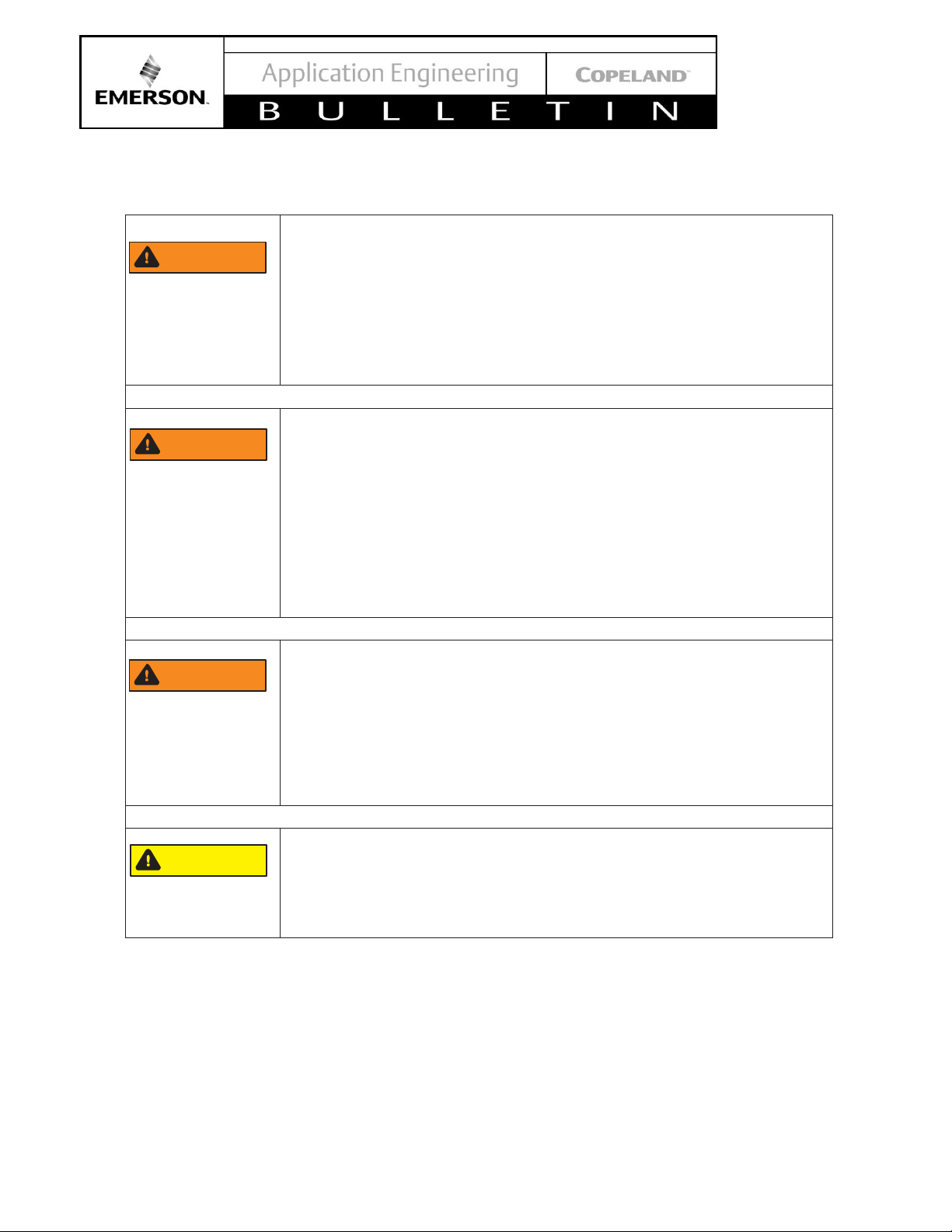
Instructions Pertaining to Risk of Electrical Shock, Fire, or Injury to Persons
ELECTRICAL SHOCK HAZARD
• Disconnect and lock out power before servicing.
• Discharge all capacitors before servicing.
• Use compressor with grounded system only.
• Molded electrical plug must be used when required.
• Refer to original equipment wiring diagrams.
• Electrical connections must be made by qualified electrical personnel.
• Failure to follow these warnings could result in serious personal injury.
PRESSURIZED SYSTEM HAZARD
• System contains refrigerant and oil under pressure.
• Remove refrigerant from both the high and low compressor side before
removing compressor.
• Never install a system and leave it unattended when it has no charge, a
holding charge, or with the service valves closed without electrically locking
out the system.
• Use only approved refrigerants and refrigeration oils.
• Personal safety equipment must be used.
•
Failure to follow these warnings could result in serious personal injury.
BURN HAZARD
• Do not touch the compressor until it has cooled down.
• Ensure that materials and wiring do not touch high temperature areas of the
compressor.
• Use caution when brazing system components.
• Personal safety equipment must be used.
•
Failure to follow these warnings could result in serious personal injury or
property damage.
COMPRESSOR HANDLING
• Use the appropriate lifting devices to move compressors.
• Personal safety equipment must be used.
•
Failure to follow these warnings could result in personal injury or property
damage.
Safety Statements
• Refrigerant compressors must be employed only for their intended use.
• Only qualified and authorized HVAC or refrigeration personnel are permitted to install commission and
maintain this equipment.
• Electrical connections must be made by qualified electrical personnel.
• All valid standards and codes for installing, servicing, and maintaining electrical and refrigeration equipment
must be observed.
CAUTION
WARNING
WARNING
WARNING
Page 4
© 2017 Emerson Climate Technologies, Inc.
4
AE5-1377 R3
1. Introduction
Copeland Scroll™ Outdoor Refrigeration Units provide
the many benefits of scroll compressor technology,
coupled with advanced diagnostic controls, to ensure
reliable performance and operation in foodservice
applications. Electronics are used extensively in its
protection and diagnostic features. These features are
controlled by an electronic integrated control board. The
control board provides base control functions related to
temperature controller, defrost, evaporator fan control,
compressor protection e.g. current overload, phase
reversal, liquid/ vapor injection control, self diagnostics
and warnings. These error codes can be seen by an
LED display for easy and rapid troubleshooting and
maintenance.
A complete product offering for medium and low
temperature units is being offered in single and three
phase 208/230 volts. The -002 and -012 BOM product
is approved for operation in ambients from 120°F to 10°F.
XJAM/XJAL -022 models come factory equipped with a
heated and insulated receiver (thermostat controlled), a
check valve installed between the condenser outlet and
receiver inlet, and a 6 second low pressure control time
delay function.
XJAM/XJAL -022 models are approved to operate in
ambient temperatures below -10°F (-24°C). Laboratory
testing has confirmed successful operation at -30°F (34°C) with the factory supplied low ambient
components. At low ambient conditions, a unit may
recycle on low pressure several times during a restart.
This is normal behavior.
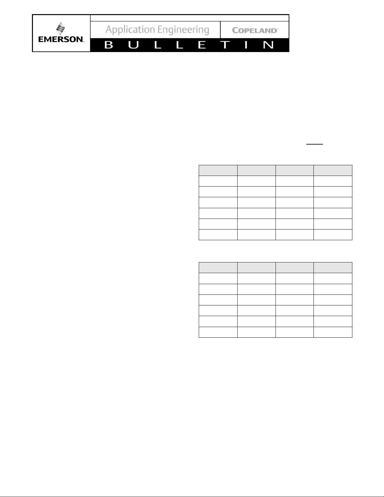
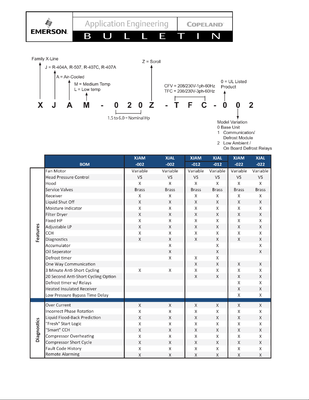
2. Nomenclature/Features
See Figure 1 at the end of this bulletin.
3. Understanding Actual vs. Standard Airflow
To choose the proper coil for your application, the
density of the incoming air needs to be known to
calculate the actual capacity and performance of the
system.
A coil’s required capacity can be calculated using the
thermodynamic equation
Q = M x Delta hr
Q = Heat transfer to or from the air (Btuh)
M = Mass flow rate of air (lb/hr)
Delta h ] Difference between the entering and leaving air
enthalpy or total heat (Btu/lb)
The mass flow rate is equal to the density of air times
the face area of the coil times the velocity of the air at
the coil or face velocity.
M = P x A x V
P = Density (lb/cubic ft.)
A =Face area of coil (square ft.)~Fin height x fin length
V = Air Velocity (ft./min.)
For temperature conversions
(𝑨𝟏)
=
𝟓𝟑𝟎
𝑻+𝟒𝟔𝟎
Table 1 - Temperature Conversion Factors
Temp (°F)
Factor A1
Temp (°F)
Factor A1
0
1.15
60
1.02
10
1.13
70
1.00
20
1.10
80
.98
30
1.08
90
.96
40
1.06
100
.95
50
1.04
110
.93
Table 2 - Altitude Conversion Factors (A2)
Alt (ft.)
Factor A2
Alt (ft.)
Factor A2
0
1.00
3000
.895
500
.982
4000
.864
1000
.965
5000
.832
1500
.947
6000
.802
2000
.930
7000
.771
2500
.912
8000
.743
SCFM= CFM X A1 X A2
Note: all calculations and ratings are based on standard
air at 70°F dry bulb temp and 29.92 Hg atmospheric
pressure (sea level). These tables convert non standard
cfm to standard cfm.
4. Performance Data
See Table 3 and Table 4 at the end of this bulletin.
5. Electrical / Physical Data
See Table 5.
6. Generator Requirements
In situations or locations were an electrical power
generator could be applied in the event of a power
outage, the Copeland Scroll™ outdoor condensing unit
will operate providing the generator will provide a supply
Page 5

© 2017 Emerson Climate Technologies, Inc.
5
AE5-1377 R3
voltage range of 180-260 VAC along with a frequency of
47-63 Hz. The electronics control along with the power
board will function properly providing the range of
operating limits is in compliance!
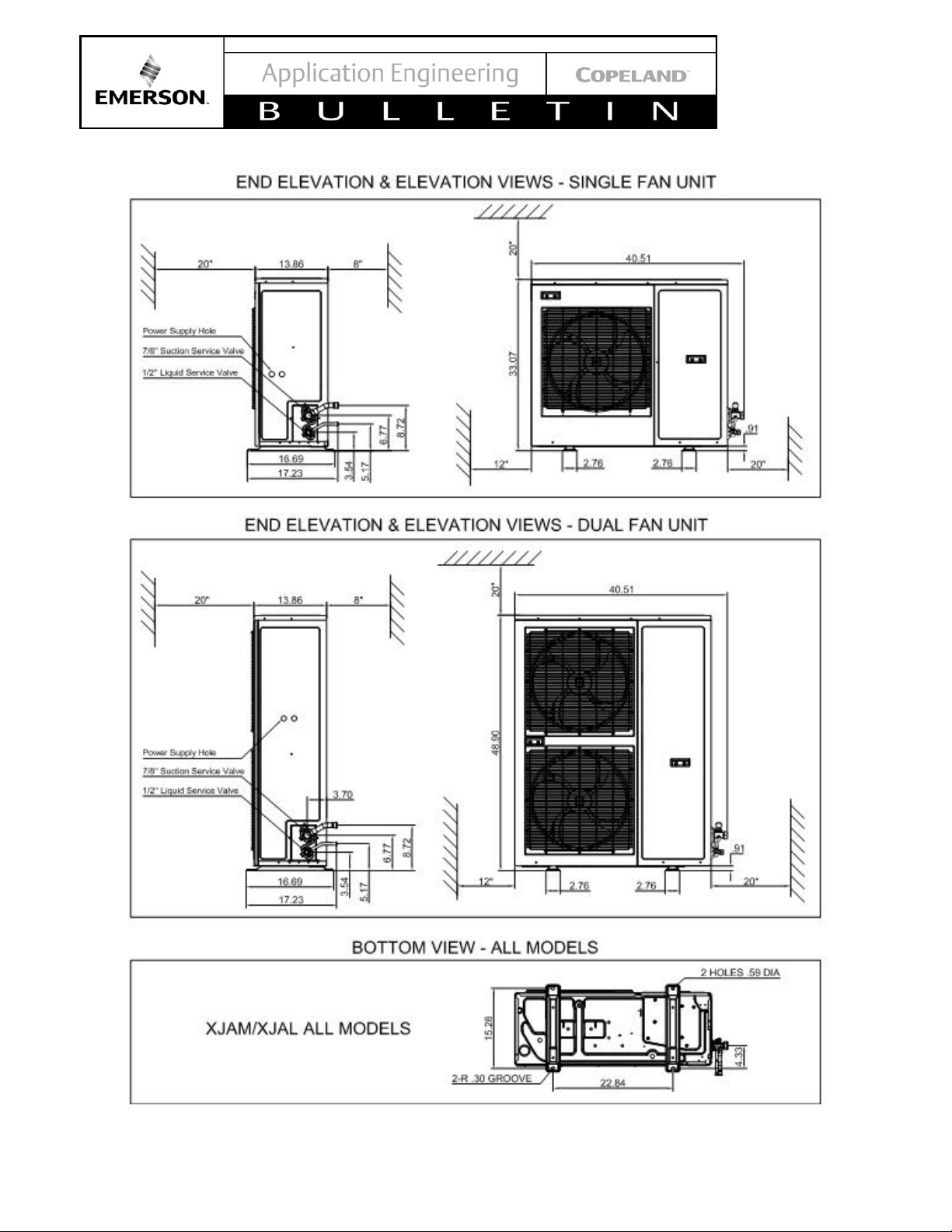
7. Physical Dimensions
See Figure 2.
8. Installation / Piping Instructions
See Figure 2 for overall dimensions of the units. It is
recommended that a clearance of 8 inches from the wall
(or the next unit) be maintained from the unit’s left and
rear panel whereas a clearance of 20 inches is to be
maintained from the unit's right, top and front panels.
Both service access and airflow have been considered
in making these recommendations. Where multiple units
are to be installed in the same location, careful
consideration for proper clearance needs to be given to
each individual unit.
Ideally, the unit should be mounted level on a solid
concrete slab with rubber strips between unit feet and
concrete. However, these units have been designed for
mounting on suitable brackets for wall mounting. In this
case it is equally important that the spatial guidelines
given above are followed, and additional consideration
needs to be given for possible air recycling if units are
stacked above and below each other. In general terms,
air by-pass around each condenser and between each
unit should be avoided at all times.
Pipe sizing should not only be of sufficient size to ensure
optimum performance and good oil return, but it also
needs to take into account the full capacity range
through which this particular unit will need to operate.
Follow the ASHRAE guidelines for proper piping
practices.
9. Condensing Unit Operational Control
The Digital Control electronic control board controls the
operation of the condensing unit. Whenever there is a
control input asking to start or stop the condensing unit,
the control board will execute a set of pre-programmed
procedures to do so. It also monitors the compressor
operating parameters, so as to protect the system from
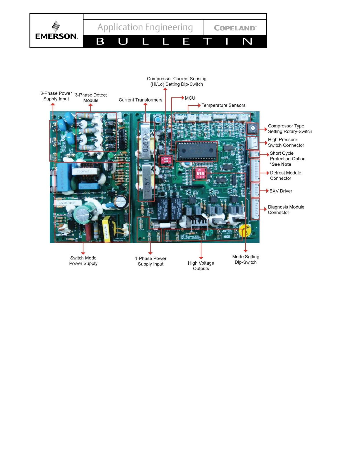
unsafe operating parameters. See Figure 3.
For example, when the low temperature unit
experiences an extreme temperature day, the control
board decides to switch from vapor-injectionoptimization to discharge gas temperature control to
allow the compressor to run safely and pass the extreme
weather hours.
10. Control Features
The base control function is for the following standard
features. See Figure 3 for additional input options and
output options of the control board.
10.1. Fresh Start Program
This Fresh Start Program is a bump start procedure that
will energize and start the compressor for 3 seconds and
then will be followed by a 20 second off cycle time. This
will occur for 3 cycles, and then continuous power will
be supplied to the compressor for normal operation.
The Fresh Start Program will be executed on initial start
up or any time power is reapplied when the ambient
temperature is lower than 95°F. In addition, the Fresh
Start Program will be executed for any start when the
unit has been cycled off for more than an hour when the
ambient temperature is lower than 95°F.
10.2. Stop Program
When the unit is satisfied, or there is any error which
requires the unit to be shut down, the controller will
execute a Stop Program. The compressor and the
condenser fans will cycle off and the injection valves will
close.
For low temperature units only, when the unit is satisfied
the EXV will start closing immediately, but the
compressor will delay 5 seconds before shut down to
prevent reverse rotation of the compressor.
10.3. Automatic Liquid Injection (Medium
temperature units only)
Automatic Liquid Injection ensures that the scroll
compressor operates within a safe temperature limit.
This unit employs a patented liquid injection system
which injects a saturated refrigerant into the suction line
at the compressor. Activation of the liquid injection valve
is in response to a thermistor which is attached to the
compressor discharge line. A signal is sent to the
stepper motor of the injection valve, opening the valve
in response to increasing discharge temperatures and
injecting saturated refrigerant to reduce the discharge
temperature.
10.4. Compressor Phase Reversal
Compressor Phase Reversal senses for the correct
phase sequence on three phase applications. Reset is
automatic once the correct phase sequence is sensed.
An error message will be shown on the diagnostic LED.
Page 6

© 2017 Emerson Climate Technologies, Inc.
6
AE5-1377 R3
10.5. Loss of Phase Protection
If three phase supply is incorrectly connected to the
contactor terminals, or if a missing phase is sensed, an
error message will be shown on the diagnostic LED.
Reset is automatic once the correct phasing is sensed.
10.6. Motor Current Overload
• All scroll compressors used in these condensing
units have an internal inherit motor protector.
• The Copeland Scroll Outdoor Condensing Unit is
also equipped with two current sensors (CT1, CT2)
to monitor the electrical current of the condensing
unit. If the condensing unit current exceeds a predefined current limit, the controller will take the
following actions:
➢ Stop the compressor for 3 minutes
➢ LED signal will display an Over Current Error for 3
minutes
➢ After a 3 minute delay the compressor will go
through a normal start
➢ The system will lock out after 6 over current trips
within an hour
For this function to operate, two of the power leads are
routed through the current sensing coils (CT1, CT2),
prior to the contactor, from the factory. See Figure 3.
10.7. Non-Adjustable High Pressure Control
This pressure sensing device is a nonadjustable, low
voltage pressure switch that will open at 435psig and
reset at 348psig in the event of high discharge pressure.
Its signal is monitored by the control board.
➢ In the event of a high pressure trip, the unit will stop
and then restart after a 3-minute delay.
➢ After 6 successive HP cut-outs within 1 hour, the
unit will lock-out.
➢ The lockout feature can be reset by disconnecting
the power source and then cycling power to the unit.
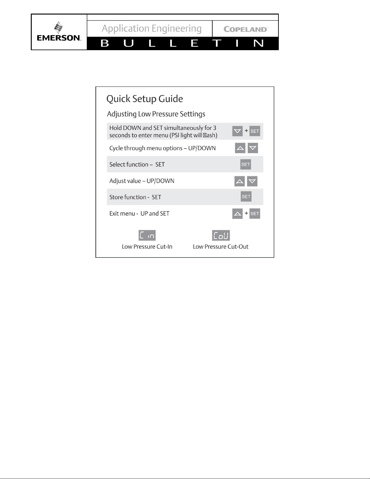
10.8. Adjustable Low Pressure Switch
An adjustable low pressure switch is provided as
standard equipment on both the medium and low
temperature condensing units. This control can be used
for a pump-down cycle if so desired. See Table 10 -
Pressure Control Settings for SJAL/M Units.
Units introduced in mid-2013 include an electronic low
pressure control. The electronic low pressure control
provides more accurate cut-in and cut-out pressure
settings and maintains these settings without drifting
over time. See Figure 7 for setup procedure.
10.9. Liquid Floodback Protection
• Liquid refrigerant entering the compressor during
the run cycle, in excessive quantities, can damage
the compressor by diluting the lubricant, as well as
excessive stress on several components in the
compressor. Proper control of liquid refrigerant
within the system is an application issue and is
beyond control of this controller. However, the
controller can perform checks and alert the user that
liquid refrigerant floodback may be occurring and
immediate field service is required. This is only a
warning signal and will not terminate the operation
of the unit. See Table 6.
• Liquid Floodback Protection is acquired by
monitoring the compressor discharge temperature.
When the discharge line temperature falls below a
specified point, low suction line superheat may be
the cause.
10.10. Crankcase Heater
The crankcase heater is wired through a normally
closed contact of the compressor contactor which is
energized whenever the compressor cycles off.
10.11. Condenser Fan Speed Control
The Condenser Fan Speed Control will vary the speed
of the condenser fan motor for head pressure control
under low ambient conditions. There are two thermistor
type sensors that are connected to the control board.
These sensors monitor the condenser mid coil
temperatures and ambient air temperatures to control
the fan speed.
10.12. Enhanced Vapor Injection (EVI) Control
(Low temperature units only)
The EVI system improves low temperature operational
efficiency and provides a reliable low temperature
envelope. It is used to optimize performance and to
prevent the scroll set from overheating. This is done by
controlling the discharge line temperature (DLT) and
vapor injection superheat (VISH).
Enhanced vapor injection is accomplished by utilizing a
subcooling circuit. A heat exchanger is used to subcool
the liquid refrigerant before it enters the evaporator. As
a result of the subcooling done by the heat exchanger,
refrigerant will also be evaporated. This evaporated
refrigerant is then injected into the mid compression
cycle of the scroll compressor for overheat temperature
control.
Page 7

© 2017 Emerson Climate Technologies, Inc.
7
AE5-1377 R3
There are two thermistors sensing the discharge line
temperature, one is located at the discharge line of the
compressor and the second one is placed at the inlet of
the condenser coil. In order to have a higher
temperature resolution, the discharge line thermistor
and condenser coil inlet sensor cooperate to sense a
temperature range from 50°F to 329°F. The discharge
line thermistor has a sensing range from 163°F to 329°F
and the condenser coil will sense temperature from 50°F
to 176°F. The EVI system will keep the discharge line
temperature below 230°F to ensure the safety of the
compressor.
It is important to insulate the system liquid line from the
condensing unit to the evaporator. The recommended
insulation thickness is a minimum of ½ inch. Also the
lower liquid temperature can increase the evaporator
expansion valve capacities. Please follow the valve
manufactures recommended liquid temperature
correction factors for proper selection of the evaporator
expansion valve.
11. Electronic Expansion Value (EXV)
The Electronic Expansion Value (EXV) is a key part of
the EVI system. It will regulate vapor injection flow to
optimize the performance of system and cool the scroll
set. Every second, the control chip will collect the
thermistors reading and do a four second averaging.
The EXV opening will be changed every 20 seconds and
the variation is calculated by different ways based on
different purposes.
12. TXV selection
For EVI, Emerson recommends a balanced port TXV
because it offers a wider operating range for floating
liquid temperatures.
See Table 9 for specifics regarding balanced port sizing
recommendations. Applied with the low temp units it is
recommended that a balanced port expansion valve be
used along with a complete review of the the distributor
& nozzle (orifice) that is supplied with the Evaporator coil
being matched with the applicable condensing unit.
Typically nozzles are selected for standard TXV sizing
using 100°F liquid, with the XJAL those typical
selections could be grossly oversized. See Table 9 for
the liquid correction safety factors when selecting those
components.
13. Other Inputs to the Control Board
13.1. Customer Supplied Control (Thermostat)
The control board will accept a normal 220 volt AC input
ON/OFF signal such as the switching action of a normal
commercial thermostat and relay. If the system is
controlled by low pressure control for a multiple
evaporator system and/or pump down system, the
control board will accept the signal directly from the
control. See Wiring Diagrams, for proper installation.
14. Other Outputs from the Control Board
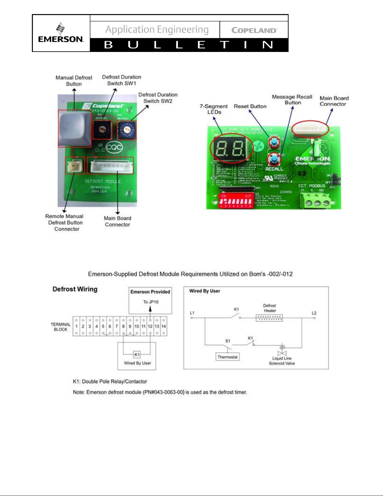
14.1. Defrost Control Board for Units Produced
Prior to Mid- 2013
(using the control module shown in Figure 4.) The
defrost control board is a basic time initiated module
which is standard on both low and medium temperature
units. The defrost control board can control either offcycle or electric defrost.
The defrost control board will control the liquid line
solenoid valve. When defrost is initiated the liquid line
solenoid valve will close and the unit will go into a
pumpdown cycle. When the suction pressure equals the
setting of the low pressure control, the compressor will
cycle off. After the defrost time has expired, the liquid
line solenoid valve opens and then
the low pressure control will allow the compressor to
restart.
On -002 and -012 models only, due to heater amperage
loads, electric defrost requires an additional relay or
contactor to energize the defrost heater. Relays capable
of 30 amp loads are supplied on the -022 models
The defrost cycle can be executed either automatically
or manually. There are two rotary dip switches by which
the user can set up the defrost cycle, see Figure 4. One
rotary dipswitch sets the defrost duration (SW1) and the
second rotary dipswitch sets the time interval between
defrost cycles (SW2). For automatic defrost set SW1
and SW2 as desired. See Table 6 for time settings. The
defrost control board also incorporates a manual defrost
button that enables a manual defrost as an override to
the rotary switch setting the defrost interval. Upon the
completion of a manual defrost, the system will reset to
the refrigeration cycle with the same procedures as
automatic defrost and then the automatic defrost timer
will reset.
For setting manual defrost only set SW1 as desired and
set SW2 to “0”. Whenever the manual defrost button is
pressed, one defrost cycle will be executed and the
duration of defrost will be determined by the setting of
the rotary dipswitch SW1.
Note: There is no method to terminate a defrost cycle
without resetting the control board.
Table 6 lists rotary dip switch settings for the Defrost
Control Board.
An ON/OFF output connection is provided on the control
board (JP10) for direct connection of a customer
Page 8

© 2017 Emerson Climate Technologies, Inc.
8
AE5-1377 R3
supplied contactor coil/relay when the defrost option is
used. Terminals are male spade type. Coil voltage rating
should be 220VAC and current ratings, 30VA (hold) and
330VA (inrush). See Figure 6.
For customers using their existing defrost timer, remove
the defrost cable connecting the defrost control board to
the unit control board. Also on the unit control board
change the mode setting dip-switch bit 2 to ON and
proceed to standard defrost wiring. See Table 7.
15. Updated Defrost Control Module
Models produced after mid 2013 include an updated
electronic control module that allows for both interval
based defrost or real time based defrost. See Figure 7
for quick setup guide. See Appendix 2, Defrost
Quickstart, for detailed information.
16. Evaporator Fan Control
An ON/OFF output connection is also provided on the
control board (JP9) for direct connection of a customer
supplied contactor coil controlling the evaporator fans.
Terminals are the male spade type. Coil voltage rating
is to be 220VAC and a maximum power rating of 30VA
(hold) and 330VA (inrush). See Figure 6.
17. Diagnostic Display Board
Each condensing unit is supplied with a one-way
communications and diagnostic display board, see
Figure 5. A two character display will make up the
diagnostic/error code. The first character will display the
unit status as shown in Table 8. The second character
will display the error/warning code as shown in Table 8.
See Figure 5 for a detailed view of the diagnostics
board assembly.
The Main Board Connector terminal will accept the
cable connecting the display board to the main control
board. The Reset Button will reset the diagnostic display
board only. The Message Recall Button will display the
last error signal received by the display board. See
Figure 5.
Page 9
© 2017 Emerson Climate Technologies, Inc.
9
AE5-1377 R3
Figure 1 - Nomenclature and Features
Page 10
© 2017 Emerson Climate Technologies, Inc.
10
AE5-1377 R3
Figure 2 - Physical and Installation Requirements
Page 11
© 2017 Emerson Climate Technologies, Inc.
11
AE5-1377 R3
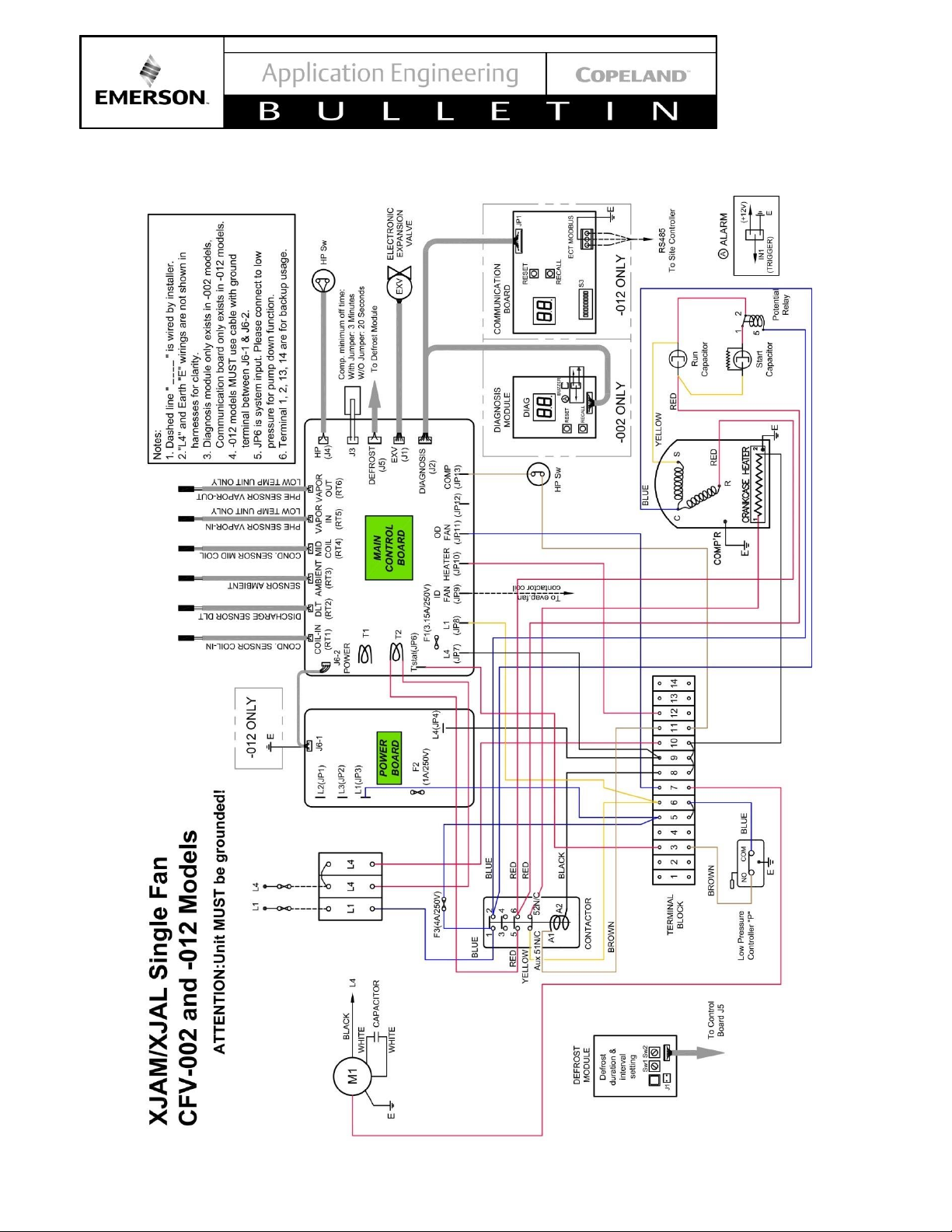
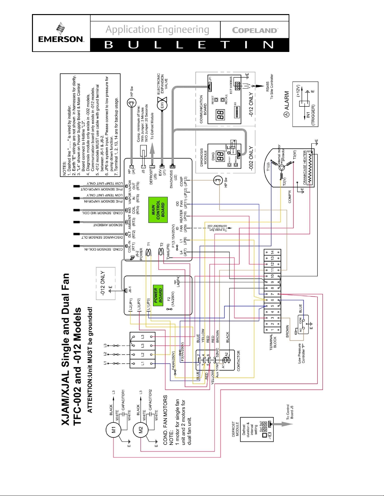
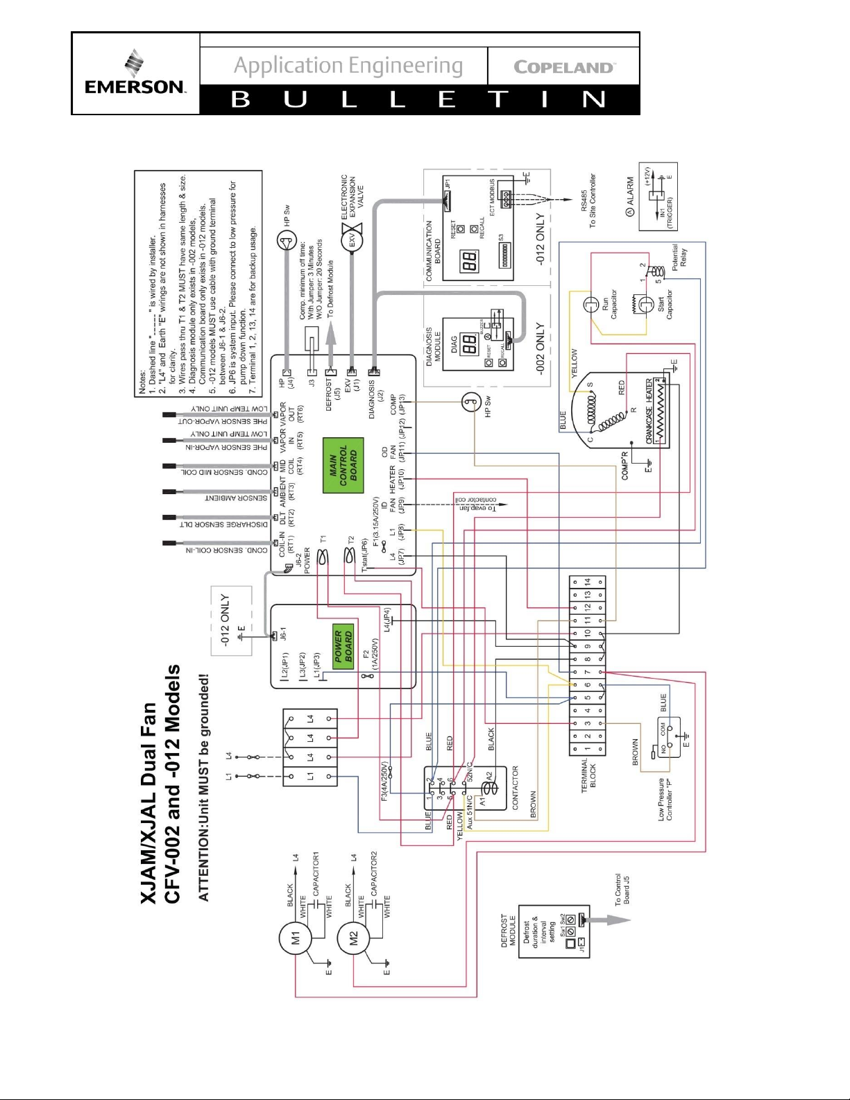
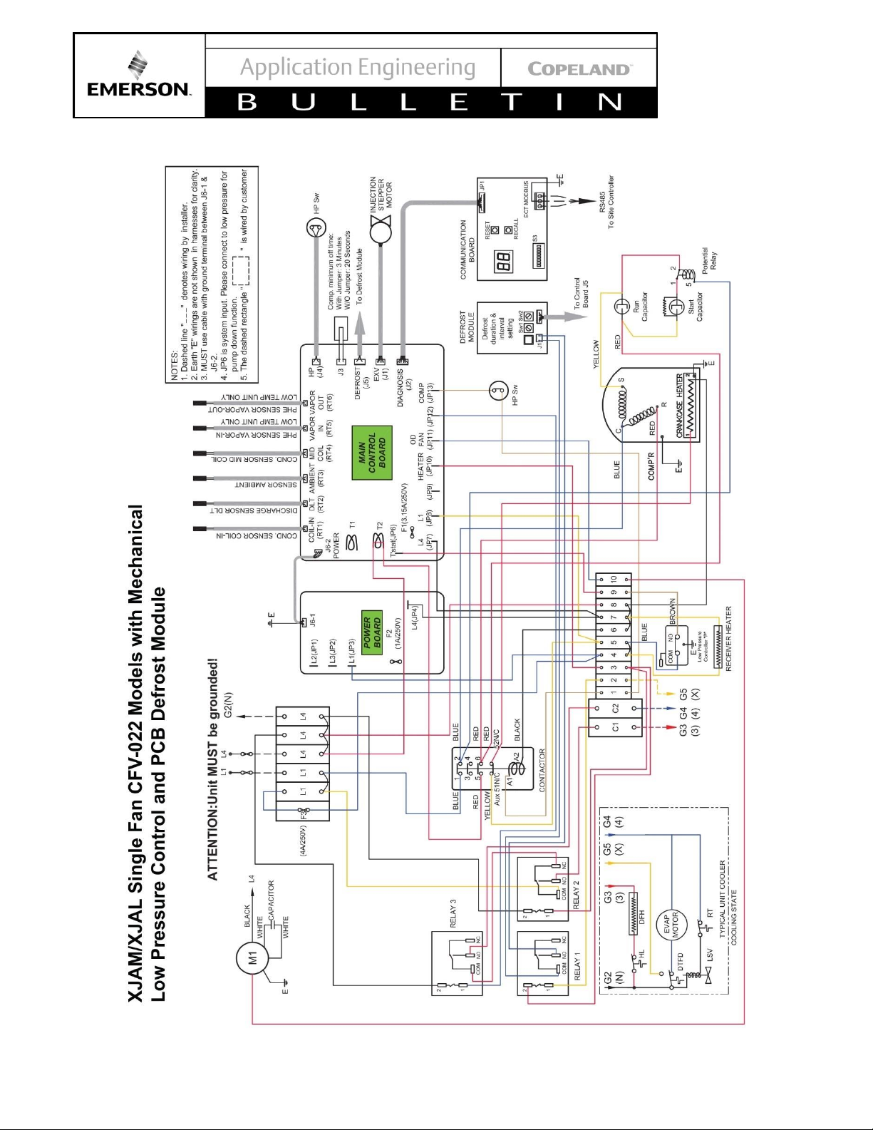
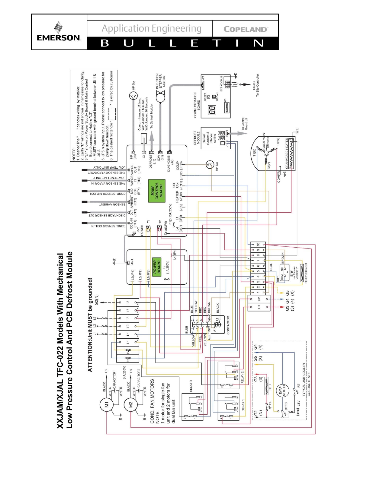
Figure 3 - Power Board / Control Board
* Note: Short Cycle Protection Option
a. Factory Jumper Intalled Three Minute Time Delay
b. Remove Jumper Twenty Second Time Delay
Page 12
© 2017 Emerson Climate Technologies, Inc.
12
AE5-1377 R3
Figure 4 - Defrost Control Module
Figure 5 - Communication Board
Figure 6 - Emerson Supplied Defrost (-002/-012 Models Only)
Page 13
© 2017 Emerson Climate Technologies, Inc.
13
AE5-1377 R3
Figure 7 - Quick Setup Guide for Electronic Low Pressure Control
Page 14
© 2017 Emerson Climate Technologies, Inc.
14
AE5-1377 R3
Drawings
Page 15
© 2017 Emerson Climate Technologies, Inc.
15
AE5-1377 R3
Page 16
© 2017 Emerson Climate Technologies, Inc.
16
AE5-1377 R3
Page 17
© 2017 Emerson Climate Technologies, Inc.
17
AE5-1377 R3
Page 18
© 2017 Emerson Climate Technologies, Inc.
18
AE5-1377 R3
Page 19

© 2017 Emerson Climate Technologies, Inc.
19
AE5-1377 R3
Page 20

© 2017 Emerson Climate Technologies, Inc.
20
AE5-1377 R3
Page 21

© 2017 Emerson Climate Technologies, Inc.
21
AE5-1377 R3
Page 22

© 2017 Emerson Climate Technologies, Inc.
22
AE5-1377 R3
Page 23

© 2017 Emerson Climate Technologies, Inc.
23
AE5-1377 R3
Page 24

© 2017 Emerson Climate Technologies, Inc.
24
AE5-1377 R3
Table 3 - Medium Temp Performance Criteria for R-404A
For other approved refrigerant performance data, visit Online Product Information at Emerson.com/OPI
H.P.
Medium Temperature
Model Number
Btu/hr @ +25°F Sat. Suction
Temp / 90°F Ambient
Btu/hr @ +25°F Sat. Suction
Temp / 100°F Ambient
Refrigerant/
Oil Type
1.5 XJAM-015Z-CFV
14600
13600
R404A / POE
2 XJAM-020Z-CFV
19600
17900
R404A / POE
2 XJAM-020Z-TFC
19600
17900
R404A / POE
3 XJAM-030Z-CFV
28500
25900
R404A / POE
3 XJAM-030Z-TFC
28500
25900
R404A / POE
4 XJAM-040Z-CFV
38600
35300
R404A / POE
4 XJAM-040Z-TFC
38600
35300
R404A / POE
5 XJAM-050Z-CFV
47100
43800
R404A / POE
5 XJAM-050Z-TFC
47100
43800
R404A / POE
6 XJAM-060Z-TFC
54600
50200
R404A / POE
Table 4 - Low Temp Performance Criteria for R-404A
For other approved refrigerant performance data, visit Online Product Information at Emerson.com/OPI
H.P.
Low Temperature
Model Number
Btu/hr @ -10°F Sat. Suction
Temp / 90°F Ambient
Btu/hr @ -10°F Sat. Suction
Temp / 100°F Ambient
Refrigerant/
Oil Type
2 XJAL-020Z-CFV
13100
12700
R404A / POE
2 XJAL-020Z-TFC
13100
12700
R404A / POE
3 XJAL-030Z- TFC
17200
16400
R404A / POE
3 XJAL-035Z- CFV
19700
18100
R404A / POE
4 XJAL-040Z-CFV
24700
23700
R404A / POE
4 XJAL-040Z-TFC
24700
23700
R404A / POE
5 XJAL-050Z-CFV
27600
25700
R404A / POE
5 XJAL-050Z-TFC
27600
25700
R404A / POE
6 XJAL-060Z-TFC
34700
32700
R404A / POE
Page 25

© 2017 Emerson Climate Technologies, Inc.
25
AE5-1377 R3
Table 5 - Mechanical/Electrical Specifications
Unit Model
Compressor
H.P.
Dimensions (in)
Connection Lines
#
of
Fans
Min Circuit Ampacity/
Max Fuse (Amps)
Pump
Down
Capacity
(lbs)
Unit
Weight
(lbs)
dba *
L W H Suction
Liquid
208/230V
1ph-60hz
208/230V
3ph-60hz
XJAM-015Z
ZS11KAE
1.5 16.7 40.5 33
3/4"
Pre mid-2013
7/8"
Post mid-2013
1/2 " 1 15.2 / 20
N/A 7.5 180 55
XJAM-020Z
ZX15KCE
2 16.7 40.5 33
3/4"
Pre mid-2013
7/8"
Post mid-2013
1/2 " 1 18.7 / 30
11.1 / 15
7.5 182 55
XJAM-030Z
ZX21KCE
3 16.7 40.5 33
3/4"
Pre mid-2013
7/8"
Post mid-2013
1/2 " 1 24.3 / 40
14.7 / 25
7.5 194 55
XJAM-040Z
ZX30KCE
4 16.7 40.5 49 7/8 "
1/2 " 2 32.1 / 50
19.7 / 30
11
250 56
XJAM-050Z
ZX38KCE
5 16.7 40.5 49 7/8 "
1/2 " 2 36.6 / 60
29.0 / 50
11
258 56
XJAM-060Z
ZX45KCE
6 16.7 40.5 49 7/8 "
1/2 " 2 N/A
28.1 / 45
11
270 56
XJAL-020Z
ZXI06KCE
2 16.7 40.5 33
3/4"
Pre mid-2013
7/8"
Post mid-2013
1/2 " 1 19.4 / 30
14.7 / 25
7.5 188 50
XJAL-030Z
ZXI09KCE
3 16.7 40.5 33
3/4"
Pre mid-2013
7/8"
Post mid-2013
1/2 " 1 N/A
15.4 / 25
7.5 192 50
XJAL-035Z
ZXI11KCE
3.5 16.7 40.5 33 7/8 "
1/2 " 1 30.7 / 50
N/A 7.5 213 50
XJAL-040Z
ZXI14KCE
4 16.7 40.5 49 7/8 "
1/2 " 2 36.1 / 60
24.5 / 40
11
251 58
XJAL-050Z
ZXI15KCE
5 16.7 40.5 49 7/8 "
1/2 " 2 N/A
26.1 / 45
11
267 58
XJAL-050Z
ZXI16KCE
5 16.7 40.5 49 7/8 "
1/2 " 2 40.4 / 70
N/A 11 287 58
XJAL-060Z
ZXI18KCE
6 16.7 40.5 49 7/8 "
1/2 " 2 N/A
30.7 / 50
11
291 58
Assume Each Fan @ .75 Amps
*Estimated sound pressure values are 10 feet from the unit at 25F evap for MT and -10 evap for LT at 90 ambient. A sound reduction of up to 3
dBA will occur in ambient temperatures below 70F. This data is typical of ‘free field’ conditions for horizontal air cooled condensing units and
may vary depending on the condensing unit installation. There are many factors that affect the sound reading of a condensing unit such as unit
mounting, reflecting walls, background noise and operating condition.
Table 6 - Emerson Supplied Defrost Set Points
For Models with Mechanical Low Pressure Control and PCB Defrost Module
Switch 1
Defrost duration (minutes)
Switch 2
Time interval between defrost
0
No defrost (manual defrost only)
0
No defrost (manual defrost only)
1
5 minutes
1
1 hour
2
10 minutes
2
2 hours
3
15 minutes
3
3 hours
4
20 minutes
4
4 hours
5
25 minutes
5
5 hours
6
30 minutes
6
6 hours
7
35 minutes
7
7 hours
Page 26

© 2017 Emerson Climate Technologies, Inc.
26
AE5-1377 R3
Table 7 - Main Control Board Settings
XJAM
Unit Model
Compressor
Name**
Rotary
Switch
2bit Dip-
Switch
3bit Dip Switch
Control Board
Default Setting
0
ON/ON
Bit1: To set evaporator fan control mode
"OFF": Evaporator Fan On/Off Logic Same As
Compressor
"ON": Evaporator fan will be ON all the time no matter
whether compressor is ON/OFF or defrosting
Bit2: To set defrost mode
"OFF": default setting, using Emerson defrost module
"ON": Using Customer defrost module
Bit3: Not Used Yet
XJAM-015Z-CFV
ZS11KAE-PFV
A
ON/ON
XJAM-020Z-TFC
ZX15KCE-TF5
1
ON/ON
XJAM-020Z-CFV
ZX15KCE-PFV
2
ON/ON
XJAM-030Z-TFC
ZX21KCE-TF5
3
ON/ON
XJAM-030Z-CFV
ZX21KCE-PFV
4
OFF/OFF
XJAM-040Z-TFC
ZX30KCE-TF5
5
ON/ON
XJAM-040Z-CFV
ZX30KCE-PFV
6
OFF/OFF
XJAM-050Z-TFC
ZX38KCE-TF5
7
OFF/OFF
XJAM-050Z-CFV
ZX38KCE-PFV
8
OFF/OFF
XJAM-060Z-TFC
ZX45KCE-TF5
9
OFF/OFF
XJAL
Unit Model
Compressor
Name**
Rotary
Switch
2bit Dip-
Switch
3bit Dip Switch
Control Board
Default Setting
0
ON/ON
Bit1: To set evaporator fan control mode
"OFF": Evaporator Fan On/Off Logic Same As
Compressor
"ON": Evaporator fan will be ON all the time no matter
whether compressor is ON/OFF or defrosting
Bit2: To set defrost mode
"OFF": default setting, using Emerson defrost module
"ON": Using Customer defrost module
Bit3: Not Used Yet
XJXL-020Z-TFC
ZXI06KCE-TF5
1
ON/ON
XJXL-020Z-CFV
ZXI06KCE-PFV
2
ON/ON
XJXL-030Z-TFC
ZXI09KCE-TF5
3
ON/ON
XJXL-035Z-CFV
ZXI11KCE-PFV
4
OFF/OFF
XJXL-040Z-TFC
ZXI14KCE-TF5
5
OFF/OFF
XJXL-040Z-CFV
ZXI14KCE-PFV
6
ON/ON
XJXL-050Z-TFC
ZXI15KCE-TF5
7
OFF/OFF
XJAM-050Z-TFC
ZX38KCE-TF5
7
OFF/OFF
XJAM-050Z-CFV
ZX38KCE-PFV
8
OFF/OFF
XJAM-060Z-TFC
ZX45KCE-TF5
9
OFF/OFF
**Please set the switches to the correct position according to compressor model.
Page 27

© 2017 Emerson Climate Technologies, Inc.
27
AE5-1377 R3
Table 8 - Diagnostics Module Display
LED1 – Unit Status
Display
Status
Idle (Set Point or Low Pressure Cut-Out Rached)
Run
About to Start1
Defrost
Unit Trip
Unit Lockout
LED1 – Unit Status
Display
Status
No error/warnings
Compressor Phase Error (Wrong Phase Sequence/Loss of
Phase)
Compressor Inside Internal Motor Protector Trip
Compressor Over Current
Discharge Gas Overheat (High Discharge Temperature)
Compressor High Pressure Cut Out
Not Used
DLT Thermistors Failure
Ambient Temperature Sensor Failure
Mid-coil Temperature Sensor Failure
PHE Vapor In Temperature Sensor Failure or over range2
PHE Vapor Out Temperature Sensor Failure or over range2
System Liquid Flood Back Warning
Notes:
1
This signal is for Fresh Start, Normal Start Program and any start request delay.
2
PHE Vapor In/Out Temperature Sensor is not applicable in XJAM condensing unit (MT units).
All error/warning messages are priority-ranked from highest to lowest. If unit is initially powered on, the diagnosis
module will show signal similar to the below example:
Figure 8 - Diagnostics Module Start Up Information
Page 28

© 2017 Emerson Climate Technologies, Inc.
28
AE5-1377 R3
Table 9 - Refrigerant Liquid Temperature Valve Capacity Multiplier Correction Factors
Refrigerant Liquid Temperature °F
0
10
20
30
40
50
60
70
80
90
100
110
120
130
140
R-12
Correction Factor
1.60
1.54
1.48
1.42
1.36
1.30
1.24
1.18
1.12
1.06
1.00
0.94
0.88
0.82
0.75
R-134a
Correction Factor
1.70
1.63
1.56
1.49
1.42
1.36
1.29
1.21
1.14
1.07
1.00
0.93
0.85
0.78
0.71
R-22
Correction Factor
1.56
1.51
1.45
1.40
1.34
1.29
1.23
1.17
1.12
1.06
1.00
0.94
0.88
0.82
0.76
R-404A/R-507
Correction Factor
2.00
1.90
1.80
1.70
1.60
1.50
1.40
1.30
1.20
1.10
1.00
0.90
0.80
0.70
0.50
These factors include corrections for liquid refrigerant density and net refrigerating effect and are based on an
average evaporator temperature of 0°F. However, they may be used for any evaporator temperature from - 40°F to
+ 40°F since the variation in the actual Factors across this range is insignificant.
Table 10 - Pressure Control Settings for SJAL/M Units
Application
Control
R-404A/R-507
R-407A
R-407C
XJAL(Low Temp)
Low Pressure
0 PSIG min.
N/A
N/A
XJAM(Medium
Temp)
Low Pressure
17 PSIG min.
26.9 PSIG min.
9.4 PSIG min.
Page 29

© 2017 Emerson Climate Technologies, Inc.
29
AE5-1377 R3
Table 11 - System Diagnostic Information
Code
Character
1
Code
Character
2
Fault Type
Trip to Set Point
Control Board
Actions
Auto
Resets
Possible Error and Solution
0
0
Low Pressure
Cutout
Loss of Low
Pressure Control
Signal
- Stop the Unit
Auto Start
Suction Pressure below Cutout Set
Point, normal operation for pump down
system control. Unit in standby mode of
operation
1
0
No Fault
No Fault
No Action
Run
No Fault, Unit Running
1
2
Electrical
Failure
Compressor intends
to start but current
transducers on main
control board sense
no current
-Display compressor
protector trip on
diagnostic
-Auto Start When
protector resets
Auto Start
-Verify proper system voltage at the
compressor
-Verify start component operation ( if
single phase )
-Verify all phases are present, ( three
phase ) verify operation of the unit
contactor.
1
7
Discharge
Line And Coil
in Temp
Sensors
Failure
(See Table
12)
-Actual DLT>320°F
~DLT Sensor Fails
and actual DLT>
176°F
-Both coil-in and DLT
sensors fail (short
circuit)
-Coil Sensor fails
(open) and actual
DLT is <163°F
-Display DLT sensor
failure on diagnostic
-Continue to run the
unit on default mode
Run
-Verify proper connection at the main
control board
-Verify the resistance of the two
sensers See Table 12
1
8
Ambient
Temperature
Sensor Failure
(See Table
12)
Ambient sensor
reads < -22°F or
>145°F
-Display ambient temp
sensors failure on
diagnostic
-Continue to run the
unit on default mode.
Run
-Verify proper connection at the main
control board
-Verify the resistance of the sensor.
See Table 12
1
9
Condensor
Mid-Coil
Sensor Failure
(See Table
12)
Mid-coil sensor
reads < -22°F or
>145°F
-Display mid-coil temp
sensors failure on
diagnostic
-Continue to run the
unit on default mode.
Run
-Verify proper connection at the main
control board
-Verify the resistance of the senser
See Table 12
1
A
PHE vapor in
sensor failure
(Only in XJAL
CDU)
(See Table
12)
-Vapor in sensor
reads <3.2°F or
>163°F
-Ambient temp reads
>50°F
-Display sensor error
on diagnostics
-Continue to run unit
on default mode
Run
-Check whether actual temperature is
out of range
-Check whether the sensor is
connected to the control board
-Check whether the sensor is mounted
at the right position
-Check whether the sensor is in the
heat isolation material
-Check whether the sensor has failed
Page 30

© 2017 Emerson Climate Technologies, Inc.
30
AE5-1377 R3
Code
Character
1
Code
Character
2
Fault Type
Trip to Set Point
Control Board
Actions
Auto
Resets
Possible Error and Solution
1
C
PHE vapor out
sensor failure
(Only in XJAL
CDU)
(See Table
12)
-Vapor out sensor
reads <3.2°F or
>163°F
-Ambient temp reads
>50°F
-Display sensor error
on diagnostics
-Continue to run unit
on default mode
Run
-Check whether actual temperature is
out of range
-Check whether the sensor is
connected to the control board
-Check whether the sensor is mounted
at the right position
-Check whether the sensor is in trhe
heat isolation material
-Check whether the sensor has failed
2
0
Compressor
Rapid Cycling
See Page 8.
Minimum off time
can be selected via
jumper setting
-Delay compressor
start, if minimum off
time is less than 3 min
-Display about to turn
on diagnostic
Auto Start
-Compressor start signal is active when
unit stops; the only thing needed to do
is wait until the unit starts
Fresh Start
Occurs on:
-initial unit start,
-When power is reset
<95°F ambient
Compressor is
cycled off > than 1
hour < than 95° F
ambient
-Compressor runs 3
sec and stops 20 sec
-After 3 cycles,
compressor runs
continously
-Display fresh start on
diagnostic
Auto Start
No faults detected, unit about to start.
2
1
Reverse
Phase/Loss of
phase
(3 phase only)
Incorrect phase
sequence
-Stop the unit
-Display the incorrect
phase
-Display waiting to
restart on diagnostic
-Check the phase
sequence after 3
minutes
Auto Start
Compressor Phase Reversal senses
for the correctphase sequence on three
phase applications. Reset is automatic
once the correct phase sequence is
sensed.An error message will be
shown on the diagnostic LED.
2
3
Over Current
Set based on
Compressor
-Stop the Unit
-Display over current
trip on diagnostic
-Display waiting to
restart on diagnostic
-Auto start the unit
after 3 minutes
-Lockout unit if 6 trips
in less than 12 hour
5 Auto
Starts in 1
Hour
* Check rotary switch, make sure it is
on the right position according to the
unit model, Reference Table 7
* Check system operating pressures
* Check voltage supply at the
compressor terminals, must be with in
the +/- 10% voltage tolerance of the
comprressor nameplate.
Page 31

© 2017 Emerson Climate Technologies, Inc.
31
AE5-1377 R3
Code
Character
1
Code
Character
2
Fault Type
Trip to Set Point
Control Board
Actions
Auto
Resets
Possible Error and Solution
2
4
Discharge Gas
Overheat
Discharge
Temperatures over
270°F
-Stop the Unit
-Display DLT trip on
diagnostic
-Display waiting to
restart on diagnostic
-Auto start the unit
after 3 minutes
-Lockout unit if 6 trips
within 1 hour
5 Auto
Starts in 1
hour
-Verify system operations to be with in
unit pressure / temperature envelope of
the unit
-Review return gas temperatures at the
compressor.
2
5
High Pressure
Trip
-Contact open at 435
psig ±22psig
-Contact Close at
348 psig ±22psig
-Stop the Unit
-Display HP trip on
diagnostic
-Display waiting to
restart on diagnostic
-Auto start the unit
after 3 minutes
-Lockout unit if 6 trips
within 1 hour
5 Auto
Starts in 1
Hour
-Check fan motor / blade operations,
verify wiring of the system.
-Blocked condenser, air re-circulation ,
Non Condensables
-Check liquid line solenoid valve, liquid
service valve, make sure they are open
2
7
Discharge
Line And Coil
in Temp
Sensors
Failure
(See Table
12)
-Actual DLT>320°F
~DLT Sensor Fails
and actual DLT>
176°F
-Both coil-in and DLT
sensors fail (short
circuit)
(Only in XJAL)
-Stop the unit
-Display DLT sensor
failure on the
diagnostic
-Display waiting to
restart on diagnostic
-Auto start the unit
after 3 minutes
Auto Start
-Verify proper connection at the main
control board
-Verify the resistance of the two
sensers See Table 12
4
1
Reverse
Phase/Loss of
phase
(3 phase only)
Incorrect Voltage
sequence
-Stop the unit
-Display the incorrect
phase
-Display waiting to
restart on diagnostic
-Check the phase
sequence after 3
minutes
Auto Start
-Check Voltage sequence of the Power
board, see wiring diagram for
applicable sequence. Verify voltage
sequence at line side of unit terminal
block. See wiring diagram
4
3
Over Current
Set based on
Compressor
-Stop the Unit
-Display over current
trip on diagnostic
-Auto start the unit
after 3 minutes
-Lockout unit if 6 trips
in less than 12 hour
5 Auto
Starts in 1
Hour
* Check rotary switch, make sure it is
on the right position according to the
unit model, Reference Table 7
* Check system operating pressures
* Check voltage supply at the
compressor terminals, must be with in
the +/- 10% voltage tolerance of the
compressor nameplate.
Page 32

© 2017 Emerson Climate Technologies, Inc.
32
AE5-1377 R3
Code
Character
1
Code
Character
2
Fault Type
Trip to Set Point
Control Board
Actions
Auto
Resets
Possible Error and Solution
4
4
Discharge Gas
Overheat
Discharge
Temperatures over
270°F
-Stop the Unit
-Display DLT trip on
diagnostic
-Auto start the unit
after 3 minutes
-Lockout unit if 6 trips
within 1 hour
5 Auto
Starts in 1
hour
-Check system operations, for example
condensing pressures, return gas
temperatures, envelope operations etc.
Verify operations and correct the
situation
4
5
High Pressure
Trip
-Contact open at 435
psig ±22psig
-Contact Close at
348 psig ±22psig
-Stop the Unit
-Display HP trip on
diagnostic
-Auto start the unit
after 3 minutes
-Lockout unit if 6 trips
within 1 hour
-Display HP lockout on
diagnostic
5 Auto
Starts in 1
Hour
-Verify condenser fan operation,
excessive air recirculation, excessive
ambient temperatures, incorrect
envelope operations
-Verify system component operations
5
3
Over Current
Set based on
Compressor
-Stop the Unit
-Display over current
trip on diagnostic
-Lockout unit if 6 trips
in less than 12 hour
-Display over current
lockout on diagnostic
Lockout
* Check rotary switch, make sure it is
on the right position according to the
unit model, Reference Table 7
* Check system operating pressures
* Check voltage supply at the
compressor terminals, must be with in
the +/- 10% voltage tolerance of the
compressor nameplate.
5
4
Discharge Gas
Overheat
(XJAM
Models)
Discharge
Temperatures over
270°F
-Stop the Unit
-Display DLT trip on
diagnostic
-Lockout unit if 6 trips
within 1 hour
-Display DLT overheat
lockout on diagnostic
Lockout
-Check system operations, for example
condensing pressures, return gas
temperatures, envelope operations etc.
Verify operations and correct the
situation
5
5
High Pressure
Trip
-Contact open at 435
psig ±22psig
-Contact Close at
348 psig ±22psig
-Stop the Unit
-Display HP trip on
diagnostic
-Lockout unit if 6 trips
within 1 hour
-Display HP lockout on
diagnostic
Lockout
-Verify condenser fan operation,
excessive air recirculation, excessive
ambient temperatures, incorrect
envelope operation
-Verify system component operations
Page 33

© 2017 Emerson Climate Technologies, Inc.
33
AE5-1377 R3
Table 12 - Sensor Information
In the event there is fault code referencing a possible issue with any one of the four unit control temperature sensors,
see this table to assess the fault code condition. If the resistance of the sensor in question does not compare to the
information provide in the table for the applicable sensor, then that sensor will need replaced.
DLT
Coil-in
Amb/Mid-Coil
VIT/VOT
Temp
Temp
R
Temp
Temp
R
Temp
Temp
R
Temp
Temp
R
140
60
22.99
50
10
207.6
-22
-30
121.9
5
-15
56.48
142
61
22.13
52
11
197.2
-20
-29
115.5
7
-14
53.78
144
62
21.31
54
12
187.5
-18
-28
109.5
9
-13
51.24
145
63
20.51
55
13
178.4
-17
-27
103.9
10
-12
48.84
147
64
19.78
57
14
169.7
-15
-26
98.54
12
-11
46.56
149
65
19.06
59
15
161.5
-13
-25
93.52
14
-10
44.4
151
66
18.36
61
16
153.7
-11
-24
88.78
16
-9
42.36
153
67
17.7
63
17
146.4
-9
-23
84.32
18
-8
40.42
154
68
17.06
64
18
139.4
-8
-22
80.1
19
-7
38.58
156
69
16.45
66
19
132.8
-6
-21
76.12
21
-6
36.84
158
70
15.87
68
20
126.6
-4
-20
72.38
23
-5
35.08
160
71
15.31
70
21
120.6
-2
-19
68.82
25
-4
33.62
162
72
14.78
72
22
115.1
0
-18
65.48
27
-3
32.12
163
73
14.26
73
23
109.8
1
-17
62.3
28
-2
30.7
165
74
13.77
75
24
104.7
3
-16
59.3
30
-1
29.36
167
75
13.29
77
25
100
5
-15
56.48
32 0 28.08
169
76
12.83
79
26
95.47
7
-14
53.78
34 1 26.86
171
77
12.39
81
27
91.19
9
-13
51.24
36 2 25.7
172
78
11.97
82
28
87.1
10
-12
48.84
37 3 24.6
174
79
11.57
84
29
83.24
12
-11
46.56
39 4 23.56
176
80
11.18
86
30
79.55
14
-10
44.4
41 5 22.46
178
81
10.8
88
31
76.05
16
-9
42.36
43 6 21.6
180
82
10.44
90
32
72.73
18
-8
40.42
45 7 20.7
181
83
10.1
91
33
35.12
19
-7
38.58
46 8 19.84
183
84
9.761
93
34
66.56
21
-6
36.84
48 9 19.02
185
85
9.443
95
35
63.7
23
-5
35.08
50
10
18.24
187
86
9.135
97
36
60.98
25
-4
33.62
52
11
17.49
189
87
8.836
99
37
58.4
27
-3
32.12
54
12
16.78
190
88
8.55
100
38
55.92
28
-2
30.7
55
13
16.11
192
89
8.275
102
39
53.59
30
-1
29.36
57
14
15.46
194
90
8.01
104
40
51.34
32 0 28.08
59
15
14.84
196
91
7.754
106
41
49.21
34 1 26.86
61
16
14.25
198
92
7.508
108
42
47.18
36 2 25.7
63
17
13.69
199
93
7.272
109
43
45.25
37 3 24.6
64
18
13.15
201
94
7.044
111
44
43.39
39 4 23.56
66
19
12.64
Page 34

© 2017 Emerson Climate Technologies, Inc.
34
AE5-1377 R3
Table 12 - Sensor Information Continued
DLT
Coil-in
Amb/Mid-Coil
VIT/VOT
Temp
Temp
R
Temp
Temp
R
Temp
Temp
R
Temp
Temp
R
203
95
6.823
113
45
41.64
41 5 22.46
68
20
12.15
205
96
6.612
115
46
39.95
43 6 21.6
70
21
11.68
207
97
6.406
117
47
38.36
45 7 20.7
72
22
11.23
208
98
6.209
118
48
36.82
46 8 19.84
73
23
10.8
210
99
6.019
120
49
35.36
48 9 19.02
75
24
10.39
212
100
5.834
122
50
33.96
50
10
18.24
77
25
10
214
101
5.658
124
51
32.62
52
11
17.49
79
26
9.624
216
102
5.487
126
52
31.35
54
12
16.78
81
27
9.266
217
103
5.321
127
53
30.14
55
13
16.11
82
28
8.922
219
104
5.164
129
54
28.97
57
14
15.46
84
29
8.592
221
105
5.01
131
55
27.86
59
15
14.84
86
30
8.276
223
106
4.862
133
56
26.8
61
16
14.25
88
31
7.974
225
107
4.717
135
57
25.78
63
17
13.69
90
32
7.686
226
108
4.578
136
58
24.81
64
18
13.15
91
33
7.408
228
109
4.445
138
59
23.87
66
19
12.64
93
34
7.142
230
110
4.316
140
60
22.99
68
20
12.15
95
35
6.886
232
111
4.192
142
61
22.13
70
21
11.68
97
36
6.642
234
112
4.07
144
62
21.31
72
22
11.23
99
37
6.408
235
113
3.954
145
63
20.51
73
23
10.8
100
38
6.182
237
114
3.841
147
64
19.78
75
24
10.39
102
39
5.966
239
115
3.733
149
65
19.06
77
25
10
104
40
5.76
241
116
3.626
151
66
18.36
79
26
9.624
106
41
5.56
243
117
3.524
153
67
17.7
81
27
9.266
108
42
5.368
244
118
3.427
154
68
17.06
82
28
8.922
109
43
5.186
246
119
3.331
156
69
16.45
84
29
8.592
111
44
5.008
248
120
3.239
158
70
15.87
86
30
8.276
113
45
4.84
250
121
3.149
160
71
15.31
88
31
7.974
115
46
4.676
252
122
3.062
162
72
14.78
90
32
7.686
117
47
4.52
253
123
2.978
163
73
14.26
91
33
7.408
118
48
4.37
255
124
2.897
165
74
13.77
93
34
7.142
120
49
4.224
257
125
2.819
167
75
13.29
95
35
6.886
122
50
4.086
259
126
2.742
169
76
12.83
97
36
6.642
124
51
3.952
261
127
2.668
171
77
12.39
99
37
6.408
126
52
3.822
262
128
2.598
172
78
11.97
100
38
6.182
127
53
3.698
264
129
2.529
174
79
11.57
102
39
5.966
129
54
3.58
266
130
2.462
176
80
11.18
104
40
5.76
131
55
3.464
268
131
2.396 106
41
5.56
133
56
3.354
270
132
2.333 108
42
5.368
135
57
3.246
271
133
2.272 109
43
5.186
136
58
3.144
270
132
2.333 108
42
5.368
135
57
3.246
271
133
2.272 109
43
5.186
136
58
3.144
Page 35

© 2017 Emerson Climate Technologies, Inc.
35
AE5-1377 R3
Table 12 - Sensor Information Continued
DLT
Amb/Mid-Coil
VIT/VOT
Temp
Temp
R
Temp
Temp
R
Temp
Temp
R
273
134
2.213 111
44
5.008
138
59
3.046
275
135
2.156 113
45
4.84
140
60
2.95
277
136
2.101 115
46
4.676
142
61
2.858
279
137
2.047 117
47
4.52
144
62
2.77
280
138
1.994 118
48
4.37
145
63
2.684
282
139
1.944 120
49
4.224
147
64
2.602
284
140
1.894 122
50
4.086
149
65
2.522
286
141
1.847 124
51
3.952
151
66
2.446
288
142
1.801 126
52
3.822
153
67
2.372
289
143
1.756 127
53
3.698
154
68
2.302
291
144
1.712 129
54
3.58
156
69
2.232
293
145
1.669 131
55
3.464
158
70
2.166
295
146
1.628 133
56
3.354
160
71
2.102
297
147
1.588 135
57
3.246
162
72
2.04
298
148
1.549 136
58
3.144
163
73
1.98
300
149
1.512 138
59
3.046 302
150
1.474 140
60
2.95
The contents of this publication are presented for informational purposes only and are not to be construed as warranties or guarantees, express or
implied, regarding the products or services described herein or their use or applicability. Emerson Climate Technologies, Inc. and/or its affiliates
(collectively "Emerson"), as applicable, reserve the right to modify the design or specifications of such products at any time without notice. Emerson
does not assume responsibility for the selection, use or maintenance of any product. Responsibility for proper selection, use and maintenance of any
Emerson product remains solely with the purchaser or end user.
Page 36

APPENDIX 1
Digital controller with off cycle defrost
XR30CX
CONTENTS
1. GENERAL WARNING ____________________________________________________ 1
2. GENERAL DESCRIPTION ________________________________________________ 1
3. CONTROLLING LOADS __________________________________________________ 1
4. FRONT PANEL COMMANDS ______________________________________________ 1
5. MAIN FUNCTIONS ______________________________________________________ 1
6. PARAMETERS _________________________________________________________ 2
7. DIGITAL INPUT_________________________________________________________ 2
8. TTL SERIAL LINE – FOR MONITORING SYSTEMS ___________________________ 2
9. INSTALLATION AND MOUNTING __________________________________________ 2
10. ELECTRICAL CONNECTIONS_____________________________________________ 2
11. HOW TO USE THE HOT KEY _____________________________________________ 2
12. TECHNICAL DATA ______________________________________________________ 2
13. CONNECTIONS ________________________________________________________ 2
14. DEFAULT SETTING VALUES _____________________________________________ 3
1. GENERAL WARNING
1.1 PLEASE READ BEFORE USING THIS MANUAL
This manual is part of the product and should be kept near the instrument for easy and
quick reference.
The instrument shall not be used for purposes different from those described hereunder. It
cannot be used as a safety device.
Check the application limits before proceeding.
Dixell Srl reserves the right to change the composition of its products, even without notice,
ensuring the same and unchanged functionality.
1.2
Check the supply voltage is correct before connecting the instrument.
Do not expose to water or moisture: use the controller only within the operating limits
Warning: disconnect all electrical connections before any kind of maintenance.
Fit the probe where it is not accessible by the End User. The instrument must not be
In case of failure or faulty operation send the instrument back to the distributor or to “Dixell
Consider the maximum current which can be applied to each relay (see Technical Data).
Ensure that the wires for probes, loads and the power supply are separated and far
In case of applications in industrial environments, the use of mains filters (our mod. FT1)
2. GENERAL DESCRIPTION
Model XR30CX, format 32 x 74 mm, is a digital thermostat with off cycle defrost designed for
refrigeration applications at normal temperature. It provides two relay outputs, one for the
compressor, the other one can be used for defrost heater. The digital input operates to stop
defrost.
The HOT KEY output allows to connect the unit, by means of the external module XJ485-CX,
to a network line ModBUS-RTU compatible such as the dIXEL monitoring units of X-WEB
family. It allows to program the controller by means the HOT KEY programming keyboard.
The instrument is fully configurable through special parameters that can be easily programmed
through the keyboard.
3. CONTROLLING LOADS
3.1 COMPRESSOR
The compressor relay is always closed when the controller is powered except during defrost
and dripping time.
3.2 DEFROST
The defrost interval is controlled by means of parameter “EdF”:
- with EdF=in the defrost is made every “IdF” time,
- with EdF = “rtc”, the defrost is made in real time depending on the hours set in the
Other parameters are used to control defrost cycles: its maximum length (MdF)
4. FRONT PANEL COMMANDS
SAFETY PRECAUTIONS
avoiding sudden temperature changes with high atmospheric humidity to prevent
formation of condensation
opened.
S.s.l.” (see address) with a detailed description of the fault.
enough from each other, without crossing or intertwining.
in parallel with inductive loads could be useful.
parameters Ld1..Ld6 on workdays and in Sd1…Sd6 in holidays;
(UP): To see the max. stored temperature; in programming mode it browses the
parameter codes or increases the displayed value.
(DOWN) To see the min stored temperature; in programming mode it browses the
parameter codes or decreases the displayed value.
To switch the instrument off, if onF = oFF.
Not used
KEY COMBINATIONS:
+
+ To enter in programming mode.
+ To return to the room temperature display.
To lock & unlock the keyboard.
4.1 USE OF LEDS
Each LED function is described in the following table.
LED MODE FUNCTION
ON Compressor enabled
Flashing Anti-short cycle delay enabled
ON Defrost enabled
ON An alarm is occurring
°C/°F ON Measurement unit
°C/°F Flashing Programming phase
5. MAIN FUNCTIONS
5.1 CONTROLLER DISPLAY
The controller displays:
- “on” when is powered.
- “dEF” dring a defrost
- “oFF” when it is in stand by.
5.2 HOW TO START A MANUAL DEFROST
Push the DEF key for more than 2 seconds and a manual defrost will
start.
5.3 HOW TO CHANGE A PARAMETER VALUE
To change the parameter’s value operate as follows:
1. Enter the Programming mode by pressing the Set + n keys for 3s (the “°C” or “°F” LED
starts blinking).
2. Select the required parameter. Press the “SET” key to display its value
3. Use “UP” or “DOWN” to change its value.
4. Press “SET” to store the new value and move to the following parameter.
To exit: Press SET + UP or wait 15s without pressing a key.
NOTE: the set value is stored even when the procedure is exited by waiting the time-out to
expire.
5.4 THE HIDDEN MENU
The hidden menu Includes all the parameters of the instrument.
5.4.1 HOW TO ENTER THE HIDDEN MENU
1. Enter the Programming mode by pressing the Set + n keys for 3s (the “°C” or “°F” LED
starts blinking).
2. Released the keys, then push again the Set+n keys for more than 7s. The Pr2 label will be
displayed immediately followed from the HY parameter.
NOW YOU ARE IN THE HIDDEN MENU.
3. Select the required parameter.
4. Press the “SET” key to display its value
5. Use o or n to change its value.
6. Press “SET” to store the new value and move to the following parameter.
To exit: Press SET + o or wait 15s without pressing a key.
NOTE1: if none parameter is present in Pr1, after 3s the “noP” message is displayed. Keep the
keys pushed till the Pr2 message is displayed.
NOTE2: the set value is stored even when the procedure is exited by waiting the time-out to
expire.
5.4.2 HOW TO MOVE A PARAMETER FROM THE HIDDEN MENU TO
THE FIRST LEVEL AND VICEVERSA.
Each parameter present in the HIDDEN MENU can be removed or put into “THE FIRST LEVEL”
(user level) by pressing “SET + n”.
In HIDDEN MENU when a parameter is present in First Level the decimal point is on.
5.5 HOW TO LOCK THE KEYBOARD
1. Keep pressed for more than 3 s the UP + DOWN keys.
2. The “POF” message will be displayed and the keyboard will be locked. At this point it will
be possible only to see the set point or the MAX o Min temperature stored
3. If a key is pressed more than 3s the “POF” message will be displayed.
5.6 TO UNLOCK THE KEYBOARD
Keep pressed together for more than 3s the o and n keys, till the “Pon” message will be
(DEF) To start a manual defrost
1598030330 XR30CX MRS GB r2.0 23.05.2013.doc XR30CX 1/3
displayed.
Page 37

5.7 THE ON/OFF FUNCTION
WARNING: Loads connected to the normally closed contacts of the relays are always
supplied and under voltage, even if the instrument is in stand by mode.
With “onF = oFF”, pushing the ON/OFF key, the instrument is switched off. The
“OFF” message is displayed. In this configuration, the regulation is disabled.
To switch the instrument on, push again the ON/OFF key.
6. PARAMETERS
rtc Real time clock menu: to set the time and date and defrost start time.
DISPLAY
CF Temperature measurement unit: °C=Celsius; °F=Fahrenheit. WARNING: When the
measurement unit is changed the SET point and the values of the parameters Hy, LS,
US, Ot, ALU and ALL have to be checked and modified if necessary).
rES Resolution (for °C): (in = 1°C; dE = 0.1 °C) allows decimal point display.
DEFROST
EdF Defrost mode:
rtc = Real Time Clock mode. Defrost time follows Ld1÷Ld6 parameters on workdays
and Sd1÷Sd6 on holidays.
in = interval mode. The defrost starts when the time “Idf” is expired.
IdF Interval between defrost cycles: (0÷120h) Determines the time interval between the
beginning of two defrost cycles.
MdF (Maximum) length for defrost: (0÷255min) When P2P = n, (not evaporator probe: timed
defrost) it sets the defrost duration, when P2P = y (defrost end based on temperature) it
sets the maximum length for defrost.
dFd Temperature displayed during defrost: (rt = real temperature; it = temperature at
defrost start; SEt = set point; dEF = “dEF” label)
dAd MAX display delay after defrost: (0÷255min). Sets the maximum time between the end
of defrost and the restarting of the real room temperature display.
Fdt Drip time: (0120 min) time interval between reaching defrost termination temperature
and the restoring of the control’s normal operation. This time allows the evaporator to
eliminate water drops that might have formed due to defrost.
TO SET CURRENT TIME AND WEEKLY HOLIDAYS
Hur Current hour (0 ÷ 23 h)
Min Current minute (0 ÷ 59min)
dAY Current day (Sun ÷ SAt)
Hd1 First weekly holiday (Sun ÷ nu) Set the first day of the week which follows the holiday
times.
Hd2 Second weekly holiday (Sun ÷ nu) Set the second day of the week which follows the
holiday times.
N.B. Hd1,Hd2 can be set also as “nu” value (Not Used).
TO SET DEFROST TIMES
Ld1÷Ld6 Workday defrost start (0 ÷ 23h 50 min.) These parameters set the beginning of the
6 programmable defrost cycles during workdays. Ex. When Ld2 = 12.4 the second defrost
starts at 12.40 during workdays.
Sd1÷Sd6 Holiday defrost start (0 ÷ 23h 50 min.) These parameters set the beginning of the 6
programmable defrost cycles on holidays. Ex. When Sd2 = 3.4 the second defrost starts
at 3.40 on holidays.
N.B. :To disable a defrost cycle set it to “nu”(not used). Ex. If Ld6=nu ; the sixth
defrost cycle is disabled
OTHER
Adr Serial address (1÷244): Identifies the instrument address when connected to a ModBUS
compatible monitoring system.
onF on/off key enabling: nu = disabled; oFF = enabled; ES = not set it.
rEL Software release for internal use.
Ptb Parameter table code: readable only.
7. DIGITAL INPUT
The free voltage digital input is used to stop defrost.
8. TTL SERIAL LINE – FOR MONITORING SYSTEMS
The TTL serial line, available through the HOT KEY connector, allows by means of the external
TTL/RS485 converter, XJ485-CX, to connect the instrument to a monitoring system ModBUS-
RTU compatible such as the X-WEB500/3000/300.
9. INSTALLATION AND MOUNTING
Instrument XR30CX shall be mounted on vertical panel, in a
29x71 mm hole, and fixed using the special bracket supplied.
The temperature range allowed for correct operation is 060
°C. Avoid places subject to strong vibrations, corrosive gases,
excessive dirt or humidity. The same recommendations apply
to probes. Let air circulate by the cooling holes.
2. When the controller is ON, insert the “Hot key” and push o key; the "uPL" message
appears followed a by flashing “End”
3. Push “SET” key and the End will stop flashing.
4. Turn OFF the instrument remove the “Hot Key”, then turn it ON again.
NOTE: the “Err” message is displayed for failed programming. In this case push again o key if
you want to restart the upload again or remove the “Hot key” to abort the operation.
11.2 HOW TO PROGRAM AN INSTRUMENT USING A HOT KEY
(DOWNLOAD)
1. Turn OFF the instrument.
2. Insert a programmed “Hot Key” into the 5 PIN receptacle and then turn the
Controller ON.
3. Automatically the parameter list of the “Hot Key” is downloaded into the Controller
memory, the “doL” message is blinking followed a by flashing “End”.
4. After 10 seconds the instrument will restart working with the new parameters.
5. Remove the “Hot Key”..
NOTE the message “Err” is displayed for failed programming. In this case turn the unit off and
then on if you want to restart the download again or remove the “Hot key” to abort the operation.
11.3 OTHER MESSAGES
Pon Keyboard unlocked.
PoF Keyboard locked
noP In programming mode: none parameter is present in Pr1
On the display or in dP2, dP3, dP4: the selected probe is nor enabled
On Controller is working, compressor relay is closed
dEF Defrost is running
12. TECHNICAL DATA
Housing: self extinguishing ABS.
Case: XR30CX frontal 32x74 mm; depth 60mm;
Mounting: XR30CX panel mounting in a 71x29mm panel cut-out
Protection: IP20; Frontal protection: XR30CX IP65
Connections: Screw terminal block 2,5 mm2 wiring.
Power supply: according to the model: 12Vac/dc, ±10%; 24Vac/dc, ±10%; 230Vac 10%,
50/60Hz, 110Vac 10%, 50/60Hz
Power absorption: 3VA max
Display: 3 digits, red LED, 14,2 mm high; Inputs: Up to 4 NTC or PTC probes.
Digital input: free voltage contact
Relay outputs: compressor SPST 8(3) A, 250Vac; or 20(8)A 250Vac
defrost: SPDT 8(3) A, 250Vac
Data storing: on the non-volatile memory (EEPROM).
Kind of action: 1B; Pollution grade: 2;Software class: A.;
Rated impulsive voltage: 2500V; Overvoltage Category: II
Operating temperature: 0÷60 °C;Storage temperature: -30÷85 °C.
Relative humidity: 2085% (no condensing)
Resolution: 0,1 °C or 1°C or 1 °F (selectable);
Accuracy (ambient temp. 25°C): ±0,7 °C ±1 digit.
13. CONNECTIONS
13.1 XR30CX – 8A COMPRESSOR
10. ELECTRICAL CONNECTIONS
The Control has push-on connectors to accept a factory wire harness.
11. HOW TO USE THE HOT KEY
11.1 HOW TO PROGRAM A HOT KEY FROM THE INSTRUMENT (UPLOAD)
1. Program one controller with the front keypad.
1598030330 XR30CX MRS GB r2.0 23.05.2013.doc XR30CX 2/3
Page 38

14. DEFAULT SETTING VALUES
Label Name Range Default Menu
rtc Real time clock menu - - Pr1
CF Temperature measurement unit
rES Resolution
EdF Defrost mode
IdF Interval between defrost cycles
MdF (Maximum) length for defrost
dFd Displaying during defrost
°C °F
in=integer; dE= dec.point
rtc - in
1 120 ore
0 255 min
rt, it, SEt, DEF
dAd MAX display delay after defrost 0 ÷ 255 min 0 Pr2
Fdt Draining time 0÷120 min 0 Pr2
Hur Current hour 0÷23 - rtc
Min Current minute 0 ÷ 59 - rtc
dAY Current day Sun ÷ SAt - rtc
Hd1 First weekly holiday Sun÷ SAt – nu nu Pr2
Hd2 Second weekly holiday Sun÷ SAt – nu nu Pr2
Ld1 1st workdays defrost start 0 ÷ 23h 50 min. - nu 6.0 rtc
Ld2 2nd workdays defrost start 0 ÷ 23h 50 min. - nu
Ld3 3rd workdays defrost start 0 ÷ 23h 50 min. - nu 21.0 rtc
Ld4 4th workdays defrost start 0 ÷ 23h 50 min. - nu nu rtc
Ld5 5th workdays defrost start 0 ÷ 23h 50 min. - nu nu rtc
Ld6 6th workdays defrost start 0 ÷ 23h 50 min. - nu nu rtc
Sd1 1st holiday defrost start 0 ÷ 23h 50 min. - nu 6.0 Pr2
Sd2 2nd holiday defrost start 0 ÷ 23h 50 min. - nu
Sd3 3rd holiday defrost start 0 ÷ 23h 50 min. - nu 21.0 Pr2
Sd4 4th holiday defrost start 0 ÷ 23h 50 min. - nu nu Pr2
Sd5 5th holiday defrost start 0 ÷ 23h 50 min. - nu nu Pr2
Sd6 6th holiday defrost start 0 ÷ 23h 50 min. - nu nu Pr2
Adr Serial address 0÷247 1 Pr2
onF on/off key enabling nu, oFF; ES oFF Pr2
rEL Software release -- 9.1 Pr2
Ptb Map code -- -- Pr2
°F Pr2
in Pr2
in Pr1
8 Pr1
45 Pr1
dEF Pr2
13.0
rtc
13.0
Pr2
1598030330 XR30CX MRS GB r2.0 23.05.2013.doc XR30CX 3/3
Page 39

APPENDIX 2
Page 40

PN 07 - 19 December 2012
COPELAND XJ
APPENDIX 3
IN T
HIS ISSUE
XWEB WITH
SCROLL CONDENSER UNITS
Installation Instructions: XJ Sc r ol l
Condenser to XWEB300D/500D/500
Copeland XJ Scroll Condenser Units are used for walk-in cooler and freezer applications. All units
integrate the many benefits of scroll compressor technology, fan speed control, and
Copeland PerformanceAlert™ diagnostic controls.
XWEB communicates with the Copeland XJ Scroll Condenser One-way Communication Board
via the RS485 MODBUS network. The XWEB is used to receive alarm and notice status from the
XJ Scroll condensers via the One-way Communication board. If the XJ Scroll condenser does not
have a One-way Communication Board, one must be installed for XWEB alarm and notice
receiving. The XWEB then provides the ability to assign delays and priorities to alarms or
notices, but the alarms and notices can be logged in the XWEB.
Page 1 of 6
pag. 1 di 6
Page 41

PN 07 - 19 December 2012
COPELAND XJ
IN THIS ISSUE
XWEB WITH
SCROLL CONDENSER UNITS
Network Wiring and Configura t ion
XJ Scroll Condensers connect to the XWEB with the One-Way Communication Board using
RS485 MODBUS.
Figure 1 - XJ Scroll Connected to a One-Way Communication Board
Connect the XJ Scroll to the MODBUS network as shown in figure below. Connect the network
cable to the RS-485 connector on the XWEB. Please refer to the XWEB User manual for its wiring
instructions.
Figure 2 - XWEB Modbus Connected to the One-Way Communication Board
Page 2 of 6
pag. 2 di 6
Page 42

PN 07 - 19 December 2012
IN THIS ISSUE
XWEB WITH
COPELAND XJ
SCROLL CONDENSER UNITS
XJ Scroll One-Way Communication Board Configuration
XJ Scroll address is determined using dip switches on the One-Way Communication Board.
Switch numbers 1 to 6 set the slave address. Switch number 7 will set the Baud rate and
switch number 8 will set the parity. The range of allowable addresses is 1 through 63. Refer
to Table below for settings.
Make sure that you are setting parity to “No Parity” and baud rate
to “9.6Kbps”.
D1
D0
Page 3 of 6
pag. 3 di 6
Page 43

PN 07 - 19 December 2012
COPELAND XJ
IN THIS ISSUE
XWEB WITH
SCROLL CONDENSER UNITS
Set Baud Rate Baud Rate
- - - - - - ON - 9.6Kbps
Set Parity Parity
- - - - - - - OFF No Parity
Page 4 of 6
pag. 4 di 6
Page 44

PN 07 - 19 December 2012
COPELAND XJ
XJAL-020Z-CFV-012
XJAL-050Z-CFV-022
XJAM-030Z-TFC-012
XJAL-020Z-CFV-022
XJAL-050Z-TFC-012
XJAM-030Z-TFC-022
XJAL-020Z-TFC-012
XJAL-050Z-TFC-022
XJAM-040Z-CFV-012
XJAL-020Z-TFC-022
XJAL-060Z-TFC-012
XJAM-040Z-CFV-022
XJAL-030Z-TFC-012
XJAL-060Z-TFC-022
XJAM-040Z-TFC-012
XJAL-030Z-TFC-022
XJAM-015Z-CFV-012
XJAM-040Z-TFC-022
XJAL-035Z-CFV-012
XJAM-015Z-CFV-022
XJAM-050Z-CFV-012
XJAL-035Z-CFV-022
XJAM-020Z-CFV-012
XJAM-050Z-CFV-022
XJAL-040Z-CFV-012
XJAM-020Z-CFV-022
XJAM-050Z-TFC-012
XJAL-040Z-CFV-022
XJAM-020Z-TFC-012
XJAM-050Z-TFC-022
XJAL-040Z-TFC-012
XJAM-020Z-TFC-022
XJAM-060Z-TFC-012
XJAL-040Z-TFC-022
XJAM-030Z-CFV-012
XJAM-060Z-TFC-022
XJAL-050Z-CFV-012
XJAM-030Z-CFV-022
IN THIS ISSUE
XWEB WITH
SCROLL CONDENSER UNITS
XWEB and XJ Compatibility rules
The XJ units that will work with the XWeb are all XJAM and XJAL units with -012 and -022 BOMs.
Here it follows the complete list
All firmware versions that were used on the attached list of units will be compatible with the XWEB.
Older versions of the XJ that have an -002 BOM do not have a communication board, and will not
work with the XWeb.
Page 5 of 6
pag. 5 di 6
Page 45

PN 07 - 19 December 2012
COPELAND XJ
IN THIS ISSUE
XWEB WITH
SCROLL CONDENSER UNITS
XWEB Configuration
XWEB is compatible with XJ Units with firmware version 2.1.1 plus patch “Update_CDUUNITS_(20121203)”. You can freely download it from the Dixell’s website (requires login).
• Login into your xweb with an administrative account and go to menu InformationSystem
updates.
• Provide the XW5 patch file you have just downloaded to the XWEB.
• Once file has been selected wait until the execution of the upgrade procedure ends.
• Re start XWE B.
• Setup the XJ Unit in XWEB from the ConfigurationDevices menu.
Page 6 of 6
pag. 6 di 6
Page 46

APPENDIX 4
Installation Instructions: XJ Scroll
Condenser to E2
Overview
Copeland XJ Scroll Condenser Units are used for walk-in cooler and freezer applications. All
units integrate the many benefits of scroll compressor technology, fan speed control, and
Copeland PerformanceAlert™ diagnostic controls.
E2 communicates with the Copeland XJ Scroll Condenser One-way Communication Board
via the RS485 MODBUS network. The E2 is used to receive alarm and notice status from the
XJ Scroll condensers via the One-way Communication board. If the XJ Scroll condenser does
not have a One-way Communication Board, one must be installed for E2 alarm and notice
receiving. The E2 then provides the ability to assign delays and priorities to alarms or notices,
but the alarms and notices can be logged in the E2.
Maximum Number of XJ Scroll units per E2:
E2 Model/Series
RX 4 8 16
CX 4 8 16
Table 1 - E2 Models
100
300 400
Document Part # 026-4909 Rev 1 20-OCT-2011
©2011 Emerson Climate Technologies, Inc. This document may be photocopied for personal use.
Visit our website at http://www.emersonclimate.com/ for the latest technical documentation and updates.
Page 47

technical bulletin
Figure 1 - XJ Scroll Connected to a One-Way Communication Board
Installation Instructions: XJ Scroll Condenser to E2
Network Wiring and Configuration
XJ Scroll Condensers connect to the E2 with the One-Way Communication Board using
RS485 MODBUS.
Connect the XJ Scroll to the MODBUS network as shown in Figure 2. Connect the network
cable to the three-terminal connector on the E2 COM port that has been configured as MODBUS port (COM 2, 4, or 6).
Document Part # 026-4909 Rev 1 20-OCT-2011 Page 2 of 13
©2011 Emerson Climate Technologies, Inc. This document may be photocopied for personal use.
Visit our website at http://www.emersonclimate.com/ for the latest technical documentation and updates.
Page 48

technical bulletin
Figure 2 - E2 Modbus Connected to the One-Way Communication Board
R
S48
5 M
ODB
US
C
ONN
ECT
OR
S
E2 Power Interface
Board (PIB)
O
n
e
-
w
a
y
c
o
m
m
b
o
a
r
d
D1: RS485+ (B)
C: Common
+485
D0: RS485- (A)
-485
0V
ECT MODBUS
CONNECTOR on the
XJ Scroll One-way
Comm Board
WHITE
BLACK
SHIELD
+485 -4850V
W
H
I
T
E
B
L
A
C
K
S
H
I
E
L
D
Installation Instructions: XJ Scroll Condenser to E2
When the E2 is at one end of the daisy chain, terminate the E2 with all three jumpers in the
terminated (UP) position.
Document Part # 026-4909 Rev 1 20-OCT-2011 Page 3 of 13
©2011 Emerson Climate Technologies, Inc. This document may be photocopied for personal use.
Visit our website at http://www.emersonclimate.com/ for the latest technical documentation and updates.
Page 49

technical bulletin
Figure 3 - XJ Scroll One-Way Communication Board
Installation Instructions: XJ Scroll Condenser to E2
XJ Scroll One-Way Communication Board Configuration
XJ Scroll address is determined using dip switches on the One-Way Communication Board.
Switch numbers 1 to 6 set the slave address. Switch number 7 will set the Baud rate and
switch number 8 will set the parity. The range of allowable addresses is 1 through 63. Refer
to Table 2 for settings.
Make sure that you are setting the same parity and baud rate as that in E2.
Please note the Termination JP3 Jumper is just used for the devices at beginning or end of the
chain — any devices in the middle of the chain do not need it.
JP3 Termination Jumper ON = Add 150 Ohm resistor between A and B
JP3 Termination Jumper Off = Remove 150 Ohm resistor between A and B
Document Part # 026-4909 Rev 1 20-OCT-2011 Page 4 of 13
©2011 Emerson Climate Technologies, Inc. This document may be photocopied for personal use.
Visit our website at http://www.emersonclimate.com/ for the latest technical documentation and updates.
Page 50

technical bulletin
Installation Instructions: XJ Scroll Condenser to E2
Dip Switch Address Settings
•No.1~6: Set Slave Address
•No.7: Set Baud Rate
•No.8: Set Parity
12345678
Set Address Address
OFF OFF OFF OFF OFF ON - - Address=1
OFF OFF OFF OFF ON OFF - - Address=2
OFF OFF OFF OFF ON ON - - Address=3
OFF OFF OFF ON OFF OFF - - Address=4
OFF OFF OFF ON OFF ON - - Address=5
OFF OFF OFF ON ON OFF - - Address=6
OFF OFF OFF ON ON ON - - Address=7
OFF OFF ON OFF OFF OFF - - Address=8
OFF OFF ON OFF OFF ON - - Address=9
OFF OFF ON OFF ON OFF - - Address=10
OFF OFF ON OFF ON ON - - Address=11
OFF OFF ON ON OFF OFF - - Address=12
OFF OFF ON ON OFF ON - - Address=13
OFF OFF ON ON ON OFF - - Address=14
OFF OFF ON ON ON ON - - Address=15
OFF ON OFF OFF OFF OFF - - Address=16
OFF ON OFF OFF OFF ON - - Address=17
ON ON OFF OFF OFF ON - - Address=18
OFF ON OFF OFF ON ON - - Address=19
OFF ON OFF ON OFF OFF - - Address=20
OFF ON OFF ON OFF ON - - Address=21
OFF ON OFF ON ON OFF - - Address=22
OFF ON OFF ON ON ON - - Address=23
OFF ON ON OFF OFF OFF - - Address=24
OFF ON ON OFF OFF ON - - Address=25
Table 2 - Address Settings
Document Part # 026-4909 Rev 1 20-OCT-2011 Page 5 of 13
©2011 Emerson Climate Technologies, Inc. This document may be photocopied for personal use.
Visit our website at http://www.emersonclimate.com/ for the latest technical documentation and updates.
Page 51

technical bulletin
12345678
OFF ON ON OFF ON OFF - - Address=26
OFF ON ON OFF ON ON - - Address=27
OFF ON ON ON OFF OFF - - Address=28
OFF ON ON ON OFF ON - - Address=29
OFF ON ON ON ON OFF - - Address=30
OFFONONONONON - - Address=31
ON OFF OFF OFF OFF OFF - - Address=32
Installation Instructions: XJ Scroll Condenser to E2
•No.1~6: Set Slave Address
•No.7: Set Baud Rate
•No.8: Set Parity
ON OFF OFF OFF OFF ON - - Address=33
ON OFF OFF OFF ON OFF - - Address=34
ON OFF OFF OFF ON ON - - Address=35
ON OFF OFF ON OFF OFF - - Address=36
ON OFF OFF ON OFF ON - - Address=37
ON OFF OFF ON ON OFF - - Address=38
ON OFF OFF ON ON ON - - Address=39
ON OFF ON OFF OFF OFF - - Address=40
ON OFF ON OFF OFF ON - - Address=41
ON OFF ON OFF ON OFF - - Address=42
ON OFF ON OFF ON ON - - Address=43
ON OFF ON ON OFF OFF - - Address=44
ON OFF ON ON OFF ON - - Address=45
ON OFF ON ON ON OFF - - Address=46
ON OFF ON ON ON ON - - Address=47
ON ON OFF OFF OFF OFF - - Address=48
ON ON OFF OFF OFF ON - - Address=49
ON ON OFF OFF ON OFF - - Address=50
ON ON OFF OFF ON ON - - Address=51
ON ON OFF ON OFF OFF - - Address=52
ON ON OFF ON OFF ON - - Address=53
Table 2 - Address Settings
Document Part # 026-4909 Rev 1 20-OCT-2011 Page 6 of 13
©2011 Emerson Climate Technologies, Inc. This document may be photocopied for personal use.
Visit our website at http://www.emersonclimate.com/ for the latest technical documentation and updates.
Page 52

technical bulletin
12345678
ON ON OFF ON ON OFF - - Address=54
ON ON OFF ON ON ON - - Address=55
ON ON ON OFF OFF OFF - - Address=56
ON ON ON OFF OFF ON - - Address=57
ON ON ON OFF ON OFF - - Address=58
ON ON ON OFF ON ON - - Address=59
ON ON ON ON OFF OFF - - Address=60
Installation Instructions: XJ Scroll Condenser to E2
•No.1~6: Set Slave Address
•No.7: Set Baud Rate
•No.8: Set Parity
ON ON ON ON OFF ON - - Address=61
ON ON ON ON ON OFF - - Address=62
ON ON ON ON ON ON - - Address=63
Set Baud Rate Baud Rate
------ON-9.6Kbps
------OFF-19.2Kbps
Set Parity Parity
-------ONEven Parity
-------OFFNo Parity
Table 2 - Address Settings
Document Part # 026-4909 Rev 1 20-OCT-2011 Page 7 of 13
©2011 Emerson Climate Technologies, Inc. This document may be photocopied for personal use.
Visit our website at http://www.emersonclimate.com/ for the latest technical documentation and updates.
Page 53

technical bulletin
E2 PIB COM PORT ASSOCIATIONS
COM1
COM4
COM6
COM2
Serial Device
RS485 COM Port
(2 Connectors)
RS485 COM Card
(2 Connectors)
Serial Device
RS232 Port
POWER INTERFACE BOARD
(PIB)
E2 Modem/Expansion
COM Card Mounted
Above PIB
Plug-In
Modem
Card
COM3
E2 Enclosure (Right Side)
RS485
RS232
Figure 4 - Location of E2 COM Ports
Installation Instructions: XJ Scroll Condenser to E2
Network Connection to E2
Connecting an XJ Scroll Condenser to an E2
unit requires the E2 to be version 2.84 or
above. Contact Retail Solutions for upgrade
information if the controller is a version
before 2.84.
An E2 has up to three COM ports that can be
assigned for XJ Scroll board communication
(COM2, an RS485 port on the E2 power
interface board, and COM4 and COM6,
which are external RS485 cards). COM ports
can only be used for one function; in other
words, if COM2 is set up as the I/O network,
you cannot connect XJ Scroll boards to
COM2. If COM2 is not used for XJ Scroll
boards, ensure your E2 is equipped with an
RS485 COM Card (P/N 637-4890) and config-
ured in E2 General Services ( or
press +, Serial tab) to enable COM4.
Connect the network cable to the three-terminal connector on the COM port that has been
configured as XJ Scroll.
When the E2 is at one end of the daisy chain, terminate the E2 with all three jumpers in the
terminated (UP) position.
E2 Setup of XJ Scroll Condensers
Set Up Network Ports
Before communicating to an XJ Scroll, the port on the E2 that has the cable connected to the
XJ Scroll Condenser must be configured to use the XJ Scroll Condenser.
1. Log in to the E2 with Level 4 access.
2. Press
3. Press
followed by - General Controller Info.
+ to open the Serial tab of the General Controller Info setup screens:
Document Part # 026-4909 Rev 1 20-OCT-2011 Page 8 of 13
©2011 Emerson Climate Technologies, Inc. This document may be photocopied for personal use.
Visit our website at http://www.emersonclimate.com/ for the latest technical documentation and updates.
Page 54

technical bulletin
Figure 5 - Serial Communications Manager Screen
Installation Instructions: XJ Scroll Condenser to E2
4. This screen will have a “Connection” field for all COM ports on the E2. Highlight the COM
port connection field that will be used for MODBUS, and press - LOOK UP. From the
list of network types, select MODBUS (1-3).
5. Four fields will become visible underneath the COM port connection field, which pertain to the way the device communicates:
•Baud - Default setting is 19.2k. The baud rate setting should be set to match the baud rate dip
switch settings of all XJ Scroll devices. Refer to Table 2. (All devices connected to the same
COM port should be set to the same baud rate.)
•Data Size - Leave this field at the default value (8).
•Parity - Leave this field at the default value (None). The parity settings should be set to
match the parity dip switch settings of all XJ Scroll devices. Refer to Table 2.
•Stop Bits - Leave this field at the default value (1).
6. Press to save changes and exit.
Add and Connect XJ Scroll
To enable communications between E2 and the XJ Scroll, the devices must be added and
addressed in E2.
1. Log in to the E2 with Level 4 access.
2. Press - Connected I/O Boards and Controllers.
Document Part # 026-4909 Rev 1 20-OCT-2011 Page 9 of 13
©2011 Emerson Climate Technologies, Inc. This document may be photocopied for personal use.
Visit our website at http://www.emersonclimate.com/ for the latest technical documentation and updates.
Page 55

technical bulletin
Figure 6 - Connected I/O Screen
Figure 7 - Network Summary Screen
Installation Instructions: XJ Scroll Condenser to E2
3. In the Connected I/O screen, under the ECT tab, Enter the number of XJ Scroll devices in the XJ Scroll Unit number field.
4. Press to return to the Network Setup menu, then select - Network Summary.
5. Locate the XJ Scroll units you added to the network list (press and to scroll through the
list). The default name for an XJ Scroll begins with a two-letter designator of the model type
(XJ for XJ Scroll).
6. By default, each XJ Scroll’s board number in the network list is indicated by a - (dash). To set
the address and begin communication, press to Commission. (If you have more than one
Document Part # 026-4909 Rev 1 20-OCT-2011 Page 10 of 13
©2011 Emerson Climate Technologies, Inc. This document may be photocopied for personal use.
Visit our website at http://www.emersonclimate.com/ for the latest technical documentation and updates.
Page 56

technical bulletin
Figure 8 - Set Address of the XJ Scroll
MODBUS network, specify to which network you want the device to belong.) A screen will
open that will allow you set the address:
Installation Instructions: XJ Scroll Condenser to E2
7. In the list of MODBUS devices, choose the address number corresponding to the XJ Scroll
One-way Communication Board address dip switch setting, and press to select it. If a
network ID has already been selected, its name will be shown next to the network ID in this
list. If the network ID you are trying to assign has already been used, you must set the network
ID dip switch on this device to a different number that is not being used.
8. Repeat Steps 5 and 6 until each XJ Scroll device has been commissioned.
9. When finished, press to return to the Network Setup menu, then press - Network
Summary. Locate the XJ Scrolls you set up, and look at each device’s status in the Status
field. You will see one of the following messages:
•Online - The XJ Scroll is communicating normally.
•Offline - The XJ Scroll is not communicating, has not been commissioned, is not functional,
or is not powered up. Verify the XJ Scroll is powered up, wired correctly, and has the proper
network address, baud rate, and parity.
•Unknown - The XJ Scroll is not co mmunicating or has not been commissioned. Verify the XJ
Scroll is powered up, wired correctly, and has the proper network address, baud rate, and parity.
•No Port - No port is set up in the E2 Serial Configuration Manager to be a MODBUS port.
•Wrong FW Rev - This message is likely caused by the XJ Scroll having a firmware version
older than the minimum revision required by E2 for communication. Replace the XJ Scroll
One-way Communication
•Board with one that has the latest version of firmware on it.
Document Part # 026-4909 Rev 1 20-OCT-2011 Page 11 of 13
©2011 Emerson Climate Technologies, Inc. This document may be photocopied for personal use.
Visit our website at http://www.emersonclimate.com/ for the latest technical documentation and updates.
Page 57

technical bulletin
Installation Instructions: XJ Scroll Condenser to E2
Wiring Types
Retail Solutions specifies Belden #8641 shielded twisted pair cables for use as RS485 Bus wiring (or Belden #82761 and Belden #88761 for plenum installations).
If the recommended cable is not available in your area, be sure the wiring meets or exceeds
the following specs:
Shielded? Yes
Conductor Type Twisted Pair
Gauge 18 - 24 AWG
Capacitance between
signal wires
Capacitance between
signal and shield
Maximum Length 4000 ft/18 to 22 AWG
Nominal Impedance 12050
31 pF/ft or less
(9.45 m) or less
59 pF/ft or less
(17.98 m) or less
(1219.2 m)
2500 ft/24 AWG
(762 m)
Table 3 - Cable Specs
Document Part # 026-4909 Rev 1 20-OCT-2011 Page 12 of 13
©2011 Emerson Climate Technologies, Inc. This document may be photocopied for personal use.
Visit our website at http://www.emersonclimate.com/ for the latest technical documentation and updates.
Page 58

technical bulletin
Installation Instructions: XJ Scroll Condenser to E2
Appendix
Main Control Board Setting For XJAM CDU (Software Version 300-0043-06 V1.0)
Model Name Rotary Switch 2bit Dip-Switch 3bit Dip-Switch
Control Board
Default Setting
ZX15KCE-TF5 1 ON/ON
0 ON/ON Bit 1: To set evaporator fan control mode
- "OFF": Evaporator Fan On/Off Logic Same
As Compressor
- "ON": Evaporator fan will be ON all the time
ZX15KCE-PFV 2 ON/ON
ZX21KCE-TF5 3 ON/ON
no mater whether compressor is ON/OFF or
defrosting
ZX21KCE-PFV 4 OFF/OFF
ZX30KCE-TF5 5 ON/ON
ZX30KCE-PFV 6 OFF/OFF
Bit 2: To set defrost mode
- "OFF": Using Emerson defrost module
- "ON": Using customer defrost module
ZX38KCE-TF5 7 OFF/OFF
ZX38KCE-PFV 8 OFF/OFF
Bit 3: Not used yet.
ZX45KCE-TF5 9 OFF/OFF
Table 4 - Settings for XJAM CDU
Main Control Board Setting For XJAL CDU (Software Version 300-0043-05 V1.0)
Model Name Rotary Switch 2bit Dip-Switch 3bit Dip-Switch
Control Board
Default Setting
ZXI06KCE-TF5 1 ON/ON
ZXI06KCE-PFV 2 ON/ON
ZXI09KCE-TF5 3 ON/ON
0 ON/ON Bit 1: To set evaporator fan control mode
- “OFF”: Evaporator Fan On/Off Logic Same
As Compressor
- “ON”: Evaporator fan will be ON all the time
no mater whether compressor is ON/OFF or
defrosting
ZXI11KCE-PFV 4 OFF/OFF
ZXI14KCE-TF5 5 OFF/OFF
Bit 2: To set defrost mode
- “OFF”: Using Emerson defrost module
ZXI14KCE-PFV 6 ON/ON
- “ON”: Using customer defrost module
ZXI15KCE-TF5 7 OFF/OFF
ZXI16KCE-PFV 8 OFF/OFF
Bit 3: Not used yet.
ZXI18KCE-TF5 9 OFF/OFF
Table 5 - Settings for XJAL CDU
Document Part # 026-4909 Rev 1 20-OCT-2011 Page 13 of 13
This document may be photocopied for personal use.
Visit our website at http://www.emersonclimate.com/ for the latest technical documentation and updates.
The contents of this publication are presented for informational purposes only and they are not to be construed as warranties or guarantees, express or implied, regarding the products or services described herein
or their use or applicability. Computer Process Controls, Inc. reserves the right to modify the designs or specifications of such products at anytime without notice. Computer Process Controls, Inc. does not assume responsibilit y
for the selection, use or maintenance of any product. Responsibility for proper selection, use and maintenance of any Computer Process Controls, Inc. product remains solely withthe purchaser and end-user.
026-4909 20-OCT-20111 Emerson is a trademark of Emerson Electric Co. ©2011 Computer Process Controls, Inc. All rights reserved. Printed in the USA.
 Loading...