

Page 1
CC7.8.17/0220/E 1/22
Date of last update: Feb-20
Ref: CC7.8.17/0220/E
Application Engineering Europe
COPELAND EAZYCOOL™ ZX CONDENSING UNITS
XCM25D CONTROLLER PARAMETER LIST
Copeland EazyCool™ ZX Condensing Units are equipped with an XCM25D electronic controller from Dixell. The controller design allows the installer to start
and operate the system with minimum effort in terms of controller adjustments. The most important controller settings are described in the application
guidelines and most likely there is no need to change those settings.
In case of special applications additional parameters might have to be adjusted according to those special needs. This document contains the full list of
available parameters in the XCM25D controller. It is not a user’s manual. For questions about how to handle the controller and for functionality description
please refer to the dedicated documentation available at www.climate.emerson.com/en-gb.
Legend
L1 = Parameter in level 1 (without password)
L2 = Parameter in level 2 (with password = 3 2 1)
N.V. = Parameter not accessible
NOTE: When changing parameters C01 (Cin), C02 (CoU) and C05 (CPb) a reset of the controller (interruption of power supply) is required.
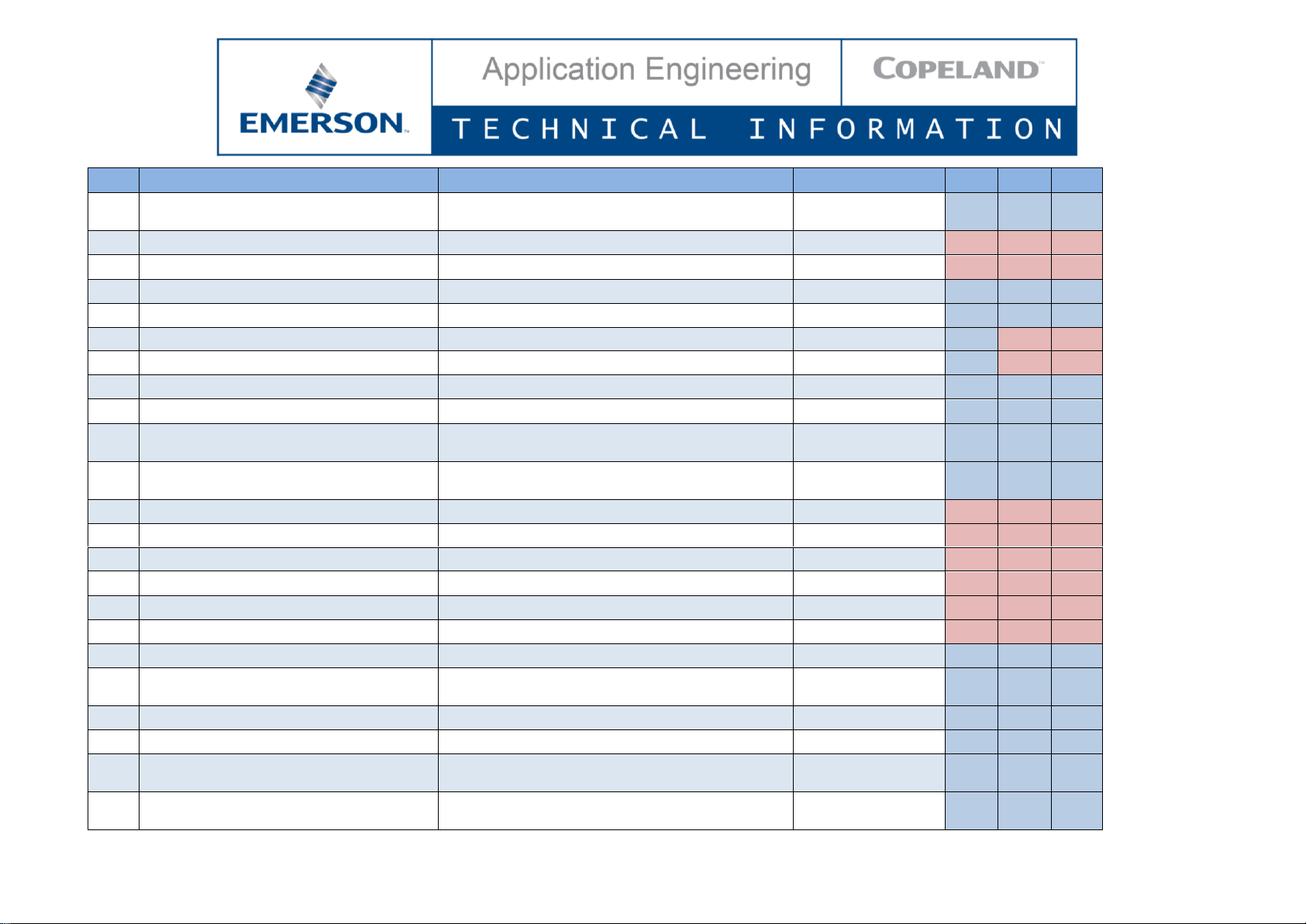
Code
Description
Range
Factory setting
ZXDE
ZXME
ZXLE
A01
Probe P1 configuration
Not used (0-NU)
Suction pressure (0-5V)(1-SUP)
Suction pressure
(0-5V)
L2
L2
L2
A02
Start of scaling for probe 1 (0-5V)
0-5V: -1.5 bar to P1E; -21 PSI to P1E
0
L2
L2
L2
A03
End of scaling for probe 1 (0-5V)
0-5V: P1i to 99.9 bar; P1i to 999 PSI
15
L2
L2
L2
A04
Probe P1 calibration
0-5V: -12.0 to 12.0 bar; -12.0 to12.0 PSI
0
L2
L2
L2
A05
Probe P1 reading error delay (P1C = 0-5V)
0 to 255 min
5
L2
L2
L2
A06
Probe P2 configuration
Not used (0-NU)
Mid-coil temperature (NTC10K)(1-MCT)
Mid-coil pressure (0-5V)(2-MCP)
Mid-coil pressure
(0-5V)
L2
L2
L2
Page 2
CC7.8.17/0220/E 2/22
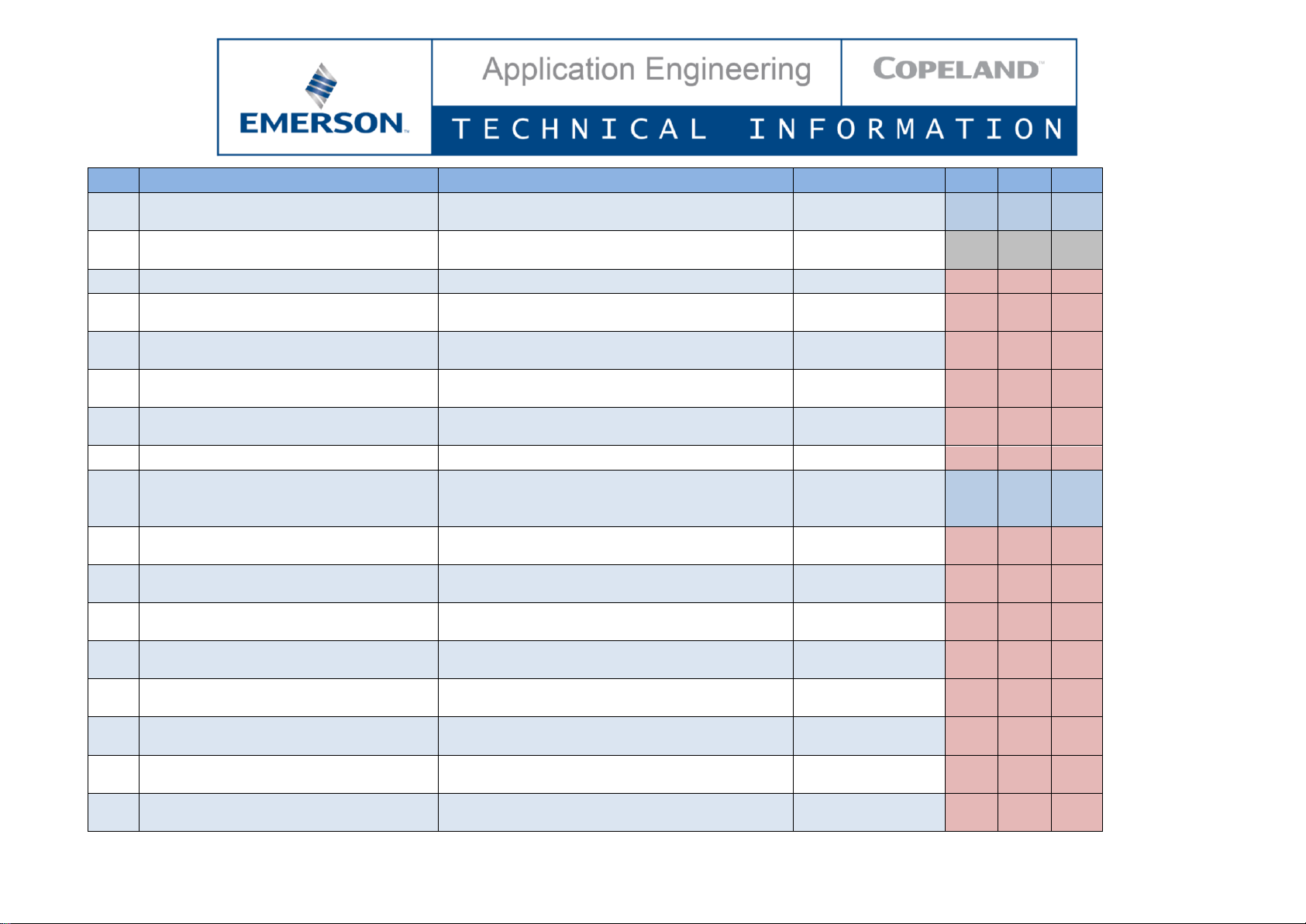
Code
Description
Range
Factory setting
ZXDE
ZXME
ZXLE
A07
Start of scaling for probe 2
0-5V: -1.5 bar to P2E; -21 PSI to P2E
NTC10K: -40°C to P2E
0
L2
L2
L2
A08
End of scaling for probe 2
0-5V: P2i to 99.9 bar; P2i to 999 PSI
NTC10K: P2i to 110°C
35
L2
L2
L2
A09
Probe P2 calibration
0-5V: -12.0 to 12.0 bar; -12.0 to 12.0 PSI
NTC10K: -12°C to 12°C
0
L2
L2
L2
A10
Probe P2 reading error delay (P2C=0-5V)
0 to 255 min
0
L2
L2
L2
A11
Probe P3 configuration
Not used (0-NU)
Discharge line temperature (1-DLT)
Discharge line
temperature
L2
L2
L2
A12
Probe P3 calibration
-12°C to 12°C
0
L2
L2
L2
A13
Probe P4 configuration
Not used (0-NU)
Ambient temperature (NTC10K)(1-AMT)
Thermostat temperature (NTC10K)(2-TMT)
Vapour inlet temperature (NTC10K)(3-UIT)
Vapour outlet temperature (NTC10K)(4-UOT)
Evaporator temperature (NTC10K)(5-EPT)
Liquid temperature (NTC10K)(6-LLT)
Suction line temperature (7-SLT)
Coil temperature (8-COT)
Not used
L2
L2
L2
A14
Probe P4 calibration
-12°C to 12°C
0
L2
L2
L2
A15
Probe P5 configuration
Not used (0-NU)
Ambient temperature (NTC10K)(1-AMT)
Thermostat temperature (NTC10K)(2-TMT)
Vapour inlet temperature (NTC10K)(3-UIT)
Vapour outlet temperature (NTC10K)(4-UOT)
Evaporator temperature (NTC10K)(5-EPT)
Liquid temperature (NTC10K)(6-LLT)
Suction line temperature (7-SLT)
Coil temperature (8-COT)
Not used
L2
L2
L2
A16
Probe P5 calibration
-12°C to 12°C
0
L2
L2
L2
Page 3

CC7.8.17/0220/E 3/22
Code
Description
Range
Factory setting
ZXDE
ZXME
ZXLE
A17
Probe P6 configuration
Not used (0-NU)
Ambient temperature (NTC10K)(1-AMT)
Thermostat temperature (NTC10K)(2-TMT)
Vapour inlet temperature (NTC10K)(3-UIT)
Vapour outlet temperature (NTC10K)(4-UOT)
Evaporator temperature (NTC10K)(5-EPT)
Liquid temperature (NTC10K)(6-LLT)
Suction line temperature (7-SLT)
Coil temperature (8-COT)
Ambient temperature
(NTC10K)
L2
L2
L2
A18
Probe P6 calibration
-12°C to 12°C
0.0
L2
L2
L2
A19
Probe P7 configuration
Not used (0-NU)
Ambient temperature (NTC10K)(1-AMT)
Thermostat temperature (NTC10K)(2-TMT)
Vapour inlet temperature (NTC10K)(3-UIT)
Vapour outlet temperature (NTC10K)(4-UOT)
Evaporator temperature (NTC10K)(5-EPT)
Liquid temperature (NTC10K)(6-LLT)
Suction line temperature (7-SLT)
Coil temperature (8-COT)
Not used
L2
L2
L2
A20
Probe P7 calibration
-12°C to 12°C
0
L2
L2
L2
A21
Delay before activating probe error
0 to 255 sec
0
L2
L2
L2
B01
Measurement unit for pressure
Bar (0-BAR) – PSI (1-PSI) – KPA (2-TPA)
bar
L2
L2
L2
B02
Measurement unit for temperature
°C (0-C)
°C
L2
L2
L2
B03
Remote display visualization
P1 (0-P1) - P2 (1-P2) - P3 (2-P3) P4 (3-P4) - P5 (4-P5) - P6 (5-P6) P7 (6-P7) – Per (7-PER) – Aou (8-AOU)
P1
L2
L2
L2
B04
Filter enabling for probe reading
n (0-NO) - Y (1-YES)
YES
N.V.
N.V.
N.V.
B05
Coefficient for probe reading filter (0 =
max,100 = disable)
0 to 100, mEd (101)
50
N.V.
N.V.
N.V.
C01
Compressor cut-in pressure setpoint
CoU to US
4
N.V.
L1
L1
C02
Compressor cut-out pressure setpoint
LS to Cin
2
L2
L1
L1
C03
Minimum setpoint for suction
pressure/temperature
P1i to US; -50.0°C to US
0.6
L2
L2
L2
Page 4
CC7.8.17/0220/E 4/22
Code
Description
Range
Factory setting
ZXDE
ZXME
ZXLE
C04
Maximum setpoint for suction
pressure/temperature
LS to P1E; LS to 60.0°C
7.2
L2
L2
L2
C05
Compressor regulation probe selection
NU (0-NU)
Suction pressure probe (1-SUP)
Case temperature (2-CST)
Suction pressure switch (3-dIS)
Suction pressure
probe
L2
L2
L2
C06
EXV closing time before compressor off
0 to 999 sec
0
L2
L2
L2
C07
Refrigerant selection for regulation
R404A (0-404) - R507 (1-507)
R134a (2-134) - R22 (3-R22)
R407C (4-07C) - R407A (5-07A)
R407F (6-07F) - R448A (7-48A)
R449A (8-49A)
R404A
L1
L1
L1
C08
Setpoint offset
NU (0-NU)
Small offset (1-SOF)
Medium offset (2-MOF)
Large offset (3-LOF)
LAO (4-FOF)
Not used
L2
L2
L2
C09
Ambient temperature operation setpoint
-40°C to 110°C
-20
L2
L2
L2
C10
Pressure/Temperature operation for ambient
differential
0.0 to 9.9 bar; 0.0 PSI to 99.9 PSI
0.0°C to 25.5°C
1
L2
L2
L2
C11
Ambient temperature recover differential
0.1°C to 25.5°C
5
L2
L2
L2
C12
Ambient temperature threshold for low
ambient operation
-40°C to 110°C
-10
L2
L2
L2
C13
Temperature/Pressure to end low ambient
timer and resume normal operation
-40°C to 110°C
-1.5 to 99.9 bar; -21 to 999 PSI
10
L2
L2
L2
C14
Compressor minimum on time in low ambient
operation
0 to 255 sec
10
L2
L2
L2
C15
Pressure to end low ambient timer and shut
off the compressor
-1.5 to 99.9 bar; -21.0 to 999 PSI
0.5
L2
L2
L2
C16
Digital compressor setpoint
LS to US
3.3
L1
N.V.
N.V.
C17
Proportional band for compressor regulation
0.1 to 9.9 bar; 0.1 to 99.9 PSI; 0.1°C to 25.5°C
2
L1
N.V.
N.V.
C18
Band offset for compressor regulation
0 to 9.9 bar; 0 to 99.9 PSI; 0.0°C to 25.5°C
0
L2
N.V.
N.V.
C19
Integral time
0 to 999 sec
250
L2
L2
N.V.
Page 5
CC7.8.17/0220/E 5/22
Code
Description
Range
Factory setting
ZXDE
ZXME
ZXLE
C20
Start-up time: interval time with digital valve
energized before regulation starts
0.0 to 10.0 sec
10
L2
N.V.
N.V.
C21
Cycle time for digital compressor
10 to 40 sec
20
L1
N.V.
N.V.
C22
Safety value for PI regulator (in case of probe
error)
0 to 100%
50
L2
N.V.
N.V.
C23
Number of active compressor when probe
error
0 (0) – 1 (1) – 2 (2)
0
L2
N.V.
N.V.
C24
Minimum capacity for digital compressor
0 to PMA
20
L1
N.V.
N.V.
C25
Maximum capacity for digital compressor
PMi to 100
100
L1
N.V.
N.V.
C26
Time with DGS at PMA before starting another
load
0 to 255 sec
0
L2
N.V.
N.V.
C27
Time with DGS at PMi before switching off
another load
0 to 255 sec
0
L2
N.V.
N.V.
C28
R404A Enable function
Disable (0-NO) - Enable (1-YES)
Enable
N.V.
N.V.
N.V.
C29
R507 Enable function
Disable (0-NO) - Enable (1-YES)
Enable
N.V.
N.V.
N.V.
C30
R134a Enable function
Disable (0-NO) - Enable (1-YES)
Enable
N.V.
N.V.
N.V.
C31
R22 Enable function
Disable (0-NO) - Enable (1-YES)
Enable
N.V.
N.V.
N.V.
C32
R407C Enable function
Disable (0-NO) - Enable (1-YES)
Enable
N.V.
N.V.
N.V.
C33
R407A Enable function
Disable (0-NO) - Enable (1-YES)
Enable
N.V.
N.V.
N.V.
C34
R407F Enable function
Disable (0-NO) - Enable (1-YES)
Enable
N.V.
N.V.
N.V.
C35
R448A Enable function
Disable (0-NO) - Enable (1-YES)
Enable
N.V.
N.V.
N.V.
C36
R449A Enable function
Disable (0-NO) - Enable (1-YES)
Enable
N.V.
N.V.
N.V.
C37
R410A Enable function
Disable (0-NO) - Enable (1-YES)
Disable
N.V.
N.V.
N.V.
C38
Compressor regulation control signal
Pressure (0-PRS) - temperature (1-TMP)
Pressure
L2
L2
L2
D01
Output delay at start-up
0 to 255 sec
5
L2
L2
L2
D02
Compressor On time with faulty probe
0 to 255 min
0
L2
L2
L2
D03
Compressor Off time with faulty probe
0 to 255 min
0
L2
L2
L2
D04
Minimum time between two starts (same
compressor)
0 to 15 min
4
L2
L2
L2
Page 6
CC7.8.17/0220/E 6/22
Code
Description
Range
Factory setting
ZXDE
ZXME
ZXLE
D05
Delay between compressor switch-off and
start-up (same compressor)
1 to 900 sec
120
L2
L2
L2
D06
Delay between two different loads start-up
[0÷99.5] min, resolution 10 sec
10
N.V.
N.V.
N.V.
D07
Delay between two different loads switch-off
[0÷99.5] min, resolution 10 sec
10
N.V.
N.V.
N.V.
D08
Minimum time a stage stays switched on
[0÷99.5] min, resolution 10 sec
0
L2
L2
L2
D09
Maximum time a stage stays switched on
[0.00÷24.00] hours, resolution 10 min
0
L2
L2
L2
D10
don delay enabled also for the first request
No (0-NO) - Yes (1-YES)
NO
L2
N.V.
N.V.
D11
doF delay enable also for the first switching off
No (0-NO) - Yes (1-YES)
NO
L2
N.V.
N.V.
D12
Low suction pressure alarm delay
0 to 999 sec
0
L2
L2
L2
D13
Low suction pressure error signal enabling
No (0-NO) - Yes (1-YES)
YES
L2
L2
L2
D14
Compressor minimum off time for highpressure switch protection
0 to 15 min
5
L2
L2
L2
D15
Number of high-pressure switch activations
before compressor lockout
0 to 15
7
L2
L2
L2
D16
Bump start enable
No (0-NO) - Yes (1-YES)
NO
N.V.
N.V.
N.V.
D17
Bump start ambient threshold
-40°C to 110°C
0
N.V.
N.V.
N.V.
D18
Compressor stop time for next bump start
0 hour to 23 hours and 50 minutes
1 hour
N.V.
N.V.
N.V.
D19
Compressor on time during bump function
1 to 15 sec
2
N.V.
N.V.
N.V.
D20
Compressor off time during bump function
1 to 15 sec
15
N.V.
N.V.
N.V.
D21
Number of cycles during bump start
1 to 15
3
N.V.
N.V.
N.V.
D22
DLT alarm temperature to stop compressor
-40°C to 180°C
140
L2
L2
L2
D23
DLT alarm recover temperature to turn on
compressor
-40°C to 180°C
90
L2
L2
L2
D24
DLT alarm activation delay
0 to 255 sec
30
L2
L2
L2
D25
Compressor minimum off time for DLT Alarm
0 to 255 min
5
L2
L2
L2
D26
Number of DLT alarm activations before
compressor lockout
0 to 15
10
L2
L2
L2
D27
Time to ignore low DLT sensor error at startup
0 to 255 min
5
L2
L2
L2
Page 7
CC7.8.17/0220/E 7/22
Code
Description
Range
Factory setting
ZXDE
ZXME
ZXLE
D28
Compressor minimum off time for lowpressure switch protection
0 to 15 min
3
L2
L2
L2
D29
Low-pressure alarm value (from serial number
16EZ08855M onwards)
0 to 15 bar
0.5
L1
L1
L1
D30
Cold start enable
Disable (0) - Enable (1)
Disable
N.V.
N.V.
N.V.
D31
DLT temperature threshold to trip during cold
start
-40 to 180°C
60
N.V.
N.V.
N.V.
D32
Suction pressure threshold to trip during cold
start
-1.5 to 99.9 bar
0.5
N.V.
N.V.
N.V.
D33
Allowed number of cycles of DLT temperature
trips during cold start
1 to 15
4
N.V.
N.V.
N.V.
D34
Allowed number of cycles of low-pressure trips
during cold start
1 to 15
4
N.V.
N.V.
N.V.
D35
Compressor stop time during cold start
1 to 999 sec
180
N.V.
N.V.
N.V.
E01
Condenser fan motor modulation type
Not used (0-NU)
Fan cycling (1-CYC)
Modulated fan (2-MOD)
Modulated fan
L2
L2
L2
E02
Low setpoint for condenser fan map 1 (for
R404A, R507)
-40°C to HT1
10
N.V.
N.V.
N.V.
E03
Lower suction pressure point for condenser
fan map 1 (for R404A, R507)
-1.5 bar to HP1; -21 PSI to HP1
3.3
N.V.
N.V.
N.V.
E04
High setpoint for condenser fan map 1 (for
R404)
LT1 to 110°C
30
N.V.
N.V.
N.V.
E05
High suction pressure point for condenser fan
map 1 (for R404A, R507)
LP1 to 99.9 bar; LP1 to 999 PSI
7.2
N.V.
N.V.
N.V.
E06
Low setpoint for condenser fan map 2 (for
R134)
-40°C to HT2
25
N.V.
N.V.
N.V.
E07
Lower suction pressure point for condenser
fan map 2 (for R404)
-1.5 bar to HP2; -21 PSI to HP2
2.5
N.V.
N.V.
N.V.
E08
High setpoint for condenser fan map 2 (for
R134)
LT2 to 110°C
40
N.V.
N.V.
N.V.
E09
High suction pressure point for condenser fan
map 2 (for R404)
LP2 to 99.9 bar; LP2 to 999 PSI
3.9
N.V.
N.V.
N.V.
Page 8

CC7.8.17/0220/E 8/22
Code
Description
Range
Factory setting
ZXDE
ZXME
ZXLE
E10
Low setpoint for condenser fan map 3 (for
R22)
-40°C to HT3
20
N.V.
N.V.
N.V.
E11
Low suction pressure point for condenser fan
map 3 (for R22)
-1.5 bar to HP3; -21PSI to HP3
5.2
N.V.
N.V.
N.V.
E12
High setpoint for condenser fan map 3 (for
R22)
LT3 to 110°C
30
N.V.
N.V.
N.V.
E13
High suction pressure point for condenser fan
map 3 (for R22)
LP3 to 99.9 bar; LP3 to 999 PSI
6.4
N.V.
N.V.
N.V.
E14
Low setpoint for condenser fan map 4 (for
R407C)
-40°C to HT4
10
N.V.
N.V.
N.V.
E15
Lower suction pressure point for condenser
fan map 4 (for R404)
-1.5 bar to HP4; -21 PSI to HP4
1.3
N.V.
N.V.
N.V.
E16
High setpoint for condenser fan map 4 (for
R407C)
LT4 to 110°C
38
N.V.
N.V.
N.V.
E17
High suction pressure point for condenser fan
map 4 (for R404)
LP4 to 99.9 bar; LP4 to 999 PSI
5.4
N.V.
N.V.
N.V.
E18
Low setpoint for condenser fan map 5 (for
R407A)
-40°C to HT5
10
N.V.
N.V.
N.V.
E19
Low suction pressure point for condenser fan
map 5 (for R407A)
-1.5 bar to HP5; -21 PSI to HP5
2.5
N.V.
N.V.
N.V.
E20
High setpoint for condenser fan map 5 (for
R407A)
LT5 to 110°C
27
N.V.
N.V.
N.V.
E21
High suction pressure point for condenser fan
map 5 (for R407A)
LP5 to 99.9 bar; LP5 to 999 PSI
5.3
N.V.
N.V.
N.V.
E22
Low setpoint for condenser fan map 6 (for
R407F)
-40°C to HT6
10
N.V.
N.V.
N.V.
E23
Low suction pressure point for condenser fan
map 6 (for R407F)
-1.5 bar to HP6; -21 PSI to HP6
1.7
N.V.
N.V.
N.V.
E24
High setpoint for condenser fan map 6 (for
R407F)
LT6 to 110°C
38
N.V.
N.V.
N.V.
E25
High suction pressure point for condenser fan
map 6 (for R407F)
LP6 to 99.9 bar; LP6 to 999 PSI
6.3
N.V.
N.V.
N.V.
E26
Low setpoint for condenser fan map 7 (for
R448A)
-40°C to HT7
10
N.V.
N.V.
N.V.
Page 9

CC7.8.17/0220/E 9/22
Code
Description
Range
Factory setting
ZXDE
ZXME
ZXLE
E27
Low suction pressure point for condenser fan
map 7 (for R448A)
-1.5 bar to HP7; -21 PSI to HP7
3.3
N.V.
N.V.
N.V.
E28
High setpoint for condenser fan map 7 (for
R448A)
LT7 to 110°C
30
N.V.
N.V.
N.V.
E29
High suction pressure point for condenser fan
map 7 (for R448A)
LP7 to 99.9 bar; LP7 to 999 PSI
7.2
N.V.
N.V.
N.V.
E30
Low setpoint for condenser fan map 8 (for
R449A)
-40°C to HT8
10
N.V.
N.V.
N.V.
E31
Low suction pressure point for condenser fan
map 8 (for R449A)
-1.5 bar to HP8; -21 PSI to HP8
3.3
N.V.
N.V.
N.V.
E32
High setpoint for condenser fan map 8 (for
R449A)
LT8 to 110°C
30
N.V.
N.V.
N.V.
E33
High suction pressure point for condenser fan
map 8 (for R449A)
LP8 to 99.9 bar; LP8 to 999 PSI
7.2
N.V.
N.V.
N.V.
E34
Low setpoint for condenser fan map 9 (for
R410A)
-40°C to HT9
10
N.V.
N.V.
N.V.
E35
Low suction pressure point for condenser fan
map 9 (for R410A)
-1.5 bar to HP9; -21 PSI to HP9
3.3
N.V.
N.V.
N.V.
E36
High setpoint for condenser fan map 9 (for
R410A)
LT9 to 110°C
30
N.V.
N.V.
N.V.
E37
High suction pressure point for condenser fan
map 9 (for R410A)
LP9 to 99.9 bar; LP9 to 999 PSI
7.2
N.V.
N.V.
N.V.
E38
Fan setpoint modulation enabling
No (0-NO) - Yes (1-YES)
NO
L2
L2
L2
E39
Condenser temperature setpoint when fan
setpoint modulation is disabled
-40°C to 110°C
27
L1
L1
L1
E40
Minimum condenser temperature setpoint
-40°C to 110°C
10
L2
L2
L2
E41
High ambient fan motor override enabled
No (0-NO) - Yes (1-YES)
YES
L2
L2
L2
E42
High ambient fan motor override differential
0.1°C to 25.5°C
5
L2
L2
L2
E43
High DLT fan motor override enabled
No (0-NO) - Yes (1-YES)
YES
L2
L2
L2
E44
High DLT fan motor override differential
-40°C to 180°C
120
L2
L2
L2
E45
Minimum fan motor speed
0 to 100%
40
N.V.
N.V.
N.V.
Page 10

CC7.8.17/0220/E 10/22
Code
Description
Range
Factory setting
ZXDE
ZXME
ZXLE
E46
Regulation band of variable fan
0.1°C to 25.5°C
10
L1
L1
L1
E47
Integration time for fan
0 to 999 sec
500
L2
L2
L2
E48
Fan full speed duration at fan start-up
0 to 255 sec
0
L2
L2
L2
E49
Fan minimum on time
0 to 255 sec
5
L2
L2
L2
E50
Fan minimum off time
0 to 255 sec
10
L2
L2
L2
E51
Fixed condenser fan setpoint
-40°C to 110°C
23
L2
L2
L2
E52
Fan 1 differential
0.1°C to 25.5°C
7
L2
L2
L2
E53
Fan 1 to fan 2 differential
0.1°C to 25.5°C
10
L2
L2
L2
E54
Fan 2 differential
0.1°C to 25.5°C
7
L2
L2
L2
E55
Fan control with ambient sensor - Min ambient
-40°C to E56
0
L2
L2
L2
E56
Fan control with ambient sensor - Max
ambient
E55 to 110°C
20
L2
L2
L2
E57
Fan speed control with ambient sensor
0 to 100%
60
L2
L2
L2
E58
Condenser temperature/pressure threshold for
high alarm
-40°C to 110°C
-1.5 to 99.9 bar; -21 to 999 PSI
27.8
L2
L2
L2
E59
High condenser temperature alarm delay
0 to 255 min
0
L2
L2
L2
E60
High condenser temperature alarm with
compressor off
No (0-NO) - Yes (1-YES)
YES
L2
L2
L2
E61
Condenser temperature/pressure threshold for
alarm recovery
-40°C to E58°C
-1.5 to E58 bar; -21 to E58 PSI
23
L2
L2
L2
F01
Liquid injection setpoint
-40°C to 180°C
130
N.V.
L2
L2
F02
Max DLT temperature before full open
injection
LIS°C to 180°C
137
N.V.
L2
L2
F03
Min DLT temperature before close injection
-40°C to LIS°C
40
N.V.
L2
L2
F04
Mid-coil limp-along for DLT failure - Mid-coil 1
LA2 to 110°C
60
N.V.
L2
N.V.
F05
Mid-coil limp-along for DLT failure - Mid-coil 2
LA3 to LA1
50
N.V.
L2
N.V.
F06
Mid-coil limp-along for DLT failure - Mid-coil 3
LA4 to LA2
40
N.V.
L2
N.V.
F07
Mid-coil limp-along for DLT failure - Mid-coil 4
LA5 to LA3
30
N.V.
L2
N.V.
F08
Mid-coil limp-along for DLT failure - Mid-coil 5
-40°C to LA4
20
N.V.
L2
N.V.
Page 11

CC7.8.17/0220/E 11/22
Code
Description
Range
Factory setting
ZXDE
ZXME
ZXLE
F09
Mid-coil limp-along for DLT failure - Valve
opening 1
LE2 to 100%
100
N.V.
L2
N.V.
F10
Mid-coil limp-along for DLT failure - Valve
opening 2
LE3 to LE1%
80
N.V.
L2
N.V.
F11
Mid-coil limp-along for DLT failure - Valve
opening 3
LE4 to LE2%
60
N.V.
L2
N.V.
F12
Mid-coil limp-along for DLT failure - Valve
opening 4
LE5 to LE3%
35
N.V.
L2
N.V.
F13
Mid-coil limp-along for DLT failure - Valve
opening 5
0 to LE4%
15
N.V.
L2
N.V.
F14
Ambient limp-along for DLT and mid-coil
failure - Temperature 1
MA2 to 110°C
30
N.V.
L2
N.V.
F15
Ambient limp-along for DLT and mid-coil
failure - Temperature 2
-40°C to MA1
20
N.V.
L2
N.V.
F16
Ambient limp-along for DLT and mid-coil
failure - Valve opening 1
ME2 to 100%
80
N.V.
L2
N.V.
F17
Ambient limp-along for DLT and mid-coil
failure - Valve opening 2
0 to ME1%
35
N.V.
L2
N.V.
F18
EVI EXV initial opening – Ambient 1
EA2 to 110°C
35
N.V.
N.V.
L2
F19
EVI EXV initial opening – Ambient 2
EA3 to EA1
30
N.V.
N.V.
L2
F20
EVI EXV initial opening – Ambient 3
EA4 to EA2
25
N.V.
N.V.
L2
F21
EVI EXV initial opening – Ambient 4
-40.0°C to EA3
15
N.V.
N.V.
L2
F22
EVI EXV initial opening – Valve opening 1
EO2 to 100%
60
N.V.
N.V.
L2
F23
EVI EXV initial opening – Valve opening 2
EO3 to EO1%
40
N.V.
N.V.
L2
F24
EVI EXV initial opening – Valve opening 3
EO4 to EO2%
30
N.V.
N.V.
L2
F25
EVI EXV initial opening – Valve opening 4
EO5 to EO3%
20
N.V.
N.V.
L2
F26
EVI EXV initial opening – Valve opening 5
0 to EO4%
10
N.V.
N.V.
L2
F27
EVI EXV initial opening with sensor failure
0 to 100%
40
N.V.
N.V.
L2
F28
Differential between the vapour inlet and the
vapour outlet temperature for R404A
0.0 to 25.5°C
8
N.V.
N.V.
L2
Page 12

CC7.8.17/0220/E 12/22
Code
Description
Range
Factory setting
ZXDE
ZXME
ZXLE
F29
Differential between the vapour inlet and the
vapour outlet temperature for R507
0.0 to 25.5°C
8
N.V.
N.V.
L2
F30
Differential between the vapour inlet and the
vapour outlet temperature for R134a
0.0 to 25.5°C
8
N.V.
N.V.
N.V.
F31
Differential between the vapour inlet and the
vapour outlet temperature for R22
0.0 to 25.5°C
8
N.V.
N.V.
L2
F32
Differential between the vapour inlet and the
vapour outlet temperature for R407C
0.0 to 25.5°C
13
N.V.
N.V.
L2
F33
Differential between the vapour inlet and the
vapour outlet temperature for R407A
0.0 to 25.5°C
13
N.V.
N.V.
L2
F34
Differential between the vapour inlet and the
vapour outlet temperature for R407F
0.0 to 25.5°C
13
N.V.
N.V.
L2
F35
Differential between the vapour inlet and the
vapour outlet temperature for R448A
0.0 to 25.5°C
13
N.V.
N.V.
L2
F36
Differential between the vapour inlet and the
vapour outlet temperature for R449A
0.0 to 25.5°C
13
N.V.
N.V.
L2
F37
Differential between the vapour inlet and the
vapour outlet temperature for R410A
0.0 to 25.5°C
8
N.V.
N.V.
N.V.
F38
Max DLT temperature before changing from
vapour to liquid injection control
-40°C to 180°C
133
N.V.
N.V.
L2
F39
Differential before resuming vapour injection
0.0°C to 25.5°C
10
N.V.
N.V.
L2
F40
Max open EXV warning time
0 to 255 min
2
L2
L2
L2
F41
Delta between setpoint and shortage of
refrigerant error during max open warning
0.0°C to 25.5°C
8
L2
L2
L2
F42
Constant liquid temperature mode enabled for
low ambient EVI injection
No (0-NO) - Yes (1-YES)
NO
N.V.
N.V.
L2
F43
Constant liquid temperature setpoint
-40°C to 110°C
0
N.V.
N.V.
L2
F44
Constant liquid temperature enable
temperature
-40°C to 110°C
-20
N.V.
N.V.
L2
Page 13

CC7.8.17/0220/E 13/22
Code
Description
Range
Factory setting
ZXDE
ZXME
ZXLE
G01
Case temperature probe selection
NU (0-NU)
Mid-coil temperature (1-MCT)
Discharge line temperature (2-DLT)
Ambient temperature (3-AMT)
Thermostat temperature (4-TMT)
Evaporator temperature (5-EPT)
Vapour inlet temperature (6-UIT)
Vapour outlet temperature (7-UOT)
Liquid temperature (8-LLT)
Suction line temperature (9-SLT)
Coil temperature (10-COT)
Not used
L2
L2
L2
G02
Case temperature setpoint
CLS to CUS
2
L2
L2
L2
G03
Case temperature differential
0.1°C to 25.5°C
1
L2
L2
L2
G04
Case temperature low range
-40°C to CUS
-10
L2
L2
L2
G05
Case temperature high range
CLS to 110°C
15
L2
L2
L2
G06
Case probe failure limp-along on time
0 to 255 min
2
L2
L2
L2
G07
Case probe failure limp-along off time
0 to 255 min
1
L2
L2
L2
G08
Compressor and fan status when open door
>> no = normal operation; Fn = Fans off;
cP = Compressor off; Fc = Compr. & fans off
no (0-NO)
Fn (1-FAN)
cP (2-CPR)
Fc (3-F-C)
NO
L2
L2
L2
G09
Regulation with open door
No (0-NO) - Yes (1-YES)
YES
L2
L2
L2
G10
Liquid/vapour injection switch based on SH
activation
No (0-NO) - Yes (1-YES)
YES
L2
L2
L2
G11
Maximum pump-down time
0 to 255 min
3
L2
L2
L2
Page 14

CC7.8.17/0220/E 14/22
Code
Description
Range
Factory setting
ZXDE
ZXME
ZXLE
G12
Defrost probe selection
nu (0-NU)
Mid-coil temperature (1-MCT)
Discharge Line temperature (2-DLT)
Ambient temperature (3-AMT)
Thermostat temperature (4-TMT)
Evaporator temperature (5-EPT)
Vapour inlet temperature (6-UIT)
Vapour outlet temperature (7-UOT)
Liquid temperature (8-LLT)
Suction line temperature (9-SLT)
Coil temperature (10-COT)
Not used
L2
L2
L2
G13
Defrost in probe selection
Not used
L2
L2
L2
G14
Defrost out probe selection
Not used
L2
L2
L2
G15
Threshold percentage to enable intelligent
defrost
0 to 100
40
L2
L2
L2
G16
Duration to calculate the average difference
between the diP and doP
0 to 100 min
5
L2
L2
L2
G17
Defrost type
EL (0-EL)
in (1-IN)
Pulse (2-PLS)
EL
L2
L2
L2
G18
Interval between defrost cycles
0 to 120 h
4
L2
L2
L2
G19
Maximum length for defrost
0 to 255 min
20
L2
L2
L2
G20
Duration of pulse defrost
0 to G19
15
L2
L2
L2
G21
Defrost termination temperature
-40°C to 110°C
10
L2
L2
L2
G22
Defrost delay time
0 to 255 min
0
L2
L2
L2
G23
Defrost interval mode
nu (0-NU)
in (1-IN)
rtC (2-rtC)
Intelligent (3-INT)
Not used
L2
L2
L2
G24
Display during defrost
dEF = Defrost;
Set = Setpoint case temp;
it = Case temp;
rt = Display in standard operation
dEF (0-DEF)
Set (1-SET)
it (2-IT)
rt (3-RT)
dEF
L2
L2
L2
G25
Maximum display delay after defrost
0 to 255 min
0
L2
L2
L2
G26
Drip time
0 to 120 min
1
L2
L2
L2
Page 15

CC7.8.17/0220/E 15/22
Code
Description
Range
Factory setting
ZXDE
ZXME
ZXLE
G27
Defrost at power-on
No (0-NO) - Yes (1-YES)
NO
L2
L2
L2
G28
Workday defrost start 1
00:00 – 23:50; nu
0:00
L2
L2
L2
G29
Workday defrost start 2
00:00 – 23:50; nu
4:00
L2
L2
L2
G30
Workday defrost start 3
00:00 – 23:50; nu
8:00
L2
L2
L2
G31
Workday defrost start 4
00:00 – 23:50; nu
12:00
L2
L2
L2
G32
Workday defrost start 5
00:00 – 23:50; nu
16:00
L2
L2
L2
G33
Workday defrost start 6
00:00 – 23:50; nu
20:00
L2
L2
L2
G34
Holiday defrost start 1
00:00 – 23:50; nu
0:00
L2
L2
L2
G35
Holiday defrost start 2
00:00 – 23:50; nu
4:00
L2
L2
L2
G36
Holiday defrost start 3
00:00 – 23:50; nu
8:00
L2
L2
L2
G37
Holiday defrost start 4
00:00 – 23:50; nu
12:00
L2
L2
L2
G38
Holiday defrost start 5
00:00 – 23:50; nu
16:00
L2
L2
L2
G39
Holiday defrost start 6
00:00 – 23:50; nu
20:00
L2
L2
L2
G40
First weekly holiday
SUN (0-SUN)
MON (1-MON)
TUE (2-TUE)
WED (3-WED)
THU (4-THU)
FRI (5-FRI)
SAT (6-SAT)
nu (7-NU)
SUN
L2
L2
L2
G41
Second weekly holiday
SUN
L2
L2
L2
G42
Fans operating mode
cn = Parallel to compressor, off during defrost;
on = Fans always on, only off during defrost;
cy = Parallel to compressor, on during defrost;
oy = Fans permanently in operation
cn (0-CN)
on (1-ON)
cy (2-CY)
oy (3-OY);
cn
L2
L2
L2
G43
Fans stop temperature
-40°C to 110°C
0
L2
L2
L2
G44
Temperature differential avoiding short cycles
of fans
0 to 59°C
2
L2
L2
L2
G45
Fan On time
0 to 255 min
1
L2
L2
L2
G46
Fan Off time
0 to 255 min
1
L2
L2
L2
Page 16

CC7.8.17/0220/E 16/22
Code
Description
Range
Factory setting
ZXDE
ZXME
ZXLE
G47
Room probe selection for evaporator fan
management
NU (0-NU)
Mid-coil temperature (1-MCT)
Discharge line temperature (2-DLT)
Ambient temperature (3-AMT)
Thermostat temperature (4-TMT)
Not used
L2
L2
L2
G48
Maximum case temperature alarm threshold
G49 to 110°C
10
L2
L2
L2
G49
Minimum case temperature alarm threshold
-40°C to G48
-25
L2
L2
L2
G50
Case temperature alarm restart differential
0.1°C to 25.5°C
3
L2
L2
L2
G51
Case temperature alarm delay
0 to 255 sec
60
L2
L2
L2
G52
Exclusion of temperature alarm at start-up
0 to 255 min
20
L2
L2
L2
G53
Maximum door open time before alarm
0 to 255 min
3
L2
L2
L2
G54
Maximum length for light when door switch is
closed
0 to 255 min
1
L2
L2
L2
G55
Fan delay after defrost
0 to 255 min
1
L2
L2
L2
G56
Use the liquid line solenoid
no; yes
NO
L2
L2
L2
H01
Current sensing 1
no; yes
YES
L2
L2
L2
H02
Current sensing 2
no; yes
YES
L2
L2
L2
H03
Voltage sensing 1
no; yes
NO
L2
L2
L2
H04
Voltage sensing 2
no; yes
NO
L2
L2
L2
H05
Voltage sensing 3
no; yes
NO
L2
L2
L2
H06
Voltage and current protection enabled
no; yes
YES
L2
L2
L2
H07
Maximum continuous current limit
3PE = 0: 0.0 to 70.0 A
3PE = 1: 0.0 to 35.0 A
Unit dependent
L2
L2
L2
H08
Voltage/current sensing trip minimum off time
0 to 255 min
5
L2
L2
L2
H09
Adjustable current limit before trip
0.0 to MCC Ampere
9.5
L2
L2
L2
H10
Ignore current sensing duration at start-up
duration
0 to 255 sec
3
L2
L2
L2
H11
Number of over current trips before lockout
0 to 15
5
L2
L2
L2
H12
Number of loss of phase trips before lockout
0 to 15
5
L2
L2
L2
Page 17

CC7.8.17/0220/E 17/22
Code
Description
Range
Factory setting
ZXDE
ZXME
ZXLE
H13
Minimum voltage to trip compressor
0 to 400V
360
N.V.
N.V.
N.V.
H14
Maximum voltage to trip compressor
0 to 800V
480
N.V.
N.V.
N.V.
H15
Over or under voltage minimum time
0 to 255 sec
60
L2
L2
L2
H16
Compressor minimum off time because of
voltage error
0 to 255 min
3
L2
L2
L2
H17
Number of compressor trips before lockout
because of voltage
0 to 15
5
L2
L2
L2
H18
Adjustable under average voltage percentage
0 to 100%
90
L2
L2
L2
H19
Generate warning or shut down compressor
when phase imbalance
0: Generate warning (0-ARN)
1: Unit off(1-Off)
Unit off
L2
L2
L2
H20
Missing current duration before warning
0 to 255 sec
10
L2
L2
L2
H21
Minimum high side superheat
-40 to 110°C
10
L2
L2
L2
H22
Amount of time allowed in an interval to check
for floodback
0 to H23 min
30
L2
L2
L2
H23
Interval to check for floodback
H22 to 120 min
45
N.V.
N.V.
L2
H24
Duration of checking anti-floodback alarm
reset condition
1 to 255 min
20
N.V.
N.V.
L2
H25
Three-phase enable
no; yes
YES
L2
L2
L2
I01
Ambient temperature threshold to off
crankcase heater
-40°C to 180°C
10
L2
L2
L2
I02
Compressor minimum off time before turning
the crankcase heater on
0 to 255 min
5
L2
L2
L2
L01
Steps for initial regulation
SH2 to SH1 steps
15
L2
N.V.
L2
L02
Superheating setpoint
0.0°C to 25.5°C
5
L2
N.V.
L2
L03
Threshold of low superheating
0.0 to SH18°C
1
L2
N.V.
L2
L04
Threshold of high superheating
SH17 to 80.0°C
15
L2
N.V.
L2
L05
Extra % of valve close in case of low
superheating
0 to 100%
0
L2
N.V.
N.V.
L06
Delay high superheating
0 to 255 sec
30
L2
N.V.
N.V.
L07
Delay low superheating
0 to 255 sec
30
L2
N.V.
N.V.
Page 18

CC7.8.17/0220/E 18/22
Code
Description
Range
Factory setting
ZXDE
ZXME
ZXLE
L08
Threshold of MOP
SH23 to 60.0°C
35
L2
N.V.
N.V.
L09
Threshold of LOP
-50°C to SH22°C
-20
L2
N.V.
N.V.
L10
Activation delay MOP
0 to 255 sec
1
L2
N.V.
N.V.
L11
Activation delay LOP
0 to 255 sec
1
L2
N.V.
N.V.
L12
Steps close/open in case of MOP/LOP
0 to SH1 steps
20
L2
N.V.
N.V.
M01
Max step valve
SH2 to 800 steps
250
L2
L2
L2
M02
Min step valve
0 to SH1 steps
0
L2
L2
L2
M03
Extra steps of valve close
0 to 100 steps
20
L2
L2
L2
M04
Relax steps
0 to 100 steps
0
L2
L2
L2
M05
Step rate
10 to 100 steps
35
L2
L2
L2
M06
Regulation of the valve 0: automatic,
1: manual
Automatic (0-AUT)
Manual (1-MAN)
Automatic
L2
L2
L2
M07
Steps if manual regulation
SH2 to SH1 steps
15
L2
L2
L2
M08
Proportional band (if 0 the regulation is auto
adaptive)
0 to 50°C
0
L2
L2
L2
M09
Integral time
0 to 255 sec
20
L2
L2
L2
M10
Derivative
0 to 255 sec
0
L2
L2
L2
M11
Dead band
0 to10°C
1
L2
L2
L2
M12
Min % of the valve
0 to SH15
0
L2
L2
L2
M13
Max % of the valve
SH14 to 100
100
L2
L2
L2
M14
Filter on the pressure
1 to 255 sec
1
L2
L2
L2
M15
Interval of updating valve
1 to 255 sec
20
L2
L2
L2
M16
Filter on the temperature [1-100] sec
1 to 255 sec
1
L2
L2
L2
M17
Activation delay probe error
0 to 255 sec
1
L2
L2
L2
M18
% valve in case of probe error
0 to 100%
50
L2
L2
L2
M19
Time at initial steps at the start time
0 to 255 sec
30
L2
L2
L2
N01
Current minute
0 to 59
L1
L1
L1
Page 19

CC7.8.17/0220/E 19/22
Code
Description
Range
Factory setting
ZXDE
ZXME
ZXLE
N02
Current hour
0 to 23
L1
L1
L1
N03
Day of month
1 to 31
L1
L1
L1
N04
Month
1 to 12
L1
L1
L1
N05
Year
0 to 99
L1
L1
L1
P01
Compressor setpoint hysteresis in energy
saving mode
0.0 to 9.9 bar; 0. to 99.9 PSI;
0.0°C to 25.5°C
0
L2
L2
L2
P02
Condenser setpoint hysteresis in energy
saving mode
0.0°C to 25.5°C
0
L2
L2
L2
R01
Digital input 1 function
Not used (0-NU)
Suction pressure switch (1-SUS)
Thermostat input (2-DEF)
High-pressure input (3-HP)
Low-pressure input (4-LP)
Door switch (5-DOR)
Energy saving enable (6-ES)
On/Off (7-ONF)
Not used
L2
L2
L2
R02
Digital input 1 polarity
oP (0) - CL (1)
CL
L2
L2
L2
R03
Activation delay for digital input 1
0 to 255 min
0
L2
L2
L2
R04
Digital input 2 function
Not used (0-NU)
Suction pressure switch (1-SUS)
Thermostat input (2-DEF)
High-pressure input (3-HP)
Low-pressure input (4-LP)
Door switch (5-DOR)
Energy saving enable (6-ES)
On/Off (7-ONF)
High-pressure input
N.V.
N.V.
N.V.
R05
Digital input 2 polarity
oP (0) - CL (1)
oP
N.V.
N.V.
N.V.
R06
Activation delay for digital input 2
0 to 255 min
0
N.V.
N.V.
N.V.
Page 20

CC7.8.17/0220/E 20/22
Code
Description
Range
Factory setting
ZXDE
ZXME
ZXLE
R07
Digital input 3 function
Not used (0-NU)
Suction pressure switch (1-SUS)
Thermostat input (2-DEF)
High-pressure input (3-HP)
Low-pressure input (4-LP)
Door switch (5-DOR)
Energy saving enable (6-ES)
On/Off (7-ONF)
Not used
L2
L2
L2
R08
Digital input 3 polarity
oP (0) - CL (1)
CL
L2
L2
L2
R09
Activation delay for digital input 3
0 to 255 min
0
L2
L2
L2
S01
Alarm contact activation in a warning, alarm,
lockout
Warning (0-ARN) - Alarm (1-ALM) Lockout (2-LOC)
Alarm
L2
L2
L2
S02
Alarm relay deactivation
No (0-NO) - Yes (1-YES)
YES
L2
L2
L2
S03
Buzzer enabled
No (0-NO) - Yes (1-YES)
NO
L2
L2
L2
S04
Relay output 1 configuration
Not used (0-NU)
DGS compressor (1-DGS)
On-Off compressor (2-CPR)
Condenser fan 1 (3-CF1)
Condenser fan 2 (4-CF2)
Evaporator fan (5-EPF)
Defrost (6-DEF)
Liquid line solenoid (7-LLS)
Crankcase heater (8-HTR)
Alarm (9-ALM)
Light (10-LIG)
Crankcase heater
L2
L2
L2
S05
Relay output 2 configuration
Not used
L2
L2
L2
S06
Relay output 3 configuration
Digital Scroll
compressor
L2
L2
L2
S07
Relay output 4 configuration
Not used
L2
L2
L2
S08
Relay output 5 configuration
Alarm
L2
L2
L2
S09
Triac output 1 configuration
Not used (0-NU)
Digital solenoid (1-DGT)
Wave-form chopper for fan speed (2-PCF)
PWM fan speed (3-PEF)
0-10V (4-UEF)
Digital solenoid
L2
L2
L2
S10
Triac output 2 configuration
Not used (0-NU)
Digital solenoid (1-DGT)
Wave-form chopper for fan speed (2-PCF)
Wave-form chopper
for fan speed
L2
L2
L2
Page 21

CC7.8.17/0220/E 21/22
Code
Description
Range
Factory setting
ZXDE
ZXME
ZXLE
S11
EXV Configuration
Not used (0-NU)
Liquid injection EXV (1-LIN)
EVI EXV (2-UIN)
System EXV (3-SHT)
Not used
L2
L2
L2
S12
Output 1 polarity
oP (0) - CL (1)
CL
N.V.
N.V.
N.V.
S13
Output 2 polarity
oP (0) - CL (1)
CL
L2
L2
L2
T01
Serial address
1 to 247
1
L2
L2
L2
T02
Reset key configuration
nP (0-NU) - rSt (1-RST)
rSt
L2
L2
L2
T03
Period time of menu exit without pressing any
key
10 to 120 sec
30
N.V.
N.V.
N.V.
T04
Time for showing firmware version at start-up
0 to 60 sec
3
N.V.
N.V.
N.V.
T05
Time for showing program name at start-up
0 to 60 sec
3
N.V.
N.V.
N.V.
T06
P1 visualization
0 to 999
L2
L2
L2
T07
P2 visualization
0 to 999
L2
L2
L2
T08
P3 visualization
0 to 999
L2
L2
L2
T09
P4 visualization
0 to 999
L2
L2
L2
T10
P5 visualization
0 to 999
L2
L2
L2
T11
P6 visualization
0 to 999
L2
L2
L2
T12
P7 visualization
0 to 999
L2
L2
L2
T13
Firmware release: day
[1÷31] L2
L2
L2
T14
Firmware release: month
[1÷12] L2
L2
L2
T15
Firmware release: year
[0÷999]
L2
L2
L2
T16
Firmware release code
[0÷999]
L2
L2
L2
T17
EEPROM map identification
[0÷999]
6
L2
L2
L2
T18
Access PR2 level
[0÷999]
L1
L1
L1
Page 22

CC7.8.17/0220/E 22/22
DISCLAIMER
1. The contents of this publication are presented for informational purposes only and are not to be construed as warranties or guarantees, express or implied,
regarding the products or services described herein or their use or applicability.
2. Emerson Climate Technologies GmbH and/or its affiliates (collectively "Emerson"), as applicable, reserve the right to modify the design or specifications
of such products at any time without notice.
3. Emerson does not assume responsibility for the selection, use or maintenance of any product. Responsibility for proper selection, use and maintenance
of any Emerson product remains solely with the purchaser or end user.
4. Emerson does not assume responsibility for possible typographic errors contained in this publication.
 Loading...