

Page 1
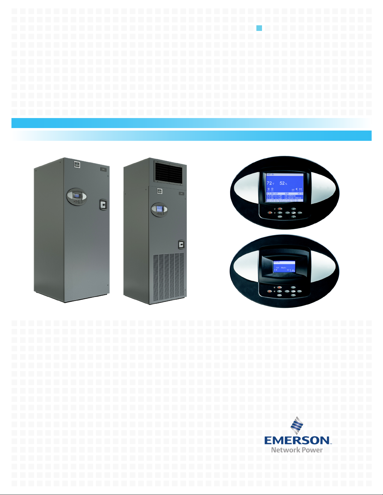
Liebert Challenger™ 3000 with iCOM
Installation Manual - 3 & 5 Tons, 50 & 60Hz
Precision Cooling
For Business-Critical Continuity™
Page 2

Page 3

TABLE OF CONTENTS
IMPORTANT SAFETY INSTRUCTIONS . . . . . . . . . . . . . . . . . . . . . . . . . . . . . . . . . . . . . . . . . . . . . . . . 1
1.0 INTRODUCTION . . . . . . . . . . . . . . . . . . . . . . . . . . . . . . . . . . . . . . . . . . . . . . . . . . . . . . . . . .3
1.1 System Descriptions . . . . . . . . . . . . . . . . . . . . . . . . . . . . . . . . . . . . . . . . . . . . . . . . . . . . . . . . . . 3
1.1.1 Self-Contained Systems . . . . . . . . . . . . . . . . . . . . . . . . . . . . . . . . . . . . . . . . . . . . . . . . . . . . . . . . 3
1.1.2 Chilled Water Models . . . . . . . . . . . . . . . . . . . . . . . . . . . . . . . . . . . . . . . . . . . . . . . . . . . . . . . . . . 3
1.1.3 Split Systems . . . . . . . . . . . . . . . . . . . . . . . . . . . . . . . . . . . . . . . . . . . . . . . . . . . . . . . . . . . . . . . . 4
2.0 INSTALLATION (APPLICABLE TO ALL MODELS). . . . . . . . . . . . . . . . . . . . . . . . . . . . . . . . . . .5
2.1 Room Preparation. . . . . . . . . . . . . . . . . . . . . . . . . . . . . . . . . . . . . . . . . . . . . . . . . . . . . . . . . . . . 5
2.2 Equipment Inspection . . . . . . . . . . . . . . . . . . . . . . . . . . . . . . . . . . . . . . . . . . . . . . . . . . . . . . . . 5
2.3 Location Considerations. . . . . . . . . . . . . . . . . . . . . . . . . . . . . . . . . . . . . . . . . . . . . . . . . . . . . . . 5
2.4 Equipment Handling . . . . . . . . . . . . . . . . . . . . . . . . . . . . . . . . . . . . . . . . . . . . . . . . . . . . . . . . . 5
2.4.1 Handling With Skid . . . . . . . . . . . . . . . . . . . . . . . . . . . . . . . . . . . . . . . . . . . . . . . . . . . . . . . . . . . 6
2.4.2 Removal of Skid . . . . . . . . . . . . . . . . . . . . . . . . . . . . . . . . . . . . . . . . . . . . . . . . . . . . . . . . . . . . . . 6
2.5 Piping Considerations . . . . . . . . . . . . . . . . . . . . . . . . . . . . . . . . . . . . . . . . . . . . . . . . . . . . . . . . 9
2.5.1 Drain Line . . . . . . . . . . . . . . . . . . . . . . . . . . . . . . . . . . . . . . . . . . . . . . . . . . . . . . . . . . . . . . . . . . . 9
2.5.2 Humidifier Supply Water—Optional Infrared . . . . . . . . . . . . . . . . . . . . . . . . . . . . . . . . . . . . . 18
2.6 Facility Fluid and Piping Maintenance. . . . . . . . . . . . . . . . . . . . . . . . . . . . . . . . . . . . . . . . . . 18
2.7 Electrical Connections . . . . . . . . . . . . . . . . . . . . . . . . . . . . . . . . . . . . . . . . . . . . . . . . . . . . . . . 18
2.8 Balancing the Air Distribution . . . . . . . . . . . . . . . . . . . . . . . . . . . . . . . . . . . . . . . . . . . . . . . . 21
2.8.1 Under-Floor Discharge Systems . . . . . . . . . . . . . . . . . . . . . . . . . . . . . . . . . . . . . . . . . . . . . . . . 21
2.8.2 Ducted Applications . . . . . . . . . . . . . . . . . . . . . . . . . . . . . . . . . . . . . . . . . . . . . . . . . . . . . . . . . . 21
2.8.3 Plenum Installation . . . . . . . . . . . . . . . . . . . . . . . . . . . . . . . . . . . . . . . . . . . . . . . . . . . . . . . . . . 21
2.9 Checklist for Completed Installation . . . . . . . . . . . . . . . . . . . . . . . . . . . . . . . . . . . . . . . . . . . 22
3.0 AIR-COOLED MODELS—SELF-CONTAINED COMPRESSOR . . . . . . . . . . . . . . . . . . . . . . . . .23
3.1 Condenser Location . . . . . . . . . . . . . . . . . . . . . . . . . . . . . . . . . . . . . . . . . . . . . . . . . . . . . . . . . 23
3.2 Electrical Connections . . . . . . . . . . . . . . . . . . . . . . . . . . . . . . . . . . . . . . . . . . . . . . . . . . . . . . . 23
3.2.1 Line Voltage . . . . . . . . . . . . . . . . . . . . . . . . . . . . . . . . . . . . . . . . . . . . . . . . . . . . . . . . . . . . . . . . 23
3.2.2 Low Voltage . . . . . . . . . . . . . . . . . . . . . . . . . . . . . . . . . . . . . . . . . . . . . . . . . . . . . . . . . . . . . . . . 23
3.2.3 Liebert Lee-Temp/Flood Back Head Pressure Control Condensers . . . . . . . . . . . . . . . . . . . . 23
3.3 Refrigerant Piping . . . . . . . . . . . . . . . . . . . . . . . . . . . . . . . . . . . . . . . . . . . . . . . . . . . . . . . . . . 25
3.4 Fan Speed Control Systems . . . . . . . . . . . . . . . . . . . . . . . . . . . . . . . . . . . . . . . . . . . . . . . . . . . 26
3.5 Air-Cooled Condenser with Liebert Lee-Temp “Flooded Condenser” Head Pressure
Control System . . . . . . . . . . . . . . . . . . . . . . . . . . . . . . . . . . . . . . . . . . . . . . . . . . . . . . . . . . . . 31
4.0 WATER-COOLED MODELS—SELF-CONTAINED COMPRESSOR . . . . . . . . . . . . . . . . . . . . . .35
4.1 Piping Considerations . . . . . . . . . . . . . . . . . . . . . . . . . . . . . . . . . . . . . . . . . . . . . . . . . . . . . . . 35
4.2 Condenser . . . . . . . . . . . . . . . . . . . . . . . . . . . . . . . . . . . . . . . . . . . . . . . . . . . . . . . . . . . . . . . . . 35
4.3 Water Regulating Valve. . . . . . . . . . . . . . . . . . . . . . . . . . . . . . . . . . . . . . . . . . . . . . . . . . . . . . 38
4.3.1 Standard Valve - 150psig (1034 kPa) System for 3 & 5-Ton Units (Johnson Controls
Valve) High Pressure Valve - 350psig (2413kPa) System for 5-Ton Units (Johnson
Controls Valve) . . . . . . . . . . . . . . . . . . . . . . . . . . . . . . . . . . . . . . . . . . . . . . . . . . . . . . . . . . . . . . 38
4.3.2 High Pressure Valve - 350 psig (2413 kPa) System for 3-Ton Units (Metrex Valve) . . . . . . . 38
4.4 Motorized Ball Valve—Digital Scroll Compressors . . . . . . . . . . . . . . . . . . . . . . . . . . . . . . . . 39
4.4.1 Control. . . . . . . . . . . . . . . . . . . . . . . . . . . . . . . . . . . . . . . . . . . . . . . . . . . . . . . . . . . . . . . . . . . . . 39
4.4.2 Adjustment . . . . . . . . . . . . . . . . . . . . . . . . . . . . . . . . . . . . . . . . . . . . . . . . . . . . . . . . . . . . . . . . . 40
4.4.3 Startup . . . . . . . . . . . . . . . . . . . . . . . . . . . . . . . . . . . . . . . . . . . . . . . . . . . . . . . . . . . . . . . . . . . . 40
4.4.4 Location. . . . . . . . . . . . . . . . . . . . . . . . . . . . . . . . . . . . . . . . . . . . . . . . . . . . . . . . . . . . . . . . . . . . 40
4.4.5 Manual Control. . . . . . . . . . . . . . . . . . . . . . . . . . . . . . . . . . . . . . . . . . . . . . . . . . . . . . . . . . . . . . 40
i
Page 4

5.0 GLYCOL/GLYCOOL-COOLED MODELS—SELF-CONTAINED COMPRESSOR . . . . . . . . . . . .41
5.1 Drycooler Location . . . . . . . . . . . . . . . . . . . . . . . . . . . . . . . . . . . . . . . . . . . . . . . . . . . . . . . . . . 41
5.2 Drycooler Installation . . . . . . . . . . . . . . . . . . . . . . . . . . . . . . . . . . . . . . . . . . . . . . . . . . . . . . . 41
5.3 Electrical Connections . . . . . . . . . . . . . . . . . . . . . . . . . . . . . . . . . . . . . . . . . . . . . . . . . . . . . . . 41
5.3.1 Line Voltage . . . . . . . . . . . . . . . . . . . . . . . . . . . . . . . . . . . . . . . . . . . . . . . . . . . . . . . . . . . . . . . . 41
5.3.2 Low Voltage . . . . . . . . . . . . . . . . . . . . . . . . . . . . . . . . . . . . . . . . . . . . . . . . . . . . . . . . . . . . . . . . 41
5.3.3 Pump and Drycooler . . . . . . . . . . . . . . . . . . . . . . . . . . . . . . . . . . . . . . . . . . . . . . . . . . . . . . . . . . 41
5.4 Glycol Piping. . . . . . . . . . . . . . . . . . . . . . . . . . . . . . . . . . . . . . . . . . . . . . . . . . . . . . . . . . . . . . . 42
5.4.1 Expansion Tanks, Fluid Relief Valves and Other Devices. . . . . . . . . . . . . . . . . . . . . . . . . . . . 44
5.5 Filling Instructions. . . . . . . . . . . . . . . . . . . . . . . . . . . . . . . . . . . . . . . . . . . . . . . . . . . . . . . . . . 44
5.5.1 Preparing the System for Filling . . . . . . . . . . . . . . . . . . . . . . . . . . . . . . . . . . . . . . . . . . . . . . . . 44
5.5.2 Glycol Solutions . . . . . . . . . . . . . . . . . . . . . . . . . . . . . . . . . . . . . . . . . . . . . . . . . . . . . . . . . . . . . 45
5.5.3 Filling the System . . . . . . . . . . . . . . . . . . . . . . . . . . . . . . . . . . . . . . . . . . . . . . . . . . . . . . . . . . . 46
5.5.4 Motor Ball Valve—Digital Scroll Compressors . . . . . . . . . . . . . . . . . . . . . . . . . . . . . . . . . . . . . 53
5.6 Condenser . . . . . . . . . . . . . . . . . . . . . . . . . . . . . . . . . . . . . . . . . . . . . . . . . . . . . . . . . . . . . . . . . 53
5.7 Glycol Regulating Valve. . . . . . . . . . . . . . . . . . . . . . . . . . . . . . . . . . . . . . . . . . . . . . . . . . . . . . 53
5.7.1 Standard Valve - 150psig (1034 kPa) System for 3 & 5-Ton Units (Johnson Controls
Valve) High Pressure Valve - 350psig (2413kPa) System for 5-Ton Units (Johnson
Controls Valve) . . . . . . . . . . . . . . . . . . . . . . . . . . . . . . . . . . . . . . . . . . . . . . . . . . . . . . . . . . . . . . 53
5.7.2 High Pressure Valve - 350 psig (2413 kPa) System for 3-Ton Units (Metrex Valve) . . . . . . . 53
5.7.3 Testing Valve Function . . . . . . . . . . . . . . . . . . . . . . . . . . . . . . . . . . . . . . . . . . . . . . . . . . . . . . . 53
6.0 CHILLED WATER MODELS. . . . . . . . . . . . . . . . . . . . . . . . . . . . . . . . . . . . . . . . . . . . . . . . .54
6.1 Piping Considerations . . . . . . . . . . . . . . . . . . . . . . . . . . . . . . . . . . . . . . . . . . . . . . . . . . . . . . . 54
7.0 SPLIT SYSTEM MODELS . . . . . . . . . . . . . . . . . . . . . . . . . . . . . . . . . . . . . . . . . . . . . . . . . . 56
7.1 Location Considerations. . . . . . . . . . . . . . . . . . . . . . . . . . . . . . . . . . . . . . . . . . . . . . . . . . . . . . 56
7.1.1 Air-Cooled Condensing Units. . . . . . . . . . . . . . . . . . . . . . . . . . . . . . . . . . . . . . . . . . . . . . . . . . . 56
7.1.2 Water/Glycol-Cooled Condensing Units . . . . . . . . . . . . . . . . . . . . . . . . . . . . . . . . . . . . . . . . . . 56
7.2 Electrical Connections . . . . . . . . . . . . . . . . . . . . . . . . . . . . . . . . . . . . . . . . . . . . . . . . . . . . . . . 56
7.2.1 Line Voltage . . . . . . . . . . . . . . . . . . . . . . . . . . . . . . . . . . . . . . . . . . . . . . . . . . . . . . . . . . . . . . . . 56
7.2.2 Low Voltage . . . . . . . . . . . . . . . . . . . . . . . . . . . . . . . . . . . . . . . . . . . . . . . . . . . . . . . . . . . . . . . . 57
7.3 Piping Considerations . . . . . . . . . . . . . . . . . . . . . . . . . . . . . . . . . . . . . . . . . . . . . . . . . . . . . . . 57
7.3.1 Refrigerant Loop. . . . . . . . . . . . . . . . . . . . . . . . . . . . . . . . . . . . . . . . . . . . . . . . . . . . . . . . . . . . . 57
7.3.2 Quick Connect Fittings . . . . . . . . . . . . . . . . . . . . . . . . . . . . . . . . . . . . . . . . . . . . . . . . . . . . . . . 59
7.4 Outdoor Air-Cooled Condensing Units . . . . . . . . . . . . . . . . . . . . . . . . . . . . . . . . . . . . . . . . . . 60
7.5 Centrifugal Air-Cooled Condensing Units . . . . . . . . . . . . . . . . . . . . . . . . . . . . . . . . . . . . . . . 65
7.5.1 Installing the Indoor Condensing Unit . . . . . . . . . . . . . . . . . . . . . . . . . . . . . . . . . . . . . . . . . . . 65
7.5.2 Ducting . . . . . . . . . . . . . . . . . . . . . . . . . . . . . . . . . . . . . . . . . . . . . . . . . . . . . . . . . . . . . . . . . . . . 66
7.6 Water and Glycol-Cooled Condensing Units. . . . . . . . . . . . . . . . . . . . . . . . . . . . . . . . . . . . . . 72
7.6.1 Piping Considerations . . . . . . . . . . . . . . . . . . . . . . . . . . . . . . . . . . . . . . . . . . . . . . . . . . . . . . . . 72
7.6.2 Condenser Water Requirements . . . . . . . . . . . . . . . . . . . . . . . . . . . . . . . . . . . . . . . . . . . . . . . . 72
7.6.3 Regulating Valve . . . . . . . . . . . . . . . . . . . . . . . . . . . . . . . . . . . . . . . . . . . . . . . . . . . . . . . . . . . . 72
7.6.4 Glycol Systems . . . . . . . . . . . . . . . . . . . . . . . . . . . . . . . . . . . . . . . . . . . . . . . . . . . . . . . . . . . . . . 73
8.0 R407C REFRIGERANT . . . . . . . . . . . . . . . . . . . . . . . . . . . . . . . . . . . . . . . . . . . . . . . . . . .77
8.1 Calculating Subcooling. . . . . . . . . . . . . . . . . . . . . . . . . . . . . . . . . . . . . . . . . . . . . . . . . . . . . . . 78
ii
Page 5

FIGURES
Figure 1 Removing Challenger from skid . . . . . . . . . . . . . . . . . . . . . . . . . . . . . . . . . . . . . . . . . . . . . . . . . . . . . 6
Figure 2 Upflow (BU) cabinet dimensions . . . . . . . . . . . . . . . . . . . . . . . . . . . . . . . . . . . . . . . . . . . . . . . . . . . . 7
Figure 3 Downflow (BF) cabinet dimensions . . . . . . . . . . . . . . . . . . . . . . . . . . . . . . . . . . . . . . . . . . . . . . . . . . 8
Figure 4 Piping connections for air-cooled units - Downflow models . . . . . . . . . . . . . . . . . . . . . . . . . . . . . . 10
Figure 5 Piping connections for air-cooled units - Upflow models . . . . . . . . . . . . . . . . . . . . . . . . . . . . . . . . 11
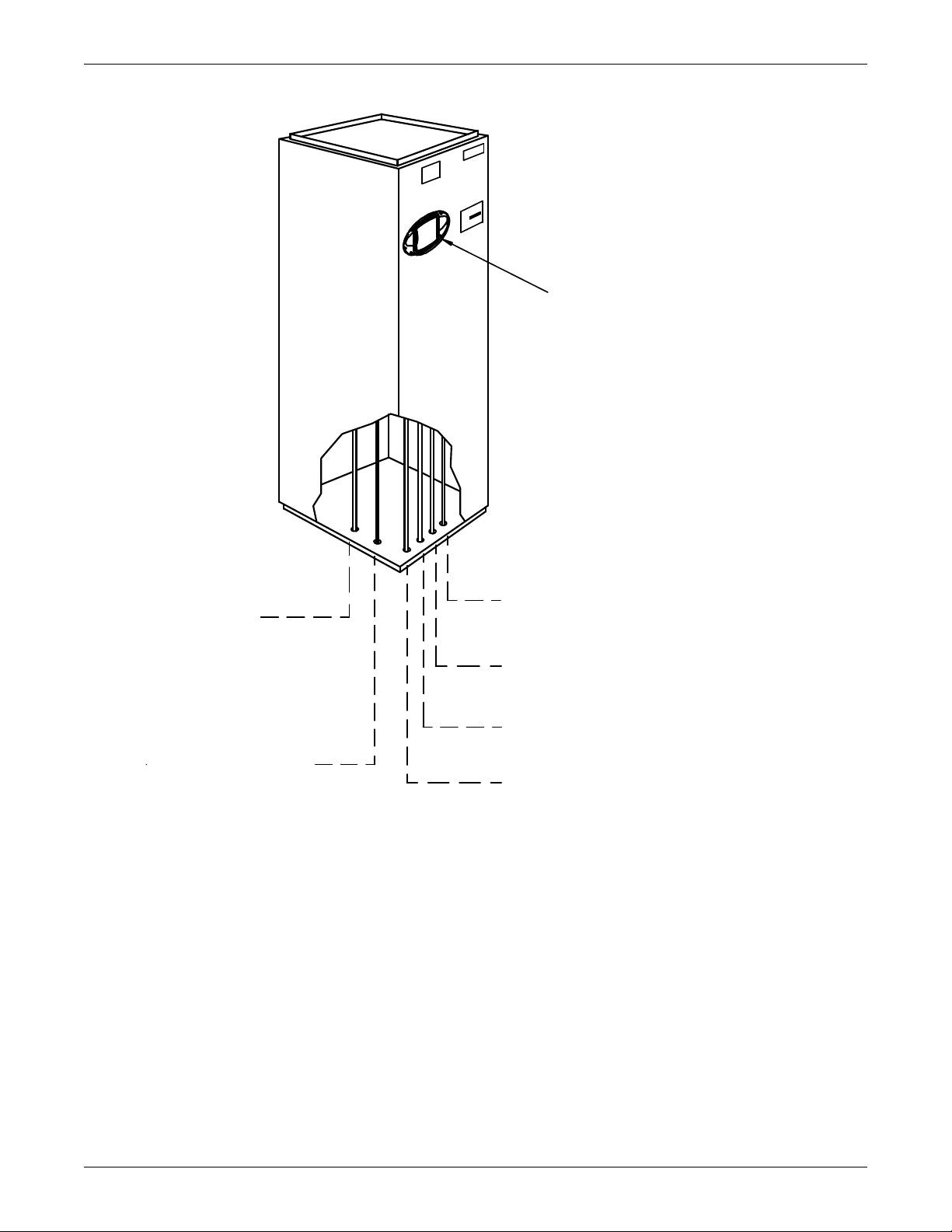
Figure 6 Piping connections for split system fan coil units - Downflow models . . . . . . . . . . . . . . . . . . . . . 12
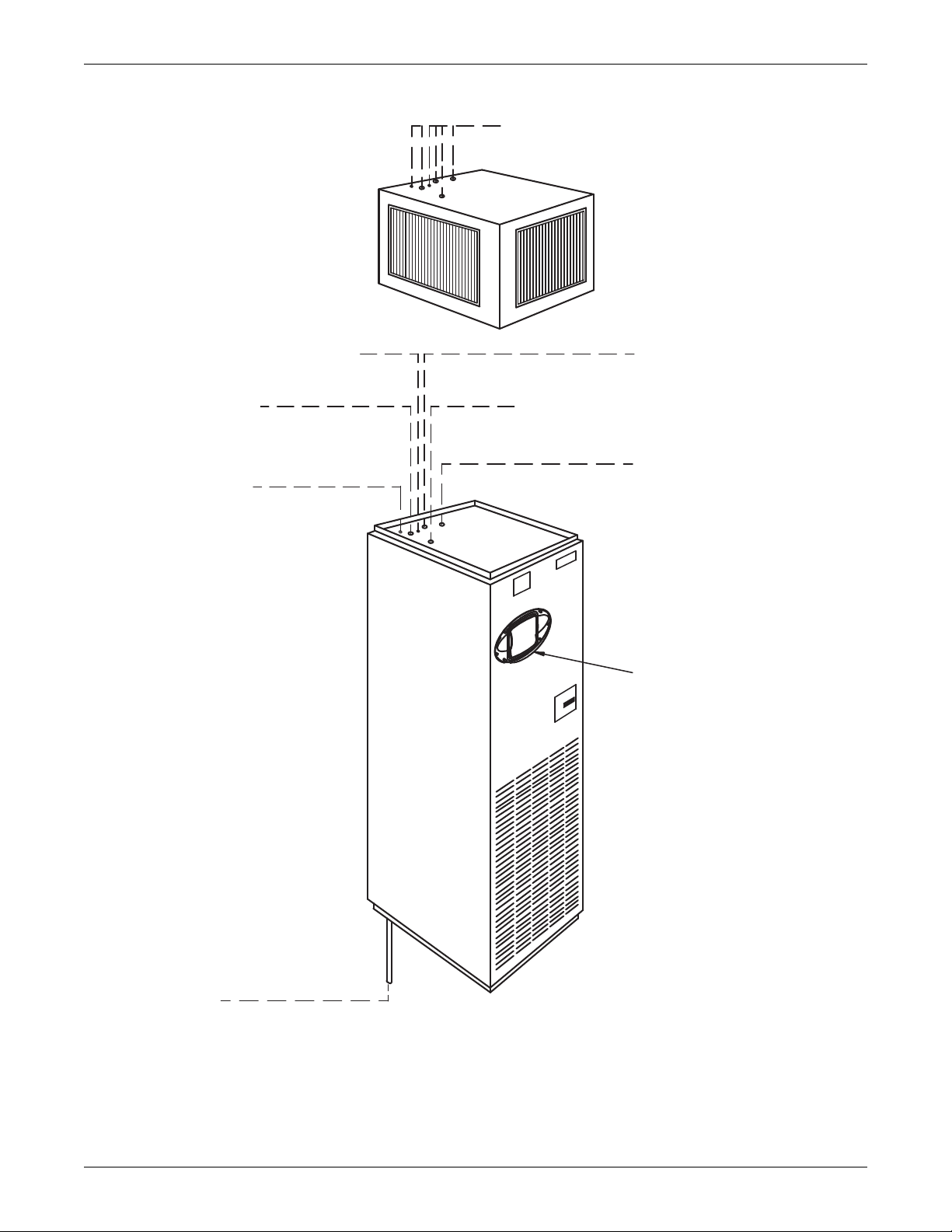
Figure 7 Piping connections for split system fan coil units - Upflow models . . . . . . . . . . . . . . . . . . . . . . . 13
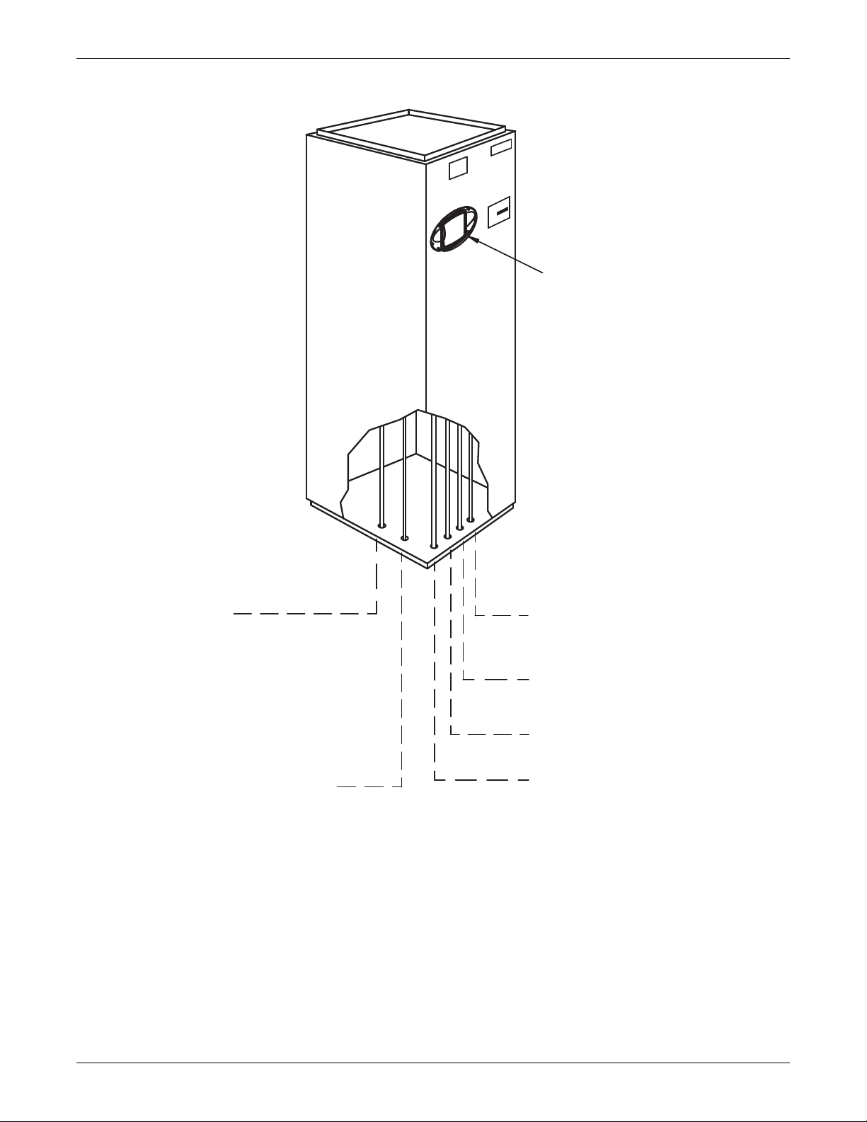
Figure 8 Piping connections for water/glycol and GLYCOOL units - Downflow models . . . . . . . . . . . . . . 14
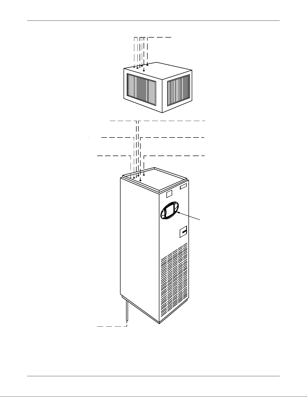
Figure 9 Piping connections for water/glycol and GLYCOOL units - Upflow models . . . . . . . . . . . . . . . . . 15
Figure 10 Piping connections for chilled water self-contained units - Downflow models . . . . . . . . . . . . . . . 16
Figure 11 Piping connections for chilled water self-contained units - Upflow models . . . . . . . . . . . . . . . . . 17
Figure 12 Electrical connections . . . . . . . . . . . . . . . . . . . . . . . . . . . . . . . . . . . . . . . . . . . . . . . . . . . . . . . . . . . . 19
Figure 13 Electrical field connections for Liebert iCOM . . . . . . . . . . . . . . . . . . . . . . . . . . . . . . . . . . . . . . . . . 20
Figure 14 Air-cooled condensers . . . . . . . . . . . . . . . . . . . . . . . . . . . . . . . . . . . . . . . . . . . . . . . . . . . . . . . . . . . . 24
Figure 15 General arrangement—Air-cooled models with fan speed control . . . . . . . . . . . . . . . . . . . . . . . . . 29
Figure 16 General arrangement—Air-cooled models with digital scroll and fan speed control . . . . . . . . . . 30
Figure 17 General arrangement—Air-cooled models with Liebert Lee-Temp . . . . . . . . . . . . . . . . . . . . . . . . 33
Figure 18 General arrangement—Air-cooled models with digital scroll and Lee-Temp . . . . . . . . . . . . . . . . 34
Figure 19 General arrangement—Water-cooled models with scroll compressor . . . . . . . . . . . . . . . . . . . . . . 36
Figure 20 General arrangement diagram—Water-cooled models with digital scroll . . . . . . . . . . . . . . . . . . 37
Figure 21 Johnson Controls valve adjustment . . . . . . . . . . . . . . . . . . . . . . . . . . . . . . . . . . . . . . . . . . . . . . . . . 38
Figure 22 Metrex Valve adjustment . . . . . . . . . . . . . . . . . . . . . . . . . . . . . . . . . . . . . . . . . . . . . . . . . . . . . . . . . 39
Figure 23 Drycoolers and pump packages . . . . . . . . . . . . . . . . . . . . . . . . . . . . . . . . . . . . . . . . . . . . . . . . . . . . 47
Figure 24 Pump packages—expansion tank . . . . . . . . . . . . . . . . . . . . . . . . . . . . . . . . . . . . . . . . . . . . . . . . . . 48
Figure 25 General arrangement—Glycol-cooled models with scroll compressor . . . . . . . . . . . . . . . . . . . . . . 49
Figure 26 General arrangement—Glycol-cooled models with digital scroll . . . . . . . . . . . . . . . . . . . . . . . . . . 50
Figure 27 General arrangement—GLYCOOL models with scroll compressor. . . . . . . . . . . . . . . . . . . . . . . . 51
Figure 28 General arrangement—GLYCOOL models with digital scroll compressor . . . . . . . . . . . . . . . . . . 52
Figure 29 Chilled water general arrangement - Upflow (BU). . . . . . . . . . . . . . . . . . . . . . . . . . . . . . . . . . . . . 54
Figure 30 Chilled water general arrangement - Downflow (BF) models . . . . . . . . . . . . . . . . . . . . . . . . . . . . 55
Figure 31 Refrigerant piping diagram . . . . . . . . . . . . . . . . . . . . . . . . . . . . . . . . . . . . . . . . . . . . . . . . . . . . . . . 59
Figure 32 Outdoor air-cooled condensing unit—horizontal air discharge models . . . . . . . . . . . . . . . . . . . . . 60
Figure 33 Outdoor air-cooled condensing unit—top air discharge models . . . . . . . . . . . . . . . . . . . . . . . . . . . 62
Figure 34 Electrical field connections, prop fan condensing module . . . . . . . . . . . . . . . . . . . . . . . . . . . . . . . 64
Figure 35 Detail of ceiling hanging bracket . . . . . . . . . . . . . . . . . . . . . . . . . . . . . . . . . . . . . . . . . . . . . . . . . . . 66
Figure 36 3-ton centrifugal air-cooled condensing unit dimensional data & piping connections . . . . . . . . . 67
Figure 37 3-ton centrifugal air-cooled condensing unit (con't.) . . . . . . . . . . . . . . . . . . . . . . . . . . . . . . . . . . . . 68
Figure 38 5-ton centrifugal air-cooled condensing unit dimensional data . . . . . . . . . . . . . . . . . . . . . . . . . . . 69
Figure 39 5-ton centrifugal air-cooled condensing unit dimensional data (con't.) . . . . . . . . . . . . . . . . . . . . . 70
Figure 40 Split systems general arrangement . . . . . . . . . . . . . . . . . . . . . . . . . . . . . . . . . . . . . . . . . . . . . . . . . 71
Figure 41 3-ton water/glycol-cooled condensing unit . . . . . . . . . . . . . . . . . . . . . . . . . . . . . . . . . . . . . . . . . . . . 73
Figure 42 3-ton water/glycol-cooled condensing unit (con't.). . . . . . . . . . . . . . . . . . . . . . . . . . . . . . . . . . . . . . 74
Figure 43 5-ton water/glycol-cooled condensing unit dimensional data . . . . . . . . . . . . . . . . . . . . . . . . . . . . . 75
Figure 44 5-ton water/glycol-cooled condensing unit (con't.). . . . . . . . . . . . . . . . . . . . . . . . . . . . . . . . . .
. . . . 76
iii
Page 6

TABLES
Table 1 Unit net weight . . . . . . . . . . . . . . . . . . . . . . . . . . . . . . . . . . . . . . . . . . . . . . . . . . . . . . . . . . . . . . . . . . 6
Table 2 Piping connection size. . . . . . . . . . . . . . . . . . . . . . . . . . . . . . . . . . . . . . . . . . . . . . . . . . . . . . . . . . . . . 9
Table 3 Recommended free area ft
and 600 fpm (2.8 and 3.1 m/s) . . . . . . . . . . . . . . . . . . . . . . . . . . . . . . . . . . . . . . . . . . . . . . . . . . . . . 21
Table 4 Air-cooled condenser statistics . . . . . . . . . . . . . . . . . . . . . . . . . . . . . . . . . . . . . . . . . . . . . . . . . . . . . 24
Table 5 Recommended line sizes — OD copper (inches)* . . . . . . . . . . . . . . . . . . . . . . . . . . . . . . . . . . . . . . 25
Table 6 Equivalent lengths (feet) for various pipe fittings . . . . . . . . . . . . . . . . . . . . . . . . . . . . . . . . . . . . . 26
Table 7 Indoor unit refrigerant charge lb (kg) . . . . . . . . . . . . . . . . . . . . . . . . . . . . . . . . . . . . . . . . . . . . . . . 26
Table 8 Line charges - refrigerant per 100 ft. (30 m) of Type “L” copper tube . . . . . . . . . . . . . . . . . . . . . . 26
Table 9 Condenser refrigerant (per serial tag) . . . . . . . . . . . . . . . . . . . . . . . . . . . . . . . . . . . . . . . . . . . . . . . 26
Table 10 Fan speed suction pressure transducer settings . . . . . . . . . . . . . . . . . . . . . . . . . . . . . . . . . . . . . . . 28
Table 11 Lee-Temp suction pressure transducer settings . . . . . . . . . . . . . . . . . . . . . . . . . . . . . . . . . . . . . . . 32
Table 12 Refrigerant control settings psi (kPa) . . . . . . . . . . . . . . . . . . . . . . . . . . . . . . . . . . . . . . . . . . . . . . . 39
Table 13 Room dew point temperatures . . . . . . . . . . . . . . . . . . . . . . . . . . . . . . . . . . . . . . . . . . . . . . . . . . . . . 43
Table 14 Indoor unit glycol volume approximate gallons (liters) max. . . . . . . . . . . . . . . . . . . . . . . . . . . . . 44
Table 15 Volume in standard Type “L” copper piping . . . . . . . . . . . . . . . . . . . . . . . . . . . . . . . . . . . . . . . . . . 44
Table 16 Ethylene glycol concentrations. . . . . . . . . . . . . . . . . . . . . . . . . . . . . . . . . . . . . . . . . . . . . . . . . . . . . 46
Table 17 Mounting hole dimensional data . . . . . . . . . . . . . . . . . . . . . . . . . . . . . . . . . . . . . . . . . . . . . . . . . . . 48
Table 18 Drycooler data . . . . . . . . . . . . . . . . . . . . . . . . . . . . . . . . . . . . . . . . . . . . . . . . . . . . . . . . . . . . . . . . . . 48
Table 19 Glycol pump data* . . . . . . . . . . . . . . . . . . . . . . . . . . . . . . . . . . . . . . . . . . . . . . . . . . . . . . . . . . . . . . 48
Table 20 Refrigerant control settings psi (kPa) . . . . . . . . . . . . . . . . . . . . . . . . . . . . . . . . . . . . . . . . . . . . . . . 53
Table 21 Unit refrigerant charge . . . . . . . . . . . . . . . . . . . . . . . . . . . . . . . . . . . . . . . . . . . . . . . . . . . . . . . . . . 58
Table 22 Line charges - refrigerant per 100 ft. (30 m) of Type “L” copper tube . . . . . . . . . . . . . . . . . . . . . . 58
Table 23 Recommended refrigerant lines (R407C) sizes OD copper . . . . . . . . . . . . . . . . . . . . . . . . . . . . . . . 58
Table 24 Line coupling sizes . . . . . . . . . . . . . . . . . . . . . . . . . . . . . . . . . . . . . . . . . . . . . . . . . . . . . . . . . . . . . . 59
Table 25 Equivalent lengths (feet) for various pipe fittings . . . . . . . . . . . . . . . . . . . . . . . . . . . . . . . . . . . . . 59
Table 26 Horizontal air discharge cabinet and floor planning dimensional data. . . . . . . . . . . . . . . . . . . . . 61
Table 27 Horizontal air discharge piping and electrical connection data . . . . . . . . . . . . . . . . . . . . . . . . . . . 61
Table 28 Cabinet and floor planning dimensional data - prop fan condensing modules, top air
discharge. . . . . . . . . . . . . . . . . . . . . . . . . . . . . . . . . . . . . . . . . . . . . . . . . . . . . . . . . . . . . . . . . . . . . . 63
Table 29 Piping and electrical connections - top air discharge . . . . . . . . . . . . . . . . . . . . . . . . . . . . . . . . . . . 63
Table 30 Indoor centrifugal condensing unit . . . . . . . . . . . . . . . . . . . . . . . . . . . . . . . . . . . . . . . . . . . . . . . . . 65
Table 31 Airflow CFM (CMH) . . . . . . . . . . . . . . . . . . . . . . . . . . . . . . . . . . . . . . . . . . . . . . . . . . . . . . . . . . . . . 66
Table 32 Water and glycol-cooled condensing unit data . . . . . . . . . . . . . . . . . . . . . . . . . . . . . . . . . . . . . . . . 72
Table 33 R407C pressure/temperature chart for operation and superheat (discharge/hot gas and
suction gas). . . . . . . . . . . . . . . . . . . . . . . . . . . . . . . . . . . . . . . . . . . . . . . . . . . . . . . . . . . . . . . . . . . . 77
Table 34 R407C pressure/temperature chart for subcooling only (liquid measurements). . . . . . . . . . . . . . 78
2
(m2) for grilles or perforated panels at output velocities of 550
iv
Page 7
IMPORTANT SAFETY INSTRUCTIONS
!
!
!
!
SAVE THESE INSTRUCTIONS
This manual contains important safety instructions that should be followed during the installation
and maintenance of the Liebert Challenger 3000
install or operate this unit.
Only qualified personnel should move, install or service this equipment.
Adhere to all warnings, cautions and installation, operating and safety instructions on the unit and in
this manual. Follow all operating and user instructions.
™
. Read this manual thoroughly before attempting to
WARNING
Risk of electric shock. Can cause injury or death.
Disconnect local and remote power supplies before working within.
Before proceeding with installation, read all instructions, verify that all the parts are included
and check the nameplate to be sure the voltage matches available utility power.
The Liebert iCOM
mode. Some internal components require and receive power even during the “unit off” mode of
Liebert iCOM control.
The factory-supplied optional disconnect switch is inside the unit. The line side of this switch
contains live high-voltage.
The only way to ensure that there is NO voltage inside the unit is to install and open a remote
disconnect switch. Refer to unit electrical schematic.
Follow all local codes.
®
microprocessor does not isolate power from the unit, even in the “unit off”
WARNING
Risk of explosive discharge from high-pressure refrigerant. Can cause injury or death.
This unit contains fluids and gases under high pressure. Relieve pressure before working with
piping.
WARNING
Risk of refrigerant system rupture or explosion from overpressurization. Can cause
equipment damage, injury or death.
If a pressure relief device is not provided with the condenser unit, the system installer must
provide and install a discharge pressure relief valve rated for a maximum of 500 psig (34bar)
in the high side refrigerant circuit. Do not install a shutoff valve between the compressor and
the field installed relief valve.
For systems requiring EU CE compliance (50Hz), the pressure relief valve must be CE
certified to the EU Pressure Equipment Directive by an EU “Notified Body.”
NOTE
A pressure relief valve is provided with Liebert Lee-Temp
provided on Liebert Fan Speed Control condensers. The Liebert indoor cooling unit has a
factory-installed high pressure safety switch in the high side refrigerant circuit.
™
condensers. A fusible plug is
WARNING
Risk of high-speed moving parts. Can cause injury or death.
Disconnect all local and remote electric power supplies before working in the unit.
Do not operate upflow units without installing a plenum, ductwork or guard over the blower
opening(s) on the top surface of the unit cabinet.
Ductwork must be connected to the blower(s), or a plenum must be installed on the blower
deck for protection from rotating blower wheel(s) on upflow units.
1
Page 8
!
CAUTION
Risk of contact with hot surfaces. Can cause injury.
The compressor, refrigerant discharge lines, humidifiers and reheats are extremely hot
during unit operation. Allow sufficient time for them to cool before working within the unit
cabinet. Use extreme caution and wear protective gloves and arm protection when working on
or near hot compressors, discharge lines, humidifiers and reheats.
NOTICE
Risk of leaking water. Can cause equipment and building damage.
This unit requires a water drain connection. It may also require an external water supply to
operate.
Improper installation, application and service practice can result in water leakage from the
unit. Water leakage can result in severe property damage and loss of critical data center
equipment.
Do not locate unit directly above any equipment that could sustain water damage.
Emerson recommends installing leak detection equipment for unit and supply lines.
2
Page 9

1.0 INTRODUCTION
1.1 System Descriptions
Challenger 3000™ environmental control systems are available in three main system configurations:
• self-contained system with a scroll compressor in the room unit
• self-contained chilled water system
• split system with an evaporator section and a remote condensing unit
All three types are available in upflow or downflow configurations. The standard upflow configuration
is front return. All models require three-phase power. Units are available in 208, 230, 460, or 575V,
60Hz; and 200, 230 or 380/415V, 50Hz.
The following features are included as standard in all room units regardless of the type of system: Liebert iCOM control, A-frame coil (V-frame on upflows), infrared humidifier, finned tubular stainless
steel electric reheat, 2" filter, individual high voltage fused protection and fan assembly.
1.1.1 Self-Contained Systems
Air-Cooled Models
Complete refrigeration system including hot gas bypass and crankcase heater with standard scroll
compressor, standard condenser and fan speed control for 95°F (35°C) ambient at sea level. Optional
Digital scroll compressor with unloading solenoid valve is also available. Digital scroll compressor
systems do not include hot gas bypass.
Introduction
Water-Cooled Models
Compete refrigeration system including hot gas bypass with standard scroll compressor, water/glycolcooled condenser and two-way water regulating valve with bypass. Optional digital scroll compressor
with unloading solenoid valve is also available. Digital scroll compressor systems use a 2-way motorized ball valve in lieu of the regulating valve; they do not include hot gas bypass.
Glycol-Cooled Models
The water-cooled model as described above plus pump package and 95°F (35°C) design ambient drycooler.
GLYCOOL Models (5-Ton Only)
Complete refrigeration system including hot gas bypass with standard scroll compressor, glycol condenser and three-way water regulating valve plus an integrally piped Econ-O-Coil with three-way modulating control valve. Optional digital scroll compressor with unloading solenoid valve is also available.
Digital scroll compressor systems use a 3-way motorized ball valve in lieu of the regulating valve; they
do not include hot gas bypass.
1.1.2 Chilled Water Models
Chilled Water models include chilled water piping, three-way modulating valve, and actuator assembly.
3
Page 10

1.1.3 Split Systems
Each air-cooled split system consists of an evaporator section and one of the following condensing
units.
Prop Fan Air-Cooled
Prop Fan units include scroll compressor, condenser coil, prop fan, high pressure switch, hot gas
bypass and Liebert Lee-Temp head pressure control. Unit is designed for outdoor location.
Centrifugal Fan Air-Cooled
Centrifugal Fan units include scroll compressor, condenser coil, centrifugal blower assembly,
high-pressure switch, hot gas bypass and Liebert Lee-Temp head pressure control. Unit must be
mounted indoors. Duct flanges are optional.
Water-Cooled
Each water-cooled split system consists of an evaporator section and a water/glycol condensing unit,
which includes scroll compressor, coaxial condenser, water regulating valve, hot gas bypass and
high-pressure switch. Design pressure is 150 psi (1034 kPa) as standard and 350 psi (2413 kPa) as
optional.
Glycol-Cooled
Each glycol-cooled split system consists of an evaporator section, a water/glycol condensing unit (as
described above), a pump package, and a 95°F (35°C) design ambient drycooler.
Introduction
4
Page 11
2.0 INSTALLATION (APPLICABLE TO ALL MODELS)
!
2.1 Room Preparation
The room should be well insulated and must have a sealed vapor barrier. The vapor barrier in the
ceiling can be a polyethylene film type. Use a rubber or plastic base paint on concrete walls and floors.
Doors should not be undercut or have grilles in them.
Outside (or fresh) air should be kept to an absolute minimum. Outside air adds to the heating, cooling, humidifying and dehumidifying loads of the site. It is recommended that outside air be kept
below 5% of the total air circulated in the room and be preconditioned.
2.2 Equipment Inspection
Upon arrival of the unit, inspect all items for visible and concealed damage. Damage should be immediately reported to the carrier and a damage claim filed with a copy sent to Liebert or to your sales
representative.
2.3 Location Considerations
The unit can sit on top of an accessible elevated flooring system. It may be necessary to furnish additional pedestal support below the unit to ensure maximum structural support (see Table 1). A separate floor stand for the unit may be used as support, independent of the elevated floor and installed
prior to the flooring system.
Installation (Applicable to all Models)
Provide approximately 34" (864 mm) service clearance on the front of the unit.
NOTE
GLYCOOL units require 34" (864 mm) service clearance on the right side of the unit in
addition to front service clearance.
Avoid placing units in an alcove or at the extreme end of a room that has a high aspect ratio (long,
narrow room). Ducted units can be placed in room corners or ends as long as front access is maintained. Placing units too close together will reduce the effectiveness of the air distribution.
NOTE
Locate and remove shipping screw on fan motor base.
2.4 Equipment Handling
WARNING
Risk of top-heavy unit falling over. Improper handling can cause equipment damage, injury or
death.
Read all of the following instructions before attempting to move, lift, remove packaging from
or preparing unit for installation.
The instructions below are to be adhered to when handling this unit with or without the skid.
There is the potential for this unit to tip over if it is handled improperly.
5
Page 12
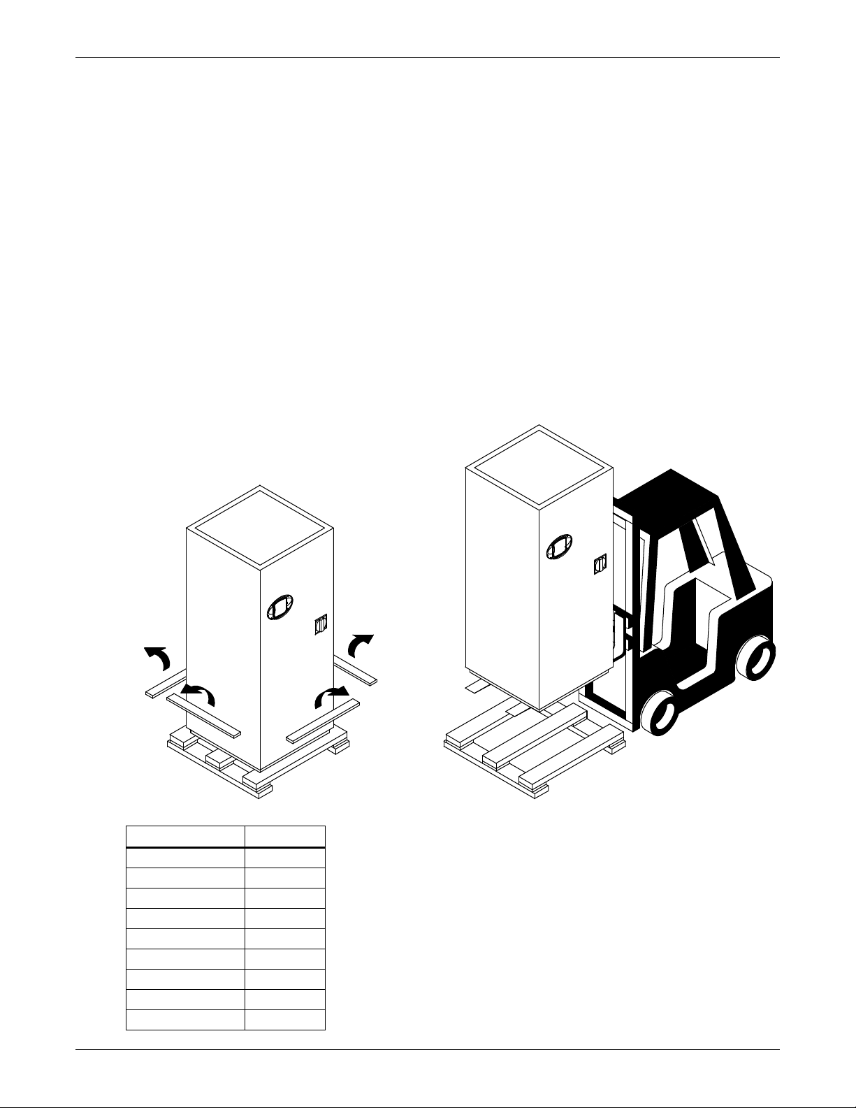
2.4.1 Handling With Skid
Remove plywood skirting holding
unit and skid in place.
Raise unit with fork lift
or similar machine.
• Always keep the unit upright, indoors and protected from damage.
• If possible, transport the unit using a fork lift; otherwise, use a crane with belts or cables, avoiding pressing on the top edges of the packaging.
• If using a fork lift, make sure the forks, if adjustable, are spread to the widest allowable distance
to still fit under the skid.
NOTICE
Risk of overhead interference. Can cause unit and/or structure damage. Refer to the
installation plans prior to moving the unit to verify clearances.
While on the skid, the unit is too tall to fit through a standard height doorway (83 inches or
2108 mm tall). Any attempt to move the unit, while on the skid, through a standard doorway
will cause damage to the unit.
2.4.2 Removal of Skid
• Remove the plywood skirting that keeps the skid and unit in place.
• Raise the Challenger 3000 off the skid. Liebert recommends using a fork lift (see Figure 1)
or similar machine to ensure that the unit is lifted properly.
• Once the unit is raised, the skid can be removed.
Figure 1 Removing Challenger from skid
Installation (Applicable to all Models)
Table 1 Unit net weight
Model Lb (kg)
036E/035E 535 (243)
060E/059E 545 (247)
042A/040A 615 (279)
067A/065A 670 (304)
046WG/045WG 700 (318)
071WG/070WG 750 (340)
061G/058G 785 (356)
068C/072C 545 (247)
102C/101C 555 (252)
6
Page 13
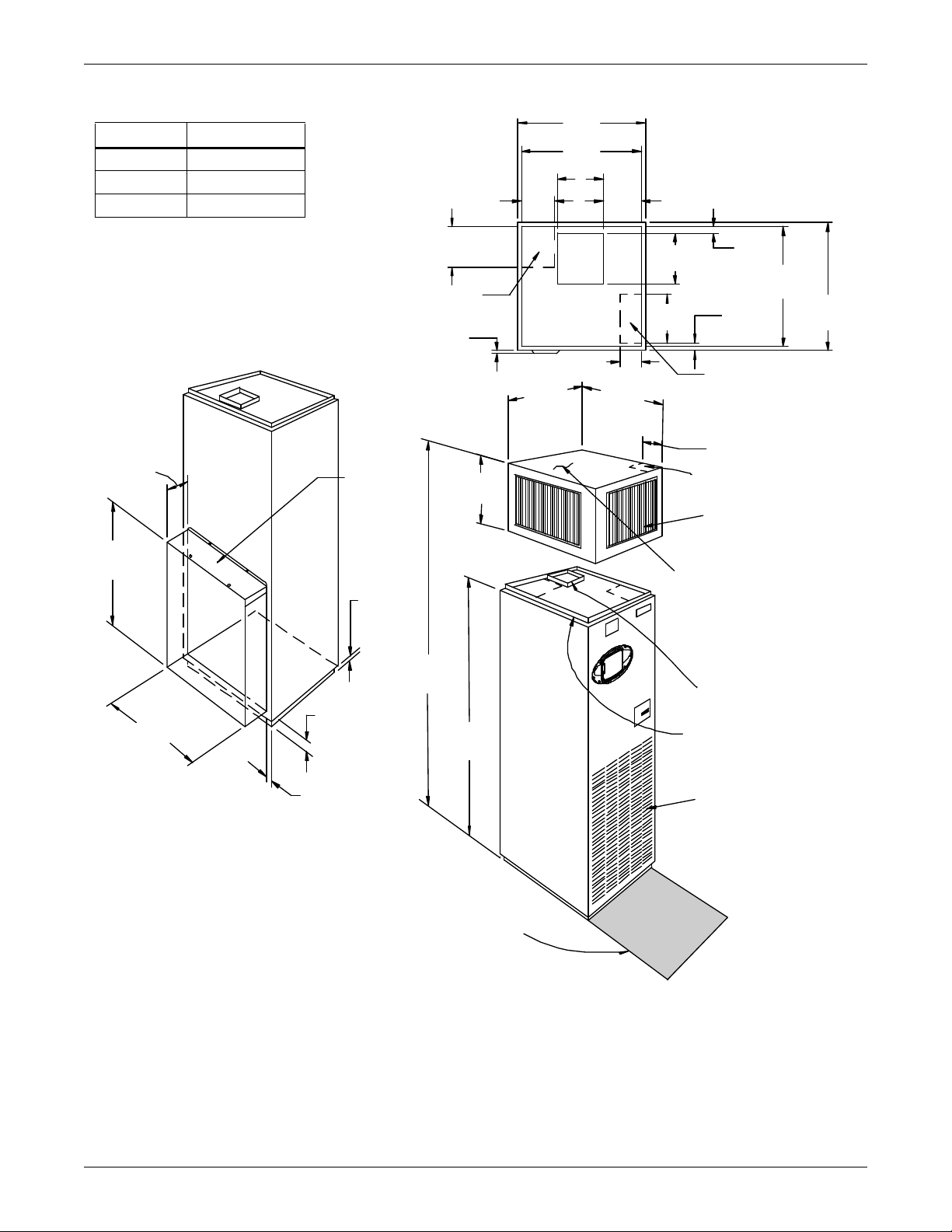
Figure 2 Upflow (BU) cabinet dimensions
A
Shaded area indicates a recommended
clearance of 34" (864mm) for component
access. Right side access s uggested for
GLYCOO L units.
DPN000350
Rev. 01
FRONT VIEW
(front return configuration)
32-1/2"
(826mm)
Overall
Dimension
32-1/2"
(826mm)
Overal l
Dimension
32-1/2"
(826mm)
32-1/2"
(826mm)
Blow er Outlet with
1" (25.4mm) Flange
7/8" (22.2mm) Flange for
Duct or Plenum Connection
Return Air Louvers
Plenum available w it h:
-2, 3 or 4 grilles.
-Solid sides w ith a 7/8" (22mm)
duct flange on top.
Standard Piping Location
Standard Elec trical Outlet
Location Through Unit
Standard Elec trical Outlet
Location Through Plenum
29-3/4"
(756mm)
1-5/8"
(41mm)
9-5/8"
(244mm)
30-1/2"
(775mm)
30-1/2"
(775mm)
1-7/8"
(48mm)
12-1/2"
(318mm)
5-1/2" (140mm)
8-1/2"
(216mm)
Filter Access
Through Top
7-1/2"
(191mm)
29"
(737mm)
2-1/2"
(67mm)
1-3/4 "
(44mm)
REAR VIEW
(rear return configuration)
94"
(2388mm)
76"
(1930mm)
6-7/8" (175mm)
10-1/4"
(260mm)
18"
(457mm)
Projec tion of D isplay
Bezel 5/8" (16mm)
Air Discharge Grille
1" (25mm)
FRONT &
SIDES
3/4" (19mm)
REAR
13"
(330mm)
UNIT
TOP VIEW
A
STD 3 & 5T 11-3/4 (299mm)
Hi Static 3T 8 5/8 (219mm)
Hi Static 5T 11-3/4 (299mm)
Installation (Applicable to all Models)
7
Page 14
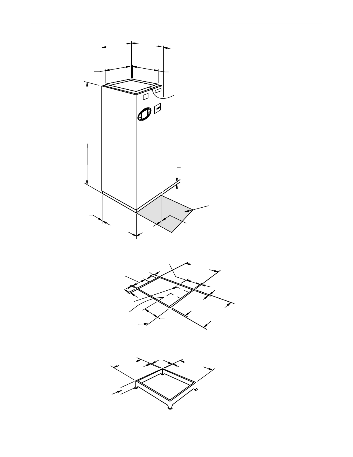
Figure 3 Downflow (BF) cabinet dimensions
Shaded area indicates
a recommended clearance of
34” (864mm) for component
access. Right side access
suggested for GLYCOOL units
DPN000351
Rev. 01
32-1/2"
(826mm)
Overall
Dimension
32-1/2"
(826mm)
Overall
Dimension
30-1/2"
(775mm)
76"
(1930mm)
30-1/2"
(775mm)
30-1/2"
(775mm)
30-1/2"
(775mm)
30-1/2"
(775mm)
30-1/2"
(775mm)
30-1/2"
(775mm)
30-1/2"
(775mm)
Projection of Display
Bezel 5/8" (16mm)
Optional 1-5/8" (41mm)
Flange for Duct or
Plenum Connection
1"
(25.4mm)
1"
(25.4mm)
1"
(25.4mm)
1"
(25.4mm)
FLOOR CUTOUT DIMENSIONS
8"
(203mm)
9"
(229mm)
OPTIONAL FLOOR STAND DIMENSIONAL DATA
4"
(102mm)
1" (25.4mm)
28-1/2"
(724mm)
12"
(305mm)
Floor
Level
Standard Piping
Location
Standard Electrical Location
See Specification
Sheet for Floor Stand
Height Ordered.
1" (25mm) FRONT & SIDES
3/4" (19mm) REAR
Installation (Applicable to all Models)
8
Page 15
2.5 Piping Considerations
All piping below the elevated floor must be located so that it offers the least resistance to air flow.
Careful planning of the piping layout under the raised floor is required to prevent the air flow from
being blocked. When installing piping on the subfloor, it is recommended that the pipes be mounted in
a horizontal plane rather than stacked one above the other. Whenever possible, the pipes should be
run parallel to the air flow.
Condensate pumps for downflow units are shipped separately to be field-installed under the raised
floor. Pump height is 11 inches (279 mm).
2.5.1 Drain Line
A 3/4" (19.1 mm) female pipe thread (FPT) connection is provided for the evaporator coil condensate
drain. This drain line also drains the humidifier, if applicable. The drain line must be located so it will
not be exposed to freezing temperatures. The drain should be at least the full size of the drain connection and pitched a minimum of 1/8" per ft. (11 mm per meter).
NOTE
This line may contain boiling water. Select appropriate drain system materials.
The drain line must include one and only one trap. Units without a condensate pump have a
factory-supplied trap in the unit, so a field trap should not be added. Units with a condensate
pump will require a field-supplied trap downstream from the pump. The drain line must
comply with all applicable codes.
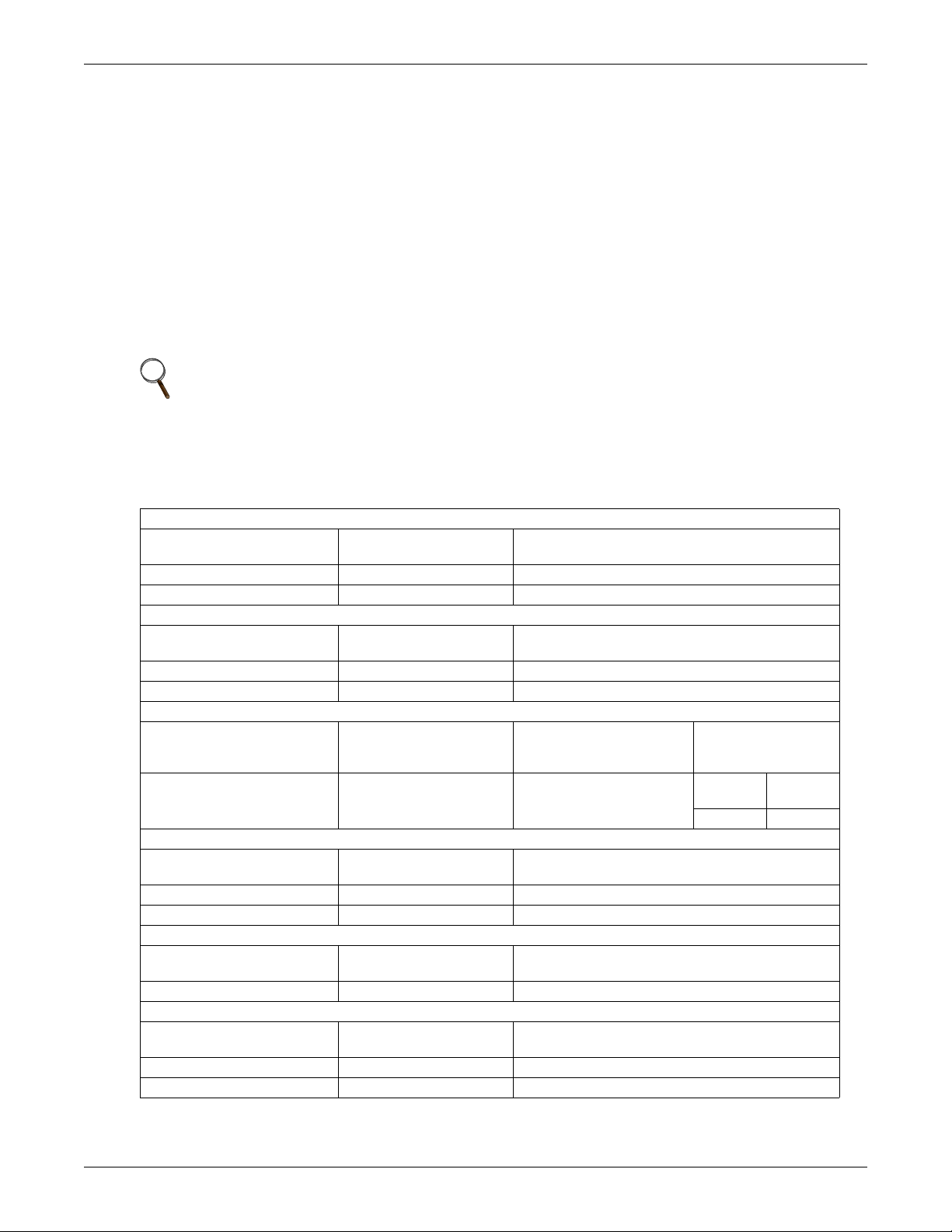
Table 2 Piping connection size
Air-Cooled Unit Connection Sizes—in.
Model No. BF/BU
(50 Hz)
042A (040A) 3/8 5/8
067A (065A) 1/2 7/8
Split System Fan Coil Unit Connection Sizes—in.
Model No. BF/BU (50 Hz) Liquid Line
036E (035E) 5/8 - 18 Female (#6 QC) 1-1/8 - 12 Female (#11 QC)
060E (059E) 1/2 OD Cu 1-1/8 OD Cu
All Units: Connection Sizes—in.
Humidifier Line
OD Copper
H
1/4 3/4 FPT 1/2
Water/Glycol-Cooled Unit Connection Sizes—inches
Model No. BF/BU
(50 Hz)
046WG (045WG) 7/8 7/8
071WG (070WG) 1-1/8 1-1/8
GLYCOOL Unit Connection Sizes —in.
Model No. BE/BK
(50 Hz)
061G (058G) 1-1/8 1-1/8
Chilled Water Unit Connection Sizes—in.
Model No. BF/BU
(50 Hz)
068C (072C) 1-1/8 1-1/8
102C (101C) 1-1/8 1-1/8
Liquid Line O.D. Copper
L
L
Condensate
Drain Line
C
Supply Line
S
Supply Line
S
Supply Line
CWS
Installation (Applicable to all Models)
Hot Gas Line OD Copper
HG
Suction Line
SC
Condensate Pump Line
OD Copper
P
Return Line
Return Line
Return Line
CWR
Hot Water Reheat
Supply
HWS
5/8 5/8
R
R
OD Copper
Return
HWR
9
Page 16
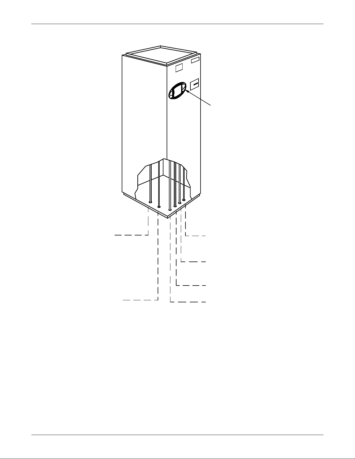
Figure 4 Piping connections for air-cooled units - Downflow models
PIPING OUTLET LOCATIONS
(See Cabinet and Floor Planning
Dimensional Data for Piping
Opening Sizes.)
Liebert iCOM
Control Panel
Condensate Drain 3/4" FP T
Field-pitch a minimum of 1/8" (3.2mm)
per foot (305mm). The drain line
must comply with all applicable codes.
Humidifier Water Supply Line
1/4" OD CU
Hot Gas Refrigerant Line
5/8" OD CU on Models BF042A/BF040 A
7/8" OD CU on Models BF067A/BF065 A
Hot Water Return
5/8" OD CU (optional)
Liquid Refrigerant Line
3/8" OD CU on Models BF042A/BF040 A
1/2" OD CU on Models BF067A/BF065 A
Hot Water Supply
5/8" OD CU (optional)
DPN000353
Rev. 01
Installation (Applicable to all Models)
10
Page 17
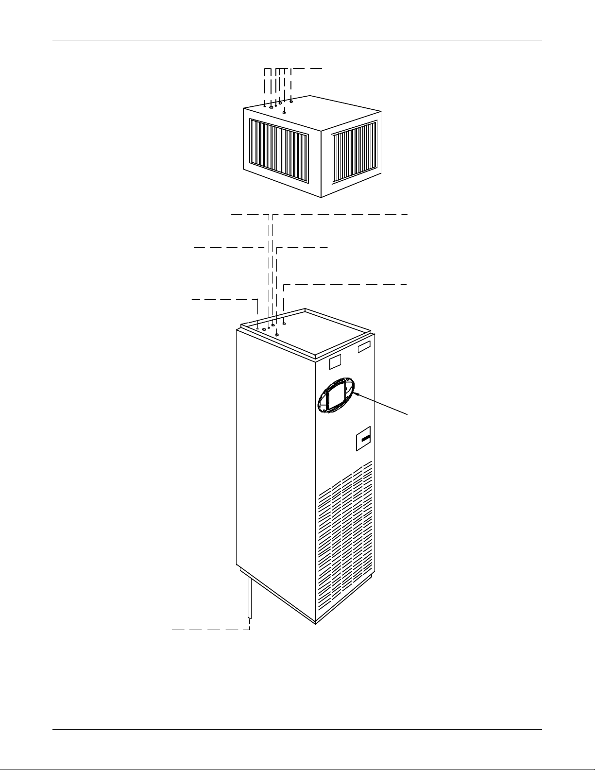
Figure 5 Piping connections for air-cooled units - Upflow models
Condensate Drain
3/4" FPT
Field pitch a min. of 1/8" (3.2mm) per ft. (305mm). Units without
a condensate pump have a factory-supplied trap in the unit, so a
field trap should not be added. Units with a condensate pump will
require a field-supplied trap downstream from the pump.The
drain line must comply with all applicable codes. (If condensate
pump is ordered piping is out top of unit).
DPN000352
Rev. 01
Piping outlet locations through the plenum
are the same as the unit. See below for
descriptions and connection sizes.
Humidifier Water Supply Line
1/4" OD CU
Condensate Pump Line
1/2" OD CU
Used only if optional condensate
pump is ordered.
Hot Water Return
5/8" OD CU (optional)
Liquid Refrigerant Line
3/8" OD CU on Models BU042A/BU040A
1/2" OD CU on Models BU067A/BU065A
Hot Water Supply
5/8" OD CU (optional)
Liebert iCOM
Control
PIPING OUTLET LOCATIONS
(See Cabinet and Floor Planning
Dimensional Data for Piping
Opening Sizes.)
Installation (Applicable to all Models)
11
Page 18
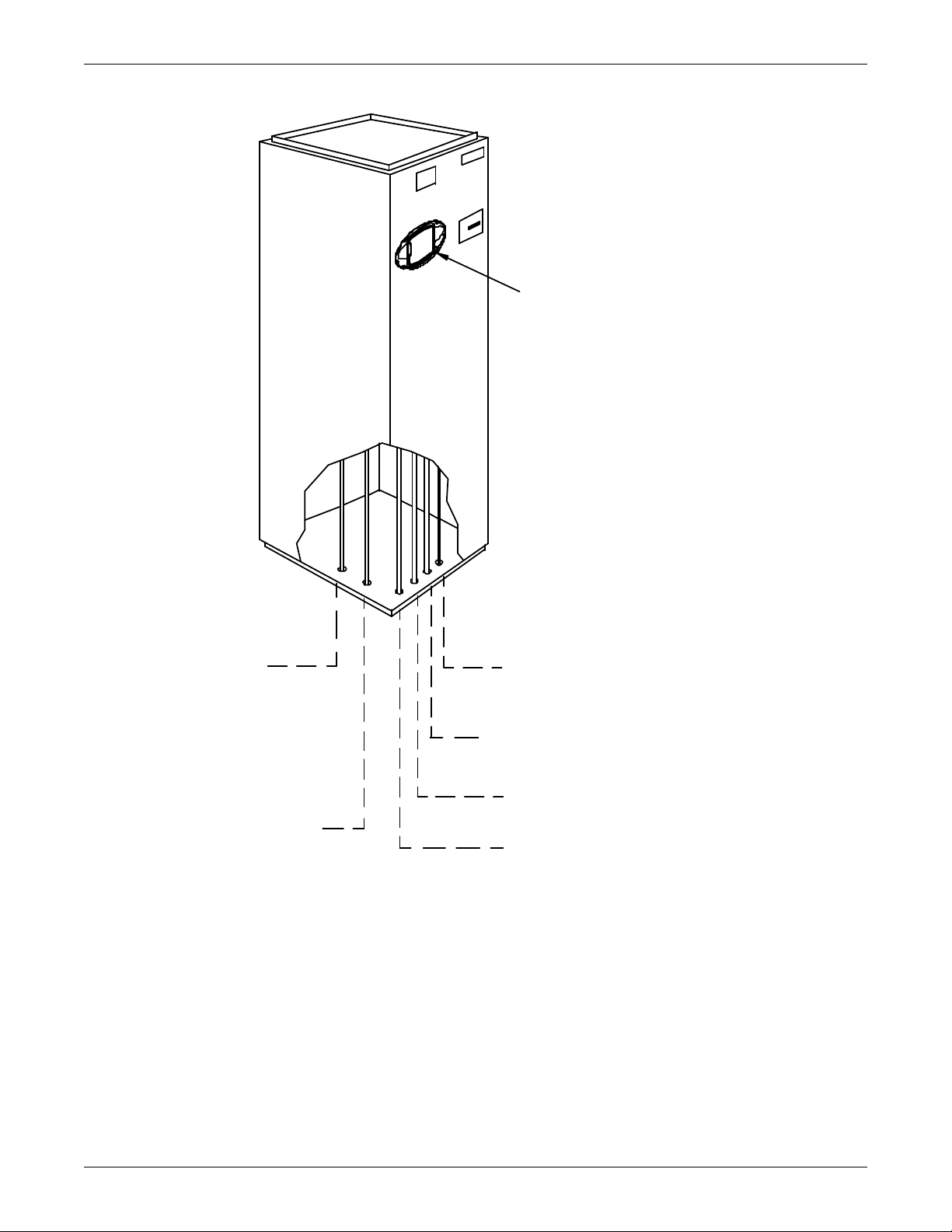
Installation (Applicable to all Models)
PIPING OUTLET LOCATIONS
(See Cabinet and Floor
Planning Dimensional Data
for Piping Opening Sizes.)
DPN000376
Rev. 01
Condensate Drain
3/4" FPT
Field pitch a minimum
of 1/8" (3.2mm) per ft. (305mm).
The drainline must comply
with all applicable codes.
HumidifierWater Supply Line
1/4" OD CU
Suction Refrigerant Line
#11 Quick Connect on Models BF036E/BF035E
1-1/8" OD CU on Models BF060E/BF059E
Hot Water Return
5/8" OD CU (optional)
Liquid Refrigerant Line
#6 Quick Connect on Models BF036E/BF035E
1/2" OD CU on Models BF060E/BF059E
Hot Water Supply
5/8" OD CU (optional)
Liebert iCOM
Control
Figure 6 Piping connections for split system fan coil units - Downflow models
12
Page 19
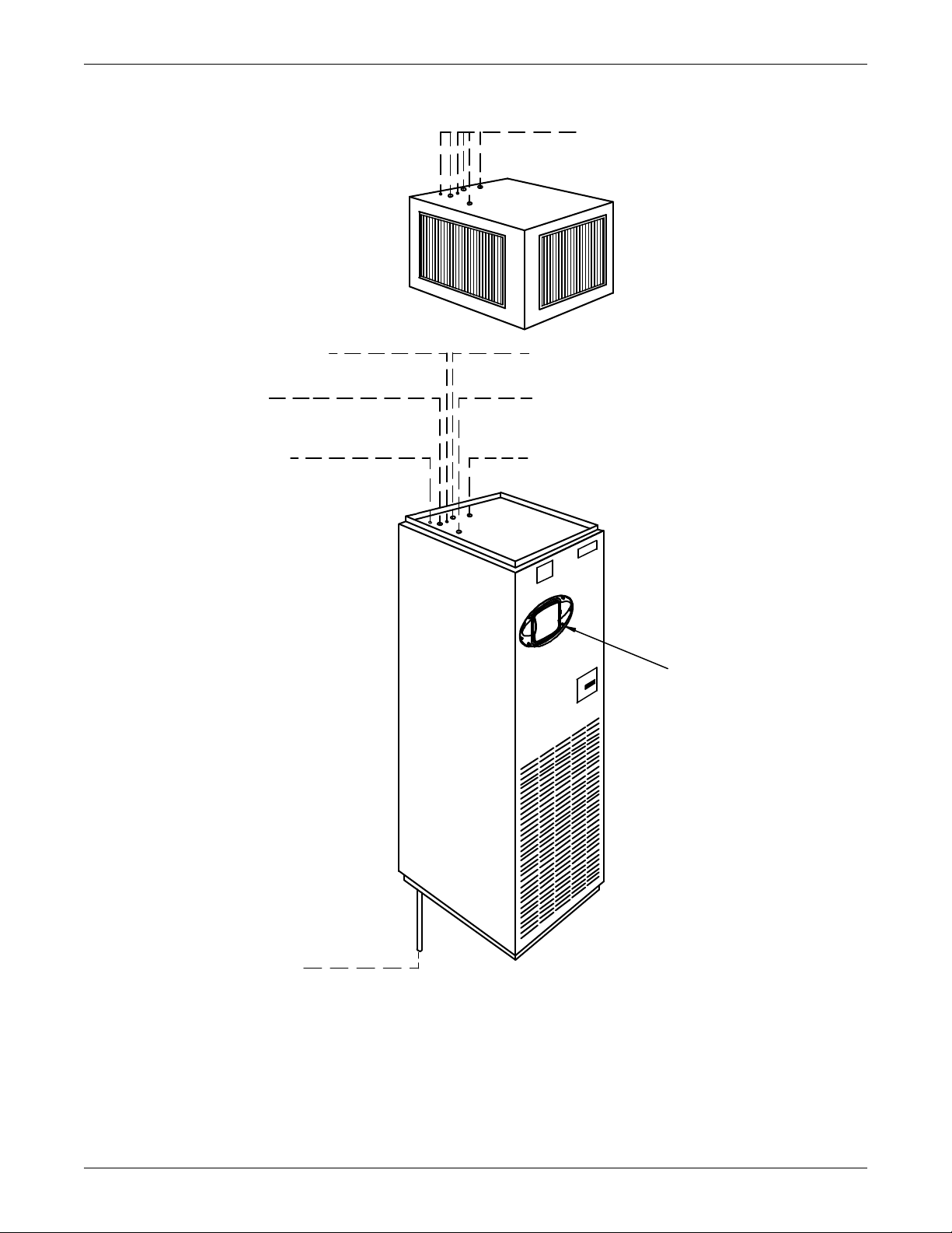
Installation (Applicable to all Models)
DPN000375
Rev. 01
Piping outlet locations through the
plenum are the same as the unit.
See below for descriptions and
connection sizes.
Humidifier Water Supply Line
1/4" OD CU
Condensate Pump Line
1/2" OD CU; used only
if optional condensate pump is ordered.
Hot Water Return
5/8" OD CU (optional)
Liquid Refrigerant Line
#6 Quick Connect on Models BU036E/BU035E
1/2" OD CU on Models BU060E/BU059E
Hot Water Supply
5/8" OD CU (optional)
iCOM Control
Panel
Condensate Drain; 3/4" FPT
Field-pitch a min. of 1/8" (3.2mm) per ft. (305mm). Units without
a condensate pump have a factory-supplied trap in the unit, so a
field trap should not be added. Units with a condensate pump will
require a field-supplied trap downstream from the pump. The
drain line must comply with all applicable codes. (If condensate
pump is ordered, piping is out top of unit).
PIPING OUTLET LOCATIONS
(See Cabinet and Floor Planning
Dimensional Data for Piping
Opening Sizes.)
Figure 7 Piping connections for split system fan coil units - Upflow models
13
Page 20
Installation (Applicable to all Models)
DPN000364
Rev. 01
Condensate Drain
3/4" FPT
Field pitch a minimum
of 1/8" (3.2mm) per ft. (305mm).
The drain line must comply with
all applicable codes
Humidifier Water Supply Line
1/4" OD CU
Condenser Return Line
7/8" OD CU on Models BF046WG/BF045WG
1-1/8" OD CU on Models BF071WG/BF070WG
Hot Water Return
5/8" OD CU (optional)
Condenser Supply Line
7/8" OD CU on Models BF046WG/BF045WG
1-1/8" OD CU on Models BF071WG/BF070WG
Hot Water Supply
5/8" OD CU (optional)
PIPING OUTLET LOCATIONS
(See Cabinet and Floor Planning
Dimensional Data for Piping
Opening Sizes.)
iCOM Control
Panel
Figure 8 Piping connections for water/glycol and GLYCOOL units - Downflow models
14
Page 21
Installation (Applicable to all Models)
Figure 9 Piping connections for water/glycol and GLYCOOL units - Upflow models
Piping outlet locations through the plenum
the same as the unit. See below for
descriptions and connection sizes.
Humidifier Water Supply Line
1/4" OD CU
Condenser Return Line
7/8" OD CU on Models BU046WG/BU045WG
1-1/8" OD CU on Models BU071WG/BU070WG
Condensate Pump Line
1/2" OD CU
Used only if optional condensate
pump is ordered.
Hot Water Return
5/8" OD CU (optional)
Condenser Supply Line
7/8" OD CU on Models BU046WG/BU045WG
1-1/8" OD CU on Models BU071WG/BU070WG
Hot Water Supply
5/8" OD CU (optional)
Liebert iCOM
Control
Condensate Drain
3/4" FPT
Field pitch a min. of 1/8" (3.2mm) per ft. (305mm). Units without
a condensate pump have a factory-supplied trap in the unit, so a
field trap should not be added. Units with a condensate pump will
require a field-supplied trap downstream from the pump. The
drain line must comply with all applicable codes. (If condensate
pump is ordered piping is out top of unit).
15
PIPING OUTLET LOCATIONS
(See Cabinet and Floor Planning
Dimensional Data for Piping
Opening Sizes.)
DPN000363
Rev. 01
Page 22
Installation (Applicable to all Models)
Figure 10 Piping connections for chilled water self-contained units - Downflow models
Liebert iCOM
Control
Condensate Drain
3/4" FPT
Field pitch a minimum
of 1/8" (3.2mm) per ft. (305mm).
The drain line must comply
with all applicable codes.
Humidifier Water Supply Line
1/4" OD CU
PIPING OUTLET LOCATIONS
(See Cabinet and Floor Planning
Dimensional Data for Piping
Opening Sizes.)
Chilled Water Supply Line
1-1/8" OD CU
Chilled Water Return Line
1-1/8" OD CU
Hot Water Return
5/8" OD CU (optional)
Hot Water Supply
5/8" OD CU (optional)
DPN000371
Rev. 01
16
Page 23
Installation (Applicable to all Models)
Condensate Drain 3/4" FP T
Field-pitch a min. of 1/8" (3.2mm) per ft. (305mm). Units without
a condensate pump have a factory-supplied trap in the unit, so a
field trap should not be added. Units with a condensate pump will
require a field-supplied trap downstream from the pump. The
drain line must comply with all applicable codes. (If condensate
pump is ordered, piping is out top of unit).
Piping outlet locations through
the plenum are the same as the unit.
See below for descriptions and
connection sizes.
Humidifier Water Supply Line
1/4" OD CU
Chilled Water Supply Line
1-1/8" OD CU
Condensate Pump Line
1/2" OD CU; used only if optional
condensate pump is ordered.
Hot Water Return
5/8" OD CU (optional)
Chilled Water Return Line
1-1/8" OD CU
Hot Water Supply
5/8" OD CU (optional)
iCOM Control
Panel
DPN000370
Rev. 01
PIPING OUTLET LOCATIONS
(See Cabinet and Floor Planning
Dimensional Data for Piping
Opening Sizes.)
Figure 11 Piping connections for chilled water self-contained units - Upflow models
17
Page 24
2.5.2 Humidifier Supply Water—Optional Infrared
!
• 1/4" supply line; maximum water pressure is 150 psi (1034kPa)
• Size humidifier supply line for 1 gpm (3.8 l/m), with a minimum water pressure of 20 psi (138kPa)
• Do not supply de-ionized water to the humidifier
2.6 Facility Fluid and Piping Maintenance
Facility water and glycol quality remain a requirement throughout the life of the piping system. Fluid
and piping system maintenance schedules must be established and performed. A local fluid maintenance program must be established that will evaluate fluid chemistry and apply necessary treatment.
A periodic leak inspection of facility and unit fluid piping is recommended. Refer to 5.4 - Glycol Pip-
ing.
2.7 Electrical Connections
Three-phase electrical service is required for all models in either 208, 230, 460, or 575 V, 60 Hz; or
200, 230, or 380/415 V, 50 Hz. Electrical service shall conform to national and local electrical codes.
Refer to equipment nameplate regarding wire size and circuit protection requirements. Refer to electrical schematic when making connections.
A manual electrical disconnect switch should be installed within 5 feet (1.6 m) of the unit in accordance with codes, or a factory-supplied disconnect switch may be factory mounted within the unit
accessible from the exterior.
Installation (Applicable to all Models)
WARNING
Risk of electric shock. Can cause injury or death.
Potentially lethal voltages exist within this equipment during operation. Observe all cautions
and warnings on unit and in this manual.
The Liebert iCOM microprocessor does not isolate power from the unit, even in the “Unit Off”
mode. The only way to ensure that there is NO voltage inside the unit is to install and open a
remote disconnect switch. Refer to unit electrical schematic.
NOTICE
Risk of improper scroll compressor installation. Could cause poor performance and
compressor damage.
Three-phase power must be connected to the unit line voltage terminals in the proper
sequence so that the scroll compressor rotates in the proper direction. Rotation in the wrong
direction will result in poor performance and compressor damage. Use a phase sequence and
motor rotation sensor to ensure that the three-phase power is correctly connected and the
compressor is rotating properly.
18
Page 25
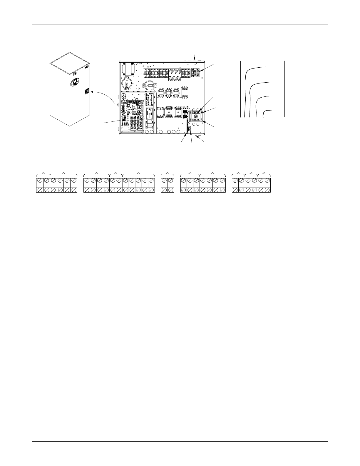
Figure 12 Electrical connections
88
89
84
85
82
83
91 92931234
7877
3738B37B38C37C9796
95
94
7675
565551
50
24
38
Electrical Handy Box
(factory-installed with cover;
inside unit on top for upflow
and on base for downflo w.)
1
2
3
4
5
15
1
6
7
8
DPN000354
Rev. 01
14 14 9 9 10 11 13 12 16 17 18
70
73
72
71
Installation (Applicable to all Models)
1. Electric conduit knockouts on top and bottom of electric box. Knockout size 1-3/4" (44.5mm).
2. Three-phase connection. Electric service connection terminals when factory disconnect is NOT
supplied.
3. Three-phase connection. Electric service connection terminals when factory disconnect switch
is supplied.
4. Factory-installed disconnect switch. (Optional).
5. Three-phase electric service field-supplied.
6. Earth ground connection (50/60Hz). Connection terminal for field-supplied earth grounding
wire.
7. Earth ground bar (50Hz only). Connection terminals with factory ground from each high
voltage component for field supplied earth grounding wire.
8. Control and monitoring section of electric box.
9. Remote unit shutdown. Replace existing jumper between Terminals 37 + 38 with normally
closed switch having a minimum 75VA, 24VAC rating. Use field-supplied Class 1 wiring. Two
additional contact pairs available as an option (labeled as 37B & 38B, 37C & 38C). Replace
existing jumper for appropriate pair as done for 37 & 38.
10. Special alarm connections. Field-supplied 24V Class 1 wiring for special alarm. Connection
made by adding normally open contacts between terminals 24 + 50. Special alarm connections
may be factory-wired or field-wired. See schematic for factory wired special alarms. For
field-wired special alarms, use 24V Class 1 wiring to connect normally open contacts between
Terminals 24 & 50, 24 & 51, 24 & 55, or 24 & 56.
11. SiteScan connection. Terminals 77 (-) and 78 (+) are for connection of a 2-wire, twisted pair,
communication cable (available from Liebert or others) to optional Liebert SiteScan
12. Remote condensing unit connection. Field-supplied 24V Class 1 wiring to remote condensing
unit Terminals 1, 2, 3, & 4 from (R2) relay (split system only).
®
.
13. Smoke detector alarm connections. Field-supplied 24V Class 1 wiring to remote alarm
circuits. Factory-wired contacts from optional smoke detector are #91-comm., #92-NO, and
#93-NC.
14. Common alarm connection. Field-supplied 24V. Class 1 wiring to common alarm Terminals
75 + 76 (and optional 94 + 95, and 96 + 97), which are factory-connected to common alarm relay
(R3).
19
Page 26
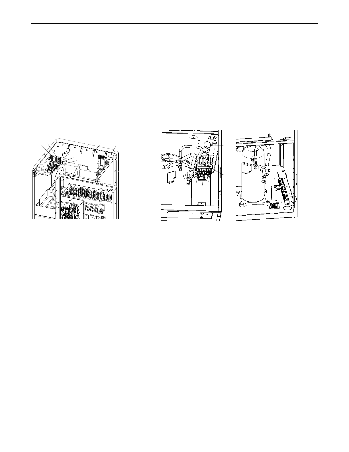
15. Heat rejection connection. Field-supplied 24V Class 1 wiring to interlock heat rejection from
DPN001733
Rev. 0
23
24
22
21
20
19
25
DPN001734
Rev. 0
22
24
23
20
19
25
Upflow Models with Liebert iCOM Downflow Models with Liebert iCOM
pigtails 70 + 71 which are factory-connected to compressor side switch (self-contained units only)
or to GLYCOOL relay (K11, GLYCOOL units only). On Dual Cool units only, pigtails 72 + 73
connect auxiliary cooling source to GLYCOOL relay K11.
16. Reheat and Humidifier Lockout. Optional emergency power lockout of reheat and/or
humidifier: connections provided for remote 24V AC source.
17. Main Fan Auxiliary Switch. Optional main fan auxiliary side switch. Terminals located in field
wiring compartment for remote indication that the evaporator fan motor/unit is on. Field to
connect 24V maximum.
18. Optional Condensate Alarm (Dual Float Condensate Pump only). Relay terminals located in
field wiring compartment for remote indication.
Refer to specification sheet for full load amp. and wire size amp. ratings.
Figure 13 Electrical field connections for Liebert iCOM
Installation (Applicable to all Models)
19. Network Cable “C” Connection. Eight-wire Ethernet cable from U2U networking switch.
20. Network Cable “D” connection. Eight-wire Ethernet cable from U2U networking switch.
Cable “D” connection supplied on units with large Liebert iCOM display only.
21. Opening for Field Wiring. Suggested entry point for all field wiring to unit. Hole size Ø2.5"
(63.5mm)
22. Loose Wire Ties. To secure field-supplied network cables. Tighten after all field-supplied wires
have been installed.
23. Vacant Liebert IntelliSlot
®
. May contain optional Liebert IntelliSlot cards.
24. Populated Liebert IntelliSlot. Optional Liebert IntelliSlot cards may be placed in either of the
two supplied Liebert IntelliSlot locations.
25. Remote Temperature / Humidity Sensor Connection. Six-wire CAN cable supplied with
optional remote T/H sensor
20
Page 27
2.8 Balancing the Air Distribution
2.8.1 Under-Floor Discharge Systems
The systems are designed for constant air delivery, therefore any unusual restrictions within the air
circuit must be avoided. For under-floor air distribution, observe the following guidelines:
• Select the air supply grilles and perforated panels for the raised floor to ensure minimum loss of
pressure in the circuit. Air volume dampers on grilles, which extend several inches below the surface of the raised floor, are usually detrimental to airflow.
• Consideration of the height of the damper on the grille in conjunction with the floor height will
determine whether this type of grille may be used.
• The grilles used in raised floors vary in size, the largest being approximately 18" x 6"
(457 x 152 mm). A larger grille size would be detrimental to the structural capacity of the raised
floor panel. An 18" x 6" (457 x 152 mm) heavy duty, pencil-proof type grille typically has 56 square
inches (0.036 m
• Perforated panels are available from various manufacturers of raised floors. These panels are
usually 2' x 2' (610 x 610 mm) square and have a nominal free area of approximately 108 to 144
square inches (0.07 to 0.09 m
have only 36 to 40 square inches (0.023 to 0.026 m
panels.
• Avoid floor elevations below 7-1/2" (190.5 mm), loosely installed flooring systems, and below-floor
obstructions such as: electrical wiring chases, unusually long electronic system cables, or piping
clusters.
• Always check specifications of the floor supplier before specifying the total number of perforated
panels and grilles required to handle the air flow. The proper specifications for grilles and perforated panels should indicate the total free area required for air delivery rather than the number
of panels and grilles. (See Table 3 for recommended free area required for each model.) This table
indicates the recommended free area based on having the supply air grilles and perforated panels
sized to handle approximately 75% of the total cubic feet per minute (CFM) of the units at a velocity of 550 to 600 ft./min. (2.8 - 3.1 m/s). The remaining 25% of the air flow in the raised floor
passes through cable cutouts, cracks between the panels, and other leakage areas.
2
) of free area.
2
). Use caution in selecting perforated panels as some manufacturers
Installation (Applicable to all Models)
2
) of free area, requiring four times as many
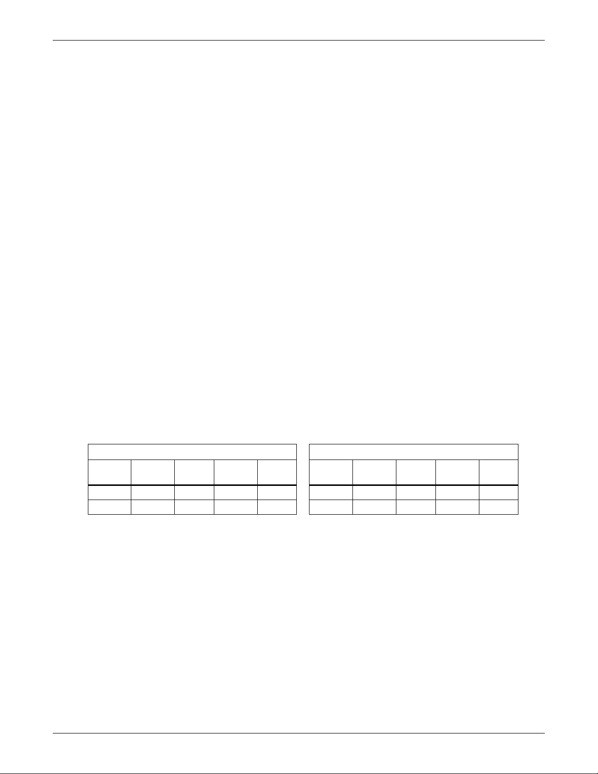
Table 3 Recommended free area ft
550 and 600 fpm (2.8 and 3.1 m/s)
50 Hz Units 60 Hz Units
550
Model
3-ton 2.5 (0.01) 2.3 (0.01) 3-ton 2.5 (0.01) 2.3 (0.01)
5-ton 3.5 (0.02) 3.3 (0.02) 5-ton 3.8 (0.02) 3.5 (0.02)
FPM
2.8.2 Ducted Applications
For ducted supply applications on upflow units, the duct work should be attached to the blower discharge flanges of the unit. For ducted return air applications, the duct work should be attached to the
filter box flanges on upflow rear return units and on the unit top flange for downflow units. Refer to
Figure 2 for information on upflow units and to Figure 3 for downflow units.
The duct work on upflow units must allow access to the motors/blowers for maintenance. The duct
work on upflow units must be designed within the capacity of the unit, otherwise air flow and performance will be compromised.
2.8.3 Plenum Installation
A solid plenum or plenum with discharge grille(s) may be installed. The plenum and instructions for
its installation ship separately from the unit.
2.8
m/s
600
FPM
2
(m2) for grilles or perforated panels at output velocities of
3.1
m/s Model
550
FPM
2.8
m/s
600
FPM
3.1
m/s
21
Page 28

2.9 Checklist for Completed Installation
___ 1. Unpack and check received material.
___ 2. Proper clearance for service access has been maintained around the equipment.
___ 3. Equipment is level and mounting fasteners are tight.
___ 4. Piping completed to refrigerant or coolant loop (if required). Piping has been leak checked,
evacuated and charged (if required).
___ 5. Check piping within the unit & outside of the unit. Remove potential of rub-through or
chaffing.
___ 6. Condensate pump installed (if required).
___ 7. Drain line connected.
___ 8. Water supply line connected to humidifier (if required).
___ 9. Field provided pan with drain installed under all ceiling mounted fluid condensing units (if
installed).
___ 10. Filter box installed (if applicable).
___ 11. Ducting completed (if applicable).
___ 12. Filter(s) installed.
___ 13. Line voltage to power wiring matches equipment serial tag.
___ 14. Power wiring connections completed between disconnect switch, evaporator and condensing
unit, including earth ground.
___ 15. Power line circuit breakers or fuses have proper ratings for equipment installed.
___ 16. Control wiring connections completed to evaporator and condensing unit.
___ 17. Verify water detection is properly installed around all units (if installed).
___ 18. All wiring connections are tight.
___ 19. Control panel DIP switches set based on customer requirements.
___ 20. Foreign materials have been removed from, in and around all equipment installed (literature,
shipping materials, construction materials, tools, etc.).
___ 21. Fans and blowers rotate freely.
___ 22. Inspect all piping connections for leaks during initial operations. Correct as needed.
___ 23. Verify that a blank startup sheet has been sent with the unit(s) and is ready to be completed
by the installer.
Installation (Applicable to all Models)
22
Page 29
Air-Cooled Models—Self-Contained Compressor
!
3.0 AIR-COOLED MODELS—SELF-CONTAINED COMPRESSOR
3.1 Condenser Location
The air-cooled condenser should be located for maximum security and maintenance accessibility.
Avoid ground level sites with public access or areas that contribute to heavy snow or ice accumulations. Utilize centrifugal condensers whenever interior building locations must by used. To assure
adequate air supply, it is recommended that condensers be located in a clean air area, away from
loose dirt and foreign matter that may clog the coil. In addition, condensers should not be located in
the vicinity of steam, hot air, or fume exhausts. Also, condensers should be located no closer than
three feet (1 meter) from a wall, obstruction, or adjacent unit.
NOTE
If the condenser is located below the level of the room unit, the factory should be consulted.
Install condensers in a level position to assure proper refrigerant flow and oil return. For roof installation, mount condensers on steel supports in accordance with local codes. To minimize sound and
vibration transmission, mount steel supports across load bearing walls. For ground installation, a
concrete pad will provide adequate support. Condenser legs have mounting holes for securing the condenser to the steel supports or concrete pad.
3.2 Electrical Connections
Refer to equipment nameplate regarding wire size and circuit protection requirements. Refer to electrical schematic when making connections. Make all wiring and electrical connection in accordance
with local and national codes.
WARNING
Risk of electric shock. Can cause injury or death.
Potentially lethal voltages exist within this equipment during operation. Observe all cautions
and warnings on unit and in this manual.
The Liebert iCOM microprocessor does not isolate power from the unit, even in the “Unit Off”
mode. The only way to ensure that there is NO voltage inside the unit is to install and open a
remote disconnect switch. Refer to unit electrical schematic.
Use voltmeter to make sure power is turned off before making any electrical connections.
3.2.1 Line Voltage
Line voltage electrical service is required for all air-cooled condensers at the location of the condenser.
This power supply does not have to be the same voltage as the indoor unit. This separate power source
may be 208, 230, 460, or 575 V, 60 Hz; or 200, 230, or 380/415 V, 50 Hz. The disconnect switch may be
factory-supplied and mounted in the electrical panel or field-supplied and mounted per local and
national codes.
3.2.2 Low Voltage
A control interlock between the condenser and the indoor unit is required and is connected between
70 and 71 in the handy box of the indoor unit and the electric panel of the air-cooled condenser. NEC
Class 1 wiring is required.
3.2.3 Liebert Lee-Temp/Flood Back Head Pressure Control Condensers
Liebert Lee-Temp condensers require a separate power supply for the heated receivers. This power
supply is connected to the electrical connection box on the end of the receiver.
23
Page 30
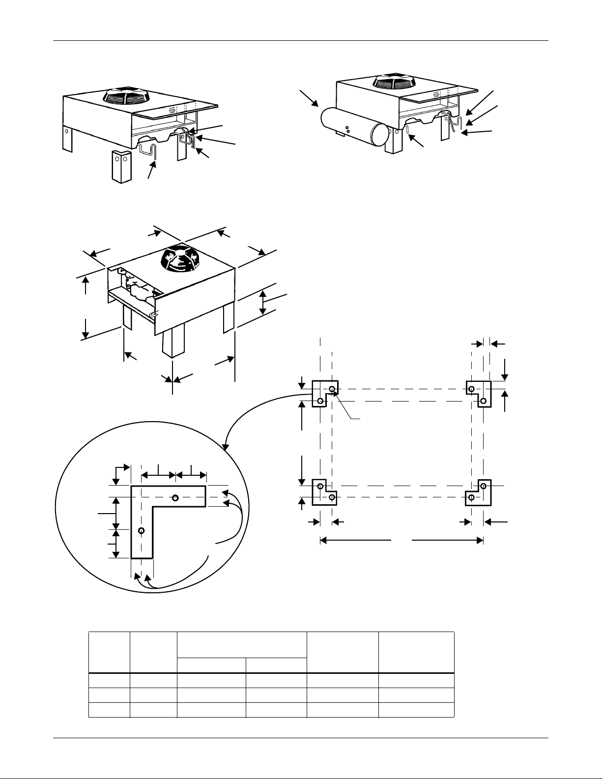
Figure 14 Air-cooled condensers
Secure each leg to condenser frame at all
points shown using hardware provided.
Liquid line
* B
TYPICAL FOOTPRINT
Liebert Lee-Temp heater
pad connection box
*B - Inverted traps are to be field-supplied and installed
(typ). When installing traps, provide clearance for swing
end of access door. Traps are to extend above base of
coil by a minimum of 7-1/2" (190 mm)
Liquid line
Hot gas line
Electric service
supplied by
others
Electric
service
supplied by
others
Hot gas
line
* B
LIEBERT LEE-TEMP CONDENSER
FAN SPEED AND VFD CONDENSER
44"
(1118mm )
18" (457.2mm)
43-9/16"
(1106mm)
51-7/16"
(1306.5mm)
37-7/8"
(962mm)
Common to all models. See Table 4
below for key to “A” dimension.
CONDENSER MOUNTING
1"
(25.4mm)
1-3/4"
(44.5mm)
4-1/4"
(108mm)
4-1/4"
(108mm)
1-3/4"
(44.5mm)
1"
(25.4mm)
1-3/4"
(44.5mm)
1" typ.
(25.4mm)
1-3/4"
(44.5mm)
37-11/16"
(957.3mm)
1-3/4"
(44.5mm)
A
9/16" (14.3mm)
diameter holes
8 places for
1/2" (12.7mm)
diameter bolts
43-3/16"
(1097mm)
SINGLE FAN AIR-COOLED CONDENSERS
1" typ.
(25.4mm)
Air-Cooled Models—Self-Contained Compressor
Table 4 Air-cooled condenser statistics
Model
083 1 7/8 5/8 295 (133.8) 42 (1067)
104 1 1-1/8 5/8 315 (142.8) 42 (1067)
165 2 1-1/8 7/8 425 (193) 82 (2083)
Number
of Fans
Connection Sizes
(OD Copper)
Net Weight
24
lb (kg)
“A” Dimension
in (mm)Hot Gas (in.) Liquid (in.)
Page 31
3.3 Refrigerant Piping
All refrigeration piping should be installed with high temperature brazed joints. Prevailing good
refrigeration practices should be employed for piping supports, leak testing, dehydration and charging of the refrigeration circuits.
Unit refrigeration components and piping are shipped from the factory with a nitrogen holding
charge.
NOTICE
Risk of improper installation. Can cause equipment and property damage.
The refrigeration piping should be isolated from the building by the use of vibration isolating
supports.
When installing field piping, care must be taken to protect all refrigerant lines from the
atmosphere, especially when using refrigerants with POE oils. Do not allow the piping to
stand open to air for more than 15 minutes. Units designed for R407C have a compressor that
contains POE oil that is very hygroscopic; that is, it quickly absorbs water from the air. The
longer the compressor piping is left open to air, the harder it will be to fully evacuate. If left
open too long, the POE oil may need to be replaced before achieving the required vacuum
level.
Keep the evaporator unit and condenser closed with their factory charge of dry nitrogen while
all field piping is installed. Keep the field piping clean and dry during installation, and do not
allow it to stand open to the atmosphere. When all the field interconnecting piping is in place,
vent the condenser dry nitrogen charge and connect to the field piping. Finally, vent the
evaporator unit dry nitrogen charge and make its piping connections last.
Follow all proper brazing practices including a dry nitrogen purge to maintain system
cleanliness.
Air-Cooled Models—Self-Contained Compressor
NOTE
Piping, including inverted trap(s), must be routed to allow unobstructed access to the panel
per the NEC.
Traps should be installed in the hot gas line on vertical risers at the base and every 25 feet (7.6
meters) in elevation. These traps will collect condensed refrigerant and refrigerant oil during the off
cycle of the unit and ensure flow of refrigerant oil during operation.
A check valve is factory-supplied with the unit to be field-installed on the discharge side of the scroll
compressor. Be sure to install the check valve with the refrigerant flow in the proper direction. When
soldering or brazing the valve, it is very important to protect the internal parts by wrapping the valve
with a damp cloth to keep the valve temperature below 250°F (121°C).
Approval is required whenever:
• a refrigerant piping run exceeds 150 ft. (46 m) equivalent length
• an R407C system condenser must be located below the level of the cooling coil.
Total discharge line pressure drop must not exceed 10 PSIG (69 kPa).
Consult your local Liebert representative when considering installations outside these guidelines.
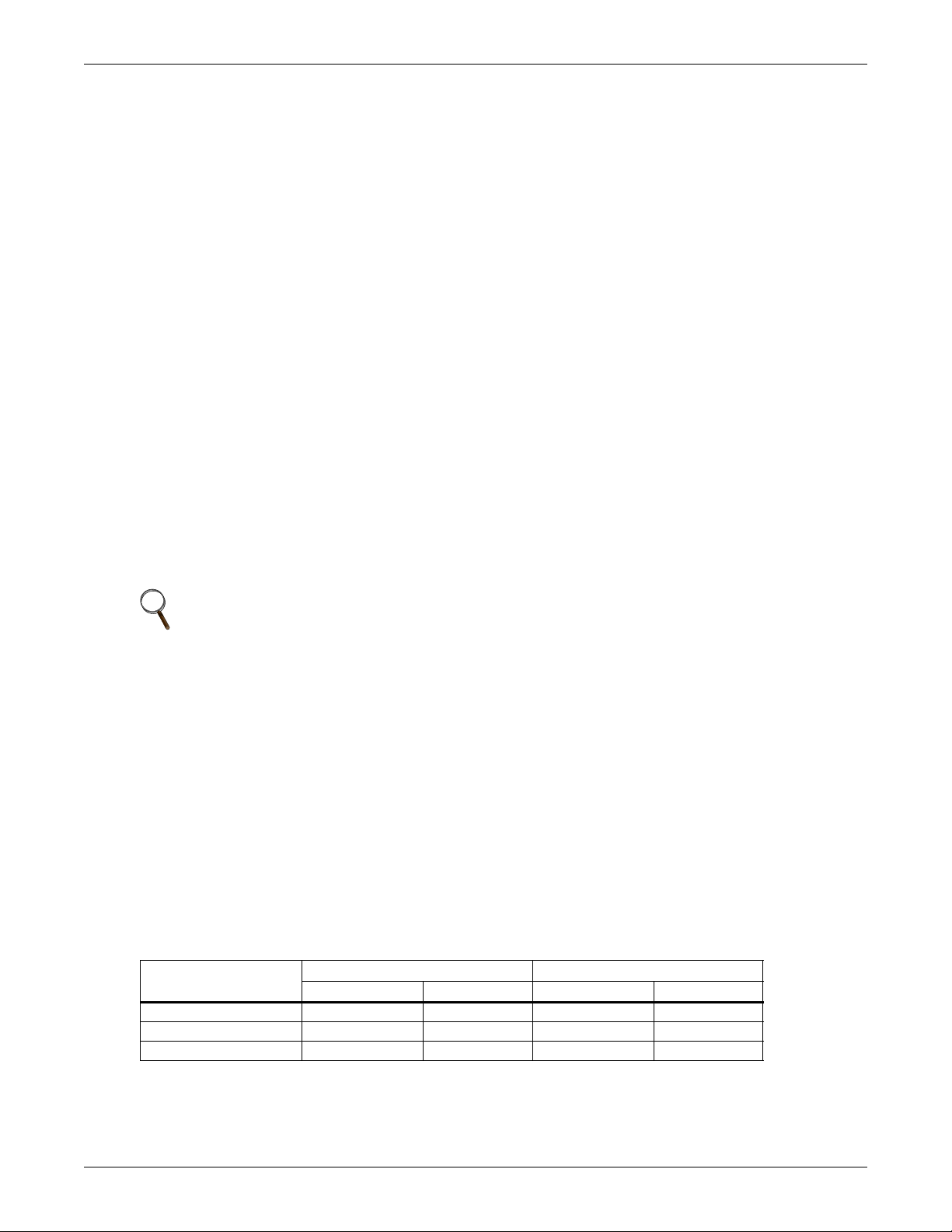
Table 5 Recommended line sizes — OD copper (inches)*
3.5-ton 042A (040A) 5-ton 067A (065A)
Equivalent Length
50 ft. (15 m) 5/8 1/2 7/8 1/2
100 ft. (30 m) 3/4 1/2 7/8 5/8
150 ft. (45 m) 3/4 5/8 7/8 5/8
*Recommended vertical line sizes must be used for proper oil return at all cooling and dehumidification steps.
Hot Gas Line Liquid Line Hot Gas Line Liquid Line
25
Page 32
Air-Cooled Models—Self-Contained Compressor
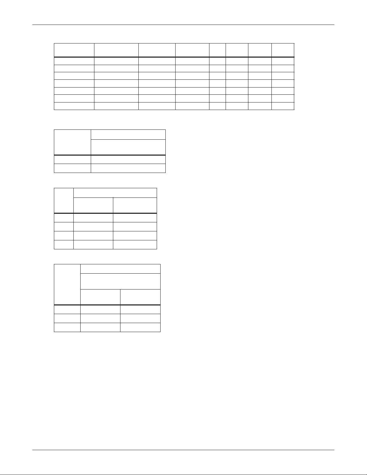
Table 6 Equivalent lengths (feet) for various pipe fittings
Copper Pipe
O.D. in.
1/2 0.8 1.3 0.4 2.5 0.26 7.0 4.0
5/8 0.9 1.4 0.5 2.5 0.28 9.5 5.0
3/4 1.0 1.5 0.6 2.5 0.3 12.0 6.5
7/8 1.45 1.8 0.8 3.6 0.36 17.2 9.5
1-1/8 1.85 2.2 1.0 4.6 0.48 22.5 12.0
1-3/8 2.4 2.9 1.3 6.4 0.65 32.0 16.0
1-5/8 2.9 3.5 1.6 7.2 0.72 36.0 19.5
Refrigerant trap = 4 times equivalent length of pipe per this table.
90 Degree
Elbow Copper
90 Degree
Elbow Cast
45 Degree
Elbow Tee
Gate
Valve
Globe
Valve
Table 7 Indoor unit refrigerant charge lb (kg)
R407C
Model
42A/40A 0.9 (0.4)
67A/65A 1.4 (0.6)
Approximate Charge
lb (kg)
Table 8 Line charges - refrigerant per 100 ft. (30 m) of Type “L” copper tube
R407C
Liquid Line
O.D.
1/2" 7.3 (3.3) 1.3 (0.6)
5/8" 11.7 (5.3) 2.1 (1.0)
3/4" 16.6 (7.5) 3.0 (1.4)
7/8" 24.4 (11.1) 4.4 (2.0)
lb (kg)
Hot Gas Line
lb (kg)
Angle
Valve
Table 9 Condenser refrigerant (per serial tag)
R407C
Approximate Charge
lb (kg)
Liebert
Model
083 8 (3) 25 (12)
104 9 (4) 37 (17)
165 15 (6.8) 50 (22.7)
* Charge includes the receiver charge.
Fan Speed
Lee-Temp*
3.4 Fan Speed Control Systems
The Variable Fan Speed Control systems (FSC & VFD) uses pressure-activated electronic fan speed
control systems and remotely located thermostat(s) to ensure operation at ambient temperatures as
low as 0°F (-18°C). For this ambient temperature range, the VFD Control Condenser must be used
with digital scroll indoor units and can be used for energy savings with any Liebert Challenger 3000
unit.
Variable Fan Speed Control Piping
A discharge line and a liquid line must be field-installed between the indoor unit and the outdoor condenser. See Figures 15 and 16 for details.
26
Page 33
Air-Cooled Models—Self-Contained Compressor
Variable Fan Speed Control Materials Supplied
•Built-in, pre-wired condenser control box
• Air-Cooled condenser
• Piping access cover to be reinstalled when piping is complete
• Bolts—four per leg (3/8" x 5/8")
• Terminal block for two-wire, 24V interlock connection between unit and condenser
• Condenser legs—four with 1-fan, 2-fan and 3-fan models; six with 4-fan models
Variable Fan Speed Control Leak Check and Evacuation Procedure
Proper leak check and evacuation can be accomplished only with all system solenoid valves open and
check valves accounted for.
NOTE
Systems with a scroll or digital scroll compressor include a factory-installed check valve and
an additional downstream Schrader valve with core in the compressor discharge line. Proper
evacuation of the condenser side of the compressor can be accomplished only using the
downstream Schrader valve. See piping schematic (Figures 15 and 16).
1. If unit power is available, open the unit liquid line solenoid valves using the evacuation function
in the diagnostic section of the Liebert iCOM control (refer to the Liebert iCOM user manual,
SL-18835). If unit power is not available, a field-supplied 24VAC / 75VA power source must be
directly connected to each of the unit solenoid valves.
2. For scroll and digital scroll compressors, connect refrigerant gauges to the suction rotalock valves
and discharge line Schrader valves (see Note above) on the compressor.
3. Open the service valves and place a 150 PSIG (1034 kPa) of dry nitrogen with a tracer of
refrigerant. Check system for leaks with a suitable leak detector.
4. After completion of leak testing, release the test pressure (per local code) and pull an initial deep
vacuum on the system with a suitable pump.
5. After four hours, check the pressure readings and, if they have not changed, break vacuum with
dry nitrogen. Pull a second and third vacuum to 250 microns or less. Recheck the pressure after
two hours. After completing this step, proceed to Variable Fan Speed Charging on page 28.
27
Page 34
Air-Cooled Models—Self-Contained Compressor
!
Variable Fan Speed Charging
1. Check unit nameplate for refrigerant type to be used. Unit control configurations differ depending
on refrigerant type.
2. Refrigerant charging requires unit operation. Refer to 2.9 - Checklist for Completed
Installation.
3. Calculate the amount of charge for the system. Refer to the unit, condenser and refrigerant line
charge data in Tables 6, 7, 8 and 9.
4. Weigh in as much of the system charge as possible before starting the unit.
CAUTION
Risk of improper refrigerant charging. Can cause equipment damage.
Refrigerant R407C is a blend of three components and must be introduced and charged from
the cylinder only as a liquid.
When adding liquid refrigerant to an operating system, it may be necessary to add the
refrigerant through the compressor suction service valve. Care must be exercised to avoid
damage to the compressor. Emerson recommends connecting a sight glass between the
charging hose and the compressor suction service valve. This will permit adjustment of the
cylinder hand valve so that liquid can leave the cylinder while allowing vapor to enter the
compressor.
5. Turn on unit disconnect switch. Operate the unit for 30 minutes using the charging function for
the system in the diagnostic section of the Liebert iCOM control (see Liebert iCOM user manual,
SL-18835). The charging function operates the compressor at full capacity and energizes the
blower motor and the liquid line solenoid valve. The reheat and humidifier are disabled. A
minimum 20psig (138kPa) must be established and maintained for the compressor to operate.
The charging function can be reset as many times as required to complete unit charging.
Table 10 Fan speed suction pressure transducer settings
R-407C
Gauge (Sea Level) Absolute
Function
Pump-Down Cutout 20 (138) 35 (241)
Pump-Down Reset 65 (448) 80 (552)
Minimum to Start-Cooling 35 (241) 50 (344)
Low-Pressure Cutout (DX only) 52 (358) 67 (461)
psiG (kPa) psiA (kPa)
6. Charge the unit until the liquid line sight glass becomes clear. Then add one additional pound
(2.2kg) of refrigerant.
NOTE
A digital scroll compressor will have a clear sight glass only when operating at 100% capacity.
When operating below 100%, the sight glass may show bubbles with each 15-second unloading
cycle.
7. As head pressure builds, the variable fan speed controlled condenser fan begins rotating. The fan
will run at full speed when sufficient head pressure is developed—fan starts to rotate at 190 psig
(1310 kPA) and is full speed at 250 psig (1724 kPA).
28
Page 35
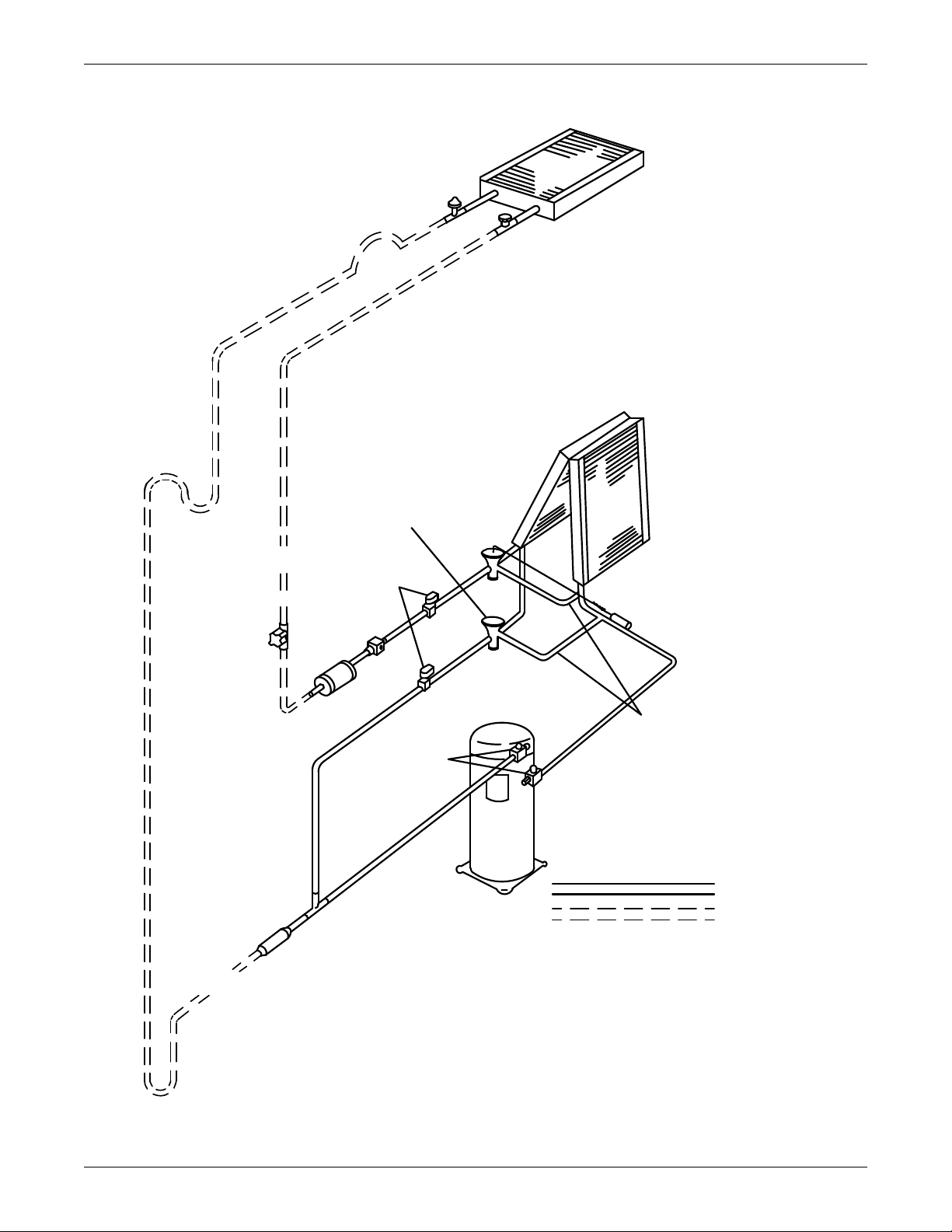
Air-Cooled Models—Self-Contained Compressor
DPN000349
Rev. 3
Condenser
Coil
Schrader
Valve
Fusible
Plug
Evaporator
Coil
Hot Gas
Bypass
Valve
Traps* every
25 ft. (7.6m)
of rise
Solenoid
Valves
Sight
Glass
Filter
Dryer
Liquid Return
Shutoff*
Valve
Sensing
Bulb
External Equalizers
Scroll
Compressor
Service
Valves
Hot Gas
Bypass
Hot Gas
Discharge
Check Valve
FIELD PIPING
FACTORY PIPING
*Components are not supplied by Liebert but
are recommended for proper circuit operation
and maintenance.
Expansion
Valve
Inverted Trap * on
discharge line to
extend above base
of coil by a minimum
of 7-1/2" (190mm)
Figure 15 General arrangement—Air-cooled models with fan speed control
29
Page 36
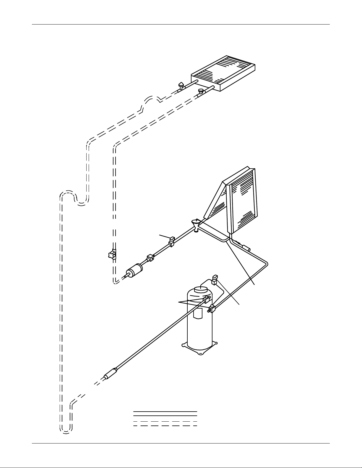
Air-Cooled Models—Self-Contained Compressor
Inverted Trap * on
discharge line to
extend above base
of coil by a minimum
of 7-1/2" (190mm)
Condenser
Coil
Schrader
Valve
Fusible
Plug
Traps* every
25 ft. (7.6m)
of rise
Evaporator
Coil
Expansion
Valve
Solenoid
Valve
Sight
Glass
Filter
Dryer
Liquid Return
Shutoff*
Valve
Sensing
Bulb
External Equalizer
Service
Valve s
Hot Gas
Discharge
Check Valve
FACTORY PIPING
FIELD PIPING
*Components are not supplied by Liebert but
are recommended for proper circuit operation
and maintenance.
Digital
Compressor
Digital
Solenoid Valve
DPN001726
Rev. 0
Figure 16 General arrangement—Air-cooled models with digital scroll and fan speed control
30
Page 37
Air-Cooled Models—Self-Contained Compressor
3.5 Air-Cooled Condenser with Liebert Lee-Temp “Flooded Condenser” Head Pressure Control System
The Liebert Lee-Temp system consists of a modulating type head pressure control valve and insulated
receivers with heater pads to ensure operation at ambient temperatures as low as -30°F (-34.4°C).
The Liebert Lee-Temp system can be used with any compressor choice.
Liebert Lee-Temp Piping
A discharge line and a liquid line must be field-installed between the indoor unit and the outdoor condenser. See Figures 17 and 18 for details.
Liebert Lee-Temp Controlled Materials Supplied
•Built-in, pre-wired condenser control box
• Air-Cooled condenser
• Piping access cover to be reinstalled when piping is complete (models with one to four fans only)
• Bolts—four per leg (3/8" x 5/8")
• Terminal block for two-wire, 24V interlock connection between unit and condenser
• Condenser legs—four with 1-fan, six on two-, three- and six-fan models and eight on four- and
eight-fan models
• Bolts—six per receiver (3/8" x 1")
• Lee-Temp system:
• Insulated storage receiver
• Head pressure control valve with integral check valve
• Service valve
• Pressure relief valve
• Liquid level sight glass
•Check valve
NOTE
Lee-Temp heater pads require a separate, continuous electrical source. See nameplate on unit
for proper voltage.
Lee-Temp Leak Check and Evacuation Procedure
Proper leak check and evacuation can be accomplished only with all system solenoid valves open and
check valves accounted for.
NOTE
Systems with scroll or digital scroll compressors include a factory-installed check valve and an
additional downstream Schrader valve with core in the compressor discharge line. Proper
evacuation of the condenser side of the compressor can be accomplished only using the
downstream Schrader valve. See piping schematic (Figure 18).
1. If unit power is available, open the unit liquid line solenoid valves using the evacuation function
in the diagnostic section of the Liebert iCOM control. If unit power is not available, a fieldsupplied 24VAC / 75VA power source must be directly connected to each of the unit solenoid
valves.
2. Attach a jumper hose from the service valve fitting on the outlet of the receiver and the Schrader
fitting on the discharge header of the condenser. Front-seat the service valve approximately
two (2) turns.
3. For scroll and digital scroll compressors, connect refrigerant gauges to the suction rotalock valves
and discharge line Schrader valves (see Note above).
4. Open the service valves and place a 150 PSIG (1034 kPa) of dry nitrogen with a tracer of
refrigerant. Check system for leaks with a suitable leak detector.
5. After completion of leak testing, release the test pressure (per local code) and pull an initial deep
vacuum on the system with a suitable pump.
31
Page 38
Air-Cooled Models—Self-Contained Compressor
!
6. After four hours, check the pressure readings and, if they have not changed, break vacuum with
dry nitrogen. Pull a second and third vacuum to 250 microns or less. Recheck the pressure after
two hours.
7. Remove the jumper hose installed previously from between the service valve fitting and the
condenser. After completing this step, proceed to Lee-Temp Charging.
Lee-Temp Charging
1. Check unit nameplate for refrigerant type to be used. Unit control configurations differ depending
on refrigerant type.
2. Refrigerant charging requires unit operation. Refer to 2.9 - Checklist for Completed
Installation.
3. Calculate the amount of charge for the system. Refer to the unit, condenser and refrigerant line
charge data in Tables 6, 7, 8 and 9.
4. Weigh in as much of the system charge as possible before starting the unit.
CAUTION
Risk of improper refrigerant charging. Can cause equipment damage.
Refrigerant R407C is a blend of three components and must be introduced and charged from
the cylinder only as a liquid.
When adding liquid refrigerant to an operating system, it may be necessary to add the
refrigerant through the compressor suction service valve. Care must be exercised to avoid
damage to the compressor. Emerson recommends connecting a sight glass between the
charging hose and the compressor suction service valve. This will permit adjustment of the
cylinder hand valve so that liquid can leave the cylinder while allowing vapor to enter the
compressor.
5. Turn on unit disconnect switch. Operate the unit for 30 minutes using the charging function for
the system in the diagnostic section of the Liebert iCOM control. The charging function operates
the compressor at full capacity and energizes the blower motor and liquid line solenoid valve. The
reheat and humidifier are disabled. A minimum 20psig (138kPa) must established and
maintained for the compressor to operate. The charging function can be reset as many times as
required to complete unit charging.
Table 11 Lee-Temp suction pressure transducer settings
R-407C
Gauge Reading
(Sea Level) Absolute
Function
Pump-Down Cutout 20 (138) 35 (241)
Pump-Down Reset 65 (448) 80 (552)
Minimum to Start-Cooling 50 (345) 65 (448)
Low-Pressure Cutout (DX only) 52 (358) 67 (461)
psiG (kPa) psiA (kPa)
6. Charge the unit until the liquid line sight glass becomes clear. Then add one additional pound
(2.2 kg) of refrigerant.
NOTE
A digital scroll compressor will have a clear sight glass only when operating at 100% capacity.
When operating below 100%, the sight glass may show bubbles with each 15-second unloading
cycle.
Lee-Temp Receiver Refrigerant Level
On each receiver at the condenser are two refrigerant-level sight glasses. Refrigerant level will vary
with outside temperature. Check refrigerant level after the unit has been on for at least 15 minutes.
Sight Glass Levels
40°F (4.5°C) and lower—bottom sight glass is 3/4 full
40 to 60°F (4.5 to 15.5°C)—bottom sight glass is full
60°F (15.5°C) and higher—top sight glass is 3/4 full.
32
Page 39
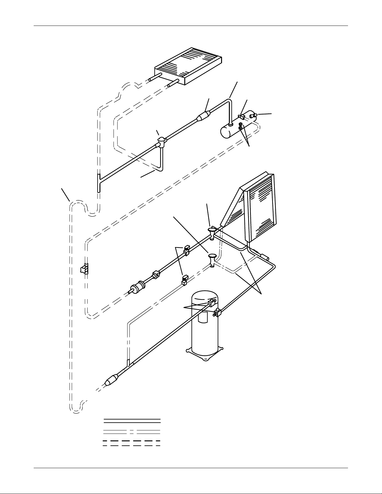
Figure 17 General arrangement—Air-cooled models with Liebert Lee-Temp
* Components are not supplied by Liebert
but are recommended for proper
circuit operation and maintenance.
* * Components supplied by Liebert
and must be field installed.
FACTORY PIPING
FIELD PIPING
Piping Assembly * *
Condenser Coil
Rotalock Valve * *
1/4" ( 6.4mm)
Pressure Relief
Valve * *
Sight Glass
Liebert
Lee-Temp
Receiver
Head Pressure
Control with
Integral Check
Valve
Check
Valve
Evaporator Coil
Sensing Bulb
Expansion
Valve
Hot Gas
Bypass
Valve
Hot Gas
Bypass
Solenoid
Valves
Sight Glass
Filter Dryer
Shutoff
Valve *
Liquid Return
External
Equalizers
Service
Valves
Scroll
Compressor
Liquid Return
from Condenser
Traps * Every
25 Ft. (7.6m)
of rise on Hot
Gas Line only
Inverted Trap * on
discharge line to
extend above base
of coil by a minimum
of 7-1/2" (190mm)
OPTIONAL PIPING
Hot Gas Discharge
Check Valve
DPN000674
Rev. 02
Air-Cooled Models—Self-Contained Compressor
33
Page 40
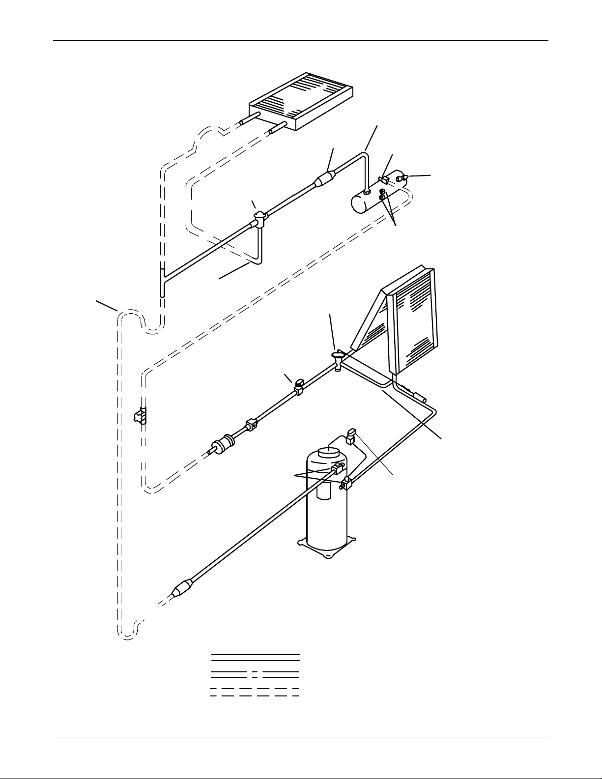
Air-Cooled Models—Self-Contained Compressor
Digital
Solenoid Valve
DPN001725
Rev. 0
* Components are not supplied by Liebert
but are recommended for proper
circuit operation and maintenance.
* * Components supplied by Liebert
and must be field-installed.
OPTIONAL PIPING
FIELD PIPING
FACTORY PIPING
Piping Assembly * *
Condenser Coil
Rotalock Valve * *
1/4" ( 6.4mm)
Pressure Relief
Valve * *
Sight Glass
Liebert
Lee-Temp
Receiver
Head Pressure
Control with
Integral Check
Valve
Check Valve
Liquid Return
from Condenser
Inverted Trap * on
discharge line to
extend above base
of coil by a minimum
of 7-1/2" (190mm)
Traps * Every
25 Ft. (7.6m)
of rise on Hot
Gas Line only
Evaporator Coil
Sensing Bulb
Expansion Valve
Solenoid Valve
Sight Glass
Filter Dryer
Liquid Return
Shutoff
Valve *
External Equalizer
Service
Valves
Digital
Compressor
Hot Gas Discharge
Check Valve
Figure 18 General arrangement—Air-cooled models with digital scroll and Lee-Temp
34
Page 41

Water-Cooled Models—Self-Contained Compressor
4.0 WATER-COOLED MODELS—SELF-CONTAINED COMPRESSOR
4.1 Piping Considerations
Manual shutoff valves should be installed at the supply and return lines of each unit. This will provide for routine maintenance or emergency isolation of the unit.
When the water source for the condenser is of poor quality, it is good practice to provide cleanable filters in the supply line. These filters will trap the particles in the water supply and extend the service
life of the water-cooled condenser.
To provide for the emergency of water leaks and the consequences of sub-floor flooding, floor drains
should be provided with wet traps or a water detection system such as a Liebert Liqui-tect
that is installed near the base of the unit or below the elevated floor.
4.2 Condenser
The condenser is designed to operate in conjunction with either a cooling tower or city water. The
maximum water pressure is 150 psig (1034 kPa). A high pressure system rated at 350 psig (2413 kPa)
is available as an option.
™
sensor
35
Page 42
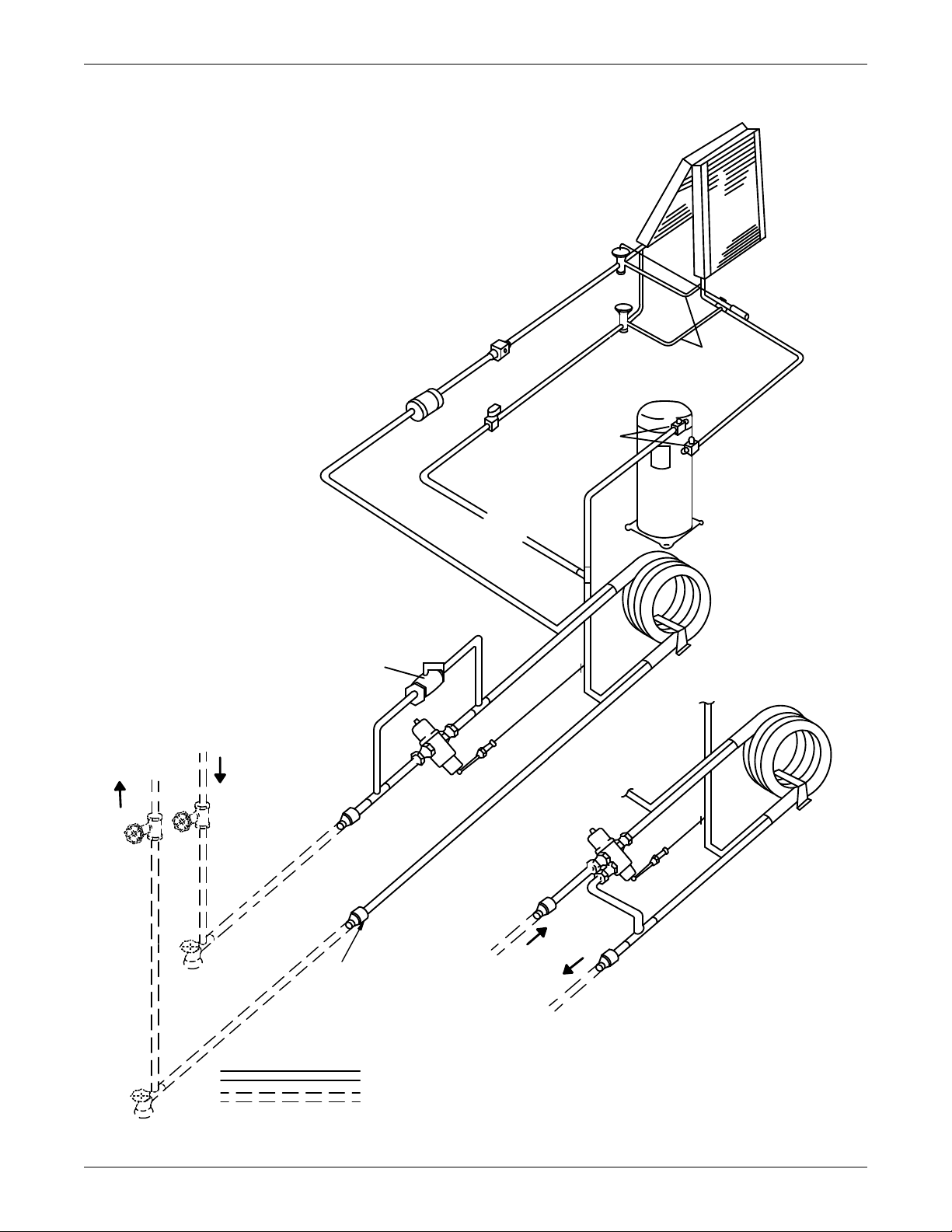
Water-Cooled Models—Self-Contained Compressor
Field-Supplied
Reducers
Required
on 3-Ton Units
DPN000359
REV 02
Evaporator
Coil
Expansion
Valve
Sensing
Bulb
External
Equalizers
Scroll
Compressor
Service
Valves
Hot Gas
Bypass
Solenoid
Val v e
Hot Gas
Bypass
Val v e
Sight
Glass
Filter
Dryer
Hot Gas
Bypass
Tube
in Tube
Condenser
Tube
in Tube
Condenser
Bypass
Valve
2-Way Water
Regulating
Val v e
3-Way Water
Regulating Valve
(optional)
Fluid
Return
From
Unit
Fluid
Supply
To
Unit
Fluid
Return
From
Unit
Fluid
Supply
To
Unit
Shutoff*
Valves
Hose Bibs*
FACTORY PIPING
FIELD PIPING
* Components are not supplied
by Liebert but are recommended
for proper circuit operation
and maintenance.
Figure 19 General arrangement—Water-cooled models with scroll compressor
36
Page 43
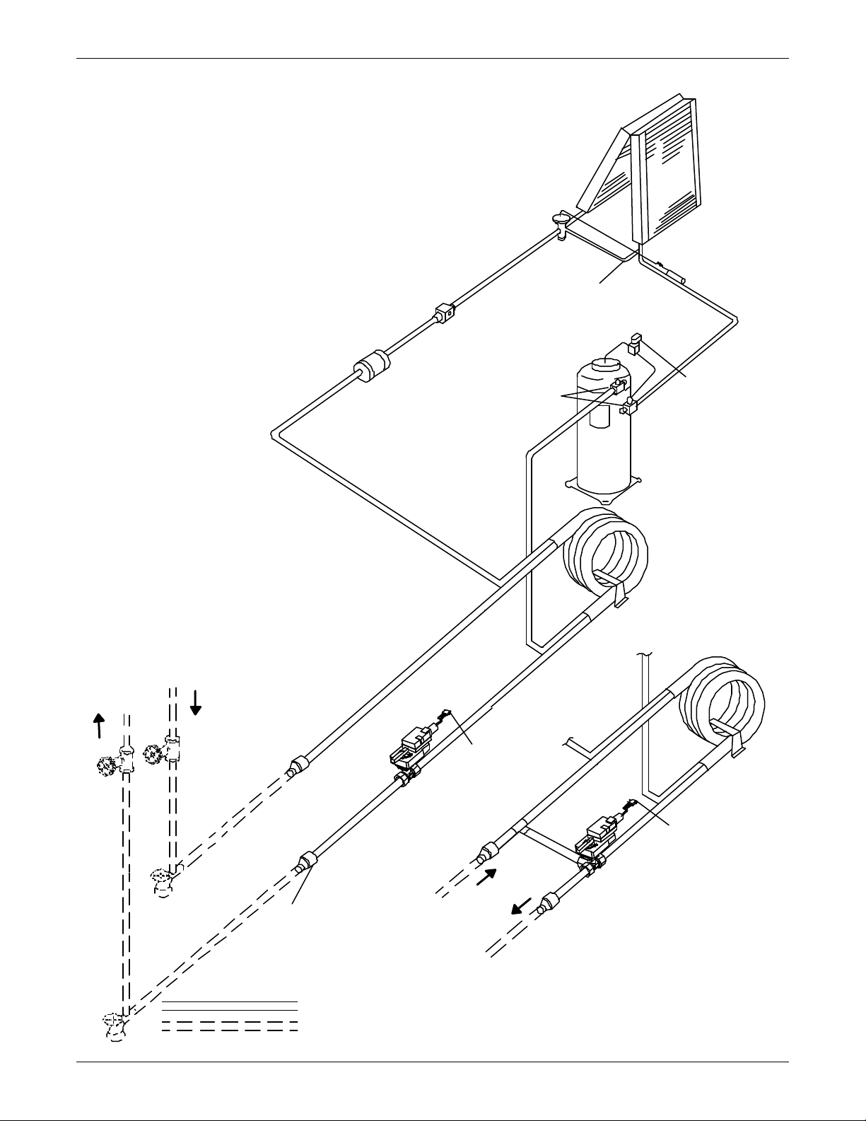
Water-Cooled Models—Self-Contained Compressor
DPN001727
Rev. 0
Evaporator
Coil
Expansion
Valve
Sensing
Bulb
External
Equalizer
Service
Va l v e s
Sight
Glass
Filter
Dryer
Tube
in Tube
Condenser
Tube
in Tube
Condenser
Fluid
Return
From
Unit
Fluid
Supply
To
Unit
Fluid
Return
From Unit
Fluid
Supply
To U nit
Shutoff*
Valv es
Hose Bibs*
FACTORY PIPING
FIELD PIPING
Digital
Compressor
Digital
Solenoid
Valv e
To Liebert
iCOM C ontrol
To Liebert
iCOM C ontrol
3-Way
Motorized
Ball Valve
(optional)
2-Way
Motorized
Ball Valve
*Components are not supplied
by Liebert but are recommended
for proper circuit operation
and maintenance.
Field-Supplied
Reducers
Required
on 3- Ton Units
Figure 20 General arrangement diagram—Water-cooled models with digital scroll
37
Page 44
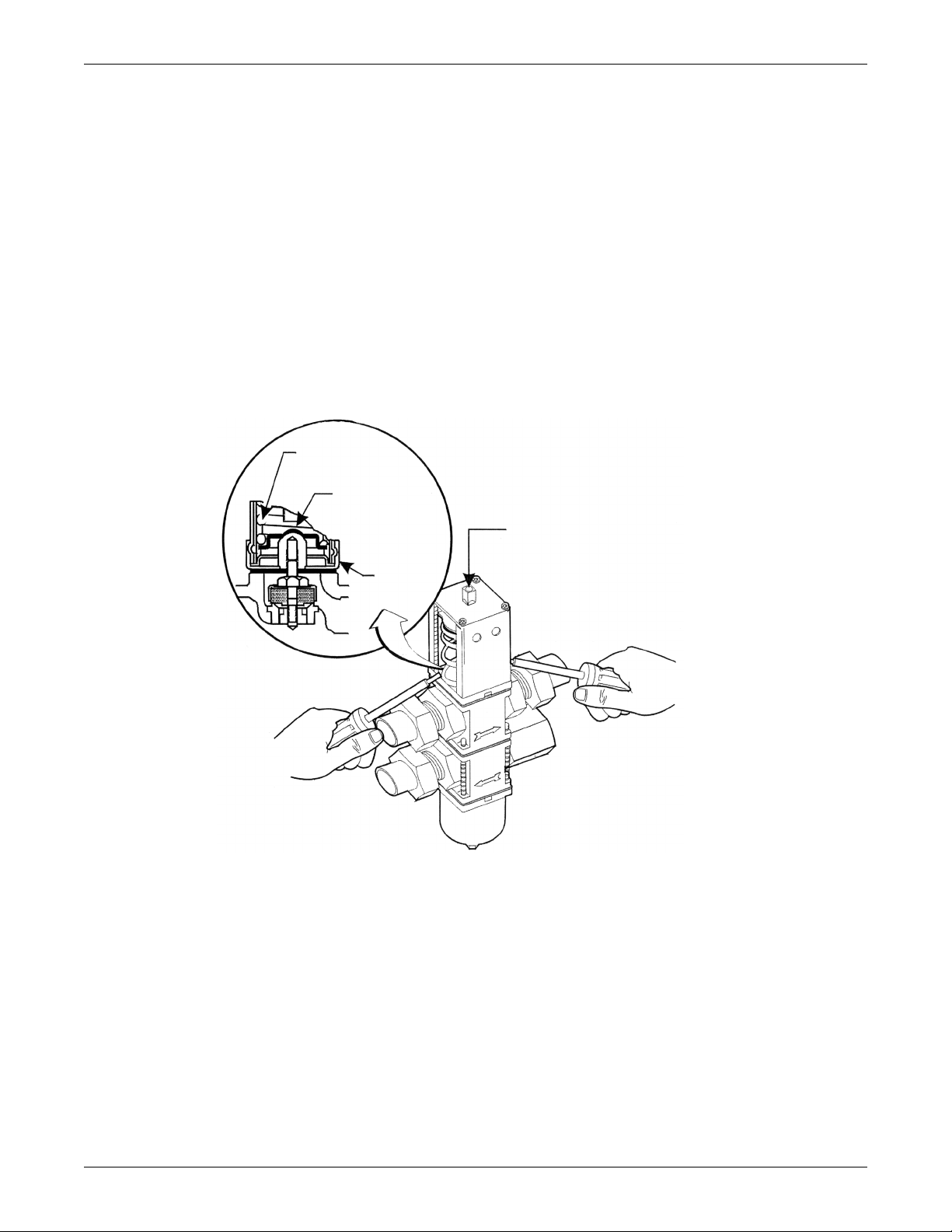
Water-Cooled Models—Self-Contained Compressor
Range
spring
Valve spring
guide
Top
retainer
Range adjustment screw
Insert screwdrivers underneath
the valve spring guide
4.3 Water Regulating Valve
The water regulating valve automatically regulates the amount of fluid necessary to remove the heat
from the refrigeration system, permitting more fluid to flow when load conditions are high and less
fluid to flow when load conditions are low. The valve consists of a brass body, balance spring, valve
seat, valve disc holders, capillary tube to discharge pressure, and adjusting screw.
4.3.1 Standard Valve - 150psig (1034kPa) System for 3 & 5-Ton Units (Johnson Controls Valve) High Pressure Valve - 350psig (2413kPa) System for 5-Ton Units (Johnson Controls Valve)
Adjustment
The valve may be adjusted with a standard refrigeration service valve wrench or screw driver.
To lower the head pressure setting, turn the square adjusting screw clockwise until the high pressure
gauge indicates the desired setting.
To raise the head pressure setting, turn the adjusting screw counterclockwise until the desired setting is obtained.
Figure 21 Johnson Controls valve adjustment
4.3.2 High Pressure Valve - 350 psig (2413 kPa) System for 3-Ton Units (Metrex Valve)
Adjustment
The valve may be adjusted using a 1/8" diameter rod. Turn the adjusting collar nut counterclockwise
to raise head pressure; turn it clockwise to lower head pressure. Rotation directions are viewed from
top of valve spring housing.
38
Page 45
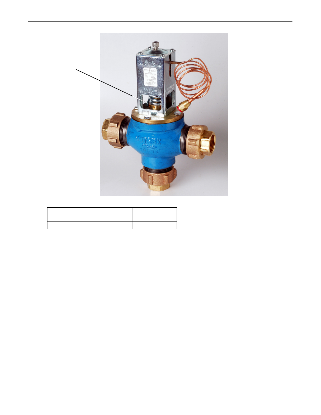
Figure 22 Metrex Valve adjustment
Adjusting collar nut
Water-Cooled Models—Self-Contained Compressor
4.4 Motorized Ball Valve—Digital Scroll Compressors
4.4.1 Control
Table 12 Refrigerant control settings psi (kPa)
Low Pressure
Cut Out
20 (137.9) 65 (448.2) 400 (2758)
Low Pressure
Cut In
High Pressure
Cut Out
Manual Flushing
The valve may be flushed by rotating the socket head screw clockwise. This screw must be in the OUT
position (counterclockwise) for normal valve operation.
On digital scroll units, discharge pressure is controlled by a motorized ball valve. During unloaded
operation, the pressure changes during each digital cycle could cause excessive repositions with a
pressure-operated water regulating valve. The control algorithm for the motorized ball valve uses an
intelligent sampling rate and adjustable pressure thresholds to reduce valve repositions. The valve
assembly consists of the brass valve, linkage and actuator.
The valve actuator operates on 24VAC power and is controlled by a 2-10VDC proportional control signal. The valve will move from fully open to fully closed in 60 seconds. At 2VDC, the valve is closed; at
10VDC, the valve is fully open. There is a 20-second delay to position the motorized ball valve before
starting the compressor.
Control Method
The control utilizes an upper and lower pressure threshold with a 35psi (241kPa) deadband to reduce
valve movement. If the liquid pressure is between the upper and lower threshold, the valve remains
at the current position. If the liquid pressure exceeds the upper threshold the valve opens, and if the
pressure falls below the lower threshold the valve closes. There are multiple adjustment bands to ease
discharge pressure back into control range.
39
Page 46

4.4.2 Adjustment
Both pressure thresholds can be shifted simultaneously over a 50psi (345kPa) range (the 35psi
[241kPa] differential remains constant). The ball valve setpoint offset parameter in the Liebert iCOM
Service menu can be adjusted from 0 to 50 PSI (345 kPa) to raise or lower the control band similar to
the pressure adjustment on a water regulating valve. Changing the setpoint offset will adjust the
pressure thresholds for both circuits. Units are factory-set at a 30psi (207 kPa) setpoint offset (30psi
[207 kPa] above minimum). This results in a 220psiA (1517kPa) lower threshold and a 255psiA
(1758kPa) upper threshold pressure.
4.4.3 Startup
The setpoint offset is adjusted to the minimum value during startup, then changes to the set value
once the compressor reaches normal operating pressures. Changes in fluid temperature could cause
pressure changes that do not result in valve movement within the deadband. Fan cycling stats should
be set to prevent continuous fluid temperature swings greater than 10
4.4.4 Location
The motorized ball valve is located in the condenser fluid return line. Three-way valves are piped in a
mixing arrangement with the common port at the valve outlet.
4.4.5 Manual Control
The valve can be manually set by disconnecting AC power, depressing the manual override button on
the valve actuator and adjusting the valve position with the handle. The motorized ball also can be
controlled through the Liebert iCOM’s Service menu using manual mode to override the normal control.
Water-Cooled Models—Self-Contained Compressor
°F (5.6°C).
40
Page 47
Glycol/GLYCOOL-Cooled Models—Self-Contained Compressor
!
5.0 GLYCOL/GLYCOOL-COOLED MODELS—SELF-CONTAINED COMPRESSOR
5.1 Drycooler Location
The drycooler should be located for maximum security and maintenance accessibility. Avoid groundlevel sites with public access or areas which contribute to heavy snow or ice accumulations. To assure
adequate air supply, it is recommended that drycoolers be located in a clean air area, away from loose
dirt and foreign matter that may clog the coil. In addition, drycoolers should not be located in the
vicinity of steam, hot air or fume exhausts. Also, drycoolers should not be located closer than 3 feet
(1 meter) from a wall, obstruction or adjacent unit.
5.2 Drycooler Installation
For roof installation, mount drycoolers on steel supports in accordance with local codes. To minimize
sound and vibration transmission, mount steel supports across load bearing walls. For ground installation, a concrete pad will provide adequate support. Drycooler legs have mounting holes for securing
the drycooler to steel supports or concrete pad.
5.3 Electrical Connections
Refer to equipment nameplate regarding wire size and circuit protection requirements. Refer to electrical schematic when making connections. Make all wiring and electrical connections in accordance
with local and national codes.
WARNING
Risk of electric shock. Can cause injury or death.
Potentially lethal voltages exist within this equipment during operation. Observe all cautions
and warnings on unit and in this manual.
The Liebert iCOM microprocessor does not isolate power from the unit, even in the “Unit Off”
mode. The only way to ensure that there is NO voltage inside the unit is to install and open a
remote disconnect switch. Refer to unit electrical schematic.
Use voltmeter to make sure power is turned off before making any electrical connections.
5.3.1 Line Voltage
Line voltage electrical service is required for all drycoolers at the location of the drycooler. This power
supply does not have to be the same voltage as the indoor unit. This separate power source may be
208, 230, 460, or 575 V, 60 Hz; or 200, 230, or 380/415 V, 50 Hz. The disconnect switch is factory-supplied and mounted in the electric panel.
5.3.2 Low Voltage
A control interlock between the drycooler and the indoor unit is required and is connected between 70
and 71 in the handy box of the indoor unit and the pump and drycooler control box of the drycooler.
NEC Class 1 wiring is required.
5.3.3 Pump and Drycooler
All wiring to the pump and drycooler from the control box should be done in accordance with the electrical schematic on the inside lid of the drycooler control box and with local and national codes.
41
Page 48
5.4 Glycol Piping
!
!
!
These guidelines apply to the field leak checking and fluid requirements for field piping systems.
General Guidelines
• Equipment damage and personal injury can result from improper piping installation, leak checking, fluid chemistry and fluid maintenance.
• Follow local piping codes, safety codes.
• Qualified personnel must install and inspect system piping.
• Contact a local water consultant regarding water quality, corrosion protection and freeze protection requirements.
• Install manual shutoff valves at the supply and return line to each indoor unit and drycooler to
permit routine service and emergency isolation of the unit.
CAUTION
Risk of frozen fluids. Can cause equipment damage and building damage.
Freezing system fluids can rupture piping. Complete system drain-down cannot be ensured.
When the field piping or unit may be exposed to freezing temperatures, charge the system
with the proper percentage of glycol and water for the coldest design ambient.
Automotive antifreeze is unacceptable and must NOT be used in any glycol fluid system.
CAUTION
Risk of corrosion. Can cause equipment damage.
Read and follow individual unit installation instructions for precautions regarding fluid
system design, material selection and use of field-provided devices. Liebert systems contain
iron and copper alloys that require appropriate corrosion protection.
Contact a local water consultant regarding water quality, corrosion and freeze protection
requirements.
Water chemistry varies greatly by location, as do the required additives, called inhibitors,
that reduce the corrosive effect of the fluids on the piping systems and components. The
chemistry of the water used must be considered, because water from some sources may
contain corrosive elements that reduce the effectiveness of the inhibited formulation.
Preferably, surface waters that are classified as soft and are low in chloride and sulfate ion
content should be employed. Proper inhibitor maintenance must be performed in order to
prevent corrosion of the system. Consult glycol manufacturer for testing and maintenance of
inhibitors.
Commercial ethylene glycol (Union Carbide Ucartherm, Dow Chemical Dowtherm SR-1 and
Texaco E.G. Heat Transfer Fluid 100), when pure, is generally less corrosive to the common
metals of construction than water itself. It will, however, assume the corrosivity of the water from
which it is prepared and may become increasingly corrosive with use if not properly inhibited.
Glycol/GLYCOOL-Cooled Models—Self-Contained Compressor
CAUTION
Risk of oxide layer formation. Can cause equipment damage.
Idle fluid allows the collection of sediment that prevents the formation of a protective oxide
layer on the inside of tubes. Keep unit switched ON and system pump operating.
42
Page 49
Glycol/GLYCOOL-Cooled Models—Self-Contained Compressor
NOTICE
Risk of debris or precipitate clogging pipes. Can cause equipment damage.
Galvanized pipe must not be used in or with systems or units that contain glycol. The
phosphates in the inhibitor can react with the zinc in the galvanized pipe, precipitating an
insoluble material that can eventually foul the system.
Fluid-cooled condensers have small internal flow passages. To avoid clogging and other
resulting system operation problems, install a 16-20 mesh filter in the fluid supply line to the
indoor unit. The filter should be located where it can be easily serviced or replaced.
Do not install unit on open loop systems. Debris carried by the fluid will clog the brazed plate
condenser.
NOTICE
Risk of improper installation. Can cause equipment or structural damage.
Supply and return lines must be supported in a way that keeps their weight from bearing on
the piping of the unit, drycooler or pumps. Failure to support piping can strain the
equipment’s structural integrity.
A relief valve must be installed in the system to avoid the possibility of burst pipes. This valve
may be obtained from the supplier as an option or obtained from another vendor.
Emerson recommends installing manual service shut-off valves at the supply and return connections
to each unit. This enables routine service and/or emergency isolation of the unit. In addition, multiple
pump packages require a check valve at the discharge of each pump to prevent back flow through the
standby pump(s).
To facilitate filling, installation of hose bibs at the lowest point of the system is recommended.
Consideration of the minimum glycol temperature to be supplied from the drycooler will determine if
the need exists to insulate the glycol supply and return lines. Insulation will prevent condensation on
the glycol lines in low ambient conditions.
All fluid piping must comply with local codes. Care in sizing pipes will help reduce pumping power
and operating costs.
Table 13 Room dew point temperatures
Dry Bulb
°F (°C)
70 (21.1)
70 (21.1)
72 (22.2)
72 (22.2)
75 (23.8)
75 (23.8)
* Minimum glycol temperature before condensation will occur.
Wet Bulb
°F (°C)
57.2 (14.0)
58.5 (14.7)
58.9 (24.9)
60.0 (15.5)
61.2 (16.2)
62.5 (16.9)
Relative
Humidity
45
50
45
50
45
50
Dew Point*
°F (°C)
48.0 (8.9)
50.5 (10.3)
50.0 (10.0)
52.4 (11.3)
52.4 (11.3)
55.0 (12.7)
43
Page 50
Glycol/GLYCOOL-Cooled Models—Self-Contained Compressor
5.4.1 Expansion Tanks, Fluid Relief Valves and Other Devices
An expansion tank must be provided for expansion and contraction of the fluid due to temperature
change in this closed system. Vents are required at system high points to vent trapped air when filling the system. A relief valve is a also a necessary piping component.
Depending on the complexity of the system, various other devices may be specified. Pressure gauges,
flow switches, automatic air separator, tempering valves, standby pumps, sensors for electrical controls, and flow switches are just a few of these devices.
NOTICE
Risk of freezing temperatures. Can cause equipment and piping damage.
Immediately following the use of water for leak testing or system cleaning, charge the tested
system with the proper percentage of glycol and water for your coldest design ambient.
Complete system drain-down cannot be assured and damage to the system could result from
freezing of residual water.
5.5 Filling Instructions
5.5.1 Preparing the System for Filling
It is important to remove any dirt, oil or metal filings that may contaminate the cooling system piping
in order to prevent contamination of the fresh glycol solution and fouling of the drycooler piping. The
system should be flushed thoroughly using a mild cleaning solution or high-quality water and then
completely drained before charging with glycol. Cleaning new systems is just as important as cleaning old ones. New systems can be coated with oil or a protective film; dirt and scale are also common.
Any residual contaminants could adversely affect the heat transfer stability and performance of your
system. In many cases, in both old and new systems, special cleaners are needed to remove scale, rust
and hydrocarbon foulants from pipes, manifolds and passages. Clean heat transfer surfaces are
important in maintaining the integrity of the heating/cooling system. For more information on cleaners and degreasers, contact your sales representative. Follow the manufacturer's instructions when
using these products.
Calculate the internal volume of the system as closely as possible. See Table 14 and Table 16 for
unit volumes. Use volume in Table 15 for glycol piping volumes.
Table 14 Indoor unit glycol volume approximate gallons (liters) max.
Model (50 Hz) Glycol-Cooled GLYCOOL
046WG/(045WG) 1.2 (4.5) —
071WG/(070WG) 2.0 (7.5) —
061G/(058G) — 4.0 (15.1)
Table 15 Volume in standard Type “L” copper piping
Diameter (in.) Volume
Outside Inside Gal/Ft L/M
1/2 0.123 0.008 0.01
5/8 0.555 0.012 0.15
3/4 0.666 0.018 0.22
7/8 0.785 0.025 0.31
1-1/8 1.025 0.043 0.53
44
Page 51

5.5.2 Glycol Solutions
NOTE
Glycol solutions should be considered for protection of the coil. When it is not used, damage can
occur from either freezing or corrosion from water.
When considering the use of any glycol products in a particular application, you should review the latest Material Safety Data Sheets and ensure that the use you intend can be accomplished safely. For
Material Safety Data Sheets and other product safety information, contact the supplier nearest you.
Before handling any other products mentioned in the text, you should obtain available product safety
information and take necessary steps to ensure safety of use.
NOTICE
Risk of improper handling of glycol. Can cause environmental damage and violate national,
regional and local laws.
When mishandled, glycol products pose a threat to the environment. Before using any glycol
products, review the latest Material Safety Data Sheets and ensure that you can use the
product safely.
Glycol manufacturers request that the customer read, understand and comply with the
information on the product packaging and in the current Material Safety Data Sheets. Make
this information available to anyone responsible for operation, maintenance and repair of the
drycooler and related equipment.
No chemical should be used as or in a food, drug, medical device, or cosmetic, or in a product or process in which it may contact a food, drug, medical device, or cosmetic until the user has determined
the suitability and legality of the use. Since government regulations and use conditions are subject to
change, it is the user's responsibility to determine that this information is appropriate and suitable
under current, applicable laws and regulations.
Glycol/GLYCOOL-Cooled Models—Self-Contained Compressor
NOTICE
Risk of using improper cooling agent. Can cause reduced cooling performance and damage to
equipment and piping.
Proper formulations of inhibited formula ethylene glycol and propylene glycol must be used in
the Challenger 3000 system. Automotive antifreeze is unacceptable and must NOT be used.
Typical inhibited formula ethylene glycol and propylene glycol manufacturers and suppliers are
Union Carbide (Ucartherm) or Dow Chemical (Dowtherm SR-1, Dowfrost). These glycols are supplied
with corrosion inhibitors and do not contain a silicone anti-leak formula. Commercial ethylene glycol,
when pure, is generally less corrosive to the common metals of construction than water itself. Aqueous solutions of these glycols, however, assume the corrosivity of the water from which they are prepared and may become increasingly corrosive with use if not properly inhibited.
There are two basic types of additives: corrosion inhibitors and environmental stabilizers. The corrosion inhibitors function by forming a surface barrier that protects the metals from attack. Environmental stabilizers, while not corrosion inhibitors in the strictest sense of the word, decrease corrosion
by stabilizing or favorably altering the overall environment. An alkaline buffer such as borax is a simple example of an environmental stabilizer since its prime purpose is to maintain an alkaline condition (pH above 7).
The percentage of glycol to water must be determined by using the lowest design outdoor temperature
in which the system is operating. Table 16 indicates the solution freeze point at several concentration levels of ethylene glycol. Propylene glycol concentrations should be 1% higher than the ethylene
glycol table values to find the freeze point. For example, 41% propylene glycol freezes at -10°F.
45
Page 52
Table 16 Ethylene glycol concentrations
% Glycol by Volume 0 * 10 20 30 40 50
Freezing Point °F (°C) 32 (0) 25 (-3.9) 16 (-8.9) 5 (-15.0) -10 (-23.3) -32 (-35.5)
Apparent Specific Gravity
@ 50°F (10°C)
* A minimal amount of glycol should be considered for inhibitive coil protection.
NOTICE
Risk of corrosion from water impurities. Can cause equipment damage.
The quality of water used for dilution must be considered because water may contain
corrosive elements which reduce the effectiveness of the inhibited formulation. Water that is
classified as soft (low in chloride and sulfate ion content less than 100 parts per million each)
should be used.
5.5.3 Filling the System
Installation of hose bibs at the lowest point of the system is recommended. When filling a glycol system keep air to a minimum. Air in glycol turns to foam and is difficult and time-consuming to remove.
(Anti-foam additives are available and may be considered.) Open all operating systems to the loop.
With the top vent(s) open, fill the system from the bottom of the loop. This will allow the glycol to
push the air out of the top of the system, minimizing trapped air. Fill to approximately 80% of calculated capacity. Fill slowly from this point, checking fluid levels until full.
Glycol/GLYCOOL-Cooled Models—Self-Contained Compressor
1 1.014 1.028 1.042 1.057 1.071
NOTE
For glycol solution preparation and periodic testing, follow manufacturer's recommendations.
Do not mix products of different manufacturers.
46
Page 53
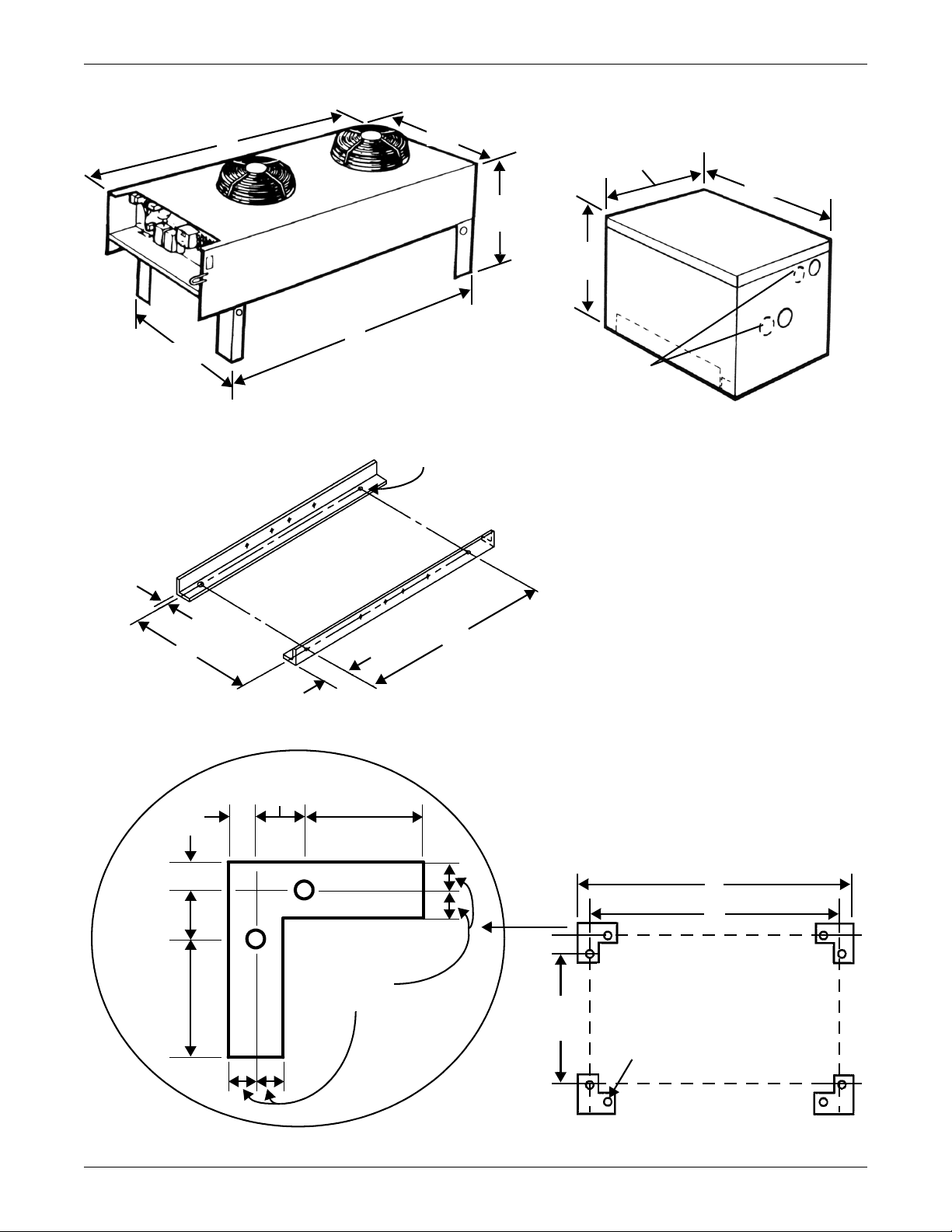
Figure 23 Drycoolers and pump packages
Notes
1. Single pump packages are 17-1/4"
(438 mm) wide. Dual pump packages ar
32-1/4" (819 mm) wide.
2. Mounting holes are 15-1/4" (387 mm)
apart on single pump packages and 301/4" (768 mm) apart on dual pump
packages.
3. Connection sizes apply to primary pump
supplier.
DRYCOOLER
Provided on
dual pump
package only
30-1/4"
(768mm)
A
B
19"
(483mm)
43-3/16"
(1097mm)
43-9/16"
(1105mm)
37-7/8"
(1095mm)
GLYCOL PUMP PACKAGE
See Note 1
A
B
C
3/4"
(19mm)
37-11/16"
(957mm)
1/2" (12.7mm) diameter
anchor bolts (typ)
B
C
PUMP PACKAGE
MOUNTING ANGLES
TYPICAL
FOOTPRINT
UNIT ANCHOR PLAN
See Table 18 for keys to
dimensions “A”, “B” and “C”.
See Table 17 for keys to
dimensions “A”, “B” and “C”.
1/2" diameter holes
for mounting (4 typ)
Note: Angles located
inside, bottom of pump
package. View used for
mounting reference.
1"
(25.4mm)
1"
(25.4mm)
1-3/4"
(25.4mm)
1-3/4"
(25.4mm)
4-1/4"
(25.4mm)
4-1/4"
(25.4mm)
For expansion tank dimensions,
see Figure 24 on page -48.
Glycol/GLYCOOL-Cooled Models—Self-Contained Compressor
47
Page 54
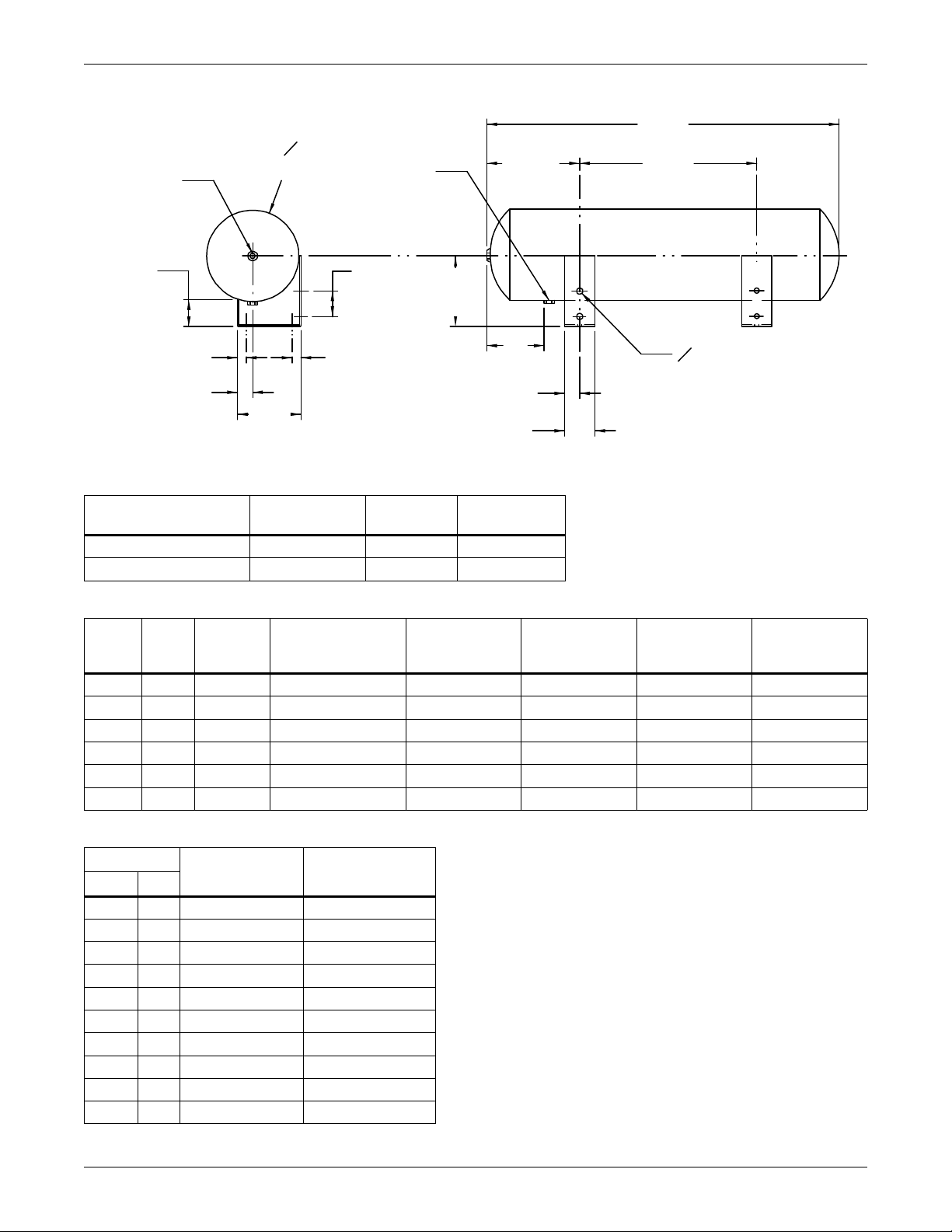
Glycol/GLYCOOL-Cooled Models—Self-Contained Compressor
1/2" FPT
Fitting
1/2" FPT
Fitting
6-13/16"
(173mm)
17-1/4"
(438.2mm)
30-1/2
(774.7mm)
4"
(101.6mm)
2-3/4"
(69.9mm)
SL-10065 Pg. 7B
SL-10070 Pg. 6B
O 9"
(228.6mm)
O 1/2" (12.7mm) 8 holes
EXPANSION TANK
8.8 gal. (33.3L)
1-1/2"
(38.1mm)
1-1/2" (38.1mm)
1" (25.4mm)
1"
(25.4mm)
6-1/8"
(155.6mm)
7"
(177.8mm)
3"
(76.2mm)
2-1/2"
(63.5mm)
Figure 24 Pump packages—expansion tank
Table 17 Mounting hole dimensional data
A
PUMP PACKAGE
SINGLE (0.75 - 7.5 Hp) 15-1/4 (387.4) 2-1/2 (63.5) 22-1/2 (571.5)
DUAL (0.75 - 5 Hp) 30-1/4 (768.4) 2-1/2 (63.5) 22-1/2 (571.5)
in (mm)
B
in (mm)
C
in (mm)
Table 18 Drycooler data
Drycooler
Model
-069 1 410 (186) 1-1/4 51-1/2 (1308) 44 (1118) 42 (1067) 2.4 (9.2)
-092 1 430 (195) 1-1/2 51-1/2 (1308) 44 (1118) 42 (1067) 3.7 (13.9)
-109 1 450 (204) 2 51-1/2 (1308) 44 (1118) 42 (1067) 4.9 (18.6)
-112 1 470 (213) 2 51-1/2 (1308) 44 (1118) 42 (1067) 5.8 (22.0)
-139 2 565 (256) 2 91-1/2 (2324) 84 (2134) 82 (2083) 4.8 (18.2)
-197 2 605 (274) 2 91-1/2 (2324) 84 (2134) 82 (2083) 9.0 (34.1)
No.
No. of
Fans
Weight
lb (kg)
Conn. Sizes
(Suct. & Disc.) in.
“A” Dimension
in. (mm)
“B” Dimension
in. (mm)
“C” Dimension
in. (mm)
Table 19 Glycol pump data*
Pump
3/4 60 1-1/4 3/4
1-1/2 60 1-1/4 3/4
260 1-1/4 3/4
360 1-1/2 1
5 60 1-1/2 1-1/4
3/4 50 1-1/4 3/4
150 1-1/4 3/4
1-1/2 50 1-1/4 3/4
250 1-1/4 3/4
3 50 1-1/2 1-1/4
* Connection sizes apply to primary pump supplier
Pump Suction
Connection in.
Pump Discharge
Connection in. Hp Hz
48
Coil Internal
Volume gal. (l)
Page 55
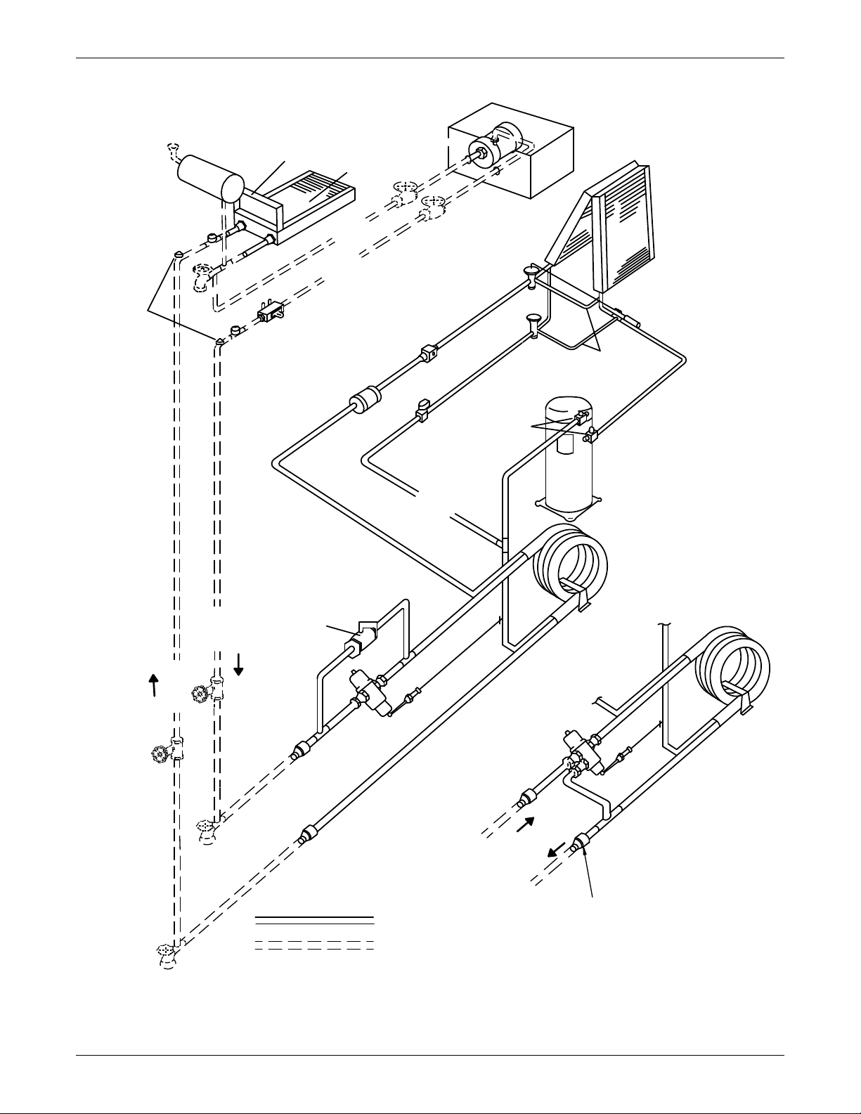
Glycol/GLYCOOL-Cooled Models—Self-Contained Compressor
Glycol
Pump
Pump
Housing
Unions*
Isolation
Valves*
Expansion
Val ve
Drycooler
Electric Box
Drycooler
Coil
Fluid
Return
to Pump
Fluid
Supply
from
Pump
Unions*
Field-Supplied
Reducers Required
on 3-Ton Units
Fill*
Expansion Tank Field-Installed at
Highest Point in System
Expansion
Port*
Hose
Bibs*
Flow Regulating
Val ve*
Pressure
Port*
Sight
Glass
Filter
Dryer
Evaporator
Coil
Sensing
Bulb
External
Equalizers
Hot Gas
Bypass
Valve
Scroll
Compressor
Service
Valves
Hot Gas
Bypass
Solenoid
Valve
Hot Gas
Bypass
Tube
in Tube
Condenser
Tube
in Tube
Condenser
Bypass
Val ve
2-Way Water
Regulating
Valve
Fluid
Return
from
Unit
Fluid
Supply
to Unit
Fluid
Return
from
Unit
Fluid
Supply
to Unit
Isolation
Valves*
Hose
Bibs*
3-Way Water
Regulating Valve
(optional)
FACTORY PIPING
FIELD PIPING
*Components are not
supplied by Liebert but
are recommended for
proper circuit operation
and maintenance
DPN000361
Rev. 02
Figure 25 General arrangement—Glycol-cooled models with scroll compressor
49
Page 56
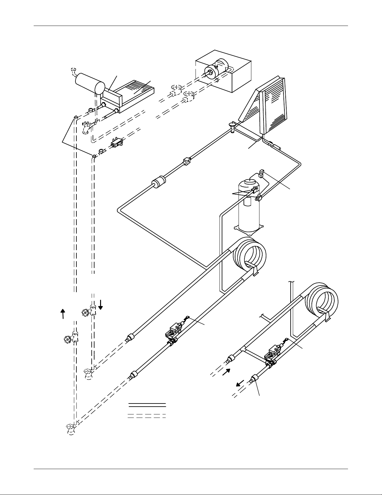
Glycol/GLYCOOL-Cooled Models—Self-Contained Compressor
Digital
Solenoid
Valve
Glycol
Pump
Housing
Unions*
Isolation
Valves*
Expansion
Valve
Drycooler
Electric
Box
Drycooler
Coil
Fluid
Return
to Pump
Fluid Supply
from Pump
Unions*
Fill*
Expansion Tank Field-Installed at
Highest Point in System.
Expansion
Port*
Air Vents*
at Top of
Risers
Flow Regulating
Valve*
Pressure
Port*
Sight
Glass
Filter
Dryer
Evaporator
Coil
Sensing
Bulb
External
Equalizer
Digital
Compressor
Service
Valves
Tube
in Tube
Condenser
Tube
in Tube
Condenser
2-Way
Motorized
Ball Valve
Fluid
Return
from
Unit
Fluid
Supply
to Unit
Isolation
Val ves*
Hose
Bibs*
Hose
Bibs*
Hose
Bibs*
Fluid
Supply
to Unit
Fluid
Return
From
Unit
3-Way
Motorized
Ball Valve
(optional)
FACTORY PIPING
*Components are not supplied by Liebert but
are recommended for proper circuit operation
and maintenance.
FIELD PIPING
DPN001722
Rev. 0
Field-Supplied
Reducers
Required on 3
Ton Units
To i C OM C o n t ro l
To i C O M C o n tr o l
Pump
Figure 26 General arrangement—Glycol-cooled models with digital scroll
50
Page 57
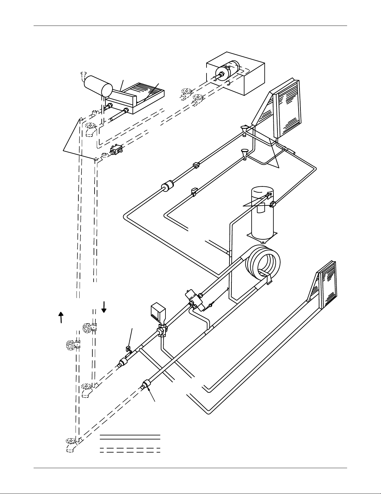
Glycol/GLYCOOL-Cooled Models—Self-Contained Compressor
Field-Supplied
Reducers
Required on 3-Ton Units
Pump
Housing
Pump
Unions*
Unions*
Isolation
Valves*
Expansion
Valve
Evaporator
Coil
Drycooler
Coil
Drycooler
Electric Box
Pressure
Port*
Pressure
Port*
Hose
Bib*
Fill*
Fluid
Return to
Pump
Fluid
Supply
from Pump
Air Vents*
at Top of
Risers
Flow Regulating
Valve*
Sight
Glass
Sensing
Bulb
External
Equalizers
Hot Gas
Bypass
Valve
Scroll
Compressor
Service
Valves
Filter
Dryer
Hot Gas
Bypass
Econ-O-Coil
3-Way Water
Regulating
Valve
3-Way Chilled
Glycol Valve
Valve
Actuator
Econ-O-Cycle
Comparator
Econ-O-Coil
Circuit
Tube
in Tube
Condenser
Fluid
Supply to
Unit
Fluid
Return
from
Unit
Isolation
Valves*
Hose
Bibs*
FACTORY PIPING
FIELD PIPING
*Components are not supplied
by Liebert but are recommended
for proper circuit operation
and maintenance.
Expansion Tank Field-Installed at
Highest Point in System
DPN000379
Rev. 03
Glycol
Figure 27 General arrangement—GLYCOOL models with scroll compressor
51
Page 58
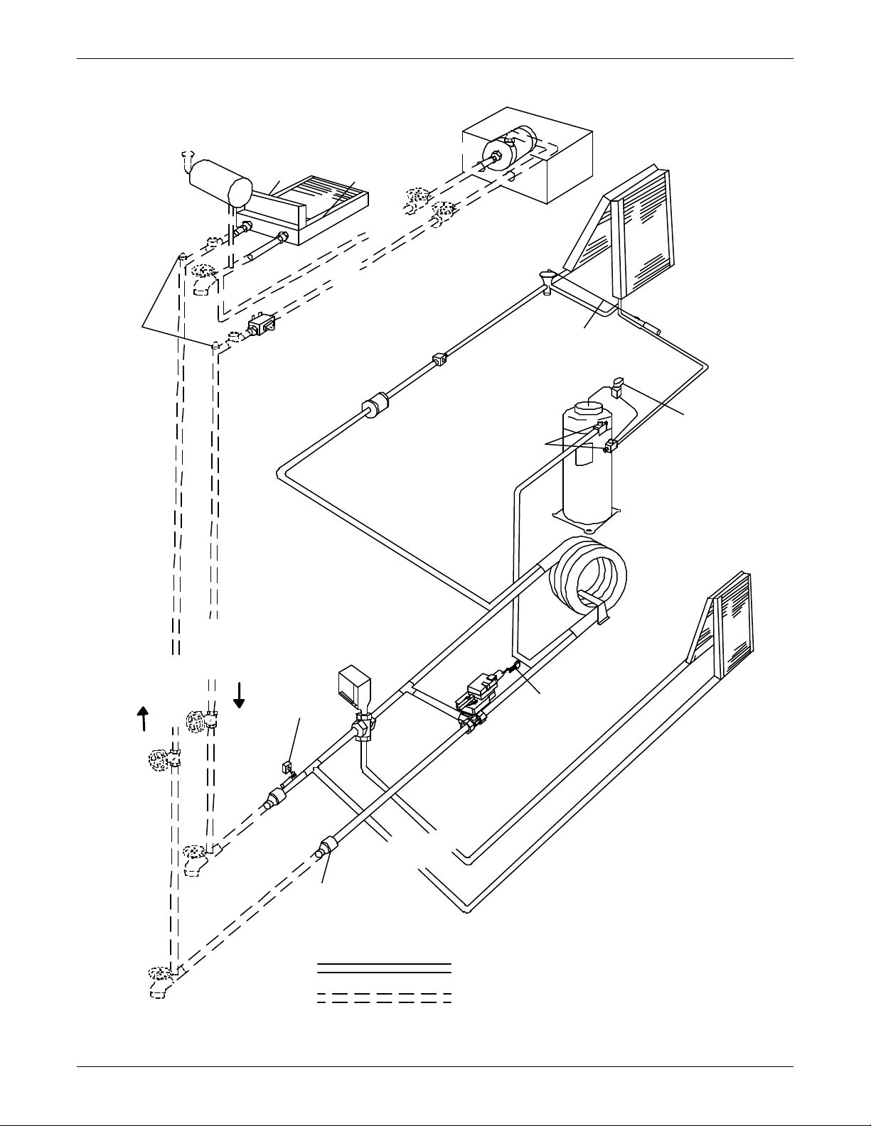
Glycol/GLYCOOL-Cooled Models—Self-Contained Compressor
r
Digital
Solenoid
Val v e
Pu m p
Housing
Gl ycol
Pu m p
Unions*
Isolation
Val v e s*
Ex p an si on
Val v e
Ev a p o r a t o r
Co i l
Drycooler
Coi l
Drycooler
El e c t r i c
Bo x
Unions*
Pre ssu re
Po r t *
Hose
Bi b *
Fill*
Fl u id
Re t ur n t o
Pu m p
Fl u i d
Supply
from
Pu m p
Flow Regul at ing Valve*
Pr essu re
Po r t *
Si g h t
Gl a ss
Se n s i n g
Bu l b
Ex t e rn al
Eq ualizer
Se rv i c e
Val v es
Fi l t e r
Dryer
Econ-O-Coil
3-Way Chilled
Glycol Valve
3-Way Mot ori zed
Ba l l Va lv e
Val v e
Actu ator
Econ-O-Cycle
Comparator
Ec on - O- Co il
Ci rcui t
Tu b e
in Tu be
Cond enser
Flui d
Su p p l y t o
Unit
Fl u i d
Re t u r n
from
Uni t
Isolati on
Val v es*
Hose
Bib s*
FA CTORY PIPI N G
FIELD PI PI N G
*Components are not supplied b y Liebert but
are recommended for proper circuit o p eration
and mai n te nan ce.
Expansion Tank Field-Installed at
Highest Point in System
DPN001724
Re v. 0
Field-Supplied
Re d u c e r s
Required on 3-Ton Units
To iCOM Control
Digital
Co mp r esso r
Figure 28 General arrangement—GLYCOOL models with digital scroll compressor
52
Page 59
Glycol/GLYCOOL-Cooled Models—Self-Contained Compressor
5.5.4 Motor Ball Valve—Digital Scroll Compressors
Refer to 4.4 - Motorized Ball Valve—Digital Scroll Compressors for details on the motorized ball
valve.
5.6 Condenser
The condenser is designed to operate in conjunction with a drycooler. The maximum coolant pressure
is 350 psig (2413 kPa).
5.7 Glycol Regulating Valve
The glycol regulating valve automatically regulates the amount of coolant necessary to remove the
heat from the refrigeration system, permitting more fluid to flow when load conditions are high and
less fluid to flow when load conditions are low. The valve consists of a brass body, balance spring,
valve seat, valve disc holders, capillary tube to discharge pressure, and adjusting screw.
5.7.1 Standard Valve - 150psig (1034kPa) System for 3 & 5-Ton Units (Johnson Controls Valve) High Pressure Valve - 350psig (2413kPa) System for 5-Ton Units (Johnson Controls Valve)
For details, refer to 4.3.1 - Standard Valve - 150psig (1034kPa) System for 3 & 5-Ton Units
(Johnson Controls Valve) High Pressure Valve - 350psig (2413 kPa) System for 5-Ton Units
(Johnson Controls Valve).
5.7.2 High Pressure Valve - 350 psig (2413 kPa) System for 3-Ton Units (Metrex Valve)
For details, refer to 4.3.2 - High Pressure Valve - 350 psig (2413 kPa) System for 3-Ton Units
(Metrex Valve).
5.7.3 Testing Valve Function
When the refrigeration system has been off for approximately 10-15 minutes, the coolant flow should
stop.
Should the coolant continue to flow, the valve is either improperly adjusted (head pressure is too low)
or the pressure sensing capillary is not connected properly to the condenser.
Table 20 Refrigerant control settings psi (kPa)
Low Pressure
Cut Out
20 (137.9) 65 (448.2) 400 (2758)
Low Pressure
Cut In
High Pressure
Cut Out
53
Page 60
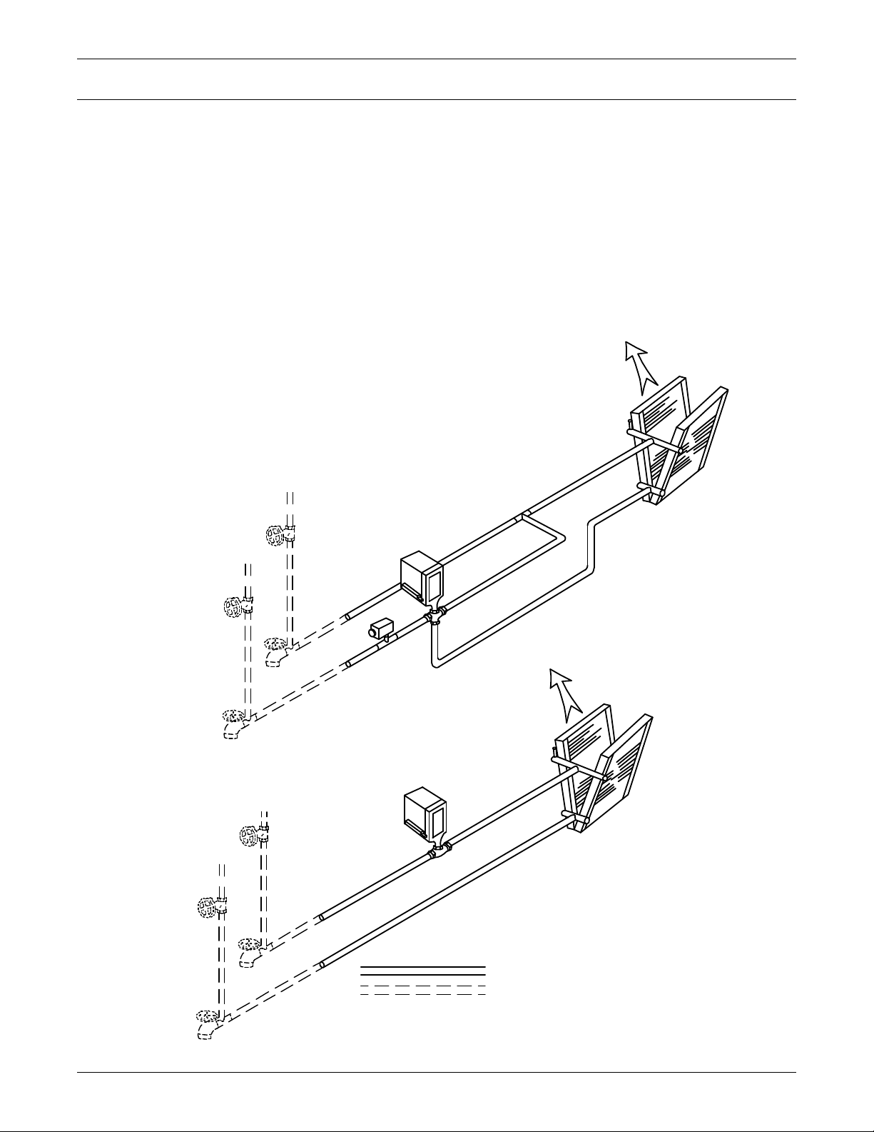
6.0 CHILLED WATER MODELS
A
B
AB
FACTORY PIPING
SL-11899
Pg. 5
Air
Flow
Air
Flow
Chilled
Water
Coil
Chilled
Water
Coil
Bleed
Val ve
Bleed
Val ve
Val ve
Actuator
Val ve
Actuator
Val ve
2-Way
Chilled
Water
Val ve
Flow
Switch
(optional)
Chilled
Water
Supply
Chilled
Water
Supply
Chilled
Water
Return
Chilled
Water
Return
Hose
Bibs *
Hose
Bibs *
Shutoff
Shutoff
Val v e s *
3-WAY VALVE
2-WAY VALVE
*Components are not supplied by Liebert but
are recommended for proper circuit operation
and maintenance.
FIELD PIPING
3-Way
Chilled
Water
6.1 Piping Considerations
Manual shut-off valves should be installed at the supply and return lines to each unit. This will provide for routine service and emergency isolation of the unit.
Consideration of the minimum water temperature to be supplied from the chiller will determine if the
need exists to insulate supply and return lines. Insulation will prevent condensation on the supply
and return lines.
To provide for the emergency of water leaks and the consequences of sub-floor flooding, floor drains
should be provided with wet traps or a water detection system, such as a Liebert Liqui-tect, that is
installed near the base of the unit or below the elevated floor.
Figure 29 Chilled water general arrangement - Upflow (BU)
Chilled Water Models
54
Page 61
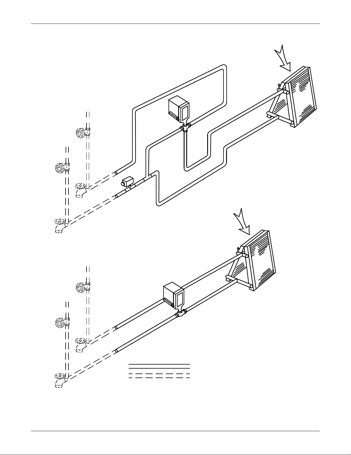
Figure 30 Chilled water general arrangement - Downflow (BF) models
SL-11899
Pg. 6
A
B
Flow
Switch
(optional)
Chilled
Water
Return
Chilled
Water
Supply
Chilled
Water
Return
Chilled
Water
Coil
Chilled
Water
Coil
2-Way Chilled
Water Valve
Chilled
Water
Supply
Hose
Bibs *
3-WAY VALVE
2-WAY VALVE
3-Way
Chilled
Water
Valve
Air
Flow
Air
Flow
Valve
Actuator
Valve
Actuator
AB
Bleed
Valve
Bleed
Valve
Hose
Bibs *
Shutoff
Valves *
*Components are not supplied by Liebert,
but are recommended for proper circuit
operation and maintenance.
FACTORY PIPING
FIELD PIPING
Chilled Water Models
55
Page 62
7.0 SPLIT SYSTEM MODELS
!
Three condensing unit styles are available: two air-cooled and one water/glycol-cooled condensing
unit.
7.1 Location Considerations
7.1.1 Air-Cooled Condensing Units
To assure an adequate air supply, it is recommended that all condensing units be located in a clean
air area, away from loose dirt and foreign matter that may clog the coil.
The outdoor condensing unit must not be located in the vicinity of steam, hot air, or fume exhausts or
closer than 18" from a wall, obstruction, or adjacent unit.
The outdoor condensing unit should be located for maximum security and maintenance accessibility.
Avoid ground-level sites with public access or areas that will contribute to heavy snow accumulations.
Do not allow the discharge air to blow into another condensing unit.
The outdoor condensing unit must be located at the same level or above the indoor Liebert Challenger
3000 unit. It must NOT be located below the indoor unit.
A solid base, capable of supporting the weight of the condenser and at least 2" (51 mm) higher than
the surrounding grade and at least 2" (51 mm) larger than the condensing unit base dimensions,
should be installed at the pre-determined location. In snow areas, a base of sufficient height to clear
snow accumulation must be installed.
Split System Models
The centrifugal fan air-cooled condensing unit may be located above the dropped ceiling or any remote
indoor area. If noise is of concern, the condensing unit should be located away from personnel. Normal
operating sound may be objectionable if the condensing unit is placed near quiet work areas.
To mount the unit in the ceiling, refer to 7.5.1 - Installing the Indoor Condensing Unit for hanging guidelines and to Figure 35 - Detail of ceiling hanging bracket for dimensional data.
7.1.2 Water/Glycol-Cooled Condensing Units
The condensing unit may be located above the dropped ceiling or any remote indoor area. If noise is of
concern, the condensing unit should be located away from personnel. Normal operating sound may be
objectionable if the condensing unit is placed near quiet work areas. To mount the unit the in ceiling,
refer to 7.5.1 - Installing the Indoor Condensing Unit.
7.2 Electrical Connections
Refer to equipment nameplate regarding wire size and circuit protection requirements. Refer to electrical schematic when making connections. Make all wiring and electrical connections in accordance
with local and national codes.
WARNING
Risk of electric shock. Can cause injury or death.
Potentially lethal voltages exist within this equipment during operation. Observe all
cautions and warnings on unit and in this manual.
The Liebert iCOM microprocessor does not isolate power from the unit, even in the “Unit
Off” mode. The only way to ensure that there is NO voltage inside the unit is to install and
open a remote disconnect switch. Refer to unit electrical schematic.
Use voltmeter to make sure power is turned off before making any electrical connections.
7.2.1 Line Voltage
Line voltage electrical service is required for all condensing units at the location of the condensing
unit. This power supply does not have to be the same voltage as the indoor unit. This separate power
source may be 208, 230, 460 or 575V, 60 Hz; or 200, 230, or 380/415 V, 50 Hz. A disconnect switch is
required and must be mounted per local and national codes to isolate the unit for maintenance.
56
Page 63
7.2.2 Low Voltage
The control cable between the condensing unit and the evaporator unit is connected between terminals 1,2 and 3 on the terminal strip in the evaporator unit and the condensing unit control box. A
fourth wire is required on systems with hot gas bypass. NEC Class 1 wiring is required. Glycol-cooled
units also require a two-wire control connection to the drycooler and pump package.
7.3 Piping Considerations
7.3.1 Refrigerant Loop
NOTICE
Risk of improper refrigerant charge. Risk of equipment damage, environmental degradation
and violation of national, state and local law.
Follow all applicable codes for handling refrigerant.
R22 and R407C are similar in properties—proper safety equipment and proper refrigeration
tools are required on both types. Check unit nameplate for correct refrigerant type before
topping off or recharging a system.
R407C refrigerant must be introduced and charged from the cylinder only as a liquid.
NOTICE
Risk of improper piping installation. Can cause contamination of hygroscopic oil with water.
When installing field piping, care must be taken to protect all refrigerant lines from the
atmosphere, especially when using refrigerants, such as R407C which requires use of polyol
ester oils. Do not allow the piping to stand open to air for more than 15 minutes. Units
designed for R407C have a compressor that contains polyol ester oil, which is very
hygroscopic; that is, it quickly absorbs water from the air. The longer the compressor piping is
left open to air, the harder it will be to fully evacuate. If left open too long, the polyol ester oil
may need to be replaced before achieving the required vacuum level.
Split System Models
NOTE
Complete all piping and evacuate lines before connecting quick connects when using an
optional sweat adapter kit and field installed hard piping.
Follow all proper brazing practices including a dry nitrogen purge to maintain system
cleanliness.
All split systems require two refrigerant lines (an insulated copper suction line and a copper liquid
line) between the evaporator and the condensing unit.
Two possible methods exist for installing the copper suction and liquid lines.
1. Using an optional Sweat Adapter Kit and hard piping between the two units.
2. Using optional pre-charged line sets (for 3-ton models only).
All refrigeration piping should be installed with high temperature brazed joints. Prevailing good
refrigeration practices should be employed for piping supports, leak testing, evacuation, dehydration,
and charging of the refrigeration circuits. The refrigeration piping should be isolated from the building by the use of vibration isolating supports.
It is important to handle the pre-charged lines for 3-ton units with care so they will not get kinked or
damaged. Use tube benders and make all bends before making connections to either end. Coil any
excess tubing in a horizontal plane with the slope of the tubing toward the condensing unit.
To prevent tube damage when sealing openings in walls and to reduce vibration transmission, use a
soft flexible material to pack around the tubes.
When installing remote condensing units mounted above the evaporator, the suction gas line should
be trapped at the evaporator. This trap will retain refrigerant oil in the off cycle. When the unit
starts, oil in the trap is carried up the vertical riser and returns to the compressor.
57
Page 64
Split System Models
Refrigerant charge requirements: Total refrigerant charge will be required only if units are evacuated
during installation or maintenance. Total refrigerant charge = evaporator + lines + condensing unit.
NOTE
All condensing units and 3-ton evaporator units are fully charged with refrigerant. All 5 ton
evaporator units include a nitrogen holding charge only. See Table 21 for field charge
required. If field-supplied refrigerant piping is installed, refrigerant must be added to the
system.
Once all piping is complete, check for leaks and dehydrate the field piping as follows:
1. Pressurize the field piping to 150 PSIG (1034 kPa) using dry nitrogen with a trace of refrigerant.
Check system for leaks with a suitable leak detector.
2. After completion of leak testing, release the test pressure (per local code) and pull a deep vacuum
on the field piping with a suitable pump.
3. After 15 minutes, check the pressure readings and, if they have not changed, break vacuum with
dry nitrogen. Pull a second vacuum to 250 microns or less. Recheck the pressure after 15 minutes.
Table 21 Unit refrigerant charge
R407C Charge
Model
BF/BU 036E 0.5 (0.2) PF_042A-_H 25.8 (11.7)
BF/BU 035E 0.5 (0.2) PF_041A-_H 25.8 (11.7)
BF/BU 060E 0.8 (0.4) PF_067A-_L 25.8 (11.7)
BF/BU 059E 0.8 (0.4) PF_066A-_L 25.8 (11.7)
MC_40/39A 12.9 (5.8) PF_Z67A-_L 50.1 (22.7)
MC_65/64A 26.1 (11.8) PF_Z66A-_L 50.1 (22.7)
PF_042A-_L 12.9 (5.8) PF_067A-_H 50.1 (22.7)
PF_041A-_L 12.9 (5.8) PF_066A-_H 50.1 (22.7)
PF_Z42A-_L 25.8 (11.7) MC_44/43W 3.4 (1.5)
PF_Z41A-_L 25.8 (11.7) MC_69/68W 5.9 (2.7)
lb (kg) lb (kg)
Model
R407C Charge
Table 22 Line charges - refrigerant per 100 ft. (30 m) of Type “L” copper tube
R407C
Liquid Line
O.D.
1/2" 7.3 (3.3) -
5/8" 11.7 (5.3) 0.4 (0.2)
7/8" 24.4 (11.1) 1.0 (0.4)
1-1/8" 41.6 (18.9) 1.7 (0.7)
1-3/8" 63.3 (28.7) 2.7 (1.1)
lb (kg)
Suction Line
lb (kg)
Table 23 Recommended refrigerant lines (R407C) sizes OD copper
3.5-Ton
036E (035E)
Equivalent Feet (m)
0-50 (0-15) 7/8" 1/2" 1-1/8" 1/2"
51-100 (16-30) 1-1/8" 1/2" 1-1/8" 5/8"
101-150 (31-45) 1-1/8" 5/8" 1-3/8" 5/8"
Suction Liquid Suction Liquid
5-Ton
060E (059E)
58
Page 65
Table 24 Line coupling sizes
Evaporator
Condensing unit
Suction Line Piping
Condensing unit
above evaporator
Traps recommended at the base of riser and
every 25 feet (7.6m) of vertical rise.
Model
(Tons)
33/8 #610-12
5 1/2 & 5/8 #10 35-45
3 7/8 #11 35-45
5 1-1/8 #12 50-65
Line Size
OD Cu, in.
Table 25 Equivalent lengths (feet) for various pipe fittings
Copper Pipe
OD in.
1/2 0.8 1.3 0.4 2.5 0.26 7.0 4.0
5/8 0.9 1.4 0.5 2.5 0.28 9.5 5.0
3/4 1.0 1.5 0.6 2.5 0.3 12.0 6.5
7/8 1.45 1.8 0.8 3.6 0.36 17.2 9.5
1-1/8 1.85 2.2 1.0 4.6 0.48 22.5 12.0
1-3/8 2.4 2.9 1.3 6.4 0.65 32.0 16.0
1-5/8 2.9 3.5 1.6 7.2 0.72 36.0 19.5
Refrigerant trap = 4 times equivalent length of pipe per this table
90 Degree
Elbow Copper
Figure 31 Refrigerant piping diagram
Coupling
Size
90 Degree
Elbow Cast
Torque
lb-ft.
45 Degree
Elbow Tee
Gate
Valve
Globe
Valve
Split System Models
Angle
Valve
7.3.2 Quick Connect Fittings
NOTE
When hard piping is used, complete all piping and evacuate lines before
connecting quick connects.
Be especially careful when connecting the quick connect fittings. Read through the following steps
before making the connections.
1. Remove protector caps and plugs.
2. Carefully wipe coupling seats and threaded surfaces with a clean cloth.
3. Lubricate the male diaphragm and synthetic rubber seal with refrigerant oil.
4. Thread the coupling halves together by hand to ensure that the threads mate properly.
5. Tighten the coupling body hex nut and union nut with the proper sized wrench until the coupling
bodies “bottom out” or until a definite resistance is felt.
6. Using a marker or pen, make a line lengthwise from the coupling union nut to the bulkhead.
7. Tighten the nuts an additional quarter turn; the misalignment of the lines shows how much the
coupling has been tightened. This final quarter turn is necessary to ensure that the joint will not
leak. Refer to Table 24 for torque requirements.
8. Add charge for the additional piping (refer to Table 22).
59
Page 66
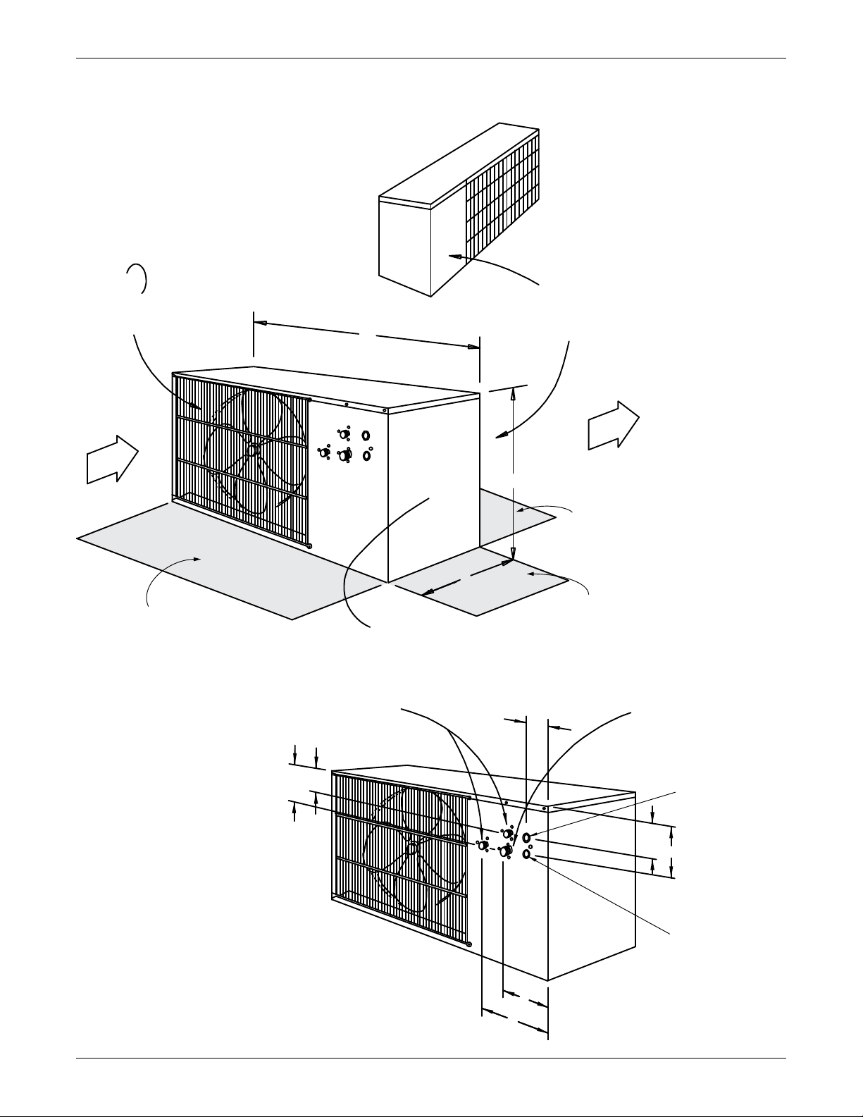
7.4 Outdoor Air-Cooled Condensing Units
A
B
C
Shaded area indicates
a minimum clearance
of 18" (457mm) for
proper air flow
Shaded area indicates
a minimum clearance
of 18" (457mm) for
proper air flow
Removable (Front) Panel
for access to high-voltage and
low-voltage connections and
refrigeration components
Shaded area indicates
a minimum clearance
of 24" (610mm) for component
access and removal
Removable (Right) Panel
for access to refrigeration
components
Right Air
Discharge
Left Air
Intake
Fan Rotation
CCW (left side)
SL-11081
Pg. 4
C
C
Liquid Line
Quick Connect
(Male Coupling)
Suction Line
Quick Connect
(Male Coupling)
Except as noted
Electrical Entrance
for High-Voltage
Connection
Electrical Entrance
for Low-Voltage
Connection
SL-11081
Pg. 6
B
C
A
F
G
D
E
UNIT DIMENSIONS
(See Table 26)
Figure 32 Outdoor air-cooled condensing unit—horizontal air discharge models
Split System Models
60
Page 67
Table 26 Horizontal air discharge cabinet and floor planning dimensional data
Model Numbers Dimensional Data in. (mm) Module
Weight
lb (kg) net60 Hz 50 Hz A B C
PFC042A-_L PFC041A-_L
PFH042A-_L —
PFC042A-_H PFC041A-_H
PFH042A-_H —
PFCZ42A-_L PFCZ41A-_L
PFC067A-_L PFC066A-_L
PFH067A-_L —
48 (1219) 31 (787) 18 (457) 241 (109)
53 (1343) 36-1/4 (918) 18 (457) 351 (159)
Table 27 Horizontal air discharge piping and electrical connection data
Model Numbers Dimensional Data in. (mm) Piping Connections in. (mm)
60 Hz 50 Hz A B C D E F G
PFC042A-_L PFC041A-_L
PFH042A-_L —
PFC042A-_H PFC041A-_H
PFH042A-_H PFCZ41A-_L
PFCZ42A-_L —
PFC067A-_L PFC066A-_L
PFH067A-_L —
2 (51) 5-3/4 (146) 8-1/2 (216) 4-3/4 (121) 6-3/4 (171) — 8-1/2 (216)
2 (51) 6 (152) 8-1/2 (216) 4-3/4 (121) 7-3/4 (197) — 8-1/2 (216)
Split System Models
61
Page 68
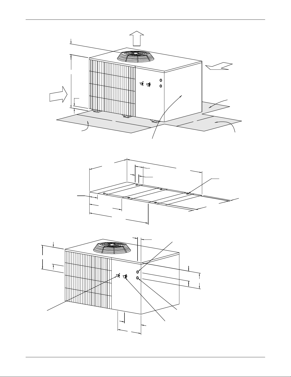
Figure 33 Outdoor air-cooled condensing unit—top air discharge models
C
A
2"
(51mm)
B
D
36-1/8"
(918mm)
25-3/32"
(637mm)
46-7/32"
(1174mm)
4-23/32"
(120mm)
53-3/16"
(1351mm)
4" (typ.)
(102mm)
2" (typ.)
(51mm)
2"
(51mm)
32-1/8"
(816mm)
FOOTPRINT
DIMENSIONS
1/2" (13mm)
Bolt-Down Holes
6 places
Shaded area indicates
a minimum clearance
of 18" (457mm) for
proper air flow
Shaded area indicates
a minimum clearance
of 18" (457mm) for
proper air flow
Removable (Front) Panel
for access to high-voltage and
low-voltage connections and
refrigeration components
Shaded area indicates
a minimum clearance
of 24" (610mm) for component
access and removal
Right Air
Discharge
Top Air
Discharge
Left Air
Intake
Guard Height
SL-11081
Pg. 5
F
G
B
C
A
D
E
Suction Line
Quick Connect
(Male Coupling)
Liquid Line
Quick Connect
(Male Coupling)
Electrical Entrance
for High-Voltage Connection
Electrical Entrance
for Low-Voltage
Connection
SL-11081
Pg. 7
UNIT DIMENSIONS
(see Table 28)
PIPING & ELECTRICAL
CONNECTIONS
(see Table 29)
Split System Models
62
Page 69
Split System Models
Table 28 Cabinet and floor planning dimensional data - prop fan condensing modules, top air discharge
Model Numbers Dimensional Data in. (mm) Module
Weight
lb (kg) net60 Hz 50 Hz A B C D
PFC067A-_H PFC066A-_H
53 (1343) 36-1/4 (918) 38-1/2 (978) 5-1/2 (140) 488 (222)PFH067A-_H —
PFCZ67A-_L PFCZ66A-_L
Table 29 Piping and electrical connections - top air discharge
Model Numbers Dimensional Data in. (mm) Piping Connections in. (mm)
60 Hz 50 Hz A B C D E F
PFC067A-_H PFC066A-_H
2 (51) 6 (152) 8-1/2 (216) 4-3/4 (121) 7-3/4 (197) 8-1/2 (216)PFH067A-_H —
PFCZ67A-_L PFCZ66A-_L
63
Page 70
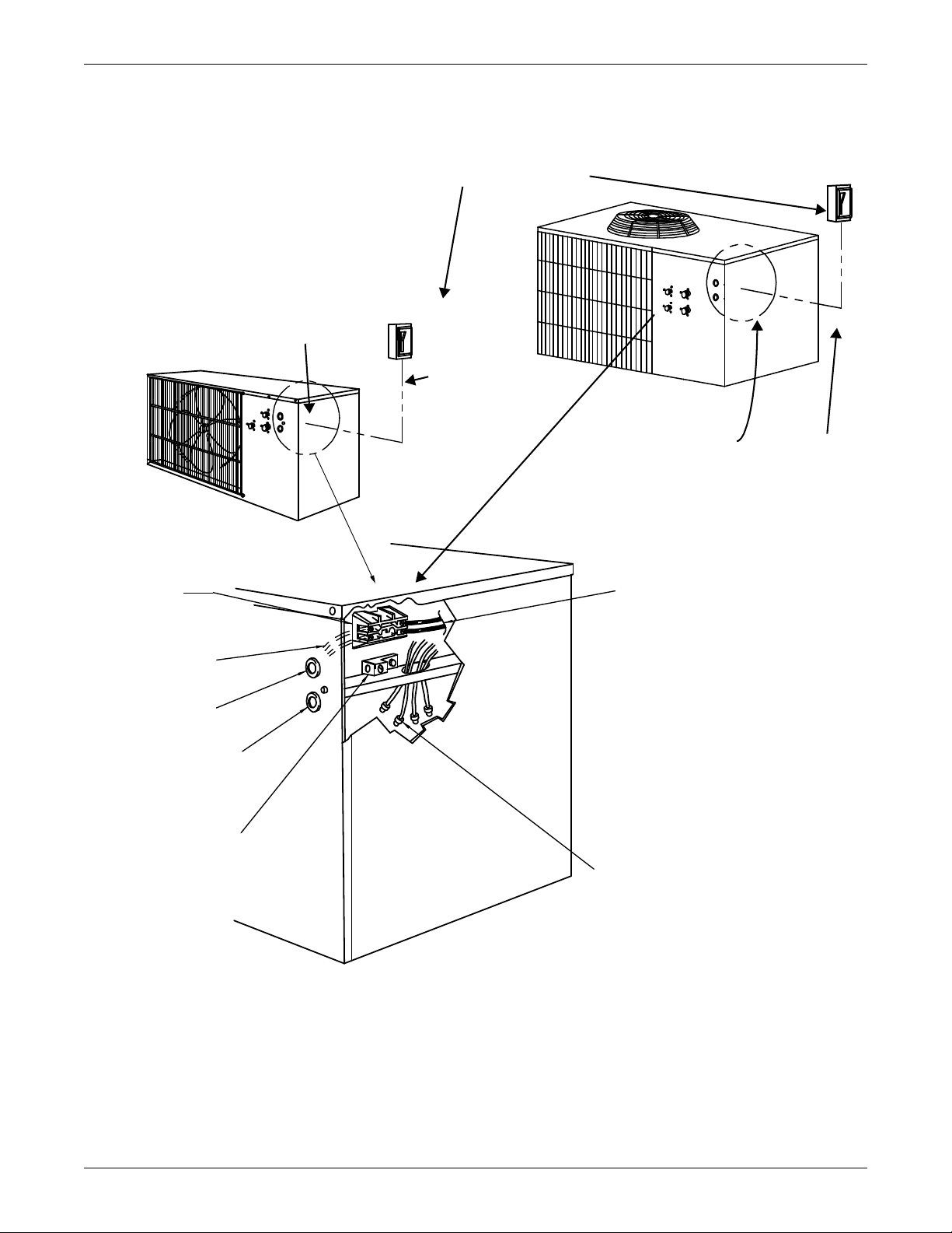
Figure 34 Electrical field connections, prop fan condensing module
NOTE: Refer to specification sheet for full load amp
and wire size amp ratings
SL-11081 Pg. 8
Factory-wired
to components on
electric panel.
Heat rejection connection. Field
supplied 24V NEC class 2 wiring.
Wire connections from evaporator module:
1. 24V GND
2. 24V Supply
3. High Pressure Alarm
4. Hot Gas Bypass Connection
(only on units with hot gas bypass.
If no hot gas bypass, connection is
provided in the evaporator module.
Connect wire 4 with wire 2 to the
24V supply).
Electric service
connection to contactor
or terminal block
Single- or 3-phase
electric service; not
by Liebert
High-voltage electric
power supply entrance
Low-voltage electric
power supply entrance
Earth ground connection
terminal for field wiring.
SL-11081
Pg. 8A
TOP AIR
DISCHARGE MODELS
(5-Ton High Ambient
& 5-Ton Quiet-Line)
HORIZONTAL AIR DISCHARGE MODELS
Single- or
3-phase
electric
service; not
by Liebert
Field-supplied 24V NEC
Class 2 wiring to
evaporator module
Single- or
3-phase electric
service; not by
Liebert
Field-supplied unit
disconnect switch
Field-supplied 24V
NEC Class 2 wiring
to evaporator
module
Split System Models
64
Page 71
7.5 Centrifugal Air-Cooled Condensing Units
!
7.5.1 Installing the Indoor Condensing Unit
Refer to drawings for unit dimensions and component locations.
WARNING
Risk of heavy unit falling from supports. Can cause equipment and building damage, injury
and death.
Be sure the supporting roof structure is capable of supporting the weight of the unit(s) and
the accessories during installation and service. (See Table 30 - Indoor centrifugal
condensing unit.)
Be sure to securely anchor the top ends of the suspension rods. Make sure all nuts are tight.
The indoor condensing unit is usually mounted above the ceiling and must be securely mounted to the
roof structure. The ceiling and ceiling supports of existing buildings may require reinforcements. Be
sure to follow all applicable codes. Use field-supplied threaded suspension rods and 3/8"-16 factory
hardware kit.
The indoor condensing unit must be located at the same level or above the Liebert Challenger 3000
unit. It must NOT be located below the Liebert Challenger 3000.
Recommended clearance between ceiling grids and building structural members is unit height plus
three inches.
Split System Models
Install the four field-supplied rods by suspending them from suitable building structural members.
Locate the rods so that they will align with the four mounting holes in the flanges that are part of the
unit base.
Using a suitable lifting device, raise the unit up and pass the threaded rods through the four mounting holes in the flanges that are part of the unit base.
Attach the threaded rods to the unit flanges using the supplied nuts and grommets. (See Figure 35 -
Detail of ceiling hanging bracket, Threaded Rod and Hardware Kit Installation). The rubber
grommets provide vibration isolation.
1. Use the plain nuts to hold unit in place. Adjust these nuts so that the weight of the unit is
supported evenly by the four rods, does not rest on the ceiling grid, and is level.
NOTE
The units must be level in order to operate properly.
2. Use the Nylock nuts to “jam” the plain nuts.
Table 30 Indoor centrifugal condensing unit
Model
MC_40A MC_39A 240 (109)
MC_65A MC_64A 449 (204)
Net Weight
lb (kg)60 Hz 50 Hz
65
Page 72
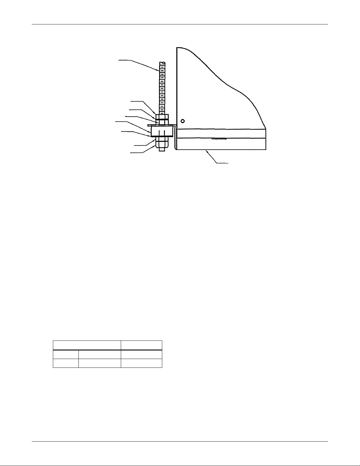
Figure 35 Detail of ceiling hanging bracket
3/8" threaded rod
(field-supplied)
3/8" hex nut
3/8" washer
Sleeve
Isolator
3/8" fender washer
3/8" hex nut
3/8" hex nut
Nylock
Unit base pan (ref)
7.5.2 Ducting
The total external static pressure for the inlet and outlet ducts, including grille, must not exceed
0.5 inches of H
sions.
O. Hood intake dimensions should be the same as the condensing unit duct dimen-
2
Split System Models
If the condensing unit is located close to the outside of the building, rain hoods must be installed. In
addition, install a triple layer bird screen over rain hood openings to eliminate the possibility of
insects, birds, water, or debris entering the unit.
Use flexible ductwork or nonflammable cloth collars to attach ductwork to the unit and to control
vibration transmission to the building. Attach the ductwork to the unit using the flanges provided.
Locate the unit and ductwork so that the return air does not short circuit to the supply air inlet.
Avoid directing the hot exhaust air toward adjacent doors or windows.
Normal operating sound may be objectionable if the condensing unit is placed directly over quiet work
areas. Ductwork that runs through a conditioned space or is exposed to areas where condensation
may occur must be insulated. Whenever possible, ductwork should be suspended using flexible hangers. Ductwork should not be fastened directly to the building structure. In applications where the ceiling plenum is used as the heat rejection domain, the discharge air must be directed away from the
condensing unit air inlet and a screen must be added to the end of the discharge duct to protect service personnel.
For multiple unit installations, space the units so that the hot condensing unit exhaust air is not
directed toward the air inlet of an adjacent unit.
Table 31 Airflow CFM (CMH)
3-Ton 5-Ton
60 Hz 2000 (3398) 3500 (5947)
50 Hz 1650 (2800) 3500 (5947)
66
Page 73
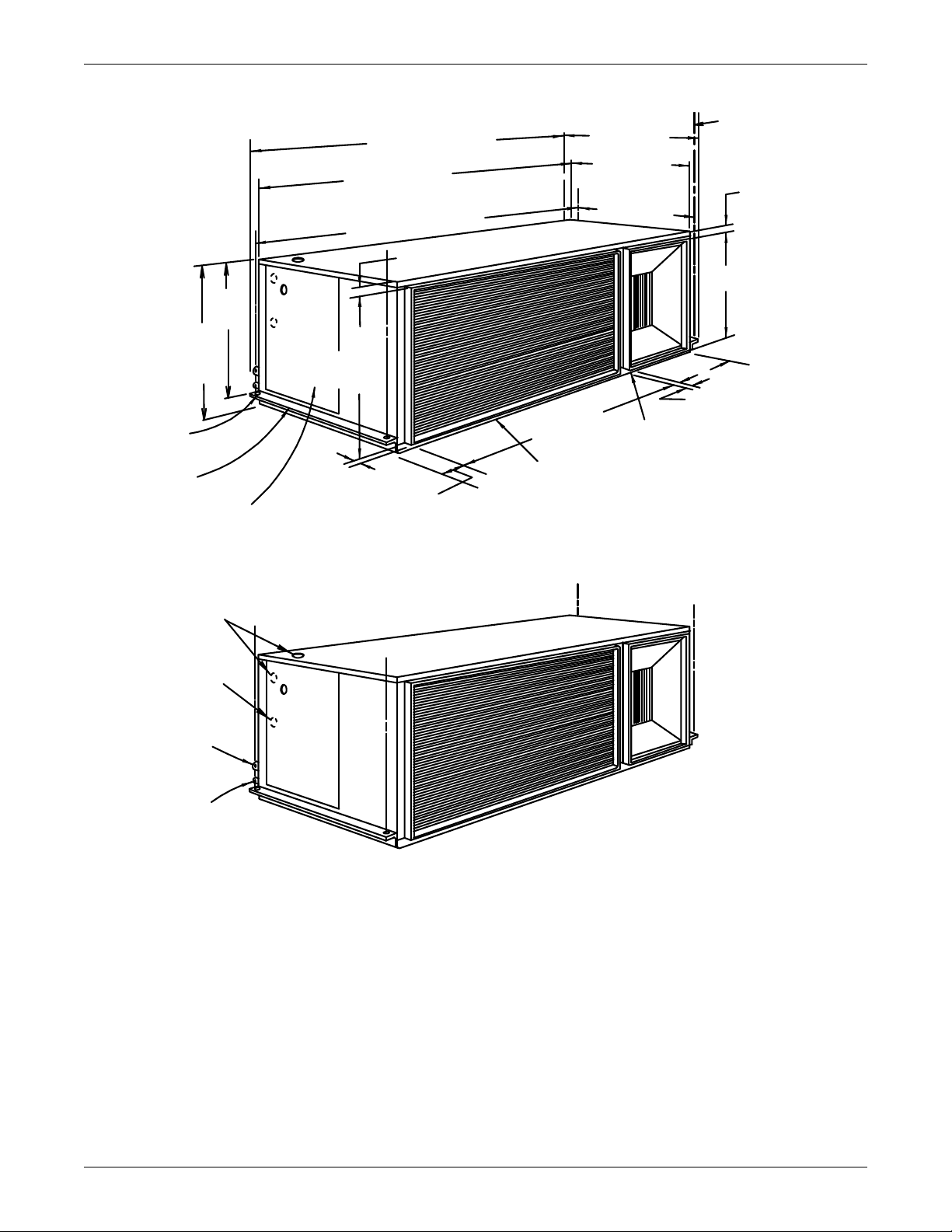
Split System Models
C
D
B
A
Customer-supplied
threaded rods for
module support
from ceiling (typ. 4)
SL-11085 Pg. 4
Air Outlet
Duct Connection
Air Outlet
Duct Dimension
Note:Unit is evenly spaced in
reference to threaded for centers.
PIPING CONNECTIONS
DIMENSIONAL DATA
Blower Motor Service Access
Panel on Bottom of Unit
Minimum Clearance 33" (838mm)
for Component Access and Removal.
50-1/4" (1276mm)
Overall Dimension
46-1/2" (1181mm)
Cabinet Dimension
48-1/4" (1225mm)
Threaded Rod Centers
21-1/2" (546mm )
Cabinet Dimension
22-1/2"
(572mm)
Cabinet
Dimension
19-1/2" (495mm)
Threaded Rod
Centers
Duct Flange
2-1/4"
(57mm)
1"
(25.4mm)
20-7/16"
(519mm)
Coil Inlet
Duct
Conn.
Minimum Clearance 33" (838mm)
This End for Component Access
and Removal
20-3/4"
(527mm)
1/2" (13mm)
7/8" (22.2mm) Dia.
Electrical Entrance
for Low-Voltage
Connection
30-1/8"
(765mm)
Coil Inlet
Duct Connection
Liquid Line
Male Quick
Connect
Suction Line
Male Quick
Connect
Integral Hanging
Bracket
Holes for Module
Rigging (typ. 2 each end)
7/8" (22.2mm) Dia.
Electrical Entrance
for Line-Voltage
Connection
22-3/4" (578mm)
Overall Dimension
Figure 36 3-ton centrifugal air-cooled condensing unit dimensional data & piping connections
67
Page 74
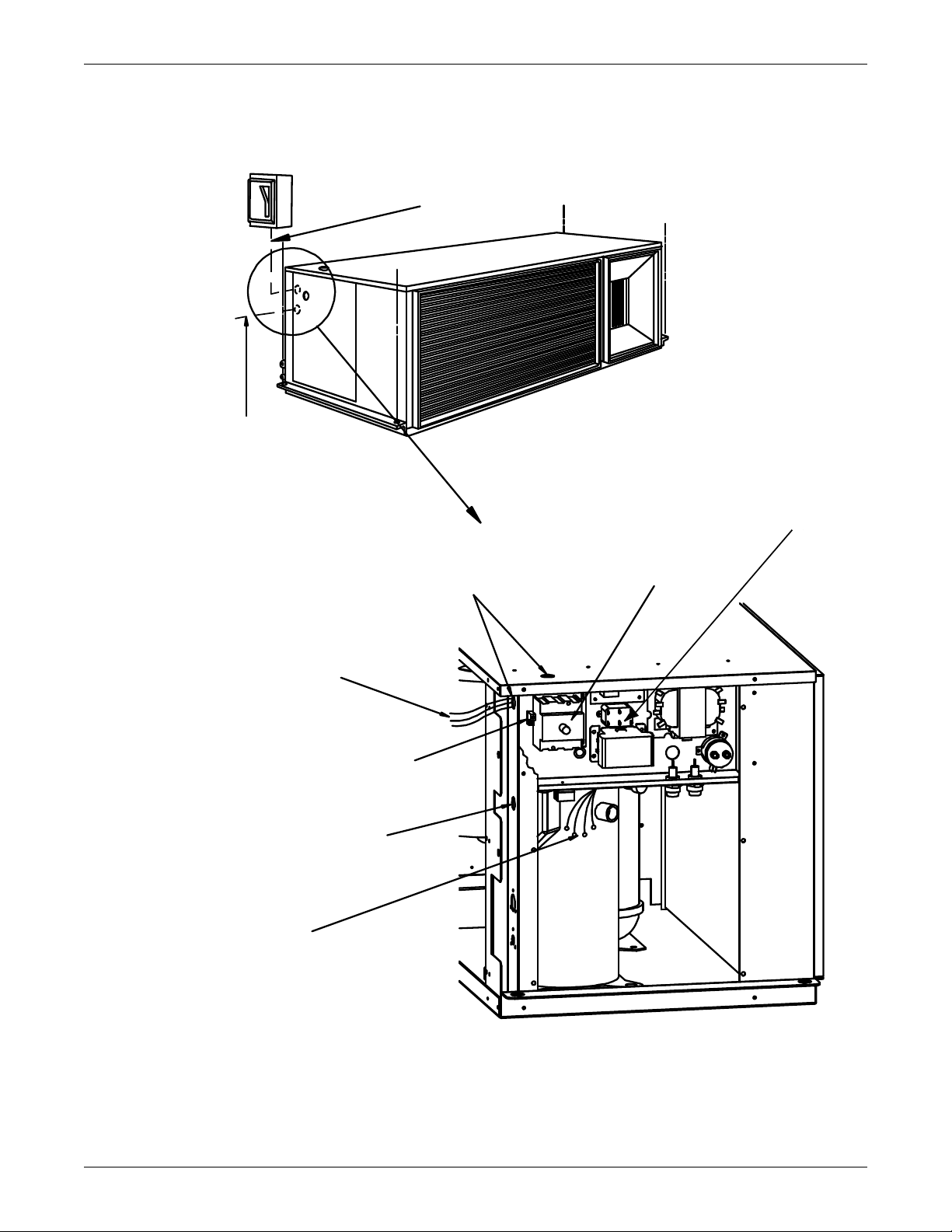
Figure 37 3-ton centrifugal air-cooled condensing unit (con't.)
DPN000207
Rev0
Single- or three-phase
electric service
not by Liebert
Optional factory-installed
disconnect switch
Factory-wired
to components
on electric panel
Line voltage electric power
supply conduit entrance
Field-supplied 24V
NEC Class 2 wiring
to fan/coil unit
Single- or three-phase
electric service
not by Liebert
Field-supplied unit disconnect
switch when optional disconnect
is not provided in unit
Connection terminal
for field-supplied
grounding wire
Low-voltage electric
power supply entrance
Heat rejection connection.
Field-supplied 24V NEC
Class 2 wiring. See NOTE 2.
NOTES:
1. Refer to specification sheet for full load amp. and wire size amp. ratings.
2. Control voltage wiring must be a minimum of 16 GA (1.6mm) for up to 75' (23m)
or not to exceed 1 volt drop in control line.
Wire connections from evaporator
mod:
1. 24V ground
2. 24V supply
3. High-pressure alarm (optional)
4. Hot gas bypass connection
(only on units with hot gas
bypass)
Split System Models
68
Page 75
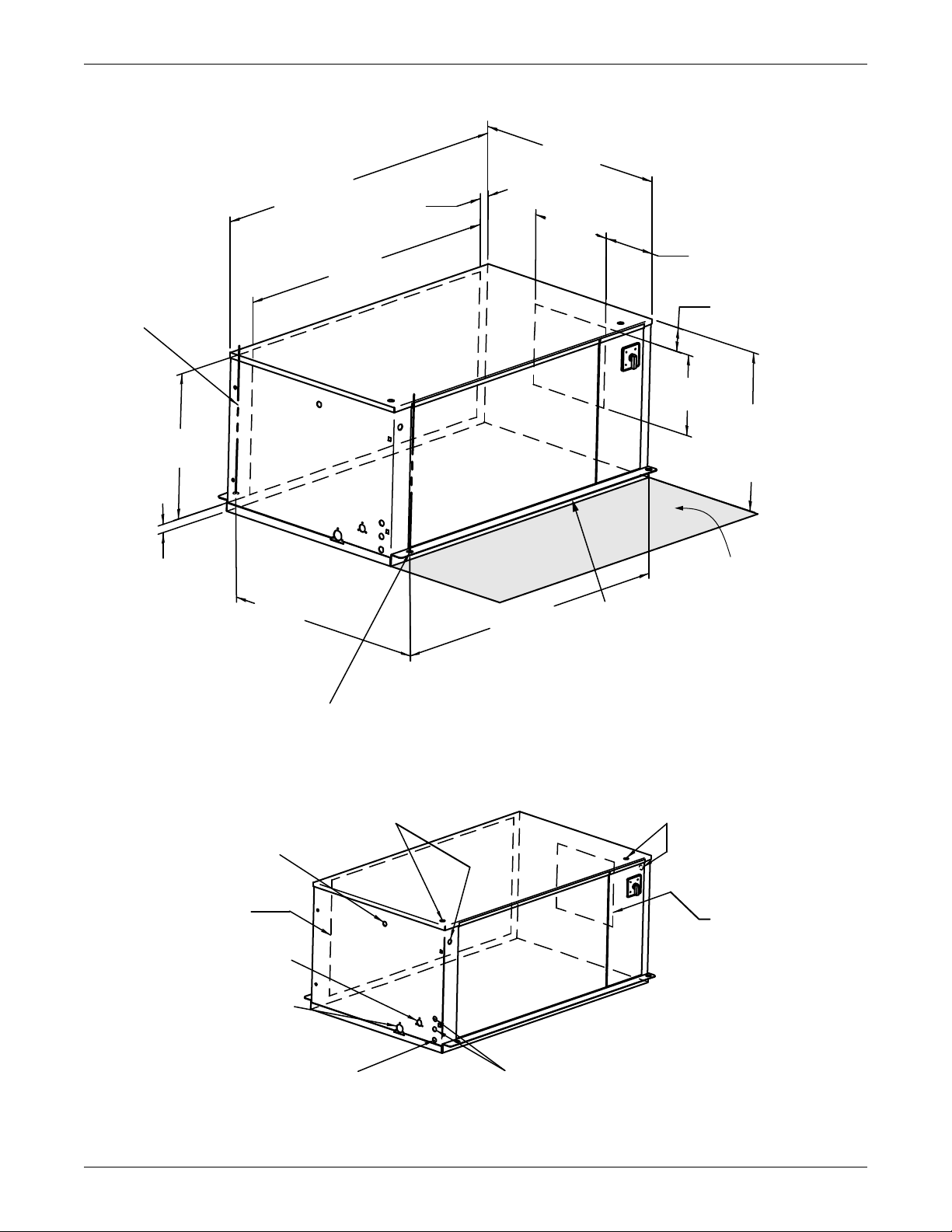
Figure 38 5-ton centrifugal air-cooled condensing unit dimensional data
SL-11087 Pg. 4
24"
(610mm)
Cabinet
Dimension
32"
(812.8mm)
Cabinet
Dimension
3-3/8"
(85.7mm)
14-1/2"
(368.3mm)
8-15/16"
(227mm)
15-3/4"
(400mm)
1-5/8"
(41.1mm)
54"
(1371.6mm)
Cabinet
Dimension
1-3/4"
(44.5mm)
51-13/16"
(1316mm)
Threaded Rod
Centers
21-1/4"
(539.8mm)
48"
(1219.2mm)
33-5/8"
(854.1mm)
Threaded Rod
Centers
Hanger
Bracket
Shaded area indicates a
recommended clearance of
30" (762mm) for component
access and removal.
1/2" (12.7mm) dia. holes for
threaded rods (typ. 2 each end)
Air
Outlet
Air Inlet
7/8" (22.2mm) & 1-1/8" (28.6mm)
dia. knockouts electrical entrance for highvoltage connection (Single Point Power Kit)
7/8" (22.2mm) & 1-1/8" (28.6mm)
dia. knockouts electrical entrance
for high-voltage connection
Suction Line male quick
connect location
Liquid Line male quick
connect location
Single Point Power Kit
connection to Evaporator
NOTE: Unit is spaced evenly in
reference to threaded
rod centers.
7/8" (22.2mm) dia.
electrical entrance
for low voltage connection
7/8" (22.2mm) dia. knockout
electrical entrance for alternate
control panel low-voltage routing
Split System Models
69
Page 76
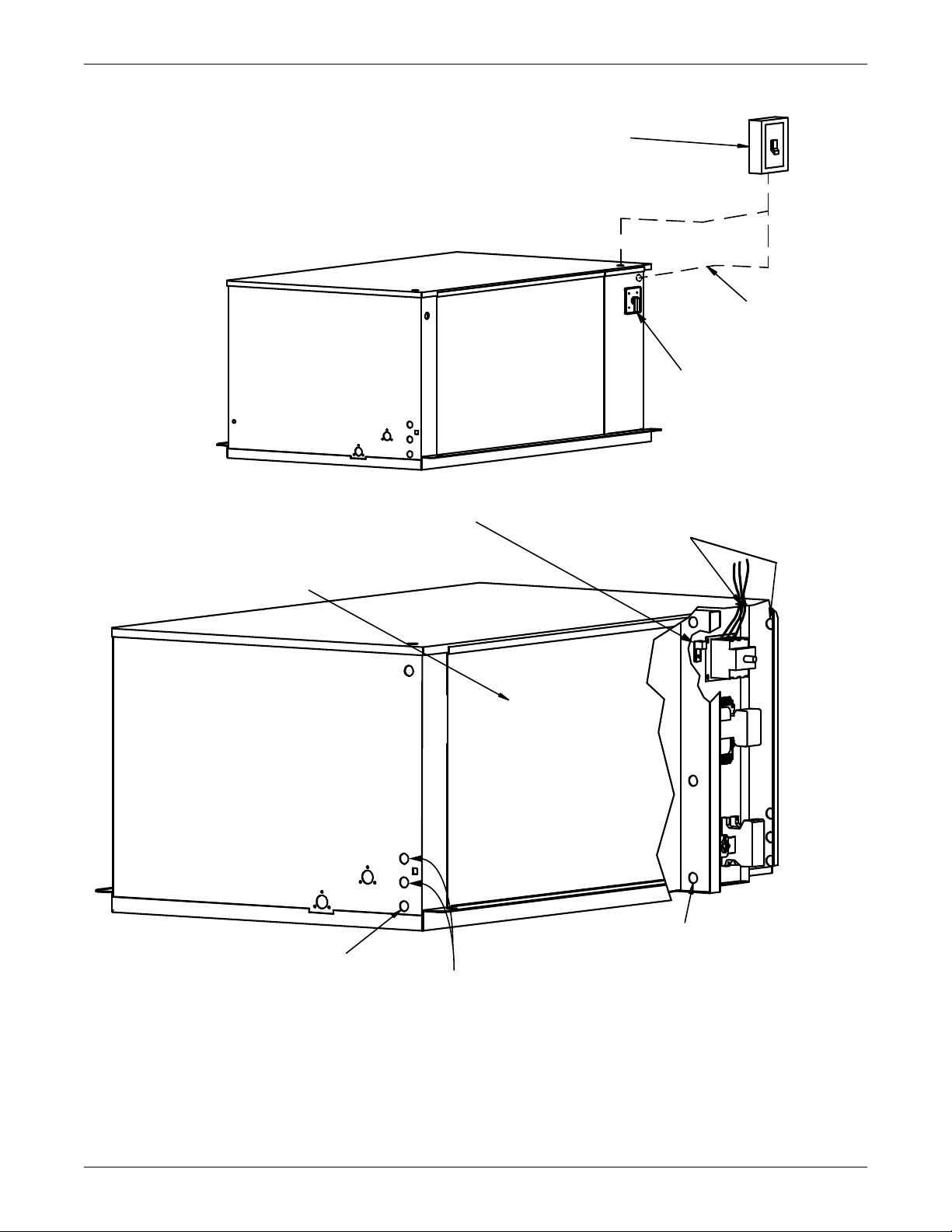
Figure 39 5-ton centrifugal air-cooled condensing unit dimensional data (con't.)
DPN000226_Rev0
Field-Supplied Unit Disconnect
Switch when Factory Unit
Disconnect Switch is not Supplied
Electric service
not by Liebert
Optional
Factory-Installed
Disconnect Switch
AIR COOLED
Line Voltage Electric Power
Supply Conduit Voltage
Connection terminal
for field-supplied
earth grounding wire
Removable Access Panels
Field-Supplied 24V NEC Class 2
wiring between condensing unit
and fan/coil unit
Low-voltage
electric power
supply conduit
entrance
Heat rejection connection. Field-supplied
24V NEC Class 2 wiring. See Note 2.
Wire connections from evaporator module.
1. 24V GND
2. 24V supply
3. High pressure alarm (optional)
4. Hot gas bypass connection (only on
units with hot gas bypass)
NOTES:
Refer to specification sheet for full load amp and wire size amp ratings.
Control voltage wiring must be a minimum of 16 G A (1.6mm) for up
to 75’ (23m) or not to exceed 1 volt drop in control line.
Split System Models
70
Page 77
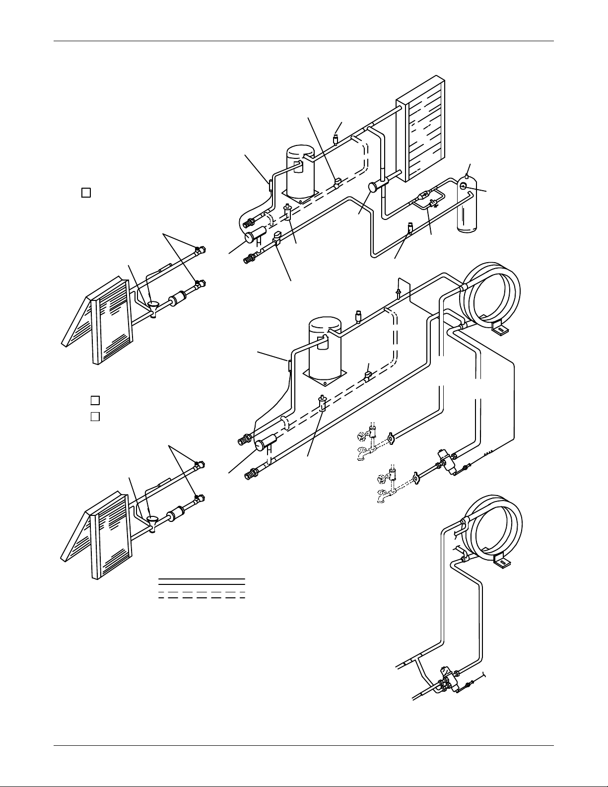
Figure 40 Split systems general arrangement
Condenser
Coil
1/2" (12.7mm) NPT
Pressure Relief Valve
Pressure
Balancing
Val ve
Sight
Glass
Check
Val ve
Lee-Temp
Receiver
High-Pressure
Switch
Scroll
Compressor
Scroll
Compressor
Head-Pressure
Control with
Integral Check
Val ve
Liquid Line
Solenoid Valve
Suction Line
Male Quick
Connect
Coupling*
Suction Line
Male Quick
Connect
Coupling*
Liquid Line
Male Quick
Connect
Coupling*
Suction Line
Female Quick
Connect
Coupling*
Suction Line
Female Quick
Connect
Coupling*
Liquid Line
Female Quick
Connect
Coupling*
Liquid Line
Male Quick
Connect
Coupling*
Liquid Line
Female Quick
Connect
Coupling*
Filter
Dryer
Filter
Dryer
Service
Access
Ports
Service
Access
Ports
Sensing
Bulb
Sensing
Bulb
Expansion
Val ve
Expansion
Val ve
External
Equalizer
External
Equalizer
Evaporator
Coil
Evaporator
Coil
High-Pressure
Switch
Tube in
Tube
Condenser
Tube in
Tube
Condenser
Water/Glycol
Return
Line
AIR COOLED
WATER COOLED
GLYCOL COOLED
Liquid Injection
Val v e Bulb
Liquid Injection
Val ve Bu lb
Hot-Gas
Bypass Solenoid
Val ve
Hot-Gas
Bypass
Solenoid
Val ve
Hot-Gas
Bypass Control
Val ve
Hot-Gas
Bypass Control
Val ve
Receiver Heater
Pressure Limiting
Switch
Water/Glycol
Supply Line
Liquid
Injection
Val ve
Liquid
Injection
Val ve
SL-11900 Pg. 5
Fluid Supply
to Unit
Shutoff
Val ves *
Hose Bibs *
Fluid Return
from Unit
Fluid
Return
from Unit
Fluid Supply
to Unit
3-Way Water
Regulating Valve (optional)
2-Way Water
Regulating Valve
OPTIONAL PIPING
FACTORY PIPING
* Components are not supplied by Liebert but
are recommended for proper circuit operation
maintenance.
Split System Models
71
Page 78
7.6 Water and Glycol-Cooled Condensing Units
For installation guidelines, refer to Installing the Indoor Condensing Unit on page 65.
7.6.1 Piping Considerations
It is recommended that manual service shut-off valves be installed at the supply and return line to
each unit. This will provide for routine service or emergency isolation of the unit.
When the water source for the condenser is of poor quality, it is good practice to provide cleanable filters in the supply line. These filters will trap the particles in the water supply and extend the service
life of the water-cooled condenser.
3-Ton Connection Sizes
Condenser Water Inlet 7/8" OD Cu
Condenser Water Outlet 7/8" OD Cu
Suction Line 1-1/8 - 12 male #11 quick connect
Liquid Line: 5/8 - 18 male #6 quick connect
5-Ton Connection Sizes
Condenser Water Inlet 1-1/8" OD Cu
Condenser Water Outlet 1-1/8" OD Cu
Suction Line 1-7/16" - 16 male #12 quick connect
Liquid Line 1-1/16" - 12 male #10 quick connect
Split System Models
Table 32 Water and glycol-cooled condensing unit data
Model
MC_44W
MC_43W
MC_69W
MC_68W
Net Weight,
lb (kg)
200 (91) 1.7 (6.4)
282 (128) 2.0 (7.6)
Glycol Volume,
gal (l)
7.6.2 Condenser Water Requirements
The standard maximum water pressure is 150 psig (1034 kPa). For applications above this pressure,
consult the factory about high pressure systems.
The system will operate in conjunction with a cooling tower, city water, or drycooler.
7.6.3 Regulating Valve
For details, refer to sections 4.3.1 - Standard Valve - 150psig (1034kPa) System for 3 & 5-Ton
Units (Johnson Controls Valve) High Pressure Valve - 350psig (2413 kPa) System for 5-Ton
Units (Johnson Controls Valve) and 4.3.2 - High Pressure Valve - 350 psig (2413 kPa) System
for 3-Ton Units (Metrex Valve).
72
Page 79
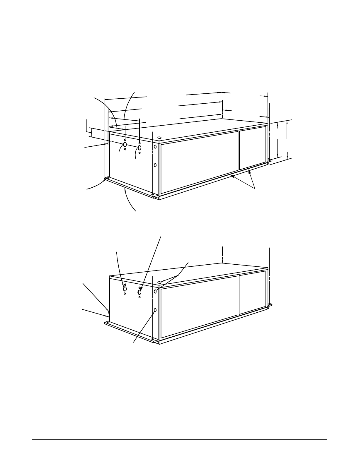
7.6.4 Glycol Systems
Suction Line
Male Quick
Connect
20-3/4"
(527mm)
46-1/2" (1181mm)
Minimum Clearance
33" (838mm) This side
for component access
and removal
Customer-Supplied
Threaded Rods for Module
Support from Ceiling (typ. 4)
Outlet
Inlet
DIMENSIONAL DATA
3/4" (19mm) NPT Female
Water/Glycol Outlet Connection
Integral Hanging Bracket
22-1/2"
(572mm)
SL-11085 Pg. 6
PIPING CONNECTIONS
12" (305mm)
Threaded Rod
Centers
14" (356mm)
Overall Cabinet
Dimension
Holes for Module
Rigging (typ. 2 each end)
3/4" (19mm) NP T Female
Water/Glycol Inlet Connection
7/8" (22mm) Dia.
Electrical Entrance
for Low-Voltage Connection
7/8" (22mm) Dia.
Electrical Entrance
for High-Voltage
Connection
Liquid Line
Male Quick
Connect
Cabinet
Dimension
Cabinet Dimension
8-7/16" (214mm)
8-7/8" (225mm)
50-1/4" (1276mm)
Overall Dimension
48-1/4" (1225mm)
Threaded Rod Centers
3-7/8" (98mm)
For split system glycol systems, use drycooler and pump data found in 5.0 - Glycol/GLYCOOLCooled Models—Self-Contained Compressor. See Table 18 - Drycooler data.
Electrical control interconnect to drycooler is wired from water/glycol condensing unit.
Figure 41 3-ton water/glycol-cooled condensing unit
Split System Models
73
Page 80
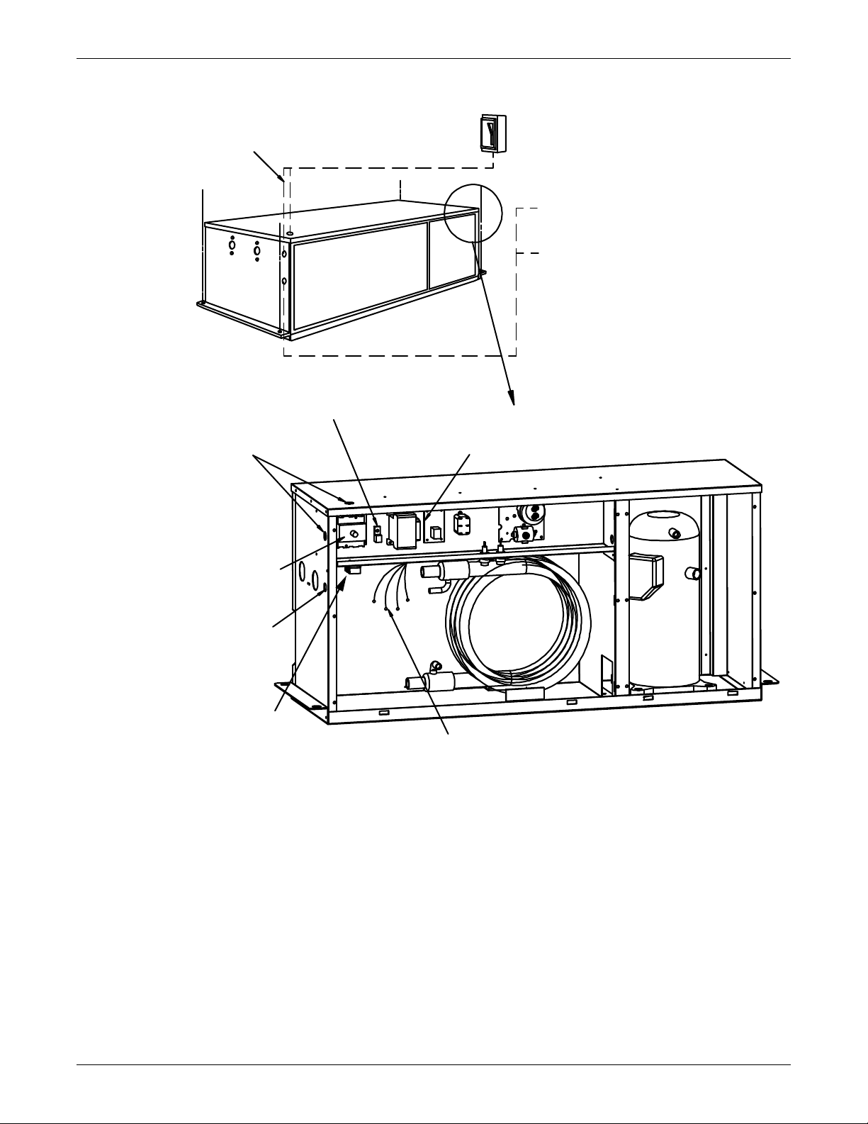
Figure 42 3-ton water/glycol-cooled condensing unit (con't.)
DPN000209_Rev0
Single- or
three-phase
electric service
not by Liebert
Field-supplied unit disconnect
switch when optional disconnect
is not provided in unit
Field-supplied 24V NEC Class 1
wiring to fan/coil unit
Field-supplied 24V NEC Class 1
wiring to drycooler
(glycol-cooled units only)
Earth/ground connection
Connection terminal for field-supplied
earth-grounding wire
Line-voltage electric
power supply entrance
Factory-wired components
on electric panel
Optional factory-installed
disconnect switch
Low-voltage electric
power supply entrance
Remote drycooler connection
Terminals 70 & 71 supplied
for connection to remote drycooler
Use field-supplied 24V NEC Class 1
wiring (glycol-cooled units only)
Heat rejection connection.
Field-supplied 24V NEC Class 2 wiring.
Wire connections from evaporator mod:
1. 24V GND
2. 24V supply
3. High-pressure alarm (optional)
4. Hot gas bypass connection
(only on units with hot-gas bypass)
NOTES
1. Refer to specification sheet for full load amp
and wire size amp ratings.
2. Control voltage wiring must be a minimum
of 16 GA (1.6mm) for up to 75' (23m) or
not to exceed 1 volt drop in control line.
Split System Models
74
Page 81
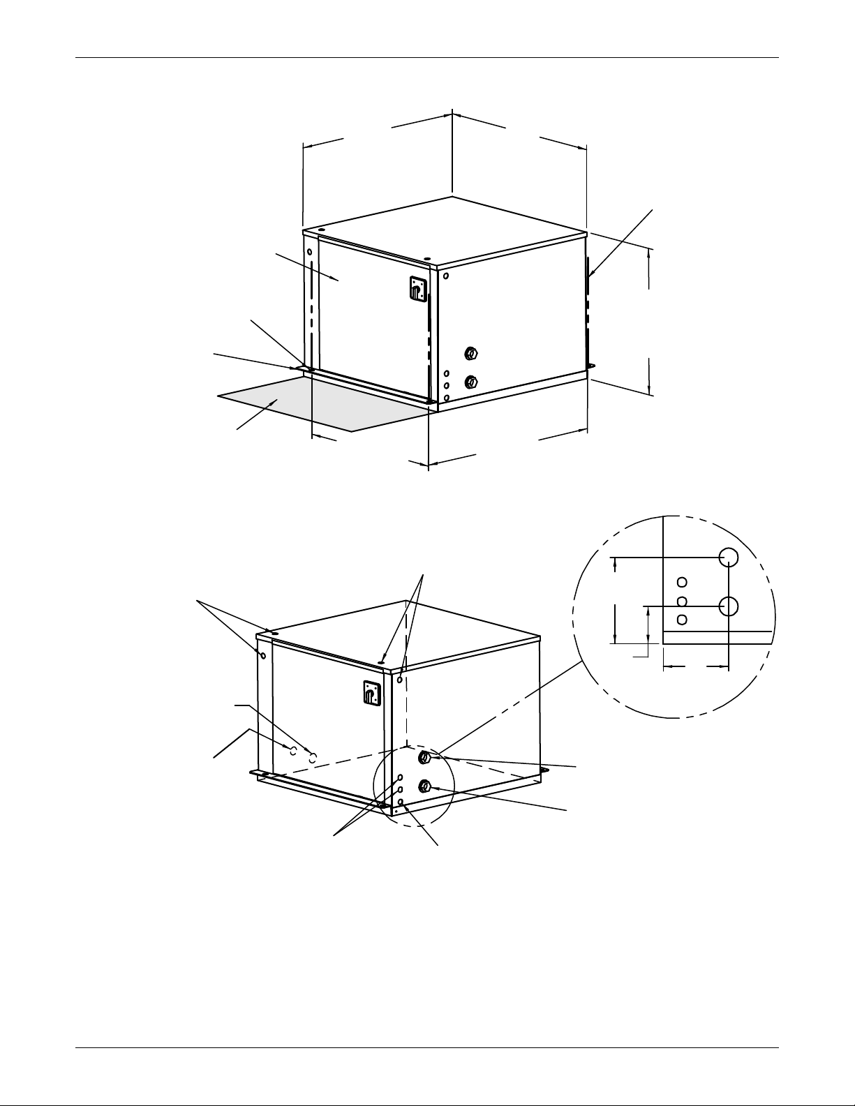
Figure 43 5-ton water/glycol-cooled condensing unit dimensional data
7/8" (22.2mm) & 1-1/8" (28.6mm)
dia. knockouts electrical entrance for
line voltage connection (Single Point
Power Kit)
Removable
Access Panel
1/2" (12.7mm) dia. holes for
module rigging (typ. 2 each end)
Customer-supplied
threaded rods
for module support
from ceiling (typ. 4).
NOTE: Unit is evenly spaced in reference
to threaded rod centers.
1" (25.4mm) NPT Female
Water/Glycol Outlet Connection
1" (25.4mm) NPT Female
Water/Glycol Inlet Connection
7/8" (22.2mm) dia. knockout
electrical entrance for alternate
control panel low-voltage routing
7/8" (22.2mm) dia. electrical entrance
for low-voltage connection
Suction Line male quick
connect location
Liquid Line male quick
connect location
7/8" (22.2mm) & 1-1/8" (28.6mm)
dia. knockouts electrical entrance
for line voltage connection
32"
(812.8mm)
Cabinet
Dimension
32"
(812.8mm)
Cabinet
Dimension
24 "
(610mm)
Cabinet
Dimension
33-5/8"
(854.1mm)
Threaded Rod
Centers
29-13/16 "
(757.2mm)
Threaded Rod
Centers
7"
(177.8mm)
SL-11087
Pg. 6
Hanger
Bracket
Shaded area indicates a
recommended clearance of
30" (762mm) for component
access and removal.
8-7/16"
(214.4mm)
3-3/4"
(95.2mm)
Split System Models
75
Page 82
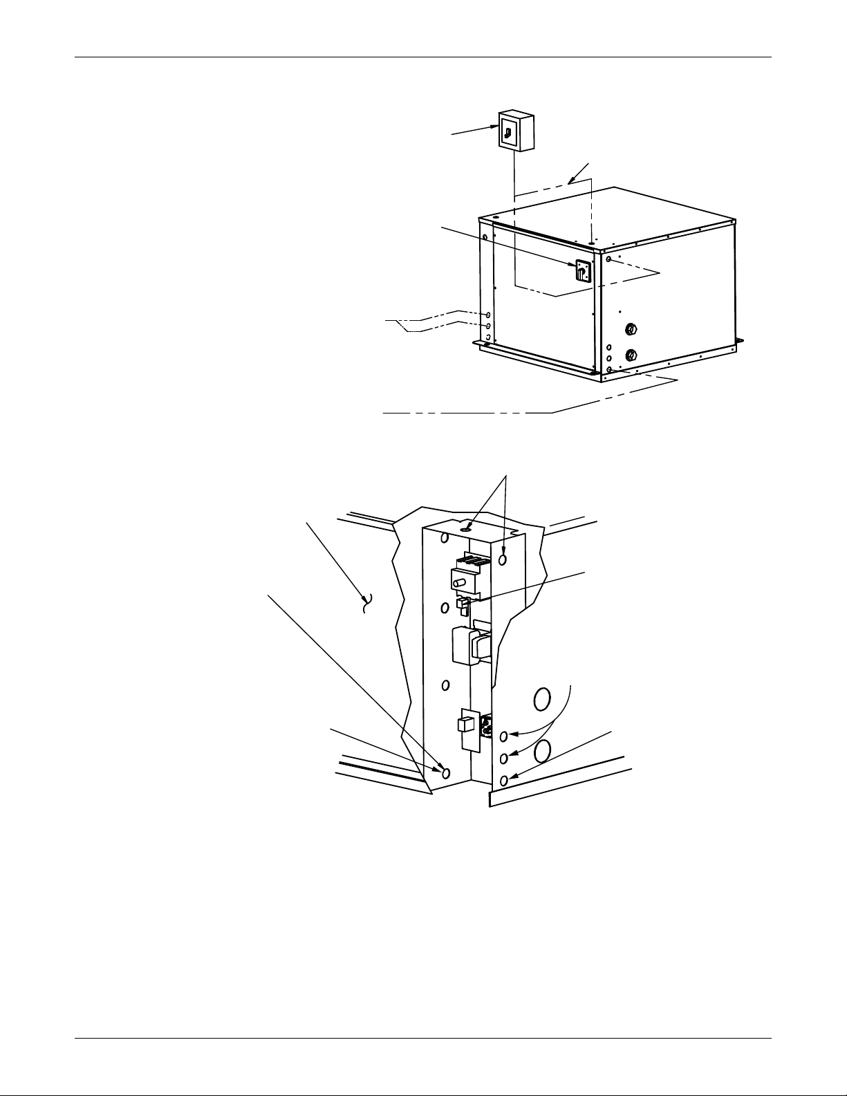
Figure 44 5-ton water/glycol-cooled condensing unit (con't.)
DPN000228_Rev0
Field-supplied unit disconnect
switch when factory unit
disconnect switch is not suplied
Electric service;
not by Liebert
WATER/GLYCOL
Optional factory-installed
disconnect switch
Field-supplied 24V
NEC Class 1 wiring
to fan/coil unit
Field-supplied 24V
NEC Class 1 wiring
to drycooler
(glycol-cooled units only)
Line voltage electric
power supply conduit voltage
Removable
Access Panel
Heat rejection connection.
Field-supplied 24V NEC Class 2 wiring.
Wire connections from evaporator mod:
1. 24V ground
2. 24V supply
3. High pressure alarm (optional)
4. Hot gas bypass connection
(only on units with hot gas bypass)
Remote drycooler
connection; field-supplied
24V NEC Class 1 wiring
(glycol-cooled units only)
Connection terminal
for field-supplied
earth grounding wire
Low-voltage electric
power supply conduit
entrance
Field-supplied 24V NEC
Class 1 wiring between
glycol condensing unit
and drycooler
NOTES
1. Refer to specification sheet for full load amp. and wire size amp. ratings.
2. Control voltage wiring must be a minimum of 16 G A (1.6mm) for up to 75' (23m)
or not to exceed 1 volt drop in control line.
Split System Models
76
Page 83
R407C Refrigerant
8.0 R407C REFRIGERANT
Table 33 R407C pressure/temperature chart for operation and superheat (discharge/hot gas and suction
gas)
Temperature Gauge Pressure Temperature Gauge Pressure Temperature Gauge Pressure
°F °C Psig kPa °F °C Psig kPa °F °C Psig kPa
0.0 -17.8 18.9 130 35.0 1.7 54.8 378 70.0 21.1 114.9 792
1.0 -17.2 19.6 135 36.0 2.2 56.1 387 72.0 22.2 119.3 822
2.0 -16.7 20.4 141 37.0 2.8 57.5 396 74.0 23.3 124 853
3.0 -16.1 21.2 146 38.0 3.3 58.9 406 76.0 24.4 128 885
4.0 -15.6 22.0 152 39.0 3.9 60.3 415 78.0 25.6 133 917
5.0 -15.0 22.8 157 40.0 4.4 62.2 429 80.0 26.7 138 950
6.0 -14.4 23.6 163 41.0 5.0 63.1 435 82.0 27.8 143 984
7.0 -13.9 24.5 169 42.0 5.6 64.6 445 84.0 28.9 148 1019
8.0 -13.3 25.4 175 43.0 6.1 66.1 456 86.0 30.0 153 1054
9.0 -12.8 26.2 181 44.0 6.7 67.6 466 88.0 31.1 158 1091
10.0 -12.2 27.1 187 45.0 7.2 69.1 476 90.0 32.2 164 1128
11.0 -11.7 28.0 193 46.0 7.8 70.7 487 92.0 33.3 169 1167
12.0 -11.1 28.9 200 47.0 8.3 72.2 498 94.0 34.4 175 1206
13.0 -10.6 29.9 206 48.0 8.9 73.8 509 96.0 35.6 181 1246
14.0 -10.0 30.8 213 49.0 9.4 75.4 520 98.0 36.7 187 1287
15.0 -9.4 31.8 219 50.0 10.0 77.1 531 100.0 37.8 193 1329
16.0 -8.9 32.8 226 51.0 10.6 78.7 543 102.0 38.9 199 1372
17.0 -8.3 33.8 233 52.0 11.1 80.4 554 104.0 40.0 205 1416
18.0 -7.8 34.8 240 53.0 11.7 82.1 566 106.0 41.1 212 1461
19.0 -7.2 35.8 247 54.0 12.2 83.9 578 108.0 42.2 219 1507
20.0 -6.7 36.9 254 55.0 12.8 85.6 590 110.0 43.3 225 1553
21.0 -6.1 38.0 262 56.0 13.3 87.4 603 112.0 44.4 232 1601
22.0 -5.6 39.0 269 57.0 13.9 89.2 615 114.0 45.6 239 1650
23.0 -5.0 40.1 277 58.0 14.4 91.0 628 116.0 46.7 247 1701
24.0 -4.4 41.3 284 59.0 15.0 92.9 640 118.0 47.8 254 1752
25.0 -3.9 42.4 292 60.0 15.6 94.8 653 120.0 48.9 262 1804
26.0 -3.3 43.6 300 61.0 16.1 96.7 666 122.0 50.0 269 1858
27.0 -2.8 44.7 308 62.0 16.7 98.6 680 124.0 51.1 277 1912
28.0 -2.2 45.9 317 63.0 17.2 100.5 693 126.0 52.2 285 1968
29.0 -1.7 47.1 325 64.0 17.8 102.5 707 128.0 53.3 294 2025
30.0 -1.1 48.4 333 65.0 18.3 104.5 721 130.0 54.4 302 2083
31.0 -0.6 49.6 342 66.0 18.9 106.5 735 132.0 55.6 311 2143
32.0 0.0 50.9 351 67.0 19.4 108.6 749 134.0 56.7 320 2203
33.0 0.6 52.1 359 68.0 20.0 110.7 763 136.0 57.8 329 2265
34.0 1.1 53.5 369 69.0 20.6 112.8 778 138.0 58.9 338 2329
- - - - - - - - 140.0 60.0 347 2393
NOTE
Use this table for superheat and for control adjustment (e.g., pressure switches). See
Table 34 for subcooling.
77
Page 84
R407C Refrigerant
Table 34 R407C pressure/temperature chart for subcooling only (liquid measurements)
Temperature Pressure Gauge Temperature Pressure Gauge Temperature Pressure Gauge
°F °C Psig kPa °F °C Psig kPa °F °C Psig kPa
36.0 2.2 73 500 59.0 15.0 114 786 94.0 34.4 203 1402
37.0 2.8 74 511 60.0 15.6 116 801 96.0 35.6 209 1444
38.0 3.3 76 522 61.0 16.1 118 815 98.0 36.7 216 1488
39.0 3.9 77 533 62.0 16.7 120 830 100.0 37.8 222 1532
40.0 4.4 79 544 63.0 17.2 123 845 102.0 38.9 229 1578
41.0 5.0 81 556 64.0 17.8 125 860 104.0 40.0 236 1624
42.0 5.6 82 567 65.0 18.3 127 875 106.0 41.1 242 1671
43.0 6.1 84 579 66.0 18.9 129 891 108.0 42.2 249 1720
44.0 6.7 86 591 67.0 19.4 131 906 110.0 43.3 257 1769
45.0 7.2 87 602 68.0 20.0 134 922 112.0 44.4 264 1819
46.0 7.8 89 615 69.0 20.6 136 938 114.0 45.6 271 1870
47.0 8.3 91 627 70.0 21.1 138 954 116.0 46.7 279 1922
48.0 8.9 93 639 72.0 22.2 143 987 118.0 47.8 287 1975
49.0 9.4 95 652 74.0 23.3 148 1021 120.0 48.9 294 2029
50.0 10.0 96 664 76.0 24.4 153 1055 122.0 50.0 302 2085
51.0 10.6 98 677 78.0 25.6 158 1090 124.0 51.1 310 2141
52.0 11.1 100 690 80.0 26.7 163 1126 126.0 52.2 319 2198
53.0 11.7 102 704 82.0 27.8 169 1163 128.0 53.3 327 2256
54.0 12.2 104 717 84.0 28.9 174 1201 130.0 54.4 336 2315
55.0 12.8 106 730 86.0 30.0 180 1239 132.0 55.6 345 2376
56.0 13.3 108 744 88.0 31.1 185 1279 134.0 56.7 354 2437
57.0 13.9 110 758 90.0 32.2 191 1319 136.0 57.8 363 2500
58.0 14.4 112 772 92.0 33.3 197 1360 138.0 58.9 372 2563
--------140.0 60.0 381 2628
NOTE
Use this table for subcooling calculation ONLY. See Table 33 for superheat or control
adjustment.
8.1 Calculating Subcooling
Example
Measure the liquid pressure (e.g., 200 psig). Find the liquid saturation temperature at that pressure
on Table 34 (e.g., 93°F). Measure the temperature of the liquid line (e.g., 90°F). Subtract the actual
temperature from the liquid saturation temperature to obtain the subcooling (e.g., 93 – 90 = 3°F). If
the actual temperature is greater than the liquid saturation temperature, then there is no subcooling,
and the fluid may be a mixture of liquid and vapor.
Why There Are Two R407C Temperature and Pressure Tables
R407C is a blend of refrigerants that exhibits a temperature “glide” of approximately 8 to 12°F
(4 to 7°C). This “glide” is the difference between the liquid and vapor saturation temperatures at a
given pressure. Use the correct table for the saturation temperature you need. Table 33 is for superheat or operating controls. Table 34 is for subcooling only.
78
Page 85

NOTES
R407C Refrigerant
79
Page 86

R407C Refrigerant
80
Page 87

Page 88
Ensuring The High Availability
Of Mission-Critical Data And Applications.
Emerson Network Power, the global leader in enabling business-critical
continuity, ensures network resiliency and adaptability through
a family of technologies—including Liebert power and cooling
technologies—that protect and support business-critical systems.
Liebert solutions employ an adaptive architecture that responds
to changes in criticality, density and capacity. Enterprises benefit
from greater IT system availability, operational flexibility and
reduced capital equipment and operating costs.
While every precaution has been taken to ensure the accuracy
and completeness of this literature, Liebert Corporation assumes no
responsibility and disclaims all liability for damages resulting from use of
this information or for any errors or omissions.
© 2008 Liebert Corporation
All rights reserved throughout the world. Specifications subject to change
without notice.
® Liebert is a registered trademark of Liebert Corporation.
All names referred to are trademarks
or registered trademarks of their respective owners.
SL-11962_REV0_09-09
Technical Support / Service
Web Site
www.liebert.com
Monitoring
800-222-5877
Outside North America: +00800 1155 4499
Single-Phase UPS & Server Cabinets
800-222-5877
Outside North America: +00800 1155 4499
Three-Phase UPS & Power Systems
800-543-2378
Outside North America: 614-841-6598
Environmental Systems
800-543-2778
Outside the United States: 614-888-0246
Locations
United States
1050 Dearborn Drive
P.O. Box 29186
Columbus, OH 43229
Europe
Via Leonardo Da Vinci 8
Zona Industriale Tognana
35028 Piove Di Sacco (PD) Italy
+39 049 9719 111
Fax: +39 049 5841 257
Asia
29/F, The Orient Square Building
F. Ortigas Jr. Road, Ortigas Center
Pasig City 1605
Philippines
+63 2 687 6615
Fax: +63 2 730 9572
Emerson Network Power.
The global leader in enabling Business-Critical Continuity.
AC Power
Connectivity
DC Power
Business-Critical Continuity, Emerson Network Power and the Emerson Network Power logo are trademarks and service marks of Emerson Electric Co.
©2008 Emerson Electric Co.
Embedded Computing
Embedded Power Power Switching & Controls
Monitoring
Outside Plant
Precision Cooling
EmersonNetworkPower.com
Racks & Integrated Cabinets
Services
Surge Protection
 Loading...