

Page 1
User Guide
Unidrive SPM
Universal Variable Speed AC
Drive Modular Solutions for
induction and servo motor
applications
Part Number: 0471-0053-03
Issue: 3
www.controltechniques.com
Page 2

General Information
The manufacturer accepts no liability for any consequences resulting from inappropriate, negligent or incorrect
installation or adjustment of the optional operating parameters of the equipment or from mismatching the variable speed
drive with the motor.
The contents of this guide are believed to be correct at the time of printing. In the interests of a commitment to a policy
of continuous development and improvement, the manufacturer reserves the right to change the specification of the
product or its performance, or the contents of the guide, without notice.
All rights reserved. No parts of this guide may be reproduced or transmitted in any form or by any means, electrical or
mechanical including photocopying, recording or by an information storage or retrieval system, without permission in
writing from the publisher.
Drive software version
This product is supplied with the latest version of software. If this product is to be used in a new or existing system with
other drives, there may be some differences between their software and the software in this product. These differences
may cause this product to function differently. This may also apply to drives returned from a Control Techniques Service
Centre.
The software version of the drive can be checked by looking at Pr 11.29 (or Pr 0.50) and Pr 11.34. The software version
takes the form of zz.yy.xx, where Pr 11.29 displays zz.yy and Pr 11.34 displays xx, i.e. for software version 01.01.00,
Pr 11.29 would display 1.01 and Pr 11.34 would display 0.
If there is any doubt, contact a Control Techniques Drive Centre.
Environmental statement
Control Techniques is committed to minimising the environmental impacts of its manufacturing operations and of its
products throughout their life cycle. To this end, we operate an Environmental Management System (EMS) which is
certified to the International Standard ISO 14001. Further information on the EMS, our Environmental Policy and other
relevant information is available on request, or can be found at www.greendrives.com.
The electronic variable-speed drives manufactured by Control Techniques have the potential to save energy and
(through increased machine/process efficiency) reduce raw material consumption and scrap throughout their long
working lifetime. In typical applications, these positive environmental effects far outweigh the negative impacts of product
manufacture and end-of-life disposal.
Nevertheless, when the products eventually reach the end of their useful life, they can very easily be dismantled into their
major component parts for efficient recycling. Many parts snap together and can be separated without the use of tools,
while other parts are secured with conventional screws. Virtually all parts of the product are suitable for recycling.
Product packaging is of good quality and can be re-used. Large products are packed in wooden crates, while smaller
products come in strong cardboard cartons which themselves have a high recycled fibre content. If not re-used, these
containers can be recycled. Polythene, used on the protective film and bags for wrapping product, can be recycled in the
same way. Control Techniques' packaging strategy favours easily-recyclable materials of low environmental impact, and
regular reviews identify opportunities for improvement.
When preparing to recycle or dispose of any product or packaging, please observe local legislation and best practice.
Copyright © January 2008 Control Techniques Drives Limited
Issue Number: 3
Software: 01.15.00 onwards
Page 3

How to use this guide
NOTE
1 Safety information
3 Product information
5 Mechanical installation
6 Electrical installation
7 Getting started
8 Basic parameters
9 Running the motor
10 Optimisation
11 SMARTCARD operation
13 Advanced parameters
14 Technical data
15 Diagnostics
16 UL listing information
12 Onboard PLC
4 System configuration
2 Introduction
This guide provides complete information for installing and operating a Unidrive SPMA and SPMD, with a SPMC or
SPMU rectifier, from start to finish.
The information is in logical order, taking the reader from receiving the drive through to fine tuning the performance.
There are specific safety warnings throughout this guide, located in the relevant sections. In addition, Chapter 1 Safety
Information contains general safety information. It is essential that the warnings are observed and the information
considered when working with or designing a system using the drive.
This map of the user guide helps to find the right sections for the task you wish to complete, but for specific information,
refer to Contents on page 4 to 5:
Page 4

Contents
Declaration of Conformity ....................... 6
1 Safety Information .................................7
1.1 Warnings, Cautions and Notes .............................7
1.2 Electrical safety - general warning ........................7
1.3 System design and safety of personnel ................7
1.4 Environmental limits ..............................................7
1.5 Compliance with regulations .................................7
1.6 Motor .....................................................................7
1.7 Adjusting parameters ............................................7
2 Introduction ............................................8
2.1 Rectifier (SPMC/U) ................................................8
2.2 SPMA inverter .......................................................9
2.3 SPMD inverter .....................................................10
2.4 Input line reactor .................................................10
2.5 Output sharing choke ..........................................10
2.6 Model number .....................................................11
3 Product Information ............................12
3.1 Ratings ................................................................12
3.2 Operating modes .................................................17
3.3 Compatible encoders ..........................................17
3.4 Features ..............................................................18
3.5 Nameplate description ........................................19
3.6 Options ................................................................20
3.7 Items supplied with the drive ...............................24
4 System configuration ..........................25
5 Mechanical Installation .......................33
5.1 Safety information ...............................................33
5.2 Planning the installation ......................................33
5.3 Terminal cover removal .......................................33
5.4 Solutions Module installation/removal .................37
5.5 Mounting of control master/slave pod .................38
5.6 Docking a Unidrive SPMC/U to an SPMD ...........39
5.7 Mounting methods ...............................................41
5.8 Enclosure ............................................................49
5.9 Heatsink fan operation ........................................54
5.10 Enclosing drive for high environmental
protection ............................................................56
5.11 External EMC filter ..............................................58
5.12 Line reactor mounting dimensions ......................61
5.13 Electrical terminals ..............................................62
5.14 Routine maintenance ..........................................63
6 Electrical Installation .......................... 64
6.1 Power connections ............................................. 65
6.2 AC supply requirements ..................................... 67
6.3 Output sharing choke specification .................... 69
6.4 Supplying the drive with DC / DC bus paralleling 70
6.5 Resistor sizing for Unidrive SPMU softstart ....... 70
6.6 Heatsink fan supply ............................................ 73
6.7 Control 24Vdc supply ......................................... 73
6.8 Low voltage DC power supply ............................ 73
6.9 Ratings ............................................................... 74
6.10 Output circuit and motor protection .................... 75
6.11 Braking ............................................................... 77
6.12 Ground leakage .................................................. 79
6.13 EMC (Electromagnetic compatibility) ................. 79
6.14 SPMC/U control connections ............................. 87
6.15 Low voltage DC mode enable, heatsink fan
supply connections (SPMA/D) and status
input connections (SPMD) ................................. 90
6.16 Serial communications connections ................... 92
6.17 Control connections - master interface .............. 92
6.18 Encoder connections .......................................... 96
6.19 SAFE TORQUE OFF (SECURE DISABLE) ....... 99
7 Getting Started.................................. 101
7.1 Understanding the display ................................ 101
7.2 Keypad operation ............................................. 101
7.3 Menu structure ................................................. 102
7.4 Menu 0 ............................................................. 103
7.5 Advanced menus ............................................. 104
7.6 Changing the operating mode .......................... 105
7.7 Saving parameters ........................................... 105
7.8 Restoring parameter defaults ........................... 105
7.9 Parameter access level and security ............... 106
7.10 Displaying parameters with non-default values
only ................................................................... 107
7.11 Displaying destination parameters only ........... 107
7.12 Serial communications ..................................... 107
8 Basic parameters .............................. 109
8.1 Single line descriptions .................................... 109
8.2 Full descriptions ............................................... 114
9 Running the motor ............................ 124
9.1 Quick start Connections ................................... 124
9.2 Changing the operating mode .......................... 124
9.3 Changing keypad mode ................................... 124
9.4 Quick Start commissioning/start-up ................. 128
9.5 Quick start commissioning/start-up (CTSoft) ... 132
9.6 Setting up a feedback device ........................... 132
4 Unidrive SPM User Guide
www.controltechniques.com Issue Number: 3
Page 5

10 Optimization ......................................136
10.1 Motor map parameters ......................................136
10.2 Maximum motor rated current ...........................146
10.3 Current limits .....................................................146
10.4 Motor thermal protection ...................................146
10.5 Switching frequency ..........................................147
10.6 High speed operation ........................................147
11 SMARTCARD operation .................... 149
11.1 Introduction .......................................................149
11.2 Transferring data ...............................................150
11.3 Data block header information ..........................152
11.4 SMARTCARD parameters ................................152
11.5 SMARTCARD trips ...........................................153
15 Diagnostics ........................................275
15.1 Trip indications ..................................................275
15.2 Alarm indications ...............................................292
15.3 Status indications ..............................................292
15.4 Displaying the trip history ..................................293
15.5 Behaviour of the drive when tripped .................293
16 UL Listing Information ......................294
16.1 Common UL information ...................................294
16.2 Power dependant UL information .....................294
16.3 AC supply specification .....................................294
16.4 Maximum continuous output current .................294
16.5 Safety label .......................................................294
16.6 UL listed accessories ........................................294
12 Onboard PLC .....................................155
12.1 Onboard PLC and SYPTLite .............................155
12.2 Benefits .............................................................155
12.3 Limitations .........................................................155
12.4 Getting started ..................................................156
12.5 Onboard PLC parameters .................................156
12.6 Onboard PLC trips ............................................157
12.7 Onboard PLC and the SMARTCARD ...............157
13 Advanced parameters .......................158
13.1 Menu 1: Frequency / speed reference ..............166
13.2 Menu 2: Ramps .................................................170
13.3 Menu 3: Frequency slaving, speed feedback
and speed control .............................................173
13.4 Menu 4: Torque and current control ..................178
13.5 Menu 5: Motor control .......................................182
13.6 Menu 6: Sequencer and clock ..........................187
13.7 Menu 7: Analog I/O ...........................................189
13.8 Menu 8: Digital I/O ............................................192
13.9 Menu 9: Programmable logic, motorized pot,
binary sum and timers .......................................195
13.10 Menu 10: Status and trips .................................198
13.11 Menu 11: General drive set-up .........................199
13.12 Menu 12: Threshold detectors, variable
selectors and brake control function .................200
13.13 Menu 13: Position control .................................206
13.14 Menu 14: User PID controller ............................212
13.15 Menus 15, 16 and 17: Solutions Module set-up 215
13.16 Menu 18: Application menu 1 ...........................251
13.17 Menu 19: Application menu 2 ...........................251
13.18 Menu 20: Application menu 3 ...........................251
13.19 Menu 21: Second motor parameters ................252
13.20 Menu 22: Additional Menu 0 set-up ..................253
13.21 Advanced features ............................................254
List of figures .................................... 295
List of tables ..................................... 297
Index .................................................. 299
14 Technical Data ...................................263
14.1 Drive ..................................................................263
14.2 Optional external EMC filters ............................273
Unidrive SPM User Guide 5
Issue Number: 3 www.controltechniques.com
Page 6

Control Techniques Ltd
The Gro
Newtown
Powys
UK
SY16 3BE
Declaration of Conformity
SPMA1401 SPMA1402 SPMA1421 SPMA1422
SPMA1601 SPMA1602 SPMA1621 SPMA1622
SPMD1201 SPMD1202 SPMD1203 SPMD1204
SPMD1221 SPMD1222 SPMD1223 SPMD1224
SPMD1401 SPMD1402 SPMD1403 SPMD1404
SPMD1421 SPMD1422 SPMD1423 SPMD1424
SPMD1601 SPMD1602 SPMD1603 SPMD1604
SPMD1621 SPMD1622 SPMD1623 SPMD1624
SPMC1402 SPMC1601 SPMC2402 SPMC2601
SPMU1402 SPMU1601 SPMU2402 SPMU2601
The AC variable speed drive products listed above have been designed
and manufactured in accordance with the following European
harmonized standards:
EN 61800-5-1
EN 61800-3
EN 61000-6-2
Adjustable speed electrical power drive systems safety requirements - electrical, thermal and energy
Adjustable speed electrical power drive systems.
EMC product standard including specific test
methods
Electromagnetic compatibility (EMC). Generic
standards. Immunity standard for industrial
environments
These products comply with the Low Voltage Directive 2006/95/EC, the
Electromagnetic Compatibility (EMC) Directive 89/336/EEC and the CE
Marking Directive 93/68/EEC.
Executive Vice President, Technology
Newtown
Date: 7th March 2007
These electronic drive products are intended to be used with
appropriate motors, controllers, electrical protection components
and other equipment to form complete end products or systems.
Compliance with safety and EMC regulations depends upon
installing and configuring drives correctly, including using the
specified input filters. The drives must be installed only by
professional assemblers who are familiar with requirements for
safety and EMC. The assembler is responsible for ensuring that the
end product or system complies with all the relevant laws in the
country where it is to be used. Refer to the User Guide. An EMC
Data Sheet is also available giving detailed EMC information.
6 Unidrive SPM User Guide
www.controltechniques.com Issue Number: 3
Page 7

Safety
WARNING
CAUTION
NOTE
Information
Introduction
Product
Information
System
configuration
Mechanical
Installation
Electrical
Installation
Getting
Star ted
Basic
parameters
Running
the motor
Optimization
SMARTCARD
operation
Onboard
PLC
Advanced
parameters
Technical
Data
Diagnostics
UL Listing
Information
1 Safety Information
1.1 Warnings, Cautions and Notes
A Warning contains information which is essential for
avoiding a safety hazard.
A Caution contains information which is necessary for
avoiding a risk of damage to the product or other equipment.
A Note contains information which helps to ensure correct operation of
the product.
1.2 Electrical safety - general warning
The voltages used in the drive can cause severe electrical shock and/or
burns, and could be lethal. Extreme care is necessary at all times when
working with or adjacent to the drive.
Specific warnings are given at the relevant places in this User Guide.
1.3 System design and safety of
The drive is intended as a component for professional incorporation into
complete equipment or a system. If installed incorrectly, the drive may
present a safety hazard.
The drive uses high voltages and currents, carries a high level of stored
electrical energy, and is used to control equipment which can cause
injury.
Close attention is required to the electrical installation and the system
design to avoid hazards either in normal operation or in the event of
equipment malfunction. System design, installation, commissioning/
start-up and maintenance must be carried out by personnel who have
the necessary training and experience. They must read this safety
information and this User Guide carefully.
The STOP and SAFE TORQUE OFF (SECURE DISABLE) function
functions of the drive do not isolate dangerous voltages from the output
of the drive or from any external option unit. The supply must be
disconnected by an approved electrical isolation device before gaining
access to the electrical connections.
With the sole exception of the SAFE TORQUE OFF (SECURE
DISABLE) function, none of the drive functions must be used to
ensure safety of personnel, i.e. they must not be used for safetyrelated functions.
Careful consideration must be given to the functions of the drive which
might result in a hazard, either through their intended behaviour or
through incorrect operation due to a fault. In any application where a
malfunction of the drive or its control system could lead to or allow
damage, loss or injury, a risk analysis must be carried out, and where
necessary, further measures taken to reduce the risk - for example, an
over-speed protection device in case of failure of the speed control, or a
fail-safe mechanical brake in case of loss of motor braking.
The SAFE TORQUE OFF (SECURE DISABLE) function has been
approved
prevention of unexpected starting of the drive. It may be used in a
safety-related application. The system designer is responsible for
ensuring that the complete system is safe and designed correctly
according to the relevant safety standards.
personnel
1
as meeting the requirements of EN954-1 category 3 for the
1.4 Environmental limits
Instructions in this User Guide regarding transport, storage, installation
and use of the drive must be complied with, including the specified
environmental limits. Drives must not be subjected to excessive physical
force.
1.5 Compliance with regulations
The installer is responsible for complying with all relevant regulations,
such as national wiring regulations, accident prevention regulations and
electromagnetic compatibility (EMC) regulations. Particular attention
must be given to the cross-sectional areas of conductors, the selection
of fuses or other protection, and protective earth (ground) connections.
This User Guide contains instruction for achieving compliance with
specific EMC standards.
Within the European Union, all machinery in which this product is used
must comply with the following directives:
98/37/EC: Safety of machinery.
89/336/EEC: Electromagnetic Compatibility.
1.6 Motor
Ensure the motor is installed in accordance with the manufacturer’s
recommendations. Ensure the motor shaft is not exposed.
Standard squirrel cage induction motors are designed for single speed
operation. If it is intended to use the capability of the drive to run a motor
at speeds above its designed maximum, it is strongly recommended that
the manufacturer is consulted first.
Low speeds may cause the motor to overheat because the cooling fan
becomes less effective. The motor should be installed with a protection
thermistor. If necessary, an electric forced vent fan should be used.
The values of the motor parameters set in the drive affect the protection
of the motor. The default values in the drive should not be relied upon.
It is essential that the correct value is entered in parameter 0.46 motor
rated current. This affects the thermal protection of the motor.
1.7 Adjusting parameters
Some parameters have a profound effect on the operation of the drive.
They must not be altered without careful consideration of the impact on
the controlled system. Measures must be taken to prevent unwanted
changes due to error or tampering.
1
Independent approval by BGIA has been given.
Unidrive SPM User Guide 7
Issue Number: 3 www.controltechniques.com
Page 8
Safety
CAUTION
L3
+DC
-DC
L2
L1
L3A
+DC (A)
-DC (A)
L2A
L1A
L3B
+DC (B)
-DC(B)
L2B
L1B
L1
L2
L3
+DC
-DC
Information
Introduction
Product
Information
System
configuration
Mechanical
Installation
Electrical
Installation
Getting
Star ted
Basic
parameters
Running
the motor
Optimization
SMARTCARD
operation
Onboard
PLC
Advanced
parameters
Technical
Data
Diagnostics
UL Listing
Information
2 Introduction
The Unidrive Solutions Platform Modular drive offers the possibility of
implementing many custom power systems with a wide range of power
modules. The power range is 45kW to 1.9MW and the modular design of
input and output stages enables a wide range of very compact and
efficient systems to be realized. These include:
• Parallel output stages for higher power motors:
Up to a maximum of 10 SPMA/D modules
(1 master module with up to 9 slave modules, OR
1 remote mounted control master pod controlling up to 10
slaves. This allows the user to place all circuitry in one low
voltage cabinet)
• Common DC bus multi-drive systems for:
Connection to larger existing power supplies
Energy sharing between motoring and regenerating drives
• Active front end drive systems for:
Minimising supply current harmonics
Four quadrant motor control
• Multiple controlled rectifier bridges (SPMC) for:
Minimising supply current harmonics by drawing 6, 12 or 18
pulse supply load currents
• Uncontrolled rectifier bridges (SPMU) for use in applications with
poor quality power supplies, very long motor cables and where DC
bus pre-charge is done by other means
2.1 Rectifier (SPMC/U)
There are two distinct types of rectifier available
SPMC: Controlled SCR/thyristor rectifier
SPMU: Uncontrolled diode rectifier
Different current and voltage ratings are available for both types.
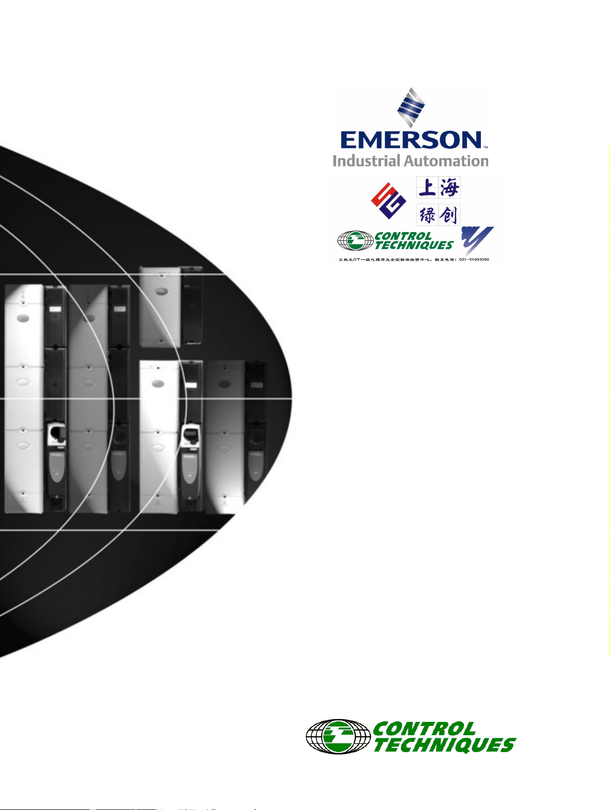
2.1.1 Half controlled SCR/thyristor rectifier (SPMC)
The half controlled SCR/thyristor bridge is used as a front end to the
SPMD inverter module or as a stand alone rectifier for several smaller
drives. Control wiring is linked to the inverter for trip monitoring. Softstart is built in.
SPMC14X2 and 16X1
Figure 2-1 Single half controlled SCR/thyristor
SPMC2X0X
Figure 2-2 Dual half controlled SCR/thyristor
A separate input line reactor (INLXXX) of at least the value
shown in Table 6-2 and Table 6-3 on page 68 must be used
with the rectifiers. Failure to provide sufficient reactance could
damage or reduce the service life of the rectifier or inverter.
The Unidrive SPMC is a half controlled SCR/thyristor bridge and is used
as a front end to the SPMD inverter module or as a stand alone rectifier
for several smaller drives. Soft-start is built in.
The Unidrive SPMU is used as a front end to the SPMD inverter module
or as a stand alone rectifier for several smaller drives. Softstart must be
supplied externally using a resistor and contactor or SPMC.
An external 24V, 3A power supply is required in addition to the AC
supply to allow the rectifier to operate. See section 6.14.3 Unidrive
SPMC/U control connections on page 89 and section 14.1.4 Unidrive
SPM 24V power supply on page 267. Control wiring is required between
the rectifier and motoring drive(s) so that if the rectifier indicates a fault
the motoring drive(s) will be disabled.
The 24V supply must be protected using a 4A slow-blow fuse, one for
each supply pole.
Control connections to the Unidrive SPMC/U should be made with
2
0.5mm
cable.
The status relay contacts are rated for switching non-inductive loads at
250Vac 6A non-inductive, up to 4Adc if the voltage is limited to 40V or up
to 400mA dc if the voltage is limited to 250Vdc. Protection from
overcurrent must be provided.
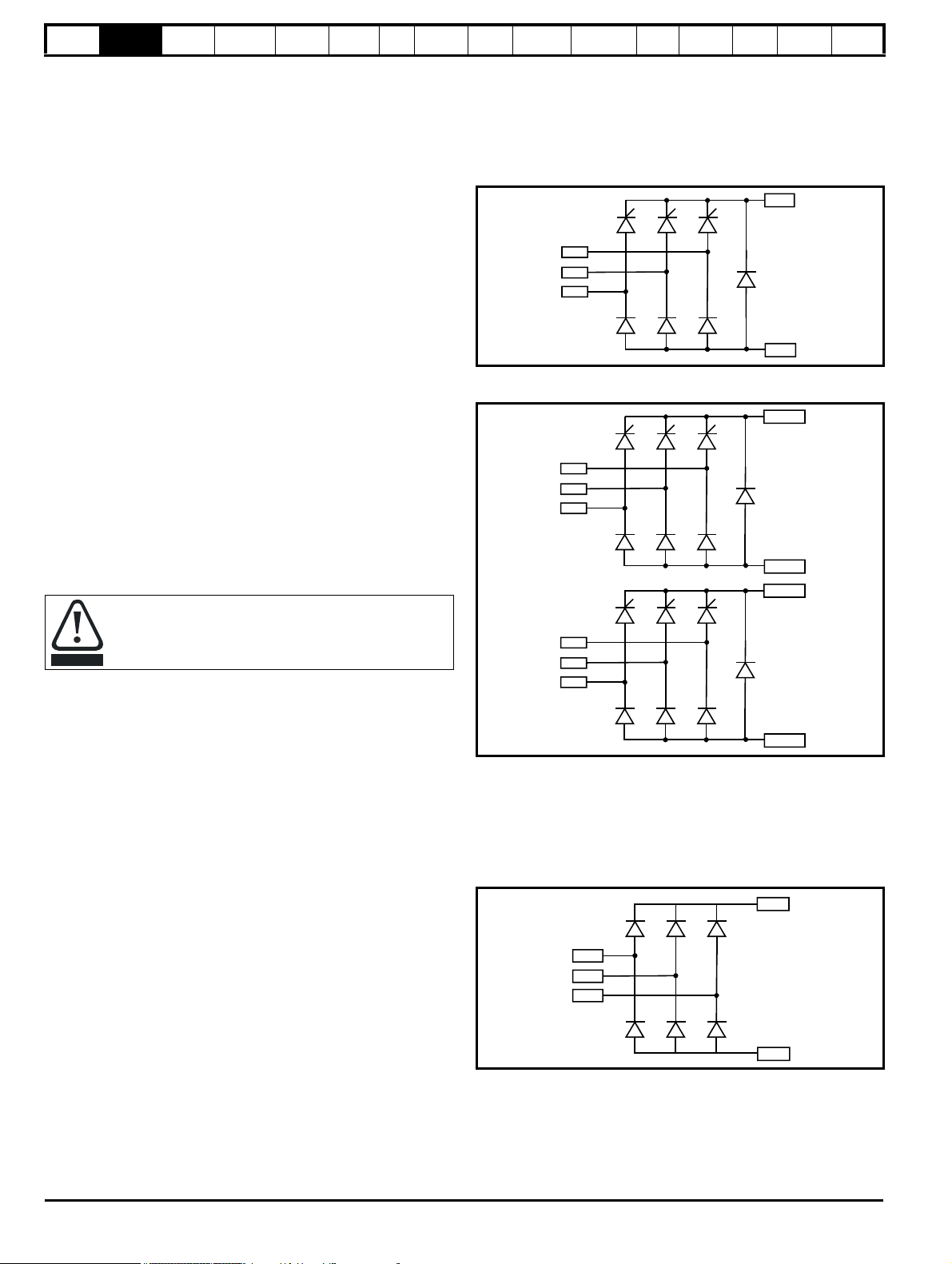
2.1.2 Diode rectifier (SPMU)
The uncontrolled diode rectifier is supplied as an alternative to the half
controlled SCR/thyristor rectifier. Control wiring is limited to a thermal
trip. Soft-start is achieved by the use of an external contactor and
resistor.
SPMU14X2 and 16X1
Figure 2-3 Single diode rectifier
8 Unidrive SPM User Guide
www.controltechniques.com Issue Number: 3
Page 9
Safety
L1A
L2A
L3A
+DC (A)
-DC (A)
L1B
L2B
L3B
+DC (B)
-DC (B)
NOTE
L1
L2
L3
BR
U
V
W
+DC
-DC
Optional
Information
Introduction
Product
Information
System
configuration
Mechanical
Installation
Electrical
Installation
Getting
Star ted
Basic
parameters
Running
the motor
Optimization
SMARTCARD
operation
Onboard
PLC
Advanced
parameters
SPMU24X2 and SPMU26X1
Figure 2-4 Dual diode rectifier
To gain access to the second power stage terminals, the housing covers must be removed. See Figure 5-3 on page 35.
Tec h ni c al
Data
Diagnostics
UL Listing
Information
2.2 SPMA inverter
The SPMA is a complete drive with internal rectifier and AC input line chokes (AC in to AC out). It can provide a maximum continuous output current
of 236A (400V drive). DC connections are available for use in regen and bus-parallel applications. The SPMA is available with or without a braking
IGBT fitted.
Figure 2-5 SPMA inverter schematic
Unidrive SPM User Guide 9
Issue Number: 3 www.controltechniques.com
Page 10
Safety
BR
UVW
+DC
-DC
+DC
Optional
L1
L2
L3
L1A
L2A
L3A
L1
L2
L3
L1A
L2A
L3A
L1B
L2B
L3B
Supply
Drive 1
Drive 2
NOTE
U1
V1
W1
U2
V2
W2
UVW
U1 U2
V1 V2
W1 W2
Drive 1
Drive 2
Information
Introduction
Product
Information
System
configuration
Mechanical
Installation
Electrical
Installation
Getting
Star ted
Basic
parameters
Running
the motor
Optimization
SMARTCARD
operation
Onboard
PLC
Advanced
parameters
Technical
Data
Diagnostics
UL Listing
Information
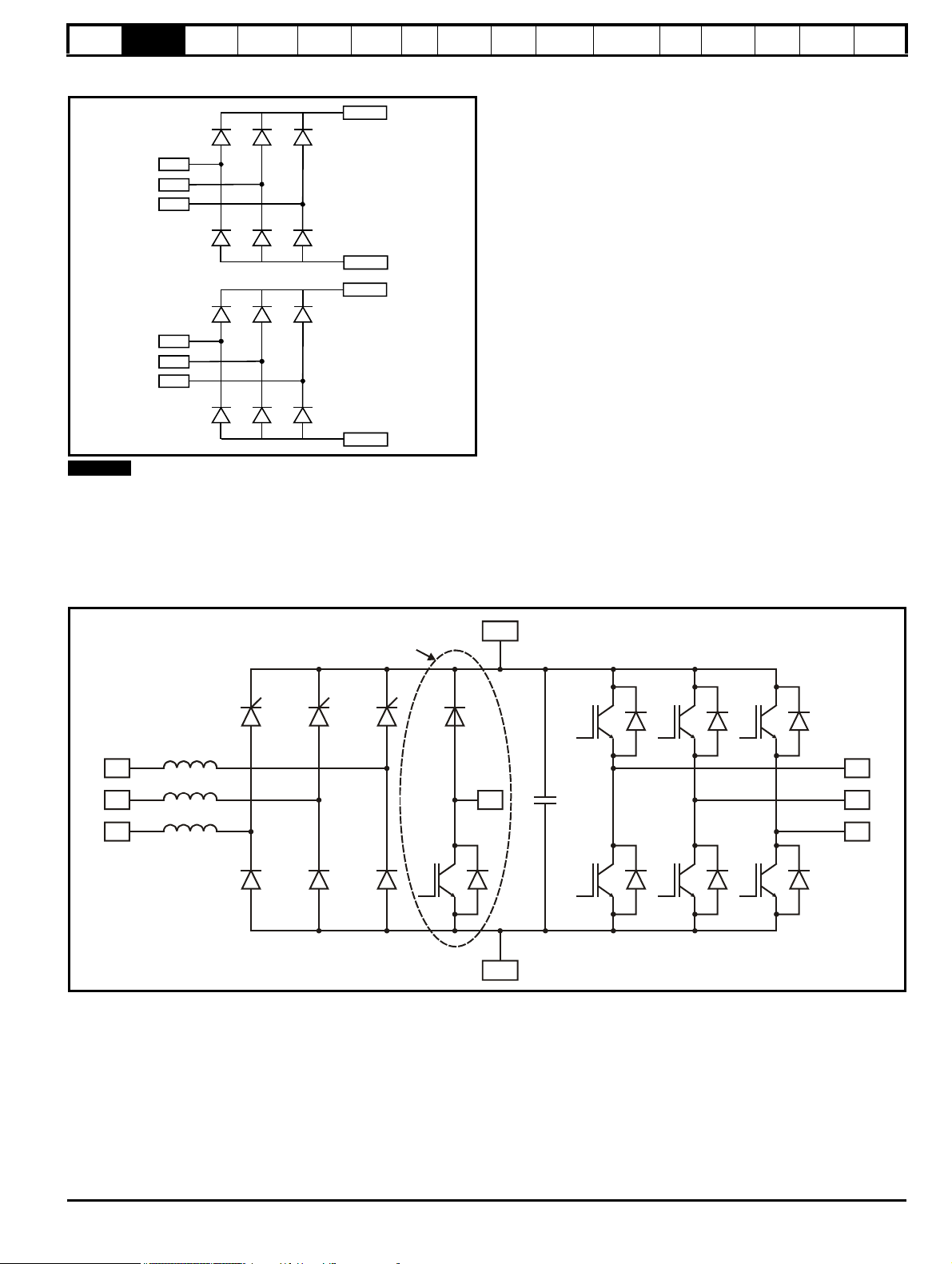
2.3 SPMD inverter
The SPMD is an inverter stage only (DC in to AC out). If a rectifier is required, then an SPMC or SPMU and AC input line reactor must also be
installed. It can provide a maximum continuous output current of 350A (400V drive). DC connections can be used for regen and bus-parallel
applications. The SPMD is available with or without a braking IGBT fitted.
Figure 2-6 SPMA inverter schematic
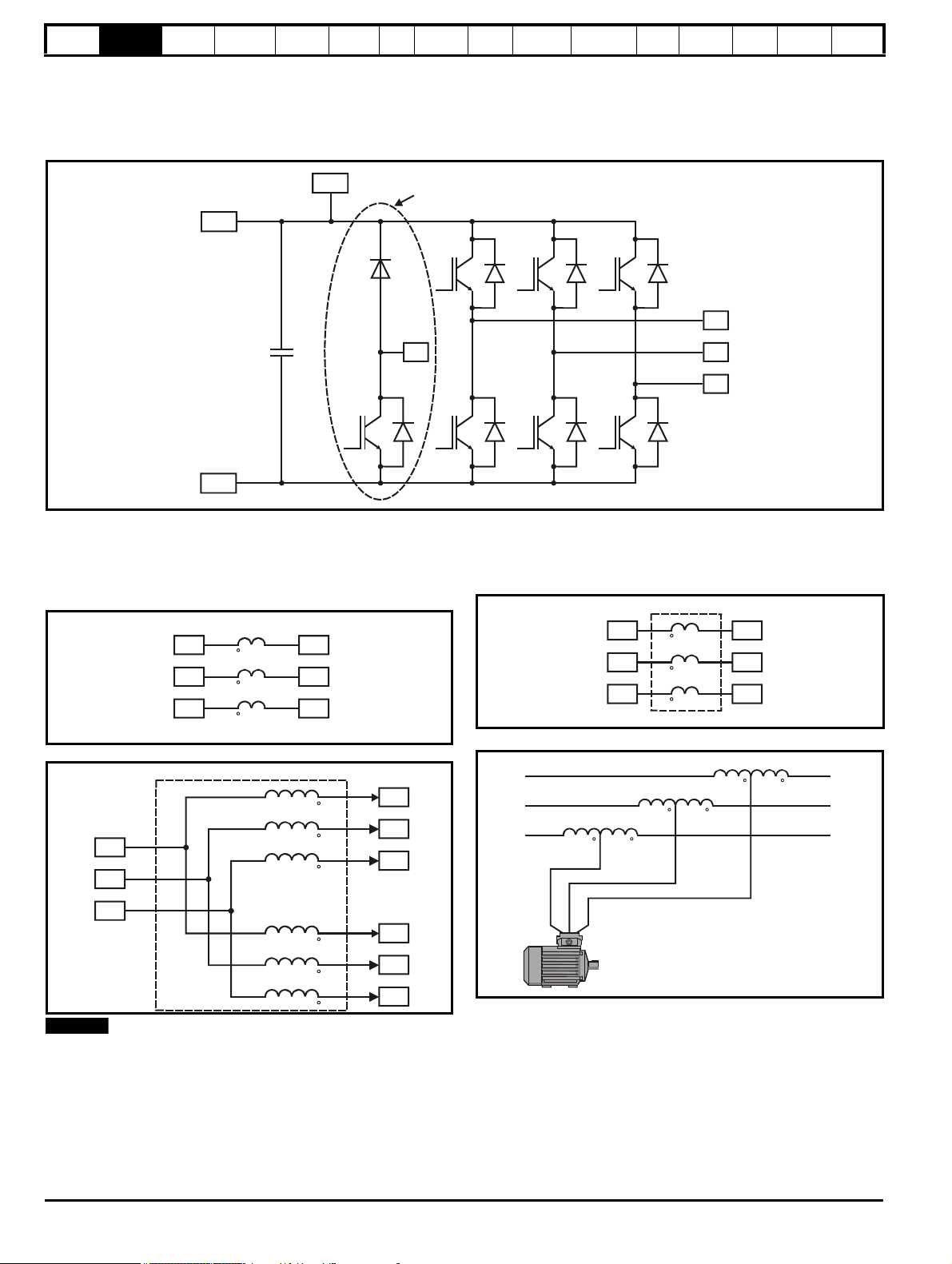
2.4 Input line reactor
The INL line reactor must be used in conjunction with the Unidrive
SPMC/U rectifiers. See section 6.2.2 Input line reactor specifications on
page 67 for further information.
Figure 2-7 Single input line reactor (INLX0X)/force cooled (INLX0XW)
Figure 2-8 Dual input line reactor (INLX1X)
2.5 Output sharing choke
The OTL output sharing choke must be used on the output of Unidrive
SPMA/D when more than one module is paralleled together.
Figure 2-9 Single output sharing choke (OTLX0X)
Figure 2-10 Dual output sharing choke (OTLX1X)
This is not an interbridge reactor.
For a physical representation of the input line reactors and output
sharing chokes, see Figure 3-4 on page 21.
10 Unidrive SPM User Guide
www.controltechniques.com Issue Number: 3
Page 11
Safety
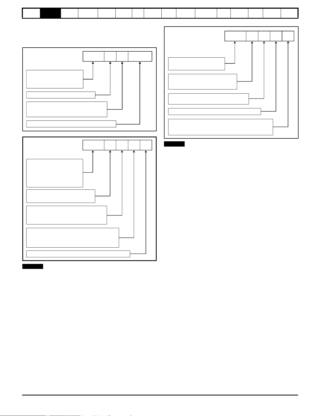
Unidrive SPM product line
SPMC:
Number of rectifier stages
Voltage rating
Current rating step
SPMU:
Uncontrolled rectifier
SPMC 1 402
Controlled rectifier
4: 380V to 480V
6: 500V to 690V
Unidrive SPM product line
SPMA:
SPM frame size
Voltage rating
Configuration
Current rating step
SPMD:
Power module power stages
for custom drive systems DC input
SPMA
1 4 0 1
Power module power stages
for custom drive systems AC input
1: Size 1
2: 200V to 240V (SPMD only)
4: 380V to 480V
6: 500V to 690V
Indicates if an internal brake transistor is fitted:
0: Brake fitted
2: Brake not fitted
NOTE
INL:
Current rating step
OTL:
Output sharing choke
INL
401
Input line reactor
0: Single
1: Dual
Voltage rating
4: 380V to 480V
6: 500V to 690V
W
Single input line reactor type:
Blank:W:Standard copper foil wound
Wirewound
NOTE
Information
Introduction
Product
Information
System
configuration
Mechanical
Installation
Electrical
Installation
Getting
Star ted
parameters
2.6 Model number
The way in which the model numbers for the Unidrive SPM range are
formed is illustrated below.
Figure 2-11 Rectifier (SPMC and SPMU)
Figure 2-12 Drives (SPMA and SPMD)
Basic
Running
the motor
Optimization
SMARTCARD
operation
Onboard
PLC
Advanced
parameters
Tec h ni c al
Data
Figure 2-13 Input line reactor / output sharing choke
The wirewound type of input line reactor is the minimum material
version. Minimum airflow and maximum ambient temperature must be
maintained. Refer to Table 14-24 on page 270.
Diagnostics
UL Listing
Information
200V to 240V SPMD modules can only be supplied by an SPMU or
separate soft start circuit.
Unidrive SPM User Guide 11
Issue Number: 3 www.controltechniques.com
Page 12

Safety
Available output
current
Overload limit -
Heavy Duty
Maximum
continuous
current (above
50% base
speed) -
Normal Duty
Maximum
continuous
current -
Heavy Duty
Motor rated
current set
in the drive
Heavy Duty
- with high
overload capability
Normal Duty
Overload limit -
Normal Duty
NOTE
NOTE
Motor total
current (Pr 4.01)
as a percentage
of motor rated
current
Motor speed as a
percentage of base speed
100%
Max. permissible
continuous
current
100%
I t protection operates in this region
2
70%
50%15%
Pr = 0
Pr = 1
4.25
4.25
Motor total
current (Pr 4.01)
as a percentage
of motor rated
current
Motor speed as a
percentage of base speed
100%
Max. permissible
continuous
current
100%
I t protection operates in this region
2
70%
50%
Pr = 0
Pr = 1
4.25
4.25
Information
Introduction
Product
Information
System
configuration
Mechanical
Installation
Electrical
Installation
Getting
Star ted
Basic
parameters
3 Product Information
3.1 Ratings
The Unidrive SPM is dual rated.
The setting of the motor rated current determines which rating applies Heavy Duty or Normal Duty.
The two ratings are compatible with motors designed to IEC60034.
The graph aside illustrates the difference between Normal Duty and
Heavy Duty with respect to continuous current rating and short term
overload limits.
Running
the motor
Optimization
SMARTCARD
operation
Onboard
PLC
Advanced
parameters
Te ch n ic a l
Data
Diagnostics
UL Listing
Information
Normal Duty Heavy Duty (default)
For applications which use self ventilated (TENV/TEFC) induction
motors and require a low overload capability (e.g. fans, pumps).
Self ventilated (TENV/TEFC) induction motors require increased
protection against overload due to the reduced cooling effect of the fan
at low speed. To provide the correct level of protection the I
operates at a level which is speed dependent. This is illustrated in the
graph below.
The speed at which the low speed protection takes effect can be
changed by the setting of Pr 4.25. The protection starts when the motor
speed is below 15% of base speed when Pr 4.25 = 0 (default) and below
50% when Pr 4.25 = 1.
Operation of motor I2t protection (It.AC trip)
Motor I2t protection is fixed as shown below and is compatible with:
• Self ventilated (TENV/TEFC) induction motors
2
t software
For constant torque applications or applications which require a high
overload capability (e.g. winders, hoists).
The thermal protection is set to protect force ventilated induction motors
and permanent magnet servo motors by default.
N
If the application uses a self ventilated (TENV/TEFC) induction motor
and increased thermal protection is required for speeds below 50% base
speed, then this can be enabled by setting Pr 4.25 = 1.
Motor I2t protection defaults to be compatible with:
• Forced ventilation induction motors
• Permanent magnet servo motors
12 Unidrive SPM User Guide
www.controltechniques.com Issue Number: 3
Page 13

Safety
NOTE
Information
Introduction
Product
Information
System
configuration
Mechanical
Installation
Electrical
Installation
Getting
Star ted
Basic
parameters
Running
the motor
Optimization
SMARTCARD
operation
Onboard
PLC
Advanced
parameters
Technical
Data
Diagnostics
UL Listing
Information
The continuous current ratings given are for maximum 40°C (104°F), 1000m altitude and 3.0 kHz switching. Derating is required for higher switching
frequencies, ambient temperature >40°C (104°F), high altitude and parallel applications. For further information, refer to section 14.1.1 Power and
current ratings (Derating for switching frequency and temperature) on page 263.
Table 3-1 SPMA 400V drive ratings (380V to 480V ±10%)
Normal Duty Heavy Duty
Model
Maximum
continuous
output
current
Peak
current
Nominal
motor
power
at 400V
Nominal
motor
power
at 460V
Maximum
continuous
output
current
Open
loop
peak
current
Closed
loop
peak
current
Nominal
motor
power
at 400V
AAkW hp A AA kW hp A
SPMA14X1 205 225 110 150 180 232 270 90 150
SPMA14X2 236 259 132 200 210 271 315 110 150
Nominal
motor
power
at 460V
External 24V
current
consumption
3.3
Table 3-2 Paralleled SPMA 400V motor drive ratings (380V to 480V ±10%)
Normal Duty Heavy Duty
Required
output
sharing
choke
Paralleled SPMA modules
2 x SPMA14X1
2 x SPMA14X2 448 493 250 400 399 513 598 225 350 1 x OTL412
3 x SPMA14X1 584 642 315 500 513 659 769 280 450 3 x OTL401
3 x SPMA14X2 672 739 355 550 598 769 897 315 500 3 x OTL402
4 x SPMA14X1 779 859 400 650 684 878 1025 355 600 4 x OTL401
4 x SPMA14X2 896 986 500 750 798 1026 1197 400 700 4 x OTL402
5 x SPMA14X1 973 1071 550 850 855 1098 1281 450 750 5 x OTL401
5 x SPMA14X2 1121 1233 600 950 997 1282 1496 550 850 5 x OTL402
6 x SPMA14X1 1168 1285 650 1000 1026 1318 1538 550 900 6 x OTL401
6 x SPMA14X2 1345 1479 750 1150 1197 1539 1795 650 1050 6 x OTL402
Maximum
continuous
output
current
Peak
current
Nominal
motor
power at
400V
Nominal
motor
power at 460V
Maximum
continuous
output
current
Open
loop peak
current
Closed
loop peak
current
Nominal
motor
power
at 400V
Nominal
motor
power at 460V
AAkW hp A AAkW hp
389 428 225 300 342 439 512 185 300 1 x OTL411
When connecting drives in parallel they must be derated. Table 3-2, Table 3-4, Table 3-6, Table 3-8 and Table 3-10 have already the
required de-rating.
Table 3-3 SPMA 690V drive ratings (500V to 690V ±10%)
Model
SPMA16X1
SPMA16X2
Normal Duty Heavy Duty
Maximum
continuous
output
current
Peak
current
Nominal
motor
power
at 690V
Nominal
motor
power
at 575V
Maximum
continuous
output
current
Open
loop
peak
current
Closed
loop
peak
current
Nominal
motor
power
at 690V
Nominal
motor
power
at 575V
AAkW hp A AA kW hp A
125 137 110 125 100 128 149 90 100
144 158 132 150 125 160 187 110 125
External 24V
current
consumption
3.3
Unidrive SPM User Guide 13
Issue Number: 3 www.controltechniques.com
Page 14

Safety
NOTE
CAUTION
NOTE
Information
Introduction
Product
Information
System
configuration
Mechanical
Installation
Electrical
Installation
Getting
Star ted
Basic
parameters
Running
the motor
Optimization
SMARTCARD
operation
Onboard
PLC
Advanced
parameters
Te ch n ic a l
Data
Diagnostics
UL Listing
Information
Table 3-4 Paralleled SPMA 690V motor drive ratings (500V to 690V ±10%)
Normal Duty Heavy Duty
Paralleled SPMA modules
2 x SPMA16X1 237 261 250 250 190 244 284 200 200 1 x OTL611
2 x SPMA16X2 273 300 280 300 237 305 356 250 250 1 x OTL612
3 x SPMA16X1 356 391 355 400 285 366 427 300 300 3 x OTL601
3 x SPMA16X2 410 451 450 450 356 457 534 355 400 3 x OTL602
4 x SPMA16X1 475 522 500 500 380 488 569 400 400 4 x OTL601
4 x SPMA16X2 547 601 560 600 475 610 712 500 500 4 x OTL602
5 x SPMA16X1 593 653 610 600 475 610 712 500 500 5 x OTL601
5 x SPMA16X2 684 752 710 700 593 763 890 610 600 5 x OTL602
6 x SPMA16X1 712 783 710 800 570 732 854 610 600 6 x OTL601
6 x SPMA16X2 820 902 875 900 712 915 1068 710 800 6 x OTL602
Maximum
continuous
output
current
AAkWhp AAAkWhp
Peak
current
Nominal
motor
power
at 690V
Nominal
motor
power
at 575V
Maximum
continuous
output
current
Open
loop
peak
current
Closed
loop
peak
current
Nominal
motor
power
at 690V
Nominal
motor
power
at 575V
Required
output sharing
choke
The Unidrive SPMD can be connected to its rectifier module in two ways, directly above the inverter (docked) or independently mounted in
different vertical planes (undocked). Changes in the flow of air mean that the ratings are different for the two mounting methods for SPMD12x4.
For details on docking, refer to section 5.6 Docking a Unidrive SPMC/U to an SPMD on page 39.
Table 3-5 SPMD 200V drive ratings (200V to 240V ±10%) based on AC supply voltage
Normal Duty Heavy Duty
Maximum
Model
SPMD12X1* 192 211 55 75 156 201 234 45 60
SPMD12X2* 248 272 75 100 192 247 288 55 75
SPMD12X3* 312 343 90 125 250 322 375 75 100
SPMD12X4** 335 365 90 125 290 374 435 90 125
SPMD12X4*** 350 385 110 150 290 374 435 90 125
continuous
output
current
current
AAkWhpA AAkWhp
Peak
Nominal
motor
power at
230V
Nominal
motor
power at
230V
Maximum
continuous
output
current
Open
loop
peak
current
Closed
loop
peak
current
Nominal
motor
power
at 230V
Nominal
motor
power at
230V
Required
rectifier
1 x
SPMU1402
Required
input line
reactor
INL401
INL402
1 x
1 x
External 24V
current
consumption
A
3.3
*SPMD12X1 to 12X3 ratings apply with the rectifier docked and undocked.
**SPMD12X4 rating with the rectifier docked. The overload rating for the SPMD12X4 is only available if the ambient temperature is 35°C or lower.
***SPMD12X4 rating with the rectifier undocked. The maximum continuous output current and overload rating for the SPMD12X4 is only available if
the ambient temperature is 35°C or lower.
When using an SPMU a separate soft start circuit must be
provided for the DC bus. Refer to Figure 4-6 on page 30 and
section 6.5 Resistor sizing for Unidrive SPMU softstart on
page 70.
Table 3-6 Paralleled SPMD 200V motor drive ratings (200V to 240V ±10%) based on AC supply voltage
Normal Duty Heavy Duty
Paralleled SPMD modules
2 x SPMD12X1
2 x SPMD12X2
2 x SPMD12X3
2 x SPMD12X4
Maximum
continuous
output
current
current
AAkWhp AAAkWhp
364 401 110 150 296 381 444 90 125
471 518 132 200 364 468 546 110 150 1 x INL411
592 652 160 250 475 610 712 150 200
636 700 200 250 551 708 826 160 200
Peak
Nominal
motor
power at
230V
Nominal
motor
power at
230V
Maximum
continuous
output
current
Open
loop
peak
current
Closed
loop
peak
current
Nominal
motor
power
at 230V
Nominal
motor
power at
230V
Required
rectifier
1 x
SPMU2402
Required
reactor
1 x INL411
INL412
INL412
The Unidrive SPMD can be connected to its rectifier module in two ways, directly above the inverter (docked) or independently mounted in
different vertical planes (undocked). Changes in the flow of air mean that the ratings are different for the two mounting methods for SPMD14x4.
For details on docking, refer to section 5.6 Docking a Unidrive SPMC/U to an SPMD on page 39.
14 Unidrive SPM User Guide
www.controltechniques.com Issue Number: 3
line
1 x
1 x
Required
output
sharing
choke
1 x
OTL411
1 x
OTL412
1 x
OTL413
1 x
OTL414
Page 15

Safety
NOTE
Information
Introduction
Product
Information
System
configuration
Mechanical
Installation
Electrical
Installation
Getting
Star ted
Basic
parameters
Running
the motor
Optimization
SMARTCARD
operation
Onboard
PLC
Advanced
parameters
Technical
Data
Diagnostics
UL Listing
Information
Table 3-7 SPMD 400V motor drive ratings (380V to 480V ±10%) based on AC supply voltage
Normal Duty Heavy Duty
Maximum
Model
SPMD14X1* 205 225 110 150 180 232 270 90 150
SPMD14X2* 246 270 132 200 210 271 315 110 150
SPMD14X3* 290 319 160 250 246 310 359 132 200
SPMD14X4***
continuous
output
current
AAkWhp AAAkWhp
350 385 200 300 290 374 435 160 250
Peak
current
Nominal
motor
power at
400V
Nominal
motor
power at
460V
Maximum
continuous
output
current
Open
loop
peak
current
Closed
loop
peak
current
Nominal
motor
power
at 400V
Nominal
motor
power at
460V
Required
rectifier
1 x
SPMC1402
Required
input line
reactor
1 x INL401 3.3
1 x INL402 4.5SPMD14X4** 335 365 185 300 290 374 435 160 250
External 24V
current
consumption
A
*SPMD14X1 to 14X3 ratings apply with the rectifier docked and undocked.
**SPMD14X4 rating with the rectifier docked. The overload rating for the SPMD14X4 is only available if the ambient temperature is 35°C or lower.
***SPMD14X4 rating with the rectifier undocked. The maximum continuous output current and overload rating for the SPMD14X4 is only available if
the ambient temperature is 35°C or lower.
Table 3-8 Paralleled SPMD 400V motor drive ratings (380V to 480V ±10%) based on AC supply voltage
Normal Duty Heavy Duty
Paralleled SPMD modules
2 x SPMD14X1 389 428 225 300 342 439 512 185 300
2 x SPMD14X2 467 514 280 400 399 513 598 225 300 1 x OTL412
2 x SPMD14X3 551 606 315 450 467 586 683 280 400
2 x SPMD14X4 636 700 355 500 551 708 826 315 450 1 x OTL414
3 x SPMD14X2 701 771 400 600 598 769 897 315 500
4 x SPMD14X1 779 856 450 650 684 878 1025 355 600 2 x SPMC2402 2 x INL411 4 x OTL401
3 x SPMD14X3 826 909 450 700 701 879 1025 400 650
4 x SPMD14X2 934 1028 500 800 798 1026 1197 450 700 2 x SPMC2402 2 x INL411 4 x OTL402
3 x SPMD14X4 954 1050 560 800 826 1062 1239 450 750
4 x SPMD14X3 1102 1212 630 900 934 1172 1367 550 800
4 x SPMD14X4 1272 1400 710 1000 1102 1416 1652 630 900 2 x INL412 4 x OTL404
Maximum
continuous
output
current
400V
Nominal
motor
power at
460V
Maximum
continuous
output
current
current
AAkWhp A AAkWhp
Peak
Nominal
motor
power at
Open
loop
peak
current
loop
peak
current
at 400V
Nominal
Closed
motor
power
Nominal
motor
power at
460V
Required
rectifier
1 x SPMC2402
1 x SPMC2402 +
1 x SPMC1402
1 x SPMC2402 +
1 x SPMC1402
1 x SPMC1402 +
1 x SPMC2402
2 x SPMC2402
Required
input line
reactor
1 x INL411
1 x INL412
1 x INL411 +
1 x INL401
1 x INL412 +
1 x INL402
1 x INL412 +
1 x INL402
2 x INL412 4 x OTL403
Required
output
sharing
choke
1 x OTL411
1 x OTL413
3 x OTL402
3 x OTL403
3 x OTL404
When connecting drives in parallel they must be derated. Table 3-2, Table 3-4, Table 3-6, Table 3-8 and Table 3-10 have already the
required de-rating.
Table 3-9 SPMD 690V motor drive ratings (500V to 690V ±10%)
Normal Duty Heavy Duty
Maximum
Model
SPMD16X1 125 137 110 125 100 129 150 90 100
SPMD16X2 144 158 132 150 125 161 188 110 125
SPMD16X3 168 184 160 150 144 185 216 132 150
SPMD16X4 192 211 160 200 168 216 252 150 150
continuous
output
current
AAkW
Peak
current
Nominal
motor
power
at 690V
Nominal
motor
power
at 575V
hp
Maximum
continuous
output
current
AAAkW
Open
loop
peak
current
Closed
loop
peak
current
Nominal
motor
power
at 690V
Nominal
motor
power
at 575V
Required
rectifier
Required
input line
reactor
hp A
1 x INL601 3.3
1 x
SPMC/U1601
1 x INL602 4.5
External 24V
current
consumption
Unidrive SPM User Guide 15
Issue Number: 3 www.controltechniques.com
Page 16

Safety
NOTE
NOTE
Information
Introduction
Product
Information
System
configuration
Mechanical
Installation
Electrical
Installation
Getting
Star ted
Basic
parameters
Running
the motor
Optimization
SMARTCARD
operation
Onboard
PLC
Table 3-10 Paralleled SPMD 690V motor drive ratings (500V to 690V ±10%) based on AC supply voltage
Normal Duty Heavy Duty
Paralleled SPMD modules
2 x SPMD16X1 237 261 250 250 190 244 284 200 200
2 x SPMD16X2 273 300 280 300 237 305 356 250 250 1 x OTL612
2 x SPMD16X3 319 351 315 350 273 351 410 250 300
2 x SPMD16X4 364 401 315 350 319 410 478 280 350 2 x SPMC1601 1 x OTL614
3 x SPMD16X2 410 451 450 450 356 457 534 355 400
3 x SPMD16X3 478 526 500 500 410 527 615 450 450
3 x SPMD16X4 547 601 545 600 478 615 718 450 500 3 x SPMC1601 3 x OTL604
4 x SPMD16X3 638 702 630 700 547 703 820 545 600 2 x SPMC2601
4 x SPMD16X4 729 802 710 800 638 820 957 630 700 4 x SPMC1601 4 x OTL604
Maximum
continuous
output
current
A AkW hp A AAkWhp
Peak
current
Nominal
motor
power at
690V
Nominal
motor
power at
575V
Maximum
continuous
output
current
Open
loop
peak
current
Closed
loop
peak
current
Nominal
motor
power
at 690V
Nominal
motor
power at
575V
When connecting drives in parallel they must be derated. Table 3-2, Table 3-4, Table 3-6, Table 3-8 and Table 3-10 have already the
required de-rating.
Table 3-11 Unidrive SPMC/U 400V ratings
External 24V
current
consumption
Model
Maximum
AC input current
AAA
Maximum DC
output current
Advanced
parameters
1 x SPMC2601
1 x SPMC2601
1 x SPMC1601
Required
rectifier
+
Te ch n ic a l
Diagnostics
Data
Required
input line
reactor
1 x INL611
1 x INL612
1 x INL611 +
1 x INL601
1 x INL612 +
1 x INL602
2 x INL612
UL Listing
Information
Required
output
sharing
choke
1 x OTL611
1 x OTL613
3 x OTL602
3 x OTL603
4 x OTL603
SPMC/U1402
SPMC/U2402
344 379
3.0
2 x 312 2 x 345
Table 3-12 Unidrive SPMC/U 690V ratings
External 24V
current
consumption
3.0
Model
SPMC/U1601 195
SPMC/U2601 2 x 173
Maximum AC input
current
AAA
Maximum DC
output current
209
2 x 185
3.1.1 Typical short term overload limits
The maximum percentage overload limit changes depending on the selected motor. Variations in motor rated current, motor power factor and motor
leakage inductance all result in changes in the maximum possible overload. The exact value for a specific motor can be calculated using the
equations detailed in Menu 4 in the Unidrive SP Advanced User Guide.
Typical values are shown in the tables below for closed loop vector (VT) and open loop (OL) modes.
Table 3-13 Typical overload limits for all Unidrive SPM modules
Operating mode
Normal Duty overload with motor rated current = drive rated current 110% for 165s 110% for 9s 110% for 165s 110% for 9s
Heavy Duty overload with motor rated current = drive rated current 150% for 60s 150% for 8s 129% for 97s 129% for 15s
Closed loop/RFC/
Servo/Regen from cold
Closed loop/RFC/Servo/
Regen from 100%
Open loop from cold Open loop from 100%
Generally the drive rated current is higher than the matching motor rated current allowing a higher level of overload than the default setting.
The time allowed in the overload region is proportionally reduced at very low output frequency on some drive ratings.
The maximum overload level which can be attained is independent of the speed.
16 Unidrive SPM User Guide
www.controltechniques.com Issue Number: 3
Page 17

Safety
Information
Introduction
Product
Information
System
configuration
Mechanical
Installation
Electrical
Installation
Getting
Star ted
Basic
parameters
3.2 Operating modes
The Unidrive SPM is designed to operate in any of the following modes:
1. Open loop mode
Open loop vector
Fixed V/F mode (V/Hz)
Quadratic V/F mode (V/Hz)
2. RFC mode
3. Closed loop vector
4. Servo
5. Regen
3.2.1 Open loop mode
For use with induction motors.
The drive applies power to the motor at frequencies varied by the user.
The motor speed is a result of the output frequency of the drive and slip
due to the mechanical load. The drive can improve the speed control of
the motor by applying slip compensation. The performance at low speed
depends on whether V/F mode or open loop vector mode is selected.
Open loop vector mode
The voltage applied to the motor is directly proportional to the frequency
except at low speed where the drive uses motor parameters to apply the
correct voltage to keep the flux constant under varying load conditions.
Typically 100% torque is available down to 1Hz for a 50Hz motor.
For further details refer to section 10.1.1 Open loop motor control on
page 136.
Fixed V/F mode
The voltage applied to the motor is directly proportional to the frequency
except at low speed where a voltage boost is provided which is set by
the user. This mode can be used for multi-motor applications.
Typically 100% torque is available down to 4Hz for a 50Hz motor.
Quadratic V/F mode
The voltage applied to the motor is directly proportional to the square of
the frequency except at low speed where a voltage boost is provided
which is set by the user. This mode can be used for running fan or pump
applications with quadratic load characteristics or for multi-motor
applications. This mode is not suitable for applications requiring a high
starting torque.
3.2.2 RFC mode
Rotor flux control provides closed loop control without the need for
position feedback by using current, voltages and key motor parameters
to estimate the motor speed. It can eliminate instability traditionally
associated with open loop control such as operating large motors with
light loads at low frequencies.
For further details refer to section 10.1.2 RFC mode on page 138.
3.2.3 Closed loop vector mode
For use with induction motors with a feedback device installed.
The drive directly controls the speed of the motor using the feedback
device to ensure the rotor speed is exactly as demanded. Motor flux is
accurately controlled at all times to provide full torque all the way down
to zero speed.
For further details refer to section 10.1.3 Closed loop vector motor
control on page 141.
Running
the motor
Optimization
SMARTCARD
operation
Onboard
PLC
Advanced
parameters
Technical
Data
Diagnostics
UL Listing
Information
For further details refer to section 10.1.4 Servo motor control on
page 144.
3.2.5 Regen
For use as a regenerative front end for four quadrant operation.
Regen operation allows bi-directional power flow to and from the AC
supply. This provides far greater efficiency levels in applications which
would otherwise dissipate large amounts of energy in the form of heat in
a braking resistor.
The harmonic content of the input current is negligible due to the
sinusoidal nature of the waveform when compared to a conventional
bridge rectifier or SCR/thyristor front end.
See the Unidrive SP Regen Installation Guide for more information
about operation in this mode.
3.3 Compatible encoders
Table 3-14 Encoders compatible with Unidrive SPM
Encoder type Pr 3.38 setting
Quadrature incremental encoders with or without
marker pulse
Quadrature incremental encoders with UVW
commutation signals for absolute position for
permanent magnet motors with or without marker
pulse
Forward / reverse incremental encoders with or
without marker pulse
Forward / reverse incremental encoders with
UVW commutation signals for absolute position
for permanent magnet motors with or without
marker pulse
Frequency and direction incremental encoders
with or without marker pulse
Frequency and direction incremental encoders
with UVW commutation signals for absolute
position for permanent magnet motors with or
without marker pulse
Sincos incremental encoders SC (6)
Heidenhain sincos encoders with Endat comms
for absolute position
Stegmann sincos encoders with Hiperface comms
for absolute position
Sincos encoders with SSI comms for absolute
position
SSI encoders (Gray code or binary) SSI (10)
Endat comms only encoders EndAt (8)
UVW commutation only encoders* Ab.SErvo (3)
* This feedback device provides very low resolution feedback and should
not be used for applications requiring a high level of performance
Ab (0)
Ab.SErvo (3)
Fr (2)
Fr.SErvo (5)
Fd (1)
Fd.SErvo (4)
SC.EndAt (9)
SC.HiPEr (7)
SC.SSI (11)
3.2.4 Servo
For use with permanent magnet brushless motors with a feedback
device installed.
The drive directly controls the speed of the motor using the feedback
device to ensure the rotor speed is exactly as demanded. Flux control is
not required because the motor is self excited by the permanent
magnets which form part of the rotor.
Absolute position information is required from the feedback device to
ensure the output voltage is accurately matched to the back EMF of the
motor. Full torque is available all the way down to zero speed.
Unidrive SPM User Guide 17
Issue Number: 3 www.controltechniques.com
Page 18

Safety
Solutions Module
slot 2
SMARTCARD
slot
Keypad
connection
Serial port
connector
Encoder
connection
Control terminals
Solutions Module
slot 1
Solutions Module
slot 3
Rating label
Status LED
Approvals label B
Relay terminals
AC
supply
Internal
EMC filter
DC
supply
Motor
connections
Low voltage DC mode
enable / heatsink fan
supply connections
Brake
resistor
Control master pod Control slave pod
SPMA
Motor
connections
Low voltage DC mode
enable / heatsink fan
supply connections /
rectifier status inputs
Brake
resistor
SPMD
AC
supply
Internal
EMC filter
DC
supply
SPMC/U
Output connections
to slave
Input from Master /
Output to slave
Internal
EMC filter
DC
supply
Internal
EMC filter
DC
supply
AC
supply
AC
supply
DC
output
Status
LEDs
Approvals
label A
Approvals
label A
Rating
label
Status
LED
Cover Base
Control
terminals
NOTE
Information
Introduction
Product
Information
System
configuration
Mechanical
Installation
Electrical
Installation
3.4 Features
Figure 3-1 Features of the Unidrive SPM Modules
Getting
Star ted
Basic
parameters
Running
the motor
Optimization
SMARTCARD
operation
Onboard
PLC
Advanced
parameters
Te ch n ic a l
Data
Diagnostics
UL Listing
Information
24V supply is required for fans on all modules.
18 Unidrive SPM User Guide
www.controltechniques.com Issue Number: 3
Page 19
Safety
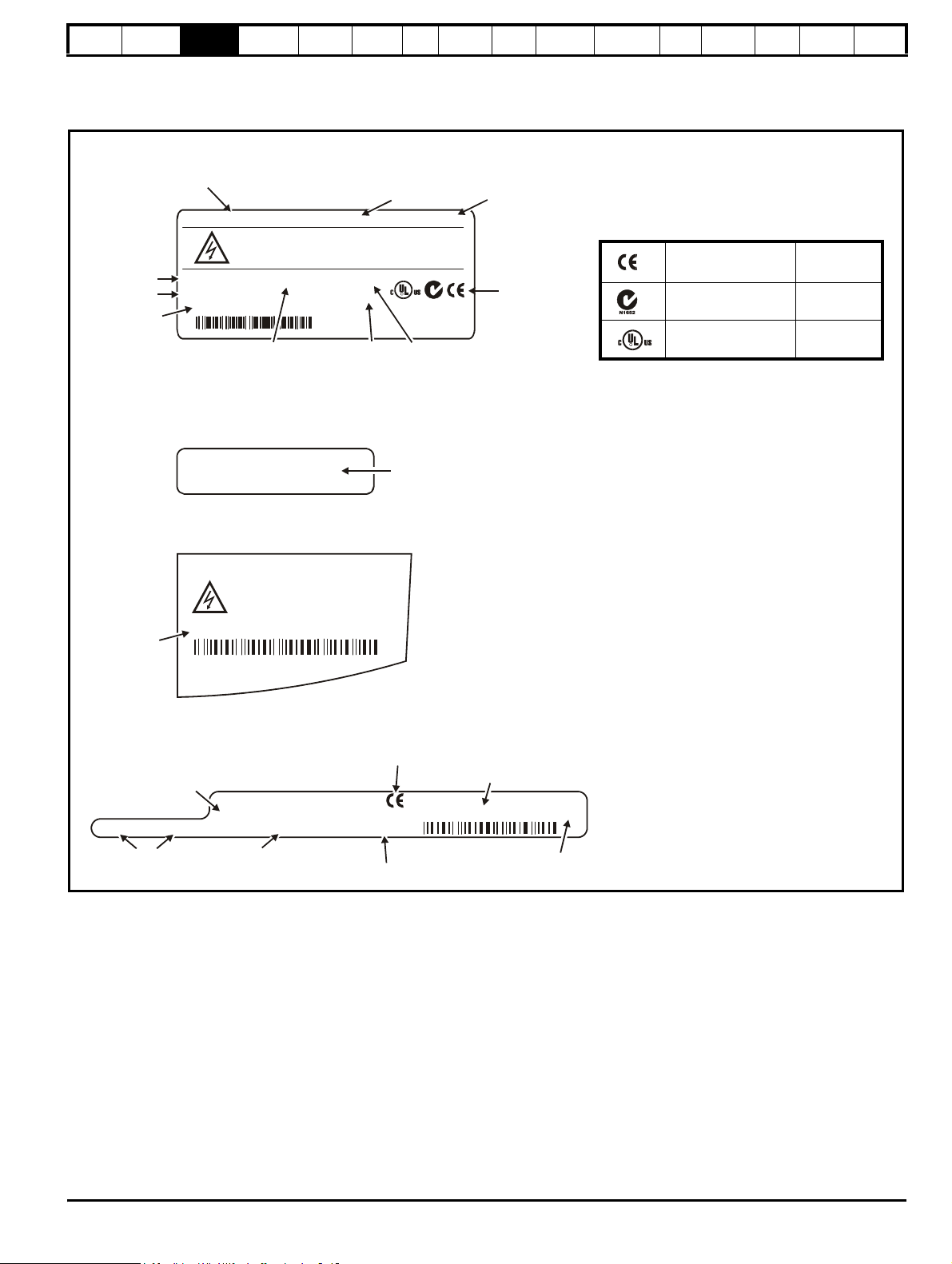
Rating label
(SPMA / SPMD - Master and Slave)
S.No:
3000005001
Serial
number
Please read manual before connecting.
Electric Shock Risk: Wait 10 min between
disconnecting supply & removing covers
Ser No:
3000005001
Serial
number
Approvals label B
(SPMA / SPMD - Master only)
Model
Heavy Duty /
Normal Duty
power rating
Customer and
date code
Approvals
Please read manual before connecting.
SPMA1601 90 / 110kW
STDN39
Electric Shock Risk: Wait 10 min between
disconnecting supply & removing covers
Ser No: 3000005001
Made In U.K
Serial
number
SP 100 TH
Approvals label A
(SPMA / SPMD - Master and Slave)
I/P 500-690V 50-60Hz 3ph 128.0A
O/P 0-690V
100 / 125A
Input voltage
Output voltage
Input
frequency
No. of phases &
Typical input current for
Normal Duty rating
Heavy Duty /
Normal Duty
rating output current
Rectifier rating label
(SPMC / SPMU only)
Status1 Status0
I/P 380-480V 50-60Hz 3ph 204A
O/P 513-648V 219A
SPMC1401
Ser No:
3000005001
STDN39
Customer and
date code
Serial
number
Approvals
Model
Input voltage, frequency,
no. of phases and current
Output voltage and current
Status
LEDs
R
CE approval Europe
C Tick approval Australia
UL / cUL approval
USA &
Canada
R
Key to approvals
Information
Introduction
Product
Information
System
configuration
Mechanical
Installation
Electrical
Installation
Getting
Star ted
Basic
parameters
Running
the motor
3.5 Nameplate description
See Figure 3-1 Features of the Unidrive SPM Modules for location of rating labels.
Figure 3-2 Typical drive rating labels
Optimization
SMARTCARD
operation
Onboard
PLC
Advanced
parameters
Technical
Data
Diagnostics
UL Listing
Information
Unidrive SPM User Guide 19
Issue Number: 3 www.controltechniques.com
Page 20
Safety
WARNING
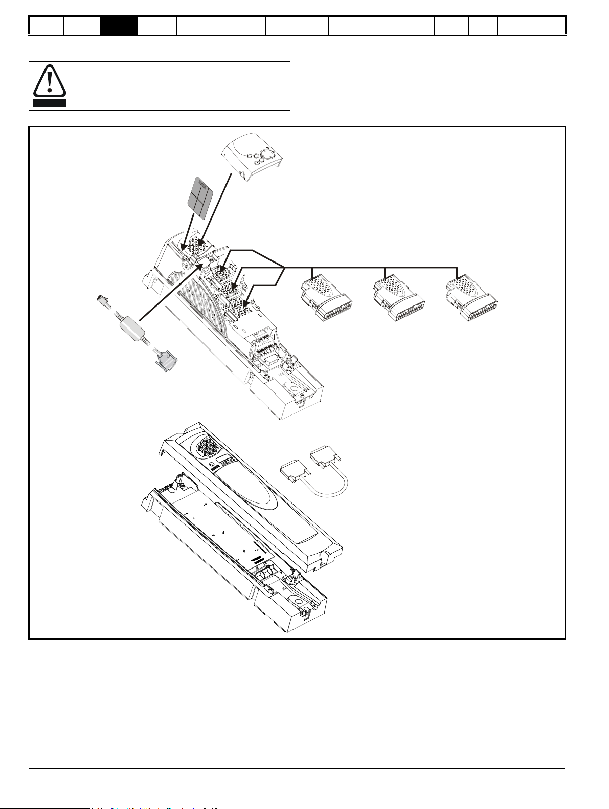
CT Comms
cable
Feedback Automation Fieldbus
Keypad
SMARTCARD*
Paralleling
cable**
Master
interface
Slave
interface
Information
Introduction
Product
Information
System
configuration
Mechanical
Installation
Electrical
Installation
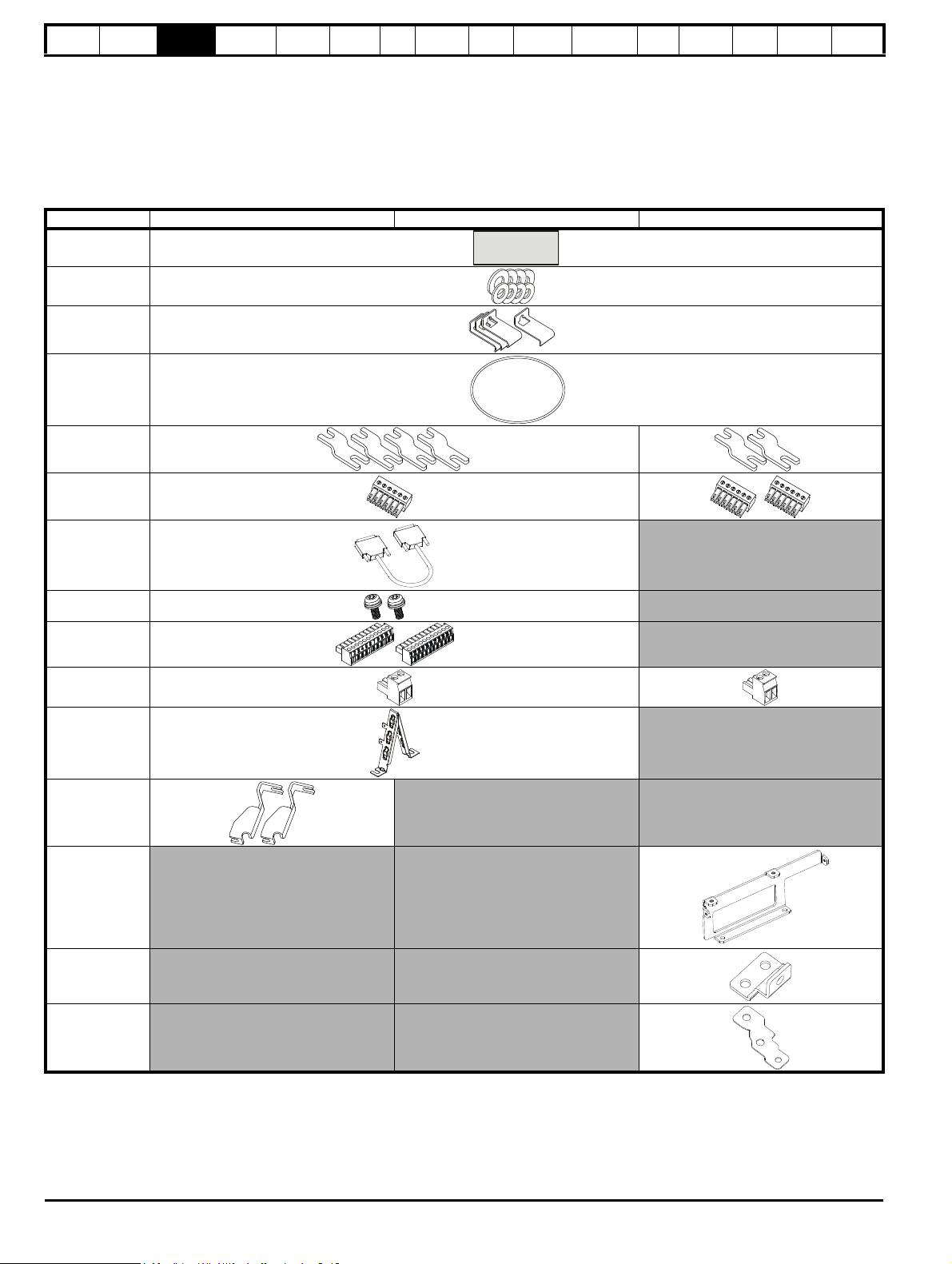
3.6 Options
Power down the drive before installing / removing the
Solutions Module.
Figure 3-3 Control options available with Unidrive SPM
Getting
Star ted
Basic
parameters
Running
the motor
Optimization
SMARTCARD
operation
Onboard
PLC
Advanced
parameters
Te ch n ic a l
Data
Diagnostics
UL Listing
Information
* A SMARTCARD is provided as standard. Only one SMARTCARD can be installed at any one time. For further information, refer to Chapter
11 SMARTCARD operation on page 149.
** Paralleling cable is only supplied with a control slave pod.
20 Unidrive SPM User Guide
www.controltechniques.com Issue Number: 3
Page 21
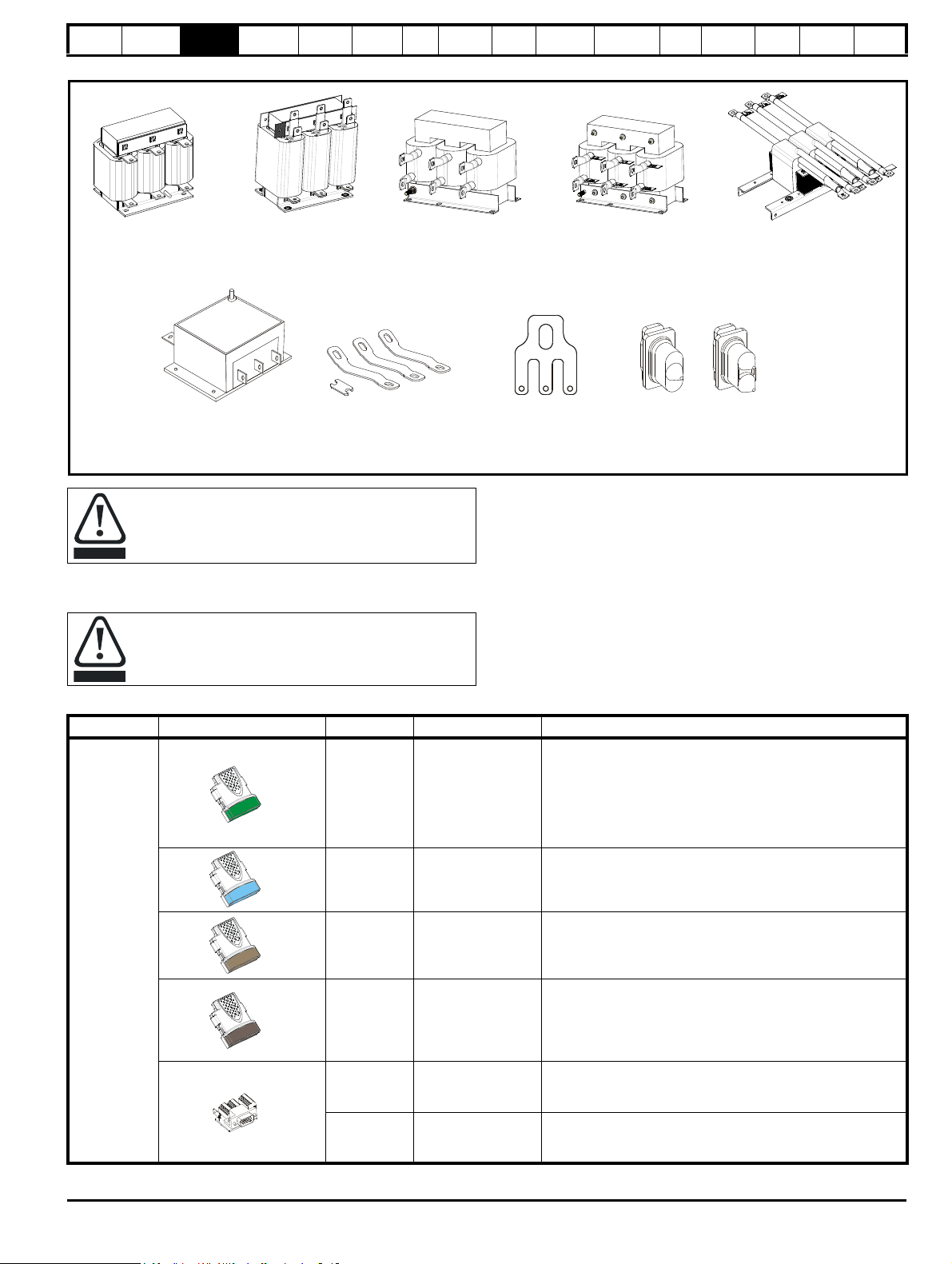
Safety
Single input line reactor
(INLX0X) for use with
Unidrive SPMC/U
Single input line reactor
(INL40XW) for use with
Unidrive SPMC/U
EMC filter
SPMC/U to SPMD
docking kit
3470-0012
Dual output sharing choke
(OTLX1X) for parallel
module drives
Dual input line reactor
(INLX1X) for use with
Unidrive SPMC/U
Single output sharing choke
(OTLX0X) for parallel
module drives
Lifting
bracket
6541-0073
Finger-guard grommets
Single entry
kit of 4
9500-0074
Double entry
kit of 4
9500-0075
CAUTION
CAUTION
Inputs Outputs
• Incremental encoders • Quadrature
• SinCos encoders • Frequency and direction
• SSI encoders • SSI simulated outputs
• EnDat encoders
Information
Introduction
Product
Information
System
configuration
Mechanical
Installation
Electrical
Installation
Figure 3-4 Power options available for Unidrive SPM
Getting
Star ted
Basic
parameters
Running
the motor
Optimization
SMARTCARD
operation
Onboard
PLC
Advanced
parameters
Technical
Data
Diagnostics
UL Listing
Information
All Unidrive SPM Solutions Modules are color-coded in order to make identification easy. The following table shows the color-code key and gives
further details on their function.
Table 3-15 Solutions Module identification
Type Solutions Module Color Name Further Details
Feedback
A separate input line reactor of at least the value shown in
Table 6-2 and Table 6-3 on page 68 must be used with the
rectifiers. Failure to provide sufficient reactance could
damage or reduce the service life of the rectifier or inverter.
Power down the drive before installing / removing the
Solutions Module. Failure to do so may result in damage to
the product.
Light Green
SM-Universal
Encoder Plus
Light Blue SM-Resolver
Brown SM-Encoder Plus
SM-Encoder Output
Plus
15-way D-type
converter
Dark Brown
N/A
Single ended
N/A
encoder interface
(15V)
Universal Feedback interface
Feedback interface for the following devices:
Resolver interface
Feedback interface for resolvers.
Simulated quadrature encoder outputs
Incremental encoder interface
Feedback interface for incremental encoders without
commutation signals.
No simulated encoder outputs available
Incremental encoder interface
Feedback interface for incremental encoders without
commutation signals.
Simulated encoder output for quadrature, frequency and
direction signals
Drive encoder input converter
Provides screw terminal interface for encoder wiring and spade
terminal for shield
Single ended encoder interface
Provides an interface for 15V single ended ABZ or UVW
encoder signals, such as those from hall effect sensors
Unidrive SPM User Guide 21
Issue Number: 3 www.controltechniques.com
Page 22

Safety
• Digital inputs x 3
• Analog output (voltage) x 1
• Digital I/O x 3 • Relay x 2
• Analog inputs (voltage) x 2
Information
Introduction
Product
Information
System
configuration
Mechanical
Installation
Electrical
Installation
Getting
Star ted
Basic
parameters
Running
the motor
Optimization
SMARTCARD
operation
Onboard
PLC
Table 3-15 Solutions Module identification
Type Solutions Module Color Name Further Details
Additional I/O interface
Increases the I/O capability by adding the following to the
Yellow SM-I/O Plus
existing I/O in the drive:
Additional I/O interface
Increase the I/O capability by adding the following to the
Yellow SM-I/O 32
existing I/O in the drive:
• High speed digital I/O x 32
• +24V output
Additional I/O
1 x Analog input (± 10V bi-polar or current modes)
1 x Analog output (0-10V or current modes)
3 x Digital input and 1 x Relay
Additional I/O with real time clock
As per SM-I/O Lite but with the addition of a Real Time Clock
Automation
(I/O
Expansion)
Dark Yellow SM-I/O Lite
Dark Red SM-I/O Timer
for scheduling drive running
Isolated I/O to NAMUR NE37 specifications
For chemical industry applications
Turquoise SM-I/O PELV
1 x Analog input (current modes)
2 x Analog outputs (current modes)
4 x Digital input / outputs, 1 x Digital input, 2 x Relay outputs
Advanced
parameters
Te ch n ic a l
Data
Diagnostics
UL Listing
Information
Automation
(Applications)
Olive SM-I/O 120V
Cobalt Blue
SM-I/O 24V
Protected
Dark Green SM-Applications
White SM-Applications Lite
Dark Blue SM-EZMotion
Moss Green
SM-Applications
Plus
Additional I/O conforming to IEC 61131-2 120Vac
6 digital inputs and 2 relay outputs rated for 120Vac operation
Additional I/O with overvoltage protection up to 48V
2 x Analog outputs (current modes)
4 x Digital input / outputs, 3 x Digital inputs, 2 x Relay outputs
Applications Processor (with CTNet)
nd
2
processor for running pre-defined and /or customer created
application software with CTNet support
Applications Processor
nd
2
processor for running pre-defined and /or customer created
application software
Motion Controller
1
1
/2 axis motion controller with processor for running customer
created application specific software.
Applications Processor (with CTNet)
nd
2
processor for running pre-defined and /or customer created
application software with CTNet support. Enhanced
performance over SM-Applications.
22 Unidrive SPM User Guide
www.controltechniques.com Issue Number: 3
Page 23

Safety
Information
Introduction
Product
Information
System
configuration
Mechanical
Installation
Electrical
Installation
Getting
Star ted
Basic
parameters
Running
the motor
Optimization
SMARTCARD
operation
Onboard
PLC
Table 3-15 Solutions Module identification
Type Solutions Module Color Name Further Details
Advanced
parameters
Technical
Data
Diagnostics
UL Listing
Information
Fieldbus
Purple SM-PROFIBUS-DP
Medium Grey SM-DeviceNet
Dark Grey SM-INTERBUS
Pink SM-CAN
Light Grey SM-CANopen
Red SM-SERCOS
Beige SM-Ethernet
Profibus option
PROFIBUS DP adapter for communications with the drive
DeviceNet option
Devicenet adapter for communications with the drive
Interbus option
Interbus adapter for communications with the drive
CAN option
CAN adapter for communications with the drive
CANopen option
CANopen adapter for communications with the drive
SERCOS option
Class B compliant. Torque velocity and position control modes
supported with data rates (bit/sec): 2MB, 4MB, 8MB and 16MB.
Minimum 250μsec network cycle time. Two digital high speed
probe inputs 1μsec for position capture
Ethernet option
10 base-T / 100 base-T; Supports web pages, SMTP mail and
multiple protocols: DHCP IP addressing; Standard RJ45
connection
Pale Green SM-LON
Brown Red SM-EtherCAT
LonWorks option
LonWorks adapter for communications with the drive
EtherCAT option
EtherCAT adapter for communication with the drive
SLM interface
The SM-SLM allows SLM feedback to be connected directly to
SLM Orange SM-SLM
the Unidrive SP drive and allows operation in either of the
following modes:
• Encoder only mode
• Host mode
Table 3-16 Keypad identification
Type Keypad Name Further Details
SM-Keypad
LED keypad option
Keypad with a LED display
Keypad
SM-Keypad Plus
LCD keypad option
Keypad with an alpha-numeric LCD display with Help function
Table 3-17 Other options
Type Option Name Further Details
Power
supply
24V power supply 24V, 10A power supply (Part No: 8510-0000)
Unidrive SPM User Guide 23
Issue Number: 3 www.controltechniques.com
Page 24
Safety
CAUTION
Risk of Electric Shock
Power down unit 10minutes
before removing cover
M6
M8
M8x20
Information
Introduction
Product
Information
System
configuration
Mechanical
Installation
Electrical
Installation
Getting
Star ted
Basic
parameters
Running
the motor
Optimization
SMARTCARD
operation
Onboard
PLC
Advanced
parameters
Te ch n ic a l
3.7 Items supplied with the drive
The drive is supplied with a copy of the Unidrive SPM User Guide, a
SMARTCARD (control master pod only), the safety booklet, the
certificate of quality, an accessory kit box including the items shown in
Table 3-18, and two CD ROMs. The Unidrive SPM CD ROM contains
information specific to this product, and the standard Unidrive SP CD
ROM contains general documentation and software tools.
Table 3-18 Accessories supplied with Unidrive SPM
Description SPMA SPMD SPMC/U
UL warning label
Nylon washers
Sealing clips
Through panel
mounting gasket
Mounting bracket
Fan / control
connector(s)
Data
Diagnostics
UL Listing
Information
Paralleling cable
Mounting screws
Control
connectors
Relay connector
Grounding
bracket
Top surface
mounting
brackets
Surface
mounting
brackets
Grounding
busbar
Slave only
Master only
Master only
Master only
EMC output
bracket
24 Unidrive SPM User Guide
www.controltechniques.com Issue Number: 3
Page 25
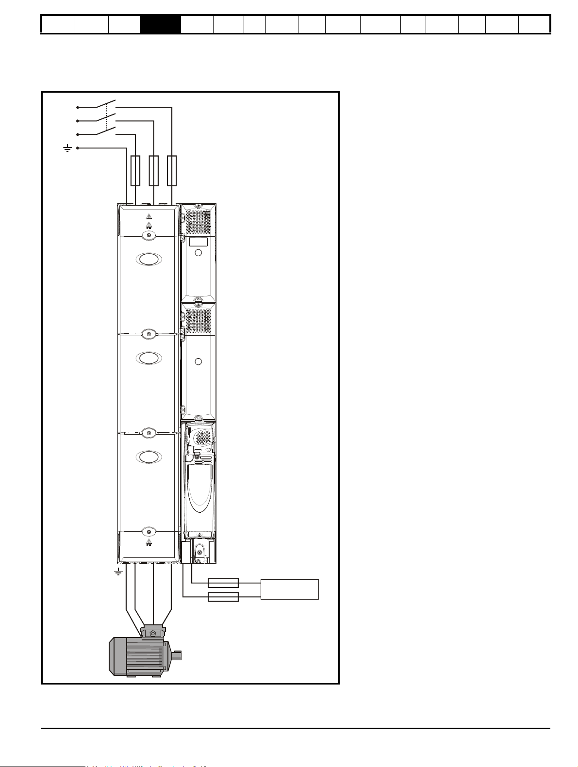
UVW
L3
L2
L1
Fuses*
24Vdc***
Fuses**
Safety
Information
Introduction
Product
Information
System
configuration
Mechanical
Installation
Electrical
Installation
Getting
Star ted
Basic
parameters
Running
the motor
Optimization
SMARTCARD
operation
Onboard
PLC
Advanced
parameters
Te ch n ic a l
Data
Diagnostics
UL Listing
Information
4 System configuration
This chapter demonstrates various Unidrive SPM system configurations. A suitable external 24Vdc power supply is available from the supplier of the
drive. See section 14.1.4 Unidrive SPM 24V power supply on page 267 for further details.
Figure 4-1 Layout for a Unidrive SPMA module operating on a 3-phase AC supply
*Refer to Table 6-15 on page 74 for technical data and part numbers.
**Fuses are needed only if the power supply has a current rating of more than 10A.
***Refer to section 14.1.3 Supply requirements on page 267 for supply requirements.
Unidrive SPM User Guide 25
Issue Number: 3 www.controltechniques.com
Page 26
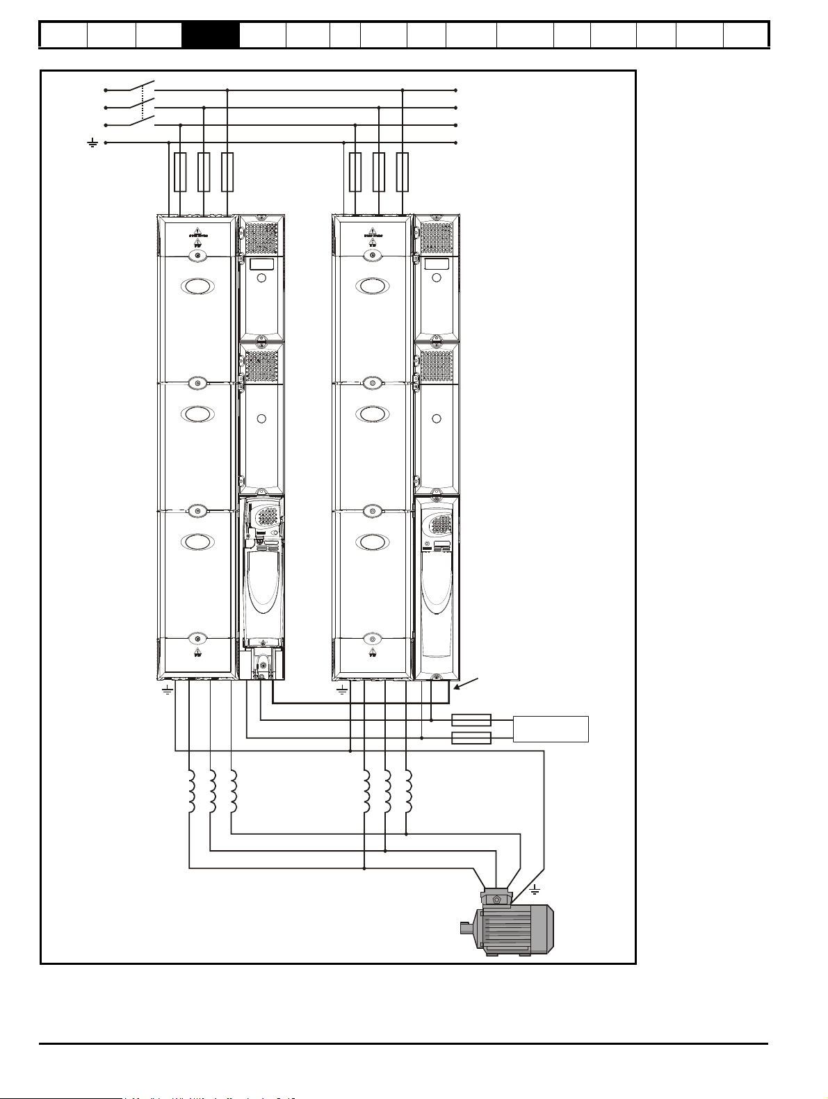
Safety
L3
L2
L1
Fuses* Fuses*
OTLXXX
sharing
chokes
UVW UVW
24Vdc***
Paralleling
cable
OTLXXX
sharing
chokes
Fuses**
Master Slave
Information
Introduction
Product
Information
System
configuration
Mechanical
Installation
Electrical
Installation
Getting
Star ted
Basic
parameters
Running
the motor
Optimization
Figure 4-2 Layout for two or more Unidrive SPMA modules operating on a 3-phase AC supply
SMARTCARD
operation
Onboard
PLC
Advanced
parameters
Technical
Data
Diagnostics
UL Listing
Information
*Refer to Table 6-15 on page 74 for technical data and part numbers.
**Fuses are needed only if the power supply has a current rating of more than 10A.
***Refer to section 14.1.3 Supply requirements on page 267 for supply requirements.
Refer to the external 24V power supply current consumption column in the ratings tables in section 3.1 Ratings on page 12.
26 Unidrive SPM User Guide
www.controltechniques.com Issue Number: 3
Page 27

L3
L2
L1
Fuses*
UVW
+DC -DC
INLXXX
Line reactor***
Rectifier to
inverter
control wiring
Fuses**
Fuses**
SPMC
24Vdc****
SPMD
24Vdc****
Safety
Information
Introduction
Product
Information
System
configuration
Mechanical
Installation
Electrical
Installation
Getting
Star ted
Basic
parameters
Running
the motor
Optimization
Figure 4-3 Layout for an Unidrive SPMD module operating on a 3-phase supply
SMARTCARD
operation
Onboard
PLC
Advanced
parameters
Te ch n ic a l
Data
Diagnostics
UL Listing
Information
*Refer to Table 6-16, Table 6-17 on page 74 and Table 6-18 on page 75 for technical data and part numbers.
**Fuses are needed only if the power supply has a current rating of more than 10A.
***Refer to Table 6-2, Table 6-3, Table 6-4 and Table 6-5 on page 68 for technical data and part numbers.
****Refer to section 14.1.3 Supply requirements on page 267 for supply requirements.
Unidrive SPM User Guide 27
Issue Number: 3 www.controltechniques.com
Page 28

Safety
L3
L2
L1
Fuses*
INLXXX
Line reactor***
UV
W
+DC
-DC
Rectifier to
inverter
control wiring
Fuses**
24V SPMD
enable
24Vdc****
Fuses**
K1
OPEN
CLOSED
K
2
OPEN
CLOSED
3s
Under Voltage
Drive Healthy
3s
Under
voltage
active
Pr
10.16
Switching sequence for K1 and K2
24Vdc****
*Refer to Table 6-16,
Table 6-17 on page 74
and Table 6-18 on
page 75 for technical
data and part numbers.
**Fuses are needed only
if the power supply has a
current rating of more
than 10A.
***Refer to Table 6-2,
Table 6-3, Table 6-4 and
Table 6-5 on page 68 for
technical data and part
numbers.
****Refer to section
14.1.3 Supply
requirements on
page 267 for supply
requirements.
For softstart circuit
component sizing, refer
to section 6.5 Resistor
sizing for Unidrive SPMU
softstart on page 70.
Information
Introduction
Product
Information
System
configuration
Mechanical
Installation
Electrical
Installation
Getting
Star ted
Basic
parameters
Running
the motor
Optimization
SMARTCARD
operation
Onboard
PLC
Advanced
parameters
Technical
Data
Figure 4-4 Layout for an Unidrive SPMD module operating on a 3 phase supply with SPMU (uncontrolled) rectifier and softstart circuit
Diagnostics
UL Listing
Information
28 Unidrive SPM User Guide
www.controltechniques.com Issue Number: 3
Page 29

Master
L3
L2
L1
Fuses* Fuses*
INLXXX
Line reactor**
INLXXX
Line reactor**
OTLXXX
Sharing
chokes
OTLXXX
Sharing
chokes
UVW UVW
+DC -DC +DC -DC
Rectifier
control
connections
Fuses***
Fuses***
SPMC
24Vdc****
SPMD
24Vdc****
Slave
Master/
slave
interface
lead
Rectifier
to inverter
control
wiring
*Refer to Table 6-16, Table 6-17 on
page 74 and Table 6-18 on page 75 for
technical data and part numbers.
**Refer to Table 6-2, Table 6-3, Table 64 and Table 6-5 on page 68 for
technical data and part numbers.
***Fuses are needed only if the power
supply has a current rating of more
than 10A.
****Refer to section 14.1.3 Supply
requirements on page 267 for supply
requirements.
Current sharing between drives
whose motor outputs are
connected in parallel
When used from a 3 phase supply, it is
preferable not to link the DC bus
because the impedance between DC
and each inverter output is just the
impedance of the output chokes. Also,
on the input side, input current sharing
is determined only by making the
temperature of the two rectifiers similar
and by ensuring that both rectifiers see
the same impedance to the line power
supply.
Safety
Information
Introduction
Product
Information
System
configuration
Mechanical
Installation
Electrical
Installation
Getting
Star ted
Basic
parameters
Running
the motor
Optimization
SMARTCARD
operation
Figure 4-5 Layout for two or more Unidrive SPMD modules operating on a 3-phase AC supply
Onboard
PLC
Advanced
parameters
Te ch n ic a l
Data
Diagnostics
UL Listing
Information
Unidrive SPM User Guide 29
Issue Number: 3 www.controltechniques.com
Page 30
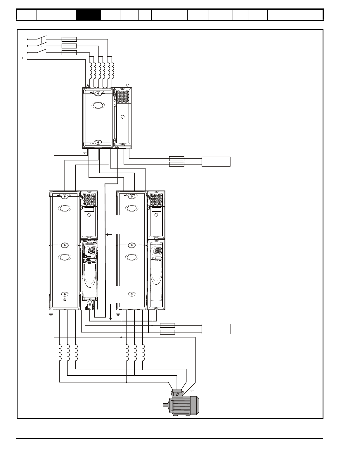
Safety
Master Slave
OTLXXX
Sharing
chokes
OTLXXX
Sharing
chokes
UVW UVW
+DC -DC
Master/
slave
interface
lead
Rectifier
to inverter
control
wiring
Fuses***
Fuses***
L3
L2
L1
Fuses*
INLX1X
Line reactor**
24Vdc****
24Vdc****
*Refer to Table 6-16, Table 6-17 on
page 74 and Table 6-18 on page 75 for
technical data and part numbers.
**Refer to Table 6-2, Table 6-3, Table 6-4
and Table 6-5 on page 68 for technical
data and part numbers.
***Fuses are needed only if the power
supply has a current rating of more than
10A.
****Refer to section 14.1.3 Supply
requirements on page 267 for supply
requirements.
Current sharing between drives
whose motor outputs are
connected in parallel
When used from a 3 phase supply, it is
preferable not to link the DC bus because
the impedance between DC and each
inverter output is just the impedance of
the output chokes. Also, on the input
side, input current sharing is determined
only by making the temperature of the
two rectifiers similar and by ensuring that
both rectifiers see the same impedance
to the line power supply.
Information
Introduction
Product
Information
System
configuration
Mechanical
Installation
Electrical
Installation
Getting
Star ted
Basic
parameters
Running
the motor
Optimization
SMARTCARD
operation
Figure 4-6 Layout for two Unidrive SPMD modules with a dual SPMC rectifier operating on a 3-phase AC supply
Onboard
PLC
Advanced
parameters
Technical
Data
Diagnostics
UL Listing
Information
30 Unidrive SPM User Guide
www.controltechniques.com Issue Number: 3
Page 31

Slave
OTLXXX
Sharing
chokes
OTLXXX
Sharing
chokes
UVW UVW
+DC -DC
Master/
slave
interface
lead
Rectifier
to inverter
control
wiring
Fuses***
Fuses***
L3
L2
L1
Fuses*
INLX1X
Line reactor**
24Vdc****
24Vdc****
Slave
*Refer to Table 6-16, Table 6-17 on
page 74 and Table 6-18 on page 75 for
technical data and part numbers.
**Refer to Table 6-2, Table 6-3, Table 6-4
and Table 6-5 on page 68 for technical
data and part numbers.
***Fuses are needed only if the power
supply has a current rating of more than
10A.
****Refer to section 14.1.3 Supply
requirements on page 267 for supply
requirements.
Current sharing between drives
whose motor outputs are
connected in parallel
When used from a 3 phase supply, it is
preferable not to link the DC bus because
the impedance between DC and each
inverter output is just the impedance of
the output chokes. Also, on the input side,
input current sharing is determined only
by making the temperature of the two
rectifiers similar and by ensuring that both
rectifiers see the same impedance to the
line power supply.
To use the remote mounted control
master pod, all modules in the system
must be slaves. This acts as a master
control unit and connects to the system as
shown.
The remote mounted control master pod
allows the user to place all control circuitry
in one low voltage cabinet and permits up
to a maximum of 10 Unidrive SPMD
modules to be connected in parallel.
Safety
Information
Introduction
Product
Information
System
configuration
Mechanical
Installation
Electrical
Installation
Getting
Star ted
Basic
parameters
Running
the motor
Optimization
SMARTCARD
operation
Onboard
PLC
Advanced
parameters
Te ch n ic a l
Data
Diagnostics
UL Listing
Information
Figure 4-7 Layout for two Unidrive SPMD slave modules with a dual SPMC rectifier operating on a 3-phase AC supply with a remote
mounted control master pod
Unidrive SPM User Guide 31
Issue Number: 3 www.controltechniques.com
Page 32

Safety
Control master pod Control slave pod
Paralleling cable*
Output from
master to slave
Input from
master to slave
Output from slave
to second slave
NOTE
NOTE
Information
Introduction
Product
Information
System
configuration
Mechanical
Parallel control connections
Figure 4-8 Parallel control connections
Installation
Electrical
Installation
Getting
Star ted
Basic
parameters
Running
the motor
Optimization
SMARTCARD
operation
Onboard
PLC
Advanced
parameters
Technical
Data
Diagnostics
UL Listing
Information
*Only supplied with slave drive.
N
The parallel cable should be routed according to the rules shown in
Figure 6-25 Sensitive signal circuit clearance on page 84 for the control
cable.
N
The screw locks on the parallel cable must be fully tightened.
32 Unidrive SPM User Guide
www.controltechniques.com Issue Number: 3
Page 33

Safety
WARNING
WARNING
WARNING
WARNING
WAR NING
Information
Introduction
Product
Information
System
configuration
Mechanical
Installation
Electrical
Installation
Getting
Star ted
Basic
parameters
Running
the motor
Optimization
SMARTCARD
operation
Onboard
PLC
Advanced
parameters
Tec h ni c al
Data
Diagnostics
UL Listing
Information
5 Mechanical Installation
This chapter describes all the mechanical details required to install the
drive. The drive is intended to be installed in an enclosure. Key features
of this chapter include:
• Surface and through-panel mounting
• Remote mounting of control master pod
• Enclosure sizing and layout
• Solutions Module installation
• Terminal location and torque settings
• Docking the Unidrive SPMD and SPMC/U
5.1 Safety information
Follow the instructions
The mechanical and electrical installation instructions must
be adhered to. Any questions or doubt should be referred to
the supplier of the equipment. It is the responsibility of the
owner or user to ensure that the installation of the drive and
any external option unit, and the way in which they are
operated and maintained, comply with the requirements of
the Health and Safety at Work Act in the United Kingdom or
applicable legislation and regulations and codes of practice in
the country in which the equipment is used.
Competence of the installer
The drive must be installed by professional assemblers who
are familiar with the requirements for safety and EMC. The
assembler is responsible for ensuring that the end product or
system complies with all the relevant laws in the country
where it is to be used.
Lifting the drive
The weights of the drives are as follows:
SPMA 80kg (176.4lb)
SPMD 42kg (92.6lb)
SPMC/U20kg (44lb)
Use appropriate safeguards when lifting these models.
5.2 Planning the installation
The following considerations must be made when planning the
installation:
5.2.1 Access
Access must be restricted to authorized personnel only. Safety
regulations which apply at the place of use must be complied with.
The IP (Ingress Protection) rating of the drive is installation dependent.
For further information, please refer to section 5.10 Enclosing drive for
high environmental protection on page 56.
5.2.2 Environmental protection
The drive must be protected from:
• moisture, including dripping water or spraying water and
condensation. An anti-condensation heater may be required, which
must be switched off when the drive is running.
• contamination with electrically conductive material
• contamination with any form of dust which may restrict the fan, or
impair airflow over various components
• temperature beyond the specified operating and storage ranges
• corrosive gasses
5.2.3 Cooling
The heat produced by the drive must be removed without its specified
operating temperature being exceeded. Note that a sealed enclosure
gives much reduced cooling compared with a ventilated one, and may
need to be larger and/or use internal air circulating fans.
For further information, please refer to section 5.8.4 Enclosure sizing on
page 51.
5.2.4 Electrical safety
The installation must be safe under normal and fault conditions.
Electrical installation instructions are given in Chapter 6 Electrical
Installation on page 64.
5.2.5 Fire protection
The drive enclosure is not classified as a fire enclosure. A separate fire
enclosure must be provided.
5.2.6 Electromagnetic compatibility
Variable speed drives are powerful electronic circuits which can cause
electromagnetic interference if not installed correctly with careful
attention to the layout of the wiring.
Some simple routine precautions can prevent disturbance to typical
industrial control equipment.
If it is necessary to meet strict emission limits, or if it is known that
electromagnetically sensitive equipment is located nearby, then full
precautions must be observed. In-built into the drive, is an internal EMC
filter, which reduces emissions under certain conditions. If these
conditions are exceeded, then the use of an external EMC filter may be
required at the drive inputs, which must be located very close to the
drives. Space must be made available for the filters and allowance made
for carefully segregated wiring. Both levels of precautions are covered in
section 6.13 EMC (Electromagnetic compatibility) on page 79.
5.2.7 Hazardous areas
The drive must not be located in a classified hazardous area unless it is
installed in an approved enclosure and the installation is certified.
5.3 Terminal cover removal
Isolation device
The AC supply must be disconnected from the drive using an
approved isolation device before any cover is removed from
the drive or before any servicing work is performed.
Stored charge
The drive contains capacitors that remain charged to a
potentially lethal voltage after the AC supply has been
disconnected. If the drive has been energized, the AC
supply must be isolated at least ten minutes before work
may continue.
Normally, the capacitors are discharged by an internal
resistor. Under certain, unusual fault conditions, it is possible
that the capacitors may fail to discharge, or be prevented
from being discharged by a voltage applied to the output
terminals. If the drive has failed in a manner that causes the
display to go blank immediately, it is possible the capacitors
will not be discharged. In this case, consult Control
Techniques or their authorized distributor.
5.3.1 Removing the terminal covers
Unidrive SPMA and SPMD are fitted with three terminal covers: Control,
input and output terminal covers.
Unidrive SPM/C are fitted with two terminal covers: Input and output
terminal covers. For the dual SPMC/U rectifier, the terminal covers and
housing must be removed to gain access to all the terminals.
Unidrive SPM User Guide 33
Issue Number: 3 www.controltechniques.com
Page 34

Safety
ControlOutput
Input
SPMA
SPMD
SPMC/U
Control
Output
Input
Input
Output
Information
Introduction
Product
Information
System
configuration
Mechanical
Installation
Electrical
Installation
Getting
Star ted
Figure 5-1 Location and identification of terminal covers
Basic
parameters
Running
the motor
Optimization
SMARTCARD
operation
Onboard
PLC
Advanced
parameters
Technical
Data
Diagnostics
UL Listing
Information
34 Unidrive SPM User Guide
www.controltechniques.com Issue Number: 3
Page 35

Safety
Pozi Pz2
Pozi Pz2
T25 Torx
T25 Torx
Information
Introduction
Product
Information
System
configuration
Mechanical
Installation
Electrical
Installation
Getting
Star ted
Basic
parameters
Running
the motor
Optimization
SMARTCARD
operation
Onboard
PLC
To remove a terminal cover, undo the screw and lift the terminal cover off as shown.
When replacing the terminal covers the screws should be tightened with a maximum torque of 1 N m (0.7 lb ft).
Figure 5-2 Removing the terminal covers (Uni SPMA illustrated)
Advanced
parameters
Tec h ni c al
Data
Diagnostics
UL Listing
Information
Figure 5-3 Removing the Unidrive SPMC/U dual rectifier terminal covers and housing
When removing the Unidrive SPMC/U dual rectifier centre housing, undo the 3 x T25 torx head screws as shown in Figure 5-3. When the housing is
replaced, the screws should be tightened with a maximum torque of 2.5 N m (1.8 lb ft).
Unidrive SPM User Guide 35
Issue Number: 3 www.controltechniques.com
Page 36

Safety
1 2
All models
1 2
SPMA and
SPMD
NOTE
Single cable entry grommet
Double cable entry grommet
WARNING
NOTE
Information
Introduction
Product
Information
System
configuration
Mechanical
Installation
Electrical
Installation
Getting
Star ted
parameters
5.3.2 Removing the finger-guard and DC terminal cover break-outs
Figure 5-4 Removing the finger-guard break-outs
Basic
Running
the motor
Optimization
SMARTCARD
operation
Onboard
PLC
Advanced
parameters
Technical
Data
Diagnostics
UL Listing
Information
Place finger-guard on a flat solid surface and hit relevant break-outs with
hammer as shown (1). Continue until all required break-outs are
removed (2). Remove any flash / sharp edges once the break-outs are
removed.
Grommets are available for the Unidrive SPM finger-guards. Two
versions are available allowing for either single or double cable entries.
N
These grommets are required to meet IP20 when installed in an open
environment.
Figure 5-5 Unidrive SPM finger-guard grommets
The grommets are available as a kit of four grommets under the
following part numbers:
9500-0074 Kit of four single entry grommets
9500-0075 Kit of four double entry grommets
The drive must not be run without the finger guards and
grommets installed because In the event of a catastrophic
failure, sparks maybe emitted.
N
The finger guards and grommets must be installed correctly to meet UL.
36 Unidrive SPM User Guide
www.controltechniques.com Issue Number: 3
Page 37

Safety
WAR NING
B
A
A
Solutions Module
in slot 1
Solutions Module
in slot 2
Solutions Module
in slot 3
NOTE
BAA
NOTE
Information
Introduction
Product
Information
System
configuration
Mechanical
Installation
Electrical
Installation
Getting
Star ted
Basic
parameters
5.4 Solutions Module installation/removal
Power down the drive before installing / removing the
Solutions Module.
Figure 5-6 Installation and removal of a Solutions Module
Running
the motor
Optimization
SMARTCARD
operation
Onboard
PLC
Advanced
parameters
Tec h ni c al
Data
Diagnostics
UL Listing
Information
To instal the Solutions Module, press down in the direction shown above
until it clicks into place.
To remove the Solutions Module, press inwards at the points shown (A)
and pull in the direction shown (B).
Figure 5-7 Installation and removal of a keypad
The drive has the facility for all three Solutions Module slots to be used
at the same time, as illustrated.
N
It is recommended that the Solutions Module slots are used in the
following order: slot 3, slot 2 and slot 1.
To install, align the keypad and press gently in the direction shown until it
clicks into position.
To remove, while pressing the tabs inwards (A), gently lift the keypad in
the direction indicated (B).
The keypad can be installed / removed while the drive is powered up and
running a motor, providing that the drive is not operating in keypad
mode.
Unidrive SPM User Guide 37
Issue Number: 3 www.controltechniques.com
N
Page 38

Safety
1
2
2
1
2
2
1
1
2
Information
Introduction
Product
Information
System
configuration
Mechanical
Installation
Electrical
Installation
Getting
Star ted
Basic
parameters
5.5 Mounting of control master/slave pod
5.5.1 Mounting the control master/slave pod on the
drive
For control master/slave pod paralleling connections, refer to section
Parallel control connections on page 32.
Figure 5-8 Mounting the control master pod on the drive
Running
the motor
Optimization
SMARTCARD
operation
Onboard
PLC
Advanced
parameters
Technical
Data
Diagnostics
Figure 5-9 Mounting the control slave pod on the drive
UL Listing
Information
1. In order to expose the top mounting hole, the terminal covers need
to be removed. This is done by undoing the terminal cover screw
highlighted and then removing the two plastic covers.
2. Care must be taken when installing master control pod. Refer to
Figure 5-10. Use the 2 x M6 screws to mount the control master pod
to the drive in the position shown.
3. The terminal covers can then be re-installed.
1. In order to expose the mounting holes, remove the control slave pod
cover. This is done by undoing the screws highlighted and pulling
the cover off.
2. Care must be taken when installing control slave pod. Refer to
Figure 5-10. Use the 2 x M6 screws to mount the control slave pod
to the drive in the position shown.
3. The cover can then be re-installed.
Figure 5-10 Control master/slave pod and power module base
plate connectors
Ensure that the connector on the back of the control master/slave pod
(1) is securely fitted to the power module metal base plate connector (2).
38 Unidrive SPM User Guide
www.controltechniques.com Issue Number: 3
Page 39

Safety
111.6mm
(4.39in)
59.9mm
(2.36in)
35.4mm
(1.39in)
449.4mm
(17.69in)
160.4mm (6.31in)
390.2mm
(15.36in)
∅
5.5mm
(0.22in)
Te rm i na l
cover
screw
Mounting
holes
CAUTION
NOTE
SPM interface
bracket
SPM inverter to rectifier
busbars
Information
Introduction
Product
Information
System
configuration
Mechanical
Installation
Electrical
Installation
5.5.2 Remote mounting control master pod
Figure 5-11 Control master pod dimensions
Getting
Star ted
Basic
parameters
Running
the motor
Optimization
SMARTCARD
operation
Onboard
PLC
Advanced
parameters
Tec h ni c al
Data
Diagnostics
UL Listing
Information
The control master pod can be mounted remotely.
In order to meet IP20, the control master pod should be
mounted to a solid surface to restrict access to the back of the
module.
In order to expose the top mounting hole, the terminal covers need to be
removed. This is done by undoing the terminal cover screw highlighted
in Figure 5-11, and then removing the two plastic covers.
Use 2 x M6 screws to mount the control master pod to pre-drilled holes
using the dimensions shown in Figure 5-11.
N
The parallel cable for the control master pod is 2m long, as such it
should be mounted close to the appropriate power module.
5.6 Docking a Unidrive SPMC/U to an SPMD
Docking a Unidrive SPMC/U to an SPMD allows the user to create an
AC input/AC output drive. The advantages of docking are:
• Optimization of enclosure layout
• Reduced cabling
Docking results in a reduction of heatsink air flow which has an effect on
the drive rating. Refer to section 14.1.1 Power and current ratings
(Derating for switching frequency and temperature) on page 263.
5.6.1 Installing the docking kit
When mounting an SPMD and SPMC/U in a vertical plane, as shown in
Figure 5-17 on page 43 and Figure 5-21 on page 46, the following
docking kit (3470-0012) can be used to electrically connect the two
modules together.
Figure 5-12 Docking kit
The SPM interface bracket should be connected first, followed by the
SPM inverter to rectifier busbars, to the appropriate terminals as shown
in Figure 5-13.
Unidrive SPM User Guide 39
Issue Number: 3 www.controltechniques.com
Page 40

Safety
Top o f
SPMD
(inverter)
Bottom of
SPMC/U
(rectifier)
SPM interface
bracket
PE
busbar
+DC
busbar
-DC
busbar
NOTE
Information
Figure 5-13
Introduction
Product
Information
System
configuration
Mechanical
Installation
Electrical
Installation
Location of the docking kit when installed
Getting
Star ted
Basic
parameters
N
A current derating must be applied to the Unidrive SPMD1404 when
docked with the Unidrive SPMC/U. Details can be found insection
14.1.1 Power and current ratings (Derating for switching frequency and
temperature) on page 263.
Running
the motor
Optimization
SMARTCARD
operation
Onboard
PLC
Advanced
parameters
Technical
Data
Diagnostics
UL Listing
Information
40 Unidrive SPM User Guide
www.controltechniques.com Issue Number: 3
Page 41

Safety
WAR NING
310mm (12.205in)
18.9mm (0.744in)
18.9mm (0.744in)
1131mm
(44.528in)
298mm (11.732in)
1168.8mm
(46.016in)
25.7 0.5mm
(1.012 0.020in)
±
±
258.6 0.5mm
(10.181 0.020in)
±
±
∅
8.5mm
(0.335in)
∅
8.5mm
(0.335in)
1150.8 ±0.5mm
(45.307 0.020in)
±
Information
Introduction
Product
Information
System
configuration
Mechanical
Installation
Electrical
Installation
Getting
Star ted
parameters
5.7 Mounting methods
Unidrive SPMA, SPMD and SPMC can be either surface or throughpanel mounted using the appropriate brackets.
Surface mounting is where the drive is simply secured to the enclosure
wall/backplate.
Through-panel mounting is where the drive is secured with the heatsink
protruding through the enclosure panel to the external environment. This
has the effect of reducing the temperature within the enclosure.
Figure 5-14 Surface mounting the Unidrive SPMA
Basic
Running
the motor
Optimization
SMARTCARD
operation
Onboard
PLC
Advanced
parameters
Tec h ni c al
Data
Diagnostics
UL Listing
Information
The following drawings show the dimensions of the drive and mounting
holes for each method to allow a back plate to be prepared.
5.7.1 Surface mounting
Lifting the drive
The weights of the drives are as follows:
SPMA 80kg (176.4lb)
SPMD 42kg (92.6lb)
SPMC/U20kg (44lb)
Use appropriate safeguards when lifting these models.
Unidrive SPM User Guide 41
Issue Number: 3 www.controltechniques.com
Page 42

Safety
310mm (12.205in)
18.9mm (0.744in)
758.7mm
29.870in
18.9mm (0.744in)
298mm (11.732in)
795.5mm
(31.319in)
258.6 ±0.5mm
(10.181 ±0.020in)
25.7 0.5mm
(1.012 0.020in)
±
±
∅
8.5mm
(0.335in)
∅
8.5mm
(0.335in)
777.5 ±0.5mm
(30.650 ±0.020in)
310.1mm (12.209in)
18.3mm (0.720in)
386.4mm
(15.213in)
297.4mm (11.709in)
399.1mm
(15.713in)
25.7 0.5mm
(1.012 0.020in)
±
±
∅
8.5mm
(0.335in)
258.6 0.5mm
(10.181 0.020in)
±
±
145.3 0.25mm
(5.720 0.010in)
±
±
90.3 0.25mm
(3.555 0.010in)
±
±
380.5 ±0.5mm
(14.980 ±0.020in)
Information
Introduction
Product
Information
System
configuration
Mechanical
Installation
Electrical
Installation
Figure 5-15 Surface mounting the Unidrive SPMD
Getting
Star ted
Basic
parameters
Running
the motor
Optimization
SMARTCARD
operation
Onboard
PLC
Advanced
parameters
Technical
Data
Diagnostics
UL Listing
Information
Figure 5-16 Surface mounting the Unidrive SPMC/U (rectifier)
42 Unidrive SPM User Guide
www.controltechniques.com Issue Number: 3
Page 43

Safety
310.1mm (12.209in)
18.3mm (0.720in)
18.3mm (0.720in)
114 5.1 mm
(45.083in)
297.4mm (11.709in)
1145.1mm
(45.083in)
25.7 0.5mm
(1.012 0.020in)
±
±
∅
8.5mm
(0.335in)
258.6 0.5mm
(10.181 0.020in)
±
±
258.6 0.5mm
(10.181 0.020in)
±
±
145.3 0.25mm
(5.720 0.010in)
±
±
90.3
0.25mm
(3.555
0.010in)
±
±
380.5 0.25mm
(14.980 0.010in)
±
±
777.3 0.25mm
(30.602 0.010in)
±
±
1163.8 0.5mm
(45.819 0.020in)
±
±
∅
8.5mm
(0.335in)
NOTE
Information
Introduction
Product
Information
System
configuration
Mechanical
Installation
Electrical
Installation
Getting
Star ted
Basic
parameters
Running
the motor
Optimization
Figure 5-17 Surface mounting the Unidrive SPMD with SPMC/U (rectifier) and docking kit
SMARTCARD
operation
Onboard
Advanced
PLC
parameters
Tec h ni c al
Data
Diagnostics
UL Listing
Information
N
A current derating must be applied to the Unidrive SPMD1404 when
docked with the Unidrive SPMC/U. Details can be found in section
14.1.1 Power and current ratings (Derating for switching frequency and
temperature) on page 263.
Unidrive SPM User Guide 43
Issue Number: 3 www.controltechniques.com
Page 44

Safety
310mm (12.205in) 200mm (7.874in)
1105.6mm
(43.528in)
∅
8.5mm
(0.335in)
∅
8.5mm
(0.335in)
1131mm
(44.528in)
1179.3mm
(46.429in)
98mm
(3.858in)
298mm (11.732in)
258.6 0.5mm
(10.181 0.020in)
±
±
286.0 0.5mm
(11.260 0.020in)
±
±
1107.8 0.5mm
(43.614 0.020in)
±
±
27.1 0.5mm
(1.067 0.020in)
±
±
13.7±±0.5mm
(0.539 0.020in)
258.6 0.5mm
(10.181 0.020in)
±
±
1161.2
0.5mm
(45.717
0.020in)
±
±
R6.5mm
(0.256in)
R6.5mm
(0.256in)
Information
Introduction
Product
Information
System
configuration
Mechanical
Installation
Electrical
Installation
Getting
Star ted
5.7.2 Through-panel mounting
Figure 5-18 Through-panel mounting the Unidrive SPMA
Basic
parameters
Running
the motor
Optimization
SMARTCARD
operation
Onboard
PLC
Advanced
parameters
Technical
Data
Diagnostics
UL Listing
Information
44 Unidrive SPM User Guide
www.controltechniques.com Issue Number: 3
Page 45

Safety
310.1mm (12.209in)
758.7mm
(29.870in)
806.9mm
(31.768in)
202mm (7.953in)
95mm
(3.740in)
297mm (11.693in)
732.0mm
(28.819in)
R6.5mm
(0.256in)
27.1 0.5mm
(1.067 0.020in)
±
±
286.0 0.5mm
(11.260 0.020in)
±
±
258.6 0.5mm
(10.181 0.020in)
±
±
∅
8.5mm
(0.335in)
∅
8.5mm
(0.335in)
R6.5mm
(0.256in)
13.7±±0.25mm
(0.539 0.010in)
735.0
(28.937 )
±0.5mm
±0.020in
258.6 0.5mm
(10.181 0.020in)
±
±
789.2
0.5mm
(31.071
0.020in)
±
±
310.1mm (12.209in)
25.1mm
(0.988in)
386.4mm
(15.213in)
198.3mm (7.807in)
95.7mm
(3.768in)
297.0mm (11.693in)
341.9mm
(13.461in)
27.5 0.5mm
(1.08 0.020in)
±
3±
R6.5mm
(0.256in)
258.6 0.5mm
(10.181 0.020in)
±
±
286.0 0.5mm
(11.260 0.020in)
±
±
345.9 0.5mm
(13.618 0.020in)
±
±
∅
8.5mm
(0.335in)
∅
8.5mm
(0.335in)
R6.5mm
(0.256in)
145.3 0.25mm
(5.720 0.010in)
±
±
113.3 0.25mm
(4.461 0.010in)
±
±
13.7±±0.5mm
(0.539 0.020in)
387.2
±0.5mm
(15.244
±0.020in)
Information
Introduction
Product
Information
System
configuration
Mechanical
Installation
Electrical
Installation
Getting
Star ted
Figure 5-19 Through-panel mounting the Unidrive SPMD
Basic
parameters
Running
the motor
Optimization
SMARTCARD
operation
Onboard
PLC
Advanced
parameters
Tec h ni c al
Data
Diagnostics
UL Listing
Information
Figure 5-20 Through-panel mounting the Unidrive SPMC/U (rectifier)
Unidrive SPM User Guide 45
Issue Number: 3 www.controltechniques.com
Page 46

Safety
310.1mm (12.209in)
24.0mm
(0.945in)
25.1mm
(0.988in)
1145.1mm
(45.083in)
1194.1mm
(47.012in)
198.3mm (7.807in)
96.7mm
(3.807in)
297mm (11.693in)
341.9mm
(13.461in)
731.9mm
(28.815in)
1118.2mm
(44.024in)
∅
8.5mm
(0.335in)
286.0 0.5mm
(11.260 0.020in)
±
±
258.6 0.5mm
(10.181 0.020in)
±
±
27.5±0.25mm
(1.083±0.010in)
345.9±0.5mm
(13.618±0.020in)
R6.5mm
(0.256in)
145.3 0.25mm
(5.720 0.010in)
±
±
∅
8.5mm
(0.335in)
735.0±
8±
0.5mm
( 8.937 0.020in)
13.7±±0.25mm
(0.539 0.010in)
387.1±±0.5mm
(15.240 0.020in)
17.5±±0.25mm
(0.689 0.010in)
789.2±
±
0.5mm
(31.071 0.020in)
112 1. 8
±±1.0mm
(44.165
0.040in)
NOTE
Information
Introduction
Product
Information
System
configuration
Mechanical
Installation
Electrical
Installation
Getting
Star ted
Basic
parameters
Running
the motor
Optimization
SMARTCARD
operation
Figure 5-21 Through-panel mounting the Unidrive SPMD with SPMC/U (rectifier) and docking kit
Onboard
PLC
Advanced
parameters
Technical
Data
Diagnostics
UL Listing
Information
N
A current derating must be applied to the Unidrive SPMD when docked
with the Unidrive SPMC/U. Details can be found insection 14.1.1 Power
and current ratings (Derating for switching frequency and
temperature) on page 263.
46 Unidrive SPM User Guide
www.controltechniques.com Issue Number: 3
Page 47

Safety
Short section
Long section
Short section
Long section
1
2
3
4
Information
Introduction
Product
Information
System
configuration
Mechanical
Installation
Electrical
Installation
Getting
Star ted
Basic
parameters
Running
the motor
Optimization
SMARTCARD
operation
Onboard
PLC
Advanced
parameters
Tec h ni c al
Data
Diagnostics
UL Listing
Information
5.7.3 Mounting brackets
Table 5-1 Mounting brackets
Model
size
SPMA
Surface Through-panel
x4
Hole
size
8.5mm
(0.335in)
x2
SPMD
x4
8.5mm
(0.335in)
x2
SPMC
/U
8.5mm
(0.335in)
x1
5.7.4 Installation of the Unidrive SPM mounting brackets
Common
The Unidrive SPM range use the same mounting brackets for surface
and through-panel mounting.
The mounting bracket has a long section and a short section.
Figure 5-22 Unidrive SPM mounting bracket
Drive specific brackets
Unidrive SPMA
Unidrive SPMA also requires two top mounting brackets when the drive
is surface mounted. The two brackets should be installed to the top of
the drive as shown in Figure 5-24.
Figure 5-24 Location of top Unidrive SPMA surface mounting brackets
Unidrive SPMC and SPMU
Figure 5-25 Installation of the Unidrive SPMC/U surface mounting
brackets
The mounting bracket must be installed in the correct orientation with the
long section inserted into or attached to the drive and the short section is
attached to the back plate. Figure 5-23 shows the orientation of the
mounting bracket when the drive is surface and through-panel mounted.
Figure 5-23 Orientation of the Unidrive SPM mounting bracket
When through-panel mounted, the mounting brackets on the left hand
side of the Unidrive SPMA and SPMD can be secured using the screws
already located there. This only applies to the bottom of the Unidrive
SPMC/U rectifier.
On the right hand side, the mounting brackets are just inserted into the
slots in the chassis of the drive; no mounting screws are present here.
1. Common Unidrive SPM mounting bracket. Ensure short section
attached to backplate
2. Unidrive SPMC/U supply ground bracket. M10x20 screw required to
mount bracket, maximum length 40mm (1.575in) used with vibration
resistant washer. Torque setting of 15 N m (11.1 lb.ft)
3. Unidrive SPMC/U motor ground bracket
4. Unidrive SPMC/U surface mounting bracket. M8 screws required to
mount bracket, minimum length 20mm (0.787in) used with vibration
resistant washer. Torque setting of 9 N m (6.6 lb.ft)
Unidrive SPM User Guide 47
Issue Number: 3 www.controltechniques.com
Page 48

Safety
1
2
3
Information
Introduction
Product
Information
System
configuration
Mechanical
Installation
Electrical
Installation
Getting
Star ted
parameters
Figure 5-26 Installation of the Unidrive SPMC/U through panel
mounting brackets
Basic
Running
the motor
Optimization
SMARTCARD
operation
Onboard
PLC
Advanced
parameters
Technical
Data
Diagnostics
UL Listing
Information
1. Common Unidrive SPM mounting bracket. Ensure short section
attached to backplate
2. Unidrive SPMC/U supply ground bracket. M10x20 screw required to
mount bracket, maximum length 40mm (1.575in) used with vibration
resistant washer. Torque setting of 15 N m (11.1 lb.ft)
3. Unidrive SPMC/U motor ground bracket
48 Unidrive SPM User Guide
www.controltechniques.com Issue Number: 3
Page 49

Safety
Ensure minimum clearances
are maintained for the drive
and external EMC filter. Forced
or convection air-flow must not
be restricted by any object or
cabling
Note
For EMC compliance:
1) When using an external EMC
filter, one filter is required for
each drive
2) Power cabling must be at
least 100mm (4in) from the
drive in all directions
A
A
SPMA:
SPMD: 60mm (2.362in)
Docked SPMD and SPMC: 60mm (2.362in)
30mm (1.181in)
≥
≥
≥
A
A
Optional braking
resistor and overload
AC supply
contactor and
fuses or MCB
Locate as
required
Locate as
required
Locate optional braking
resistor external to
cubicle (preferably near
to or on top of the cubicle).
Locate the overload
protection device as required
External
controller
Signal cables
Plan for all signal cables
to be routed at least
300mm (12in) from the
drive and any power cable
Fan supply: 24Vdc
SPMA: 3.3A
SPMD1401 & 1402: 6.3A
SPMD1403 & 1404: 7.6A
Enclosure
≥
100mm
(4in)
≥
100mm
(4in)
Optional
external
EMC filter
Information
Introduction
Product
Information
System
configuration
Mechanical
Installation
Electrical
Installation
Getting
Star ted
Basic
parameters
Running
the motor
Optimization
SMARTCARD
operation
Onboard
PLC
Advanced
parameters
Tec h ni c al
Data
Diagnostics
UL Listing
Information
5.8 Enclosure
5.8.1 Enclosure layout
Observe the clearances in Figure 5-3 taking into account any appropriate notes for other devices / auxiliary equipment when planning the installation.
A Unidrive SPMA is shown, but the illustration also applies to a docked Unidrive SPMD and SPMC.
Figure 5-27 Enclosure layout
Unidrive SPM User Guide 49
Issue Number: 3 www.controltechniques.com
Page 50

Safety
Note
For EMC compliance:
1) When using an external EMC
filter, one filter is required for
each drive
2) Power cabling must be at
least 100mm (4in) from the
drive in all directions
A≥60mm (2.362in)
Optional braking
resistor and overload
Locate optional braking
resistor external to
cubicle (preferably near
to or on top of the cubicle).
Locate the overload
protection device as required
External
controller
Signal cables
Plan for all signal cables
to be routed at least
300mm (12in) from the
drive and any power cable
A
A
Enclosure
≥
100mm
(4in)
AC supply
contactor and
fuses or MCB
Locate as
required
Locate as
required
The Unidrive
SPMC must
not be mounted
any higher than
the SPMD
The Unidrive SPMC
can be mounted
upside down (e.g.
for easier wire
routing) if required
A
Ensure minimum clearances
are maintained for the drive
and external EMC filter. Forced
or convection air-flow must not
be restricted by any object or
cabling
A
Fan supply: 24Vdc
SPMA: 3.3A
SPMD1401 & 1402: 6.3A
SPMD1403 & 1404: 7.6A
Optional
external
EMC filter
≥
100mm
(4in)
NOTE
Information
Introduction
Product
Information
System
configuration
Mechanical
Installation
Electrical
Installation
Getting
Star ted
Basic
parameters
Running
the motor
Optimization
Figure 5-28 Alternative enclosure layout: Undocked Unidrive SPMD and SPMC
SMARTCARD
operation
Onboard
PLC
Advanced
parameters
Technical
Data
Diagnostics
UL Listing
Information
N
The Unidrive SPMC must not be mounted any higher than the SPMD. This is to prevent the heated air expelled from the Unidrive SPMD being
recirculated through the SPMC.
50 Unidrive SPM User Guide
www.controltechniques.com Issue Number: 3
Page 51

Safety
1
0.95
0.9
0.85
0.8
0.75
Derate factor (Df)
0 500 1000 1500 2000 2500 3000
Altitude (m)
1.02
1.015
1.01
1.005
1
0.995
Correction factor (Cf)
20 22 24 26 28 30 32 34 36 38
Temperature ( C)
°
40
1.035
1.03
1.025
NOTE
Information
Introduction
Product
Information
System
configuration
Mechanical
Installation
Electrical
Installation
Getting
Star ted
Basic
parameters
5.8.2 Enclosure ambient temperature
Drive derating is required for operation in high ambient temperatures
Totally enclosing or through panel mounting the drive in either a sealed
cabinet (no airflow) or in a well ventilated cabinet makes a significant
difference on drive cooling.
The chosen method affects the ambient temperature value (T
rate
) which
should be used for any necessary derating to ensure sufficient cooling
for the whole of the drive.
The ambient temperature for the four different combinations is defined
below:
1. Totally enclosed with no air flow (<2 m/s) over the drive
T
= T
rate
+ 5°C
int
2. Totally enclosed with air flow (>2 m/s) over the drive
T
= T
rate
int
3. Through panel mounted with no airflow (<2 m/s) over the drive
T
= the greater of T
rate
+5°C, or T
ext
int
4. Through panel mounted with air flow (>2 m/s) over the drive
T
= the greater of T
rate
ext
or T
int
Where:
T
= Temperature outside the cabinet
ext
= Temperature inside the cabinet
T
int
T
= Temperature used to select current rating from tables in
rate
Chapter 14 Technical D a ta .
5.8.3 Altitude derating
Multiply the maximum rated output current by the derate factor (Df) in
Figure 5-29 and the ambient correction factor (Cf) in Figure 5-30.
Rated output current = Df x Cf x Oc
Figure 5-29 Altitude derate factor
Running
the motor
Optimization
SMARTCARD
operation
Onboard
PLC
Advanced
parameters
Tec h ni c al
Data
Diagnostics
UL Listing
Information
over rated. The maximum permissible output currents should remain
the same as those given at 40°C.
• If the drive is required to operate above 40°C the derates at 50°C
should be applied. Refer to section 14.1.1 Power and current ratings
(Derating for switching frequency and temperature) on page 263
• The same applies for altitude below 1000m. There should be no
over rating at lower altitude
For applications over 3000m, contact the supplier of the drive.
5.8.4 Enclosure sizing
This section looks at a method for cooling a medium power density
enclosure. By running through a worked example it brings out the issues
associated with cooling the drives when they are completely mounted
inside an enclosure.
This example only considers one possible method of enclosing the
drives and tries to highlight and solve thermal issues created by hot air
recirculating inside an enclosure. Other methods of enclosure design are
also possible, such as through panel mounting, which removes many of
the issues discussed in this chapter. Refer to section 5.7.2 Through-
panel mounting on page 44.
The enclosure design example will use the following conditions:
• Enclosure placed in a room with a 30°C ambient and an altitude
<1000m
• Continuous output current requirement from the system = 650A
Parts used in system model:
• 1800mm (70.87in) x 800mm (31.5in) x 500mm (19.69in) enclosure
with input and output ventilation
• 2 x SPMD1404
• 2 x docking SPMC1402
• 2 x input line reactors (L1)
• 2 x output sharing chokes (L2)
Figure 5-30 Ambient temperature correction factor
Note:
• The ambient temperature correction factor used is for altitude
calculation only. If the ambient is less than 40°C the drive cannot be
Unidrive SPM User Guide 51
Issue Number: 3 www.controltechniques.com
Page 52

Safety
L1 L1
L2
L2
L1
L2
Recirculated
air
Input air
flow
Output air
flow
Enclosure
vent
Information
Introduction
Product
Information
System
configuration
Mechanical
Installation
Figure 5-31 Enclosure design example
Electrical
Installation
Getting
Star ted
Basic
parameters
Running
the motor
Optimization
SMARTCARD
operation
Onboard
PLC
Advanced
parameters
Technical
Data
Diagnostics
UL Listing
Information
Enclosure design to prevent recirculation of hot air
Figure 5-32 Recommended enclosure design
Drive selection
Select drives necessary to achieve desired output current based on
altitude calculation and other drive derates (e.g. paralleling derates,
switching frequency derates, ambient derate etc).
For front view of enclosure, refer to Figure 5-31.
Spacing between units and sides of enclosure: >60mm
52 Unidrive SPM User Guide
www.controltechniques.com Issue Number: 3
Page 53

Safety
Open area of venting %
Open area of roof + open area of inlet x 100
2 x cubicle width x cubicle depth
---------------------------------------------------------------------------------------------------------------------------
=
1
0.8
0.6
0.4
0.2
0
Recirculation factor
0 20406080100120
Open area (%)
1.2
NOTE
NOTE
Open area of venting %
Open area of roof + open area of inlet x 100
2 x cubicle width x cubicle depth
---------------------------------------------------------------------------------------------------------------------------
=
Information
Introduction
Product
Information
System
configuration
Mechanical
Installation
Electrical
Installation
Getting
Star ted
Basic
parameters
Running
the motor
Optimization
SMARTCARD
operation
Onboard
PLC
Advanced
parameters
Tec h ni c al
Data
Diagnostics
UL Listing
Information
Calculation of temperature rise in enclosure
Inputs
Table 5-2 Example data
Output sharing choke loss under single unit (L2) 250W
Total loss of single drive (Uni SPMC + SPMD) 4290W
Number of drives in enclosure 2
Width of enclosure 0.8m
Depth of enclosure 0.5m
Open area of roof vent (outlet)
Open area of inlet vent
External ambient 30°C
Altitude derate factor (Cf x Df) 1
For this example it is assumed the drive is in an altitude below 1000m
and the enclosure it is mounted in has input and output ventilation.
Calculate open area % of venting and recirculation factor
= (0.27 + 0.15) x 100 / (2 x 0.8 x 0.5)
= 52.5%
From Figure 5-33 the re-circulation factor = 0.76.
Figure 5-33 Recirculation factor
0.27m
0.15m
Calculate temperature rise
Table 5-3 Unidrive SPM air flow rates
Modules Flow rate (m3/hr)
SPMA (All) 250
SPMD 1201 to 1204, SPMD1401/2,
SPMD1601/2
SPMD1403/4, SPMD 1603/4 305
SPMC/U 200
3
Calculating temperature rise in enclosure
3
dT = 3kPr/V
Where:
3
V = Airflow in m
/hr (Unidrive SPMD1404 flow rate = 305)
dT = Temperature rise
Pr = Loss affecting drive temp
k = 1 / Altitude de-rate
Therefore ambient temperature rise (dT):
= (3 x 1 x 3510.4) / 305
= 34.5°C
So,
Ambient temperature inside enclosure = External ambient +
temperature rise = 64.5°C
This shows that with a maximum allowable drive ambient temperature of
40°C, the enclosure will get 24.5°C too hot.
Processing results
Option 1: If the absolute temperature inside the enclosure is still less
than 50°C, select a drive with the correct rating at 50°C.
Option 2: Add more venting, if possible, to reduce the recirculation and
recalculate.
Option 3: Add enclosure fan.
Option 4: Redesign the enclosure so that the drives can be through
panel mounted. This means that most of the heat can escape outside
the main enclosure and the input air into the heat sinks will remain at the
external ambient and not be affected by recirculation. Refer to section
5.7.2 Through-panel mounting on page 44.
250
This is an approximation to the amount of air that is re-circulated within
the enclosure due to inlet and outlet venting restrictions. The factor has a
safety factor built in to it to ensure a safe result. The factor has been
calculated using CFD software, testing the amount of heat flow back into
the drive when different vent restrictions are given. The factor can also
be applied to an SPMA and separated SPMD.
Calculate loss which affects the drive inlet air temperature
Loss affecting drive temperature (Pr) = Lower choke Loss (Pc) +
(Total loss of single drive (Dp) x Recirculation factor (Rf))
= 250 + (4290 x 0.76)
= 3510 W
This is the loss from 1 drive unit only as simulations have shown that
with drives mounted inline and in a symmetric system the losses are
shared equally.
Unidrive SPM User Guide 53
Issue Number: 3 www.controltechniques.com
Heat loss through the front of the drive still needs to be considered.
Adding enclosure fan
Calculate required flow rate
• Fan needs to remove the effect of re-circulation and the added
choke loss.
• Loss effecting drive temp (Pr) = 3510.4W
• The above Loss of 3510.4W is for one drive only, so with an
enclosure of 2 units the total loss to remove = 7020.8W
Calculate the temperature rise allowed in the enclosure:
Temperature rise (dT) = (Allowable drive ambient - 5 {safety
= (40 - 5) - 30
= 5°C
Then using:
V = 3kPr/ (dT)
Flow rate required to remove loss = (3x1x7020.8) / 5
= 4212.5 m
Calculate back pressure on fan
factor}) - External ambient
3
/hr
Page 54

Safety
250
200
150
100
50
0
Pressure drop (Pa)
0 20406080
Total open area (%)
100
400
350
300
500
450
80
Information
Introduction
Product
Information
System
configuration
Mechanical
Installation
Electrical
Installation
Getting
Star ted
Basic
parameters
Figure 5-34 Pressure drop
Best practice: Size the enclosure air inlet and exit vents at least as
large as the venturi opening of the fan used. This will ensure a negligible
back pressure.
With 52.5% open area: Pressure drop = 34
Selecting fan
Considerations when selecting fan:
• Dimensions and space limitation
• Required flow rate
• Static pressure
•Noise level
• Power supply
Table 5-4 Type of fan
Backward curved Blower (Centrifugal)
• Outward flow perpendicular to inward flow
• Good at high + low back pressures
• Good resistance to dust and dirt due to
impeller design
• Do not need cowling
• Relatively small diameters required for
high airflow
Forward curved blower (Centrifugal)
• Requires cowling
• Good at directing flow
Running
the motor
Optimization
SMARTCARD
operation
Onboard
PLC
Advanced
parameters
Technical
Data
Diagnostics
UL Listing
Information
Figure 5-35 AC supply 400mm diameter blower performance
Final summary
1. Enclosure fans can be placed on inlet and outlet depending on
system limitations.
2. Considerations with fan on outlet:
• Higher Ambient temperature surrounding fan, can affect fan life.
• Depressurisation of enclosure which may draw in dust through
any apertures.
3. Considerations with fan on inlet:
• Proximity of dust filter to fan, can create excess back pressure
on fan
• Non-uniform flow across internal components
4. Dust filters:
Use the largest filter possible, in order to:
a. Increase dust capacity
b. Reduce pressure drop
5. Make sure Drive inlets are as close to the enclosure air inlet as
possible
6. Do not block the inlet and outlets of the drive airflow. Keep to best
practice spacing between drives and other parts in enclosure.
7. Beware of blocking air inlets or outlets with cable routing.
5.9 Heatsink fan operation
Axial Fan
• Not good at high pressure but good for
low pressure applications such as room
venting and ducting
• Inward flow and outward flow is in same
direction
• Good in straight line duct applications.
• Large diameters required for high air flows
Fan curves
Once the type of fan has been selected the next step is to match the
system characteristics of your enclosure to the fan performance curve.
System operating point is:
Static pressure = 34 Pa
Flow rate= 4212.5 m
3
/hr
Selected fan is a Backward curved centrifugal blower to place in the roof
and take advantage of the perpendicular flow and high flow rate
properties.
54 Unidrive SPM User Guide
www.controltechniques.com Issue Number: 3
The Unidrive SPMA, SPMD and SPMC/U are ventilated by a heatsink
mounted fan and an auxiliary fan to ventilate the drive box. The fan
housing forms a baffle plate, channelling the air through the heatsink
chamber. Thus, regardless of mounting method (surface mounting or
through-panel mounting), the installation of additional baffle plates is not
required.
Ensure the minimum clearances around the drive are maintained to
allow air to flow freely.
The heatsink fan on Unidrive SPMA, SPMD and SPMC/U is variable
speed. The drive controls the speed at which the fan runs based on the
temperature of the heatsink and the drive's thermal model system. The
Unidrive SPMA and SPMD are also installed with variable speed fan to
ventilate the capacitor bank.
All Unidrive SPM models require an external 24Vdc supply to drive the
fans. See section 6-12 Location of the heatsink fan supply connections
(SPMA & SPMD) on page 73 for more information.
To avoid premature failure, regular cleaning on the fan is recommended
as outlined in Table 5-8 on page 58. See the following diagrams which
demonstrate how to remove the fan from the drive.
Page 55

Safety
Fan cassette
screws
Fan
connector
1
2
Fan
connector
(removed)
Fan
cassette
Fan
screws
3
4
NOTE
Information
Introduction
Product
Information
System
configuration
Mechanical
Installation
Electrical
Installation
Getting
Star ted
Basic
parameters
Running
the motor
Optimization
SMARTCARD
operation
Onboard
PLC
Advanced
parameters
Tec h ni c al
Data
Diagnostics
Figure 5-36 Removal of Unidrive SPMA/D fan (part 1) Figure 5-37 Removal of Unidrive SPMA/D fan (part 2)
UL Listing
Information
1. Remove the cable from the fan connector
2. Undo fan cassette screws
3. Slide fan cassette out of heatsink chamber
4. Remove fan screws in order to remove fan from cassette
Figure 5-38 Removal of Unidrive SPMC/U fan
The following rectifiers only have one fan included in their assembly:
SPMU1402
SPMC/U1601
Table 5-5 Unidrive SPM fan assembly part numbers
SPMA, SPMD14X1, SPMD14X2, SPMD16X1, SPMD16X2 9701-0019
SPMD14X3, SPMD14X4, SPMD16X3, SPMD16X4 9701-0020
Model Fan assembly
SPMC1402, SPMC/U2402, SPMC/U2601 9701-0021
SPMU1402, SPMC/U1601 9701-0022
Unidrive SPM User Guide 55
Issue Number: 3 www.controltechniques.com
Page 56

Safety
IP20
(NEMA1)
IP54 (NEMA 12)
enclosure
Drive fitted
with IP54
fan as
standard
Gasket
seal
Information
Introduction
Product
Information
System
configuration
Mechanical
Installation
Electrical
Installation
Getting
Star ted
Basic
parameters
5.10 Enclosing drive for high environmental protection
An explanation of IP Rating is provided in section 14.1.10 IP Rating
(Ingress Protection) on page 267.
The standard drive is rated to IP20 pollution degree 2 (dry, nonconductive contamination only) (NEMA 1). However, it is possible to
configure the drive to achieve IP54 rating (NEMA 12) at the rear of the
heatsink for through-panel mounting.
This allows the front of the drive, along with various switchgear, to be
housed in an IP54 (NEMA 12) enclosure with the heatsink protruding
through the panel to the external environment. Thus, the majority of the
heat generated by the drive is dissipated outside the enclosure
maintaining a reduced temperature inside the enclosure. This also relies
on a good seal being made between the heatsink and the rear of the
enclosure using the gaskets provided.
Figure 5-39 Example of IP54 (NEMA 12) through-panel layout
Running
the motor
Optimization
SMARTCARD
operation
Onboard
PLC
Advanced
parameters
Technical
Data
Diagnostics
UL Listing
Information
The main gasket should be installed as shown in Figure 5-39. Any
screws / bolts that are used for mounting should be installed with the
nylon washers provided in the kit box to maintain a seal around the
screw hole. See Figure 5-40.
56 Unidrive SPM User Guide
www.controltechniques.com Issue Number: 3
Page 57

Safety
50mm max
(1.97in max)
5mm
(0.2in)
253mm
(9.96in)
placed
centrally
along
length
817mm
(32.17in)
5mm
(0.2in)
817mm (32.17in)
Backplate
Enclosure
rear wall
A
B
A
B
1
2
3
456
M6
M8
6
5
4 3
2
1
Information
Introduction
It may be necessary to improve the rigidity of the through panel
Product
Information
System
configuration
Mechanical
Installation
Electrical
Installation
Getting
Star ted
Basic
parameters
Running
the motor
1. Use a thicker panel for the mounting wall of the enclosure through
mounting surface due to the larger distance between the top and bottom
mounting brackets and the need to maintain compression on the gasket.
2. Use an internal backplate to pull the rear wall of the enclosure up to
When the drive is mounted, if the gap between the drive flange (which
the gasket rests on) and the rear wall of the enclosure is ≥6mm at any
point around the drive then the following methods can be used to
compress the gasket further:
3. If an internal backplate is not available a separate clamp can be
Figure 5-40 Option 2 for achieving IP54 (NEMA 12) through-panel mounting
Optimization
SMARTCARD
operation
Onboard
PLC
Advanced
parameters
Tec h ni c al
Data
Diagnostics
UL Listing
Information
which the drive is mounted.
the drive gasket. See Figure 5-40 for details. (Nylon washers are
supplied in the standard drive kit for sealing off any nut and bolt
mountings that exit through the rear wall of the panel).
used to simulate option 2. See Figure 5-41 on page 58. 4 off sealing
clamps are supplied in the drive kit box.
Table 5-6 Description of fixings Table 5-7 Quantity of nylon washers included in the kit boxes
Item Description Size Quantity of M8 (A) Quantity of M6 (B)
1Bolt All 4 4
2Flat washer
3 Nylon washer (from kitbox)
4Flat washer
5 Spring washer
6Nut
Unidrive SPM User Guide 57
Issue Number: 3 www.controltechniques.com
Page 58

Safety
36.5mm
(1.44in)
253mm (9.96in)
placed centrally
along length
Enclosure
rear wall
Sealing
bracket
(4 places)
NOTE
Information
Introduction
Product
Information
System
configuration
Mechanical
Installation
Electrical
Installation
Getting
Star ted
Basic
parameters
Running
the motor
Figure 5-41 Option 3 for achieving IP54 (NEMA 12) through panel mounting
Optimization
SMARTCARD
operation
Onboard
PLC
Advanced
parameters
Technical
Data
Diagnostics
UL Listing
Information
The heatsink fan installed on the Unidrive SPMC/U is IP21 rated as
standard. To achieve IP54 rating (NEMA 12) at the rear of the heatsink
for through panel mounting, the SPMC/U heatsink fan must be changed
for the IP54 version, part number 3251-7824.
The procedures in section 5.9 Heatsink fan operation on page 54 should
be followed to change the fan.
If the standard fan is used in a dirty/dusty environment, reduced fan
lifetime will result. Regular cleaning of the fan and heatsink is
recommended in this environment. The heatsink fan installed in Unidrive
SPMA and SPMD are IP54 rated as standard.
The guidelines in Table 5-8 should be followed.
Table 5-8 Environment considerations
Environment Fan Comments
Clean Standard
Dry, dusty (non-
conductive)
Dry, dusty
(conductive)
Standard
Standard /
IP54
Regular cleaning recommended.
Fan lifetime may be reduced.
Regular cleaning recommended.
Fan lifetime may be reduced.
IP54 compliance IP54 Regular cleaning recommended.
N
When designing an IP54 (NEMA 12) enclosure (Figure 5-39),
consideration should be given to the dissipation from the front of the
drive.
Table 5-9 Power losses from the front of the drive when through-
panel mounted
Model Power loss
SPMA ≤480W
SPMD ≤300W
SPMC ≤50W
SPMU ≤50W
5.11 External EMC filter
In order to provide our customers with a degree of flexibility, external EMC
filters have been sourced from two manufacturers: Schaffner & Epcos.
Filter details for each drive rating are provided in the tables below. Both
the Schaffner and Epcos filters meet the same specifications.
Table 5-10 Single drive EMC filter details
Drive
SPMA14X1 to
SPMA14X2
SPMA16X1 to
SPMA16X2
SPMD12X1 to
SPMD12X4
SPMD14X1 to
SPMD14X4
SPMD16X1 to
SPMD16X4
The external EMC filters for Unidrive SPMA and SPMD are designed to
be mounted above the drive, as shown in Figure 5-42.
Mount the external EMC filter following the guidelines in section
6.13.5 Compliance with generic emission standards on page 84.
Figure 5-42 Mounting the external EMC filter
Schaffner Epcos
CT part no. Weight CT part no. Weight
4200-6603
4200-6604
4200-6315
4200-6315
4200-6316
5.25 kg
(11.6 lb)
5.25 kg
(11.6 lb)
5.5 kg
(12.11 Ib)
5.5 kg
(12.11 Ib)
5.5 kg
(12.11 Ib)
4200-6601
4200-6602
4200-6313
4200-6313
4200-6314
8.6 kg
(19.1 Ib)
8.6 kg
(19.1 Ib)
8.6 kg
(19.1 Ib)
8.6 kg
(19.1 Ib)
8.5 kg
(18.7 Ib)
58 Unidrive SPM User Guide
www.controltechniques.com Issue Number: 3
Page 59

Safety
V
A
GI
B
C
D
E
J
J
F
H
Z
ZZ
ZZ
V
Z
Z
Z
V: Ground stud: M10
Z: Hole size: 10.5mmÆ
W
Information
Introduction
Product
Information
System
configuration
Figure 5-43 External EMC filter
Mechanical
Installation
Electrical
Installation
Getting
Star ted
Basic
parameters
Running
the motor
Optimization
SMARTCARD
operation
Onboard
PLC
Advanced
parameters
Tec h ni c al
Data
Diagnostics
UL Listing
Information
Table 5-11 Optional external EMC filter details
38 mm
(1.496 in)
43 mm
(1.700 in)
40 mm
(1.574 in)
42 mm
(1.654 in)
43 mm
(1.700 in)
136 mm
(5.354 in)
147 mm
(5.787 in)
149 mm
(5.866 in)
66 mm
(2.600 in)
128 mm
(5.040 in)
76 mm
(3.000 in)
73 mm
(2.874 in)
127 mm
(5.000 in)
76 mm
(3.000 in)
53.5 mm
(2.106 in)
60 mm
(2.362 in)
53.5 mm
(2.106 in)
60 mm
(2.362 in)
295 mm
(11.614 in)
357 mm
(14.055 in)
339 mm
(13.346 in)
364 mm
(14.330 in)
339 mm
(13.346 in)
25Nm
(18.4
Ib ft)
10Nm
(7.4
Ib ft)
CT part no.
4200-6603
4200-6604
4200-6315
4200-6316
4200-6601
4200-6602
4200-6313
4200-6314
Manufacturer
ABCDEFGH I J WV
191 mm
(7.520 in)
Schaffner
Epcos
220 mm
(8.661 in)
226 mm
(8.900 in)
191 mm
(7.520 in)
220 mm
(8.661 in)
140 mm
(5.512 in)
170 mm
(6.700 in)
140 mm
(5.512 in)
170 mm
(6.700 in)
110 mm
(4.330 in)
230 mm
(9.055 in)
210 mm
(8.268 in)
2 mm
(0.079 in)
Unidrive SPM User Guide 59
Issue Number: 3 www.controltechniques.com
Page 60

Safety
A
B
D
EFHGGCZ
W
Z
V
V: Ground stud - 4200-6801: M10, 4200-6802/03: M12
Z: 11mm,
Y: 12mm
4200-6801: 4200-6802/03: 14mm
∅
∅∅
V
C
Y
V
V
B
G
Information
Introduction
Product
Information
System
configuration
Mechanical
Installation
Electrical
Installation
Getting
Star ted
The following EMC filters are available for multiple module drives.
Table 5-12 EMC filters for multiple drive combinations
Combination
CT part no. Weight
Epcos
2 x SPMD1401
4200-6801 22kg (48.5lb)2 x SPMD1402
2 x SPMD1403
2 x SPMD1404
4 x SPMD1401
3 x SPMD1403
4200-6802 28kg (61.7lb)
4 x SPMD1402
4 x SPMD1403
4 x SPMD1404
4200-6803 34kg (75lb)
Figure 5-44 Multiple drive EMC filters
Basic
parameters
Running
the motor
Optimization
SMARTCARD
operation
Onboard
PLC
Advanced
parameters
Technical
Data
Diagnostics
UL Listing
Information
Table 5-13 Optional external EMC filter details
CT part no.
4200-6801
4200-6802
4200-6803
Manufacturer
Epcos
ABCD E FGHW V
350mm
(13.78in)
400mm
(15.75in)
145±0.5mm
(5.71±0.02in)
170±0.5mm
(6.71±0.02in)
60mm
(2.36in)
80mm
(3.15in)
260mm
(10.24in)
300mm
(11.81in)
235±1mm
(9.2±0.04 in)
275±1mm
(10.83±0.04in)
2mm
(0.08in)
2.5mm
(0.1in)
42±3mm
(1.65±0.12in)
52±3mm
(2.05±0.12in)
92±3mm
(3.62±0.12in)
116 mm
(4.57in)
166mm
(6.54in)
440±2.5mm
(17.32±0.1in)
460±2.5mm
(18.11±0.1in)
590±3mm
(23.23±0.12in)
10 N m
(7.4 lb ft)
15.5 N m
(11.4 lb ft)
60 Unidrive SPM User Guide
www.controltechniques.com Issue Number: 3
Page 61

Safety
187mm (7.36in)
∅
M8
130mm
(5.12in)
5mm (0.2in)
227±1mm (8.94 0.04in)±
8.5
0.5mm
(0.34
0.02in)
±
±
5mm (0.2in)
155 1mm
(6.1 0.04in)
±
±
222 1mm (8.74 0.04in)±±
142 1mm (5.59 0.04in)±±
108 1mm
(4.25 0.04in)
±
±
7.5mm
(0.3in)
8.5 0.5mm
(0.17 0.02in)
±
±
10mm
(0.39in)
80mm (3.15in)
5mm
(0.2in)
222mm (8.74in)
110 mm
(4.33in)
155mm
(6.1in)
30mm (1.18)in
15±1mm
(0.59 0.04in)±
∅
8.5mm
(0.34in)
75.5 2mm
(2.97 0.08in)
±
±
335 5mm
(13.19 0.2in)
±
±
335 5mm
(13.19 0.2in)
±
±
265 5mm
(10.43
0.2in)
±
±
Information
Introduction
Product
Information
System
configuration
Mechanical
Installation
Electrical
Installation
Getting
Star ted
parameters
5.12 Line reactor mounting dimensions
5.12.1 Input line reactors
Figure 5-45 Single input line reactor (INLX0X)
Figure 5-46 Dual input line reactor (INLX1X)
Basic
Running
the motor
Optimization
SMARTCARD
operation
Onboard
PLC
Advanced
parameters
Tec h ni c al
Data
5.12.2 Output sharing chokes
Figure 5-48 Single output sharing choke (OTLX0X)
Figure 5-49 Dual output sharing choke (OTLX1X)
Diagnostics
UL Listing
Information
Figure 5-47 Single line input reactor force cooled (INLX0XW)
For overall dimensions and other details, refer to section 6.3 Output
sharing choke specification on page 69.
For overall dimensions and other details, refer to section 6.2.2 Input line
reactor specifications on page 67.
Unidrive SPM User Guide 61
Issue Number: 3 www.controltechniques.com
Page 62

Safety
Master interface
SPMA SPMD SPMC/U
Relay terminals
3mm
Control terminals
2.5mm
8mm AF
8mm AF
M10 nut
17mm AF
M10 nut
17mm AF
2.5mm
M10 nut
17mm AF
M10 nut
17mm AF
2.5mm
M10 nut
17mm AF
M10 nut
17mm AF
2.5mm
11m m
Suitable for
M10 nut & bolt
AC IN
DC IN
AC IN
AC OUT AC OUT DC OUT
Information
Introduction
Product
Information
System
configuration
Mechanical
Installation
Electrical
Installation
Getting
Star ted
Basic
parameters
Running
the motor
5.13 Electrical terminals
5.13.1 Location of the power and ground terminals
Figure 5-50 Locations of the power and ground terminals on Unidrive SPM
Optimization
SMARTCARD
operation
Onboard
PLC
Advanced
parameters
Technical
Data
Diagnostics
UL Listing
Information
62 Unidrive SPM User Guide
www.controltechniques.com Issue Number: 3
Page 63

Safety
WAR NING
Information
Introduction
Product
Information
System
configuration
Mechanical
Installation
Electrical
Installation
5.13.2 Terminal sizes and torque settings
To avoid a fire hazard and maintain validity of the UL listing,
adhere to the specified tightening torques for the power and
ground terminals. Refer to the following tables.
Table 5-14 Master/slave control and relay terminal data
Model Connection type Torque setting
All Plug-in terminal block 0.5 N m (0.4 lb ft)
Table 5-15 Drive power terminal data
Model AC terminals
All
High current DC
and braking
M10 stud
15 N m
Torque tolerance ±10%
Table 5-16 Optional external EMC Filter terminal data
Power
CT part
number
Manufacturer
connections
Max torque
4200-6603
4200-6604
4200-6315
Schaffner
12 N m
(8.8 lb ft)
4200-6316
4200-6601
4200-6602
4200-6313
4200-6314
4200-6801
Epcos
10 N m
(7.4 lb ft)
4200-6802
4200-6803
Ground terminal
M10 stud or nut
and bolt
15 N m
Ground connections
Ground
stud size
M10
M12
Getting
Star ted
Max
torque
25 N m
(18.4 lb ft)
10 N m
(7.4 lb ft)
15.5 N m
(11.4 lb ft)
Basic
parameters
Running
the motor
Optimization
SMARTCARD
operation
Onboard
PLC
Advanced
parameters
Tec h ni c al
Data
Diagnostics
UL Listing
Information
5.14 Routine maintenance
The drive should be installed in a cool, clean, well ventilated location.
Contact of moisture and dust with the drive should be prevented.
Regular checks of the following should be carried out to ensure drive /
installation reliability are maximized:
Environment
Ambient temperature
Dust
Moisture
Enclosure
Enclosure door
filters
Electrical
Screw connections Ensure all screw terminals remain tight
Crimp terminals
Cables Check all cables for signs of damage
Ensure the enclosure temperature remains at
or below maximum specified
Ensure the drive remains dust free – check that
the heatsink and drive fan are not gathering
dust. The lifetime of the fan is reduced in dusty
environments.
Ensure the drive enclosure shows no signs of
condensation
Ensure filters are not blocked and that air is free
to flow
Ensure all crimp terminals remains tight –
check for any discoloration which could indicate
overheating
Unidrive SPM User Guide 63
Issue Number: 3 www.controltechniques.com
Page 64

Safety
WARNING
WARNING
WARNING
WARNING
WARNING
WARNING
WARNING
WARNING
WARNING
CAUTION
NOTE
Information
Introduction
Product
Information
System
configuration
Mechanical
Installation
Electrical
Installation
Getting
Star ted
Basic
parameters
Running
the motor
Optimization
SMARTCARD
operation
Onboard
PLC
Advanced
parameters
Technical
Data
Diagnostics
UL Listing
Information
6 Electrical Installation
Many cable management features have been incorporated into the
product and accessories, this chapter shows how to optimise them. Key
features include:
• SAFE TORQUE OFF (SECURE DISABLE) function
• Internal EMC filter
• EMC compliance with shielding / grounding accessories
• Product rating, fusing and cabling information
• Brake resistor details (selection / ratings)
Electric shock risk
The voltages present in the following locations can cause
severe electric shock and may be lethal:
• AC supply cables and connections
• DC and brake cables, and connections
• Output cables and connections
• Many internal parts of the drive, and external option units
Unless otherwise indicated, control terminals are single
insulated and must not be touched.
Isolation device
The AC supply must be disconnected from the drive using
an approved isolation device before any cover is removed
from the drive or before any servicing work is performed.
STOP function
The STOP function does not remove dangerous voltages
from the drive, the motor or any external option units.
Use of rectifiers other than Unidrive SPMC/U
If a rectifier other than Unidrive SPMC/U is used with Unidrive
SPMD, then it must be installed with line to ground varistors
which are capable of reducing overvoltage transients from
category III to values of category II. (ref. EN61800-5-2). This
is to ensure L-E transients do not exceed 4kV because there
are no varistors installed in a D module and the insulation
system from power to ground is designed to category II.
Use of rectifiers other than Unidrive SPMC/U
Any non Control Techniques rectifier must be installed with
AC line fuses that correspond to those specified for the
Unidrive SPMC/U. If this is not possible then DC fuses should
be specified for the Unidrive SPMD. This is to ensure validity
of the safety testing carried out to complete the safety file and
for UL certification, especially in the event of a short circuit
bus cap in the DC bus.
0V control connections on both SPMA and SPMD drives are
internally earthed and cannot be disconnected. Ensure that
there is adequate equipotential bonding between parts of a
system with interconnected control wiring.
The power supply to all modules in a multi-module system should be
applied at the same time, to ensure the drive powers-up correctly.
Otherwise the drive may power-up with a hardware fault (HF) trip code.
SAFE TORQUE OFF (SECURE DISABLE) function
The SAFE TORQUE OFF (SECURE DISABLE) function
does not remove dangerous voltages from the drive, the
motor or any external option units.
Stored charge
The drive contains capacitors that remain charged to a
potentially lethal voltage after the AC supply has been
disconnected. If the drive has been energized, the AC
supply must be isolated at least ten minutes before work
may continue.
Normally, the capacitors are discharged by an internal
resistor. Under certain, unusual fault conditions, it is possible
that the capacitors may fail to discharge, or be prevented
from being discharged by a voltage applied to the output
terminals. If the drive has failed in a manner that causes the
display to go blank immediately, it is possible the capacitors
will not be discharged. In this case, consult Control
Techniques or their authorized distributor.
Equipment supplied by plug and socket
Special attention must be given if the drive is installed in
equipment which is connected to the AC supply by a plug
and socket. The AC supply terminals of the drive are
connected to the internal capacitors through rectifier diodes
which are not intended to give safety isolation. If the plug
terminals can be touched when the plug is disconnected
from the socket, a means of automatically isolating the plug
from the drive must be used (e.g. a latching relay).
Permanent magnet motors
Permanent magnet motors generate electrical power if they
are rotated, even when the supply to the drive is
disconnected. If that happens then the drive will become
energized through its motor terminals.
If the motor load is capable of rotating the motor when the
supply is disconnected, then the motor must be isolated from
the drive before gaining access to any live parts.
64 Unidrive SPM User Guide
www.controltechniques.com Issue Number: 3
Page 65

SPMA
UVW
Motor
Optional ground
connection
+DC BR
Thermal
overload
protection
device
Output connections
Input connections
Mains
Supply
L1 L2
Optional
line reactor
Optional
EMC filter
Fuses
L3
L1 L2 L3
+DC -DC
Internal
EMC filter
PE
Supply
ground
*
*
Heatsink
fan supply
connections
**
SPMAXX0X only
UVW
Motor
Optional ground
connection
+DC
BR
Thermal
overload
protection
device
Output connections
Input connections
Mains
Supply
L1 L2
Line reactor
(INLXXX)
Optional
EMC filter
Fuses
L3
L1 L2
L3
Supply
ground*Heatsink
fan supply
connections
**
SPMC/U
+DC -DC
Internal
EMC filter
*
PE
+DC -DC
PE
PE
SPMD
SPMDXX0X only
Safety
Information
Introduction
Product
Information
System
configuration
Mechanical
Installation
6.1 Power connections
6.1.1 AC and DC connections
Figure 6-1 Unidrive SPMA power connections
Electrical
Installation
Getting
Star ted
Basic
parameters
Running
the motor
Optimization
SMARTCARD
operation
Onboard
PLC
Advanced
parameters
Technical
Data
Diagnostics
UL Listing
Information
Figure 6-2 Unidrive SPMD & SPMC/U (rectifier) power connections
* See section 6.1.2 Ground connections .
** See section 6-12 Location of the heatsink fan supply connections
(SPMA & SPMD) on page 73 for more information.
Unidrive SPM User Guide 65
Issue Number: 3 www.controltechniques.com
* See section 6.1.2 Ground connections .
** See section 6-12 Location of the heatsink fan supply connections
(SPMA & SPMD) on page 73 for more information.
Page 66

Safety
NOTE
NOTE
Supply
ground
Motor
ground
Supply
ground
Motor
ground
Motor
ground
Supply
ground
Information
Introduction
Product
Information
System
configuration
Mechanical
Installation
Electrical
Installation
Getting
Star ted
Basic
parameters
For the dual rectifier, the power connections are repeated. See Figure 24 on page 9 for terminal identification.
A docking kit is available for electronically connecting the SPMD
(inverter) to the SPMC/U (rectifier). See section 5.6.1 Installing the
docking kit on page 39 for further details.
6.1.2 Ground connections
On a Unidrive SPMA, SPMD, SPMC/U the supply and motor ground
connections are made using an M10 bolt at the top (supply) and bottom
(motor) of the drive. See Figure 6-3 on page 66.
The supply ground and motor ground connections to the drive are
connected internally by a copper conductor with a cross-sectional area
given below:
SPMA: 75mm
SPMD: 120mm
SPMC/U: 128mm
Figure 6-3 Unidrive SPMA ground connections
2
2
2
Running
the motor
Optimization
SMARTCARD
operation
Onboard
PLC
Advanced
parameters
Technical
Figure 6-4 Unidrive SPMD ground connections
Data
Diagnostics
UL Listing
Information
Figure 6-5 Unidrive SPMC/U ground connections
66 Unidrive SPM User Guide
www.controltechniques.com Issue Number: 3
Page 67

Safety
Ground
link
Supply
ground
Motor
ground
WARNING
WAR NING
CAUTION
H
W
D
Information
Introduction
Product
Information
System
configuration
Mechanical
Installation
Electrical
Installation
Getting
Star ted
Basic
parameters
Figure 6-6 Unidrive SPMD and SPMC/U (rectifier) ground connections
Running
the motor
Optimization
SMARTCARD
operation
Onboard
PLC
Advanced
parameters
Technical
Data
Diagnostics
UL Listing
Information
Drives are suitable for use on supplies of installation category III and
lower, according to IEC60664-1. This means they may be connected
permanently to the supply at its origin in a building, but for outdoor
installation additional over-voltage suppression (transient voltage surge
suppression) must be provided to reduce category IV to category III.
Operation with IT (ungrounded) supplies:
Special attention is required when using internal or external
EMC filters with ungrounded supplies, because in the event
of a ground (earth) fault in the motor circuit the drive may not
trip and the filter could be over-stressed. In this case, either
the filter must not be used (removed) or additional
independent motor ground fault protection must be provided.
Refer to Table 6-1.
For instructions on removal, refer to Figure 6-19 on page 80.
For details of ground fault protection contact the supplier of
the drive.
A ground fault in the supply has no effect in any case. If the motor must
continue to run with a ground fault in its own circuit then an input
isolating transformer must be provided and if an EMC filter is required it
must be located in the primary circuit.
Unusual hazards can occur on ungrounded supplies with more than one source,
for example on ships. Contact the supplier of the drive for more information.
Table 6-1 Behaviour of the drive in the event of a ground (earth)
fault with an IT supply
Drive
size
SPMA
SPMD
Internal filter only
May not trip – precautions
required:
• Remove the EMC filter
• Use ground leakage
relay
External filter (with
internal)
May not trip – precautions
required:
• Do not use EMC filter
• Use ground leakage
relay
The ground loop impedance must conform to the
requirements of local safety regulations.
The drive must be grounded by a connection capable of
carrying the prospective fault current until the protective
device (fuse, etc.) disconnects the AC supply.
The ground connections must be inspected and tested at
appropriate intervals.
6.2 AC supply requirements
Voltage:
SPMX X2XX 200V to 240V ±10%
SPMX X4XX 380V to 480V ±10%
SPMX X6XX 500V to 690V ±10%
Number of phases: 3
Maximum supply imbalance: 2% negative phase sequence (equivalent
to 3% voltage imbalance between phases).
Frequency range: 48 to 62 Hz
The maximum supply symmetrical fault current must be limited to 100kA
(also required for UL compliance).
6.2.1 Supply types
Drives rated for supply voltage up to 575V are suitable for use with any
supply type, i.e. TN-S, TN-C-S, TT, IT, with grounding at any potential,
i.e. neutral, centre or corner ("grounded-delta").
Grounded delta supplies >575V are not permitted.
6.2.2 Input line reactor specifications
A separate input line reactor of at least the value shown in
Table 6-2 and Table 6-3 must be used with the rectifiers.
Failure to provide sufficient reactance could damage or
reduce the service life of the rectifier or inverter.
Figure 6-7 Input line reactor/output sharing choke dimensions
Unidrive SPM User Guide 67
Issue Number: 3 www.controltechniques.com
Page 68

Safety
NOTE
L
Y
100
----------
V
3
-------
×
1
2π f I
------------
×=
Information
Introduction
Product
Information
System
configuration
Mechanical
Installation
Electrical
Installation
Getting
Star ted
Basic
parameters
Running
the motor
Optimization
SMARTCARD
operation
Onboard
PLC
Advanced
parameters
Technical
Data
Diagnostics
UL Listing
Information
Table 6-2 400V input line reactor ratings
Min
airflow
(m/s)
Quantity
required
Part No.
Model
CurrentAInductance
μH
Overall
width (W)
mm
Overall
depth (D)
mm
Overall
height (H)
mm
Weight
kg
Max
ambient
temp (°C)
INL 401 245 63 240 190 225 32 50 1 1 4401-0181
INL 402 339 44 276 200 225 36 50 1 1 4401-0182
INL 401W* 245 63 255 235 200 27 40 3 1 4401-0208
INL 402W* 339 44 255 235 200 27 40 3 1 4401-0209
*May represent a more economic solution where operating temperature and cooling requirements are observed.
Table 6-3 400V dual input line reactor ratings
Min
airflow
(m/s)
Quantity
required
Part No.
Model
Current AInductance
μH
Overall
width (W)
mm
Overall
depth (D)
mm
Overall
height (H)
mm
Weight
kg
Max
ambient
temp (°C)
INL411 2 x 245 2 x 31.5 320 220 360 55 50 1 1 4401-0206
INL412 2 x 339 2 x 22 320 220 360 55 50 1 1 4401-0207
Table 6-4 690V input line reactor ratings
Min
airflow
(m/s)
Quantity
required
Part No.
Model
CurrentAInductance
μH
Overall
width (W)
mm
Overall
depth (D)
mm
Overall
height (H)
mm
Weight
kg
Max
ambient
temp (°C)
INL 601 145 178 240 190 225 33 50 1 1 4401-0183
INL 602 192 133 276 200 225 36 50 1 1 4401-0184
Table 6-5 690V dual input line reactor ratings
Model
Current
A
Inductance
μH
Overall
width (W)
mm
Overall
depth (D)
mm
Overall
height (H)
mm
Weight
kg
Max
ambient
temp (°C)
Min
airflow
(m/s)
Quantity
required
Part No.
INL 611 2 x 145 2 x 89 320 220 360 40 50 1 1 4401-0190
INL 612 2 x 192 2 x 66.5 320 220 360 55 50 1 1 4401-0191
N
The INLX1X parallel line reactors have been designed to work in
conjunction with the Unidrive SPMC/U, allowing one reactor to be used
with the dual rectifier model or two separate rectifier units.
6.2.3 Supplies requiring additional line reactance
Additional line reactance reduces the risk of damage to the drive resulting
from poor phase balance or severe disturbances on the supply network. It
also reduces harmonic current emission. It can be implemented by
adding external reactors with SPMA modules, and by adding additional
series reactors or increased reactance values with rectifier modules.
Where additional line reactance is to be used, added reactance of
approximately 2% is recommended. Higher values may be used if
necessary, but may result in a loss of drive output (reduced torque at
high speed) because of the voltage drop.
For all drive ratings, 2% additional reactance permits drives to be used
with a supply unbalance of up to 3.5% negative phase sequence
(equivalent to 5% voltage imbalance between phases).
Severe disturbances may be caused by the following factors, for example:
• Power factor correction equipment connected close to the drive.
• Large DC drives having no or inadequate line reactors connected to
the supply.
• Direct-on-line started motor(s) connected to the supply such that
when any of these motors are started, the voltage dip exceeds 20%.
Such disturbances may cause excessive peak currents to flow in the
input power circuit of the drive. This may cause nuisance tripping, or in
extreme cases, failure of the drive.
Drives of low power rating may also be susceptible to disturbance when
connected to supplies with a high rated capacity.
When required, each drive must have its own reactor(s). Three individual
reactors or a single three-phase reactor should be used.
Reactor current ratings
The current rating of the line reactors should be as follows:
Continuous current rating:
Not less than the continuous input current rating of the drive
Repetitive peak current rating:
Not less than twice the continuous input current rating of the drive
6.2.4 Additional input inductance calculation
To calculate the additional inductance required (at Y%), use the following
equation:
Where:
I = drive rated input current (A)
L = inductance (H)
f = supply frequency (Hz)
V = voltage between lines
68 Unidrive SPM User Guide
www.controltechniques.com Issue Number: 3
Page 69

Safety
CAUTION
Information
Introduction
Product
Information
System
configuration
Mechanical
Installation
Electrical
Installation
Getting
Star ted
Basic
parameters
Running
the motor
Optimization
SMARTCARD
operation
Onboard
PLC
Advanced
parameters
Technical
Data
Diagnostics
UL Listing
Information
6.3 Output sharing choke specification
In order to achieve the best possible current sharing between paralleled
Unidrive SPM modules, sharing chokes must be installed between the
motor output connections and the drive’s motor connections.
Table 6-6 400V output sharing choke ratings
WeightkgMax ambient
temp
°C
Model
CurrentAInductanceμHWidth
(W)
mm
Depth
(D)
mm
Height
(H)
mm
OTL401 221 40.1 240 220 210 20 50 1 SPMA/D 14X1 4401-0197
OTL402 267 34 242 220 205 20 50 1 SPMA/D 14X2 4401-0198
OTL403 313 28.5 242 220 205 25 50 1 SPMD 14X3 4401-0199
OTL404 378 23.9 242 220 205 25 50 1 SPMD 14X4 4401-0200
Table 6-7 600V output sharing choke ratings
WeightkgMax ambient
temp
°C
Model
CurrentAInductanceμHWidth
(W)
mm
Depth
(D)
mm
Height
(H)
mm
OTL601 135 103.9 242 170 203 20 50 1 SPMA/D 16X1 4401-0201
OTL602 156 81.8 242 170 203 20 50 1 SPMA/D 16X2 4401-0202
OTL603 181 70.1 242 200 203 20 50 1 SPMD 16X3 4401-0203
OTL604 207 59.2 242 200 203 20 50 1 SPMD 16X4 4401-0204
6.3.1 Dual output sharing chokes
The OTLX1X parallel output sharing chokes can only be used
when two Unidrive SPM drives are paralleled together. For all
other combinations the OTLX0X output sharing choke must
be used.
Min
airflow
m/s
Min
airflow
m/s
Required
SPM module
Required
SPM module
Part No.
Part No.
Table 6-8 400V dual output sharing choke ratings
Model
CurrentAInductance
μH
Width
(W)
mm
Depth
(D)
mm
Height
(H)
mm
WeightkgMax ambient
temp
°C
Min
airflow
m/s
Part No.
OTL411 390 42.8 300 150 160 8 50 1 4401-0188
OTL412 470 36.7 300 150 160 8 50 1 4401-0189
OTL413 551 31.1 300 150 160 8 50 1 4401-0192
OTL414 665 26.6 300 150 160 9 50 1 4401-0186
Table 6-9 600V dual output sharing choke ratings
Min
airflow
m/s
Part No.
Model
CurrentAInductance
μH
Width
(W)
mm
Depth
(D)
mm
Height
(H)
mm
WeightkgMax ambient
temp
°C
OTL611 238 110.4 300 150 160 8 50 1 4401-0193
OTL612 274 88.4 300 150 160 8 50 1 4401-0194
OTL613 319 76.7 300 150 160 8 50 1 4401-0195
OTL614 365 65.7 300 150 160 8 50 1 4401-0196
6.3.2 Cooling requirements for higher output
frequencies
Single OTL output sharing chokes - OTLX0X
Up to output frequencies of 300Hz, 1m/s airflow provides adequate
cooling.
Above 300Hz, the following equation must be used to calculate the
required airflow:
0.75
S = (f
Where:
/72)
S is the airflow in metres per seconds
Dual OTL output sharing chokes - OTLX1X
The OTLX1X dual output sharing choke core does not see the change in
drive output frequency as this choke is a current cancelling choke. Only
the drives switching frequency has an effect on the core loss.
Therefore motor frequency is not an issue until higher frequencies cause
high copper losses due to skin effect.
Therefore with the dual OTL chokes, only 1m/s airflow is required.
Maximum output frequency for OTL chokes
The maximum allowable output frequency for OTL output sharing
chokes, singles or duals, should be limited to 1000Hz.
f is the drive output frequency in Hz
Example:
Output frequency is 450Hz
0.75
S = (450
/72)
= 1.4m/s
Unidrive SPM User Guide 69
Issue Number: 3 www.controltechniques.com
Page 70

Safety
L1
L2
L3
Supply
L1
L2
L3
K2
R1
SPMU
L1
L2
L3
L1
L2
L3
Enable
I
>
24V
K1
MCB1
DC+
DC-
Drive
DC+
DC-
Rectifier Status
Status
U
W
V
To
Motor
+
-
0V
K1
OPEN
CLOSED
K
2
OPEN
CLOSED
3s
Under Voltage
Drive Healthy
3s
Under
voltage
active
Pr
10.16
W1.45CV
ll
2
××=
NOTE
I
pk
1.56 Vll×
R
-------------------------
=
Information
Introduction
Product
Information
System
configuration
Mechanical
Installation
Electrical
Installation
Getting
Star ted
Basic
parameters
6.4 Supplying the drive with DC / DC bus
paralleling
The drive may be supplied with DC instead of 3 phase AC.
The connecting of the DC bus between several drives is typically used to:
1. Return energy from a drive which is being overhauled by the load to
a second motoring drive.
2. Allow the use of one braking resistor to dissipate regenerative
energy from several drives.
There are limitations to the combinations of drives which can be used in
this configuration.
For further information, contact the supplier of the drive for the
Application Note DC bus paralleling.
6.5 Resistor sizing for Unidrive SPMU
softstart
A separate soft-start must be provided for the DC bus of a Unidrive SPMD
system when a Unidrive SPMC is not used. The start-up circuit limits the
amount of current flowing into the DC bus of the drive when the supply is
first switched on. The recommended configuration is shown in Figure 6-8.
Figure 6-8 Softstart circuit configuration
Running
the motor
Optimization
SMARTCARD
operation
Onboard
PLC
Advanced
parameters
Technical
Data
Diagnostics
UL Listing
Information
K1: Main supply contactor to drive.
K2: Soft-start contactor
2. Calculate the energy stored in the systems DC bus capacitance at
the maximum supply voltage using:
R1: Soft-start resistor
MCB1: Thermal / magnetic circuit breaker
K1 and K2 should be energized at the same time.
MCB1 is normally closed
Drive is not allowed to start until K1 has closed.
K1 is energized 3s after the drive OK parameter becomes active as
shown in Figure 6-9
Figure 6-9 Switching sequence for K1 and K2
Where:
W: Maximum energy stored in the DC bus (Joules)
C: Total DC bus capacitance (Farads)
V
: Nominal line-to-line supply voltage (Volts)
ll
N
20% over-rate has been applied to allow for component tolerances and a
further 10% over-rate has been applied to allow for supply variations.
3. Calculate the minimum number of resistors required to meet this
energy value (round up to the nearest one), (Table 6-12). Then
calculate the series parallel arrangement of resistors to produce the
total resistor value in the required range (Table 6-12 and Table 6-13).
4. Calculate the peak supply current and select the MCB. Ensure that
the peak current is less than that shown in Table 6-10. If the current
is too high, then choose a series / parallel arrangement of resistors
that will give a higher resistance and therefore a lower peak current.
6.5.1 Procedure
Selection of the resistor and contactor is an iterative process requiring
calculations based on the total DC bus capacitance, supply voltage and
knowledge of the available parts.
1. Calculate the total DC bus capacitance of the system by simply
70 Unidrive SPM User Guide
adding the DC bus capacitances of each drive that is to be started by
the soft-start circuit.
Where:
R: Total resistance of the soft-start resistor network. (Ohms)
I
: Peak supply current (Amps)
pk
The MCB must have a current rating no less than 13 x less than this
www.controltechniques.com Issue Number: 3
peak current to avoid nuisance trips. See Figure 6-15. MCBs available
from Control Techniques can be found in Table 6-13.
Page 71

Safety
t
ch earg
5RC××=
It() Ipke
t–
RC×
--------------
⎝⎠
⎛⎞
×=
I
pk
1.56 230×
24
----------------------------
14.95A pk==
t
ch earg
5 24 13200 106–××× 1.58s==
I
P
R
---- the current needed to give 10 x power is=
I
P10
2960
24
------------- 11.1A==
Information
Introduction
Product
Information
System
configuration
Mechanical
Installation
Electrical
Installation
Getting
Star ted
Basic
parameters
5. Calculate the start-up time.
Where:
t
: Approximate time to charge the DC bus.
charge
R: Total resistance of the soft-start resistor network. (Ohms)
Start-up time should not be less than 0.5s and generally should not be
more than 4s although this upper limit can be chosen by the user. 1s
charge time is recommended.
6. Calculate the supply current at 0.1s, 0.2s, 0.4s, 0.7s and 1s.
Where:
I(t): Peak current at time = t seconds.
Note that these calculation times are based on a 1s charge time. If the
charge time not 1s, then the time steps can be calculated as follows.
Time interval
t1 = 0.1 x t
t2 = 0.2 x t
t3 = 0.4 x t
t4 = 0.7 x t
t5 = t
charge
charge
charge
charge
charge
7. Compare the supply currents at time t1 to t5 with the circuit breaker
worst-case trip characteristic. Make sure that the current is less than
the trip curve for all the time intervals calculated.
8. Check that the MCB prevents the resistor from overheating. An
example will best illustrate the process.
Example:
SPMD1204 on a 230Vac +10% line power supply.
Step 1
C = 13200µF
Step 2
-6
W = 1.45 x 13200 x 10
x 230
2
W = 1013J
Step 3
Select resistor CT part number 1270-2483
Number of resistors required = 1013 / 1700 = 0.6
One resistor is sufficient at 48Ω, but if a shorter start-up time is required,
then two resistors can be used in parallel giving 24Ω.
Step 4
Peak supply current is:
A 1.2A MCB is required.
Step 5
Calculate the start-up time:
A start-up time of 1.58s is acceptable.
Running
the motor
Optimization
SMARTCARD
operation
Onboard
PLC
Advanced
parameters
Technical
Data
Diagnostics
UL Listing
Information
Step 6
Calculate the supply current throughout the start-up time.
Time
s
Supply Current
Apk
0.1 10.9
0.2 8.0
0.4 4.2
0.7 1.6
10.6
Step 7
Comparing the data from step 6 with the tripping characteristic of the
selected MCB, Figure 6-11, shows that the supply current is less than
the MCB trip curves for each time interval.
Step 8
To check that the MCB prevents the resistor from overheating assume a
system fault which results in a continuous power of 10 x the nominal
power being dissipated by the resistor.
Resistor selected earlier was 2 x 1270-2483 which is 24Ω 296W
10 x nominal power = 2960W
But the MCB current rating from step 4 was 1.2A
11.1A is 9 x the rated current
From Figure 6-11 the MCB will trip in approximately 3s
From the resistor manufacturer's data shown in Figure 6-10, 10 x rated
power can be withstood for 5s
The MCB will protect the resistor. Design complete.
6.5.2 Design data
Capacitance
DC bus capacitance values and peak allowable supply current for
Unidrive SPM drives are as follows.
Table 6-10 DC bus capacitance and peak supply current values
Model
capacitance
µF
SPMA14X1 4400
SPMA14X2 5500
Total DC bus
SPMA16X1
SPMA16X2
2200 52
SPMD12X1 8800
SPMD12X2 11000
SPMD12X3
SPMD12X4
13200
SPMD14X1 4400 52
SPMD14X2 5500
SPMD14X4
SPMD16X1
SPMD16X2
SPMD16X3
SPMD16X4
6600
2200
2933
Softstart resistor
The following resistors can be configured in series and parallel
arrangements to meet the requirements.
Maximum allowable
peak supply current
A
75
75
70SPMD14X3
91
Unidrive SPM User Guide 71
Issue Number: 3 www.controltechniques.com
Page 72

Safety
PR×
V
ll
2
10.9
-----------
=
10
1
0
12 5
10
Duration of Load (seconds)
% Multiples of rated Power
100
20 25 50 100
0.01
0.02
0.04
0.06
0.1
0.2
0.4
0.6
1
2
4
6
10
20
40
1
2
4
6
10
20
40
60
120
1.5 2 3 41 56
810152030
14
21
10
Tripping time
Seconds Minutes
Multiple of rated current
Thermal Trip
Area
Hot
Cold
Magnetic Trip
Area
Information
Introduction
Product
Information
System
configuration
Mechanical
Installation
Electrical
Installation
Getting
Star ted
Basic
parameters
Table 6-11 Available resistors
Resistor
value
Ω
Power
rating
W
Energy
rating
J
CT part
number
P x R
product
2
V
150 53 170 1270-3157 7950
48 148 1,700 1270-2483 7104
If it is difficult to find a suitable resistor then a resistor with a higher P x R
product may have to be used.
The P x R product of the resistor should be larger than:
Table 6-12 Allowable Softstart resistor range
CT part number
SPMA14X1
SPMD14X1
Min. Resistance Ω Max. Resistance
Ω
30 300
SPMD12X1
SPMA14X2
24 240
SPMD14X2
SPMA16X1
SPMA16X2
SPMD16X1
105 1051
SPMD16X2
SPMD12X2
SPMD14X3
20 200
SPMD14X4
SPMD16X3
SPMD16X4
SPMD12X3
SPMD12X4
79 789
17 168
For multiple modules, divide the resistance by the number of modules.
For example the minimum resistance for 3 x SPMD1404 is 6.7Ω.
Figure 6-10 Example of resistor overload characteristic
Running
the motor
Optimization
SMARTCARD
operation
Onboard
PLC
Advanced
parameters
Technical
Data
Table 6-13 MCBs available from Control Techniques
CT part
number
Rated current Rated voltage No of poles
4133-0117 0.3 480 1
4133-0217 1 480 1
4133-0277 2 480 1
Figure 6-11 Example of tripping characteristic
Diagnostics
UL Listing
Information
Circuit Breaker
Protection for the softstart circuit must be provided. The recommended
protection is to use a miniature circuit breaker (MCB) having a thermal
magnetic trip. The thermal part of the tripping mechanism protects
against a high impedance short circuit and the magnetic part of the trip
protects the resistor against a direct short circuit.
Many different MCBs are possible, e.g.:
• GB2CB range from Telemecanique
• S 281-K range from ABB
72 Unidrive SPM User Guide
www.controltechniques.com Issue Number: 3
Page 73

Safety
55 54 53 52 51 50
65 64 63 62 61 60
To the heatsink fan
0V
24V low voltage DC mode enable
0V
24V heatsink fan supply
Upper terminal connector
Lower terminal connector
0V
0V
Rectifier status 1 input
Rectifier status 0 input
NOTE
NOTE
Information
Introduction
Product
Information
System
configuration
Mechanical
Installation
Electrical
Installation
Getting
Star ted
Basic
parameters
6.6 Heatsink fan supply
The heatsink fan on Unidrive SPMA and SPMD requires an external
24Vdc supply. The connections for the heatsink fan supply must be made
to the upper terminal connector near to the W phase output on the drive.
Figure 6-12 shows the position of the heatsink fan supply connections.
Figure 6-12 Location of the heatsink fan supply connections
(SPMA & SPMD)
Figure 6-13 Heatsink fan supply connections (SPMA & SPMD)
Running
Optimization
the motor
SPMD16X1 and 16X2 4A fast blow (I
SPMD16X3 and 16X4 6.3A fast blow (I
The recommended wire gauge for the fan supply and low voltage mode
enable is 1mm
SMARTCARD
operation
2
wire (16AWG).
Onboard
PLC
Advanced
parameters
Technical
Data
2
Diagnostics
t <20A2s)
2
t <100A2s)
UL Listing
Information
For further information on the operation of the heatsink fan, refer to
section 5.9 Heatsink fan operation on page 54.
6.7 Control 24Vdc supply
The 24Vdc input on the Unidrive SPMA and SPMD has three main
functions.
• It can be used to supplement the drive’s own internal 24V when
multiple SM-Universal Encoder Plus, or SM-I/O Plus modules are
being used and the current drawn by these modules is greater than
the drive can supply. (If too much current is drawn from the drive, the
drive will initiate a 'PS.24V' trip)
• It can be used as a back-up power supply to keep the control circuits
of the drive powered up when the line power supply is removed. This
allows any fieldbus modules, application modules, encoders or serial
communications to continue to operate.
• It can be used to commission the drive when line power voltages are
not available, as the display operates correctly. However, the drive
will be in the UV trip state unless either line power or low voltage DC
operation is enabled, therefore diagnostics may not be possible.
(Power down save parameters are not saved when using the 24V
back-up power supply input.)
The working voltage range of the 24V power supply is as follows:
Maximum continuous operating voltage: 30.0 V
Minimum continuous operating voltage: 19.2 V
Nominal operating voltage: 24.0 V
Minimum start up voltage: 21.6 V
Maximum power supply requirement at 24V: 60 W
Recommended fuse: 3 A, 50 Vdc
Minimum and maximum voltage values include ripple and noise. Ripple
and noise values must not exceed 5%.
The heatsink fan supply requirements are as follows:
Nominal voltage: 24Vdc
Minimum voltage: 23.5Vdc
Maximum voltage: 27Vdc
Current drawn:
SPMA (all) 3.3A
SPMD12X1 to 12X4 3.3A
SPMD14X1 and 14X2 3.3A
SPMD14X3 and 14X4 4.5A
SPMD16X1 and 16X2 3.3A
SPMD16X3 and 16X4 4.5A
Recommended power supply: 24V, 5A
Recommended fuse:
SPMA (all) 4A fast blow (I
SPMD12X1 to 12X4 4A fast blow (I
SPMD14X1 and 14X2 4A fast blow (I
SPMD14X3 and 14X4 6.3A fast blow (I
2
t <20A2s)
2
t <20A2s)
2
t <20A2s)
2
t <100A2s)
6.8 Low voltage DC power supply
The Unidrive SPMA and SPMD can be operated from low voltage DC
supplies, nominally 24Vdc (control) and 48Vdc (power). The low voltage
DC power operating mode is designed either, to allow for motor
operation in an emergency back-up situation following failure of the AC
supply, for example in elevators; or to limit the speed of a servo motor
during commissioning/start-up of equipment, for example a robot cell.
The working voltage range of the low voltage DC power supply is as follows:
Unidrive SPMD (200V drives)
Minimum continuous operating voltage: 36V
Nominal continuous operating voltage: 48 to 72V
Maximum braking IGBT turn on voltage: 95.4V
Maximum over voltage trip threshold: 104.4V
Unidrive SPMA and SPMD (400V and 690V drives)
Minimum continuous operating voltage: 36V
Nominal continuous operating voltage: 48 to 96V
Maximum braking IGBT turn on voltage: 127.2V
Maximum over voltage trip threshold: 139.2V
N
The nominal low voltage supply level is set by the user in Pr 6.46.
The default setting is 48V for all drive sizes.
The over voltage trip threshold and braking IGBT turn on voltage are
scaled from this value as follows:
Brake IGBT turn on = 1.325 x Pr 6.46 (V)
Over voltage trip = 1.45 x Pr 6.46 (V)
For application data, refer to the Unidrive SP Low Voltage DC Installation
Guide.
Unidrive SPM User Guide 73
Issue Number: 3 www.controltechniques.com
Page 74

Safety
WARNING
NOTE
Information
Introduction
Product
Information
System
configuration
Mechanical
Installation
Electrical
Installation
Getting
Star ted
Basic
parameters
6.9 Ratings
The input current is affected by the supply voltage and impedance.
Typical input current
The values of typical input current are given to aid calculations for power
flow and power loss.
The values of typical input current are stated for a balanced supply.
Maximum continuous input current
The values of maximum continuous input current are given to aid the
selection of cables and fuses. These values are stated for the worst case
condition with the unusual combination of stiff supply with bad balance.
The value stated for the maximum continuous input current would only
be seen in one of the input phases. The current in the other two phases
would be significantly lower.
Table 6-15 Unidrive SPMA input current, fuse and cable size ratings
Model
SPMA14X1
SPMA14X2
SPMA16X1
SPMA16X2
Fuse option 1
Typical
input
current
Maximum
input
current
IEC class gR
IEC class
gR
OR
Ferraz HSJ
North
America:
Ferraz HSJ
AA A A A A
224
247
128
144
241 315 300 250 315 2 x 70 2 x 2/0 2 x 70 2 x 2/0 B2
266 315 300 315 350 2 x 120 2 x 4/0 2 x 120 2 x 4/0 B2
138 200 200 200 200 2 x 50 2 x 1 2 x 50 2 x 1 B2
156 200 200 200 200 2 x 50 2 x 1 2 x 50 2 x 1 B2
HRC AND
IEC class gG
UL class J
Running
the motor
Optimization
SMARTCARD
operation
Onboard
PLC
Advanced
parameters
Technical
Data
Diagnostics
UL Listing
Information
The values of maximum input current are stated for a supply with a 2%
negative phase-sequence imbalance and rated at the supply fault
current given in Table 6-14.
Table 6-14 Supply fault current used to calculate maximum input
currents
Model Symmetrical fault level (kA)
SPMA
100SPMD
SPMC/U
Fuse protection must be provided at the power input.
Fuse option 2
Semi-conductor
HRC
Semi-
conductor
IEC class aR
AC input Motor output
2
mm
Typical cable size
AWG
mm
Cable
installation
2
AWG
method
Table 6-16 Unidrive SPMD input current, fuse and cable size ratings
Typical cable size
AWG
mm
Cable
2
AWG
installation
methodAA V A
Model
Typical DC
input
current
Maximum DC
input current
Maximum DC
input voltage for
cable rating
DC fuse
IEC class aR
DC input Motor output
2
mm
SPMD12X1 202 343 400 400 2 x 70 2 x 2/0 2 x 70 2 x 2/0 B2
SPMD12X2 261 400 400 560 2 x 95 2 x 4/0 2 x 120 2 x 4/0 B2
SPMD12X3 338 457 400 560 2 x 120 2 x 4/0 2 x 120 2 x 4/0 B2
SPMD12X4 372 552 400 560 2 x 120 2 x 4/0 2 x 120 2 x 4/0 B1 or C
SPMD14X1 222 343 800 400 2 x 70 2 x 2/0 2 x 70 2 x 2/0 B2
SPMD14X2 268 400 800 560 2 x 95 2 x 4/0 2 x 120 2 x 4/0 B2
SPMD14X3 314 457 800 560 2 x 120 2 x 4/0 2 x 120 2 x 4/0 B2
SPMD14X4 379 552 800 560 2 x 120 2 x 4/0 2 x 120 2 x 4/0 B1 or C
SPMD16X1 135 191 1150 250 2 x 95 2 x 4/0 2 x 50 2 x 1 B2
SPMD16X2 157 240 1150 315 2 x 120 2 x 4/0 2 x 50 2 x 1 B2
SPMD16X3 184 275 1150 350 2 x 120 2 x 4/0 2 x 50 2 x 1 B2
SPMD16X4 209 323 1150 400 2 x 120 2 x 4/0 2 x 50 2 x 1 B2
N
Fuse ratings are for a DC supply or paralleled DC bus arrangements. When supplied by a single SPMC or SPMU of the correct rating, the AC input
fuses provide protection for the drive and no DC fuse is required.
Table 6-17 Unidrive SPMC/U 400V input current, fuse and cable size rating
Semiconductor fuse in
series with HRC fuse
HRC IEC
Class gG UL
class J
Semi-
conductor
IEC class aR
AC input DC output cable
2
mm
Model
Maximum
input
current
Typical
DC
output
current
AA A A
SPMC/U1402 344 379 450 400 2 x 120 2 x 4/0 2 x 120 2 x 4/0 B1 or C
Typical cable size
AWG
mm
Cable
installation
2
AWG
method
SPMC/U2402 2 x 312 2 x 345 450 400 2 x 120 2 x 4/0 2 x 120 2 x 4/0 B1 or C
74 Unidrive SPM User Guide
www.controltechniques.com Issue Number: 3
Page 75

Safety
NOTE
NOTE
NOTE
NOTE
NOTE
WARNING
WARNING
Information
Introduction
Product
Information
System
configuration
Mechanical
Installation
Electrical
Installation
Getting
Star ted
Basic
parameters
Running
the motor
Table 6-18 Unidrive SPMC/U 690V input current, fuse and cable size ratings
Semiconductor fuse in
series with HRC fuse
HRC IEC
Class gG UL
class J
conductor
IEC class aR
Semi-
Model
Maximum
input
current
Typ ica l
DC
output
current
AA A A
SPMC/U1601 195 209 250 250 2 x 70 2 x 2/0 2 x 120 2 x 4/0 B2
SPMC/U2602 2 x 173 2 x 185 250 250 2 x 70 2 x 2/0 2 x 120 2 x 4/0 B2
Optimization
mm
SMARTCARD
operation
Onboard
PLC
Advanced
parameters
Technical
Data
Typical cable size
AC input DC output cable
2
AWG
mm
2
AWG
Diagnostics
installation
UL Listing
Information
Cable
method
N
The cable sizes noted in Table 6-15, Table 6-16, Table 6-17 and Table 618 are typical cable sizes based on UL508C and IEC60364-5-52:2001.
Maximum cable sizes are 2 x 240mm
2
or 2 x 400kcmil per pole. The
user will have to decide what size of cable to use in any given application
based on the local wiring regulations. Use of high temperature cables
that are thinner than those stated in the typical cable chart maybe
possible, contact the supplier of the drive for advice.
Installation method (ref:IEC60364-5-52:2001)
B1 - Separate cables in conduit
B2 - Multicore cable in conduit
C - Multicore cable in free air
N
Cable sizes are from IEC60364-5-52:2001 table A.52.C with correction
factor for 40°C ambient of 0.87 (from table A52.14) for cable installation
method B2 (multicore cable in conduit).
Cable size may be reduced if a different installation method is used, or if
the ambient temperature is lower.
N
Owing to the high level of current on the input of SPMD1404 and the
output of SPMC1402 and SPMU1402, the cable installation method
must be B1 or C rather than B2 if the ambient is 40°C. Installation
method B1 is separate cables in conduit and installation method C is
multicore cable in free air.
The recommended cable sizes above are only a guide. The mounting
and grouping of cables affects their current-carrying capacity, in some
cases smaller cables may be acceptable but in other cases a larger
cable is required to avoid excessive temperature or voltage drop. Refer
to local wiring regulations for the correct size of cables.
N
The recommended output cable sizes assume that the motor maximum
current matches that of the drive. Where a motor of reduced rating is
used the cable rating may be chosen to match that of the motor. To
ensure that the motor and cable are protected against over-load, the
drive must be programmed with the correct motor rated current.
N
UL listing is dependent on the use of the correct type of UL-listed fuse.
See Chapter 16 UL Listing Information on page 294 for sizing
information.
Fuses
The AC supply to the drive must be installed with suitable
protection against overload and short-circuits. Table 6-15, Table
6-16, Table 6-17 and Table 6-18 show recommended fuse
ratings. Failure to observe this requirement will cause risk of
fire.
A fuse or other protection must be included in all live connections to the
AC supply.
Fuse types
The fuse voltage rating must be suitable for the drive supply voltage.
IEC Fuse types
• IEC class gG - Full range breaking capability in general application.
Slow acting.
• IEC class gR - Dual rated: semiconductor protection (ultra-fast
acting) and cable protection.
• IEC class aR - Semiconductor Protection, fast acting. Provides no
protection from slow, small overloads, so cable must be protected by
using a gG fuse or circuit breaker.
• HRC- High Rupturing Capacity – Denotes the ability of the fuse link
to interrupt extremely high fault currents.
North American Fuse Types
• UL class J - Full range breaking capability in general application.
Slow acting. Up to 600V only.
• Ferraz HSJ -High speed class J fuses. Dual rated: semiconductor
protection (ultra-fast acting) and cable protection. Up to 600V only
and only from Ferraz.
Ground connections
The drive must be connected to the system ground of the AC supply.
The ground wiring must conform to local regulations and codes of
practice.
6.9.1 Main AC supply contactor
The recommended AC supply contactor type is AC1.
6.10 Output circuit and motor protection
The output circuit has fast-acting electronic short-circuit protection which
limits the fault current to typically no more than five times the rated
output current, and interrupts the current in approximately 20µs. No
additional short-circuit protection devices are required.
The drive provides overload protection for the motor and its cable. For
this to be effective, Pr 0.46 Motor rated current must be set to suit the
motor.
Pr 0.46 Motor rated current must be set correctly to avoid a
risk of fire in the event of motor overload.
There is also provision for the use of a motor thermistor to prevent overheating of the motor, e.g. due to loss of cooling.
6.10.1 Cable types and lengths
Since capacitance in the motor cable causes loading on the output of the
drive, ensure the cable length does not exceed the values given in Table
6-19 and Table 6-20.
Use 105°C (221°F) (UL 60/75°C temp rise) PVC-insulated cable with
copper conductors having a suitable voltage rating, for the following
power connections:
• AC supply to external EMC filter (when used)
• AC supply (or external EMC filter) to drive
• Drive to motor
• Drive to braking resistor
Unidrive SPM User Guide 75
Issue Number: 3 www.controltechniques.com
Page 76

Safety
Normal capacitance
Shield or armor
separated from the cores
High capacitance
Shield or armor close
to the cores
Motor
protection
relay
Chain
connection (preferred)
Information
Introduction
Product
Information
System
configuration
Mechanical
Installation
Electrical
Installation
Getting
Star ted
Basic
parameters
Table 6-19 Maximum motor cable lengths (Unidrive SPMA)
Maximum permissible motor cable length for
Model
each of the following frequencies
3kHz 4kHz 6kHz
SPMA14X1
SPMA14X2
SPMA16X1
250m (820ft) 185m (607ft) 125m (410ft)
SPMA16X2
Table 6-20 Maximum motor cable lengths (Unidrive SPMD)
Maximum permissible motor cable length for
Model
each of the following frequencies
3kHz 4kHz 6kHz
SPMD12X1
SPMD12X2
SPMD12X3
SPMD12X4
SPMD14X1
SPMD14X2
SPMD14X3
250m (820ft) 185m (607ft) 125m (410ft)
SPMD14X4
SPMD16X1
SPMD16X2
SPMD16X3
SPMD16X4
• Cable lengths in excess of the specified values may be used only
when special techniques are adopted; refer to the supplier of the
drive.
• The default switching frequency is 3kHz for open-loop and closedloop vector and 6kHz for servo.
High-capacitance cables
The maximum cable length is reduced from that shown in Table 6-19 and
Table 6-20 if high capacitance motor cables are used.
Most cables have an insulating jacket between the cores and the armor
or shield; these cables have a low capacitance and are recommended.
Cables that do not have an insulating jacket tend to have high
capacitance; if a cable of this type is used, the maximum cable length is
half that quoted in the tables. (Figure 6-14 shows how to identify the two
types.)
Figure 6-14 Cable construction influencing the capacitance
Running
the motor
Optimization
SMARTCARD
operation
Onboard
PLC
Advanced
parameters
Technical
Data
Diagnostics
UL Listing
Information
Special precautions are recommended under the following conditions,
but only if the motor cable length exceeds 10m:
• AC supply voltage exceeds 500V
• DC supply voltage exceeds 670V
• Operation of 400V drive with continuous or very frequent sustained
braking
• Multiple motors connected to a single drive
For multiple motors, the precautions given in section 6.10.3 Multiple
motors should be followed.
For the other cases listed, it is recommended that an inverter-rated
motor be used. This has a reinforced insulation system intended by the
manufacturer for repetitive fast-rising pulsed voltage operation.
Users of 575V NEMA rated motors should note that the specification for
inverter-rated motors given in NEMA MG1 section 31 is sufficient for
motoring operation but not where the motor spends significant periods
braking. In that case an insulation peak voltage rating of 2.2kV is
recommended.
If it is not practical to use an inverter-rated motor, an output choke
(inductor) should be used. The recommended type is a simple iron-cored
component with a reactance of about 2%. The exact value is not critical.
This operates in conjunction with the capacitance of the motor cable to
increase the rise-time of the motor terminal voltage and prevent
excessive electrical stress.
6.10.3 Multiple motors
Open-loop only
If the drive is to control more than one motor, one of the fixed V/F modes
should be selected (Pr 5.14 = Fd or SrE). Make the motor connections
as shown in Figure 6-15 and Figure 6-16. The maximum cable lengths in
Table 6-19 and Table 6-20 apply to the sum of the total cable lengths
from the drive to each motor.
It is recommended that each motor is connected through a protection relay
since the drive cannot protect each motor individually. For A connection, a
sinusoidal filter or an output inductor must be connected as shown in
Figure 6-16, even when the cable lengths are less than the maximum
permissible. For details of inductor sizes refer to the supplier of the drive.
Figure 6-15 Preferred chain connection for multiple motors
The cable used for Table 6-19 and Table 6-20 is shielded and contains
four cores. Typical capacitance for this type of cable is 130pF/m (i.e.
from one core to all others and the shield connected together).
6.10.2 Motor winding voltage
The PWM output voltage can adversely affect the inter-turn insulation in
the motor. This is because of the high rate of change of voltage, in
conjunction with the impedance of the motor cable and the distributed
nature of the motor winding.
For normal operation with AC supplies up to 500Vac and a standard
motor with a good quality insulation system, there is no need for any
special precautions. In case of doubt the motor supplier should be
consulted.
76 Unidrive SPM User Guide
www.controltechniques.com Issue Number: 3
Page 77

Safety
Star connection
Inductor
Motor
protection
relay
WAR NING
NOTE
WARNING
WARNING
Information
Introduction
Product
Information
System
configuration
Mechanical
Installation
Electrical
Installation
Figure 6-16 Alternative connection for multiple motors
Getting
Star ted
Basic
parameters
Running
the motor
Optimization
SMARTCARD
operation
Onboard
PLC
Advanced
parameters
Technical
Data
Diagnostics
UL Listing
Information
The Drive Enable terminal (T31) when opened provides a SAFE
TORQUE OFF (SECURE DISABLE) function. This can in many cases
replace output contactors.
For further information see section 6.19 SAFE TORQUE OFF (SECURE
DISABLE) on page 99.
6.11 Braking
Braking occurs when the drive is decelerating the motor, or is preventing
the motor from gaining speed due to mechanical influences. During
braking, energy is returned to the drive from the motor.
When the motor is being braked by the drive, the maximum regenerated
power that the drive can absorb is equal to the power dissipation
(losses) of the drive.
When the regenerated power is likely to exceed these losses, the DC
bus voltage of the drive increases. Under default conditions, the drive
brakes the motor under PI control, which extends the deceleration time
as necessary in order to prevent the DC bus voltage from rising above a
user defined set-point.
If the drive is expected to rapidly decelerate a load, or to hold back an
overhauling load, a braking resistor must be installed.
Table 6-21 shows the DC voltage level at which the drive turns on the
braking transistor.
Table 6-21 Braking transistor turn on voltage
Drive voltage rating DC bus voltage level
200V 390V
400V 780V
690V 1120V
6.10.4 A / Δ motor operation
The voltage rating for A and Δ connections of the motor should always
be checked before attempting to run the motor.
The default setting of the motor rated voltage parameter is the same as
the drive rated voltage, i.e.
400V drive 400V rated voltage
A
A typical 3 phase motor would be connected in
for 400V operation or
Δ for 200V operation, however, variations on this are common e.g.
A
690V Δ 400V
Incorrect connection of the windings will cause severe under or over
fluxing of the motor, leading to a very poor output torque or motor
saturation and overheating respectively.
6.10.5 Output contactor
If the cable between the drive and the motor is to be interrupted
by a contactor or circuit breaker, ensure that the drive is
disabled before the contactor or circuit breaker is opened or
closed. Severe arcing may occur if this circuit is interrupted
with the motor running at high current and low speed.
A contactor is sometimes required to be installed between the drive and
motor for safety purposes.
The recommended motor contactor is the AC3 type.
Switching of an output contactor should only occur when the output of
the drive is disabled.
Opening or closing of the contactor with the drive enabled will lead to:
1. OI.AC trips (which cannot be reset for 10 seconds)
2. High levels of radio frequency noise emission
3. Increased contactor wear and tear
N
When a braking resistor is used, Pr 0.15 should be set to FASt ramp
mode.
High temperatures
Braking resistors can reach high temperatures. Locate
braking resistors so that damage cannot result. Use cable
having insulation capable of withstanding high temperatures.
6.11.1 External braking resistor
Overload protection
When an external braking resistor is used, it is essential that
an overload protection device is incorporated in the braking
resistor circuit; this is described in Figure 6-17 on page 78.
When a braking resistor is to be mounted outside the enclosure, ensure
that it is mounted in a ventilated metal housing that will perform the
following functions:
• Prevent inadvertent contact with the resistor
• Allow adequate ventilation for the resistor
When compliance with EMC emission standards is required, external
connection requires the cable to be armored or shielded, since it is not
fully contained in a metal enclosure. See section 6.13.5 Compliance with
generic emission standards on page 84 for further details.
Internal connection does not require the cable to be armored or
shielded.
Unidrive SPM User Guide 77
Issue Number: 3 www.controltechniques.com
Page 78

Safety
Optional
RFI filter
Stop
Start /
Reset
Thermal
protection
device
Braking resistor
Drive
Main contactor
power supply
+DC
BR
Information
Introduction
Product
Information
System
configuration
Mechanical
Installation
Electrical
Installation
Getting
Star ted
Basic
parameters
Running
the motor
Optimization
SMARTCARD
operation
Onboard
PLC
Advanced
parameters
Technical
Data
Diagnostics
UL Listing
Information
Minimum resistances and power ratings
Table 6-22 Minimum resistance values and peak power rating for
the braking resistor at 40°C (104°F)
Model
Minimum
resistance*
Ω
Instantaneous
power rating**
kW
Average power
for 60s
kW
Thermal protection circuit for the braking resistor
The thermal protection circuit must disconnect the AC supply from the
drive if the resistor becomes overloaded due to a fault. Figure 6-17
shows a typical circuit arrangement.
Figure 6-17 Typical protection circuit for a braking resistor
SPMA1401 5 122 122
SPMA1402 5 122 122
SPMA1601 10 125 113
SPMA1602 10 125 125
SPMD1201 2.5 61 61
SPMD1202 2.5 61 61
SPMD1203 1.9 80 80
SPMD1204 1.9 80 80
SPMD1401 5 122 122
SPMD1402 5 122 122
SPMD1403 3.8 160 160
SPMD1404 3.8 160 160
SPMD1601 10 125 113
SPMD1602 10 125 125
SPMD1603 6.2 202 165
SPMD1604 6.2 202 198
* Resistor tolerance: ±10%
** Continuous rating if drive is part of a common DC bus system. In
parallel systems without the DC bus connected, the resistors must be
matched to within ±5%.
For high-inertia loads or under continuous braking, the continuous power
dissipated in the braking resistor may be as high as the power rating of
the drive. The total energy dissipated in the braking resistor is dependent
on the amount of energy to be extracted from the load.
The instantaneous power rating refers to the short-term maximum power
dissipated during the on intervals of the pulse width modulated braking
control cycle. The braking resistor must be able to withstand this
dissipation for short intervals (milliseconds). Higher resistance values
require proportionately lower instantaneous power ratings.
In most applications, braking occurs only occasionally. This allows the
continuous power rating of the braking resistor to be much lower than
the power rating of the drive. It is essential, though, that the
instantaneous power rating and energy rating of the braking resistor are
sufficient for the most extreme braking duty that is likely to be
encountered.
Optimization of the braking resistor requires a careful consideration of
the braking duty.
Select a value of resistance for the braking resistor that is not less than
the specified minimum resistance. Larger resistance values may give a
cost saving, as well as a safety benefit in the event of a fault in the
braking system. Braking capability will then be reduced, which could
cause the drive to trip during braking if the value chosen is too large.
See Figure 6-1 and Figure 6-2 on page 65 for the location of the +DC
and braking resistor connections.
6.11.2 Braking resistor software overload protection
The Unidrive SPM software contains an overload protection function for
a braking resistor. In order to enable and set-up this function, it is
necessary to enter two values into the drive:
• Resistor short-time overload time (Pr 10.30)
• Resistor minimum time between repeated short-time overloads
(Pr 10.31)
This data should be obtained from the manufacturer of the braking
resistors.
Pr 10.39 gives an indication of braking resistor temperature based on a
simple thermal model. Zero indicates the resistor is close to ambient and
100% is the maximum temperature the resistor can withstand. An OVLd
alarm is given if this parameter is above 75% and the braking IGBT is
active. An It.br trip will occur if Pr 10.39 reaches 100%, when Pr 10.37 is
set to 0 (default value) or 1.
If Pr 10.37 is equal to 2 or 3 an It.br trip will not occur when Pr 10.39
reaches 100%, but instead the braking IGBT will be disabled until
Pr 10.39 falls below 95%. This option is intended for applications with
parallel connected DC buses where there are several braking resistors,
each of which cannot withstand full DC bus voltage continuously. With
this type of application it is unlikely the braking energy will be shared
equally between the resistors because of voltage measurement
tolerances within the individual drives. Therefore with Pr 10.37 set to 2 or
3, then as soon as a resistor has reached its maximum temperature the
drive will disable the braking IGBT, and another resistor on another drive
will take up the braking energy. Once Pr 10.39 has fallen below 95% the
drive will allow the braking IGBT to operate again.
See the Unidrive SP Advanced User Guide for more information on
Pr 10.30, Pr 10.31, Pr 10.37 and Pr 10.39.
This software overload protection should be used in addition to an
external overload protection device.
Braking Resistor Connections
This section details the rules that govern the connection of braking
resistors to a parallel application. The braking resistor should be
78 Unidrive SPM User Guide
www.controltechniques.com Issue Number: 3
connected across the brake and +DC terminals.
1. The brake terminals must not be connected together. Each module
must have its own resistor if required.
2. The resistor connected to each module must not have a value less
than the recommended minimum value for that module size.
Page 79

Safety
WAR NING
WAR NING
WARNING
NOTE
Information
Introduction
Product
Information
System
configuration
Mechanical
Installation
Electrical
Installation
Getting
Star ted
Basic
parameters
3. The total power rating must not be less than the maximum expected
regenerative power.
4. If the DC buses are separate and the modules are all the same
rating, the brake resistors must match to better than 5% at all power
flows. (If the temperature coefficient and/or temperature rise of the
resistor is significant then the cooling must also match to ensure the
resistors are at similar temperatures and hence similar resistance
values.)
5. If the DC buses are common the brake resistors do not need to
match. However to use the drive's brake resistor protection
algorithm it must be set up to protect the most vulnerable resistor.
6.12 Ground leakage
The ground leakage current depends upon whether the internal EMC
filter is installed. The drive is supplied with the filter installed. Instructions
for removing the internal filter are given in Figure 6-19 on page 80.
With internal filter installed:
56mA AC at 400V 50Hz (proportional to supply voltage and
frequency)
30µA DC (10MΩ)
With internal filter removed:
<1mA
Note that in both cases there is an internal voltage surge protection
device connected to ground. Under normal circumstances this carries
negligible current.
When the internal filter is installed the leakage current is
high. In this case a permanent fixed ground connection must
be provided, or other suitable measures taken to prevent a
safety hazard occurring if the connection is lost.
6.12.1 Use of residual current device (RCD)
There are three common types of ELCB / RCD:
1. AC - detects AC fault currents
2. A - detects AC and pulsating DC fault currents (provided the DC
current reaches zero at least once every half cycle)
3. B - detects AC, pulsating DC and smooth DC fault currents
• Type AC should never be used with drives.
• Type A can only be used with single phase drives
• Type B must be used with three phase drives
Running
the motor
Optimization
SMARTCARD
operation
Onboard
PLC
Advanced
parameters
Technical
Data
Diagnostics
UL Listing
Information
The recommendations of section 6.13.3 will usually be sufficient to avoid
causing disturbance to adjacent equipment of industrial quality. If
particularly sensitive equipment is to be used nearby, or in a nonindustrial environment, then the recommendations of section 6.13.4 or
section 6.13.5 should be followed to give reduced radio-frequency
emission.
In order to ensure the installation meets the various emission standards
described in:
• The EMC data sheet available from the supplier of the drive
• The Declaration of Conformity at the front of this manual
• Chapter 14 Technical Data on page 263
...the correct external EMC filter must be used and all of the guidelines in
section 6.13.3 General requirements for EMC and section
6.13.5 Compliance with generic emission standards must be followed.
High ground leakage current
When an EMC filter is used, a permanent fixed ground
connection must be provided which does not pass through a
connector or flexible power cord. This includes the internal
EMC filter.
N
The installer of the drive is responsible for ensuring compliance with the
EMC regulations that apply where the drive is to be used.
6.13.1 Grounding hardware
The master/slave interface is supplied with a grounding clamp and a
grounding bracket to facilitate EMC compliance. They provide a
convenient method for direct grounding of cable shields without the use
of "pig-tails". Cable shields can be bared and clamped to the grounding
bracket using metal clips or clamps
that the shield must in all cases be continued through the clamp to the
intended terminal on the drive, in accordance with the connection details
for the specific signal.
1
A suitable clamp is the Phoenix DIN rail mounted SK14 cable clamp
(for cables with a maximum outer diameter of 14mm).
See Figure 6-18 for details on installing the grounding bracket.
Figure 6-18 Installation of grounding bracket (master/slave)
1
(not supplied) or cable ties. Note
Only type B ELCB / RCD are suitable for use with 3 phase
inverter drives.
If an external EMC filter is used, a delay of at least 50ms should be
incorporated to ensure spurious trips are not seen. The leakage current
is likely to exceed the trip level if all of the phases are not energized
simultaneously.
6.13 EMC (Electromagnetic compatibility)
The requirements for EMC are divided into three levels in the following
three sections:
Section 6.13.3, General requirements for all applications, to ensure
reliable operation of the drive and minimise the risk of disturbing nearby
equipment. The immunity standards specified in section 11 will be met,
but no specific emission standards. Note also the special requirements
given in Surge immunity of control circuits - long cables and connections
outside a building on page 86 for increased surge immunity of control
circuits where control wiring is extended.
Section 6.13.4, Requirements for meeting the EMC standard for
power drive systems, IEC61800-3 (EN61800-3).
Section 6.13.5, Requirements for meeting the generic emission
standards for the industrial environment, IEC61000-6-4, EN61000-6-4,
EN50081-2.
Unidrive SPM User Guide 79
Issue Number: 3 www.controltechniques.com
Loosen the ground connection nuts and slide the grounding bracket in
the direction shown. Once in place, re-tighten the ground connection
nuts.
A faston tab is located on the grounding bracket for the purpose of
connecting the drive 0V to ground should the user require to do so.
Page 80

Safety
WARNING
1
2
Information
Introduction
Product
Information
System
configuration
Mechanical
Installation
Electrical
Installation
Getting
Star ted
Basic
parameters
6.13.2 Internal EMC filter
It is recommended that the internal EMC filter be kept in place unless
there is a specific reason for removing it.
When the drive is used with ungrounded (IT) supplies the
internal EMC filter must be removed unless additional motor
ground fault protection is installed.
For instructions on removal, refer to Figure 6-19 Removal of
internal EMC filter on page 80.
For details of ground fault protection contact the supplier of
the drive.
If the drive is used as part of a regen system, then the internal EMC filter
must be removed.
The internal EMC filter reduces radio-frequency emission into the line
power supply. Where the motor cable is short, it permits the
requirements of EN61800-3 to be met for the second environment - see
section 6.13.4 Compliance with EN 61800-3 (standard for Power Drive
Systems) on page 83 and section 14.1.26 Electromagnetic compatibility
(EMC) on page 272. For longer motor cables the filter continues to
provide a useful reduction in emission level, and when used with any
length of shielded motor cable up to the limit for the drive, it is unlikely
that nearby industrial equipment will be disturbed. It is recommended
that the filter be used in all applications unless the ground leakage
current of 56mA is unacceptable or the above conditions are true. See
Figure 6-19 for details of removing and installing the internal EMC filter.
Figure 6-19 Removal of internal EMC filter
Running
the motor
Optimization
SMARTCARD
operation
Onboard
PLC
Advanced
parameters
Technical
Data
Diagnostics
UL Listing
Information
Loosen screws (1). Remove EMC filter in the direction shown (2).
80 Unidrive SPM User Guide
www.controltechniques.com Issue Number: 3
Page 81

Safety
Metal backplate
Optional
ground
connection
External
controller
0V
If the control circuit 0V
is to be grounded, this
should be done at the
system controller only to
avoid injecting noise
currents into the 0V circuit
Grounding bar
PE
~
PE
If ground connections are
made using a separate
cable, they should run
parallel to the appropriate
power cable to minimise
emissions
Use four core cable to
connect the motor to the drive.
The ground conductor in the
motor cable must be connected
directly to the earth terminal of
the drive and motor.
It must not be connected directly
to the power earth busbar.
The incoming supply ground
should be connected to a
single power ground bus bar
or low impedance earth
terminal inside the cubicle.
This should be used as a
common 'clean' ground for all
components inside the cubicle.
3 phase AC supply
Optional EMC
filter
Metal backplate
safety bonded to
power ground busbar
Information
6.13.3 General requirements for EMC
Ground (earth) connections
The grounding arrangements should be in accordance with Figure 6-20, which shows a single drive on a back-plate with or without an additional
enclosure.
Figure 6-20 shows how to manage EMC when using an unshielded motor cable. However a shielded cable is preferable, in which case it should be
installed as shown in section 6.13.5 Compliance with generic emission standards on page 84.
Figure 6-20 General EMC enclosure layout showing ground connections
Introduction
Product
Information
System
configuration
Mechanical
Installation
Electrical
Installation
Getting
Star ted
Basic
parameters
Running
Optimization
the motor
SMARTCARD
operation
Onboard
PLC
Advanced
parameters
Technical
Data
Diagnostics
UL Listing
Information
Unidrive SPM User Guide 81
Issue Number: 3 www.controltechniques.com
Page 82

Safety
Optional braking
resistor and overload
Do not place sensitive
(unscreened) signal circuits
in a zone extending
300mm (12”) all around the
Drive, motor cable, input
cable from RFI filter and
unscreened braking resistor
cable (if used)
300mm
(12in)
NOTE
NOTE
NOTE
Information
Introduction
Product
Information
System
configuration
Mechanical
Installation
Electrical
Installation
Cable layout
Figure 6-21 indicates the clearances which should be observed around
the drive and related ‘noisy’ power cables by all sensitive control signals
/ equipment.
Figure 6-21 Drive cable clearances
N
Any signal cables which are carried inside the motor cable (i.e. motor
thermistor, motor brake) will pick up large pulse currents via the cable
capacitance. The shield of these signal cables must be connected to
ground close to the motor cable, to avoid this noise current spreading
through the control system.
Feedback device cable shielding
Shielding considerations are important for PWM drive installations due to
the high voltages and currents present in the output (motor) circuit with a
very wide frequency spectrum, typically from 0 to 20 MHz.
The following guidance is divided into two parts:
Getting
Star ted
Basic
parameters
Running
the motor
Optimization
SMARTCARD
operation
Onboard
PLC
Advanced
parameters
Technical
Data
Diagnostics
UL Listing
Information
1. Ensuring correct transfer of data without disturbance from electrical
noise originating either within the drive or from outside.
2. Additional measures to prevent unwanted emission of radio
frequency noise. These are optional and only required where the
installation is subject to specific requirements for radio frequency
emission control.
To ensure correct transfer of data, observe the following:
Resolver connections:
• Use a cable with an overall shield and twisted pairs for the resolver
signals
• Connect the cable shield to the drive 0V connection by the shortest
possible link ("pigtail")
• It is generally preferable not to connect the cable shield to the
resolver. However in cases where there is an exceptional level of
common-mode noise voltage present on the resolver body, it may be
helpful to connect the shield there. If this is done then it becomes
essential to ensure the absolute minimum length of "pigtails" at both
shield connections, and possibly to clamp the cable shield directly to
the resolver body and to the drive grounding bracket.
• The cable should preferably not be interrupted. If interruptions are
unavoidable, ensure the absolute minimum length of "pigtail" in the
shield connections at each interruption.
Encoder connections:
• Use a cable with the correct impedance
• Use a cable with individually shielded twisted pairs
• Connect the cable shields to 0V at both the drive and the encoder,
using the shortest possible links ("pigtails")
• The cable should preferably not be interrupted. If interruptions are
unavoidable, ensure the absolute minimum length of "pigtail" in the
shield connections at each interruption. Preferably, use a connection
method which provides substantial metallic clamps for the cable
shield terminations.
The above applies where the encoder body is isolated from the motor
and where the encoder circuit is isolated from the encoder body. Where
there is no isolation between the encoder circuits and the motor body,
and in case of doubt, the following additional requirement must be
observed. This gives the best possible noise immunity.
• The shields must be directly clamped to the encoder body (no
pigtail) and to the drive grounding bracket. This may be achieved by
clamping of the individual shields or by providing an additional
overall shield which is clamped.
N
The recommendations of the encoder manufacturer must also be
adhered to for the encoder connections.
N
In order to guarantee maximum noise immunity for any application
double shielded cable as shown should be used.
In some cases single shielding of each pair of differential signals cables,
or a single overall shield with individual shield on the thermistor
connections is sufficient. In these cases all the shields should be
connected to ground and 0V at both ends.
If the 0V is required to be left floating a cable with individual shields and
an overall shield must be used.
Figure 6-22 and Figure 6-23 illustrate the preferred construction of cable
and the method of clamping. The outer sheath of the cable should be
stripped back enough to allow the clamp to be installed. The shield must
not be broken or opened at this point. The clamps should be installed
close to the drive or feedback device, with the ground connections made
to a ground plate or similar metallic ground surface.
82 Unidrive SPM User Guide
www.controltechniques.com Issue Number: 3
Page 83

Safety
Twisted
pair
cable
Twisted pair shield
Cable
Cable overall shield
Cable
Cable
shield
Twisted
pair
shield
Cable
shield
Twisted
pair
shield
Connection
at motor
Connection
at drive
Ground clamp
on shield
Shield
connection
to 0V
Shield
connection
to 0V
CAUTION
CAUTION
Information
Introduction
Product
Information
System
configuration
Mechanical
Installation
Figure 6-22 Feedback cable, twisted pair
Figure 6-23 Feedback cable connections
Electrical
Installation
Getting
Star ted
Basic
parameters
Running
the motor
Optimization
SMARTCARD
operation
Onboard
PLC
Advanced
parameters
Technical
Data
Diagnostics
UL Listing
Information
Operation in the second environment
In all cases a shielded motor cable must be used, and an EMC filter is
required for all Unidrive SPs with a rated input current of less than 100A.
The drive contains an in-built filter for basic emission control. In some
cases feeding the motor cables (U, V and W) once through a ferrite ring
can maintain compliance for longer cable lengths. The requirements of
operating in the second environment are met, depending on the motor
cable length for 3kHz switching frequency as stated in Table 6-23.
The table summarizes the performance of in-built filters when used with
SPMA drives and single pairs of SPMD drives and SPMC/U rectifiers,
assembled in the standard recommended configuration.
Table 6-23 Second environment emission compliance
Drive size Filter Voltage Motor cable length 0 - 100 (m)
SPMA In-built Any Unrestricted
SPMD In-built Any Unrestricted
Key:
Unrestricted: EN 61800-3 second environment, unrestricted
distribution
For longer motor cables, an external filter is required. Where a filter is
required, follow the guidelines in section 6.13.5 Compliance with generic
emission standards .
Where a filter is not required, follow the guidelines given in section
6.13.3 General requirements for EMC on page 81.
The second environment typically includes an industrial lowvoltage power supply network which does not supply
buildings used for residential purposes. Operating the drive in
this environment without an external EMC filter may cause
interference to nearby electronic equipment whose sensitivity
has not been appreciated. The user must take remedial
measures if this situation arises. If the consequences of
unexpected disturbances are severe, it is recommended that
the guidelines in section 6.13.5 Compliance with generic
emission standards be adhered to.
Refer to section 14.1.26 Electromagnetic compatibility (EMC) on
page 272 for further information on compliance with EMC standards and
definitions of environments.
Detailed instructions and EMC information are given in the Unidrive SP
EMC Data Sheet which is available from the supplier of the drive.
To ensure suppression of radio frequency emission,
observe the following:
• Use a cable with an overall shield
• Clamp the overall shield to grounded metallic surfaces at both the
encoder and the drive, as illustrated in Figure 6-23
6.13.4 Compliance with EN 61800-3 (standard for
Power Drive Systems)
Meeting the requirements of this standard depends on the environment
that the drive is intended to operate in, as follows:
Operation in the first environment
Observe the guidelines given in section 6.13.5 Compliance with generic
emission standards on page 84. An external EMC filter will always be
required.
This is a product of the restricted distribution class according
to IEC 61800-3
In a residential environment this product may cause radio
interference in which case the user may be required to take
adequate measures.
Unidrive SPM User Guide 83
Issue Number: 3 www.controltechniques.com
Page 84

Safety
≥
100mm (4in)
≥
100mm
(4in)
≥
100mm (4in)
≥
300mm
(12in)
Sensitive
signal
cable
Information
Introduction
Product
Information
System
configuration
Mechanical
Installation
Electrical
Installation
Getting
Star ted
Basic
parameters
6.13.5 Compliance with generic emission standards
Use the recommended filter and shielded motor cable. Observe the
layout rules given in Figure 6-24. Ensure the AC supply and ground
cables are at least 100mm from the power module and motor cable.
Figure 6-24 Supply and ground cable clearance
Running
the motor
Optimization
SMARTCARD
operation
Onboard
PLC
Advanced
parameters
Technical
Data
Diagnostics
UL Listing
Information
Avoid placing sensitive signal circuits in a zone 300mm (12in) all around
the power module.
Figure 6-25 Sensitive signal circuit clearance
84 Unidrive SPM User Guide
www.controltechniques.com Issue Number: 3
Page 85

Safety
Motor cable screen
(unbroken) physically
fixed to the backplate.
Ensure direct
metal contact
at drive and
filter (not shown)
mounting
points (any
paint must be
removed).
+DC BR
Optional external
braking resistor
Enclosure
+DC BR
Optional external
braking resistor
Enclosure
OR
Information
Introduction
Product
Information
System
configuration
Mechanical
Installation
Electrical
Installation
Getting
Star ted
Ensure good EMC grounding.
Figure 6-26 Grounding the drive, motor cable shield and filter
Basic
parameters
Running
the motor
Optimization
SMARTCARD
operation
Onboard
PLC
Advanced
parameters
Technical
Data
Diagnostics
UL Listing
Information
Unshielded wiring to the optional braking resistor(s) may be used,
provided the wiring does not run external to the enclosure. Ensure a
minimum spacing of 300mm (12in) from signal wiring and the AC supply
wiring to the external EMC filter. Otherwise this wiring must be shielded.
Figure 6-28 Shielding requirements of optional external braking
resistor
Connect the shield of the motor cable to the ground terminal of the motor
frame using a link that is as short as possible and not exceeding 50mm
(2in) long. A full 360
°
termination of the shield to the terminal housing of
the motor is beneficial.
It is unimportant for EMC purposes whether the motor cable contains an
internal (safety) ground core, or there is a separate external ground
conductor, or grounding is through the shield alone. An internal ground
core will carry a high noise current and therefore it must be terminated
as close as possible to the shield termination.
Figure 6-27 Grounding the motor cable shield
Unidrive SPM User Guide 85
Issue Number: 3 www.controltechniques.com
Page 86

Safety
Ground
screw
Screen
wire
From
the
Drive
To the
motor
Back-plate
Enclosure
Isolator
Coupling bar
From the
Drive
To the
motor
(If
required)
Information
Introduction
Product
Information
System
configuration
Mechanical
Installation
Electrical
Installation
Getting
Star ted
Basic
parameters
If the control wiring is to leave the enclosure, it must be shielded and the
shield(s) clamped to the drive using the grounding bracket as shown in
Figure 6-29. Remove the outer insulating cover of the cable to ensure
the shield(s) make contact with the bracket, but keep the shield(s) intact
until as close as possible to the terminals
Alternatively, wiring may be passed through a ferrite ring, part no. 3225-
1004.
Figure 6-29 Grounding of signal cable shields using the
grounding bracket
Running
the motor
Optimization
SMARTCARD
operation
Onboard
PLC
Advanced
parameters
Technical
Data
Diagnostics
UL Listing
Information
Terminal block in the enclosure
The motor cable shields should be bonded to the back-plate using
uninsulated metal cable-clamps which should be positioned as close as
possible to the terminal block. Keep the length of power conductors to a
minimum and ensure that all sensitive equipment and circuits are at
least 0.3m (12 in) away from the terminal block.
Figure 6-31 Connecting the motor cable to a terminal block in the
enclosure
Figure 6-30 Grounding of SPMC/U signal cables
6.13.6 Variations in the EMC wiring
Interruptions to the motor cable
The motor cable should ideally be a single length of shielded or armored
cable having no interruptions. In some situations it may be necessary to
interrupt the cable, as in the following examples:
• Connecting the motor cable to a terminal block in the drive enclosure
• Installing a motor isolator/disconnect switch for safety when work is
done on the motor
In these cases the following guidelines should be followed.
Using a motor isolator/disconnect-switch
The motor cable shields should be connected by a very short conductor
having a low inductance. The use of a flat metal coupling-bar is
recommended; conventional wire is not suitable.
The shields should be bonded directly to the coupling-bar using
uninsulated metal cable-clamps. Keep the length of the exposed power
conductors to a minimum and ensure that all sensitive equipment and
circuits are at least 0.3m (12 in) away.
The coupling-bar may be grounded to a known low-impedance ground
nearby, for example a large metallic structure which is connected closely
to the drive ground.
Figure 6-32 Connecting the motor cable to an isolator/disconnect
switch
Surge immunity of control circuits - long cables and
connections outside a building
The input/output ports for the control circuits are designed for general
use within machines and small systems without any special precautions.
These circuits meet the requirements of EN61000-6-2 (1kV surge)
provided the 0V connection is not grounded.
In applications where they may be exposed to high-energy voltage
surges, some special measures may be required to prevent malfunction
or damage. Surges may be caused by lightning or severe power faults in
association with grounding arrangements which permit high transient
voltages between nominally grounded points. This is a particular risk
where the circuits extend outside the protection of a building.
As a general rule, if the circuits are to pass outside the building where
the drive is located, or if cable runs within a building exceed 30m, some
additional precautions are advisable. One of the following techniques
should be used:
86 Unidrive SPM User Guide
www.controltechniques.com Issue Number: 3
Page 87

Safety
Signal from plant Signal to drive
0V 0V
30V zener diode
e.g. 2xBZW50-15
Signal from plant Signal to drive
0V 0V
2 x 15V zener diode
e.g. 2xBZW50-15
NOTE
NOTE
NOTE
Information
Introduction
Product
Information
System
configuration
Mechanical
Installation
Electrical
Installation
Getting
Star ted
Basic
parameters
1. Galvanic isolation, i.e. do not connect the control 0V terminal to
ground. Avoid loops in the control wiring, i.e. ensure every control
wire is accompanied by its return (0V) wire.
2. Shielded cable with additional power ground bonding. The cable
shield may be connected to ground at both ends, but in addition the
ground conductors at both ends of the cable must be bonded
together by a power ground cable (equipotential bonding cable) with
cross-sectional area of at least 10mm
2
, or 10 times the area of the
signal cable shield, or to suit the electrical safety requirements of the
plant. This ensures that fault or surge current passes mainly through
the ground cable and not in the signal cable shield. If the building or
plant has a well-designed common bonded network this precaution
is not necessary.
3. Additional over-voltage suppression - for the analog and digital
inputs and outputs, a zener diode network or a commercially
available surge suppressor may be connected in parallel with the
input circuit as shown in Figure 6-33 and Figure 6-34.
If a digital port experiences a severe surge its protective trip may operate
(O.Ld1 trip code 26). For continued operation after such an event, the
trip can be reset automatically by setting Pr 10.34 to 5.
Figure 6-33 Surge suppression for digital and unipolar inputs and
outputs
Running
the motor
Optimization
SMARTCARD
operation
Onboard
PLC
Advanced
parameters
Technical
Data
Diagnostics
UL Listing
Information
6.14 SPMC/U control connections
The rectifier must be supplied from an external 24V 3A supply to feed
the fans and control circuits. When supplied with 24V and the three
phase line power input are in tolerance, the rectifier is able to provide the
user with x1 rectifier OK contact, x2 status outputs to the SPMD inverter
(indicating the status of the rectifier), and x2 status inputs for
applications using more than one rectifier in parallel (see Figure 6-36)
Figure 6-35 Location of SPMC (rectifier) control terminals
Figure 6-34 Surge suppression for analog and bipolar inputs and
outputs
Surge suppression devices are available as rail-mounting modules, e.g.
from Phoenix Contact:
Unipolar TT-UKK5-D/24 DC
Bipolar TT-UKK5-D/24 AC
These devices are not suitable for encoder signals or fast digital data
networks because the capacitance of the diodes adversely affects the
signal. Most encoders have galvanic isolation of the signal circuit from
the motor frame, in which case no precautions are required. For data
networks, follow the specific recommendations for the particular
network.
The external 24V supply must be connected to enable the Unidrive SPMC/U.
When the Unidrive SPMC/U is connected to a Unidrive SPMD, the
status output connections must be connected as shown in Figure 6-36.
Unidrive SPMC/U external 24V supply requirements
Nominal voltage: 24V
Minimum voltage: 23V
Maximum voltage: 28V
Current drawn: 3A
Minimum start-up voltage: 18V
Recommended power supply: 24V, 100W, 4.5A
Recommended fuse:
4A fast blow (I2t <20A2s)
N
If the Unidrive SPM power supply (CT part number 8510-0000) is used
to supply the Unidrive SPMA/D or SPMC/U, a fuse on the 24V supply to
the SPMC/U is not required.
Unidrive SPM User Guide 87
Issue Number: 3 www.controltechniques.com
Unidrive SPM power supply
CT part number: 8510-0000
Current rating: 10A
Input voltage: 85 to 123 / 176 to 264Vac auto switching
Cable size: 0.5mm
Fuse: 5A slow-blow from supply
2
(20AWG)
Page 88

Safety
75
74
Fan control
0V common
Single Module Rectifier
SPMC/U
73
72
Status input 0
0V common
71
Status input 1
0V common
85
84
External 24V
supply
0V common
83
82
Status output 0
0V common
81
80
Status output 1
0V common
60
61
62
63
Inverter (master)
SPMD
Status 0 input
0V common
Status 1 input
0V common
70
91
90
Relay contacts
Rectifier OK
Information
Introduction
Product
Information
System
configuration
Mechanical
Installation
Electrical
Installation
Getting
Star ted
Basic
parameters
6.14.1 SPMC Hardware configuration - Single module
When a Unidrive SPMC is used to supply the DC Bus of SPMD, the
status output lines can be taken from the SPMC and feed directly into
the status inputs of the SPMD. The inverter will monitor the status lines
and on detection of a trip disable the system.
Figure 6-36 Single module control terminals and descriptions
Running
the motor
Optimization
SMARTCARD
operation
Onboard
PLC
Advanced
parameters
Technical
Data
Diagnostics
UL Listing
Information
88 Unidrive SPM User Guide
www.controltechniques.com Issue Number: 3
Page 89

Safety
75
74
Fan control
0V common
SPMC/U 2
73
72
Status input 0
0V common
71
Status input 1
0V common
85
84
External 24V
supply
0V common
83
82
Status output 0
0V common
81
80
Status output 1
0V common
606162
63
Inverter (master)
SPMD
Status 0 input
0V common
Status 1 input
0V common
70
91
90
Relay contacts
Rectifier OK
75
74
Fan control
0V common
SPMC/U 1
73
72
Status input 0
0V common
71
Status input 1
0V common
85
84
External 24V
supply
0V common
83
82
Status output 0
0V common
81
80
Status output 1
0V common
70
91
90
Relay contacts
Rectifier OK
NOTE
Information
Introduction
Product
Information
System
configuration
Mechanical
Installation
Electrical
Installation
Getting
Star ted
parameters
6.14.2 SPMC/U Hardware configuration - Multiple Rectifier modules
Figure 6-37 Parallel rectifier control terminals and descriptions
Basic
Running
the motor
Optimization
SMARTCARD
operation
Onboard
PLC
Advanced
parameters
Technical
Data
Diagnostics
UL Listing
Information
6.14.3 Unidrive SPMC/U control connections
Status input connections
70 0V common
71 Status input 1
72 0V common
73 Status input 0
Function
Logic 0 voltage level <8.4V
Logic 1 voltage level >8.4V
Open circuit voltage level -4.8V source resistance 8.7k
Input resistance
Fan control connections
74 0V common
75 Fan control
Function
Voltage range 0V to 24V supply voltage +2V
Input threshold 10V
Input resistance
Unidrive SPM User Guide 89
Issue Number: 3 www.controltechniques.com
Status output connections
80 0V common
To allow status monitoring for
applications using more than one
rectifier
Ω
15k
The internal fan in the rectifier is
controlled by a temperature control
loop. The fan can be forced to run
at full speed by connecting this
terminal to +24V
6.8k
Ω
81 Status output 1
82 0V common
83 Status output 0
Provides status monitoring from
Function
the rectifier to the connecting drive
/ monitoring equipment to trip the
rectifier unit
Logic 0 voltage level 0V
Logic 1 voltage level 24V supply voltage
Source resistance 1k1
N
When a system contains paralleled Unidrive SPMC/Us, the rectifier’s
status outputs must be daisy chained to the status inputs of the next.
Providing the system is fused correctly, the method used to monitor the
rectifier status must have the ability to disable the system within 500ms.
A PLC can be used to monitor the status output of the rectifier. PLC input
impedance must be no greater than 10kΩ. Status signals are not
latched.
84 0V common
Function
Common connection for all external
devices
Page 90

Safety
Status 1 (S1) Status 0 (S0)
55 54 53 52 51 50
65 64 63 62 61 60
0V
Low voltage DC mode enable
Not connected
0V
24V heatsink fan supply
Upper terminal connector
Lower terminal connector
To the heatsink fan
Pre-wired internally
Information
Introduction
Product
Information
System
configuration
Mechanical
Installation
Electrical
Installation
85 External +24V supply
The rectifier must be supplied with
Function
+24V to power the fans and control
PCB
Nominal voltage +24Vdc
Minimum continuous operating
voltage
Maximum continuous operating
voltage
Current consumption 3.0A
Minimum start-up voltage +18V
Recommended power supply 24V, 100W, 4.5A
Recommended fuse
90
Relay contacts
91
+23V
+28V
4A fast blow (I
2
t <20A2s)
Function Rectifier OK indicator
Contact rating
Contact minimum recommended
rating
Relay state when rectifier is
operating normally
Update period
0.4A AC 240V
4A DC 40V resistive load
0.5A DC 30V inductive load (L/R = 40ms)
12Vdc 100mA
Closed
Relay is not latched, relay could change
state at a rate up to 30ms
Getting
Star ted
Basic
parameters
Running
the motor
Optimization
SMARTCARD
operation
Onboard
PLC
Advanced
parameters
Technical
Data
Diagnostics
UL Listing
Information
Table 6-25 Key to SPMU (rectifier) LEDs
Status Output
1: Left LED 0: Right LED
OFF OFF
Line power supply loss, or 24V supply to
the rectifier has been lost
Meaning
• Internal fault
OFF ON
Check that rectifier is an SPMU. This
could indicate that unit is an SPMC
Any of the following:
ON OFF
• Rectifier heatsink over temperature
• Rectifier PCB over temperature
• Status input wire break
ON ON System OK
6.15 Low voltage DC mode enable, heatsink fan supply connections (SPMA/D) and status input connections (SPMD)
Unidrive SPMA and SPMD require a low voltage DC mode enable signal
to terminal 50 and 51 of the lower terminal connector near the W phase
output, to allow the drive to be used from a low voltage DC supply.
For more information regarding low voltage DC operation, see the Low
Voltage DC Mode Application Note.
Figure 6-39 Location of the SPMA/D low voltage DC mode enable
connections
6.14.4 SPMC/U (rectifier) LEDs
The control circuitry of the Unidrive SPMC/U monitors the drive status
and generates codes via the status output LEDs (S1 and S0).
Figure 6-38 Status LED location
The STATUS LEDs S0 and S1 mirror the status outputs and are
encoded as follows:
Table 6-24 Key to SPMC (rectifier) LEDs
Status Output
1: Left LED
OFF OFF
0: Right LED
Line power supply, or 24V supply to the
rectifier has been lost
OFF ON Phase loss
Any of the following:
• Snubber overheating due to excessive
cable charging current or supply notching
ON OFF
• Rectifier heatsink over temperature
• Rectifier PCB over temperature
• Status input wire break
ON ON System OK
The SPMD drive will monitor the status lines and on detection of a fault
disables the system via a PhP or (when used in conjunction with a
SPMC) OHT4.P trip.
Meaning
Figure 6-40 SPMA low voltage DC mode enable connections
90 Unidrive SPM User Guide
www.controltechniques.com Issue Number: 3
Page 91

Safety
55 54 53 52 51 50
65 64 63 62 61 60
0V
Low voltage DC mode enable
Status inputs (from rectifier)
0V
24V heatsink fan supply
Upper terminal connector
Lower terminal connector
To the heatsink fan
Pre-wired internally
Information
Introduction
Product
Information
System
configuration
Mechanical
Installation
Electrical
Installation
Getting
Star ted
parameters
Figure 6-41 SPMD low voltage DC mode enable connections
6.15.1 Low voltage DC mode enable connections (SPMA/D)
50 0V
51 Low voltage DC mode enable
Function
To allow the drive to be used
from a low voltage DC supply
Nominal voltage 24.0Vdc
Minimum continuous operating
voltage
Maximum continuous operating
voltage
19.2Vdc
30.0Vdc
Nominal current consumption 500mA
Recommended fuse
8A 600V AC fast acting class CC
type fuse
6.15.2 Heatsink fan supply connections (SPMA/D)
52
53
Heatsink fan connections
54
55
No user connections
6.15.3 SPMA status input connections
60
61
No connection
62
63
No user connections
Basic
Running
the motor
Optimization
SMARTCARD
operation
Onboard
PLC
Advanced
parameters
Technical
Data
6.15.4 SPMD status input connections
60 0V common
61 Status 1 input
62 0V common
63 Status 0 input
Function
To allow status monitoring from
the SPMC/U rectifier module
Logic 0 voltage level <7.5V
Logic 1 voltage level >7.5V
I/P resistance 6.8kΩ
Open circuit voltage level -15V (connected to -15V by 47kΩ)
6.15.5 External 24V heatsink fan supply (SPMA/D)
64 0V
65 24V heatsink fan supply
Function
Nominal voltage 24Vdc
Minimum continuous operating
voltage
Maximum continuous operating
voltage
Current consumption
Recommended power supply 24V, 5A
Recommended fuse
To provide the power supply to the
heatsink mounted fan
23.5V
27V
SPMA (all): 3.3A
SPMD12X1/12X4: 3.3A
SPMD14X1/14X2: 3.3A
SPMD14X3/14X4: 4.5A
SPMD16X1/16X2: 3.3A
SPMD16X3/16X4: 4.5A
SPMA (all):
4A fast blow (I
SPMD12X1/12X4:
4A fast blow (I
SPMD14X1/14X2:
4A fast blow (I
SPMD14X3/14X4:
6.3A fast blow (I
SPMD16X1/16X2:
4A fast blow (I
SPMD16X3/16X4:
6.3A fast blow (I
2
t >20A2s)
2
t >20A2s)
2
t >20A2s)
2
2
t >20A2s)
2
Diagnostics
t >100A2s)
t >100A2s)
UL Listing
Information
Unidrive SPM User Guide 91
Issue Number: 3 www.controltechniques.com
Page 92

Safety
1
8
WARNING
NOTE
Information
Introduction
Product
Information
System
configuration
Mechanical
Installation
Electrical
Installation
Getting
Star ted
Basic
parameters
Running
the motor
Optimization
SMARTCARD
operation
Onboard
PLC
Advanced
parameters
Technical
Data
Diagnostics
UL Listing
Information
6.16 Serial communications connections
The drive has a serial communications port (serial port) as standard
supporting 2 wire EIA485 communications. See Table 6-26 for the
connection details for the RJ45 connector.
Figure 6-42 Location of the RJ45 serial comms connector
Table 6-26 Connection details for RJ45 connector
Pin Function
1 120Ω Termination resistor
2RX TX
3 Isolated 0V
4 +24V (100mA)
5 Isolated 0V
6 TX enable
7RX\ TX\
8
Shell Isolated 0V
The communications port applies a 2 unit load to the communications
network.
Minimum number of connections are 2, 3, 7 and shield. Shielded cable
must be used at all times.
6.16.1 Isolation of the serial communications port
The serial communications port is double insulated and meets the
requirements for SELV in EN50178.
An isolated serial communications lead has been designed to connect
the drive to IT equipment (such as lap-top computers), and is available
from the supplier of the drive. See below for details:
Table 6-27 Isolated serial comms lead details
The “isolated serial communications” lead has reinforced insulation as
defined in IEC60950 for altitudes up to 3,000m.
When using the CT EIA232 Comms cable the available baud rate is
limited to 19.2k baud.
RX\ TX\ (if termination resistors are required, link to pin 1)
In order to meet the requirements for SELV in IEC60950 (IT
equipment) it is necessary for the control computer to be
grounded. Alternatively, when a lap-top or similar device is
used which has no provision for grounding, an isolation
device must be incorporated in the communications lead.
Part number Description
4500-0087 CT EIA232 Comms cable
4500-0096 CT USB Comms cable
N
6.16.2 Multi-drop network
The drive can be used on a 2 wire EIA485 multi-drop network using the
drive's serial communications port when the following guidelines are
adhered to.
Connections
The network should be a daisy chain arrangement and not a star,
although short stubs to the drive are allowed.
The minimum connections are pins 2 (RX TX), 3 (isolated 0V), 7 (RX\
TX\) and the shield.
Pin 4 (+24V) on each drive can be connected together but there is no
power sharing mechanism between drives and therefore the maximum
power available is the same as a single drive. (If pin 4 is not linked to the
other drives on the network and has an individual load then the
maximum power can be taken from pin 4 of each drive.)
Termination resistors
If a drive is on the end of the network chain then pins 1 and 8 should be
linked together. This will connect an internal 120Ω termination resistor
between RXTX and RX\TX\. (If the end unit is not a drive or the user
wishes to use their own termination resistor, a 120Ω termination resistor
should be connected between RXTX and RX\TX\ at the end unit.)
If the host is connected to a single drive then termination resistors
should not be used unless the baud rate is high.
CT Comms Cable
The CT Comms Cable can be used on a multi-drop network but should
only be used occasionally for diagnostic and set up purposes. The
network must also be made up entirely of Unidrive SPs.
If the CT Comms Cable is to be used, then pin 6 (TX enable) should be
connected on all drives and pin 4 (+24V) should be linked to at least 1
drive to supply power to the converter in the cable.
Only one CT Comms Cable can be used on a network.
6.17 Control connections - master interface
6.17.1 General
Table 6-28 The Unidrive SPM control connections consist of:
Function Qty Control parameters available
Differential analog input 1
Single ended analog
input
Analog output 2 Source, mode, scaling, 9,10
Digital input 3 Destination, invert, logic select 27,28,29
Digital input / output 3
Relay 1 Source, invert 41,42
Drive enable (SAFE
TORQUE OFF (SECURE
DISABLE))
+10V User output 1 4
+24V User output 1 Source, invert 22
0V common 6
+24V External input 1 2
Destination, offset, offset trim,
invert, scaling
Mode, offset, scaling, invert,
2
destination
Input / output mode select,
destination / source, invert,
logic select
131
Key:
Destination
parameter:
Source
parameter:
Mode
parameter:
indicates the parameter which is being controlled by the
terminal / function
indicates the parameter being output by the terminal
analog - indicates the mode of operation of the terminal,
i.e. voltage 0-10V, current 4-20mA etc.
digital - indicates the mode of operation of the terminal,
i.e. positive / negative logic (the Drive Enable terminal is
fixed in positive logic), open collector.
All analog terminal functions can be programmed in menu 7.
Ter mi nal
number
5,6
7,8
24,25,26
1, 3, 11, 21,
23, 30
92 Unidrive SPM User Guide
www.controltechniques.com Issue Number: 3
Page 93

Safety
WARNING
WARNING
CAUTION
CAUTION
NOTE
NOTE
NOTE
1
11
Polarized signal
connectors
21 31
41
42
0V common
External 24V supply
0V
common
Analog frequency/speed
reference 1
Connections for
single-ended
input
signal
Connections for
differential
input signal
0V common
0V common
0V common
Analog input 2
Analog input 1
0V
common
1
256
32122
2324252627282930314142
At zero speed
Reset
Run forward
Run reverse
Analog input 1/
input 2 select
Jog forward select
SAFE TORQUE OFF
(SECURE DISABLE) /
Drive enable**
Status relay
Drive OK
Speed / frequency
0V common
Analog
frequency/speed
reference 2
4711910
8
Torque (active
current)
Analog input 3
Motor thermistor*
Information
Introduction
All digital terminal functions (including the relay) can be programmed in
menu 8.
The setting of Pr 1.14 and Pr 6.04 can cause the function of digital inputs
T25 to T29 to change. For more information, please refer to section
13.21.1 Reference modes on page 254 and section 13.21.7 Start / stop
logic modes on page 259.
Product
Information
System
configuration
Mechanical
Installation
Electrical
Installation
Getting
Star ted
Basic
parameters
The control circuits are isolated from the power circuits in the
drive by basic insulation (single insulation) only. The installer
must ensure that the external control circuits are insulated
from human contact by at least one layer of insulation
(supplementary insulation) rated for use at the AC supply
voltage.
If the control circuits are to be connected to other circuits
classified as Safety Extra Low Voltage (SELV) (e.g. to a
personal computer), an additional isolating barrier must be
included in order to maintain the SELV classification.
If any of the digital inputs or outputs (including the drive
enable input) are connected in parallel with an inductive load
(i.e. contactor or motor brake) then suitable suppression (i.e.
diode or varistor) should be used on the coil of the load. If no
suppression is used then over voltage spikes can cause
damage to the digital inputs and outputs on the drive.
Ensure the logic sense is correct for the control circuit to be
used. Incorrect logic sense could cause the motor to be
started unexpectedly.
Positive logic is the default state for.
Running
the motor
Optimization
SMARTCARD
operation
Onboard
PLC
Advanced
parameters
Figure 6-43 Default terminal functions
Technical
Data
Diagnostics
UL Listing
Information
Any signal cables which are carried inside the motor cable (i.e. motor
thermistor, motor brake) will pick up large pulse currents via the cable
capacitance. The shield of these signal cables must be connected to
ground close to the point of exit of the motor cable, to avoid this noise
current spreading through the control system.
The SAFE TORQUE OFF (SECURE DISABLE) / drive enable terminal is
a positive logic input only. It is not affected by the setting of Pr 8.29
Positive logic select.
The common 0V from analog signals should, wherever possible, not be
connected to the same 0V terminal as the common 0V from digital
signals. Terminals 3 and 11 should be used for connecting the 0V
common of analog signals and terminals 21, 23 and 30 for digital
signals. This is to prevent small voltage drops in the terminal
connections causing inaccuracies in the analog signals.
N
N
N
Unidrive SPM User Guide 93
Issue Number: 3 www.controltechniques.com
* With software V01.07.00 and later, Analog input 3 is configured as a
motor thermistor input. With software V01.06.02 and earlier, Analog
input 3 has no default function. Refer to Analog input 3 on page 94.
**The SAFE TORQUE OFF (SECURE DISABLE) / Drive enable terminal
is a positive logic input only.
Page 94

Safety
Information
Introduction
Product
Information
System
configuration
Mechanical
Installation
Electrical
Installation
Getting
Star ted
Basic
parameters
6.17.2 SPMA and SPMD control terminal specification
1 0V common
Function
2 +24V external input
Function
Nominal voltage +24.0Vdc
Minimum continuous operating
voltage
Maximum continuous operating
voltage
Minimum start-up voltage 21.6Vdc
Recommended power supply 60W 24Vdc nominal
Recommended fuse 3A, 50Vdc
3 0V common
Function
4 +10V user output
Function Supply for external analog devices
Voltage tolerance ±1%
Nominal output current 10mA
Protection Current limit and trip @ 30mA
Precision reference Analog input 1
5 Non-inverting input
6 Inverting input
Default function Frequency/speed reference
Type of input
Full scale voltage range ±9.8V ±1%
Absolute maximum
voltage range
Working common mode voltage
range
Input resistance
Resolution 16-bit plus sign (as speed reference)
Monotonic Yes (including 0V)
Dead band None (including 0V)
Jumps None (including 0V)
Maximum offset
Maximum non linearity 0.3% of input
Maximum gain asymmetry 0.5%
Input filter bandwidth single pole ~1kHz
Sampling period
Common connection for all external
devices
To supply the control circuit
without providing a supply to the
power stage
+19.2Vdc
+30.0Vdc
Common connection for all external
devices
Bipolar differential analog
(For single-ended use, connect terminal 6
to terminal 3)
±36V relative to 0V
±13V relative to 0V
Ω ±1%
100k
700
μV
250
μs with destinations as Pr 1.36, Pr 1.37
or Pr 3.22 in closed loop vector or servo
mode. 4ms for open loop mode and all
other destinations in closed loop vector or
servo mode.
Running
the motor
Optimization
SMARTCARD
operation
Onboard
PLC
Advanced
parameters
Technical
Data
Diagnostics
UL Listing
Information
7 Analog input 2
Default function Frequency/speed reference
Type of input
Mode controlled by... Pr 7.11
Operating in Voltage mode
Full scale voltage range ±9.8V ±3%
Maximum offset ±30mV
Absolute maximum voltage range ±36V relative to 0V
Input resistance
Operating in current mode
Current ranges
Maximum offset
Absolute maximum voltage
(reverse bias)
Absolute maximum current +70mA
Equivalent input resistance
Common to all modes
Resolution 10 bit + sign
Sample period
Bipolar single-ended analog voltage or
unipolar current
Ω
>100k
0 to 20mA ±5%, 20 to 0mA ±5%,
4 to 20mA ±5%, 20 to 4mA ±5%
250
μA
−36V max
Ω at 20mA
≤200
250
μs when configured as voltage input
with destinations as Pr 1.36, Pr 1.37,
Pr 3.22 or Pr 4.08 in closed loop vector or
servo mode. 4ms for open loop mode, all
other destinations in closed loop vector or
servo mode, or any destination when
configured as a current input.
8 Analog input 3
Default function
Type of input
Mode controlled by... Pr 7.15
Operating in Voltage mode (default)
Voltage range ±9.8V ±3%
Maximum offset ±30mV
Absolute maximum voltage range ±36V relative to 0V
Input resistance
Operating in current mode
Current ranges
Maximum offset
Absolute maximum voltage
(reverse bias)
Absolute maximum current +70mA
Equivalent input resistance
Operating in thermistor input mode
Internal pull-up voltage <5V
Trip threshold resistance
Reset resistance
Short-circuit detection resistance
Common to all modes
Resolution 10 bit + sign
Sample period
V01.07.00 and later: Motor thermistor
input (PTC)
V01.06.02 and earlier: Not configured
Bipolar single-ended analog voltage,
unipolar current or motor thermistor input
Ω
>100k
0 to 20mA ±5%, 20 to 0mA ±5%,
4 to 20mA ±5%, 20 to 4mA ±5%
μA
250
−36V max
Ω at 20mA
≤200
Ω ±10%
3.3k
Ω ±10%
1.8k
Ω ±40%
50
250
μs when configured as voltage input
with destinations as Pr 1.36, Pr 1.37,
Pr 3.22 or Pr 4.08 in closed loop vector or
servo mode. 4ms for open loop mode, all
other destinations in closed loop vector or
servo mode, or any destination when
configured as a current input.
T8 analog input 3 has a parallel connection to terminal 15 of the drive
encoder connector.
94 Unidrive SPM User Guide
www.controltechniques.com Issue Number: 3
Page 95

Safety
Information
Introduction
Product
Information
System
configuration
Mechanical
Installation
Electrical
Installation
Getting
Star ted
Basic
parameters
Running
the motor
Optimization
SMARTCARD
operation
Onboard
PLC
Advanced
parameters
Technical
Data
Diagnostics
UL Listing
Information
9 Analog output 1
10 Analog output 2
Terminal 9 default function
Terminal 10 default function Motor active current
Type of output
Mode controlled by... Pr 7.21 and Pr 7.24
Operating in Voltage mode (default)
Voltage range ±9.6V ±5%
Maximum offset 100mV
Maximum output current ±10mA
Load resistance
Protection 35mA max. Short circuit protection
Operating in current mode
Current ranges
Maximum offset
Maximum open circuit voltage +15V
Maximum load resistance
Common to all modes
Resolution 10-bit (plus sign in voltage mode)
Update period
OL> Motor FREQUENCY output signal
CL> SPEED output signal
Bipolar single-ended analog voltage or
unipolar single ended current
Ω min
1k
0 to 20mA ±10%
4 to 20mA ±10%
μA
600
500
Ω
μs when configured as a high speed
250
output with sources as Pr 4.02, Pr 4.17 in
all modes or Pr 3.02, Pr 5.03 in closed loop
vector or servo mode. 4ms when
configured as any other type of output or
with all other sources.
24 Digital I/O 1
25 Digital I/O 2
26 Digital I/O 3
Terminal 24 default function AT ZERO SPEED output
Terminal 25 default function DRIVE RESET input
Terminal 26 default function RUN FORWARD input
Type
Input / output mode controlled by... Pr 8.31, Pr 8.32 and Pr 8.33
Operating as an input
Logic mode controlled by... Pr 8.29
Absolute maximum applied voltage
range
Impedance
Input thresholds 10.0V ±0.8V
Operating as an output
Open collector outputs selected Pr 8.30
Nominal maximum output current 200mA (total including terminal 22)
Maximum output current 240mA (total including terminal 22)
Common to all modes
Voltage range 0V to +24V
Sample / Update period
Positive or negative logic digital inputs,
positive or negative logic push-pull outputs
or open collector outputs
±30V
6k
Ω
μs when configured as an input with
250
destinations as Pr 6.35 or Pr 6.36. 600
when configured as an input with
destinations as Pr 6.29. 4ms in all other
cases.
μs
11 0V common
Function
Common connection for all external
devices
21 0V common
Function
Common connection for all external
devices
22 +24V user output (selectable)
Terminal 22 default function +24V user output
Can be switched on or off to act as a fourth
Programmability
Nominal output current 200mA (including all digital I/O)
Maximum output current 240mA (including all digital I/O)
Protection Current limit and trip
digital output (positive logic only) by setting
the source Pr 8.28 and source invert
Pr 8.18
23 0V common
Function
Common connection for all external
devices
27 Digital Input 4
28 Digital Input 5
29 Digital Input 6
Terminal 27 default function RUN REVERSE input
Terminal 28 default function Analog INPUT 1 / INPUT 2 select
Terminal 29 default function JOG SELECT input
Type Negative or positive logic digital inputs
Logic mode controlled by... Pr 8.29
Voltage range 0V to +24V
Absolute maximum applied voltage
range
Impedance
Input thresholds 10.0V ±0.8V
Sample / Update period
±30V
Ω
6k
250
μs with destinations as Pr 6.35 or
Pr 6.36. 600
4ms in all other cases.
μs with destinations as Pr 6.29.
30 0V common
Function
Common connection for all external
devices
Unidrive SPM User Guide 95
Issue Number: 3 www.controltechniques.com
Page 96

Safety
WARNING
5
10
15
1
6
11
Drive encoder connector
Female 15-way D-type
Information
Type Positive logic only digital input
Voltage range 0V to +24V
Absolute maximum applied voltage ±30V
Thresholds 15.5V ±2.5V
Response time
Introduction
Drive enable (SAFE TORQUE OFF (SECURE DISABLE)
31
function)
Product
Information
System
configuration
Nominal: 8ms
Maximum: 20ms
Mechanical
Installation
Electrical
Installation
Getting
Star ted
Basic
parameters
The drive enable terminal (T31) provides a SAFE TORQUE OFF
(SECURE DISABLE) function. The SAFE TORQUE OFF (SECURE
DISABLE) function meets the requirements of EN954-1 category 3 for
the prevention of unexpected starting of the drive. It may be used in a
safety-related application in preventing the drive from generating
torque in the motor to a high level of integrity.
Refer to section 6.19 SAFE TORQUE OFF (SECURE DISABLE) on page 99
for further information.
Running
the motor
Optimization
SMARTCARD
operation
Onboard
PLC
Advanced
parameters
6.18 Encoder connections
Figure 6-44 Location of encoder connector
Technical
Data
Diagnostics
UL Listing
Information
41
Relay contacts
42
Default function
Contact voltage rating 240Vac, Installation over-voltage category II
Contact maximum current rating
Contact minimum recommended
rating
Contact type Normally open
Default contact condition Closed when power applied and drive OK
Update period 4ms
Drive OK indicator
2A AC 240V
4A DC 30V resistive load
0.5A DC 30V inductive load (L/R = 40ms)
12V 100mA
A fuse or other over-current protection should be installed in
the relay circuit.
Table 6-29 Encoder types
Setting of
Pr 3.38
Ab
(0)
Fd
(1)
Fr
(2)
Quadrature incremental encoder with or without marker pulse
Incremental encoder with frequency pulses and direction,
with or without marker pulse
Incremental encoder with forward pulses and reverse
pulses, with or without marker pulse
Description
Quadrature incremental encoder with UVW commutation
Ab.SErVO
(3)
signals, with or without marker pulse
Encoder with UVW commutation signals only (Pr 3.34 set
to zero)*
Fd.SErVO
(4)
Fr.SErVO
(5)
SC
(6)
SC.HiPEr
(7)
EndAt
(8)
SC.EndAt
(9)
SSI
(10)
SC.SSI
(11)
Incremental encoder with frequency pulses and direction
with commutation signals**, with or without marker pulse
Incremental encoder with forward pulses and reverse pulses
with commutation signals**, with or without marker pulse
SinCos encoder without serial communications
Absolute SinCos encoder with HiperFace serial
communications protocol (Stegmann)
Absolute EndAt serial communications encoder
(Heidenhain)
Absolute SinCos encoder with EnDat serial
communications protocol (Heidenhain)
Absolute SSI only encoder
Absolute SinCos encoder with SSI
* This feedback device provides very low resolution feedback and should
not be used for applications requiring a high level of performance
** The U, V & W commutation signals are required with an incremental
type encoder when used with a servo motor. The UVW commutation
signals are used to define the motor position during the first 120
°
electrical
rotation after the drive is powered-up or the encoder is initialized.
96 Unidrive SPM User Guide
www.controltechniques.com Issue Number: 3
Page 97

Safety
NOTE
Information
Introduction
Product
Information
System
configuration
Mechanical
Installation
Electrical
Installation
Getting
Star ted
Basic
parameters
Running
the motor
Optimization
SMARTCARD
operation
Onboard
PLC
Advanced
parameters
Technical
Data
Diagnostics
Table 6-30 Drive encoder connector details
Setting of Pr 3.38
Ter min al
1AFF A F F Cos
Ab
(0)
Fd
(1)
Fr
(2)
Ab.SErVO
(3)
Fd.SErVO
(4)
Fr.SErVO
(5)
SC
(6)
SC.HiPEr
(7)
EndAt
(8)
SC.EndAt
(9)
SSI
(10)
Cos Cos
2 A\ F\ F\ A\ F\ F\ Cosref Cosref Cosref
3 B D R B D R Sin Sin Sin
4 B\ D\ R\ B\ D\ R\ Sinref Sinref Sinref
5Z*
Encoder input - Data (input/output)
6 Z\* Encoder input - Data\ (input/output)
Simulated encoder
Aout, Fout**
Simulated encoder
Aout\, Fout\**
Simulated encoder
Bout, Dout**
Simulated encoder
Bout\, Dout\**
10
11
7
8
9
Simulated encoder
Aout, Fout**
Simulated encoder
Aout\, Fout\**
Simulated encoder
Bout, Dout**
Simulated encoder
Bout\, Dout\**
U
U\
V
V\
W Encoder input - Clock (output)
12 W\ Encoder input - Clock\ (output)
13 +V***
14 0V common
15 th****
UL Listing
Information
SC.SSI
(11)
* Marker pulse is optional
** Simulated encoder output only available in open-loop
*** The encoder supply is selectable through parameter configuration to
5Vdc, 8Vdc and 15Vdc
**** Terminal 15 is a parallel connection to T8 analog input 3. If this is to
be used as a thermistor input, ensure that Pr 7.15 is set to ‘th.sc’ (7),
‘th’ (8) or ‘th.diSP’ (9).
N
SSI encoders typically have maximum baud rate of 500kBaud. When a
SSI only encoder is used for speed feedback with a closed loop vector or
servo motor, a large speed feedback filter (Pr 3.42) is required due to the
time taken for the position information to be transferred from the encoder
into the drive. The addition of this filter means that SSI only encoders are
not suitable for speed feedback in dynamic or high-speed applications.
Unidrive SPM User Guide 97
Issue Number: 3 www.controltechniques.com
Page 98

Safety
Information
Introduction
Product
Information
System
configuration
Mechanical
Installation
Electrical
Installation
6.18.1 Specifications
Feedback device connections
Ab, Fd, Fr, Ab.SErVO, Fd.SErVO and Fr.SErVO encoders
1 Channel A, Frequency or Forward inputs
2 Channel A\, Frequency\ or Forward\ inputs
3 Channel B, Direction or Reverse inputs
4 Channel B\, Direction\ or Reverse\ inputs
Type EIA 485 differential receivers
Maximum input frequency
Line loading <2 unit loads
Line termination components
Working common mode range +12V to –7V
Absolute maximum applied voltage
relative to 0V
Absolute maximum applied differential
voltage
5 Marker pulse channel Z
6 Marker pulse channel Z\
7 Phase channel U
8 Phase channel U\
9 Phase channel V
10 Phase channel V\
11 Phase channel W
12 Phase channel W\
Type EIA 485 differential receivers
Maximum input frequency 512kHz
Line loading
Line termination components
Working common mode range +12V to –7V
Absolute maximum applied voltage
relative to 0V
Absolute maximum applied differential
voltage
V01.06.01 and later: 500kHz
V01.06.00 and earlier: 410kHz
Ω (switchable)
120
±25V
±25V
32 unit loads (for terminals 5 and 6)
1 unit load (for terminals 7 to 12)
120
Ω (switchable for terminals 5 and 6,
always in circuit for terminals 7 to 12)
+14V to -9V
+14V to -9V
Getting
Star ted
Basic
parameters
Running
the motor
Optimization
SMARTCARD
operation
Onboard
PLC
Advanced
parameters
Technical
Data
Diagnostics
UL Listing
Information
SC, SC.HiPEr, EndAt, SC.EndAt, SSI and SC.SSI encoders
1 Channel Cos*
2 Channel Cosref*
3 Channel Sin*
4 Channel Sinref*
Type Differential voltage
Maximum Signal level
Maximum input frequency See Table 6-31
Maximum applied differential voltage
and common mode voltage range
1.25V peak to peak (sin with regard to
sinref and cos with regard to cosref)
±4V
For the SinCos encoder to be compatible with Unidrive SPM, the output
signals from the encoder must be a 1V peak to peak differential voltage
(across Sin to Sinref and Cos to Cosref).
The majority of encoders have a DC offset on all signals. Stegmann
encoders typically have a 2.5Vdc offset. The Sinref and Cosref are a
flat DC level at 2.5Vdc and the Cos and Sin signals have a 1V peak to
peak waveform biased at 2.5Vdc.
Encoders are available which have a 1V peak to peak voltage on Sin,
Sinref, Cos and Cosref. This results in a 2V peak to peak voltage seen
at the drive's encoder terminals. It is not recommended that encoders of
this type are used with Unidrive SPM, and that the encoder feedback
signals should meet the above parameters (1V peak to peak).
Resolution: The sinewave frequency can be up to 500kHz but the
resolution is reduced at high frequency. Table 6-31 shows the number
of bits of interpolated information at different frequencies and with
different voltage levels at the drive encoder port. The total resolution in
bits per revolution is the ELPR plus the number of bits of interpolated
information. Although it is possible to obtain 11 bits of interpolation
information, the nominal design value is 10 bits.
* Not used with EndAt and SSI communications only encoders.
Table 6-31 Feedback resolution based on frequency and voltage level
Volt/Freq 1kHz 5kHz 50kHz 100kHz 200kHz 500kHz
1.2 11 11 10 10 9 8
1.0 11 11 10 9 9 7
0.8 10 10 10 9 8 7
0.610109987
0.4999876
5 Data**
6 Data\**
11 Clock***
12 Clock\***
Type EIA 485 differential transceivers
Maximum frequency 2MHz
Line loading
Working common mode range +12V to –7V
Absolute maximum applied voltage
relative to 0V
Absolute maximum applied differential
voltage
32 unit loads (for terminals 5 and 6)
1 unit load (for terminals 11 and 12)
±14V
±14V
** Not used with SC encoders.
*** Not used with SC and SC.HiPEr encoders.
98 Unidrive SPM User Guide
www.controltechniques.com Issue Number: 3
Page 99

Safety
WAR NING
WARNING
WAR NING
WARNING
Information
Introduction
Product
Information
System
configuration
Mechanical
Installation
Electrical
Installation
Getting
Star ted
Basic
parameters
Frequency slaving outputs (open loop only)
Ab, Fd, Fr, SC, SC.HiPEr, EndAt, SC.EndAt, SSI and SC.SSI
encoders
7 Frequency slaving out channel A
8 Frequency slaving out channel A\
9 Frequency slaving out channel B
10 Frequency slaving out channel B\
Type EIA 485 differential transceivers
Maximum output frequency 512kHz
Absolute maximum applied voltage
relative to 0V
Absolute maximum applied differential
voltage
Common to all Encoder types
13 Encoder supply voltage
Supply voltage
Maximum output current 300mA for 5V and 8V*
The voltage on terminal 13 is controlled by Pr 3.36. The default for this
parameter is 5V (0) but this can be set to 8V (1) or 15V (2). Setting the
encoder voltage supply too high for the encoder could result in damage
to the feedback device.
The termination resistors must be disabled if the outputs from the
encoder are higher than 5V.
14 0V common
±14V
±14V
5.15V ±
2%, 8V ±5% or 15V ±5%
200mA for 15V*
Running
the motor
Optimization
SMARTCARD
operation
Onboard
PLC
Advanced
parameters
Technical
Data
Diagnostics
UL Listing
Information
STO can be used to eliminate electro-mechanical contactors, including
special safety contactors, which would otherwise be required for safety
applications.
Note on response time of SAFE TORQUE OFF (SECURE DISABLE),
and use with safety controllers with self-testing outputs (drives
with date code P04 and later).
SAFE TORQUE OFF (SECURE DISABLE) has been designed to have a
response time of greater than 1ms, so that it is compatible with safety
controllers whose outputs are subject to a dynamic test with a pulse
width not exceeding 1ms. For applications where a fast-acting disable
function is required, please see section section 13.21.10 Fast Disable on
page 262.
Note on the use of servo motors, other permanent-magnet motors,
reluctance motors and salient-pole induction motors.
When the drive is disabled through SAFE TORQUE OFF (SECURE
DISABLE), a possible (although highly unlikely) failure mode is for two
power devices in the inverter circuit to conduct incorrectly.
This fault cannot produce a steady rotating torque in any AC motor. It
produces no torque in a conventional induction motor with a cage rotor. If
the rotor has permanent magnets and/or saliency, then a transient
alignment torque may occur. The motor may briefly try to rotate by up to
180° electrical, for a permanent magnet motor, or 90° electrical, for a
salient pole induction motor or reluctance motor. This possible failure
mode must be allowed for in the machine design.
The design of safety-related control systems must only be
done by personnel with the required training and experience.
The STO function will only ensure the safety of a machine if
it is correctly incorporated into a complete safety system.
The system must be subject to a risk assessment to confirm
that the residual risk of an unsafe event is at an acceptable
level for the application.
15 Motor thermistor input
This terminal is connected internally to terminal 8 of the signal
connector. Connect only one of these terminals to a motor thermistor.
Analog input 3 must be in thermistor mode, Pr 7.15 = th.SC (7), th (8) or
th.diSP (9).
6.19 SAFE TORQUE OFF (SECURE DISABLE)
The SAFE TORQUE OFF (SECURE DISABLE) (STO) function provides
a means for preventing the drive from generating torque in the motor,
with a very high level of integrity. It is suitable for incorporation into a
safety system for a machine. It is also suitable for use as a conventional
drive enable input. The STO function makes use of the special property
of an inverter drive with an induction motor, which is that torque cannot
be generated without the continuous correct active behaviour of the
inverter circuit. All credible faults in the inverter power circuit cause a
loss of torque generation.
The STO function is fail-safe, so when the STO input is disconnected the
drive will not operate the motor, even if a combination of components
within the drive has failed. Most component failures are revealed by the
drive failing to operate. STO is also independent of the drive firmware.
This meets the requirements of EN954-1 category 3 for the prevention of
operation of the motor.
input also meets the requirements of EN 81-1 clause 12.7.3 b) as part of
a system for preventing unwanted operation of the motor in a lift
(elevator).
1
Independent approval has been given by BGIA.
2
Independent approval of concept has been given by TÜV. Please
2
consult the separate guide for lift applications for further information.
1
On drives with date code P04 and later the STO
To maintain category 3 according to EN954-1 environment
limits given in section 14.1 Drive on page 263 must be
observed.
STO inhibits the operation of the drive, this includes
inhibiting braking. If the drive is required to provide both
braking and SAFE TORQUE OFF (SECURE DISABLE) in
the same operation (e.g. for emergency stop) then a safety
timer relay or similar device must be used to ensure that the
drive is disabled a suitable time after braking. The braking
function in the drive is provided by an electronic circuit which
is not fail-safe. If braking is a safety requirement, it must be
supplemented by an independent fail-safe braking
mechanism.
STO does not provide electrical isolation. The supply to the
drive must be disconnected by an approved isolation device
before gaining access to power connections.
The following diagrams illustrate how the STO input can be used to
eliminate contactors and safety contactors from control systems. Please
note these are provided for illustration only, every specific arrangement
must be verified for suitability in the proposed application.
In the first example, illustrated in Figure 6-45, the STO function is used
to replace a simple power contactor in applications where the risk of
injury from unexpected starting is small, but it is not acceptable to rely on
the complex hardware and firmware/software used by the stop/start
function within the drive.
Unidrive SPM User Guide 99
Issue Number: 3 www.controltechniques.com
Page 100

Safety
Stop
Start
Drive
Enable
K1
(or at
drive
output)
K1
+24V
~
K1
Drive
STO
M
Using contactor
Using SAFE TORQUE OFF
(SECURE DISABLE)
T31
T31
3 ~
Stop
Start
K1
+24V
K1
Stop
Star t
Drive
Enable
K1
K2
+24V
Safety
relay
Two-channel
interlocks
Reset
K1
K2
K1
K2
K1 K2
M
3 ~
Stop
Start
Drive
STO
+24V
Safety
relay
Interlocks
Reset
Drive run
(Pr )
10.02
Protected wiring
(screened or
segregated)
M
3 ~
NOTE
Stop
Star t
Drive
SD
K1
K2
+24V
Safety
relay
Two-channel
interlocks
Reset
K1
K2
K1 K2
M
3 ~
Information
Introduction
Product
Information
System
configuration
Mechanical
Installation
Electrical
Installation
Figure 6-45 Start / stop control EN954-1 category B - replacement
of contactor
In the second example, illustrated in Figure 6-46 and Figure 6-47, a
conventional high-integrity system which uses two safety contactors with
auxiliary contacts with connected movement is replaced by a single
SAFE TORQUE OFF (SECURE DISABLE) system. This arrangement
meets EN954-1 category 3.
Figure 6-46 Category 3 interlock using electromechanical safety
contactors
Getting
Star ted
Basic
parameters
Running
the motor
Optimization
SMARTCARD
operation
Onboard
PLC
Advanced
parameters
Technical
Data
Diagnostics
UL Listing
Information
Figure 6-47 Category 3 interlock using SAFE TORQUE OFF
(SECURE DISABLE) with protected wiring
In the conventional system, a contactor failure in the unsafe direction is
detected the next time the safety relay is reset. Since the drive is not part
of the safety system it has to be assumed that AC power is always
available to drive the motor, so two contactors in series are required in
order to prevent the first failure from causing an unsafe event (i.e. the
motor driven).
With SAFE TORQUE OFF (SECURE DISABLE) there are no single
faults in the drive which can permit the motor to be driven. Therefore it is
not necessary to have a second channel to interrupt the power
connection, nor a fault detection circuit.
It is important to note that a single short-circuit from the Enable input
(STO) to a DC supply of approximately +24V would cause the drive to be
enabled. For this reason, Figure 6-47 shows the wire from the Enable
input to the safety relay as "protected wiring" so that the possibility of a
short circuit from this wire to the DC supply can be excluded, as
specified in ISO 13849-2. The wiring can be protected by placing it in a
segregated cable duct or other enclosure, or by providing it with a
grounded shield. The shield is provided to avoid a hazard from an
electrical fault. It may be grounded by any convenient method, no
special EMC precautions are required.
If the use of protected wiring is not acceptable, so that the possibility of
this short circuit must be allowed for, then a relay must be used to
monitor the state of the Enable input, together with a single safety
contactor to prevent operation of the motor after a fault. This is illustrated
in Figure 6-48.
N
The auxiliary relay K2 must be located in the same enclosure and close
to the drive, with its coil connected as closely as possible to the drive
enable (STO) input.
Figure 6-48 Use of contactor and relay to avoid the need for
protected wiring
The safety function of the example circuit is to ensure that the motor
does not operate when the interlocks are not signalling a safe state. The
safety relay is used to check the two interlock channels and detect faults
in those channels. The stop/start buttons are shown for completeness as
part of a typical arrangement, they do not carry out a safety function and
are not necessary for the safe operation of the circuit
For further applications guidance, refer to the Unidrive SP Advanced
User Guide.
100 Unidrive SPM User Guide
www.controltechniques.com Issue Number: 3
 Loading...