

Page 1
User Guide
U
Free Standing
Model sizes 6 to 9
Universal Variable Speed AC
Drive for induction and servo
motors
Part Number: 0471-0122-01
Issue: 1
www.controltechniques.com
Page 2

General Information
The manufacturer accepts no liability for any consequences resulting from inappropriate, negligent or incorrect
installation or adjustment of the optional operating parameters of the equipment or from mismatching the variable speed
drive with the motor.
The contents of this guide are believed to be correct at the time of printing. In the interests of a commitment to a policy
of continuous development and improvement, the manufacturer reserves the right to change the specification of the
product or its performance, or the contents of the guide, without notice.
All rights reserved. No parts of this guide may be reproduced or transmitted in any form or by any means, electrical or
mechanical including photocopying, recording or by an information storage or retrieval system, without permission in
writing from the publisher.
Drive software version
This product is supplied with the latest software version. If this drive is to be connected to an existing system or machine,
all drive software versions should be verified to confirm the same functionality as drives of the same model already
present. This may also apply to drives returned from a Control Techniques Service Centre or Repair Centre. If there is
any doubt please contact the supplier of the product.
The software version of the drive can be checked by looking at Pr 11.29 and Pr 11.34. This takes the form of xx.yy.zz
where Pr 11.29 displays xx.yy and Pr 11.34 displays zz. (e.g. for software version 01.01.00, Pr 11.29 = 1.01 and Pr 11.34
displays 0).
Environmental statement
Control Techniques is committed to minimising the environmental impacts of its manufacturing operations and of its
products throughout their life cycle. To this end, we operate an Environmental Management System (EMS) which is
certified to the International Standard ISO 14001. Further information on the EMS, our Environmental Policy and other
relevant information is available on request, or can be found at www.greendrives.com.
The electronic variable-speed drives manufactured by Control Techniques have the potential to save energy and
(through increased machine/process efficiency) reduce raw material consumption and scrap throughout their long
working lifetime. In typical applications, these positive environmental effects far outweigh the negative impacts of product
manufacture and end-of-life disposal.
Nevertheless, when the products eventually reach the end of their useful life, they must not be discarded but should
instead be recycled by a specialist recycler of electronic equipment. Recyclers will find the products easy to dismantle
into their major component parts for efficient recycling. Many parts snap together and can be separated without the use
of tools, whilst other parts are secured with conventional fasteners. Virtually all parts of the product are suitable for
recycling.
Product packaging is of good quality and can be re-used. Large products are packed in wooden crates, while smaller
products come in strong cardboard cartons which themselves have a high recycled fibre content. If not re-used, these
containers can be recycled. Polythene, used on the protective film and bags for wrapping product, can be recycled in the
same way. Control Techniques' packaging strategy prefers easily-recyclable materials of low environmental impact, and
regular reviews identify opportunities for improvement.
When preparing to recycle or dispose of any product or packaging, please observe local legislation and best practice.
REACH legislation
EC Regulation 1907/2006 on the Registration, Evaluation, Authorisation and restriction of Chemicals (REACH) requires
the supplier of an article to inform the recipient if it contains more than a specified proportion of any substance which is
considered by the European Chemicals Agency (ECHA) to be a Substance of Very High Concern (SVHC) and is
therefore listed by them as a candidate for compulsory authorisation.
For current information on how this requirement applies in relation to specific Control Techniques products, please
approach your usual contact in the first instance. Control Techniques position statement can be viewed at:
http://www.controltechniques.com/REACH
Copyright © June 2009 Control Techniques Ltd.
Issue Number: 1
Software: 01.18.00 onwards
Page 3
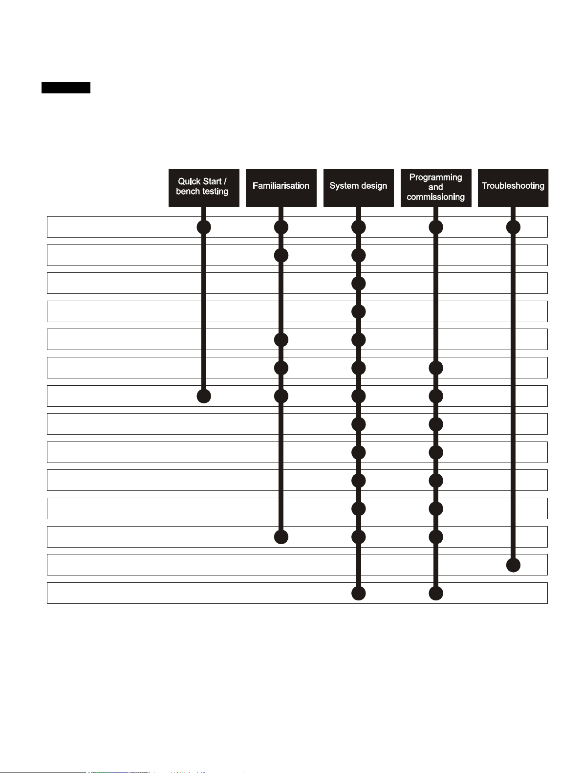
How to use this guide
NOTE
1 Safety information
2 Product information
3 Mechanical installation
4 Electrical installation
5 Getting started
6 Basic parameters
7 Running the motor
8 Optimization
9 SMARTCARD operation
11 Advanced parameters
12 Technical data
13 Diagnostics
14 UL listing information
10 Onboard PLC
This user guide provides complete information for installing and operating the drive from start to finish.
The information is in logical order, taking the reader from receiving the drive through to fine tuning the performance.
There are specific safety warnings throughout this guide, located in the relevant sections. In addition, Chapter 1 Safety
Information contains general safety information. It is essential that the warnings are observed and the information
considered when working with or designing a system using the drive.
This map of the user guide helps to find the right sections for the task you wish to complete, but for specific information,
refer to Contents on page 4:
Page 4

Contents
1 Safety Information .................................7
1.1 Warnings, Cautions and Notes .............................7
1.2 Electrical safety - general warning ........................7
1.3 System design and safety of personnel ................7
1.4 Environmental limits ..............................................7
1.5 Compliance with regulations .................................7
1.6 Motor .....................................................................7
1.7 Adjusting parameters ............................................7
2 Product information ..............................8
2.1 Model number .......................................................8
2.2 Ratings ..................................................................9
2.3 Operating modes .................................................12
2.4 Compatible encoders ..........................................12
2.5 Drive features ......................................................13
2.6 Nameplate description ........................................15
2.7 Options ................................................................15
2.8 Items supplied with the drive ...............................18
3 Mechanical Installation .......................19
3.1 Safety information ...............................................19
3.2 Planning the installation ......................................20
3.3 Terminal cover removal .......................................20
3.4 Installing fuses in a Free Standing drive .............24
3.5 Baying Free Standing drives ...............................24
3.6 Free standing drive dimensions ..........................32
3.7 External EMC filter ..............................................36
3.8 Electrical terminals ..............................................39
3.9 Solutions Module installation / removal ...............42
3.10 Routine maintenance ..........................................43
4 Electrical Installation ...........................44
4.1 Power connections ..............................................45
4.2 AC supply requirements ......................................50
4.3 Auxiliary power supply ........................................51
4.4 Control 24Vdc supply ..........................................53
4.5 Ratings ................................................................53
4.6 Output circuit and motor protection .....................56
4.7 Braking ................................................................58
4.8 Ground leakage ...................................................59
4.9 EMC (Electromagnetic compatibility) ..................59
4.10 Serial communications connections ....................63
4.11 Control connections ............................................63
4.12 Encoder connections ...........................................67
4.13 SAFE TORQUE OFF (SECURE DISABLE) ........69
5 Getting Started.................................... 72
5.1 Understanding the display .................................. 72
5.2 Keypad operation ............................................... 72
5.3 Menu structure ................................................... 73
5.4 Menu 0 ............................................................... 74
5.5 Advanced menus ............................................... 75
5.6 Changing the operating mode ............................ 76
5.7 Saving parameters ............................................. 76
5.8 Restoring parameter defaults ............................. 76
5.9 Parameter access level and security ................. 77
5.10 Displaying parameters with non-default
values only ......................................................... 78
5.11 Displaying destination parameters only ............. 78
5.12 Serial communications ....................................... 78
6 Basic parameters ................................ 80
6.1 Single line descriptions ...................................... 80
6.2 Full descriptions ................................................. 84
7 Running the motor .............................. 94
7.1 Quick start Connections ..................................... 94
7.2 Changing the operating mode ............................ 94
7.3 Quick Start commissioning/start-up ................... 98
7.4 Quick start commissioning/start-up (CTSoft) ... 102
7.5 Setting up a feedback device ........................... 102
8 Optimization ...................................... 106
8.1 Motor map parameters ..................................... 106
8.2 Maximum motor rated current .......................... 116
8.3 Current limits .................................................... 116
8.4 Motor thermal protection .................................. 116
8.5 Switching frequency ......................................... 117
8.6 High speed operation ....................................... 117
9 SMARTCARD operation ................... 119
9.1 Introduction ...................................................... 119
9.2 Transferring data .............................................. 120
9.3 Data block header information ......................... 122
9.4 SMARTCARD parameters ............................... 122
9.5 SMARTCARD trips ........................................... 123
10 Onboard PLC ..................................... 125
10.1 Onboard PLC and SYPTLite ............................ 125
10.2 Benefits ............................................................ 125
10.3 Limitations ........................................................ 125
10.4 Getting started .................................................. 126
10.5 Onboard PLC parameters ................................ 126
10.6 Onboard PLC trips ........................................... 127
10.7 Onboard PLC and the SMARTCARD .............. 127
4 Unidrive SP Free Standing User Guide
www.controltechniques.com Issue Number: 1
Page 5

11 Advanced parameters .......................128
11.1 Menu 1: Frequency / speed reference ..............136
11.2 Menu 2: Ramps .................................................140
11.3 Menu 3: Frequency slaving, speed
feedback and speed control ..............................143
11.4 Menu 4: Torque and current control ..................148
11.5 Menu 5: Motor control .......................................152
11.6 Menu 6: Sequencer and clock ..........................157
11.7 Menu 7: Analog I/O ...........................................159
11.8 Menu 8: Digital I/O ............................................162
11.9 Menu 9: Programmable logic, motorized pot,
binary sum and timers .......................................165
11.10 Menu 10: Status and trips .................................168
11.11 Menu 11: General drive set-up .........................169
11.12 Menu 12: Threshold detectors, variable
selectors and brake control function .................170
11.13 Menu 13: Position control .................................176
11.14 Menu 14: User PID controller ............................182
11.15 Menus 15, 16 and 17: Solutions Module
set-up ................................................................185
11.16 Menu 18: Application menu 1 ...........................221
11.17 Menu 19: Application menu 2 ...........................221
11.18 Menu 20: Application menu 3 ...........................221
11.19 Menu 21: Second motor parameters ................222
11.20 Menu 22: Additional Menu 0 set-up ..................223
11.21 Advanced features ............................................224
12 Technical Data ...................................233
12.1 Drive technical data ..........................................233
12.2 Optional external EMC filters ............................241
13 Diagnostics ........................................242
13.1 Trip indications ..................................................242
13.2 Alarm indications ...............................................258
13.3 Status indications ..............................................258
13.4 Displaying the trip history ..................................259
13.5 Behaviour of the drive when tripped .................259
14 UL Listing Information ......................260
14.1 Common UL information ...................................260
14.2 Power dependant UL information .....................260
14.3 AC supply specification .....................................260
14.4 Maximum continuous output current .................260
14.5 Safety label .......................................................260
14.6 UL listed accessories ........................................260
List of figures ....................................261
List of tables ......................................263
Index ...................................................265
Unidrive SP Free Standing User Guide 5
Issue Number: 1 www.controltechniques.com
Page 6
Declaration of Conformity (size 6 to 9 Free Standing drives)
Control Techniques Ltd
The Gro
Newtown
Powys
UK
SY16 3BE
SP6411 SP6412
SP6431 SP6432
SP6611 SP6612
SP6631 SP6632
SP7411 SP7412
SP7431 SP7432
SP7611 SP7612
SP7631 SP7632
SP8411 SP8412 SP8413 SP8414
SP8431 SP8432 SP8433 SP8434
SP8611 SP8612 SP8613 SP8614
SP8631 SP8632 SP8633 SP8634
SP9411 SP9413 SP9414 SP9415
SP9431 SP9433 SP9434 SP9435
SP9611 SP9613 SP9614 SP9615
SP9631 SP9633 SP9634 SP9635
The AC variable speed drive products listed above have been designed
and manufactured in accordance with the following European
harmonized standards:
These products comply with the Low Voltage Directive 2006/95/EC, the
Electromagnetic Compatibility (EMC) Directive 2004/108/EC and the CE
Marking Directive 93/68/EEC.
Executive Vice President, Technology
Newtown
Date: 8th August 2007
These electronic drive products are intended to be used with
appropriate motors, controllers, electrical protection components
and other equipment to form complete end products or systems.
Compliance with safety and EMC regulations depends upon
installing and configuring drives correctly, including using the
specified input filters. The drives must be installed only by
professional assemblers who are familiar with requirements for
safety and EMC. The assembler is responsible for ensuring that the
end product or system complies with all the relevant laws in the
country where it is to be used. Refer to the User Guide. An EMC
Data Sheet is also available giving detailed EMC information.
EN 61800-5-1*
EN 61800-3
EN 61000-6-2
*Clause 5.2.3.8 of EN 61800-5-1:2003 (breakdown of components test)
has been amended to eliminate the 30A ground (earth) fuse, in
accordance with the draft edition 2 of IEC 61800-5-1
Adjustable speed electrical power drive systems safety requirements - electrical, thermal and energy
Adjustable speed electrical power drive systems.
EMC product standard including specific test methods
Electromagnetic compatibility (EMC). Generic
standards. Immunity standard for industrial
environments
6 Unidrive SP Free Standing User Guide
www.controltechniques.com Issue Number: 1
Page 7

Safety
WARNING
CAUTION
NOTE
Information
Product
information
Mechanical
Installation
Electrical
Installation
Getting
Started
Basic
parameters
Running
the motor
Optimization
SMARTCARD
operation
Onboard
PLC
Advanced
parameters
Technical
Data
Diagnostics
UL Listing
Information
1 Safety Information
1.1 Warnings, Cautions and Notes
A Warning contains information which is essential for
avoiding a safety hazard.
A Caution contains information which is necessary for
avoiding a risk of damage to the product or other equipment.
A Note contains information which helps to ensure correct operation of
the product.
1.2 Electrical safety - general warning
The voltages used in the drive can cause severe electrical shock and/or
burns, and could be lethal. Extreme care is necessary at all times when
working with or adjacent to the drive.
Specific warnings are given at the relevant places in this User Guide.
1.3 System design and safety of
The drive is intended as a component for professional incorporation into
complete equipment or a system. If installed incorrectly, the drive may
present a safety hazard.
The drive uses high voltages and currents, carries a high level of stored
electrical energy, and is used to control equipment which can cause
injury.
Close attention is required to the electrical installation and the system
design to avoid hazards either in normal operation or in the event of
equipment malfunction. System design, installation, commissioning/
start-up and maintenance must be carried out by personnel who have
the necessary training and experience. They must read this safety
information and this User Guide carefully.
The STOP and SAFE TORQUE OFF (SECURE DISABLE) function
functions of the drive do not isolate dangerous voltages from the output
of the drive or from any external option unit. The supply must be
disconnected by an approved electrical isolation device before gaining
access to the electrical connections.
With the sole exception of the SAFE TORQUE OFF (SECURE
DISABLE) function, none of the drive functions must be used to
ensure safety of personnel, i.e. they must not be used for safetyrelated functions.
Careful consideration must be given to the functions of the drive which
might result in a hazard, either through their intended behaviour or
through incorrect operation due to a fault. In any application where a
malfunction of the drive or its control system could lead to or allow
damage, loss or injury, a risk analysis must be carried out, and where
necessary, further measures taken to reduce the risk - for example, an
over-speed protection device in case of failure of the speed control, or a
fail-safe mechanical brake in case of loss of motor braking.
The SAFE TORQUE OFF (SECURE DISABLE) function has been
approved
prevention of unexpected starting of the drive. It may be used in a
safety-related application. The system designer is responsible for
ensuring that the complete system is safe and designed correctly
according to the relevant safety standards.
personnel
1
as meeting the requirements of EN954-1 category 3 for the
1.4 Environmental limits
Instructions in this User Guide regarding transport, storage, installation
and use of the drive must be complied with, including the specified
environmental limits. Drives must not be subjected to excessive physical
force.
1.5 Compliance with regulations
The installer is responsible for complying with all relevant regulations,
such as national wiring regulations, accident prevention regulations and
electromagnetic compatibility (EMC) regulations. Particular attention
must be given to the cross-sectional areas of conductors, the selection
of fuses or other protection, and protective earth (ground) connections.
This User Guide contains instruction for achieving compliance with
specific EMC standards.
Within the European Union, all machinery in which this product is used
must comply with the following directives:
98/37/EC: Safety of machinery.
89/336/EEC: Electromagnetic Compatibility.
1.6 Motor
Ensure the motor is installed in accordance with the manufacturer’s
recommendations. Ensure the motor shaft is not exposed.
Standard squirrel cage induction motors are designed for single speed
operation. If it is intended to use the capability of the drive to run a motor
at speeds above its designed maximum, it is strongly recommended that
the manufacturer is consulted first.
Low speeds may cause the motor to overheat because the cooling fan
becomes less effective. The motor should be installed with a protection
thermistor. If necessary, an electric forced vent fan should be used.
The values of the motor parameters set in the drive affect the protection
of the motor. The default values in the drive should not be relied upon.
It is essential that the correct value is entered in parameter 0.46 motor
rated current. This affects the thermal protection of the motor.
1.7 Adjusting parameters
Some parameters have a profound effect on the operation of the drive.
They must not be altered without careful consideration of the impact on
the controlled system. Measures must be taken to prevent unwanted
changes due to error or tampering.
1
Independent approval by BGIA has been given.
Unidrive SP Free Standing User Guide 7
Issue Number: 1 www.controltechniques.com
Page 8
Safety
Unidrive product line
SP- solution platform
SP frame size
6- Size 6
Voltage rating
4- 380V to 480V
1- Dynamic brake control
3- No dynamic brake control
Current rating step
Disconnect
None supplied (default)
Input fuses none supplied
F1- Ferraz DIN80
(factory fitted)
Enclosure rating
SP 6 4
11
-E23
-F1 -D1
7- Size 7
6- 500V to 690V
D1- Switch disconnector
IP21 (default)
E 23- IP23
Unidrive product line
SP- solution platform
SP frame size
8- Size 8
Voltage rating
4- 380V to 480V
1- Dynamic brake control
3- No dynamic brake control
Current rating step
Plinth depth
-100mm plinth depth
Input fuses none supplied
F1- Ferraz DIN80
(factory fitted)
Enclosure rating
9- Size 9
6- 500V to 690V
-B1 -200mm plinth depth
IP21 (default)
E 23- IP23
SP 8 4 1 1
-E23
-F1 -B1-P12
Input pulse number
6 pulse default
12 -12 pulse
SPMD
Module 2
SPMD
Module 1
(Master)
Front
SPMD
Module 4
SPMD
Module 3
SPMD
Module 2
SPMD
Master
Module 1
Front
Cubicle
1
Cubicle
2
SP8XXX SP9XXX
Information
Product
information
Mechanical
Installation
Electrical
Installation
Getting
Started
Basic
parameters
Running
the motor
Optimization
SMARTCARD
operation
Onboard
PLC
Advanced
parameters
Technical
Data
Diagnostics
2 Product information
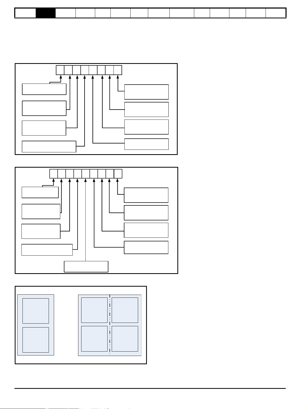
Unidrive SP Free Standing cubicles are made up to one or more SPM modules (SPMA / SPM), depending on size and current ratings.
2.1 Model number
The way in which the model numbers for the Unidrive SP range are formed is illustrated below.
Figure 2-1 Unidrive SP Free Standing size 6 and 7 order codes
UL Listing
Information
Figure 2-2 Unidrive SP Free Standing size 8 and 9 order codes
Figure 2-3 Drive configuration
8 Unidrive SP Free Standing User Guide
www.controltechniques.com Issue Number: 1
Page 9
Safety
Available output
current
Overload limit -
Heavy Duty
Maximum
continuous
current (above
50% base
speed) -
Normal Duty
Maximum
continuous
current -
Heavy Duty
Motor rated
current set
in the drive
Heavy Duty
- with high
overload capability
Normal Duty
Overload limit -
Normal Duty
NOTE
NOTE
Motor total
current (Pr 4.01)
as a percentage
of motor rated
current
Motor speed as a
percentage of base speed
100%
Max. permissible
continuous
current
100%
I t protection operates in this region
2
70%
50%15%
Pr = 0
Pr = 1
4.25
4.25
Motor total
current (Pr 4.01)
as a percentage
of motor rated
current
Motor speed as a
percentage of base speed
100%
Max. permissible
continuous
current
100%
I t protection operates in this region
2
70%
50%
Pr = 0
Pr = 1
4.25
4.25
Information
Product
information
Mechanical
Installation
Electrical
Installation
Getting
Started
Basic
parameters
Running
the motor
Optimization
SMARTCARD
operation
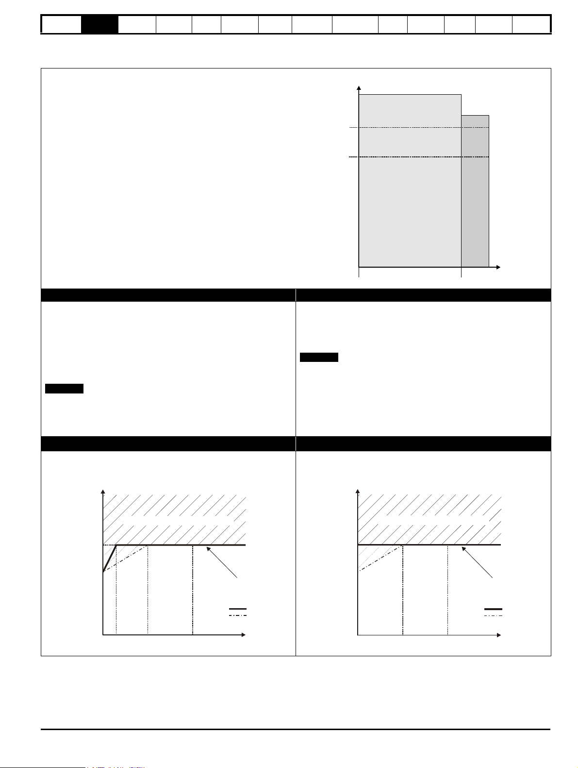
2.2 Ratings
The Unidrive SP is dual rated.
The setting of the motor rated current determines which rating applies Heavy Duty or Normal Duty.
The two ratings are compatible with motors designed to IEC60034.
The graph aside illustrates the difference between Normal Duty and
Heavy Duty with respect to continuous current rating and short term
overload limits.
Normal Duty Heavy Duty (default)
For applications which use Self ventilated (TENV/TEFC) induction
motors and require a low overload capability, and full torque at low
speeds is not required (e.g. fans, pumps).
Self ventilated (TENV/TEFC) induction motors require increased
protection against overload due to the reduced cooling effect of the fan
at low speed. To provide the correct level of protection the I
2
t software
operates at a level which is speed dependent. This is illustrated in the
graph below.
The speed at which the low speed protection takes effect can be
changed by the setting of Pr 4.25. The protection starts when the motor
speed is below 15% of base speed when Pr 4.25 = 0 (default) and below
50% when Pr 4.25 = 1.
Operation of motor I2t protection (It.AC trip)
Motor I2t protection is fixed as shown below and is compatible with:
• Self ventilated (TENV/TEFC) induction motors
For constant torque applications or applications which require a high
overload capability, or full torque is required at low speeds (e.g. winders,
hoists).
The thermal protection is set to protect force ventilated induction motors
and permanent magnet servo motors by default.
N
If the application uses a self ventilated (TENV/TEFC) induction motor
and increased thermal protection is required for speeds below 50% base
speed, then this can be enabled by setting Pr 4.25 = 1.
Motor I2t protection defaults to be compatible with:
• Forced ventilation induction motors
• Permanent magnet servo motors
Onboard
PLC
Advanced
parameters
Technical
Data
Diagnostics
UL Listing
Information
Unidrive SP Free Standing User Guide 9
Issue Number: 1 www.controltechniques.com
Page 10
Safety
565758
5
9
565758
5
9
Information
Product
information
Mechanical
Installation
Electrical
Installation
Getting
Started
Basic
parameters
Running
the motor
Optimization
SMARTCARD
operation
Onboard
PLC
Advanced
parameters
Technical
Data
Diagnostics
UL Listing
Information
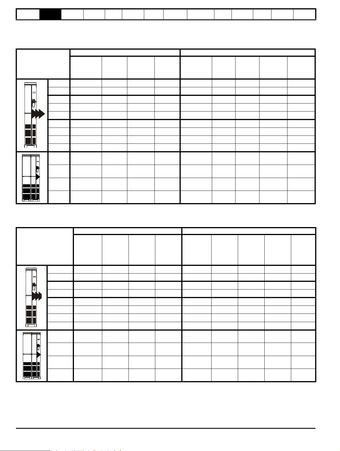
The continuous current ratings given are for maximum 40°C (104°F) for the standard drive and 33°C (91°F) for the IP23 variant, 1000m altitude and
3.0 kHz switching. Derating is required for higher switching frequencies, higher ambient temperatures and high altitude. For further information, refer
to section 12.1.1 Power and current ratings (Derating for switching frequency and temperature) on page 229.
Table 2-1 400V standard (IP21) Free Standing drive ratings at 40°C (104°F) 6 pulse or 12 pulse (380V to 480V ±10%)
Normal Duty Heavy Duty
Model
Maximum
continuous
output current
Peak
current
AAkWhpA
64X1 205 226 110 150 180 232 270 90 150
64X2 236 260 132 200 210 271 315 110 150
74X1 290 319 160 250 238 307 357 132 200
74X2 335 369 185 280 290 373 435 160 250
74X2* 350 385 200 300 290 374 435 160 250
84X1 389 428 225 300 335 432 503 185 280
84X2 450 495 250 400 389 502 584 225 300
84X3 545 600 315 450 450 581 675 250 400
84X4 620 682 355 500 545 703 818 315 450
94X1 690 759 400 600 620 800 930 355 500
94X3 900 990 500 800 790 1019 1185 450 700
Nominal
power
at 400V
Motor
power
at 460V
Maximum
continuous
output current
Open loop
peak
current
AA
Closed
loop peak
current
Nominal
power
at 400V
kW hp
Motor
power
at 460V
94X4 1010 1111 560 900 900 1125 1305 500 800
94X5 1164 1280 675 1000 1010 1303 1515 560 900
*When used in a maximum ambient temperature of 35ºC, the Normal Duty output current rating of the SP74X2 is 350A allowing the drive to run
200kW motors.
Table 2-2 690V standard (IP21) Free Standing drive ratings at 40°C (104°F) 6 pulse or 12 pulse (500V to 690V ±10%)
Normal duty Heavy duty
Model
Maximum
continuous
output
current
Peak
current
Nominal
power at
690V
Motor
power at
575V
Maximum
continuous
output
current
Open loop
peak
current
Closed
loop peak
current
Nominal
power at
690V
Motor
power at
575V
AAkWhpA AAkWhp
66X1 125 138 110 125 100 129 150 90 110
66X2 144 158 132 150 125 161 188 110 125
76X1 168 185 160 150 144 186 216 132 150
76X2 192 211 185 200 168 217 252 160 150
86X1 231 254 200 250 186 240 279 185 200
86X2 266 293 225 300 231 298 347 200 250
86X3 311 342 315 350 266 343 399 250 250
86X4 355 391 355 400 311 401 467 315 350
96X1 400 440 400 450 347 448 521 355 350
96X3 533 586 500 600 466 601 699 450 500
96X4 616 678 560 700 533 688 800 500 600
96X5 711 782 630 800 622 802 933 560 700
10 Unidrive SP Free Standing User Guide
www.controltechniques.com Issue Number: 1
Page 11
Safety
565758
5
9
565758
5
9
Information
Product
information
Mechanical
Installation
Electrical
Installation
Getting
Started
Basic
parameters
Running
the motor
Optimization
SMARTCARD
operation
Onboard
PLC
Advanced
parameters
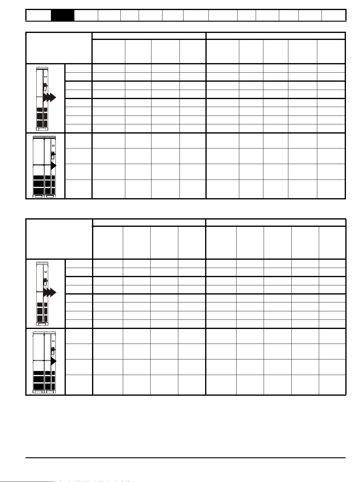
Table 2-3 400V IP23 Free Standing drive ratings at 33°C (91°F) 6 pulse or 12 pulse (380V to 480V ±10%)
Normal Duty Heavy Duty
Model
Maximum
continuous
output current
Peak
current
AAkWhpA
64X1-E23 205 226 110 150 180 232 270 90 150
64X2-E23 236 260 132 200 210 271 315 110 150
74X1-E23 290 319 160 250 238 307 357 132 200
74X2-E23 335 369 185 280 290 374 435 160 250
84X1-E23 389 428 225 300 335 432 503 185 280
84X2-E23 450 495 250 400 389 502 584 225 300
84X3-E23 545 600 315 450 450 581 675 250 400
84X4-E23 620 682 355 500 545 703 818 315 450
94X1-E23 690 759 400 600 620 800 930 355 500
94X3-E23 900 990 500 800 790 1019 1185 450 700
94X4-E23* 1010 1111 56 0 90 0 900 1125 1305 500 800
94X5-E23* 1164 1280 675 1000 1010 1303 1515 560 900
Nominal
power
at 400V
Motor
power
at 460V
Maximum
continuous
output current
Open
loop peak
current
AA
Technical
Closed
loop peak
current
Diagnostics
Data
Nominal
power
at 400V
kW hp
UL Listing
Information
Motor
power
at 460V
*Ratings for SP94X4 E23 and SP94X5 E23 are for an ambient temperature of 30°C
Table 2-4 690V IP23 Free Standing drive ratings at 33°C (104°F) 6 pulse or 12 pulse (575V to 690V ±10%)
Normal duty Heavy duty
Maximum
continuous
output
current
Open
loop peak
current
Model
Maximum
continuous
output
current
Peak
current
Nominal
power at
690V
Motor
power at
575V
AAkWhpAAAkWhp
66X1-E23 125 138 110 125 100 129 150 90 110
66X2-E23 144 158 132 150 125 161 188 110 125
76X1-E23 168 185 160 150 144 186 216 132 150
76X2-E23 192 211 185 200 168 217 252 160 150
86X1-E23 231 254 200 250 186 240 279 185 200
86X2-E23 266 293 225 300 231 298 347 200 250
86X3-E23 311 342 315 350 266 343 399 250 250
86X4-E23 355 391 355 400 311 401 467 315 350
96X1-E23 400 440 400 450 347 448 521 355 350
96X3-E23 533 586 500 600 466 601 699 450 500
96X4-E23* 616 678 560 700 533 688 800 500 600
Closed
loop peak
current
Nominal
power at
690V
Motor
power at
575V
96X5-E23* 711 782 630 800 622 802 933 560 700
* Ratings for SP96X4 E23 and SP96X5 E23 are for an ambient temperature of 30°C
Unidrive SP Free Standing User Guide 11
Issue Number: 1 www.controltechniques.com
Page 12

Safety
NOTE
Information
Product
information
Mechanical
Installation
Electrical
Installation
Getting
Started
Basic
parameters
Running
the motor
Optimization
SMARTCARD
operation
Onboard
PLC
Advanced
parameters
Technical
Data
Diagnostics
UL Listing
Information
2.2.1 Typical short term overload limits
The maximum percentage overload limit changes depending on the selected motor. Variations in motor rated current, motor power factor and motor
leakage inductance all result in changes in the maximum possible overload. The exact value for a specific motor can be calculated using the
equations detailed in Menu 4 in the Advanced User Guide.
Typical values are shown in the table below for closed loop vector (VT) and open loop (OL) modes:
Table 2-5 Typical overload limits for size 6 to 9
Operating mode Closed loop from cold Closed loop from 100% Open loop from cold Open loop from 100%
Normal Duty overload with motor rated current = drive rated current 110% for 165s 110% for 9s 110% for 165s 110% for 9s
Heavy Duty overload with motor rated current = drive rated current 150% for 60s 150% for 8s 129% for 97s 129% for 15s
Generally the drive rated current is higher than the matching motor rated current allowing a higher level of overload than the default setting.
The time allowed in the overload region is proportionally reduced at very low output frequency on some drive ratings.
The maximum overload level which can be attained is independent of the speed.
2.3 Operating modes
The Unidrive SP is designed to operate in any of the following modes:
1. Open loop mode
Open loop vector mode
Fixed V/F mode (V/Hz)
Quadratic V/F mode (V/Hz)
2. RFC mode
3. Closed loop vector
Servo
4. Regen
2.3.1 Open loop mode
The drive applies power to the motor at frequencies varied by the user.
The motor speed is a result of the output frequency of the drive and slip
due to the mechanical load. The drive can improve the speed control of
the motor by applying slip compensation. The performance at low speed
depends on whether V/F mode or open loop vector mode is selected.
For further details refer to section 8.1.1 Open loop motor control on
page 106.
Open loop vector mode
The voltage applied to the motor is directly proportional to the frequency
except at low speed where the drive uses motor parameters to apply the
correct voltage to keep the flux constant under varying load conditions.
Typically 100% torque is available down to 1Hz for a 50Hz motor.
Fixed V/F mode
The voltage applied to the motor is directly proportional to the frequency
except at low speed where a voltage boost is provided which is set by
the user. This mode can be used for multi-motor applications.
Typically 100% torque is available down to 4Hz for a 50Hz motor.
Quadratic V/F mode
The voltage applied to the motor is directly proportional to the square of
the frequency except at low speed where a voltage boost is provided
which is set by the user. This mode can be used for running fan or pump
applications with quadratic load characteristics or for multi-motor
applications. This mode is not suitable for applications requiring a high
starting torque.
2.3.2 RFC mode
Rotor flux control provides closed loop control without the need for
position feedback by using current, voltages and key motor parameters
to estimate the motor speed. It can eliminate instability traditionally
associated with open loop control such as operating large motors with
light loads at low frequencies.
For further details, refer to section 8.1.2 RFC mode on page 108.
2.3.3 Closed loop vector mode
For use with induction motors with a feedback device installed.
The drive directly controls the speed of the motor using the feedback
device to ensure the rotor speed is exactly as demanded. Motor flux is
accurately controlled at all times to provide full torque all the way down
to zero speed.
2.3.4 Servo
For use with permanent magnet brushless motors with a feedback
device installed.
The drive directly controls the speed of the motor using the feedback
device to ensure the rotor speed is exactly as demanded. Flux control is
not required because the motor is self excited by the permanent
magnets which form part of the rotor.
Absolute position information is required from the feedback device to
ensure the output voltage is accurately matched to the back EMF of the
motor. Full torque is available all the way down to zero speed.
2.3.5 Regen
Free Standing drives are not intended to be used in regen mode.
2.4 Compatible encoders
Table 2-6 Encoders compatible with Unidrive SP
Encoder type
Quadrature incremental encoders with or without
marker pulse
Quadrature incremental encoders with UVW
commutation signals for absolute position for
permanent magnet motors with or without marker pulse
Forward / reverse incremental encoders with or
without marker pulse
Forward / reverse incremental encoders with UVW
commutation signals for absolute position for
permanent magnet motors with or without marker pulse
Frequency and direction incremental encoders with
or without marker pulse
Frequency and direction incremental encoders with
UVW commutation signals for absolute position for
permanent magnet motors with or without marker pulse
Sincos incremental encoders SC (6)
Heidenhain sincos encoders with Endat comms for
absolute position
Stegmann sincos encoders with Hiperface comms
for absolute position
Sincos encoders with SSI comms for absolute
position
SSI encoders (Gray code or binary) SSI (10)
Endat comms only encoders EndAt (8)
UVW commutation only encoders* Ab.SErvo (3)
* This feedback device provides very low resolution feedback and should
not be used for applications requiring a high level of performance
Pr 3.38
setting
Ab (0)
Ab.SErvo (3)
Fr (2)
Fr.SErvo (5)
Fd (1)
Fd.SErvo (4)
SC.EndAt (9)
SC.HiPEr (7)
SC.SSI (11)
12 Unidrive SP Free Standing User Guide
www.controltechniques.com Issue Number: 1
Page 13
Safety
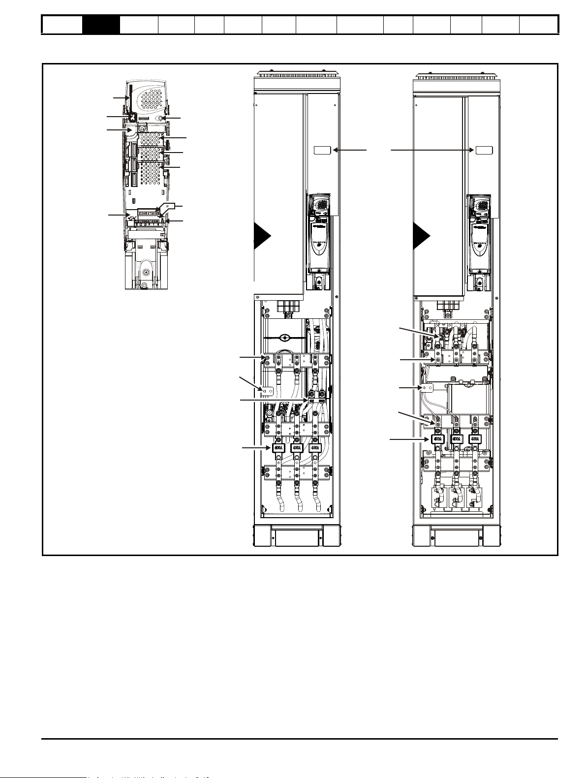
Ground
connections
Ground
connections
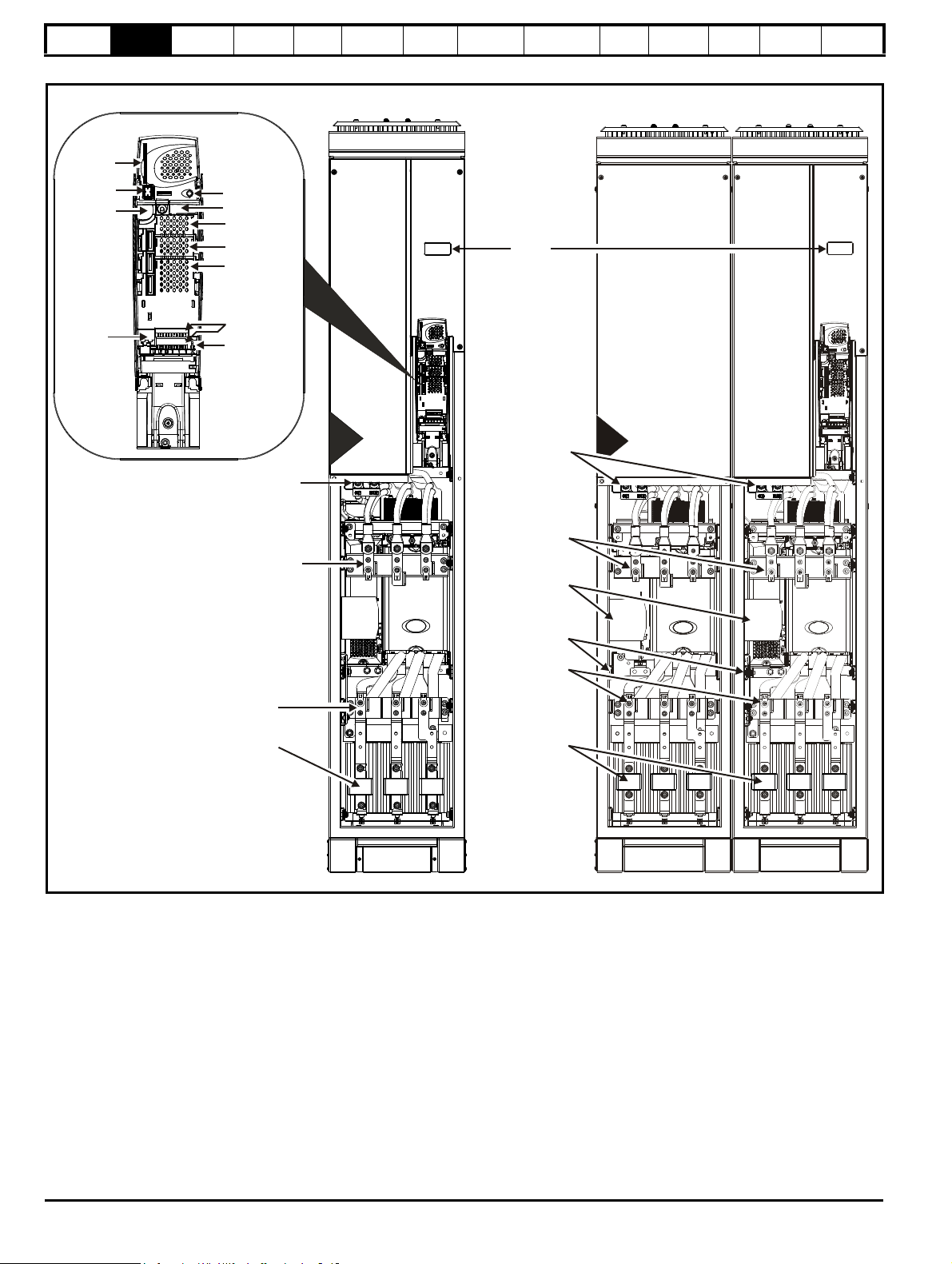
6
7
Motor
connections
Braking terminals
(optional)
Internal fuse
location
Braking terminals
(optional)
Motor
connections
Internal fuse
location
AC supply
connections
Rating
label
Solutions Module
slot 2
SMARTCARD
slot
Keypad
connection
Serial port
connector
Encoder
connection
Control terminals
Solutions Module
slot 1
Solutions Module
slot 3
Status LED
Relay terminals
Information
Product
information
Mechanical
Installation
Electrical
Installation
Getting
Started
Basic
parameters
2.5 Drive features
Figure 2-4 Features of the size 6 and 7 Free Standing drive
Running
the motor
Optimization
SMARTCARD
operation
Onboard
PLC
Advanced
parameters
Technical
Data
Diagnostics
UL Listing
Information
Unidrive SP Free Standing User Guide 13
Issue Number: 1 www.controltechniques.com
Page 14
Safety
9
Motor
connections
AC supply
connections
24V power
supply
Ground
connections
Internal fuse
location
SMARTCARD
slot
Keypad
connection
Encoder
connection
8
Ratings
label
Brake
connections
(optional)
Motor
connections
Brake
connections
(optional)
Status LED
Rating label
Solutions
Module slot1
Serial port
connector
Relay terminals
Control terminals
Solutions
Module slot 2
Solutions
Module slot 3
8
AC supply
connections
Internal fuse
location
Information
Product
information
Mechanical
Installation
Electrical
Installation
Getting
Started
Basic
parameters
Figure 2-5 Features of the size 8 and 9 Free Standing drive
Running
the motor
Optimization
SMARTCARD
operation
Onboard
PLC
Advanced
parameters
Technical
Data
Diagnostics
UL Listing
Information
14 Unidrive SP Free Standing User Guide
www.controltechniques.com Issue Number: 1
Page 15

Safety
Model
Heavy Duty /
Normal Duty
power rating
Customer and
date code
Approvals
Please read manual before connecting.
SP8414 315/355kW
STDN39
Electric Shock Risk: Wait 10 mins between
disconnecting supply & removing covers
Serial No: 3000005001
Made in U.K
Serial
number
SP 150 TH
I/P 380-480V 50-60Hz 3ph 678A
O/P 0-480V
540/620A
Input voltage
Output voltage
Input
frequency
No. of phases &
Typical input current for
Normal Duty rating
Heavy Duty /
Normal Duty
rating output current
www.controltechniques.com
U
L
R
CUS
LISTED8D14
IND.
CONT.
EQ.
E171230
CE approval Europe
C Tick approval Australia
UL / cUL approval
USA &
Canada
R
Key to approvals
CT Comms
cable
Feedback Automation Fieldbus
Keypad
SMARTCARD*
Information
Product
information
Mechanical
Installation
Electrical
Installation
Getting
Started
Basic
parameters
Running
the motor
2.6 Nameplate description
See Figure 2-1 and Figure 2-2 for location of the drive rating labels.
Figure 2-6 Typical drive rating label
2.7 Options
Figure 2-7 Options available with Unidrive SP
Optimization
SMARTCARD
operation
Onboard
PLC
Advanced
parameters
Technical
Data
Diagnostics
UL Listing
Information
* A SMARTCARD is provided as standard. For further information, refer
to Chapter 9 SMARTCARD operation on page 119.
Unidrive SP Free Standing User Guide 15
Issue Number: 1 www.controltechniques.com
Page 16

Safety
Inputs Outputs
• Incremental encoders • Quadrature
• SinCos encoders • Frequency and direction
• SSI encoders • SSI simulated outputs
• EnDat encoders
• Digital inputs x 3
• Analog output (voltage) x 1
• Digital I/O x 3 • Relay x 2
• Analog inputs (voltage) x 2
Information
Product
information
Mechanical
Installation
Electrical
Installation
Getting
Started
Basic
parameters
Running
the motor
Optimization
SMARTCARD
operation
Onboard
PLC
Advanced
parameters
Technical
Data
Diagnostics
UL Listing
Information
All Solutions Modules are color-coded in order to make identification easy. The following table shows the color-code key and gives further details on
their function.
Table 2-7 Solutions Module identification
Type Solutions Module Color Name Further Details
Universal Feedback interface
Feedback interface for the following devices:
Light Green
SM-Universal
Encoder Plus
Resolver interface
Light Blue SM-Resolver
Feedback interface for resolvers.
Simulated quadrature encoder outputs
Incremental encoder interface
Feedback
Brown SM-Encoder Plus
Feedback interface for incremental encoders without
commutation signals.
No simulated encoder outputs available
Incremental encoder interface
Feedback interface for incremental encoders without
commutation signals.
Simulated encoder output for quadrature, frequency and
Dark Brown
SM-Encoder Output
Plus
direction signals
Drive encoder input converter
Provides screw terminal interface for encoder wiring and spade
terminal for shield
Single ended encoder interface
Provides an interface for single ended ABZ or UVW encoder
signals, such as those from hall effect sensors. 15V and 24V
versions are available.
N/A
N/A
15-way D-type
converter
Single ended
encoder interface
(15V or 24V)
Extended I/O interface
Increases the I/O capability by adding the following to the
Yellow SM-I/O Plus
existing I/O in the drive:
Automation
(I/O
Expansion)
Yellow SM-I/O 32
Dark Yellow SM-I/O Lite
Dark Red SM-I/O Timer
Turquoise SM-I/O PELV
Olive SM-I/O 120V
Cobalt Blue
SM-I/O 24V
Protected
Extended I/O interface
Increase the I/O capability by adding the following to the
existing I/O in the drive:
• High speed digital I/O x 32
• +24V output
Additional I/O
1 x Analog input (± 10V bi-polar or current modes)
1 x Analog output (0-10V or current modes)
3 x Digital input and 1 x Relay
Additional I/O with real time clock
As per SM-I/O Lite but with the addition of a Real Time Clock
for scheduling drive running
Isolated I/O to NAMUR NE37 specifications
For chemical industry applications
1 x Analog input (current modes)
2 x Analog outputs (current modes)
4 x Digital input / outputs, 1 x Digital input, 2 x Relay outputs
Additional I/O conforming to IEC 61131-2 120Vac
6 digital inputs and 2 relay outputs rated for 120Vac operation
Additional I/O with overvoltage protection up to 48V
2 x Analog outputs (current modes)
4 x Digital input / outputs, 3 x Digital inputs, 2 x Relay outputs
16 Unidrive SP Free Standing User Guide
www.controltechniques.com Issue Number: 1
Page 17

Safety
Information
Product
information
Mechanical
Installation
Electrical
Installation
Getting
Started
Basic
parameters
Running
the motor
Optimization
SMARTCARD
operation
Onboard
PLC
Advanced
parameters
Table 2-7 Solutions Module identification
Type Solutions Module Color Name Further Details
Applications Processor (with CTNet)
Dark Green SM-Applications
nd
2
processor for running pre-defined and /or customer created
application software with CTNet support
Applications Processor
White SM-Applications Lite
nd
2
processor for running pre-defined and /or customer created
application software
Motion Controller
Automation
(Applications)
Dark Blue SM-EZMotion
1
1
/2 axis motion controller with processor for running customer
created application specific software
Applications Processor (with CTNet)
Moss Green
SM-Applications
Plus
nd
2
processor for running pre-defined and /or customer created
application software with CTNet support. Enhanced
performance over SM-Applications
Applications Processor
White
SM-Applications Lite
V2
nd
2
processor for running pre-defined and /or customer created
application software. Enhanced performance over SMApplications Lite
Technical
Data
Diagnostics
UL Listing
Information
Fieldbus
Purple SM-PROFIBUS-DP
Medium Grey SM-DeviceNet
Dark Grey SM-INTERBUS
Pink SM-CAN
Light Grey SM-CANopen
Red SM-SERCOS
Beige SM-Ethernet
Profibus option
PROFIBUS DP adapter for communications with the drive
DeviceNet option
Devicenet adapter for communications with the drive
Interbus option
Interbus adapter for communications with the drive
CAN option
CAN adapter for communications with the drive
CANopen option
CANopen adapter for communications with the drive
SERCOS option
Class B compliant. Torque velocity and position control modes
supported with data rates (bit/s): 2MB, 4MB, 8MB and 16MB.
Minimum 250μs network cycle time. Two digital high speed
probe inputs 1μs for position capture
Ethernet option
10 base-T / 100 base-T; Supports web pages, SMTP mail and
multiple protocols: DHCP IP addressing; Standard RJ45
connection
Brown Red SM-EtherCAT
Pale Green SM-LON
EtherCAT option
EtherCAT adapter for communications with the drive
LonWorks option
LonWorks adapter for communications with the drive
SLM interface
The SM-SLM allows SLM feedback to be connected directly to
SLM Orange SM-SLM
the Unidrive SP drive and allows operation in either of the
following modes:
• Encoder only mode
• Host mode
Unidrive SP Free Standing User Guide 17
Issue Number: 1 www.controltechniques.com
Page 18

Safety
Information
Product
information
Mechanical
Installation
Electrical
Installation
Getting
Started
Basic
parameters
Running
the motor
Optimization
SMARTCARD
operation
Onboard
PLC
Table 2-8 Keypad identification
Type Keypad Name Further Details
Advanced
parameters
Technical
Data
Diagnostics
UL Listing
Information
SM-Keypad
LED keypad option
Keypad with a LED display for size 1 to 9
Keypad
SM-Keypad Plus
LCD keypad option
Keypad with an alpha-numeric LCD display with Help function
2.8 Items supplied with the drive
The drive is supplied with a printed manual, a SMARTCARD, a safety
information booklet, the Certificate of Quality, and a CD ROM containing
all related product documentation and software tools. All accessories
(e.g. control connectors) are supplied installed to the drive.
18 Unidrive SP Free Standing User Guide
www.controltechniques.com Issue Number: 1
Page 19
Safety
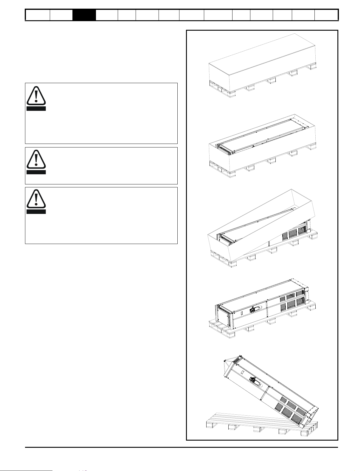
WARNING
WARNING
WARNING
Information
Product
information
Mechanical
Installation
Electrical
Installation
Getting
Started
Basic
parameters
Running
the motor
3 Mechanical Installation
This chapter describes how to use all mechanical details to install the
drive. Key features of this chapter include:
• Baying of Free Standing drives
• Terminal location and torque settings
• Solutions Module installation
3.1 Safety information
Follow the instructions
The mechanical and electrical installation instructions must
be adhered to. Any questions or doubt should be referred to
the supplier of the equipment. It is the responsibility of the
owner or user to ensure that the installation of the drive and
any external option unit, and the way in which they are
operated and maintained, comply with the requirements of
the Health and Safety at Work Act in the United Kingdom or
applicable legislation and regulations and codes of practice in
the country in which the equipment is used.
Competence of the installer
The drive must be installed by professional assemblers who
are familiar with the requirements for safety and EMC. The
assembler is responsible for ensuring that the end product or
system complies with all the relevant laws in the country
where it is to be used.
The weights of the size 6 to 9 Free Standing drives are as
follows:
Size 6: 199 kg (438 lb)
Size 7: 214 kg (471 lb)
Size 8: 266 kg (586 lb)
Size 9: 532 kg (1173 lb)
Lift the drive by the method detailed in Figure 3-2 on page 20.
Do not tilt the drive. The centre of gravity of the unit is high.
An overturning unit can cause physical injury.
Optimization
SMARTCARD
operation
Onboard
PLC
Advanced
parameters
Technical
Data
Diagnostics
Figure 3-1 Removing a Free Standing drive from packaging
UL Listing
Information
Unidrive SP Free Standing User Guide 19
Issue Number: 1 www.controltechniques.com
Page 20
Safety
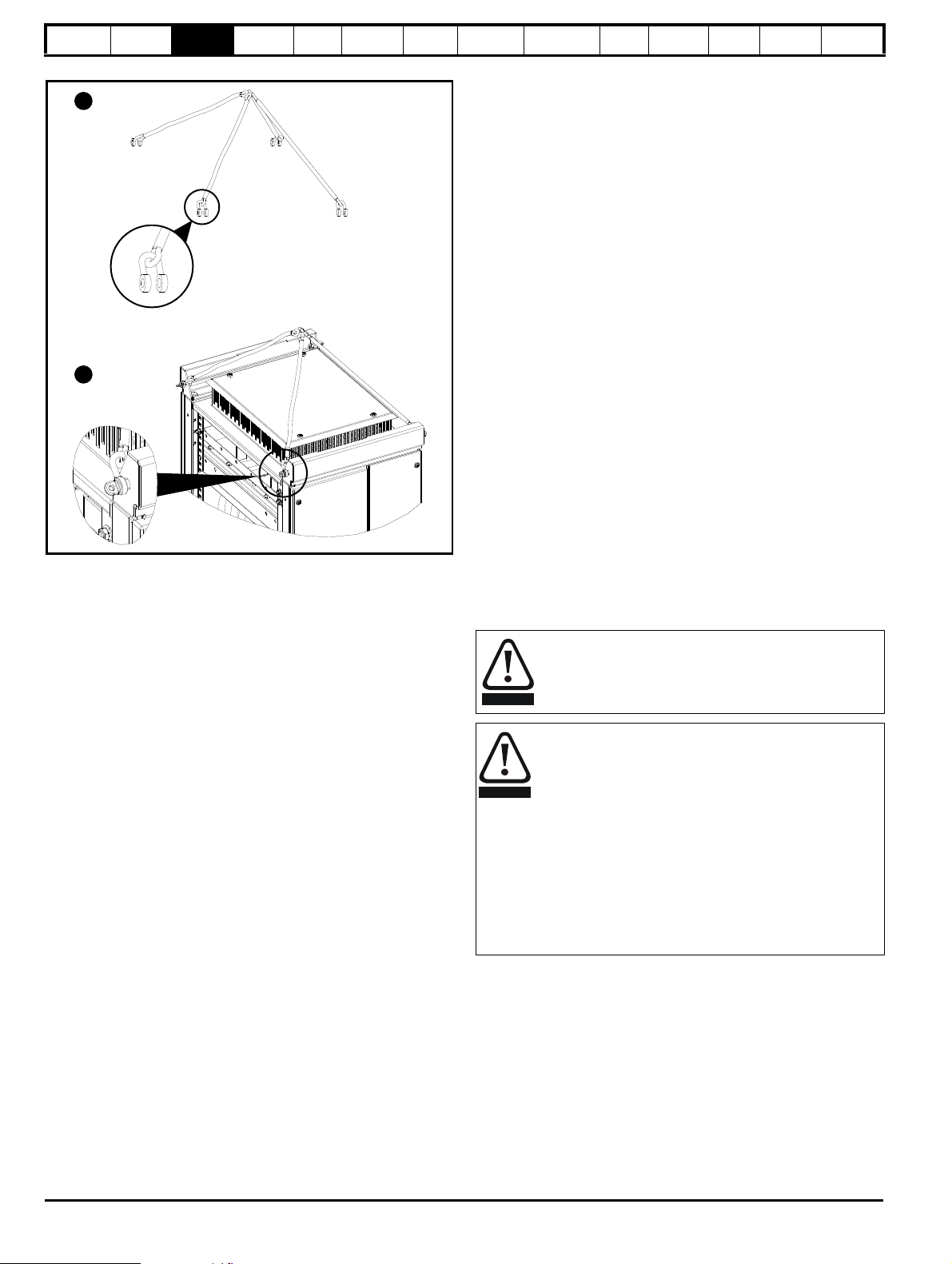
1
2
WARNING
WARNING
Information
Product
information
Mechanical
Installation
Electrical
Installation
Getting
Started
Basic
parameters
Figure 3-2 Lifting the Free Standing drive
1. Attach “D” shackles to each rope
2. Attach each shackle to the lifting plate. Ensure angle of each rope is
>45°.
3.2 Planning the installation
The following considerations must be made when planning the
installation:
3.2.1 Access
Access must be restricted to authorized personnel only. Safety
regulations which apply at the place of use must be complied with.
The standard Free Standing drive is rated for IP21. An IP23 version is
also available.
3.2.2 Environmental protection
The drive must be protected from:
• moisture, including dripping water or spraying water and
condensation.
• contamination with electrically conductive material
• contamination with any form of dust which may restrict the fan, or
impair airflow over various components
• temperature beyond the specified operating and storage ranges
• corrosive gasses
3.2.3 Cooling
The inlet and outlet vents on the drive must not be restricted or covered.
The ambient temperature must not exceed the specified operating
temperature of the drive. Some size 8 and size 9 models are installed
with a fan in the roof of the enclosure.
Care must be taken when installing Unidrive SP Free Standing drives
side by side, to prevent recirculation of heated air. Where a Free
Standing drive with no roof fan is installed next to a drive with a roof fan it
is recommended that some additional baffling be added between the
roof canopies to prevent recirculation of heated air in the drive with no
roof fan. If no baffling is added between drives fitted with roof fans and
those without a distance of 0.5 metres must be maintained between
drives.
Certain Unidrive SP size 6 and 7 Free Standing drives are fitted with
smaller roof fans, baffling should also be fitted if installed side by side
Running
the motor
Optimization
SMARTCARD
operation
Onboard
PLC
Advanced
parameters
Technical
Data
Diagnostics
UL Listing
Information
with a Unidrive size 8 or 9 Free Standing drive (with larger roof fan) or a
distance of 0.5 metres (19.69in) must also be maintained between
drives.
A distance of 300mm (11.81in) should be maintained between the top of
the Free Standing drive roof canopy and the ceiling of the room in which
the Free Standing drive is installed.
Refer to Table 12-8 Roof mounted fans on page 236 for details of which
Free Standing models have roof fans fitted.
3.2.4 Electrical safety
The installation must be safe under normal and fault conditions.
Electrical installation instructions are given in Chapter 4 Electrical
Installation on page 44.
3.2.5 Electromagnetic compatibility
Variable speed drives are powerful electronic circuits which can cause
electromagnetic interference if not installed correctly with careful
attention to the layout of the wiring.
Some simple routine precautions can prevent disturbance to typical
industrial control equipment.
If it is necessary to meet strict emission limits, or if it is known that
electromagnetically sensitive equipment is located nearby, then full
precautions must be observed. In-built into the drive, is an internal EMC
filter, which reduces emissions under certain conditions. If these
conditions are exceeded, then the use of an external EMC filter may be
required at the drive inputs, which must be located as close to the drive
as possible. A suitable location, such as a SP-Incomer Shell, must be
made available for the housing filters and allowance made for carefully
segregated wiring. Both levels of precautions are covered in section
4.9 EMC (Electromagnetic compatibility) on page 59.
3.2.6 Hazardous areas
The drive must not be located in a classified hazardous area .
3.3 Terminal cover removal
Isolation device
The AC supply must be disconnected from the drive using an
approved isolation device before any cover is removed from
the drive or before any servicing work is performed.
Stored charge
The drive contains capacitors that remain charged to a
potentially lethal voltage after the AC supply has been
disconnected. If the drive has been energized, the AC
supply must be isolated at least ten minutes before work
may continue.
Normally, the capacitors are discharged by an internal
resistor. Under certain, unusual fault conditions, it is possible
that the capacitors may fail to discharge, or be prevented
from being discharged by a voltage applied to the output
terminals. If the drive has failed in a manner that causes the
display to go blank immediately, it is possible the capacitors
will not be discharged. In this case, consult Control
Techniques or their authorized distributor.
20 Unidrive SP Free Standing User Guide
www.controltechniques.com Issue Number: 1
Page 21
Safety
5
8
Control
Control
Input / output
Input / output
6
8
9
Input / output
878
8
Information
Figure 3-3 Location and identification of terminal covers for Free Standing drives
Product
information
Mechanical
Installation
Electrical
Installation
Getting
Started
Basic
parameters
Running
the motor
Optimization
SMARTCARD
operation
Onboard
PLC
Advanced
parameters
Technical
Data
Diagnostics
UL Listing
Information
Unidrive SP Free Standing User Guide 21
Issue Number: 1 www.controltechniques.com
Page 22
Safety
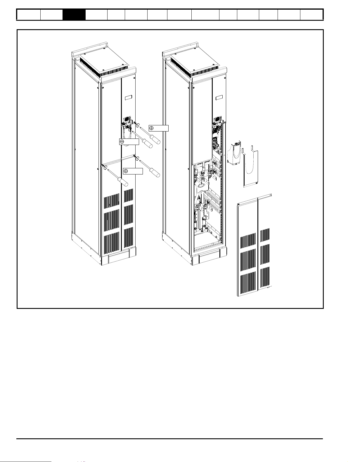
Pozi Pz4
Pozi Pz4
Pozi Pz2
Information
Product
information
Mechanical
Installation
Electrical
Installation
Getting
Started
Basic
parameters
Running
the motor
Optimization
SMARTCARD
operation
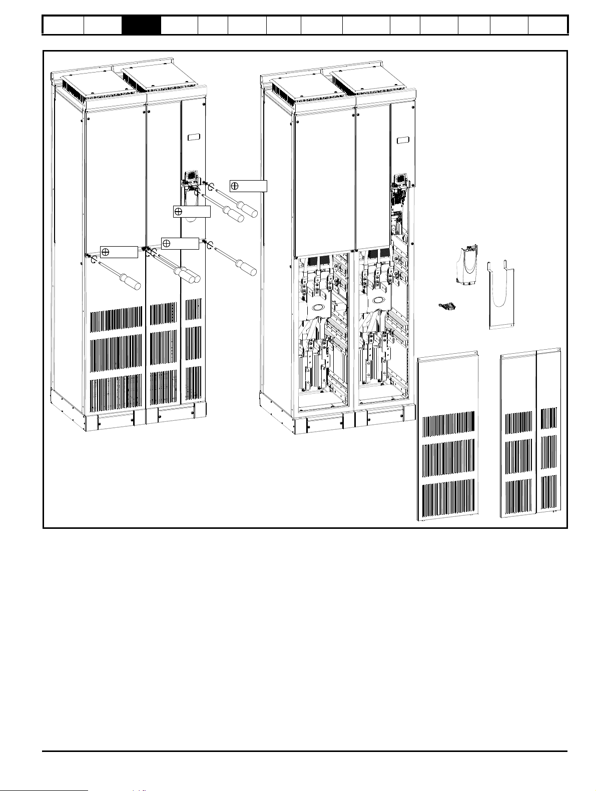
Figure 3-4 Removing the size 6, 7 and 8 terminal covers from the Free Standing drive
Onboard
PLC
Advanced
parameters
Technical
Data
Diagnostics
UL Listing
Information
22 Unidrive SP Free Standing User Guide
www.controltechniques.com Issue Number: 1
Page 23
Safety
Pozi Pz4
Pozi Pz4
Pozi Pz4
Pozi Pz2
Information
Product
information
Mechanical
Installation
Electrical
Installation
Getting
Started
Basic
parameters
Running
the motor
Optimization
Figure 3-5 Removing the size 9 terminal covers from the Free Standing drive
SMARTCARD
operation
Onboard
PLC
Advanced
parameters
Technical
Data
Diagnostics
UL Listing
Information
Unidrive SP Free Standing User Guide 23
Issue Number: 1 www.controltechniques.com
Page 24
Safety
CAUTION
1 2
Lower mounting hole
for DIN80 type fuse
Lower mounting hole
for DIN110 type fuse
Upper mounting
stud
1
2
3
111
2
2
2
3
3
3
Loosely secure fuse to
lower mounting hole
with M10x25
(Hex Head bolt)
Secure fuse to upper
mounting stud with
M10 nut
Tighten three M10
nut and three M10
hexhead bolts to
12 Nm (8.8 lb ft)
1
2
3
1 1
1
2 2 2
Loosely secure fuse to
lower mounting hole
with M10x25
(Hex Head bolt)
Secure fuse to upper
mounting stud with
M10 nut
Tighten three M10
nut and three M10
hexhead bolts to
12 Nm (8.8 lb ft)
1
2
3
1 1
1
2 2 2
Information
Product
information
Mechanical
Installation
Electrical
Installation
Getting
Started
Basic
parameters
Running
the motor
Optimization
SMARTCARD
operation
Onboard
PLC
Advanced
parameters
Technical
Data
Diagnostics
UL Listing
Information
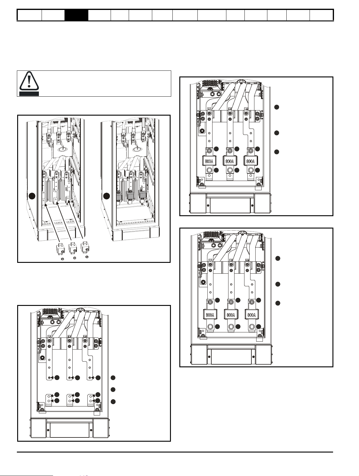
3.4 Installing fuses in a Free Standing drive
Fuses must be installed. Free Standing drives can be ordered with or without mains supply fuses. Factory fitted fuses are indicated by a -F1 suffix
after the order code. See section 2.1 Model number on page 8 for more information on order codes. Alternatively mains supply fuses (type DIN80
only) can be purchased separately from Control Techniques. See Table 4-5 on page 55 for further information.
Instructions for installing fuses on 6 pulse drives are shown in shown in section 3.4.1. See section section 3.5.3 Electrical connections for baying a
size 9 master to slave for information on installing fuses on 12 pulse drives.
Figure 3-8 Installing DIN80 type fuses
Ensure fuses are aligned with the busbar.
3.4.1 Sizes 6&7 or sizes 8&9 (with date code S17)
Figure 3-6 Size 6&7or sizes 8&9 with date code S17 or earlier
I
The six M10 nuts holding the fuses must be tightened to a torque of 12N
m (8.8lb.ft)
3.4.2 Size 8 & 9 (with date code S18 or later)
Unidrive SP size 8 and 9 Free Standing with date code of S18 or later
can accept type DIN80 or type DIN110 fuses.
Figure 3-7 Identification of fuse mounting holes
Figure 3-9 Installing DIN110 type fuses
3.5 Baying Free Standing drives
This section describes how to connect or 'bay' the master and slave
drives of a size 9 together, or an incomer to a size 8 or 9 Free Standing
drive.
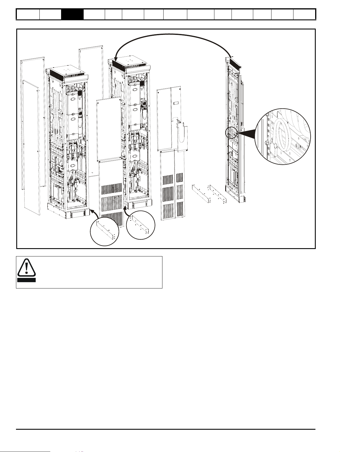
3.5.1 Preparation for baying
The following diagrams show how to prepare the incomer/applications
shell and the size 8 / 9 Free Standing drives for baying.
1. Remove all front, rear and side panels as shown. All screws for
these are Pozi Pz4
2. Disconnect the ground cable connections from the front, rear and
side panels by removing the M6 nuts and star washers.
24 Unidrive SP Free Standing User Guide
www.controltechniques.com Issue Number: 1
Page 25

Safety
Information
Product
information
Mechanical
Installation
Electrical
Installation
Getting
Started
Basic
parameters
Running
the motor
Figure 3-10 Preparation for baying the incomer/applications shell
Optimization
SMARTCARD
operation
Onboard
PLC
Advanced
parameters
Technical
Data
Diagnostics
UL Listing
Information
An incomer shell is supplied with no side panels.
Figure 3-11 Preparation for baying the size 8 Free Standing drive
Unidrive SP Free Standing User Guide 25
Issue Number: 1 www.controltechniques.com
Page 26
Safety
Remove panels as shown
Location of paralleling cable
on size 9 master
WARNING
Information
Product
information
Mechanical
Installation
Electrical
Installation
Getting
Started
Basic
parameters
Running
the motor
Optimization
SMARTCARD
operation
Figure 3-12 Preparation for baying the size 9 Free Standing drive (slave and master)
Onboard
PLC
Advanced
parameters
Technical
Data
Diagnostics
UL Listing
Information
The total weight of the size 9 Free Standing drive is: 532 kg
(1173 lb), i.e. 266 kg (586 lb) per enclosure.
Lift the drive by the method detailed in Figure 3-2 on page 20.
Do not tilt the drive. The centre of gravity of the unit is high.
An overturning unit can cause physical injury.
26 Unidrive SP Free Standing User Guide
www.controltechniques.com Issue Number: 1
Page 27
Safety
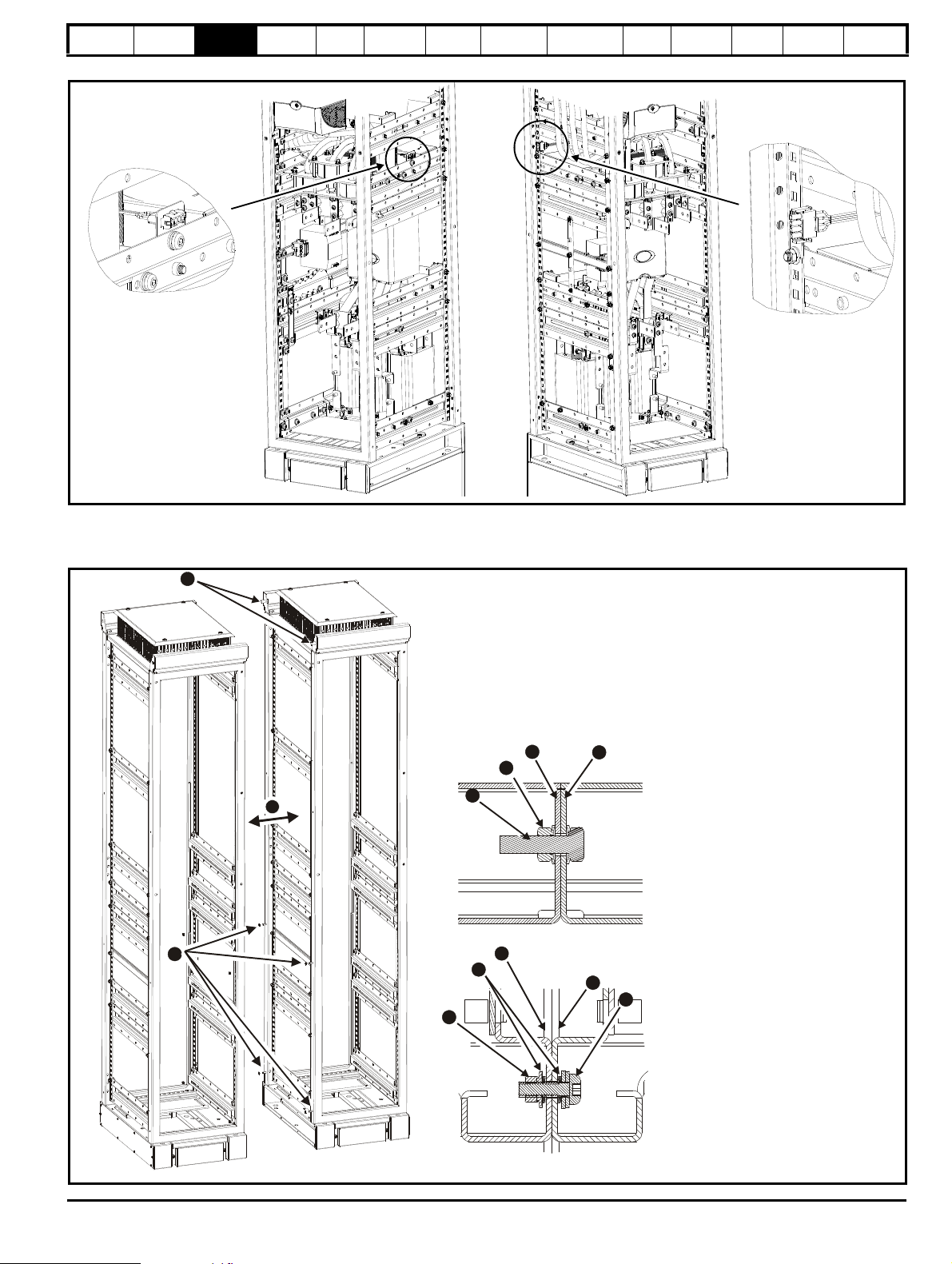
Location of rectifier status
connector on slave cubicle
Location of rectifier status
connector on master
Connect status connections
together prior to joining
cubicles
1
2
3
1
2
3
4
5
1
2
3
4
Position the Free Standing drive and incomer together
Fix in two places (front and back) with M10 nuts and bolts,
through the lifting plates
Fix in four places (two at the front and two at the back) with
M6 nuts, bolts and washers
1.
2.
3.
Lifting plates M10 fastening (2 places)
1. M10 flange headed set screw
2. M10 nut
3. Incomer frame
4. Free Standing drive frame
Frames M6 fastening (4 places)
1. M6 nut
2. M6 star lock washer
3. In
4.
5. M6 screw
comer frame
Free Standing drive frame
Once the Free Standing drive and incomer are in position they must be bolted to the floor
Information
Product
information
Mechanical
Installation
Electrical
Installation
Getting
Started
Basic
parameters
Running
the motor
Optimization
SMARTCARD
operation
Figure 3-13 Location of the rectifier status connectors for size 9 Free Standing drive
Onboard
PLC
Advanced
parameters
Technical
Data
Diagnostics
UL Listing
Information
3.5.2 Baying of Free Standing drives / incomers
The following generic drawing demonstrates how to bay any type of Free Standing drive or incomer together.
Figure 3-14 Baying of Free Standing drive and incomer
Unidrive SP Free Standing User Guide 27
Issue Number: 1 www.controltechniques.com
Page 28

Safety
1
Information
Product
information
Mechanical
Installation
Electrical
Installation
Getting
Started
Basic
parameters
Running
the motor
Optimization
3.5.3 Electrical connections for baying a size 9 master to slave
Figure 3-15 Installing the parallel cable from a size 9 master to slave
SMARTCARD
operation
Onboard
PLC
Advanced
parameters
Technical
Data
Diagnostics
UL Listing
Information
1. Remove size 9 slave interface cover
2. Connect the paralleling cable to the size 9 slave input slot
3. Replace size 9 slave interface cover
4. Replace all size 9 Free Standing drive panels
28 Unidrive SP Free Standing User Guide
www.controltechniques.com Issue Number: 1
Page 29
Safety
1
2
3
4 5
6
Information
Product
information
Mechanical
Installation
Electrical
Installation
Getting
Started
Basic
parameters
Running
the motor
Optimization
SMARTCARD
operation
Onboard
PLC
6 pulse size 9 input busbar connections
Figure 3-16 Input busbar connections between the 6 pulse size 9 master and slave (and incomer)
Advanced
parameters
Technical
Data
Diagnostics
UL Listing
Information
1. Master and slave cubicles bayed together
From the size 9 baying kit:
2. Fit the safety ground link with (M10 nuts) (torque 20Nm [14.75 lb ft])
3. Fit the incomer EMC plate with (M8 x 20 screws) (torque 12Nm [8.85 lb ft])
4. & 5. Fit the input parallel busbar with (M8 x 20 screws) (torque 17Nm [12.5 lb ft]); and M6 x 30 insulating spacer with (M6 x 12 screws) (torque
12Nm [8.85 lb ft])
6. Fit the input parallel busbar with (M8 x 20 screws) (torque 17Nm [12.5 lb ft])
Unidrive SP Free Standing User Guide 29
Issue Number: 1 www.controltechniques.com
Page 30

Safety
1
3
54
7
2
8
6
NOTE
Information
Product
information
Mechanical
Installation
Electrical
Installation
Getting
Started
Basic
parameters
Running
the motor
Optimization
SMARTCARD
operation
Onboard
PLC
12 pulse size 9 input busbar connections
Figure 3-17 Input busbar connections between the 12 pulse size 9 master and slave (and incomer)
Advanced
parameters
Technical
Data
Diagnostics
UL Listing
Information
1. Fit the safety ground busbar (top) with supplied M10 nuts and EMC gland joining plate (bottom) with existing M8x20 torx screws
2. a) Fit the following to the size 8 or 9 slave cubicle: Safety ground busbar (top) with 2 x M10 nuts and EMC baying plate (bottom) with supplied 2 x
M8x20 torx screws and 2 x M8 nuts
b) Mechanically bay the 12 pulse incomer cubicle
c) Complete safety and EMC ground connections: Fit supplied 2 x M10 nuts and M10 x 25 bolts to connect safety ground busbar. Also fit 2 x
M8x20 torx screws and M8 nuts to connect EMC baying plate to 12 pulse incomer cubicle.
3. Fit: 2 x 12 pulse busbar fuse links with supplied M6x16 torx screws
4. Fit: 2 x 12 pulse busbars, 4 x 30mm insulator, 6 x M6x16 screws, 4 x M8x20 screws, L1(A) terminal marker
Pre-fit insulators to busbars before fitting to cubicle.
30 Unidrive SP Free Standing User Guide
www.controltechniques.com Issue Number: 1
Page 31

Safety
NOTE
1
2
3
1
2
3
4
Information
Product
information
Mechanical
Installation
Electrical
Installation
Getting
Started
Basic
parameters
Running
the motor
Optimization
SMARTCARD
operation
Onboard
PLC
Advanced
parameters
Technical
Data
Diagnostics
UL Listing
Information
5. Fit 400A fuses with 4 x M10 nuts supplied
Factory fitted fuses are available as a selectable option, alternatively fuses can be ordered and supplied separately. It is recommended to fit the fuses
integral with this baying procedure. The fuses can be easily independently removed should the need arise when in service.
6. Fit: 2 x 12 pulse busbars, 2 x 12 pulse busbar fuse links, 4 x 30mm insulators, 8 x M6x16 torx screws, 4 x M8x20 torx screws, 4 x M10 nuts to fit
400A fuses, L2(A) terminal marker
7. Fit: 2 x 12 pulse busbars, 2 x 12 pulse busbar fuse links, 4 x M6x16 torx screws, 4 x M8x20 torx screws, 4 x M10 nuts to fit 400A fuses, L3(A) terminal
marker
8. Repeat procedure for fitting L1(B), L2(B) and L3(B) input busbars
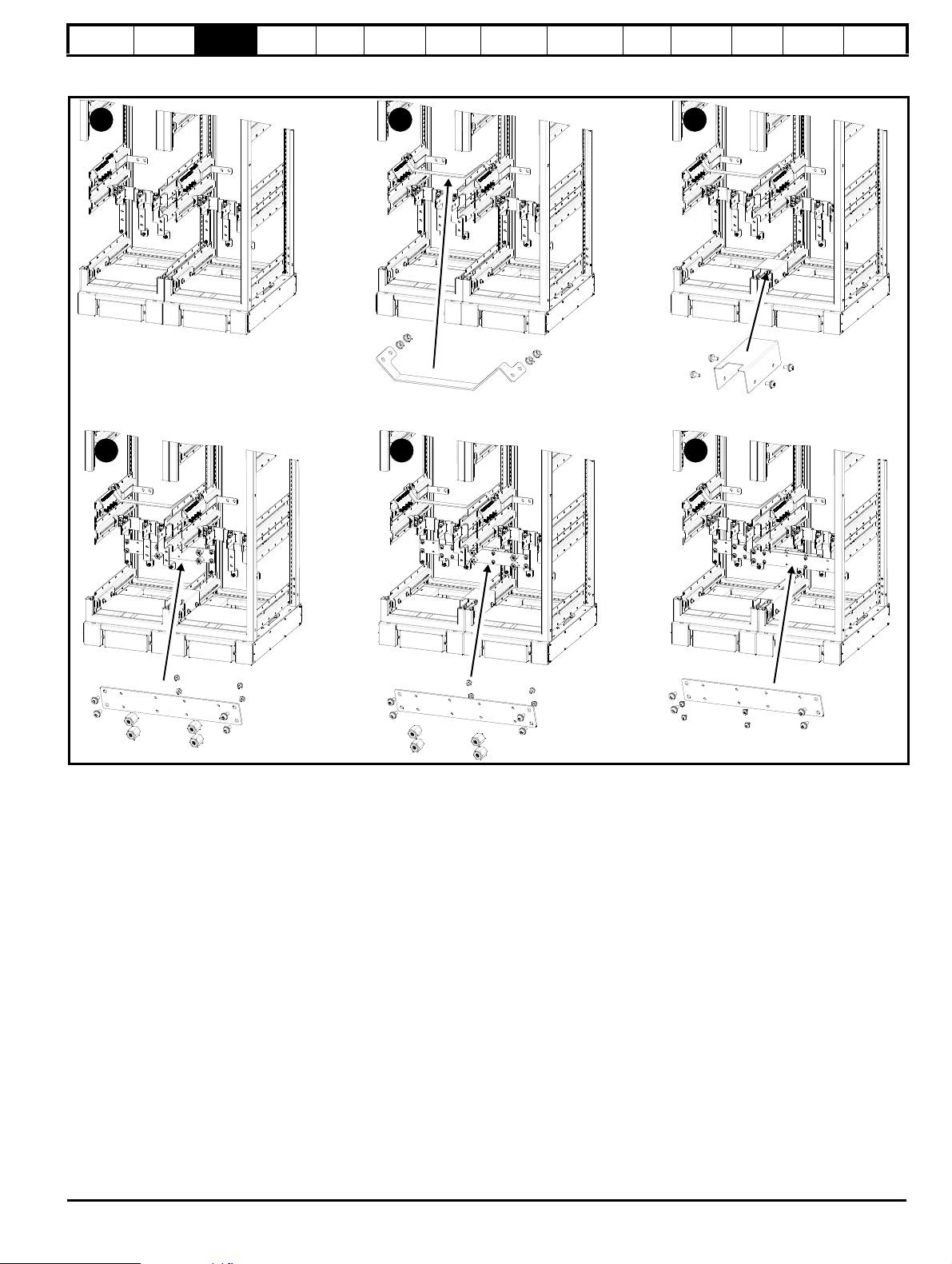
3.5.4 Electrical connections for baying an incomer to size 8 and 9
The following diagrams look at specific features of baying a 6 pulse incomer to a 6 pulse drive, and baying the master and slave cabinets of a 6 pulse
size 9 together. All images show the appropriate components exploded and installed.
Figure 3-18 Baying a 6 pulse incomer to a 6 pulse Free Standing drive (size 8 shown)
1. Install paralleling busbars from incomer to the Free Standing drive input terminals and mount with M8 screws (17 N m, [12.5 lb.ft])
2. Install EMC bracket when EMC filter required
3. Install ground clamp
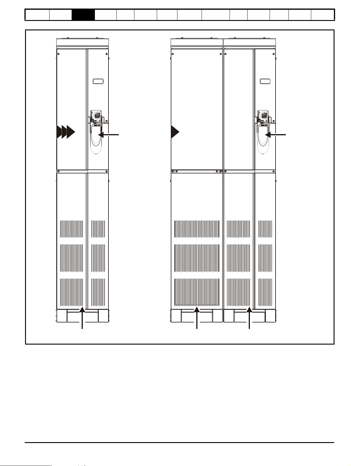
3.5.5 Gland plate removal
The images below shows how to remove the gland plate from a Free Standing drive.
Figure 3-19 Removing the cable gland plate from the Free Standing drive for "glanding off" the cable
Unidrive SP Free Standing User Guide 31
Issue Number: 1 www.controltechniques.com
Page 32

Safety
600mm
(23.622in)
520mm
(20.472in)
315mm (12.402in)
404.6mm (15.929in)
∅
20mm (0.787in)
400mm
(15.748in)
600mm
(23.622in)
2209.0mm
(86.7in)
Information
Product
information
Mechanical
Installation
Electrical
Installation
Getting
Started
Basic
parameters
3.6 Free standing drive dimensions
Figure 3-20 Incomer/applications shell dimensions
Running
the motor
Optimization
SMARTCARD
operation
Onboard
PLC
Advanced
parameters
Technical
Data
Diagnostics
UL Listing
Information
32 Unidrive SP Free Standing User Guide
www.controltechniques.com Issue Number: 1
Page 33

Safety
630mm
(24.80in)
400mm
(15.75in)
404.6mm
(15.93in)
315mm
(12.40in)
∅
20mm (0.79in)
520mm
(20.47in)
600mm
(23.62in)
2330mm
(91.73in)
Information
Product
information
Mechanical
Installation
Electrical
Installation
Getting
Started
Basic
parameters
the motor
Figure 3-21 Size 6 and 7 drives with integral line side options
Running
Optimization
SMARTCARD
operation
Onboard
PLC
Advanced
parameters
Technical
Data
Diagnostics
UL Listing
Information
Unidrive SP Free Standing User Guide 33
Issue Number: 1 www.controltechniques.com
Page 34

Safety
400mm
(15.748in)
600mm
(23.622in)
2209mm
(86.7in)
6
600mm
(23.622in)
520mm
(20.472in)
315mm (12.402in)
404.6mm (15.929in)
∅
20mm (0.787in)
7 8
Dimensions shown above are for IP21 drives
Note:-
Dimensions for IP23 drives are:-
H - 2248.5 mm (88.521 in)
D - 653 mm (25.70 in)
W =- 404.6 mm (15.929 in)
Information
Product
information
Mechanical
Installation
Electrical
Installation
Getting
Started
Basic
parameters
Figure 3-22 Size 6, 7 and 8 Free Standing drive dimensions
Running
the motor
Optimization
SMARTCARD
operation
Onboard
PLC
Advanced
parameters
Technical
Data
Diagnostics
UL Listing
Information
34 Unidrive SP Free Standing User Guide
www.controltechniques.com Issue Number: 1
Page 35

Safety
800mm
(31.496in)
600mm
(23.622in)
2205mm
(86.811in)
9
600mm
(23.622in)
520mm
(20.472in)
∅
20mm (0.787in)
89.60mm
(3.528in)
719.60mm (28.331in)
809.20mm (31.858in)
Dimensions shown above are for IP21 drives
Note:-
Dimensions for IP23 drives are:-
H - 2248.5 mm (88.521 in)
D - 653 mm (25.70 in)
W - 809.2 mm (31.85 in)
Information
Product
information
Mechanical
Installation
Electrical
Installation
Getting
Started
parameters
Figure 3-23 Size 9 Free Standing drive dimensions
Basic
Running
the motor
Optimization
SMARTCARD
operation
Onboard
PLC
Advanced
parameters
Technical
Data
Diagnostics
UL Listing
Information
Unidrive SP Free Standing User Guide 35
Issue Number: 1 www.controltechniques.com
Page 36

Safety
NOTE
Information
Product
information
Mechanical
Installation
Electrical
Installation
Getting
Started
Basic
parameters
Running
the motor
Optimization
SMARTCARD
operation
Onboard
PLC
Advanced
parameters
Technical
Data
Diagnostics
UL Listing
Information
3.7 External EMC filter
In order to provide our customers with a degree of flexibility, external EMC filters have been sourced from two manufacturers: Schaffner & Epcos.
Filter details for each drive rating are provided in the tables below. Both the Schaffner and Epcos filters meet the same specifications
Table 3-1 Size 6 and 7 Free Standing drive EMC filter details
Drive
CT part no Weight
Epcos
SP64X1 4200-6815 15 kg (33.0 lb)
SP64X2 4200-6816 21 kg (46.3 lb)
SP66X1 4200-6804 21 kg (46.3 lb)
SP66X2 4200-6804 21 kg (46.3 lb)
SP74X1 4200-6817 21 kg (46.3 lb)
SP74X2 4200-6817 21 kg (46.3 lb)
SP76X1 4200-6804 21 kg (46.3 lb)
SP76X2 4200-6804 21 kg (46.3 lb)
Table 3-2 Size 8 and 9 Free Standing drive EMC filter details for 6 pulse drives
Drive
CT part no. Weight CT part no. Weight
Schaffner Epcos
SP84X1 4200-6808 11 kg (25.3 lb) 4200-6801 22 kg (48.5 lb)
SP84X2 4200-6808 11 kg (25.3 lb) 4200-6801 22 kg (48.5 lb)
SP84X3 4200-6808 11 kg (25.3 lb) 4200-6801 22 kg (48.5 lb)
SP84X4 4200-6809 18 kg (39.7 lb) 4200-6802 28 kg (61.7 lb)
SP86X1 4200-6811 10.5 kg (23.1 lb) 4200-6804 21 kg (46.3 lb)
SP86X2 4200-6811 10.5 kg (23.1 lb) 4200-6804 21 kg (46.3 lb)
SP86X3 4200-6812 10.5 kg (23.1 lb) 4200-6805 21 kg (46.3 lb)
SP86X4 4200-6812 10.5 kg (23.1 lb) 4200-6805 21 kg (46.3 lb)
SP94X1 4200-6809 18 kg (39.7 lb) 4200-6802 28 kg (61.7 lb)
SP94X3 4200-6809 18 kg (39.7 lb) 4200-6802 28 kg (61.7 lb)
SP94X4 4200-6810 27 kg (59.5 lb) 4200-6803 34 kg (75.0 lb)
SP94X5 4200-6810 27 kg (59.5 lb) 4200-6803 34 kg (75.0 lb)
SP96X1 4200-6812 10.5 kg (23.1 lb) 4200-6805 21 kg (46.3 lb)
SP96X3 4200-6813 11 kg (25.3 lb) 4200-6806 22 kg (48.5 lb)
SP96X4 4200-6814 18 kg (39.7 lb) 4200-6807 28 kg (61.7 lb)
SP96X5 4200-6814 18 kg (39.7 lb) 4200-6807 28 kg (61.7 lb)
Contact the supplier of the drive for information on EMC filters for 12 pulse drives.
36 Unidrive SP Free Standing User Guide
www.controltechniques.com Issue Number: 1
Page 37

Safety
A
B
D
EFHGGCZ
W
Z
V
V
CYV
B
G
V
Y: 12 mm
∅
Information
Product
information
Mechanical
Installation
Electrical
Installation
Getting
Started
Basic
parameters
Figure 3-24 Size 6 , 7, 8 and 9 EPCOS external EMC filter
Running
the motor
Optimization
SMARTCARD
operation
Onboard
PLC
Advanced
parameters
Technical
Data
Diagnostics
UL Listing
Information
Table 3-3 Size 6, 7, 8 and 9 EPCOS External EMC filter dimensions
CT part no. A B C D E F G H W V Z
4200 - 6804
4200 - 6815 40 mm 190 mm 190 mm
4200 - 6816
300 mm 120±0.5 mm
4200 - 6817 235 mm
4200 - 6801
4200 - 6802
350 mm 145±0.5 mm
4200 - 6803 400 mm 170±0.5 mm 92±3 mm 590±2 mm
4200 - 6805 300 mm 120±0.5 mm
4200 - 6806
4200 - 6807 80 mm 275 mm 3 mm 52±3 mm 454±3 mm Ø14
350 mm 145±0.5 mm
60 mm 260 mm 260 mm
260 mm
2 mm
60 mm 260 mm
3 mm 440±2 mm
80 mm 300 mm 2.5 mm
60 mm
260 mm
275 mm
235 mm 2 mm 42±3 mm
42±2 mm 116 mm
52±3 mm
166 mm
116 mm
390±2 mm
460±2 mm
M10 Ø11
Ø14
M12
384±3 mm Ø11
434±3 mm
M10
Ø11
Unidrive SP Free Standing User Guide 37
Issue Number: 1 www.controltechniques.com
Page 38

Safety
A
B
D
EFH
G
G
C
Z
W
Z
V
V
CYV
V
B
G
Y: 12 mm
∅
Information
Product
information
Mechanical
Installation
Electrical
Installation
Getting
Started
Basic
parameters
Figure 3-25 Size 8 and 9 Schaffner external EMC filter
Running
the motor
Optimization
SMARTCARD
operation
Onboard
PLC
Advanced
parameters
Technical
Data
Diagnostics
UL Listing
Information
Table 3-4 Schaffner External EMC filter dimensions
CT part no. A B C D E F G H W V Z
4200-6808
4200-6811
300±1 mm 120±1 mm
4200-6813
4200-6809
350±1 mm 145±1 mm 280±1 mm 255 mm
4200-6810 400±1 mm 170±1 mm 300±1 mm 275 mm 90 mm 160 mm 580 mm
142 mm
260±1 mm 235 mm 2 mm 40 mm
60 mm
3 mm
50 mm 177 mm 450 mm
122 mm4200-6812
380 mm
Ø10.5
M12
Ø144200-6814
38 Unidrive SP Free Standing User Guide
www.controltechniques.com Issue Number: 1
Page 39

Safety
6
7
M10 nut
17mm AF
Output
terminals
Input terminals
M10 nut
and bolt
Ground
terminals
Internal fuse
location
M10 nut
17mm AF
M10 nut
17mm AF
M10 nut
17mm AF
Output
terminals
M10 nut
and bolt
Ground
terminals
Internal fuse
location
M10 nut
17mm AF
Input terminals
M10 nut
17mm AF
Control terminals
2.5mm
Relay terminals
3mm
Information
Product
information
Mechanical
Installation
Electrical
Installation
Getting
Started
Basic
parameters
Running
the motor
Optimization
SMARTCARD
operation
3.8 Electrical terminals
3.8.1 Location of the power and ground terminals
Figure 3-26 Location of power and ground terminals on Free Standing drives sizes 6 & 7
Onboard
PLC
Advanced
parameters
Technical
Data
Diagnostics
UL Listing
Information
Unidrive SP Free Standing User Guide 39
Issue Number: 1 www.controltechniques.com
Page 40

Safety
9
Control terminals
2.5mm
Relay terminals
3mm
M10 nut
17mm AF
M10 nut
17mm AF
10.5mm
Output
terminals
Output
terminals
Input busbar
Internal fuse
location
M10 nut
17mm AF
Internal fuse
location
M10 nut
17mm AF
M10
Ground stud
10.5mm
Input busbar
M10
Ground stud
8
Information
Product
information
Mechanical
Installation
Electrical
Installation
Getting
Started
Basic
parameters
Running
the motor
Optimization
SMARTCARD
operation
Onboard
PLC
Figure 3-27 Locations of the power and ground terminals on Free Standing drives sizes 8 and 9
Advanced
parameters
Technical
Data
Diagnostics
UL Listing
Information
40 Unidrive SP Free Standing User Guide
www.controltechniques.com Issue Number: 1
Page 41

Safety
WAR NING
Information
Product
information
Mechanical
Installation
Electrical
Installation
Getting
Started
parameters
3.8.2 Terminal sizes and torque settings
To avoid a fire hazard and maintain validity of the UL listing,
adhere to the specified tightening torques for the power and
ground terminals. Refer to the following tables.
Table 3-5 Drive control and relay terminal data
Model Connection type Torque setting
All Plug-in terminal block 0.5 N m (0.4 lb ft)
Tab l e 3-6 Te r mina l dat a
Model
AC terminals
size
6 2 x M10 2 x M10
7 2 x M10 2 x M10
2 x M10 clearance holes per
8
phase for parallel cables.
9
Torque tolerance ±10%
Table 3-7 EPCOS external EMC filter terminal data
DC and
braking
terminals
Internal fuse
12 N m
(8.8 lb ft)
Basic
Running
the motor
Ground
terminal
Optimization
SMARTCARD
operation
Onboard
PLC
Advanced
parameters
Technical
Data
Diagnostics
UL Listing
Information
CT Part
Number
Power
Connections
Max Torque
Ground Connections
Ground
Stud Size
Max torque
4200 - 6804 30 N m M10 10 N m (7.4 lb ft)
4200 - 6815 30 N m M10 10 N m (7.4 lb ft)
4200 - 6816 30 N m M10 10 N m (7.4 lb ft)
4200 - 6817 30 N m M10 10 N m (7.4 lb ft)
4200 - 6801 30 N m M10 10 N m (7.4 lb ft)
4200 - 6802 60 N m M12 15.5 N m (11.4 lb ft)
4200 - 6803 60 N m M12 15.5 N m (11.4 lb ft)
4200 - 6805 30 N m M10 10 N m (7.4 lb ft)
4200 - 6806 30 N m M10 10 N m (7.4 lb ft)
4200 - 6807 60 N m M12 15.5 N m (11.4 lb ft)
Table 3-8 Schaffner external EMC Filter terminal data
CT part number
Power
connections
Ground connections
Max torque Ground stud size Max torque
4200-6808 48 N m M12
4200-6811 48 N m M12
4200-6812 48 N m M12
4200-6813 48 N m M12
4200-6809 83 N m M12
4200-6814 83 N m M12
4200-6810 83 N m M12
Unidrive SP Free Standing User Guide 41
Issue Number: 1 www.controltechniques.com
Page 42

Safety
CAUTION
B
A
A
Solutions Module
in slot 1
Solutions Module
in slot 2
Solutions Module
in slot 3
NOTE
BAA
NOTE
Information
Product
information
Mechanical
Installation
Electrical
Installation
Getting
Started
Basic
parameters
Running
the motor
3.9 Solutions Module installation / removal
Power down the drive before installing / removing the Solutions Module. Failure to do so may result in damage to the product.
Figure 3-28 Installation and removal of a Solutions Module
Optimization
SMARTCARD
operation
Onboard
PLC
Advanced
parameters
Technical
Data
Diagnostics
UL Listing
Information
To install the Solutions Module, press down in the direction shown above until it clicks into place.
To remove the Solutions Module, press inwards at the points shown (A) and pull in the direction shown (B).
The drive has the facility for all three Solutions Module slots to be used at the same time, as illustrated.
N
It is recommended that the Solutions Module slots are used in the following order: slot 3, slot 2 and slot 1.
Figure 3-29 Installation and removal of a keypad
To install, align the keypad and press gently in the direction shown until it clicks into position.
To remove, while pressing the tabs inwards (A), gently lift the keypad in the direction indicated (B).
N
The keypad can be installed / removed while the drive is powered up and running a motor, providing that the drive is not operating in keypad mode.
42 Unidrive SP Free Standing User Guide
www.controltechniques.com Issue Number: 1
Page 43

Safety
Information
Product
information
Mechanical
Installation
Electrical
Installation
Getting
Started
Basic
parameters
Running
the motor
Optimization
SMARTCARD
operation
Onboard
PLC
Advanced
parameters
Technical
Data
Diagnostics
3.10 Routine maintenance
The drive should be installed in a cool, clean, well ventilated location. Contact of moisture and dust with the drive should be prevented.
Regular checks of the following should be carried out to ensure drive / installation reliability are maximized:
Environment
Ambient temperature Ensure the enclosure temperature remains at or below maximum specified
Dust
Moisture Ensure the drive enclosure shows no signs of condensation
Electrical
Screw connections Ensure all screw terminals remain tight
Crimp terminals
Cables Check all cables for signs of damage
Ensure the drive remains dust free – check that the heatsink and drive fan are not gathering dust.
The lifetime of the fan is reduced in dusty environments.
Ensure all crimp terminals remains tight – check for any discoloration which could indicate
overheating
UL Listing
Information
Unidrive SP Free Standing User Guide 43
Issue Number: 1 www.controltechniques.com
Page 44

Safety
WARNING
WARNING
WARNING
WARNING
WARNING
WARNING
WARNING
WARNING
Information
Product
information
Mechanical
Installation
Electrical
Installation
Getting
Started
Basic
parameters
Running
the motor
Optimization
SMARTCARD
operation
Onboard
PLC
Advanced
parameters
Technical
Data
Diagnostics
UL Listing
Information
4 Electrical Installation
Many cable management features have been incorporated into the
product, this chapter shows how to optimize them. Key features include:
• SAFE TORQUE OFF (SECURE DISABLE) function
• EMC compliance with shielding / grounding accessories
• Product rating, fusing and cabling information
• Brake resistor details (selection / ratings)
Electric shock risk
The voltages present in the following locations can cause
severe electric shock and may be lethal:
• AC supply cables and connections
• DC and brake cables, and connections
• Output cables and connections
• Many internal parts of the drive, and external option units
Unless otherwise indicated, control terminals are single
insulated and must not be touched.
Isolation device
The AC supply must be disconnected from the drive using
an approved isolation device before any cover is removed
from the drive or before any servicing work is performed.
STOP function
The STOP function does not remove dangerous voltages
from the drive, the motor or any external option units.
Fuses
The AC supply to the drive must be installed with suitable
protection against overload and short circuits. Table 4-3 on
page 54 shows the recommended fuse ratings. Failure to
observe this requirement will increase the risk of fire.
SAFE TORQUE OFF (SECURE DISABLE) function
The SAFE TORQUE OFF (SECURE DISABLE) function
does not remove dangerous voltages from the drive, the
motor or any external option units.
Stored charge
The drive contains capacitors that remain charged to a
potentially lethal voltage after the AC supply has been
disconnected. If the drive has been energized, the AC
supply must be isolated at least ten minutes before work
may continue.
Normally, the capacitors are discharged by an internal
resistor. Under certain, unusual fault conditions, it is possible
that the capacitors may fail to discharge, or be prevented
from being discharged by a voltage applied to the output
terminals. If the drive has failed in a manner that causes the
display to go blank immediately, it is possible the capacitors
will not be discharged. In this case, consult Control
Techniques or their authorized distributor.
Equipment supplied by plug and socket
Special attention must be given if the drive is installed in
equipment which is connected to the AC supply by a plug
and socket. The AC supply terminals of the drive are
connected to the internal capacitors through rectifier diodes
which are not intended to give safety isolation. If the plug
terminals can be touched when the plug is disconnected
from the socket, a means of automatically isolating the plug
from the drive must be used (e.g. a latching relay).
Permanent magnet motors
Permanent magnet motors generate electrical power if they
are rotated, even when the supply to the drive is
disconnected. If that happens then the drive will become
energized through its motor terminals.
If the motor load is capable of rotating the motor when the
supply is disconnected, then the motor must be isolated from
the drive before gaining access to any live parts.
44 Unidrive SP Free Standing User Guide
www.controltechniques.com Issue Number: 1
Page 45

Safety
Input connections
Mains
Supply
L1 L2
Optional EMC
filter
Fuses
L3
Supply
ground
L3L2L1
PE
Fuses*
W
VU
Motor
Optional ground
connection
Output connections
**
BR
Thermal
overload
protection
device
Optional (SPxx1x brake
versions only)
+DC
Information
Product
information
Mechanical
Installation
Electrical
Installation
Getting
Started
Basic
parameters
4.1 Power connections
4.1.1 AC and DC connections
Figure 4-1 Unidrive SP size 6 Free Standing drive power connections
Running
the motor
Optimization
SMARTCARD
operation
Onboard
PLC
Advanced
parameters
Technical
Data
Diagnostics
UL Listing
Information
* Free Standing drives are available fitted with or without fuses. If cubicles are supplied without fuses, the user must fit them during the installation.
Fuses may be purchased from Control Techniques, see Figure 4-3 on page 54, Figure 4-4 on page 54 and Figure 4-5 on page 55 for more
information.
** Cable shield must be bonded to gland plate.
Unidrive SP Free Standing User Guide 45
Issue Number: 1 www.controltechniques.com
Page 46

Safety
W
VU
Motor
Optional ground
connection
Output connections
Input connections
Mains
Supply
L1 L2
Optional EMC
filter
Fuses
L3
Supply
ground
L3L2L1
PE
Fuses*
**
BR
Thermal
overload
protection
device
Optional (SP7x1x brake
versions only)
+DC
Information
Product
information
Mechanical
Installation
Electrical
Installation
Getting
Started
Basic
parameters
Running
the motor
Figure 4-2 Unidrive SP size 7 Free Standing drive power connections
Optimization
SMARTCARD
operation
Onboard
PLC
Advanced
parameters
Technical
Data
Diagnostics
UL Listing
Information
* Free Standing drives are available fitted with or without fuses. If cubicles are supplied without fuses, the user must fit them during the installation.
Fuses may be purchased from Control Techniques, see Figure 4-3 on page 54, Figure 4-4 on page 54 and Figure 4-5 on page 55 for more
information.
** Cable shield must be bonded to gland plate.
46 Unidrive SP Free Standing User Guide
www.controltechniques.com Issue Number: 1
Page 47

Safety
WVU
Motor
Optional ground
connection
Output connections
Input connections
Mains
Supply
L1 L2
Optional EMC
filter
Fuses
L3
Supply
ground
L3L2L1
PE
Fuses*
8
**
BR+DC
Per cubicle (SP8x1x brake versions only)
Thermal
overload
protection
device
Thermal
overload
protection
device
Information
Product
information
Mechanical
Installation
Figure 4-3 Unidrive SP size 8 Free Standing drive power connections
Electrical
Installation
Getting
Started
Basic
parameters
Running
the motor
Optimization
SMARTCARD
operation
Onboard
PLC
Advanced
parameters
Technical
Data
Diagnostics
UL Listing
Information
* Free Standing drives are available fitted with or without fuses. If cubicles are supplied without fuses, the user must fit them during the installation.
Fuses may be purchased from Control Techniques, see Figure 4-3 on page 54, Figure 4-4 on page 54 and Figure 4-5 on page 55 for more
information.
** Cable shield must be bonded to gland plate.
Unidrive SP Free Standing User Guide 47
Issue Number: 1 www.controltechniques.com
Page 48

Safety
WVU
Output connections
Input connections
Mains
Supply
L1 L2
Optional EMC
filter
Fuses
L3
Supply
ground
L3L2L1
PE
Fuses*
9
WVU
Motor
Optional ground
connection
Mains
Supply
L1 L2
Optional EMC
filter
Fuses
L3
Supply
ground
L3L2L1
PE
Fuses*
**
**
Both motor cables must be the
same length. The minimum cable
length between motor and drive is
15m. Consult the supplier of the
drive if shorter cables are required.
CAUTION
BR+DC
Per cubicle (SP9x1x brake versions only)
Thermal
overload
protection
device
Thermal
overload
protection
device
Information
Product
information
Mechanical
Installation
Electrical
Installation
Getting
Started
Basic
parameters
Figure 4-4 Unidrive SP size 9 Free Standing drive power connections
Running
the motor
Optimization
SMARTCARD
operation
Onboard
PLC
Advanced
parameters
Technical
Data
Diagnostics
UL Listing
Information
* Free Standing drives are available fitted with or without fuses. If cubicles are supplied without fuses, the user must fit them during the installation.
Fuses may be purchased from Control Techniques, see Figure 4-3 on page 54, Figure 4-4 on page 54 and Figure 4-5 on page 55 for more
information.
** Cable shield must be bonded to gland plate.
48 Unidrive SP Free Standing User Guide
www.controltechniques.com Issue Number: 1
Page 49

Safety
Ground
connections
Ground
connections
6 7
8
9
9
WAR NING
Information
Product
information
Mechanical
Installation
Electrical
Installation
Getting
Started
Basic
parameters
Running
the motor
4.1.2 Ground connections
Figure 4-5 Unidrive SP size 6 and 7 Free Standing drive ground
connections
Optimization
SMARTCARD
operation
Onboard
PLC
Advanced
parameters
Technical
Data
Diagnostics
UL Listing
Information
Figure 4-6 Unidrive SP size 8 and 9 Free Standing drive ground
connections
The ground loop impedance must conform to the
requirements of local safety regulations.
The drive must be grounded by a connection capable of
carrying the prospective fault current until the protective
device (fuse, etc.) disconnects the AC supply.
The ground connections must be inspected and tested at
appropriate intervals.
Unidrive SP Free Standing User Guide 49
Issue Number: 1 www.controltechniques.com
Page 50

Safety
WARNING
L
Y
100
----------
V
3
-------
×
1
2π f I
------------
×=
Information
Product
information
Mechanical
Installation
Electrical
Installation
Getting
Started
Basic
parameters
Running
the motor
4.2 AC supply requirements
Voltage:
SPx4xx 380V to 480V ±10%
SPx6xx 500V to 690V ±10%
Number of phases: 3
Maximum supply imbalance: 2% negative phase sequence (equivalent
to 3% voltage imbalance between phases).
Frequency range: 48 to 65 Hz
For UL compliance only, the maximum supply symmetrical fault current
must be limited to 100kA
4.2.1 Supply types
Drives rated for supply voltage up to 575V are suitable for use with any
supply type, i.e. TN-S, TN-C-S, TT, IT, with grounding at any potential,
i.e. neutral, centre or corner ("grounded-delta").
Grounded delta supplies >575V are not permitted.
Drives are suitable for use on supplies of installation category III and
lower, according to IEC60664-1. This means they may be connected
permanently to the supply at its origin in a building, but for outdoor
installation additional over-voltage suppression (transient voltage surge
suppression) must be provided to reduce category IV to category III.
Operation with IT (ungrounded) supplies:
Special attention is required when using internal or external
EMC filters with ungrounded supplies, because in the event
of a ground (earth) fault in the motor circuit the drive may not
trip and the filter could be over-stressed. In this case, either
the filter must not be used (removed) or additional
independent motor ground fault protection must be provided.
Refer to Table 4-1.
For details of ground fault protection contact the supplier of
the drive.
A ground fault in the supply has no effect in any case. If the motor must
continue to run with a ground fault in its own circuit then an input
isolating transformer must be provided and if an EMC filter is required it
must be located in the primary circuit.
Unusual hazards can occur on ungrounded supplies with more than one
source, for example on ships. Contact the supplier of the drive for more
information.
Table 4-1 Behavior of the drive in the event of a motor circuit ground
Drive size Internal filter only
(earth) fault with an IT supply
External filter (in addition
to the internal filter)
Optimization
SMARTCARD
operation
Onboard
PLC
Advanced
parameters
Technical
Data
Diagnostics
UL Listing
Information
• Large DC drives having no or inadequate line reactors connected to
the supply.
• Direct-on-line started motor(s) connected to the supply such that
when any of these motors are started, the voltage dip exceeds 20%.
Such disturbances may cause excessive peak currents to flow in the
input power circuit of the drive. This may cause nuisance tripping, or in
extreme cases, failure of the drive.
Drives of low power rating may also be susceptible to disturbance when
connected to supplies with a high rated capacity.
All Free Standing drives have internal AC line chokes, so they do not
require additional AC line reactors except for cases of excessive phase
unbalance or extreme supply conditions.
When required, each drive must have its own reactor(s). Three individual
reactors or a single three-phase reactor should be used.
Reactor current ratings
The current rating of the line reactors should be as follows:
Continuous current rating:
Not less than the continuous input current rating of the drive
Repetitive peak current rating:
Not less than twice the continuous input current rating of the drive
4.2.3 Input inductor calculation.
To calculate the inductance required (at Y%), use the following equation:
Where:
I = drive rated input current (A)
L = inductance (H)
f = supply frequency (Hz)
V = voltage between lines
May not trip – precautions
required
• Do not use EMC filter
• Use ground leakage
relay
6 to 9
May not trip – precautions
required
• Remove the EMC filter
• Use ground leakage
relay
4.2.2 Supplies requiring line reactors
Input line reactors reduce the risk of damage to the drive resulting from
poor phase balance or severe disturbances on the supply network.
Where line reactors are to be used, reactance values of approximately
2% are recommended. Higher values may be used if necessary, but may
result in a loss of drive output (reduced torque at high speed) because of
the voltage drop.
For all drive ratings, 2% line reactors permit drives to be used with a
supply unbalance of up to 3.5% negative phase sequence (equivalent to
5% voltage imbalance between phases).
Severe disturbances may be caused by the following factors, for example:
• Power factor correction equipment connected close to the drive.
50 Unidrive SP Free Standing User Guide
www.controltechniques.com Issue Number: 1
Page 51

Safety
Internal
wiring
User wiring
from a 5A
fused supply
8
9
Internal wiring to
internal 240V fan
User wiring
from a 5A
fused supply
Information
Product
information
Mechanical
Installation
Electrical
Installation
Getting
Started
Basic
parameters
Running
the motor
4.3 Auxiliary power supply
Model sizes 8 and 9 with date code Q45 and earlier, require an auxiliary
230V power supply to each enclosure for the roof fan (mounted to
SP8XX4 and SP9XX5) and to feed the internal 24V power supply. The
24V power supply is used to supply the rectifier control electronics and
the heatsink fans on the power module.
Figure 4-7 Location of size 8 and 9 Free Standing drive 24V power
supply
Optimization
SMARTCARD
operation
Onboard
PLC
Advanced
parameters
Technical
Data
Diagnostics
UL Listing
Information
Figure 4-8 SP8XX4 and SP9XX5 24V power supply
For all size 6 & 7, and size 8 & 9 units that have a date code of R48 and
later, a mains transformer has been introduced for Unidrive SP 8XXX
and 9XXX Free Standing drives. The new transformer eliminates the
requirement for a separate external 230V power source. A connection
from the L1 and L2 input phases is transformed to 230V single phase to
supply the AC to DC 24V power supply and directly supply the 230Vac
roof fan in the SP84x4 and SP94x5 models.
CT part number: 8510-0000
Current rating: 10A
Input voltage: 85 to 123 / 176 to 264Vac auto switching
Cable size: 0.5mm
2
(20AWG)
Supply fuse: 5A slow-blow
For the SP8XX4 and SP9XX5 models, the design of the 24V power
supply is different due to the additional fan on the Free Standing drive
roof, as shown in Figure 4-8.
Unidrive SP Free Standing User Guide 51
Issue Number: 1 www.controltechniques.com
Page 52

Safety
Information
Product
information
Mechanical
Installation
Electrical
Installation
Getting
Started
Basic
parameters
Running
the motor
Optimization
Figure 4-9 Location of size 8 and 9 Free Standing drive mains transformer
SMARTCARD
operation
Onboard
PLC
Advanced
parameters
Technical
Data
Diagnostics
UL Listing
Information
The transformer has a number of selectable input voltages. As standard, the spur connection from the L1 phase is now parked in the lower right hand
terminal during shipment. This parked terminal is not connected to any of the primary windings, therefore depending on variances in the 400V or
690V supply, this cable must be connected by the user to either the 380V, 400V, 480V, 575V or 690V connection.
Until the cable is moved from the parked position to the terminals identified above, the drive will not power up using the three phase supply.
The ground and 0V wires are also pre-fitted and must not be changed.
52 Unidrive SP Free Standing User Guide
www.controltechniques.com Issue Number: 1
Page 53

Safety
Information
Product
information
Mechanical
Installation
Electrical
Installation
Getting
Started
Basic
parameters
Running
the motor
Optimization
SMARTCARD
operation
Onboard
PLC
Advanced
parameters
Technical
Data
Diagnostics
UL Listing
Information
4.4 Control 24Vdc supply
The 24Vdc input on the Unidrive SP has three main functions.
• It can be used to supplement the drive’s own internal 24V when multiple SM-Universal Encoder Plus, SM-Encoder Output Plus or SM-I/O Plus or
SM-I/O32 modules are being used, and the current drawn by these modules is greater than the drive can supply. (If too much current is drawn
from the drive, the drive will initiate a 'PS.24V' trip).
• It can be used as a back-up power supply to keep the control circuits of the drive powered up when the line power supply is removed. This allows
any fieldbus modules, application modules, encoders or serial communications to continue to operate.
• It can be used to commission / start the drive when line power supply voltages are not available, as the display operates correctly. However, the
drive will be in the UV trip state unless the line power supply is present, therefore diagnostics may not be possible. (Power down save parameters
are not saved when using the 24V back-up power supply input).
The working voltage range of the 24V power supply is as follows:
Maximum continuous operating voltage: 30.0 V
Minimum continuous operating voltage: 19.2 V
Nominal operating voltage: 24.0 V
Minimum start up voltage: 21.6 V
Maximum power supply requirement at 24V: 60 W
Recommended fuse: 3 A, 50 Vdc
Minimum and maximum voltage values include ripple and noise. Ripple and noise values must not exceed 5%.
4.5 Ratings
The input current is affected by the supply voltage and impedance.
Typical input current
The values of typical input current are given to aid calculations for power flow and power loss.
The values of typical input current are stated for a balanced supply.
Maximum continuous input current
The values of maximum continuous input current are given to aid the selection of cables and fuses. These values are stated for the worst case
condition with the unusual combination of stiff supply with bad balance. The value stated for the maximum continuous input current would only be
seen in one of the input phases. The current in the other two phases would be significantly lower.
The values of maximum input current are stated for a supply with a 2% negative phase-sequence imbalance and rated at the supply fault current
given in Table 4-2.
Table 4-2 Supply fault current used to calculate maximum input currents
Model Symmetrical fault level (kA)
All 100
Unidrive SP Free Standing User Guide 53
Issue Number: 1 www.controltechniques.com
Page 54

Safety
Information
Product
information
Mechanical
Installation
Electrical
Installation
Getting
Started
Basic
parameters
Running
the motor
Optimization
SMARTCARD
operation
Onboard
PLC
Advanced
parameters
Technical
Data
Diagnostics
Table 4-3 400V Free Standing drive input current, fuse and cable size rating
Cable size
EN60204 UL508C
Output
mm
2
Installation
method
Input/ Output
kcmil/AWG
Model
Maximum
input
current
HRC fuse or breaker
Breaker
Rating
HRC
IEC class
gG
HRC
UL
class J
Semi-
conductor
IEC class aR
AAAA A
Input
2
mm
Installation
method
SP64X1 185 400 250 250 400 1 x 95 C 1 x 120 C 1 x 300 kcmil
SP64X2 213 400 300 300 400 1 x 120 C 1 x 150 C 1 x 350 kcmil
SP74X1 262 400 400 400 400 1 x 185 C 1 x 185 C 1 x 500 kcmil
SP74X2 302 630 425 450 400 1 x 240 C 1 x 240 C 2 x 4/0 AWG
SP84X1 351 630 500 500 400 2 x 120 C 2 x 150 C 2 x 250 kcmil
SP84X2 406 630 630 600 800 2 x 150 C 2 x 185 C 2 x 300 kcmil
SP84X3 492 800 800
SP84X4 599 1000 800
SP94X1 622 1000 1000
SP94X3 713 1250 1250
SP94X4 812 1600 1250
SP94X5 911 1600 1600
SP84X1-P12 2 x 175 2 x 250 250
SP84X2-P12 2 x 203 2 x 400 300
SP84X3-P12 2 x 246 2 x 400 400
SP84X4-P12 2 x 299 2 x 400 425
SP94X1-P12 2 x 311 2 x 630 425
SP94X3-P12 2 x 356 2 x 630 500
SP94X4-P12 2 x 406 2 x 630 630
SP94X5-P12 2 x 455 2 x 800 800
800 2 x 240 C 2 x 240 C 2 x 500 kcmil
800 2 x 240 C 3 x 185 C 3 x 300 kcmil
400 4 x 150 C 4 x 185 C 3 x 350 kcmil
800 4 x 240 C 4 x 240 C 3 x 500 kcmil
800 4 x 240 C 4 x 240 F 3 x 500 kcmil
800 4 x 240 F 4 x 240 G 3 x 500 kcmil
400 2 x 120 C 2 x 150 C 2 x 250 kcmil
400 2 x 150 C 2 x 185 C 2 x 300 kcmil
400 2 x 240 C 2 x 240 C 2 x 500 kcmil
400 2 x 240 C 4 x 150 C 3 x 300 kcmil
400 4 x 150 C 4 x 185 C 3 x 350 kcmil
400 4 x 240 C 4 x 240 C 3 x 500 kcmil
400 4 x 240 C 4 x 240 F 4 x 500 kcmil
400 4 x 240 F 4 x 240 G 4 x 500 kcmil
UL Listing
Information
Table 4-4 690V Free Standing drive input current, fuse and cable size rating
Cable size
Output
2
mm
Installation
method
Input/ Output
kcmil/AWG
Model
Maximum
input
current
HRC fuse or breaker
Breaker
Rating
HRC
IEC
class gG
UL
class J
Semi-
conductor
IEC class aR
AAAA A
Input
2
mm
EN60204 UL508C
Installation
method
SP66X1 113 400 300 300 400 1 x 50 C 1 x 50 C 1 x 2/0 AWG
SP66X2 130 400 300 300 400 1 x 70 C 1 x 70 C 1 x 3/0 AWG
SP76X1 152 400 250 250 400 1 x 70 C 1 x 95 C 1 x 4/0 AWG
SP76X2 173 400 250 250 400 1 x 95 C 1 x 95 C 1 x 250 kcmil
SP86X1 208 400 300 300 400 1 x 120 C 1 x 150 C 1 x 350 kcmil
SP86X2 240 400 350 350 800 1 x 150 C 1 x 185 C 1 x 400 kcmil
SP86X3 281 400 400 400 800 1 x 185 C 1 x 240 C 2 x 3/0 AWG
SP86X4 320 630 500 500 800 1 x 240 C 2 x 120 C 2 x 4/0 AWG
SP96X1 361 630 500 500 800 2 x 150 C 2 x 150 C 2 x 250 kcmil
SP96X3 481 800 800
SP96X4 556 800 800
SP96X5 641 1000 1000
800 2 x 240 C 2 x 240 C 2 x 400 kcmil
800 2 x 240 C 4 x 150 C 3 x 300 kcmil
800 4 x 150 C 4 x 185 C 3 x 350 kcmil
SP86X1-P12 2 x 10⁴ 2 x 250 200 200 400 2 x 70 C 2 x 70 C 1 x 350 kcmil
SP86X2-P12 2 x 120 2 x 400 200 200 400 2 x 70 C 2 x 95 C 1 x 400 kcmil
SP86X3-P12 2 x 140 2 x 400 250 225 400 2 x 95 C 2 x 120 C 2 x 3/0 AWG
SP86X4-P12 2 x 160 2 x 400 250 250 400 2 x 120 C 2 x 120 C 2 x 4/0 AWG
SP96X1-P12 2 x 180 2 x 400 250 250 400 2 x 150 C 2 x 150 C 2 x 250 kcmil
SP96X3-P12 2 x 240 2 x 400 350 350 400 2 x 240 C 2 x 240 C 2 x 400 kcmil
SP96X4-P12 2 x 278 2 x 400 400 400 400 2 x 240 C 4 x 150 C 3 x 300 kcmil
SP96X5-P12 2 x 320 2 x 630 500 500 400 4 x 150 C 4 x 185 C 3 x 350 kcmil
The Semiconductor IEC class aR fuses for sizes 6, 7, 8 and 9 drives
must be installed within the enclosure, see Figure on page 24. These
parts may be purchased from Control Techniques, see Table 4-5.
54 Unidrive SP Free Standing User Guide
www.controltechniques.com Issue Number: 1
Page 55

Safety
NOTE
NOTE
Information
Product
information
Mechanical
Installation
Electrical
Installation
Getting
Started
Basic
parameters
Running
the motor
Table 4-5 Fuses
Fuse IEC aR Part No.
400A 4300-0400
800A 4300-0800
Table 4-6 Installation class
Key to the cable installation method (ref: IEC60364-5-52:2001)
B1 Separate Cables in Conduit
B2 Multi-core cable in conduit
C Multi-core cable in free-air
E On perforated tray
F Separate cables bunched in groups of three, in free air
G Individual cables separated vertically in free air
Cable sizes are from IEC60364-5-52:2001 table A.52.C with correction
factor for 40°C ambient of 0.87 (from table A52.14) for cable installation
method B2 (multicore cable in conduit).
Cable size may be reduced if a different installation method is used, or if
the ambient temperature is lower.
The recommended cable sizes above are only a guide. The mounting
and grouping of cables affects their current-carrying capacity, in some
cases smaller cables may be acceptable but in other cases a larger
cable is required to avoid excessive temperature or voltage drop. Refer
to local wiring regulations for the correct size of cables.
Optimization
SMARTCARD
operation
Onboard
PLC
Advanced
parameters
Technical
Data
Diagnostics
UL Listing
Information
N
The recommended output cable sizes assume that the motor maximum
current matches that of the drive. Where a motor of reduced rating is
used the cable rating may be chosen to match that of the motor. To
ensure that the motor and cable are protected against overload, the
drive must be programmed with the correct motor rated current.
Unidrive SP Free Standing User Guide 55
Issue Number: 1 www.controltechniques.com
Page 56

Safety
NOTE
WARNING
WARNING
Normal capacitance
Shield or armour
separated from the cores
High capacitance
Shield or armour close
to the cores
Information
Product
information
Mechanical
Installation
Electrical
Installation
Getting
Started
Basic
parameters
Running
the motor
Optimization
SMARTCARD
operation
Onboard
PLC
Advanced
parameters
Technical
Data
Diagnostics
UL Listing
Information
N
UL listing is dependent on the use of the correct type of UL-listed fuse,
and applies when symmetrical short-circuit current does not exceed
100kA. See Chapter 14 UL Listing Information on page 260 for sizing
information.
Fuses
The AC supply to the drive must be installed with suitable
protection against overload and short-circuits. Table 4-3 on
page 54 and Table 4-4 on page 54 show the recommended
fuse ratings. Failure to observe this requirement will cause
risk of fire.
A fuse or other protection must be included in all live connections to the
AC supply.
See Chapter 14 UL Listing Information on page 260 for UL listing
requirements.
Fuse types
The fuse voltage rating must be suitable for the drive supply voltage.
Ground connections
The drive must be connected to the system ground of the AC supply.
The ground wiring must conform to local regulations and codes of
practice.
4.5.1 Main AC supply contactor
The recommended AC supply contactor type is AC1.
4.6 Output circuit and motor protection
The output circuit has fast-acting electronic short-circuit protection which
limits the fault current to typically no more than five times the rated
output current, and interrupts the current in approximately 20µs. No
additional short-circuit protection devices are required.
The drive provides overload protection for the motor and its cable. For
this to be effective, Pr 0.46 Motor rated current must be set to suit the
motor.
Pr 0.46 Motor rated current must be set correctly to avoid a
risk of fire in the event of motor overload.
There is also provision for the use of a motor thermistor to prevent overheating of the motor, e.g. due to loss of cooling.
4.6.1 Cable types and lengths
Since capacitance in the motor cable causes loading on the output of the
drive, ensure the cable length does not exceed the values given in Table
4-7.
Use 105°C (221°F) (UL 60/75°C temp rise) PVC-insulated cable with
copper conductors having a suitable voltage rating, for the following
power connections:
• AC supply to external EMC filter (when used)
• AC supply (or external EMC filter) to drive
• Drive to motor
• Drive to braking resistor
Table 4-7 Maximum motor cable lengths
Model
Maximum Permissible motor cable length
3 kHz 4 kHz 6 kHz
SP64X1
SP64X2
SP74X1
250m
(820 ft)
185m
(607 ft)
125m
(410 ft)
SP74X2
SP84X1
SP84X2
SP84X3
SP84X4
SP94X1
500m
(1640 ft)
370m
(1241ft)
250m
(820ft)
SP94X2
SP94X3
SP94X4
SP66X1
SP66X2
SP76X1
250m
(820 ft)
185m
(607 ft)
125m
(410 ft)
SP76X2
SP86X1
SP86X2
SP86X3
SP86X4
SP96X1
500m
(1640 ft)
370m
(1241ft)
250m
(820ft)
SP96X3
SP96X4
SP96X5
• Cable lengths in excess of the specified values may be used only
when special techniques are adopted; refer to the supplier of the
drive.
• The default switching frequency is 3kHz for open-loop and closedloop vector and 6kHz for servo.
High-capacitance cables
The maximum cable length is reduced from that shown in Table 4-7, if
high capacitance motor cables are used.
Most cables have an insulating jacket between the cores and the armor
or shield; these cables have a low capacitance and are recommended.
Cables that do not have an insulating jacket tend to have high
capacitance; if a cable of this type is used, the maximum cable length is
half that quoted in the tables. (Figure 4-10 shows how to identify the two
types.)
Figure 4-10 Cable construction influencing the capacitance
The cable used for Table 4-7 is shielded and contains four cores. Typical
capacitance for this type of cable is 130pF/m (i.e. from one core to all
others and the shield connected together).
4.6.2 Motor winding voltage
The PWM output voltage can adversely affect the inter-turn insulation in
the motor. This is because of the high rate of change of voltage, in
conjunction with the impedance of the motor cable and the distributed
nature of the motor winding.
56 Unidrive SP Free Standing User Guide
www.controltechniques.com Issue Number: 1
Page 57

Safety
Motor protection
relay
Chain connection (preferred)
Star
connection
Inductor
Motor
protection
relay
WAR NING
Information
Product
information
Mechanical
Installation
Electrical
Installation
Getting
Started
Basic
parameters
Running
the motor
For normal operation with AC supplies up to 500Vac and a standard
motor with a good quality insulation system, there is no need for any
special precautions. In case of doubt the motor supplier should be
consulted.
Special precautions are recommended under the following conditions,
but only if the motor cable length exceeds 10m:
• AC supply voltage exceeds 500V
• Operation of 400V drive with continuous or very frequent sustained
braking
• Multiple motors connected to a single drive
For multiple motors, the precautions given in section 4.6.3 Multiple
motors should be followed.
For the other cases listed, it is recommended that an inverter-rated
motor be used. This has a reinforced insulation system intended by the
manufacturer for repetitive fast-rising pulsed voltage operation.
Users of 575V NEMA rated motors should note that the specification for
inverter-rated motors given in NEMA MG1 section 31 is sufficient for
motoring operation but not where the motor spends significant periods
braking. In that case an insulation peak voltage rating of 2.2kV is
recommended.
If it is not practical to use an inverter-rated motor, an output choke
(inductor) should be used. The recommended type is a simple iron-cored
component with a reactance of about 2%. The exact value is not critical.
This operates in conjunction with the capacitance of the motor cable to
increase the rise-time of the motor terminal voltage and prevent
excessive electrical stress.
4.6.3 Multiple motors
Open-loop only
If the drive is to control more than one motor, one of the fixed V/F modes
should be selected (Pr 5.14 = Fd or SrE). Make the motor connections
as shown in Figure 4-11 and Figure 4-12. The maximum cable lengths in
Table 4-7 apply to the sum of the total cable lengths from the drive to
each motor.
It is recommended that each motor is connected through a protection relay
since the drive cannot protect each motor individually. For
sinusoidal filter or an output inductor must be connected as shown in
Figure 4-12, even when the cable lengths are less than the maximum
permissible. For details of inductor sizes refer to the supplier of the drive.
Figure 4-11 Preferred chain connection for multiple motors
A
connection, a
Optimization
SMARTCARD
operation
Onboard
PLC
Advanced
parameters
Technical
Data
Diagnostics
UL Listing
Information
Figure 4-12 Alternative connection for multiple motors
4.6.4 A / Δ motor operation
The voltage rating for A and Δ connections of the motor should always
be checked before attempting to run the motor.
The default setting of the motor rated voltage parameter is the same as
the drive rated voltage, i.e.
400V drive 400V rated voltage
690V drive 690V rated voltage
A typical 3 phase motor would be connected in
for 200V operation, however, variations on this are common e.g.
A for 400V operation or Δ
A 690V Δ 400V
Incorrect connection of the windings will cause severe under or over
fluxing of the motor, leading to a very poor output torque or motor
saturation and overheating respectively.
4.6.5 Output contactor
If the cable between the drive and the motor is to be
interrupted by a contactor or circuit breaker, ensure that the
drive is disabled before the contactor or circuit breaker is
opened or closed. Severe arcing may occur if this circuit is
interrupted with the motor running at high current and low
speed.
A contactor is sometimes required to be installed between the drive and
motor for safety purposes.
The recommended motor contactor is the AC3 type.
Switching of an output contactor should only occur when the output of
the drive is disabled.
Opening or closing of the contactor with the drive enabled will lead to:
1. OI.AC trips (which cannot be reset for 10 seconds)
2. High levels of radio frequency noise emission
3. Increased contactor wear and tear
The Drive Enable terminal (T31) when opened provides a SECURE
DISABLE function. This can in many cases replace output contactors.
For further information see section 4.13 SAFE TORQUE OFF (SECURE
DISABLE) on page 69.
Unidrive SP Free Standing User Guide 57
Issue Number: 1 www.controltechniques.com
Page 58

Safety
NOTE
WARNING
WARNING
NOTE
Information
Product
information
Mechanical
Installation
Electrical
Installation
Getting
Started
Basic
parameters
Running
the motor
Optimization
SMARTCARD
operation
Onboard
PLC
Advanced
parameters
Technical
Data
Diagnostics
UL Listing
Information
4.7 Braking
Braking occurs when the drive is decelerating the motor, or is preventing
the motor from gaining speed due to mechanical influences. During
braking, energy is returned to the drive from the motor.
When the motor is being braked by the drive, the maximum regenerated
power that the drive can absorb is equal to the power dissipation
(losses) of the drive.
When the regenerated power is likely to exceed these losses, the DC
bus voltage of the drive increases. Under default conditions, the drive
brakes the motor under PI control, which extends the deceleration time
as necessary in order to prevent the DC bus voltage from rising above a
user defined set-point.
If the drive is expected to rapidly decelerate a load, or to hold back an
overhauling load, a braking resistor must be installed.
Table 4-8 shows the DC voltage level at which the drive turns on the
braking transistor.
Table 4-8 Braking transistor turn on voltage
Drive voltage rating DC bus voltage level
400V 780V
690V 1120V
N
When a braking resistor is used, Pr 0.15 should be set to FASt ramp
mode.
High temperatures
Braking resistors can reach high temperatures. Locate
braking resistors so that damage cannot result. Use cable
having insulation capable of withstanding high temperatures.
4.7.1 Braking resistor
Overload protection
When a braking resistor is used, it is essential that an
overload protection device is incorporated in the braking
resistor circuit; this is described in Figure 4-13 on page 59.
Ensure that the braking resistor is mounted in a ventilated metal housing
that will perform the following functions:
• Prevent inadvertent contact with the resistor
• Allow adequate ventilation for the resistor
When compliance with EMC emission standards is required, external
connection requires the cable to be armored or shielded, since it is not
fully contained in a metal enclosure.
Internal connection does not require the cable to be armored or
shielded.
Minimum resistances and power ratings
Table 4-9 Minimum resistance values and peak power rating for
(kW)
Average
Power for
60s (kW)
90
132
180
254
360
528
83
136
166
261
333
544
the braking resistor at 40°C (104°F)
Ω
Instantaneous
Power Rating
Model
SP64X1
SP64X2 110
SP74X1
SP74X2 160
SP84X1
SP84X2 220
SP84X3
SP84X4 320
SP94X1
SP94X3 440
SP94X4
SP94X5 640
SP66X1
SP66X2 112
SP76X1
SP76X2 198
SP86X1
SP86X2 225
SP86X3
SP86X4 396
SP96X1
SP96X3 450
SP96X4
SP96X5 792
Minimum
resistance*
5
Ω resistor 122
Ω resistor 160
3.8
Ω resistors 244
2 x 5
Ω resistors 320
2 x 3.8
Ω resistors 488
4 x 5
Ω resistors 640
4 x 3.8
Ω resistor 125
10
Ω resistor 202
6.2
Ω resistors 250
2 x 10
Ω resistors 404
2 x 6.2
Ω resistors 500
4 x 10
Ω resistors 808
4 x 6.2
* Resistor tolerance: ±10%
Connections from the brake resistor should be kept separate. The
resistor tolerance should not be more than ± 10 % and the resistor
should be matched to within ± 5%.
On SP Size 8, 12 pulse drives the DC bus connections are commoned
between the SPMD modules, hence one braking resistor can be used
when braking power required is low.
On SP Size 9, 12 pulse drives the DC bus connections are commoned
between the SPMD modules in each enclosure, but this is not connected
between the enclosures, hence two bake resistors (one resistor with
each enclosure) can be used when the required braking power is low.
For high-inertia loads or under continuous braking, the continuous power
dissipated in the braking resistor may be as high as the power rating of
the drive. The total energy dissipated in the braking resistor is dependent
on the amount of energy to be extracted from the load.
The instantaneous power rating refers to the short-term maximum power
dissipated during the on intervals of the pulse width modulated braking
control cycle. The braking resistor must be able to withstand this
dissipation for short intervals (milliseconds). Higher resistance values
require proportionately lower instantaneous power ratings.
In most applications, braking occurs only occasionally. This allows the
continuous power rating of the braking resistor to be much lower than
the power rating of the drive. It is essential, though, that the
instantaneous power rating and energy rating of the braking resistor are
sufficient for the most extreme braking duty that is likely to be
encountered.
Optimization of the braking resistor requires a careful consideration of
the braking duty.
58 Unidrive SP Free Standing User Guide
www.controltechniques.com Issue Number: 1
Page 59

Safety
Optional
RFI filter
Stop
Start /
Reset
Thermal
protection
device
Braking resistor
Drive
Main contactor
power supply
+DC
BR
WARNING
WARNING
Information
Product
information
Mechanical
Installation
Electrical
Installation
Getting
Started
Basic
parameters
Running
the motor
Select a value of resistance for the braking resistor that is not less than
the specified minimum resistance. Larger resistance values may give a
cost saving, as well as a safety benefit in the event of a fault in the
braking system. Braking capability will then be reduced, which could
cause the drive to trip during braking if the value chosen is too large.
Thermal protection circuit for the braking resistor
The thermal protection circuit must disconnect the AC supply from the
drive if the resistor becomes overloaded due to a fault. Figure 4-13
shows a typical circuit arrangement.
Figure 4-13 Typical protection circuit for a braking resistor
Optimization
SMARTCARD
operation
Onboard
PLC
Advanced
parameters
Technical
Data
Diagnostics
UL Listing
Information
4.8 Ground leakage
The ground leakage current is dependant on whether the internal EMC
filter is fitted or not. By default, the drive is supplied with the filter
installed.
Size 6 to 9 Free Standing: 56mA* AC at 400V 50Hz
18µA DC with a 600V DC bus (33MΩ)
* Proportional to the supply voltage and frequency.
Note that there is an internal voltage surge protection device connected
to ground. Under normal circumstances this carries negligible current.
When the internal filter is installed the leakage current is
high. In this case a permanent fixed ground connection must
be provided, or other suitable measures taken to prevent a
safety hazard occurring if the connection is lost.
4.8.1 Use of residual current device (RCD)
There are three common types of ELCB / RCD:
1. AC - detects AC fault currents
2. A - detects AC and pulsating DC fault currents (provided the DC
current reaches zero at least once every half cycle)
3. B - detects AC, pulsating DC and smooth DC fault currents
• Type AC should never be used with drives.
• Type A can only be used with single phase drives
• Type B must be used with three phase drives
4.7.2 Braking resistor software overload protection
The Unidrive SP software contains an overload protection function for a
braking resistor. In order to enable and set-up this function, it is
necessary to enter two values into the drive:
• Resistor short-time overload time (Pr 10.30)
• Resistor minimum time between repeated short-time overloads
(Pr 10.31)
This data should be obtained from the manufacturer of the braking
resistors.
Pr 10.39 gives an indication of braking resistor temperature based on a
simple thermal model. Zero indicates the resistor is close to ambient and
100% is the maximum temperature the resistor can withstand. An OVLd
alarm is given if this parameter is above 75% and the braking IGBT is
active. An It.br trip will occur if Pr 10.39 reaches 100%, when Pr 10.37 is
set to 0 (default value) or 1.
If Pr 10.37 is equal to 2 or 3 an It.br trip will not occur when Pr 10.39
reaches 100%, but instead the braking IGBT will be disabled until
Pr 10.39 falls below 95%. This option is intended for applications with
parallel connected DC buses where there are several braking resistors,
each of which cannot withstand full DC bus voltage continuously. With
this type of application it is unlikely the braking energy will be shared
equally between the resistors because of voltage measurement
tolerances within the individual drives. Therefore with Pr 10.37 set to 2 or
3, then as soon as a resistor has reached its maximum temperature the
drive will disable the braking IGBT, and another resistor on another drive
will take up the braking energy. Once Pr 10.39 has fallen below 95% the
drive will allow the braking IGBT to operate again.
See the Unidrive SP Advanced User Guide for more information on
Pr 10.30, Pr 10.31, Pr 10.37 and Pr 10.39.
This software overload protection should be used in addition to an
external overload protection device.
Only type B ELCB / RCD are suitable for use with 3 phase
inverter drives.
If an external EMC filter is used, a delay of at least 50ms should be
incorporated to ensure spurious trips are not seen. The leakage current
is likely to exceed the trip level if all of the phases are not energized
simultaneously.
4.9 EMC (Electromagnetic compatibility)
The requirements for EMC are divided into three levels in the following
three sections:
1. Section 4.9.2 General requirements for EMC Ground (earth)
connections for all applications, to ensure reliable operation of the
drive and minimize the risk of disturbing nearby equipment. The
immunity standards specified in Surge immunity of control circuits -
long cables and connections outside a building on page 62 will be
met, but no specific emission standards. Note also the special
requirements given in Surge immunity of control circuits - long
cables and connections outside a building Surge immunity of control
circuits - long cables and connections outside a building on page 62
for increased surge immunity of control circuits where control wiring
is extended.
2. Section 4.9.3 Compliance with EN 61800-3 (standard for Power
Drive Systems) , requirements for meeting the EMC standard for
power drive systems, IEC61800-3 (EN61800-3).
3. Section 4.9.4 Variations in the EMC wiring Interruptions to the
motor cable , requirements for meeting the generic emission.
Standards for the industrial environment, IEC61000-6-4, EN610006-4, EN50081-2.
The recommendations of section 4.9.2 will usually be sufficient to avoid
causing disturbance to adjacent equipment of industrial quality. If
particularly sensitive equipment is to be used nearby, or in a nonindustrial environment, then the recommendations of section 4.9.3 or
section 4.9.4 should be followed to give reduced radio-frequency
emission.
Unidrive SP Free Standing User Guide 59
Issue Number: 1 www.controltechniques.com
Page 60

Safety
WARNING
NOTE
NOTE
NOTE
Information
Product
information
Mechanical
Installation
Electrical
Installation
Getting
Started
Basic
parameters
Running
the motor
In order to ensure the installation meets the various emission standards
described in:
• The Declaration of Conformity at the front of this manual.
• Chapter 12 Technical Data on page 233.
The correct external EMC filter must be used and all of the guidelines in
section 4.9.2 must be followed.
High ground leakage current
When an EMC filter is used, a permanent fixed ground
connection must be provided which does not pass through a
connector or flexible power cord. This includes the internal
EMC filter.
The installer of the drive is responsible for ensuring compliance with the
EMC regulations that apply where the drive is to be used.
4.9.1 Grounding hardware
The master/slave interface is supplied with a grounding clamp and a
grounding bracket to facilitate EMC compliance. They provide a
convenient method for direct grounding of cable shields without the use
of "pig-tails". Cable shields can be bared and clamped to the grounding
bracket using metal clips or clamps
1
(not supplied) or cable ties. Note
that the shield must in all cases be continued through the clamp to the
intended terminal on the drive, in accordance with the connection details
for the specific signal.
1
A suitable clamp is the Phoenix DIN rail mounted SK14 cable clamp (for
cables with a maximum outer diameter of 14mm). Figure 4-14 shows
details for the installation of the grounding bracket.
Figure 4-14 Installation of grounding bracket (master/slave)
Loosen the ground connection nuts and slide the grounding bracket in
the direction shown. Once in place, re-tighten the ground connection
nuts.
A faston tab is located on the grounding bracket for the purpose of
connecting the drive 0V to ground should the user require to do so.
4.9.2 General requirements for EMC Ground (earth) connections
If ground connections are made using a separate cable, they should run
parallel to the appropriate power cable to minimize emissions.
If the control circuit 0V is to be grounded, this should be done at the
system controller only to avoid injecting noise currents into the 0V
circuit.
The incoming supply ground should be connected to the earth/ground
terminal inside the cubicle. This should be used as a common ‘clean’
ground for all components inside the drive.
Use four core cable to connect the motor to the drive. The ground
conductor in the motor cable must be connected directly to the earth/
ground terminal of the drive and motor. It must not be connected directly
to the power earth/ground busbar.
Optimization
SMARTCARD
operation
Onboard
PLC
Advanced
parameters
Technical
Data
Diagnostics
UL Listing
Information
Any signal cables which are carried inside the motor cable (i.e. motor
thermistor, motor brake) will pick up large pulse currents via the cable
capacitance. The shield of these signal cables must be connected to
ground close to the motor cable, to avoid this noise current spreading
through the control system.
Feedback device cable shielding
Shielding considerations are important for PWM drive installations due to
the high voltages and currents present in the output (motor) circuit with a
very wide frequency spectrum, typically from 0 to 20 MHz.
The following guidance is divided into two parts:
1. Ensuring correct transfer of data without disturbance from electrical
noise originating either within the drive or from outside.
2. Additional measures to prevent unwanted emission of radio
frequency noise. These are optional and only required where the
installation is subject to specific requirements for radio frequency
emission control.
To ensure correct transfer of data, observe the following:
Resolver connections:
• Use a cable with an overall shield and twisted pairs for the resolver
signals.
• Connect the cable shield to the drive 0V connection by the shortest
possible link ("pigtail").
• It is generally preferable not to connect the cable shield to the
resolver. However in cases where there is an exceptional level of
common-mode noise voltage present on the resolver body, it may be
helpful to connect the shield there. If this is done then it becomes
essential to ensure the absolute minimum length of "pigtails" at both
shield connections, and possibly to clamp the cable shield directly to
the resolver body and to the drive grounding bracket.
• The cable should preferably not be interrupted. If interruptions are
unavoidable, ensure the absolute minimum length of "pigtail" in the
shield connections at each interruption.
Encoder connections:
• Use a cable with the correct impedance.
• Use a cable with individually shielded twisted pairs.
• Connect the cable shields to 0V at both the drive and the encoder,
using the shortest possible links ("pigtails").
• The cable should preferably not be interrupted. If interruptions are
unavoidable, ensure the absolute minimum length of "pigtail" in the
shield connections at each interruption. Preferably, use a connection
method which provides substantial metallic clamps for the cable
shield terminations.
The above applies where the encoder body is isolated from the motor
and where the encoder circuit is isolated from the encoder body. Where
there is no isolation between the encoder circuits and the motor body,
and in case of doubt, the following additional requirement must be
observed. This gives the best possible noise immunity.
• The shields must be directly clamped to the encoder body (no
pigtail) and to the drive grounding bracket. This may be achieved by
clamping of the individual shields or by providing an additional
overall shield which is clamped.
The recommendations of the encoder manufacturer must also be
adhered to for the encoder connections.
In order to guarantee maximum noise immunity for any application
double shielded cable as shown should be used.
In some cases single shielding of each pair of differential signals cables,
or a single overall shield with individual shield on the thermistor
connections is sufficient. In these cases all the shields should be
connected to ground and 0V at both ends.
60 Unidrive SP Free Standing User Guide
www.controltechniques.com Issue Number: 1
Page 61

Twisted
pair
cable
Twisted pair shield
Cable
Cable overall shield
Cable
Cable
shield
Twisted
pair
shield
Cable
shield
Twisted
pair
shield
Connection
at motor
Connection
at drive
Ground clamp
on shield
Shield
connection
to 0V
Shield
connection
to 0V
WAR NING
WAR NING
Safety
Information
Product
information
Mechanical
Installation
Electrical
Installation
Getting
Started
Basic
parameters
Running
the motor
If the 0V is required to be left floating a cable with individual shields and
an overall shield must be used. Figure 4-15 and Figure illustrate the
preferred construction of cable and the method of clamping. The outer
sheath of the cable should be stripped back enough to allow the clamp
to be installed. The shield must not be broken or opened at this point.
The clamps should be installed close to the drive or feedback device,
with the ground connections made to a ground plate or similar metallic
ground surface.
Figure 4-15 Feedback cable, twisted pair
Figure 4-16 Feedback cable connections
To ensure suppression of radio frequency emission, observe the
following:
• Use a cable with an overall shield.
• Clamp the overall shield to grounded metallic surfaces at both the
encoder and the drive, as illustrated in Figure 4-16 above.
Optimization
SMARTCARD
operation
Onboard
PLC
Advanced
parameters
Technical
Data
Diagnostics
UL Listing
Information
Operation in the first environment
An external EMC filter will always be required.
This is a product of the restricted distribution class according
to IEC 61800-3.
In a residential environment this product may cause radio
interference in which case the user may be required to take
adequate counter measures.
Operation in the second environment
In all cases a shielded motor cable must be used. Where a filter is
required, follow the guidelines given in section 12.1.23 Electromagnetic
compatibility (EMC) on page 240.
The second environment typically includes an industrial low
voltage power supply network which does not supply
buildings used for residential purposes. Operating the drive
in this environment without an external EMC filter may cause
interference to nearby electronic equipment whose
sensitivity has not been considered. The user must take
remedial measures if this situation arises. If the
consequences of unexpected disturbance are severe, it is
recommended that the guidelines in section 4.9.4 Variations
in the EMC wiring Interruptions to the motor cable be
adhered to.
Refer to section 4.9 EMC (Electromagnetic compatibility) on page 59 for
further information on compliance with EMC standards and definitions of
environments.
4.9.4 Variations in the EMC wiring Interruptions to the motor cable
The motor cable should ideally be a single length of shielded or armored
cable having no interruptions. In some situations it may be necessary to
interrupt the cable, as in the following examples:
• Connecting the motor cable to a terminal block in the drive
enclosure.
• Installing a motor isolator / disconnect switch for safety when work is
done on the motor.
In these cases the following guidelines should be followed.
Terminal block in the enclosure
The motor cable shields should be bonded to the back-plate using
uninsulated metal cable-clamps which should be positioned as close as
possible to the terminal block. Keep the length of power conductors to a
minimum and ensure that all sensitive equipment and circuits are at
least 0.3m (12 in) away from the terminal block.
Using a motor isolator / disconnect-switch
The motor cable shields should be connected by a very short conductor
having a low inductance. The use of a flat metal coupling-bar is
recommended; conventional wire is not suitable.
The shields should be bonded directly to the coupling-bar using
uninsulated metal cable-clamps. Keep the length of the exposed power
conductors to a minimum and ensure that all sensitive equipment and
circuits are at least 0.3m (12 in) away.
The coupling-bar may be grounded to a known low-impedance ground
nearby, for example a large metallic structure which is connected closely
to the drive ground.
4.9.3 Compliance with EN 61800-3 (standard for
Meeting the requirements of this standard depends on the environment
Power Drive Systems)
that the drive is intended to operate in, as follows:
Unidrive SP Free Standing User Guide 61
Issue Number: 1 www.controltechniques.com
Page 62

Safety
Isolator
Coupling bar
From the
Drive
To the
motor
(If required)
Signal from plant Signal to drive
0V 0V
30V zener diode
e.g. 2xBZW50-15
Signal from plant Signal to drive
0V 0V
2 x 15V zener diode
e.g. 2xBZW50-15
Information
Product
information
Mechanical
Installation
Electrical
Installation
Getting
Started
Basic
parameters
Running
the motor
Figure 4-17 Connecting the motor cable to an isolator /
disconnect switch
Surge immunity of control circuits - long cables and connections
outside a building
The input/output ports for the control circuits are designed for general
use within machines and small systems without any special precautions.
These circuits meet the requirements of EN61000-6-2 (1kV surge)
provided the 0V connection is not grounded. In applications where they
may be exposed to high-energy voltage surges, some special measures
may be required to prevent malfunction or damage. Surges may be
caused by lightning or severe power faults in association with grounding
arrangements which permit high transient voltages between nominally
grounded points. This is a particular risk where the circuits extend
outside the protection of a building.
As a general rule, if the circuits are to pass outside the building where
the drive is located, or if cable runs within a building exceed 30m (98.5
ft), some additional precautions are advisable. One of the following
techniques should be used:
1. Galvanic isolation, i.e. do not connect the control 0V terminal to
ground. Avoid loops in the control wiring, i.e. ensure every control
wire is accompanied by its return (0V) wire.
2. Shielded cable with additional power ground bonding. The cable
shield may be connected to ground at both ends, but in addition the
ground conductors at both ends of the cable must be bonded
together by a power ground cable (equipotential bonding cable) with
cross-sectional area of at least 10mm2, or 10 times the area of the
signal cable shield, or to suit the electrical safety requirements of the
plant. This ensures that fault or surge current passes mainly through
the ground cable and not in the signal cable shield. If the building or
plant has a well-designed common bonded network this precaution
is not necessary.
3. Additional over-voltage suppression - for the analog and digital
inputs and outputs, a Zener diode network or a commercially
available surge suppressor may be connected in parallel with the
input circuit as shown in Figure 4-18 and Figure 4-19. If a digital port
experiences a severe surge its protective trip may operate.
(O.Ld1 trip code 26). For continued operation after such an event, the
trip can be reset automatically by setting Pr 10.34 to a value of 5.
Figure 4-18 Surge suppression for digital and unipolar inputs and
outputs
Optimization
SMARTCARD
operation
Onboard
PLC
Advanced
parameters
Technical
Data
Diagnostics
UL Listing
Information
outputs
Surge suppression devices are available as rail-mounting modules, e.g.
from Phoenix Contact:
Unipolar TT-UKK5-D/24 DC
Bipolar TT-UKK5-D/24 AC
These devices are not suitable for encoder signals or fast digital data
networks because the capacitance of the diodes adversely affects the
signal. Most encoders have galvanic isolation of the signal circuit from
the motor frame, in which case no precautions are required. For data
networks, follow the specific recommendations for the particular
network.
Figure 4-19 Surge suppression for analog and bipolar inputs and
62 Unidrive SP Free Standing User Guide
www.controltechniques.com Issue Number: 1
Page 63

Safety
1
8
WAR NING
NOTE
Information
Product
information
Mechanical
Installation
Electrical
Installation
Getting
Started
Basic
parameters
Running
the motor
Optimization
SMARTCARD
operation
Onboard
PLC
Advanced
parameters
Technical
Data
Diagnostics
UL Listing
Information
4.10 Serial communications connections
The Unidrive SP has a serial communications port (serial port) as
standard supporting 2 wire EIA485 communications. Please see Table
4-10 for the connection details for the RJ45 connector.
Figure 4-20 Location of the RJ45 serial comms connector
Table 4-10 Connection details for RJ45 connector
Pin Function
1 120Ω Termination resistor
2RX TX
3 Isolated 0V
4 +24V (100mA)
5 Isolated 0V
6 TX enable
7RX\ TX\
RX\ TX\ (if termination resistors are required, link to pin 1)
8
Shell Isolated 0V
The communications port applies a 2 unit load to the communications
network.
Minimum number of connections are 2, 3, 7 and shield. Shielded cable
must be used at all times.
4.10.1 Isolation of the serial communications port
The serial communications port of the Unidrive SP is double insulated
and meets the requirements for SELV in EN50178.
In order to meet the requirements for SELV in IEC60950 (IT
equipment) it is necessary for the control computer to be
grounded. Alternatively, when a lap-top or similar device is
used which has no provision for grounding, an isolation
device must be incorporated in the communications lead.
An isolated serial communications lead has been designed to connect
the Unidrive SP to IT equipment (such as lap-top computers), and is
available from the supplier of the drive. See below for details:
Table 4-11 Isolated serial comms lead details
The “isolated serial communications” lead has reinforced insulation as
defined in IEC60950 for altitudes up to 3,000m.
When using the CT EIA232 Comms cable the available baud rate is
limited to 19.2k baud.
Part number Description
4500-0087 CT EIA232 Comms cable
4500-0096 CT USB Comms cable
N
4.10.2 Multi-drop network
The Unidrive SP can be used on a 2 wire EIA485 multi-drop network
using the drive's serial communications port when the following
guidelines are adhered to.
Connections
The network should be a daisy chain arrangement and not a A, although
short stubs to the drive are allowed.
The minimum connections are pins 2 (RX TX), 3 (isolated 0V),
7 (RX\ TX\) and the shield.
Pin 4 (+24V) on each drive can be connected together but there is no
power sharing mechanism between drives and therefore the maximum
power available is the same as a single drive. (If pin 4 is not linked to the
other drives on the network and has an individual load then the
maximum power can be taken from pin 4 of each drive.)
Termination resistors
If a drive is on the end of the network chain then pins 1 and 8 should be
linked together. This will connect an internal 120Ω termination resistor
between RXTX and RX\TX\. (If the end unit is not a drive or the user
wishes to use their own termination resistor, a 120Ω termination resistor
should be connected between RXTX and RX\TX\ at the end unit.)
If the host is connected to a single drive then termination resistors
should not be used unless the baud rate is high.
CT Comms Cable
The CT Comms Cable can be used on a multi-drop network but should
only be used occasionally for diagnostic and set up purposes. The
network must also be made up entirely of Unidrive SPs.
If the CT Comms Cable is to be used, then pin 6 (TX enable) should be
connected on all drives and pin 4 (+24V) should be linked to at least 1
drive to supply power to the converter in the cable.
Only one CT Comms Cable can be used on a network.
4.11 Control connections
4.11.1 General
Table 4-12 The Unidrive SP control connections consist of:
Function Qty Control parameters available
Differential analog input 1
Single ended analog
input
Analog output 2 Source, mode, scaling, 9,10
Digital input 3 Destination, invert, logic select 27,28,29
Digital input / output 3
Relay 1 Source, invert 41,42
Drive enable (Secure
Disable)
+10V User output 1 4
+24V User output 1 Source, invert 22
0V common 6
+24V External input 1 2
Destination, offset, offset trim,
invert, scaling
Mode, offset, scaling, invert,
2
destination
Input / output mode select,
destination / source, invert,
logic select
131
Key:
Destination
parameter:
Source
parameter:
Mode
parameter:
indicates the parameter which is being controlled by the
terminal / function
indicates the parameter being output by the terminal
analog - indicates the mode of operation of the terminal,
i.e. voltage 0-10V, current 4-20mA etc.
digital - indicates the mode of operation of the terminal,
i.e. positive / negative logic (the Drive Enable terminal is
fixed in positive logic), open collector.
All analog terminal functions can be programmed in menu 7.
Ter mi nal
number
5,6
7,8
24,25,26
1, 3, 11, 21,
23, 30
Unidrive SP Free Standing User Guide 63
Issue Number: 1 www.controltechniques.com
Page 64

Safety
WARNING
WAR NING
CAUTION
CAUTION
NOTE
NOTE
NOTE
1
11
Polarized signal
connectors
21 31
41
42
0V common
External 24V supply
0V
common
Analog frequency/speed
reference 1
Connections for
single-ended
input
signal
Connections for
differential
input signal
0V common
0V common
0V common
Analog input 2
Analog input 1
0V
common
12563
2122232425262728293031
41
42
At zero speed
Reset
Run forward
Run reverse
Analog input 1/
input 2 select
Jog forward select
SAFE TORQUE OFF
(SECURE DISABLE) /
Drive enable**
Status relay
Drive OK
Speed / frequency
0V common
Analog
frequency/speed
reference 2
4711910
8
Torque (active
current)
Analog input 3
Motor thermistor*
Information
Product
information
Mechanical
Installation
Electrical
Installation
Getting
Started
Basic
parameters
Running
the motor
All digital terminal functions (including the relay) can be programmed in
menu 8.
The setting of Pr 1.14 and Pr 6.04 can cause the function of digital inputs
T25 to T29 to change. For more information, please refer to section
11.21.1 Reference modes on page 224 and section 11.21.7 Start / stop
logic modes on page 230.
The control circuits are isolated from the power circuits in the
drive by basic insulation (single insulation) only. The installer
must ensure that the external control circuits are insulated
from human contact by at least one layer of insulation
(supplementary insulation) rated for use at the AC supply
voltage.
If the control circuits are to be connected to other circuits
classified as Safety Extra Low Voltage (SELV) (e.g. to a
personal computer), an additional isolating barrier must be
included in order to maintain the SELV classification.
If any of the digital inputs or outputs (including the drive
enable input) are connected in parallel with an inductive load
(i.e. contactor or motor brake) then suitable suppression (i.e.
diode or varistor) should be used on the coil of the load. If no
suppression is used then over voltage spikes can cause
damage to the digital inputs and outputs on the drive.
Optimization
SMARTCARD
operation
Onboard
PLC
Advanced
parameters
Figure 4-21 Default terminal functions
Technical
Data
Diagnostics
UL Listing
Information
Any signal cables which are carried inside the motor cable (i.e. motor
Ensure the logic sense is correct for the control circuit to be
used. Incorrect logic sense could cause the motor to be
started unexpectedly.
Positive logic is the default state for Unidrive SP.
N
thermistor, motor brake) will pick up large pulse currents via the cable
capacitance. The shield of these signal cables must be connected to
ground close to the point of exit of the motor cable, to avoid this noise
current spreading through the control system.
N
The Secure Disable / drive enable terminal is a positive logic input only.
It is not affected by the setting of Pr 8.29 Positive logic select.
The common 0V from analog signals should, wherever possible, not be
connected to the same 0V terminal as the common 0V from digital
signals. Terminals 3 and 11 should be used for connecting the 0V
common of analog signals and terminals 21, 23 and 30 for digital
signals. This is to prevent small voltage drops in the terminal
connections causing inaccuracies in the analog signals.
N
* With software V01.07.00 and later, Analog input 3 is configured as a
motor thermistor input. With software V01.06.02 and earlier, Analog
input 3 has no default function. Refer to Analog input 3 on page 65.
64 Unidrive SP Free Standing User Guide
www.controltechniques.com Issue Number: 1
**The Secure Disable / Drive enable terminal is a positive logic input only.
Page 65

Safety
Information
Product
information
Mechanical
Installation
Electrical
Installation
Getting
Started
Basic
parameters
Running
the motor
4.11.2 Control terminal specification
1 0V common
Function
2 +24V external input
Function
Nominal voltage +24.0Vdc
Minimum continuous operating
voltage
Maximum continuous operating
voltage
Minimum start-up voltage 21.6Vdc
Recommended power supply 60W 24Vdc nominal
Recommended fuse 3A, 50Vdc
3 0V common
Function
4 +10V user output
Function Supply for external analog devices
Voltage tolerance ±1%
Nominal output current 10mA
Protection Current limit and trip @ 30mA
Precision reference Analog input 1
5 Non-inverting input
6 Inverting input
Default function Frequency/speed reference
Type of input
Full scale voltage range ±9.8V ±1%
Absolute maximum
voltage range
Working common mode voltage
range
Input resistance
Resolution 16-bit plus sign (as speed reference)
Monotonic Yes (including 0V)
Dead band None (including 0V)
Jumps None (including 0V)
Maximum offset
Maximum non linearity 0.3% of input
Maximum gain asymmetry 0.5%
Input filter bandwidth single pole ~1kHz
Sampling period
Common connection for all external
devices
To supply the control circuit
without providing a supply to the
power stage
+19.2Vdc
+30.0Vdc
Common connection for all external
devices
Bipolar differential analog
(For single-ended use, connect terminal 6
to terminal 3)
±36V relative to 0V
±13V relative to 0V
Ω ±1%
100k
700
μV
250
μs with destinations as Pr 1.36, Pr 1.37
3.22 in closed loop vector or servo
or Pr
mode. 4ms for open loop mode and all
other destinations in closed loop vector or
servo mode.
Optimization
SMARTCARD
operation
Onboard
PLC
Advanced
parameters
Technical
Data
Diagnostics
UL Listing
Information
7 Analog input 2
Default function Frequency/speed reference
Type of input
Mode controlled by... Pr
Operating in Voltage mode
Full scale voltage range ±9.8V ±3%
Maximum offset ±30mV
Absolute maximum voltage range ±36V relative to 0V
Input resistance
Operating in current mode
Current ranges
Maximum offset
Absolute maximum voltage
(reverse bias)
Absolute maximum current +70mA
Equivalent input resistance
Common to all modes
Resolution 10 bit + sign
Sample period
Bipolar single-ended analog voltage or
unipolar current
7.11
>100k
Ω
0 to 20mA ±5%, 20 to 0mA ±5%,
4 to 20mA ±5%, 20 to 4mA ±5%
250
μA
−36V max
Ω at 20mA
≤200
250
μs when configured as voltage input
with destinations as Pr
Pr
3.22 or Pr 4.08 in closed loop vector or
servo mode. 4ms for open loop mode, all
other destinations in closed loop vector or
servo mode, or any destination when
configured as a current input.
1.36, Pr 1.37,
8 Analog input 3
Default function
Type of input
Mode controlled by... Pr
Operating in Voltage mode (default)
Voltage range ±9.8V ±3%
Maximum offset ±30mV
Absolute maximum voltage range ±36V relative to 0V
Input resistance
Operating in current mode
Current ranges
Maximum offset
Absolute maximum voltage
(reverse bias)
Absolute maximum current +70mA
Equivalent input resistance
Operating in thermistor input mode
Internal pull-up voltage <5V
Trip threshold resistance
Reset resistance
Short-circuit detection resistance
Common to all modes
Resolution 10 bit + sign
Sample period
V01.07.00 and later: Motor thermistor
input (PTC)
V01.06.02 and earlier: Not configured
Bipolar single-ended analog voltage,
unipolar current or motor thermistor input
7.15
Ω
>100k
0 to 20mA ±5%, 20 to 0mA ±5%,
4 to 20mA ±5%, 20 to 4mA ±5%
μA
250
−36V max
Ω at 20mA
≤200
Ω ±10%
3.3k
Ω ±10%
1.8k
Ω ±40%
50
250
μs when configured as voltage input
with destinations as Pr
3.22 or Pr 4.08 in closed loop vector or
Pr
servo mode. 4ms for open loop mode, all
other destinations in closed loop vector or
servo mode, or any destination when
configured as a current input.
1.36, Pr 1.37,
T8 analog input 3 has a parallel connection to terminal 15 of the drive
encoder connector.
Unidrive SP Free Standing User Guide 65
Issue Number: 1 www.controltechniques.com
Page 66

Safety
Information
Product
information
Mechanical
Installation
Electrical
Installation
Getting
Started
Basic
parameters
Running
the motor
Optimization
SMARTCARD
operation
Onboard
PLC
Advanced
parameters
Technical
Data
Diagnostics
UL Listing
Information
9 Analog output 1
10 Analog output 2
Terminal 9 default function
Terminal 10 default function Motor active current
Type of output
Mode controlled by... Pr
Operating in Voltage mode (default)
Voltage range ±10V ±3%
Maximum offset ±200mV
Maximum output current ±35mA
Load resistance
Protection 35mA max. Short circuit protection
Operating in current mode
Current ranges
Maximum offset
Maximum open circuit voltage +15V
Maximum load resistance
Common to all modes
Resolution 10-bit (plus sign in voltage mode)
Update period
OL> Motor FREQUENCY output signal
CL> SPEED output signal
Bipolar single-ended analog voltage or
unipolar single ended current
7.21 and Pr 7.24
Ω min
1k
0 to 20mA ±10%
4 to 20mA ±10%
μA
600
600
Ω
μs when configured as a high speed
250
output with sources as Pr
all modes or Pr
vector or servo mode. 4ms when
configured as any other type of output or
with all other sources.
3.02, Pr 5.03 in closed loop
4.02, Pr 4.17 in
24 Digital I/O 1
25 Digital I/O 2
26 Digital I/O 3
Terminal 24 default function AT ZERO SPEED output
Terminal 25 default function DRIVE RESET input
Terminal 26 default function RUN FORWARD input
Type
Input / output mode controlled by... Pr
Operating as an input
Logic mode controlled by... Pr 8.29
Absolute maximum applied voltage
range
Impedance
Load <2mA @ 15Vdc
Input thresholds 10.0V ±0.8V
Operating as an output
Open collector outputs selected Pr 8.30
Nominal maximum output current 200mA (total including terminal 22)
Maximum output current 240mA (total including terminal 22)
Common to all modes
Voltage range 0V to +24V
Sample / Update period
Positive or negative logic digital inputs,
positive or negative logic push-pull outputs
or open collector outputs
8.31, Pr 8.32 and Pr 8.33
±30V
6k
Ω
250
μs when configured as an input with
destinations as Pr
all other cases.
6.35 or Pr 6.36. 4ms in
11 0V common
Function
Common connection for all external
devices
21 0V common
Function
Common connection for all external
devices
22 +24V user output (selectable)
Terminal 22 default function +24V user output
Can be switched on or off to act as a fourth
Programmability
Nominal output current 200mA (including all digital I/O)
Maximum output current 240mA (including all digital I/O)
Protection Current limit and trip
digital output (positive logic only) by setting
the source Pr
8.18
8.28 and source invert Pr
23 0V common
Function
Common connection for all external
devices
27 Digital Input 4
28 Digital Input 5
29 Digital Input 6
Terminal 27 default function RUN REVERSE input
Terminal 28 default function ANALOG INPUT 1 / INPUT 2 select
Terminal 29 default function JOG SELECT input
Type Negative or positive logic digital inputs
Logic mode controlled by... Pr
Voltage range 0V to +24V
Absolute maximum applied voltage
range
Load <2mA @ 15V
Input thresholds 10.0V ±0.8V
Sample / Update period
8.29
±30V
μs with destinations as Pr 6.35 or
250
6.36. 4ms in all other cases.
Pr
30 0V common
Function
Common connection for all external
devices
66 Unidrive SP Free Standing User Guide
www.controltechniques.com Issue Number: 1
Page 67

Safety
WAR NING
5
10
15
1
6
11
Drive encoder connector
Female 15-way D-type
Information
Product
information
Mechanical
Installation
Electrical
Installation
Getting
Started
Basic
parameters
Running
the motor
31 Drive enable (SECURE DISABLE function)
Type Positive logic only digital input
Voltage range 0V to +24V
Absolute maximum applied voltage ±30V
Thresholds 15.5V ±2.5V
Response time
Nominal: 8ms
Maximum: 20ms
The drive enable terminal (T31) provides a SECURE DISABLE
function. The SECURE DISABLE function meets the requirements of
EN954-1 category 3 for the prevention of unexpected starting of the
drive. It may be used in a safety-related application in preventing the
drive from generating torque in the motor to a high level of integrity.
Refer to section 4.13 SAFE TORQUE OFF (SECURE DISABLE) on page 69
for further information.
41
Relay contacts
42
Default function
Contact voltage rating 240Vac, Installation over-voltage category II
Contact maximum current rating
Contact minimum recommended
rating
Contact type Normally open
Default contact condition Closed when power applied and drive OK
Update period 4ms
Drive OK indicator
2A AC 240V
4A DC 30V resistive load
0.5A DC 30V inductive load (L/R = 40ms)
12V 100mA
A fuse or other over-current protection should be installed to
the relay circuit.
Optimization
SMARTCARD
operation
Onboard
PLC
Advanced
parameters
4.12 Encoder connections
Figure 4-22 Location of encoder connection
Table 4-13 Encoder types
Setting of
Pr 3.38
Ab
(0)
Fd
(1)
Fr
(2)
Ab.SErVO
(3)
Fd.SErVO
(4)
Fr.SErVO
(5)
SC
(6)
SC.HiPEr
(7)
EndAt
(8)
SC.EndAt
(9)
SSI
(10)
SC.SSI
(11)
Quadrature incremental encoder with or without marker pulse
Incremental encoder with frequency pulses and direction,
with or without marker pulse
Incremental encoder with forward pulses and reverse
pulses, with or without marker pulse
Quadrature incremental encoder with UVW commutation
signals, with or without marker pulse
Encoder with UVW commutation signals only (Pr 3.34 set
to zero)*
Incremental encoder with frequency pulses and direction
with commutation signals**, with or without marker pulse
Incremental encoder with forward pulses and reverse pulses
with commutation signals**, with or without marker pulse
SinCos encoder without serial communications
Absolute SinCos encoder with HiperFace serial
communications protocol (Stegmann)
Absolute EndAt serial communications encoder
(Heidenhain)
Absolute SinCos encoder with EnDat serial
communications protocol (Heidenhain)
Absolute SSI only encoder
Absolute SinCos encoder with SSI
Description
Technical
Data
Diagnostics
UL Listing
Information
Unidrive SP Free Standing User Guide 67
Issue Number: 1 www.controltechniques.com
* This feedback device provides very low resolution feedback and should
not be used for applications requiring a high level of performance
** The U, V & W commutation signals are required with an incremental
type encoder when used with a servo motor. The UVW commutation
signals are used to define the motor position during the first 120
°
electrical
rotation after the drive is powered-up or the encoder is initialized.
Page 68

Safety
NOTE
Information
Product
information
Mechanical
Installation
Electrical
Installation
Getting
Started
Basic
parameters
Running
the motor
Optimization
SMARTCARD
operation
Onboard
PLC
Advanced
parameters
Technical
Data
Diagnostics
UL Listing
Information
Table 4-14 Drive encoder connector details
Setting of Pr 3.38
Ter min al
1AFF A F F Cos
Ab
(0)
Fd
(1)
Fr
(2)
Ab.SErVO
(3)
Fd.SErVO
(4)
Fr.SErVO
(5)
SC
(6)
SC.HiPEr
(7)
EndAt
(8)
SC.EndAt
(9)
SSI
(10)
Cos Cos
SC.SSI
(11)
2 A\ F\ F\ A\ F\ F\ Cosref Cosref Cosref
3BDR B D R Sin Sin Sin
4 B\ D\ R\ B\ D\ R\ Sinref Sinref Sinref
5Z*
Encoder input - Data (input/output)
6 Z\* Encoder input - Data\ (input/output)
Simulated encoder
Aout, Fout**
Simulated encoder
Aout\, Fout\**
Simulated encoder
Bout, Dout**
Simulated encoder
Bout\, Dout\**
10
7
8
9
Simulated encoder
Aout, Fout**
Simulated encoder
Aout\, Fout\**
Simulated encoder
Bout, Dout**
Simulated encoder
Bout\, Dout\**
11
U
U\
V
V\
W Encoder input - Clock (output)
12 W\ Encoder input - Clock\ (output)
13 +V***
14 0V common
15 th****
* Marker pulse is optional
** Simulated encoder output only available in open-loop
*** The encoder supply is selectable through parameter configuration to
5Vdc, 8Vdc and 15Vdc
**** Terminal 15 is a parallel connection to T8 analog input 3. If this is to
be used as a thermistor input, ensure that Pr 7.15 is set to ‘th.sc’ (7),
‘th’ (8) or ‘th.diSP’ (9).
N
SSI encoders typically have maximum baud rate of 500kBaud. When a
SSI only encoder is used for speed feedback with a closed loop vector or
servo motor, a large speed feedback filter (Pr 3.42) is required due to the
time taken for the position information to be transferred from the encoder
into the drive. The addition of this filter means that SSI only encoders are
not suitable for speed feedback in dynamic or high-speed applications.
4.12.1 Specifications
Feedback device connections
Ab, Fd, Fr, Ab.SErVO, Fd.SErVO and Fr.SErVO encoders
1 Channel A, Frequency or Forward inputs
2 Channel A\, Frequency\ or Forward\ inputs
3 Channel B, Direction or Reverse inputs
4 Channel B\, Direction\ or Reverse\ inputs
Type EIA 485 differential receivers
Maximum input frequency
Line loading <2 unit loads
Line termination components
Working common mode range +12V to –7V
Absolute maximum applied voltage
relative to 0V
Absolute maximum applied differential
voltage
V01.06.01 and later: 500kHz
V01.06.00 and earlier: 410kHz
Ω (switchable)
120
±25V
±25V
5 Marker pulse channel Z
6 Marker pulse channel Z\
7 Phase channel U
8 Phase channel U\
9 Phase channel V
10 Phase channel V\
11 Phase channel W
12 Phase channel W\
Type EIA 485 differential receivers
Maximum input frequency 512kHz
Line loading
Line termination components
Working common mode range +12V to –7V
Absolute maximum applied voltage
relative to 0V
Absolute maximum applied differential
voltage
32 unit loads (for terminals 5 and 6)
1 unit load (for terminals 7 to 12)
Ω (switchable for terminals 5 and 6,
120
always in circuit for terminals 7 to 12)
+14V to -9V
+14V to -9V
68 Unidrive SP Free Standing User Guide
www.controltechniques.com Issue Number: 1
Page 69

Safety
Information
Product
information
Mechanical
Installation
Electrical
Installation
Getting
Started
Basic
parameters
Running
the motor
SC, SC.HiPEr, EndAt, SC.EndAt, SSI and SC.SSI encoders
1 Channel Cos*
2 Channel Cosref*
3 Channel Sin*
4 Channel Sinref*
Type Differential voltage
Maximum Signal level
Maximum input frequency See Table 4-15
Maximum applied differential voltage
and common mode voltage range
1.25V peak to peak (sin with regard to
sinref and cos with regard to cosref)
±4V
For the SinCos encoder to be compatible with Unidrive SP, the output
signals from the encoder must be a 1V peak to peak differential voltage
(across Sin to Sinref and Cos to Cosref).
The majority of encoders have a DC offset on all signals. Stegmann
encoders typically have a 2.5Vdc offset. The Sinref and Cosref are a
flat DC level at 2.5Vdc and the Cos and Sin signals have a 1V peak to
peak waveform biased at 2.5Vdc.
Encoders are available which have a 1V peak to peak voltage on Sin,
Sinref, Cos and Cosref. This results in a 2V peak to peak voltage seen
at the drive's encoder terminals. It is not recommended that encoders of
this type are used with Unidrive SP, and that the encoder feedback
signals should meet the above parameters (1V peak to peak).
Resolution: The sinewave frequency can be up to 500kHz but the
resolution is reduced at high frequency. Table 4-15 shows the number
of bits of interpolated information at different frequencies and with
different voltage levels at the drive encoder port. The total resolution in
bits per revolution is the ELPR plus the number of bits of interpolated
information. Although it is possible to obtain 11 bits of interpolation
information, the nominal design value is 10 bits.
* Not used with EndAt and SSI communications only encoders.
Table 4-15 Feedback resolution based on frequency and voltage level
Volt/Freq 1kHz 5kHz 50kHz 100kHz 200kHz 500kHz
1.2 11 11 10 10 9 8
1.0 11 11 10 9 9 7
0.8 10 10 10 9 8 7
0.610109987
0.4999876
5 Data**
6 Data\**
11 Clock***
12 Clock\***
Type EIA 485 differential transceivers
Maximum frequency 2MHz
Line loading
Working common mode range +12V to –7V
Absolute maximum applied voltage
relative to 0V
Absolute maximum applied differential
voltage
32 unit loads (for terminals 5 and 6)
1 unit load (for terminals 11 and 12)
±14V
±14V
** Not used with SC encoders.
*** Not used with SC and SC.HiPEr encoders.
Optimization
SMARTCARD
operation
Onboard
PLC
Advanced
parameters
Technical
Data
Diagnostics
UL Listing
Information
Frequency slaving outputs (open loop only)
Ab, Fd, Fr, SC, SC.HiPEr, EndAt, SC.EndAt, SSI and SC.SSI
encoders
7 Frequency slaving out channel A
8 Frequency slaving out channel A\
9 Frequency slaving out channel B
10 Frequency slaving out channel B\
Type EIA 485 differential transceivers
Maximum output frequency 512kHz
Absolute maximum applied voltage
relative to 0V
Absolute maximum applied differential
voltage
±14V
±14V
Common to all Encoder types
13 Encoder supply voltage
Supply voltage
Maximum output current 300mA for 5V and 8V
5.15V ±
2%, 8V ±5% or 15V ±5%
200mA for 15V
The voltage on terminal 13 is controlled by Pr 3.36. The default for this
parameter is 5V (0) but this can be set to 8V (1) or 15V (2). Setting the
encoder voltage supply too high for the encoder could result in damage
to the feedback device.
If the 15V encoder supply is selected then the termination resistors
must be disabled.
The termination resistors should be disabled if the outputs from the
encoder are higher than 5V.
14 0V common
15 Motor thermistor input
This terminal is connected internally to terminal 8 of the signal
connector. Connect only one of these terminals to a motor thermistor.
Analog input 3 must be in thermistor mode, Pr 7.15 = th.SC (7), th (8) or
th.diSP (9).
4.13 SAFE TORQUE OFF (SECURE DISABLE)
The SAFE TORQUE OFF (SECURE DISABLE) function provides a
means for preventing the drive from generating torque in the motor, with
a very high level of integrity. It is suitable for incorporation into a safety
system for a machine. It is also suitable for use as a conventional drive
enable input.
The SAFE TORQUE OFF (SECURE DISABLE) function makes use of
the special property of an inverter drive with an induction motor, which is
that torque cannot be generated without the continuous correct active
behavior of the inverter circuit. All credible faults in the inverter power
circuit cause a loss of torque generation.
The SAFE TORQUE OFF (SECURE DISABLE) function is fail-safe, so
when the SAFE TORQUE OFF (SECURE DISABLE) input is
disconnected the drive will not operate the motor, even if a combination
of components within the drive has failed. Most component failures are
revealed by the drive failing to operate. SAFE TORQUE OFF (SECURE
DISABLE) is also independent of the drive firmware.
Unidrive SP Free Standing User Guide 69
Issue Number: 1 www.controltechniques.com
Page 70

Safety
WARNING
WARNING
WARNING
WARNING
Stop
Star t
Drive
Enable
K1
(or at
drive
output)
K1
+24V
~
K1
Drive
SD
M
Using contactor
Using SECURE DISABLE
T31
T31
3 ~
Stop
Star t
K1
+24V
K1
Stop
Star t
Drive
Enable
K1
K2
+24V
Safety
relay
Two-channel
interlocks
Reset
K1
K2
K1
K2
K1 K2
M
3 ~
Information
Product
information
Mechanical
Installation
Electrical
Installation
Getting
Started
Basic
parameters
Running
the motor
This meets the requirements of EN954-1 category 3 for the prevention of
operation of the motor.
1
On drives with date code P04 and later the
SAFE TORQUE OFF (SECURE DISABLE) input also meets the
requirements of EN 81-1 clause 12.7.3 b) as part of a system for
preventing unwanted operation of the motor in a lift (elevator).
1
Independent approval has been given by BGIA.
2
Independent approval of concept has been given by TÜV. Please
2
consult the separate guide for lift applications for further information.
SAFE TORQUE OFF (SECURE DISABLE) can be used to eliminate
electro-mechanical contactors, including special safety contactors,
which would otherwise be required for safety applications.
Note on response time of SAFE TORQUE OFF (SECURE DISABLE),
and use with safety controllers with self-testing outputs (drives
with date code P04 and later).
SAFE TORQUE OFF (SECURE DISABLE) has been designed to have a
response time of greater than 1ms, so that it is compatible with safety
controllers whose outputs are subject to a dynamic test with a pulse
width not exceeding 1ms.
For applications where a fast-acting disable function is required, please
see section 11.21.10 Fast Disable on page 232.
Note on the use of servo motors, other permanent-magnet motors,
reluctance motors and salient-pole induction motors
When the drive is disabled through SAFE TORQUE OFF (SECURE
DISABLE), a possible (although highly unlikely) failure mode is for two
power devices in the inverter circuit to conduct incorrectly.
This fault cannot produce a steady rotating torque in any AC motor. It
produces no torque in a conventional induction motor with a cage rotor. If
the rotor has permanent magnets and/or saliency, then a transient
alignment torque may occur. The motor may briefly try to rotate by up to
180° electrical, for a permanent magnet motor, or 90° electrical, for a
salient pole induction motor or reluctance motor. This possible failure
mode must be allowed for in the machine design.
Optimization
SMARTCARD
operation
Onboard
PLC
Advanced
parameters
Technical
Data
Diagnostics
UL Listing
Information
The following diagrams illustrate how the SAFE TORQUE OFF
(SECURE DISABLE) input can be used to eliminate contactors and
safety contactors from control systems. Please note these are provided
for illustration only, every specific arrangement must be verified for
suitability in the proposed application.
In the first example, illustrated in Figure 4-23, the SAFE TORQUE OFF
(SECURE DISABLE) function is used to replace a simple power
contactor in applications where the risk of injury from unexpected
starting is small, but it is not acceptable to rely on the complex hardware
and firmware/software used by the stop/start function within the drive.
Figure 4-23 Start / stop control EN954-1 category B - replacement
of contactor
The design of safety-related control systems must only be
done by personnel with the required training and experience.
The SAFE TORQUE OFF (SECURE DISABLE) function will
only ensure the safety of a machine if it is correctly
incorporated into a complete safety system. The system
must be subject to a risk assessment to confirm that the
residual risk of an unsafe event is at an acceptable level for
the application.
To maintain category 3 according to EN954-1 the
environment limits given in section 12.1 Drive technical data
on page 233 must be adhered to.
SAFE TORQUE OFF (SECURE DISABLE) inhibits the
operation of the drive, this includes inhibiting braking. If the
drive is required to provide both braking and SAFE
TORQUE OFF (SECURE DISABLE) in the same operation
(e.g. for emergency stop) then a safety timer relay or similar
device must be used to ensure that the drive is disabled a
suitable time after braking. The braking function in the drive
is provided by an electronic circuit which is not fail-safe. If
braking is a safety requirement, it must be supplemented by
an independent fail-safe braking mechanism.
SAFE TORQUE OFF (SECURE DISABLE) does not provide
electrical isolation. The supply to the drive must be
disconnected by an approved isolation device before gaining
access to power connections.
In the second example, illustrated in Figure 4-24 and Figure 4-25, a
conventional high-integrity system which uses two safety contactors with
auxiliary contacts with connected movement is replaced by a single
SAFE TORQUE OFF (SECURE DISABLE) system. This arrangement
meets EN954-1 category 3.
Figure 4-24 Category 3 interlock using electromechanical safety
contactors
70 Unidrive SP Free Standing User Guide
www.controltechniques.com Issue Number: 1
Page 71

Safety
Stop
Star t
Drive
SD
+24V
Safety
relay
Interlocks
Reset
Drive run
(Pr )
10.02
Protected wiring
(screened or
segregated)
M
3 ~
NOTE
Stop
Star t
Drive
SD
K1
K2
+24V
Safety
relay
Two-channel
interlocks
Reset
K1
K2
K1 K2
M
3 ~
Information
Product
information
Mechanical
Installation
Electrical
Installation
Getting
Started
Basic
parameters
Running
the motor
The safety function of the example circuit is to ensure that the motor
does not operate when the interlocks are not signalling a safe state. The
safety relay is used to check the two interlock channels and detect faults
in those channels. The stop/start buttons are shown for completeness as
part of a typical arrangement, they do not carry out a safety function and
are not necessary for the safe operation of the circuit.
Figure 4-25 Category 3 interlock using SAFE TORQUE OFF
(SECURE DISABLE) with protected wiring
In the conventional system, a contactor failure in the unsafe direction is
detected the next time the safety relay is reset. Since the drive is not part
of the safety system it has to be assumed that AC power is always
available to drive the motor, so two contactors in series are required in
order to prevent the first failure from causing an unsafe event (i.e. the
motor driven).
With SAFE TORQUE OFF (SECURE DISABLE) there are no single
faults in the drive which can permit the motor to be driven. Therefore it is
not necessary to have a second channel to interrupt the power
connection, nor a fault detection circuit.
It is important to note that a single short-circuit from the Enable input
(SAFE TORQUE OFF (SECURE DISABLE)) to a DC supply of
approximately +24V would cause the drive to be enabled. For this
reason, Figure 4-25 shows the wire from the Enable input to the safety
relay as "protected wiring" so that the possibility of a short circuit from
this wire to the DC supply can be excluded, as specified in ISO 13849-2.
The wiring can be protected by placing it in a segregated cable duct or
other enclosure, or by providing it with a grounded shield. The shield is
provided to avoid a hazard from an electrical fault. It may be grounded
by any convenient method, no special EMC precautions are required.
If the use of protected wiring is not acceptable, so that the possibility of
this short circuit must be allowed for, then a relay must be used to
monitor the state of the Enable input, together with a single safety
contactor to prevent operation of the motor after a fault. This is illustrated
in Figure 4-26.
N
The auxiliary relay K2 must be located in the same enclosure and close
to the drive, with its coil connected as closely as possible to the drive
enable / SAFE TORQUE OFF (SECURE DISABLE) input.
Optimization
SMARTCARD
operation
Onboard
PLC
Advanced
parameters
Technical
Data
Diagnostics
Figure 4-26 Use of contactor and relay to avoid the need for
protected wiring
UL Listing
Information
Unidrive SP Free Standing User Guide 71
Issue Number: 1 www.controltechniques.com
Page 72

Safety
Upper display
Lower display
Mode (black) button
Joypad
Fwd / Rev (blue) button
Stop/reset (red) button
Start (green) button
Control buttons
Mode (black) button
Joypad
Fwd / Rev (blue) button
Stop/reset (red) button
Start (green) button
Control buttons
Help button
NOTE
Information
Product
information
Mechanical
Installation
Electrical
Installation
Getting
Started
Basic
parameters
Running
the motor
Optimization
SMARTCARD
operation
Onboard
PLC
Advanced
parameters
Technical
Data
Diagnostics
UL Listing
Information
5 Getting Started
This chapter introduces the user interfaces, menu structure and security level of the drive.
5.1 Understanding the display
There are two keypads available for the Unidrive SP. The SM-Keypad has an LED display and the SM-Keypad Plus has an LCD display. Both
keypads can be installed on the drive but the SM-Keypad Plus can also be remotely mounted on an enclosure door.
5.1.1 SM-Keypad (LED)
The display consists of two horizontal rows of 7 segment LED displays.
The upper display shows the drive status or the current menu and
parameter number being viewed.
The lower display shows the parameter value or the specific trip type.
Figure 5-1 SM-Keypad Figure 5-2 SM-Keypad Plus
The red stop button is also used to reset the drive.
Both the SM-Keypad and the SM-Keypad Plus can indicate when a SMARTCARD access is taking place or when the second motor map is active
(menu 21). These are indicated on the displays as follows.
SMARTCARD access taking place
Second motor map active
The decimal point after the fourth digit in the
upper display will flash.
The decimal point after the third digit in the
upper display will flash.
5.1.2 SM-Keypad Plus (LCD)
The display consists of three lines of text.
The top line shows the drive status or the current menu and parameter
number being viewed on the left, and the parameter value or the specific
trip type on the right.
The lower two lines show the parameter name or the help text.
SM-Keypad SM-Keypad Plus
The symbol ‘CC’ will appear in the lower left
hand corner of the display
The symbol ‘Mot2’ will appear in the lower left
hand corner of the display
5.2 Keypad operation
5.2.1 Control buttons
The keypad consists of:
1. Joypad - used to navigate the parameter structure and change parameter values.
2. Mode button - used to change between the display modes – parameter view, parameter edit, status.
3. Three control buttons - used to control the drive if keypad mode is selected.
4. Help button (SM-Keypad Plus only) - displays text briefly describing the selected parameter.
The Help button toggles between other display modes and parameter help mode. The up and down functions on the joypad scroll the help text to
allow the whole string to be viewed. The right and left functions on the joypad have no function when help text is being viewed.
The display examples in this section show the SM-Keypad 7 segment LED display. The examples are the same for the SM-Keypad Plus except that
the information displayed on the lower row on the SM-Keypad is displayed on the right hand side of the top row on the SM-Keypad Plus.
72 Unidrive SP Free Standing User Guide
www.controltechniques.com Issue Number: 1
Page 73

Safety
Use
* keys
to select parameter for editing
To enter Edit Mode,
press key
Status
Mode
(Display
not
flashing)
Parameter
Mode
(Upper
display
flashing)
Edit Mode
(Character to be edited in lower line of display flashing)
Change parameter values
using keys.
When returning
to Parameter
Mode use the
keys to select
another parameter
to change, if
required
To exit Edit Mode,
press key
To enter Parameter
Mode, press key or
*
Temporary
Parameter
Mode
(Upper display
flashing)
Timeout**
Timeout**
Timeout**
To return to
Status Mode,
press
key
RO
parameter
R/W
parameter
Pr value
5.05
Menu 5. Parameter 5
Trip type (UU = undervolts)
Drive status = tripped
Trip StatusAlarm Status
Parameter
View Mode
Healthy Status
Status Mode
WAR NING
NOTE
NOTE
Information
Product
information
Mechanical
Installation
Figure 5-3 Display modes
Electrical
Installation
Getting
Started
Basic
parameters
Running
the motor
Optimization
SMARTCARD
operation
Onboard
PLC
Advanced
parameters
Technical
Data
Diagnostics
UL Listing
Information
* can only be used to move between menus if L2 access has been enabled (Pr 0.49). Refer to section 5.9 on page 77.
**Timeout defined by Pr 11.4 1 (default value = 240s).
Figure 5-4 Mode examples
When changing the values of parameters, make a note of the new
values in case they need to be entered again.
For new parameter-values to apply after the AC supply to the drive is
interrupted, new values must be saved. Refer to section 5.7 Saving
parameters on page 76.
Do not change parameter values without careful
consideration; incorrect values may cause damage or a
safety hazard.
5.3 Menu structure
The drive parameter structure consists of menus and parameters.
The drive initially powers up so that only menu 0 can be viewed. The up
and down arrow buttons are used to navigate between parameters and
once level 2 access (L2) has been enabled (see Pr 0.49) the left and
right buttons are used to navigate between menus. For further
information, refer to section 5.9 Parameter access level and security on
page 77.
Unidrive SP Free Standing User Guide 73
Issue Number: 1 www.controltechniques.com
Page 74

Safety
*
*
Menu 0
....XX.00....
0.50
0.49
0.48
0.47
0.46
0.01
0.02
0.03
0.04
0.05
Moves
between
parameters
M
e
n
u
2
2
M
e
n
u
1
M
e
n
u
2
M
e
n
u
2
1
Moves between Menus
2
2
.
2
9
2
2
.
2
8
2
2
.
2
7
2
2
.
2
6
2
2
.
2
5
2
2
.
0
1
2
2
.
0
2
2
2
.
0
3
2
2
.
0
4
2
2
.
0
5
1
.
0
1
1
.
0
2
1
.
0
3
1
.
0
4
1
.
0
5
1
.
5
0
1
.
4
9
1
.
4
8
1
.
4
7
1
.
4
6
Menu 0
0.04
0.05
0.06
Menu 2
2.21
Menu 1
1.14
Menu 4
4.07
5
0
150
0
150
5
Information
Product
information
Mechanical
Installation
Electrical
Installation
Getting
Started
Basic
parameters
Running
the motor
Figure 5-5 Parameter navigation
* can only be used to move between menus if L2 access has
been enabled (Pr 0.49). Refer to section 5.9 Parameter access
level and security on page 77.
The menus and parameters roll over in both directions.
i.e. if the last parameter is displayed, a further press will cause the
display to rollover and show the first parameter.
When changing between menus the drive remembers which parameter
was last viewed in a particular menu and thus displays that parameter.
Figure 5-6 Menu structure
Optimization
SMARTCARD
operation
Onboard
Figure 5-7 Menu 0 copying
PLC
Advanced
parameters
Technical
Data
Diagnostics
UL Listing
Information
5.4 Menu 0
Menu 0 is used to bring together various commonly used parameters for
basic easy set up of the drive.
Appropriate parameters are copied from the advanced menus into menu
0 and thus exist in both locations.
For further information, refer to Chapter 6 Basic parameters on page 80.
74 Unidrive SP Free Standing User Guide
www.controltechniques.com Issue Number: 1
Page 75

Safety
Information
Product
information
Mechanical
Installation
Electrical
Installation
Getting
Started
Basic
parameters
Running
the motor
Optimization
SMARTCARD
operation
Onboard
PLC
Advanced
parameters
Technical
Data
Diagnostics
UL Listing
Information
5.5 Advanced menus
The advanced menus consist of groups or parameters appropriate to a
specific function or feature of the drive. Menus 0 to 22 can be viewed on
all keypads. Menus 40 and 41 are specific to the SM-Keypad Plus
(LCD). Menus 70 to 91 can be viewed with an SM-Keypad Plus (LCD)
only when an SM-Applications is installed.
Table 5-1 Advanced menu descriptions
Menu Description LED LCD
Commonly used basic set up parameters for quick
0
/ easy programming
1 Frequency / speed reference 99
2Ramps 99
Slave frequency, speed feedback and speed
3
control
4 Torque and current control 99
5 Motor control 99
6 Sequencer and clock 99
7 Analog I/O 99
8 Digital I/O 99
Programmable logic, motorized pot and binary
9
sum
10 Status and trips 99
11 General drive set-up 99
12 Threshold detectors and variable selectors 99
13 Position control 99
14 User PID controller 99
15,
Solutions Module set-up 99
16, 17
18 Application menu 1 99
19 Application menu 2 99
20 Application menu 3 99
21 Second motor parameters 99
22 Additional Menu 0 set-up 99
40 Keypad configuration menu X 9
41 User filter menu X 9
70 PLC registers X 9
71 PLC registers X 9
72 PLC registers X 9
73 PLC registers X 9
74 PLC registers X 9
75 PLC registers X 9
85 Timer function parameters X 9
86 Digital I/O parameters X 9
88 Status parameters X 9
90 General parameters X 9
91 Fast access parameters X 9
99
99
99
5.5.1 SM-Keypad Plus set-up menus
Table 5-2 Menu 40 parameter descriptions
Parameter
40.00 Parameter 0 0 to 32767
English (0), Custom (1),
40.01 Language selection
French (2), German (3),
Spanish (4), Italian (5)
40.02 Software version
40.03 Save to flash
Idle (0), Save (1),
Restore (2), Default (3)
40.04 LCD contrast
Drive and attribute database
40.05
upload was bypassed
40.06 Browsing favourites control
Updated (0), Bypass (1)
Normal (0), Filter (1)
40.07 Keypad security code
Communication channel
40.08
selection
Disable (0), Slot1 (1), Slot2
(2), Slot3 (3), Slave (4),
40.09 Hardware key code
40.10 Drive node ID (Address)
40.11 Flash ROM memory size
40.12 Replacement macro enable None (0), Replace (1)
40.13 Replacement macro number
40.14 Wizard macro enable
40.15 Wizard macro number
40.16 Assistance on action macro enable
40.17 Assistance on action macro number
4Mbit (0), 8Mbit (1)
None (0), Wizard (1)
None (0), Action (1)
40.19 String database version number 0 to 999999
40.20 Screen saver strings and enable
None (0), Default (1),
40.21 Screen saver interval
40.22 Turbo browse time interval
Table 5-3 Menu 41 parameter descriptions
Parameter
41.00 Parameter 0 0 to 32767
41.01
to
Browsing filter source F01 to F50 Pr 0.00 to Pr 391.51
41.50
41.51 Browsing favourites control Normal (0), Filter (1)
Ú)
Range(
999999
0 to 31
0 to 999
Direct (5)
0 to 999
0 to 255
0 to 255
0 to 255
0 to 255
User (2)
0 to 600
0 to 200ms
Range(
Ú)
Unidrive SP Free Standing User Guide 75
Issue Number: 1 www.controltechniques.com
Page 76

Safety
NOTE
Information
Product
information
Mechanical
Installation
Electrical
Installation
Getting
Started
Basic
parameters
Running
the motor
Optimization
SMARTCARD
operation
Onboard
PLC
Advanced
parameters
Technical
Data
Diagnostics
UL Listing
Information
5.5.2 Display messages
The following tables indicate the various possible mnemonics which can
be displayed by the drive and their meaning.
Trip types are not listed here but can be found in Chapter 6 Basic
parameters on page 80 if required.
Table 5-4 Alarm indications
Lower
display
br.rS Braking resistor overload
Braking resistor I
2
t accumulator (Pr 10.39) in the drive has reached
75.0% of the value at which the drive will trip and the braking IGBT is
active.
Hot
Heatsink or control board or inverter IGBT over
temperature alarms are active
• The drive heatsink temperature has reached a threshold and the
drive will trip ‘Oh2’ if the temperature continues to rise (see the
‘Oh2’ trip).
or
• The ambient temperature around the control PCB is approaching
the over temperature threshold (see the ‘O.CtL’ trip).
OVLd Motor overload
The motor I
2
t accumulator in the drive has reached 75% of the value at
which the drive will be tripped and the load on the drive is >100%
Auto tune Autotune in progress
The autotune procedure has been initialised. 'Auto' and 'tunE' will flash
alternatively on the display.
Lt Limit switch is active
Indicates that a limit switch is active and that it is causing the motor to
be stopped (i.e. forward limit switch with forward reference etc.)
PLC Onboard PLC program is running
An Onboard PLC program is installed and running. The lower display
will flash 'PLC' once every 10s.
Table 5-5 Solutions Module and SMARTCARD status indications
on power-up
Lower
display
boot
A parameter set is being transferred from the SMARTCARD to the
drive during power-up. For further information, please refer to section
9.2.4 Booting up from the SMARTCARD on every power up (Pr 11.42 =
boot (4)) on page 121.
cArd
The drive is writing a parameter set to the SMARTCARD during powerup.
For further information, please refer to section 9.2.3 Auto saving
parameter changes (Pr 11.42 = Auto (3)) on page 121.
loAding
The drive is writing information to a Solutions Module.
Description
Description
5.6 Changing the operating mode
Changing the operating mode returns all parameters to their default
value, including the motor parameters. (Pr 0.49 Security status and
Pr 0.34 User security code are not affected by this procedure.)
Procedure
Use the following procedure only if a different operating mode is
required:
1. Ensure the drive is not enabled, i.e. terminal 31 is open or Pr 6.15 is
Off (0)
2. Enter either of the following values in Pr xx.00, as appropriate:
1253 (EUR, 50Hz AC supply frequency)
1254 (USA, 60Hz AC supply frequency)
3. Change the setting of Pr 0.48 as follows:
Pr 0.48 setting Operating mode
1 Open-loop
2 Closed-loop vector and RFC mode
3 Closed-loop Servo
Free Standing drives are not intended to
4
The figures in the second column apply when serial communications are
used.
4. Either:
• Press the red reset button
• Toggle the reset digital input
• Carry out a drive reset through serial communications by setting
Pr 10.38 to 100 (ensure that Pr. xx.00 returns to 0).
Entering 1253 or 1254 in Pr xx.00 will only load defaults if the setting of
Pr 0.48 has been changed.
be used in regen mode
5.7 Saving parameters
When changing a parameter in Menu 0, the new value is saved when
pressing the Mode button to return to parameter view mode from
parameter edit mode.
If parameters have been changed in the advanced menus, then the
change will not be saved automatically. A save function must be carried
out.
Procedure
Enter 1000* in Pr. xx.00
Either:
• Press the red reset button
• Toggle the reset digital input
• Carry out a drive reset through serial communications by setting
Pr 10.38 to 100 (ensure that Pr. xx.00 returns to 0).
*If the drive is in the under voltage trip state or is being supplied from a
low voltage DC supply, a value of 1001 must be entered into Pr xx.00 to
perform a save function.
5.8 Restoring parameter defaults
Restoring parameter defaults by this method saves the default values in
the drive’s memory. (Pr 0.49 and Pr 0.34 are not affected by this
procedure.)
Procedure
1. Ensure the drive is not enabled, i.e. terminal 31 is open or Pr 6.15 is
Off (0)
2. Enter 1233 (EUR 50Hz settings) or 1244 (USA 60Hz settings) in
Pr xx.00.
76 Unidrive SP Free Standing User Guide
www.controltechniques.com Issue Number: 1
Page 77

Safety
Pr 0.00
Pr 0.01
Pr 0.02
Pr 0.03
Pr 0.49
Pr 0.50
Pr 1.00
Pr 1.01
Pr 1.02
Pr 1.03
Pr 1.49
Pr 1.50
Pr 22.00
Pr 22.01
Pr 22.02
Pr 22.03
Pr 22.28
Pr 22.29
............
............
............
............
............
............
............
............
L2 access selected
- All parameters visible
Pr 0.00
Pr 0.01
Pr 0.02
Pr 0.03
Pr 0.49
Pr 0.50
Pr 1.00
Pr 1.01
Pr 1.02
Pr 1.03
Pr 1.49
Pr 1.50
Pr 19.00
Pr 19.01
Pr 19.02
Pr 19.03
Pr 19.49
Pr 19.50
Pr 20.00
Pr 20.01
Pr 20.02
Pr 20.03
Pr 20.49
Pr 20.50
............
............
............
............
............
............
............
............
L1 access selected
- Menu 0 only visible
Pr 21.00
Pr 21.01
Pr 21.02
Pr 21.03
Pr 21.30
Pr 21.31
Pr 0.00
Pr 0.01
Pr 0.02
Pr 0.03
Pr 0.50
Pr 1.00
Pr 1.01
Pr 1.02
Pr 1.03
Pr 1.49
Pr 1.50
............
............
............
............
............
............
............
............
Pr 0.00
Pr 0.01
Pr 0.02
Pr 0.03
Pr 0.49
Pr 0.50
Pr 1.00
Pr 1.01
Pr 1.02
Pr 1.03
Pr 1.49
Pr 1.50
Pr 22.00
Pr 22.01
Pr 22.02
Pr 22.03
Pr 22.28
Pr 22.29
............
............
............
............
............
............
............
............
User security open
- All parameters: Read / Write access
User security closed
0.49 11.44
- All parameters: Read Only access
(except Pr and Pr )
Pr 22.00
Pr 22.01
Pr 22.02
Pr 22.03
Pr 22.28
Pr 22.29
Pr 0.49
Pr 21.00
Pr 21.01
Pr 21.02
Pr 21.03
Pr 21.30
Pr 21.31
Pr 21.00
Pr 21.01
Pr 21.02
Pr 21.03
Pr 21.30
Pr 21.31
Information
Product
information
Mechanical
Installation
Electrical
Installation
Getting
Started
Basic
parameters
Running
the motor
3. Either:
• Press the red reset button
• Toggle the reset digital input
• Carry out a drive reset through serial communications by setting
Pr 10.38 to 100 (ensure that Pr. xx.00 returns to 0).
5.9 Parameter access level and security
The parameter access level determines whether the user has access to
menu 0 only or to all the advanced menus (menus 1 to 22) in addition to
menu 0.
The User Security determines whether the access to the user is read
only or read write.
Both the User Security and Parameter Access Level can operate
independently of each other as shown in the table below:
Parameter
Access Level
User Security
Menu 0
status
L1 Open RW Not visible
L1 Closed RO Not visible
L2 Open RW RW
L2 Closed RO RO
RW = Read / write access RO = Read only access
The default settings of the drive are Parameter Access Level L1 and
user Security Open, i.e. read / write access to Menu 0 with the advanced
menus not visible.
5.9.1 Access Level
The access level is set in Pr 0.49 and allows or prevents access to the
advanced menu parameters.
Advanced
menus status
Optimization
SMARTCARD
operation
Onboard
PLC
Advanced
parameters
Technical
Data
Diagnostics
UL Listing
Information
5.9.2 Changing the Access Level
The Access Level is determined by the setting of Pr 0.49 as follows:
String Value Effect
L1 0 Access to menu 0 only
L2 1 Access to all menus (menu 0 to menu 22)
The Access Level can be changed through the keypad even if the User
Security has been set.
5.9.3 User Security
The User Security, when set, prevents write access to any of the
parameters (other than Pr. 0.49 and Pr 11.44 Access Level) in any
menu.
Unidrive SP Free Standing User Guide 77
Issue Number: 1 www.controltechniques.com
Setting User Security
Enter a value between 1 and 999 in Pr 0.34 and press the button;
the security code has now been set to this value. In order to activate the
security, the Access level must be set to Loc in Pr 0.49. When the drive
is reset, the security code will have been activated and the drive returns
to Access Level L1. The value of Pr 0.34 will return to 0 in order to hide
the security code. At this point, the only parameter that can be changed
by the user is the Access Level Pr 0.49.
Unlocking User Security
Select a read write parameter to be edited and press the button, the
upper display will now show CodE. Use the arrow buttons to set the
security code and press the button.
With the correct security code entered, the display will revert to the
parameter selected in edit mode.
If an incorrect security code is entered the display will revert to
parameter view mode.
To lock the User Security again, set Pr 0.49 to Loc and press the
reset button.
Page 78

Safety
NOTE
Information
Product
information
Mechanical
Installation
Electrical
Installation
Getting
Started
Basic
parameters
Running
the motor
Optimization
SMARTCARD
operation
Onboard
PLC
Advanced
parameters
Technical
Data
Diagnostics
UL Listing
Information
Disabling User Security
Unlock the previously set security code as detailed above. Set Pr 0.34 to
0 and press the button. The User Security has now been disabled,
and will not have to be unlocked each time the drive is powered up to
allow read / write access to the parameters.
5.10 Displaying parameters with nondefault values only
By entering 12000 in Pr xx.00, the only parameters that will be visible to
the user will be those containing a non-default value. This function does
not require a drive reset to become active. In order to deactivate this
function, return to Pr xx.00 and enter a value of 0.
Please note that this function can be affected by the access level
enabled, refer to section 5.9 Parameter access level and security for
further information regarding access level.
5.11 Displaying destination parameters only
By entering 12001 in Pr xx.00, the only parameters that will be visible to
the user will be destination parameters. This function does not require a
drive reset to become active. In order to deactivate this function, return
to Pr xx.00 and enter a value of 0.
Please note that this function can be affected by the access level
enabled, refer to section 5.9 Parameter access level and security for
further information regarding access level.
5.12 Serial communications
5.12.1 Introduction
The Unidrive SP has a standard 2-wire EIA485 interface (serial
communications interface) which enables all drive set-up, operation and
monitoring to be carried out with a PC or controller if required. Therefore,
it is possible to control the drive entirely by serial communications
without the need for a SM-keypad or other control cabling. The drive
supports two protocols selected by parameter configuration:
• Modbus RTU
• CT ANSI
Modbus RTU has been set as the default protocol, as it is used with the
PC-tools commissioning/start-up software as provided on the CD ROM.
The serial communications port of the drive is a RJ45 socket, which is
isolated from the power stage and the other control terminals (see
section 4.10 Serial communications connections on page 63 for
connection and isolation details).
The communications port applies a 2 unit load to the communications
network.
USB/EIA232 to EIA485 Communications
An external USB/EIA232 hardware interface such as a PC cannot be
used directly with the 2-wire EIA485 interface of the drive. Therefore a
suitable converter is required.
Suitable USB to EIA485 and EIA232 to EIA485 isolated converters are
available from Control Techniques as follows:
• CT USB Comms cable (CT Part No. 4500-0096)
• CT EIA232 Comms cable (CT Part No. 4500-0087)
When using one of the above converters or any other suitable converter
with the Unidrive SP, it is recommended that no terminating resistors be
connected on the network. It may be necessary to 'link out' the
terminating resistor within the converter depending on which type is
used. The information on how to link out the terminating resistor will
normally be contained in the user information supplied with the
converter.
5.12.2 Serial communications set-up parameters
The following parameters need to be set according to the system
requirements.
0.35 {11.24} Serial mode
RW Txt US
Ú
AnSI (0)
rtU (1)
Ö
This parameter defines the communications protocol used by the 485
comms port on the drive. This parameter can be changed via the drive
keypad, via a Solutions Module or via the comms interface itself. If it is
changed via the comms interface, the response to the command uses
the original protocol. The master should wait at least 20ms before send a
new message using the new protocol. (Note: ANSI uses 7 data bits, 1
stop bit and even parity; Modbus RTU uses 8 data bits, 2 stops bits and
no parity.)
Comms value String Communications mode
0AnSI ANSI
1 rtU Modbus RTU protocol
2Lcd
Modbus RTU protocol, but with an SMKeypad Plus only
ANSIx3.28 protocol
Full details of the CT ANSI communications protocol are the Advanced
User Guide.
Modbus RTU protocol
Full details of the CT implementation of Modbus RTU are given in the
Advanced User Guide.
Modbus RTU protocol, but with an SM-Keypad Plus only
This setting is used for disabling communications access when the SMKeypad Plus is used as a hardware key. See the Advanced User Guide
for more details.
0.36 {11.25} Serial communications baud rate
RW Txt US
300 (0), 600 (1), 1200 (2),
2400 (3), 4800 (4), 9600 (5),
Ú
19200 (6), 38400 (7),
Ö
57600 (8)*, 115200 (9)*
* only applicable to Modbus RTU mode
This parameter can be changed via the drive keypad, via a Solutions
Module or via the comms interface itself. If it is changed via the comms
interface, the response to the command uses the original baud rate. The
master should wait at least 20ms before sending a new message using
the new baud rate.
When using the CT EIA232 Comms cable the available baud rate is
limited to 19.2k baud.
0.37 {11.23} Serial communications address
RW Txt US
Ú
0 to 247
Ö
Used to define the unique address for the drive for the serial interface.
The drive is always a slave.
rtU (1)
19200 (6)
1
78 Unidrive SP Free Standing User Guide
www.controltechniques.com Issue Number: 1
Page 79

Safety
Information
Product
information
Mechanical
Installation
Electrical
Installation
Getting
Started
Basic
parameters
Running
the motor
Modbus RTU
When the Modbus RTU protocol is used addresses between 0 and 247
are permitted. Address 0 is used to globally address all slaves, and so
this address should not be set in this parameter
ANSI
When the ANSI protocol is used the first digit is the group and the
second digit is the address within a group. The maximum permitted
group number is 9 and the maximum permitted address within a group is
9. Therefore, Pr 0.37 is limited to 99 in this mode. The value 00 is used
to globally address all slaves on the system, and x0 is used to address
all slaves of group x, therefore these addresses should not be set in this
parameter.
Optimization
SMARTCARD
operation
Onboard
PLC
Advanced
parameters
Technical
Data
Diagnostics
UL Listing
Information
Unidrive SP Free Standing User Guide 79
Issue Number: 1 www.controltechniques.com
Page 80

Safety
Menu 0 is used to bring together various commonly used parameters for basic easy set up of the drive. All the parameters in menu 0 appear in other
menus in the drive (denoted by {…}).
Menus 11 and 22 can be used to change most of the parameters in menu 0. Menu 0 can also contain up to 59 parameters by setting up menu 22.
Information
Product
information
Mechanical
Installation
Electrical
Installation
Getting
Star ted
Basic
parameters
Running
the motor
Optimization
SMARTCARD
operation
Onboard
PLC
Advanced
parameters
Technical
Data
Diagnostics
UL Listing
Information
6 Basic parameters
6.1 Single line descriptions
Ú) Default(Ö)
Parameter
0.00 xx.00
0.01 Minimum reference clamp {1.07} ±3,000.0Hz ±SPEED_LIMIT_MAX Hz/rpm 0.0 RW Bi PT US
0.02 Maximum reference clamp {1.06}
0.03 Acceleration rate
0.04 Deceleration rate {2.21}
0.05 Reference select {1.14}
0.06 Current limit {4.07} 0 to Current_limit_max % 138.1 165.7
OL> Voltage mode select {5.14}
0.07
CL> Speed controller P gain {
OL> Voltage boost {5.15}
0.08
CL> Speed controller I gain {
OL> Dynamic V/F {5.13}
0.09
CL> Speed controller D gain {
OL> Estimated motor speed {5.04} ±180,000 rpm RO Bi FI NC PT
0.10
CL> Motor speed {
OL & VT> Drive output
frequency
0.11
SV> Drive encoder position {
0.12 Total motor current {4.01} 0 to Drive_current_max A RO Uni FI NC PT
OL & VT> Motor active
current
0.13
SV> Analog input 1 offset trim
0.14 Torque mode selector {4.11} 0 to 1 0 to 4 Speed control mode (0) RW Uni US
0.15 Ramp mode select {2.04}
OL> T28 and T29 autoselection disable
0.16
CL> Ramp enable {
OL> T29 digital input
destination
0.17
CL> Current demand filter
time constant
0.18 Positive logic select {8.29} OFF (0) or On (1) On (1) RW Bit PT US
0.19 Analog input 2 mode {7.11}
0.20 Analog input 2 destination {7.14}Pr 0.00 to Pr 21.51 Pr 1.37 RW Uni DE PT US
0.21 Analog input 3 mode {7.15}
0.22 Bipolar reference select {1.10} OFF (0) or On (1) OFF (0) RW Bit US
0.23 Jog reference {1.05} 0 to 400.0 Hz 0 to 4000.0 rpm 0.0 RW Uni US
0.24 Pre-set reference 1 {1.21} ±Speed_limit_max rpm 0.0 RW Bi US
0.25 Pre-set reference 2 {1.22} ±Speed_limit_max rpm 0.0 RW Bi US
OL> Pre-set reference 3 {1.23}
0.26
CL> Overspeed threshold {
OL> Pre-set reference 4 {1.24}
0.27
CL> Drive encoder lines per
revolution
0.28 Keypad fwd/rev key enable {6.13} OFF (0) or On (1) OFF (0) RW Bit US
{x.00} 0 to 32,767 0 RW Uni
{
2.11} 0.0 to 3,200.0
3.10}
3.11} 0.00 to 655.35 1/rad 0.10 1.00 RW Uni US
3.12} 0.00000 to 0.65535 (s) 0.00000 RW Uni US
3.02} ±Speed_max rpm RO Bi FI NC PT
5.01}
{
3.29}
4.02} ±Drive_current_max A RO Bi FI NC PT
{
{7.07} ±10.000 %
8.39}
{
2.02} OFF (0) or On (1) On (1) RW Bit US
{8.26}
4.12} 0.0 to 25.0 ms
{
3.08} 0 to 40,000 rpm 0RWUni US
3.34} 0 to 50,000 1024 4096 RW Uni US
{
OL VT SV OL VT SV
0 to
3,000.0Hz
s/100Hz
0.0 to 3,200.0
s/100Hz
A1.A2 (0), A1.Pr (1), A2.Pr (2), Pr (3), PAd (4),
Ur_S (0),
Ur (1), Fd (2),
Ur_Auto (3),
Ur_I (4),
SrE (5)
0.0 to 25.0%
of motor rated
voltage
OFF (0) or On
(1)
±Speed_freq_
max Hz
FASt (0)
Std (1)
Std.hV (2)
OFF (0) or On
(1)
Pr 0.00 to
21.51
Pr
0-20 (0), 20-0 (1), 4-20tr (2), 20-4tr (3),
0-20 (0), 20-0 (1), 4-20tr (2), 20-4tr (3),
4-20 (4), 20-4 (5), VOLt (6), th.SC (7),
±Speed_freq_
max Hz/rpm
±Speed_freq_
max Hz/rpm
Range(
-1
EUR> 50.0
USA> 60.0
5.0 2.000 0.200 RW Uni
10.0 2.000 0.200 RW Uni US
Ur_I (4) RW Txt US
1.0
0 RW Bit US
OFF (0) RW Bit US
Pr 6.31 RW Uni DE PT US
0.0 RW Bi US
0.0 RW Bi US
SPEED_LIMIT_MAX Hz/rpm
0.000 to 3,200.000
s/1,000rpm
0.000 to 3,200.000
s/1,000rpm
Prc (5)
0.0000 to 6.5535 1/rad s
±1250 Hz RO Bi FI NC PT
0 to 65,535
16
ths of a
1/2
revolution
FASt (0)
Std (1)
4-20 (4), 20-4 (5), VOLt (6)
th (8), th.diSp (9)
EUR> 1,500.0
USA> 1,800.0
A1.A2 (0) RW Txt NC US
0.0300 0.0100 RW Uni US
Std ( 1) RW Txt US
VOLt (6) RW Txt US
th (8) RW Txt PT US
3,000.0 RW Uni
150.0
0.000
0.0
RW Uni RA US
RW Uni US
RO Uni FI NC PT
RW Bi US
RW Uni US
Typ e
US
US
80 Unidrive SP Free Standing User Guide
www.controltechniques.com Issue Number: 1
Page 81

Safety
Information
Product
information
Parameter
SMARTCARD parameter
0.29
data
0.30 Parameter copying {11.42 } nonE (0), rEAd (1), Prog (2), AutO (3), boot (4) nonE (0) RW Txt NC *
0.31 Drive rated voltage {11.33 } 200 (0), 400 (1), 575 (2), 690 (3) V RO Txt NC PT
Maximum Heavy Duty
0.32
current rating
OL> Catch a spinning motor {6.09} 0 to 3 0 RW Uni US
0.33
VT> Rated rpm autotune {
0.34 User security code {11.30} 0 to 999 0 RW Uni NC PT PS
0.35 Serial comms mode {11.2 4} AnSI (0), rtu (1), Lcd (2) rtU (1) RW Txt US
0.36 Serial comms baud rate {11. 25}
0.37 Serial comms address {11 .2 3} 0 to 247 1 RW Uni US
0.38 Current loop P gain {4.13} 0 to 30,000
0.39 Current loop I gain {4.14}
0.40 Autotune {5.12} 0 to 2 0 to 4 0 to 6 0 RW Uni
Maximum switching
0.41
frequency
0.42 No. of motor poles {5.11} 0 to 60 (Auto to 120 pole) 0 (Auto) 6 POLE (3) RW Txt US
OL & VT> Motor rated
power factor
0.43
SV> Encoder phase angle {
0.44 Motor rated voltage {5.09} 0 to AC_voltage_set_max V
OL & VT> Motor rated full
load speed (rpm)
0.45
SV> Motor thermal time
constant
0.46 Motor rated current {5.07} 0 to Rated_current_max A Drive rated current [11.3 2] RW Uni RA US
0.47 Rated frequency {5.06}
0.48 Operating mode selector {11.31 }
0.49 Security status {11 .44} L1 (0), L2 (1), Loc (2) RW Txt PT US
0.50 Software version {11.2 9} 1.00 to 99.99 RO Uni NC PT
0.51 Action on trip detection {10.37} 0 to 15 0 RW Uni US
Mechanical
Installation
Electrical
Installation
{
11.36 } 0 to 999 0 RO Uni NC PT US
11.32 } 0.00 to 9999.99A RO Uni NC PT
{
5.16} 0 to 2 0 RW Uni US
{
5.18} 3 (0), 4 (1), 6 (2) kHz 3 (0) 6 (2) RW Txt RA US
5.10} 0.000 to 1.000 0.850 RW Uni US
{
3.25} 0.0 to 359.9° 0.0 RW Uni US
5.08}
{
4.15} 0.0 to 3000.0 20.0 RW Uni US
{
Getting
Star ted
OL VT SV OL VT SV
300 (0), 600 (1), 1200 (2), 2400 (3), 4800 (4),
0 to 180,000
rpm
0 to 3,000.0 Hz0 to 1,250.0
Basic
parameters
9600 (5), 19200 (6), 38400 (7),
57600 (8) Modbus RTU only,
115200 (9) Modbus RTU only
OPEn LP (1), CL VECt (2),
SErVO (3), rEgEn (4)
Running
the motor
Ú) Default(Ö)
Range(
0 to 30,000 All voltage
0.00 to
40,000.00
rpm
Hz
Optimization
SMARTCARD
operation
Onboard
PLC
Advanced
parameters
Technical
Data
Diagnostics
UL Listing
Information
Typ e
19200 (6) RW Txt US
All voltage
ratings: 20
ratings 40
400V drive: EUR> 400, USA> 460
EUR> 1,500
USA> 1,800
EUR> 50.0
USA> 60.0
OPEn LP (1) CL VECt (2) SErVO (3) RW Txt NC PT
200V drive: 75
400V drive: 150
575V drive: 180
690V drive: 215
200V drive: 1000
400V drive: 2000
575V drive: 2400
690V drive: 3000
200V drive: 230
575V drive: 575
690V drive: 690
EUR>
1,450.00
USA>
1,770.00
RW Uni US
RW Uni US
RW Uni RA US
RW Uni US
RW Uni US
* Modes 1 and 2 are not user saved, Modes 0, 3 and 4 are user saved
Key:
Coding Attribute
OL Open loop
CL Closed loop vector and Servo
VT Closed loop vector
SV Servo
{X.XX} Copied advanced parameter
RW Read/write: can be written by the user
RO Read only: can only be read by the user
Bit 1 bit parameter: ‘On’ or ‘OFF’ on the display
Bi Bipolar parameter
Uni Unipolar parameter
Txt Text: the parameter uses text strings instead of numbers.
Filtered: some parameters which can have rapidly changing
FI
values are filtered when displayed on the drive keypad for
easy viewing.
Destination: This parameter selects the destination of an
DE
input or logic function.
Coding Attribute
Rating dependent: this parameter is likely to have different
values and ranges with drives of different voltage and
current ratings. Parameters with this attribute will not be
transferred to the destination drive by SMARTCARDs when
the rating of the destination drive is different from the
RA
source drive and the file is a parameter file. However, with
software V01.09.00 and later the value will be transferred if
only the current rating is different and the file is a
differences from default type file.
Not copied: not transferred to or from SMARTCARDs
NC
during copying.
PT Protected: cannot be used as a destination.
User save: parameter saved in drive EEPROM when the
US
user initiates a parameter save.
Power-down save: parameter automatically saved in drive
EEPROM when the under volts (UV) trip occurs. With
software version V01.08.00 and later, power-down save
PS
parameters are also saved in the drive when the user
initiates a parameter save.
Unidrive SP Free Standing User Guide 81
Issue Number: 1 www.controltechniques.com
Page 82

Safety
Analogue
input
2 mode
0.19
Analogue reference
Keypad reference
0.XX
0.XX
Key
Read-write
(RW)
parameter
Read-only (RO)
parameter
Input
terminals
Output
terminals
The parameters are all shown in their default settings
0.24
0.25
0.26
0.27
Preset
frequency 1
Preset
frequency 2
Preset
frequency 3
Preset
frequency 4
Preset frequency
reference
Analogue
reference 2
1.37
+
+
0.20
??.??
Any
unprotected
variable
parameter
??.??
Analogue
input 2
destination
0.13
The function of the two digital inputs are controlled by the setting of Pr (reference selector). See table below for details.
0.05
OR
Precision reference
0.05
Reference
selector
Analogue
input 2
offset trim
Open Loop only
0.05
Reference
selector
0.24
Bipolar
reference
select
0.28
Enable forward /
reverse key
0.23
Jog reference
A1.A2 Local/Remote Jog
A1.Pr Preset reference selectors
A2.Pr Preset reference selectors
Pr Preset reference selectors
PAd Local/Remote Jog
Prc Local/Remote Jog
Pr T28 T29
0.05
Digital inputs T28 & T29
A1.A2
A1.Pr
A2.Pr
Pr
PAd
Prc
Information
Product
information
Mechanical
Installation
Figure 6-1 Menu 0 logic diagram
Electrical
Installation
Getting
Star ted
Basic
parameters
Running
the motor
Optimization
SMARTCARD
operation
Onboard
PLC
Advanced
parameters
Technical
Data
Diagnostics
UL Listing
Information
82 Unidrive SP Free Standing User Guide
www.controltechniques.com Issue Number: 1
Page 83

Information
OL> FREQUENCY
CL> SPEED
TORQUE
Motor control
Speed-loop
proportional
gain
OL> Catch a
spinning motor
VT> Motor full
load rated speed
autotune
Motor speed
0.33
0.06
0.07
Speed-loop
integral gain
0.08
Speed-loop
derivative
gain
0.09
0.10
CL> Speed-loop PID gains
9 10
15 way sub-D
connector
24
AT ZERO SPEED
Current
limit
No. of poles
Power factor
Rated voltage
Rated speed
Rated current
Rated frequency
0.42 ~ 0.47
Motor parameters
Power stage
Voltage mode
selector
Dynamic V/f
select
0.07
Boost voltage
0.08
0.09
OL> Motor-voltage control
Estimated
motor
speed
0.10
_
+
L1 L2 L3
_
+
U V W
Resistor
optional
Drive
RUN
FORWARD
RUN
REVERSE
RESET
Minimum
frequency/
speed clamp
0.01
0.02
26 27 25
Ramps
Acceleration
rate
Deceleration
rate
Ramp mode
selector
0.03
0.04
0.15
Closed loop only
0.16
Maximum
frequency/
speed clamp
Ramp
enable
Analogue outputs Digital output
0.27
0.26
Drive encoder
ppr
Overspeed
threshold
0.41
0.11
PWM switching
frequency
Drive output
frequency
SV> Motor thermal
time constant
0.14
Torque mode
selector
0.17
Current demand
filter time
constant
CL>
0.13 0.12
OL & VT>
Motor active
current
Total motor
current
Magnetising
current
+ BR
_
Safety
Product
information
Mechanical
Installation
Electrical
Installation
Getting
Star ted
Basic
parameters
Running
the motor
Optimization
SMARTCARD
operation
Onboard
PLC
Advanced
parameters
Technical
Data
Diagnostics
UL Listing
Information
Unidrive SP Free Standing User Guide 83
Issue Number: 1 www.controltechniques.com
Page 84

Safety
Information
Product
information
Mechanical
Installation
Electrical
Installation
Getting
Star ted
Basic
parameters
Running
the motor
6.2 Full descriptions
6.2.1 Parameter x.00
0.00 {x.00} Parameter zero
RW Uni
Ú
Pr x.00 is available in all menus and has the following functions.
Value Action
1000
1001 Save parameters under all conditions
1070 Reset all option modules
1233 Load standard defaults
1244 Load US defaults
1253 Change drive mode with standard defaults
1254 Change drive mode with US defaults
1255
1256
2001*
3yyy*
4yyy*
5yyy*
6yyy* Transfer SMART Card data block number yyy to the drive
7yyy* Erase SMART Card data block number yyy
8yyy*
9555* Clear SMARTCARD warning suppression flag
9666* Set SMARTCARD warning suppression card
9777* Clear SMARTCARD read-only flag
9888* Set SMARTCARD read-only flag
9999* Erase SMARTCARD data block 1 to 499
110zy
12000** Display non-default values only
12001** Display destination parameters only
* See Chapter 9 SMARTCARD operation on page 119 for more
information of these functions.
** These functions do not require a drive reset to become active. All
other functions require a drive reset to initiate the function.
0 to 32,767
Save parameters when under voltage is not active (Pr 10.16
= 0) and low voltage DC supply is not active (Pr 6.44 = 0).
Change drive mode with standard defaults (excluding menus
15 to 20)
Change drive mode with US defaults (excluding menus 15 to
20)
Transfer drive parameters as difference from default to a
bootable SMARTCARD block in data block number 001
Transfer drive EEPROM data to a SMART Card block
number yyy
Transfer drive data as difference from defaults to SMART
Card block number yyy
Transfer drive ladder program to SMART Card block number
yyy
Compare drive parameters with SMART Card data block
number yyy
Transfer electronic nameplate parameters to/from drive from/
to encoder. See the Advanced User Guide for more
information on this function.
Ö
6.2.2 Speed limits
0.01 {1.07} Minimum reference clamp
RW Bi PT US
OL
CL
Ú
Ú
±3,000.0Hz
±SPEED_LIMIT_MAX Hz/rpm
Ö
Ö
0
0.0
0.0
Optimization
Closed-loop
Set Pr
rotation. The drive speed reference is scaled between Pr
OL
CL
(The drive has additional over-speed protection.)
Open-loop
Set Pr 0.02 at the required maximum output frequency for both
directions of rotation. The drive speed reference is scaled between
Pr 0.01 and Pr 0.02. [0.02] is a nominal value; slip compensation may
cause the actual frequency to be higher.
Closed-loop
Set Pr
rotation. The drive speed reference is scaled between Pr
For operating at high speeds see section 8.6 High speed operation on
page 117.
SMARTCARD
operation
0.01
at the required minimum motor speed for both directions of
0.02 {1.06} Maximum reference clamp
RW Uni US
Ú
SPEED_LIMIT_MAX Hz/rpm
Ú
0.02
at the required maximum motor speed for both directions of
Onboard
PLC
0 to 3,000.0Hz
Advanced
parameters
Technical
Ö
VT
Ö
SV 3,000.0
Data
Diagnostics
0.01
and Pr
EUR> 50.0
USA> 60.0
EUR> 1,500.0
USA> 1,800.0
0.01
and Pr
UL Listing
Information
6.2.3 Ramps, speed reference selection, current limit
0.03 {2.11} Acceleration rate
RW Uni US
OL
CL
Set Pr 0.03 at the required rate of acceleration.
Note that larger values produce lower acceleration. The rate applies in
both directions of rotation.
OL
CL
Set Pr 0.04 at the required rate of deceleration.
Note that larger values produce lower deceleration. The rate applies in
both directions of rotation.
0.0 to 3,200.0 s/100Hz
Ú
0.000 to 3,200.000
Ú
0.04 {2.21} Deceleration rate
RW Uni US
Ú
Ú
s/1,000rpm
0.0 to 3,200.0 s/100Hz
0.000 to 3,200.000
s/1,000rpm
Ö
VT 2.000
Ö
SV 0.200
Ö
VT 2.000
Ö
SV 0.200
5.0
10.0
0.02
0.02
.
.
(When the drive is jogging, [0.01] has no effect.)
Open-loop
Set Pr 0.01 at the required minimum output frequency of the drive for
both directions of rotation. The drive speed reference is scaled between
Pr 0.01 and Pr 0.02. [0.01] is a nominal value; slip compensation may
cause the actual frequency to be higher.
84 Unidrive SP Free Standing User Guide
www.controltechniques.com Issue Number: 1
Page 85

Safety
0.06[]
T
R
T
RATED
--------------------
100×=
0.06[]
I
R
I
RATED
-------------------
100×=
Information
Product
information
Mechanical
Installation
Electrical
Installation
Getting
Star ted
Basic
parameters
Running
the motor
Optimization
SMARTCARD
operation
Onboard
PLC
Advanced
parameters
Technical
Data
Diagnostics
UL Listing
Information
0.05 {1.14} Reference selector
RW Txt NC US
Ú
0 to 5
Ö
A1.A2 (0)
Use Pr 0.05 to select the required frequency/speed reference as follows:
Setting
A1.A2 0
A1.Pr 1
A2.Pr 2
Analog input 1 OR analog input 2 selectable by digital
input, terminal 28
Analog input 1 OR preset frequency/speed selectable
by digital input, terminal 28 and 29
Analog input 2 OR preset frequency/speed selectable
by digital input, terminal 28 and 29
Pr 3 Pre-set frequency/speed
PAd 4 Keypad reference
Prc 5 Precision reference
Setting Pr 0.05 to 1, 2 or 3 will re-configure T28 and T29. Refer to
Pr 8.39 (Pr 0.16 in OL) to disable this function.
0.06 {4.07} Current Limit
RW Uni RA US
OL 165.0
0 to Current_limit_max %
Ú
Ö
CL 175.0
Pr 0.06 limits the maximum output current of the drive (and hence
maximum motor torque) to protect the drive and motor from overload.
Set Pr 0.06 at the required maximum torque as a percentage of the rated
torque of the motor, as follows:
(%)
Where:
Required maximum torque
T
R
T
Motor rated torque
RATED
Alternatively, set 0.06 at the required maximum active (torqueproducing) current as a percentage of the rated active current of the
motor, as follows:
0.07 {3.10} Speed controller proportional gain
RW Uni US
CL
Ú
0.0000 to 6.5535
-1
1/rad s
VT 0.0300
Ö
SV 0.0100
Software V01.10.00 and later, the defaults are as above.
Software V01.09.01 and earlier, the default is 0.0100 in Closed-loop
vector and servo mode.
Closed-loop
Pr 0.07 (3.10) operates in the feed-forward path of the speed-control
loop in the drive. See Figure 11-4 on page 144 for a schematic of the
speed controller. For information on setting up the speed controller
gains, refer to Chapter 8 Optimization on page 106.
0.08 {5.15} Low frequency voltage boost
RW Uni US
OL
0.0 to 25.0% of motor
Ú
rated voltage
Ö
1.0
Open-loop
When 0.07 Voltage mode selector is set at Fd or SrE, set Pr 0.08 (5.15)
at the required value for the motor to run reliably at low speeds.
Excessive values of Pr 0.08 can cause the motor to be overheated.
0.08 {3.11} Speed controller integral gain
RW Uni US
CL
Ú
0.00 to 655.35
1/rad
VT 0.10
Ö
SV 1.00
Software V01.10.00 and later, the defaults are as above.
Software V01.09.01 and earlier, the default is 1.00 in Closed-loop vector
and servo modes.
Closed-loop
Pr 0.08 (3.11) operates in the feed-forward path of the speed-control
loop in the drive. See Figure 11-4 on page 144 for a schematic of the
speed controller. For information on setting up the speed controller
gains, refer to Chapter 8 Optimization on page 106.
(%)
0.09 {5.13} Dynamic V/F / flux optimize select
RW Bit US
Where:
Required maximum active current
I
R
I
Motor rated active current
RATED
6.2.4 Voltage boost, (open-loop), Speed-loop PID gains (closed-loop)
0.07 {5.14} Voltage mode selector
RW Txt US
Ur_S (0), Ur (1), Fd (2),
OL
Ur_Auto (3), Ur_I (4),
Ú
SrE (5)
Ö
Ur_I (4)
OL
Open-loop
Set Pr 0.09 (5.13) at 0 when the V/f characteristic applied to the motor is
to be fixed. It is then based on the rated voltage and frequency of the
motor.
Set Pr 0.09 at 1 when reduced power dissipation is required in the motor
when it is lightly loaded. The V/f characteristic is then variable resulting
in the motor voltage being proportionally reduced for lower motor
currents. Figure 6-2 shows the change in V/f slope when the motor
current is reduced.
Ú
OFF (0) or On (1)
Ö
OFF (0)
Open-loop
There are six voltage modes available, which fall into two categories,
vector control and fixed boost. For further details, refer to section Pr
0.07 {5.14} Voltage mode on page 107.
Unidrive SP Free Standing User Guide 85
Issue Number: 1 www.controltechniques.com
Page 86

Safety
Motor
voltage
Frequency
AC supply
voltage
IMOTOR
Active
current
Total current
Magnetising current
Information
Figure 6-2 Fixed and variable V/f characteristics
0.09 {3.12} Speed controller differential feedback gain
RW Uni US
CL
Ú
Closed-loop
Pr 0.09 (3.12) operates in the feedback path of the speed-control loop in
the drive. See Figure 11-4 on page 144 for a schematic of the speed
controller. For information on setting up the speed controller gains, refer
to Chapter 8 Optimization on page 106.
Product
information
0.00000 to 0.65535(s)
Mechanical
Installation
Electrical
Installation
Ö
Getting
Star ted
parameters
0.00000
6.2.5 Monitoring
0.10 {5.04} Estimated motor speed
RO Bit FI NC PT
OL
Ú
Open-loop
Pr 0.10 (5.04) indicates the value of motor speed that is estimated from
the following:
0.12 Post-ramp frequency reference
0.42 Motor - no. of poles
0.10 {3.02} Motor speed
RO Bi FI NC PT
VT
Ú
Closed-loop
Pr 0.10 (3.02) indicates the value of motor speed that is obtained from
the speed feedback.
0.11 {5.01} Drive output frequency
RO Bi FI NC PT
OL
Ú
VT
Ú
Open-loop & closed loop vector
Pr 0.11 displays the frequency at the drive output.
0.11 {3.29} Drive encoder position
RO Uni FI NC PT
SV
Ú
Servo
Pr 0.11 displays the position of the encoder in mechanical values of 0 to
65,535. There are 65,536 units to one mechanical revolution.
±180,000 rpm
±Speed_max rpm
±SPEED_FREQ_MAX Hz
±1250.0 Hz
0 to 65,535
16
ths of a revolution
1/2
Ö
Ö
Ö
Ö
Ö
Basic
Running
the motor
Optimization
Ú
Pr 0.12 displays the rms value of the output current of the drive in each
of the three phases. The phase currents consist of an active component
and a reactive component, which can form a resultant current vector as
shown in the following diagram.
The active current is the torque producing current and the reactive
current is the magnetizing or flux-producing current.
OL
VT
Open-loop & closed loop vector
When the motor is being driven below its rated speed, the torque is
proportional to [0.13].
SV
Servo
Pr 0.13 can be used to trim out any offset in the user signal to analog
input 1.
SMARTCARD
operation
0.12 {4.01} Total motor current
RO Uni FI NC PT
0 to Drive_current_max A
0.13 {4.02} Motor active current
RO Bi FI NC PT
±Drive_current_max A
Ú
0.13 {7.07} Analog input 1 offset trim
RW Bi US
Ú
Onboard
PLC
±10.000 %
Advanced
parameters
Ö
Ö
Ö
Technical
Data
Diagnostics
0.000
UL Listing
Information
6.2.6 Jog reference, Ramp mode selector, Stop and torque mode selectors
0.14 {4.11} Torque mode selector
RW Uni US
OL
Ú
CL
Ú
Pr
0.14
is used to select the required control mode of the drive as follows:
Setting Open-Loop Closed-Loop
0 Frequency control Speed control
1 Torque control Torque control
2
3
4
0 to 1
0 to 4
Ö
Speed control (0)
Ö
Torque control with speed override
Coiler/uncoiler mode
Speed control with torque feed-
forward
86 Unidrive SP Free Standing User Guide
www.controltechniques.com Issue Number: 1
Page 87

Safety
DC Bus voltage
Motor Speed
Programmed
deceleration
rate
t
Controller
operational
Information
Product
information
Mechanical
Installation
Electrical
Installation
Getting
Star ted
Basic
parameters
Running
the motor
Optimization
SMARTCARD
operation
Onboard
PLC
Advanced
parameters
Technical
Data
Diagnostics
UL Listing
Information
0.15 {2.04} Ramp mode select
RW Txt US
FASt (0)
OL
CL
Ú
Ú
Std (1)
Std.hV (2)
FASt (0)
Std (1)
Ö
Std (1)
Ö
Pr 0.15 sets the ramp mode of the drive as shown below:
0: Fast ramp
Fast ramp is used where the deceleration follows the programmed
deceleration rate subject to current limits. This mode must be used if a
braking resistor is connected to the drive.
1: Standard ramp
Standard ramp is used. During deceleration, if the voltage rises to the
standard ramp level (Pr
2.08
) it causes a controller to operate, the output
of which changes the demanded load current in the motor. As the
controller regulates the link voltage, the motor deceleration increases as
the speed approaches zero speed. When the motor deceleration rate
reaches the programmed deceleration rate the controller ceases to
operate and the drive continues to decelerate at the programmed rate. If
the standard ramp voltage (Pr
2.08
) is set lower than the nominal DC bus
level the drive will not decelerate the motor, but it will coast to rest. The
output of the ramp controller (when active) is a current demand that is fed
to the frequency changing current controller (Open-loop modes) or the
torque producing current controller (Closed-loop vector or Servo modes).
The gain of these controllers can be modified with Pr
4.13
and Pr
4.14
.
Reference select 0.05
A1.A2 (0)
A1.Pr (1)
A2.Pr (2)
Pr (3)
PAd (4)
Prc (5)
Reference selection by
terminal input
Analogue reference 1 or
presets selected by
terminal input
Analogue reference 2 or
presets selected by
terminal input
Preset reference selected
by terminal input
Keypad reference
selected
Precision reference
selected
Terminal 28
function
Local / remote selector Jog select
Preset select bit 0 Preset select bit 1
Preset select bit 0 Preset select bit 1
Preset select bit 0 Preset select bit 1
Local / remote selector Jog select
Local / remote selector Jog select
Terminal 29
function
Setting Pr 0.16 to 1 disables this automatic set-up, allowing the user to
define the function of digital inputs T28 and T29.
0.16 {2.02} Ramp enable
RW Bit US
CL
Ú
OFF (0) or On (1)
Ö
On (1)
Closed-loop
Setting Pr 0.16 to 0 allows the user to disable the ramps. This is
generally used when the drive is required to closely follow a speed
reference which already contains acceleration and deceleration ramps.
0.17 {8.26} T29 digital input destination
RW Uni DE PT US
OL
Pr 0.00 to Pr 21.51
Ú
Ö
Pr 6.31
2: Standard ramp with motor voltage boost
This mode is the same as normal standard ramp mode except that the
motor voltage is boosted by 20%. This increases the losses in the motor,
dissipating some of the mechanical energy as heat giving faster
deceleration.
0.16 {8.39} T28 and T29 auto-selection disable
RW Bit US
Ú
OFF (0) or On (1)
Ö
OL
Open-loop
When Pr 0.16 is set to 0, digital inputs T28 and T29 are set up
OFF (0)
automatically with destinations according to the setting of the reference
select Pr 0.05.
Open-loop
Pr 0.17 sets the destination of digital input T29. This parameter is
normally set-up automatically according to the reference selected by
Pr 0.05. In order to manually set-up this parameter, the T28 and T29
auto-selection disable (Pr 0.16) must be set.
0.17 {4.12} Current demand filter time constant
RW Uni US
CL
Ú
0.0 to 25.0 ms
Ö
0.0
Closed-loop
A first order filter, with a time constant defined by Pr 0.17, is provided on
the current demand to reduce acoustic noise and vibration produced as
a result of position feedback quantization noise. The filter introduces a
lag in the speed loop, and so the speed loop gains may need to be
reduced to maintain stability as the filter time constant is increased.
0.18 {8.29} Positive logic select
RW Bit PT US
Ú
OFF (0) or On (1)
Ö
On (1)
Pr 0.18 sets the logic polarity for digital inputs and digital outputs. This
does not affect the drive enable input or the relay output.
0.19 {7.11} Analog input 2 mode
RW Txt US
Ú
0 to 6
Ö
VOLt (6)
In modes 2 & 3 a current loop loss trip is generated if the current falls
below 3mA.
In modes 2 & 4 the analog input level goes to 0.0% if the input current
falls below 4mA.
Unidrive SP Free Standing User Guide 87
Issue Number: 1 www.controltechniques.com
Page 88

Safety
Information
Product
information
Mechanical
Installation
Electrical
Installation
Getting
Star ted
Basic
parameters
Running
the motor
Optimization
SMARTCARD
operation
Onboard
PLC
Advanced
parameters
Technical
Data
Diagnostics
UL Listing
Information
Pr
value
0 0-20 0 - 20mA
1 20-0 20 - 0mA
2 4-20.tr 4 - 20mA with trip on loss Trip if I < 3mA
3 20-4.tr 20 - 4mA with trip on loss Trip if I < 3mA
4 4-20 4 - 20mA with no trip on loss 0.0% if I ≤ 4mA
5 20-4 20 – 4mA with no trip on loss 100% if I ≤ 4mA
6 VOLt Voltage mode
0.20 {7.14} Analog input 2 destination
RW Uni DE PT US
Ú
Pr 0.20 sets the destination of analog input 2.
0.21 {7.15} Analog input 3 mode
RW Txt PT US
Ú
Software V01.07.00 and later, the default is th (8)
Software V01.06.02 and earlier, the default is VOLt (6)
In modes 2 & 3 a current loop loss trip is generated if the current falls
below 3mA.
In modes 2 & 4 the analog input level goes to 0.0% if the input current
falls below 4mA.
Pr
value
0 0-20 0 - 20mA
1 20-0 20 - 0mA
2 4-20.tr 4 - 20mA with trip on loss Trip if I < 3mA
3 20-4.tr 20 - 4mA with trip on loss Trip if I < 3mA
4 4-20 4 - 20mA with no trip on loss 0.0% if I ≤ 4mA
5 20-4 20 - 4mA with no trip on loss 100% if I ≤ 4mA
6 VOLt Voltage mode
7th.SC
8th
9th.diSp
0.22 {1.10} Bipolar reference select
RW Bit US
Ú
Pr 0.22 determines whether the reference is uni-polar or bi-polar as
follows:
Pr 0.22 Function
0 Unipolar speed/frequency reference
Pr
string
Pr 0.00 to Pr 21.51
0 to 9
Pr
string
Thermistor mode with short-
Thermistor mode with no
short-circuit detection
Thermistor mode with
display only and no trip
OFF (0) or On (1)
Mode Comments
Ö
Ö
Mode Comments
circuit detection
Ö
Pr 1.37
th (8)
Th trip if R > 3K3
Th reset if R < 1K8
ThS trip if R < 50R
Th trip if R > 3K3
Th reset if R < 1K8
OFF (0)
0.23 {1.05} Jog reference
RW Uni US
OL
Ú
CL
Ú
Enter the required value of jog frequency/speed.
The frequency/speed limits affect the drive when jogging as follows:
Pr 0.01 Minimum reference clamp No
Pr 0.02 Maximum reference clamp Yes
0.24 {1.21} Preset reference 1
RW Bi US
Ú
0.25 {1.22} Preset reference 2
RW Bi US
Ú
0.26 {1.23} Preset reference 3
RW Bi US
OL
Ú
Open-loop
If the preset reference has been selected (see Pr 0.05), the speed at
which the motor runs is determined by these parameters.
0.26 {3.08} Overspeed threshold
RW Uni US
CL
Ú
Closed-loop
If the speed feedback (Pr 3.02) exceeds this level in either direction, an
overspeed trip is produced. If this parameter is set to zero, the
overspeed threshold is automatically set to:
120% x SPEED_FREQ_MAX.
0.27 {1.24} Preset reference 4
RW Bi US
OL
Ú
Open-loop
Refer to Pr 0.24 to Pr 0.26.
0.27 {3.34} Drive encoder lines per revolution
RW Uni US
VT
Ú
SV
ÚÖ
Closed-loop
Enter in Pr 0.27 the number of lines per revolution of the drive encoder.
0 to 400.0 Hz
0 to 4,000.0 rpm
Frequency-limit parameter Limit applies
±Speed_limit_max rpm
±Speed_limit_max rpm
±Speed_freq_max Hz/rpm
0 to 40,000 rpm
±Speed_freq_max Hz/rpm
0 to 50,000
Ö
Ö
Ö
Ö
Ö
Ö
Ö
Ö
0.0
0.0
0.0
0.0
0
0.0
1024
4096
1 Bipolar speed/frequency reference
88 Unidrive SP Free Standing User Guide
www.controltechniques.com Issue Number: 1
Page 89

Safety
NOTE
Information
Product
information
Mechanical
Installation
Electrical
Installation
Getting
Star ted
Basic
parameters
Running
the motor
Optimization
SMARTCARD
operation
Onboard
PLC
Advanced
parameters
Technical
Data
Diagnostics
UL Listing
Information
0.28 {6.13} Keypad fwd/rev key enable
RW Bit US
Ú
OFF (0) or On (1)
Ö
OFF (0)
When a keypad is installed, this parameter enables the forward/reverse
key.
0.29 {11.36} SMARTCARD parameter data
RO Uni NC PT US
Ú
0 to 999
Ö
0
This parameter shows the number of the data block last transferred from
a SMARTCARD to the drive.
0.30 {11.42} Parameter copying
RW Txt NC *
Ú
0 to 4
Ö
nonE (0)
* Modes 1 and 2 are not user saved, Modes 0, 3 and 4 are user saved.
N
If Pr 0.30 is equal to 1 or 2 this value is not transferred to the EEPROM
or the drive. If Pr 0.30 is set to a 3 or 4 the value is transferred.
Pr
String
nonE 0 Inactive
rEAd 1 Read parameter set from the SMARTCARD
Prog 2 Programming a parameter set to the SMARTCARD
Auto 3 Auto save
boot 4 Boot mode
For further information, please refer to Chapter 9 SMARTCARD
operation on page 119.
0.31 {11.33} Drive rated voltage
RO Txt NC PT
Ú
Pr 0.31 indicates the voltage rating of the drive.
0.32 {11.32} Maximum Heavy Duty current rating
RO Uni NC PT
Ú
Pr 0.32 indicates the maximum continuous Heavy Duty current rating.
Pr
value
200V (0), 400V (1), 575V (2),
690V (3)
0.00 to 9,999.99 A
Comment
Ö
Ö
Pr 0.33 Function
0 Disabled
1 Detect all frequencies
2 Detect positive frequencies only
3 Detect negative frequencies only
0.33 {5.16} Rated rpm autotune
RW Uni US
VT
Ú
0 to 2
Ö
0
Closed-loop vector
The motor rated full load rpm parameter (Pr 0.45) in conjunction with the
motor rated frequency parameter (Pr 0.46) defines the full load slip of the
motor. The slip is used in the motor model for closed-loop vector control.
The full load slip of the motor varies with rotor resistance which can vary
significantly with motor temperature. When Pr 0.33 is set to 1 or 2, the
drive can automatically sense if the value of slip defined by Pr 0.45 and
Pr 0.46 has been set incorrectly or has varied with motor temperature. If
the value is incorrect parameter Pr 0.45 is automatically adjusted. The
adjusted value in Pr 0.45 is not saved at power-down. If the new value is
required at the next power-up it must be saved by the user.
Automatic optimization is only enabled when the speed is above 12.5%
of rated speed, and when the load on the motor load rises above 62.5%
rated load. Optimization is disabled again if the load falls below 50% of
rated load.
For best optimization results the correct values of stator resistance (Pr
5.17), transient inductance (Pr 5.24), stator inductance (Pr 5.25) and
saturation breakpoints (Pr 5.29, Pr 5.30) should be stored in the relevant
parameters. These values can be obtained by the drive during an
autotune (see Pr 0.40 for further details).
Rated rpm auto-tune is not available if the drive is not using external
position/speed feedback.
The gain of the optimizer, and hence the speed with which it converges,
can be set at a normal low level when Pr 0.33 is set to 1. If this
parameter is set to 2 the gain is increased by a factor of 16 to give faster
convergence.
0.34 {11.30} User security code
RW Uni NC PT PS
Ú
0 to 999
Ö
0
If any number other than 0 is programmed into this parameter, user
security is applied so that no parameters except parameter 0.49 can be
adjusted with the keypad. When this parameter is read via a keypad it
appears as zero.
For further details refer to section 5.9.3 User Security on page 77.
0.33 {6.09} Catch a spinning motor
RW Uni US
OL
Ú
0 to 3
Ö
0
Open-loop
When the drive is enabled with Pr 0.33 = 0, the output frequency starts at
zero and ramps to the required reference. When the drive is enabled
when Pr 0.33 has a non-zero value, the drive performs a start-up test to
determine the motor speed and then sets the initial output frequency to
the synchronous frequency of the motor. Restrictions may be placed on
the frequencies detected by the drive as follows:
0.35 {11.24} Serial comms mode
RW Txt US
AnSI (0), rtu (1), Lcd (2)
Ú
Ö
rtU (1)
This parameter defines the communications protocol used by the
EIA485 comms port on the drive. This parameter can be changed via the
drive keypad, via a Solutions Module or via the comms interface itself. If
it is changed via the comms interface, the response to the command
uses the original protocol. The master should wait at least 20ms before
send a new message using the new protocol. (Note: ANSI uses 7 data
bits, 1 stop bit and even parity; Modbus RTU uses 8 data bits, 2 stops
bits and no parity.)
Unidrive SP Free Standing User Guide 89
Issue Number: 1 www.controltechniques.com
Page 90

Safety
Information
Product
information
Mechanical
Installation
Electrical
Installation
Getting
Star ted
Basic
parameters
Running
the motor
Optimization
SMARTCARD
operation
Onboard
PLC
Advanced
parameters
Technical
Data
Diagnostics
UL Listing
Information
Comms value String Communications mode
0 AnSI ANSI
1 rtU Modbus RTU protocol
2Lcd
Modbus RTU protocol, but with an SMKeypad Plus only
ANSIx3.28 protocol
Full details of the CT ANSI communications protocol are the Advanced
User Guide.
Modbus RTU protocol
Full details of the CT implementation of Modbus RTU are given in the
Advanced User Guide.
Modbus RTU protocol, but with an SM-Keypad Plus only
This setting is used for disabling communications access when the SMKeypad Plus is used as a hardware key.
0.36 {11.25} Serial comms baud rate
RW Txt US
300 (0), 600 (1), 1200 (2),
2400 (3), 4800 (4), 9600 (5),
Ú
19200 (6), 38400 (7),
Ö
19200 (6)
57600 (8)*, 115200 (9)*
* only applicable to Modbus RTU mode
This parameter can be changed via the drive keypad, via a Solutions
Module or via the comms interface itself. If it is changed via the comms
interface, the response to the command uses the original baud rate. The
master should wait at least 20ms before send a new message using the
new baud rate.
0.37 {11.23} Serial comms address
RW Uni US
Ú
0 to 247
Ö
1
Used to define the unique address for the drive for the serial interface.
The drive is always a slave.
Modbus RTU
When the Modbus RTU protocol is used addresses between 0 and 247
are permitted. Address 0 is used to globally address all slaves, and so
this address should not be set in this parameter
ANSI
When the ANSI protocol is used the first digit is the group and the
second digit is the address within a group. The maximum permitted
group number is 9 and the maximum permitted address within a group is
9. Therefore, Pr 0.37 is limited to 99 in this mode. The value 00 is used
to globally address all slaves on the system, and x0 is used to address
all slaves of group x, therefore these addresses should not be set in this
parameter.
0.38 {4.13} Current loop P gain
RW Uni US
OL
Ú
CL
ÚÖ
0 to 30,000
Ö
All voltage ratings: 20
200V drive: 75
400V drive: 150
575V drive: 180
690V drive: 215
0.39 {4.14} Current loop I gain
RW Uni US
OL
Ú
CL
ÚÖ
0 to 30,000
All voltage ratings: 40
Ö
200V drive: 1,000
400V drive: 2,000
575V drive: 2,400
690V drive: 3,000
These parameters control the proportional and integral gains of the
current controller used in the open loop drive. The current controller
either provides current limits or closed loop torque control by modifying
the drive output frequency. The control loop is also used in its torque
mode during line power supply loss, or when the controlled mode
standard ramp is active and the drive is decelerating, to regulate the flow
of current into the drive.
0.40 {5.12} Autotune
RW Uni
OL
VT
SV
Ú
Ú
Ú
0 to 2
0 to 4
0 to 6
Ö
Ö
Ö
0
0
0
Open-Loop
There are two autotune tests available in open loop mode, a stationary
and a rotating test. A rotating autotune should be used whenever
possible, so the measured value of power factor of the motor is used by
the drive.
• The stationary autotune can be used when the motor is loaded and it
is not possible to remove the load from the motor shaft.
• A rotating autotune first performs a stationary autotune, before
rotating the motor at
2
/3 base speed in the forward direction for
several seconds. The motor must be free from load for the rotating
autotune.
To perform an autotune, set Pr 0.40 to 1 for a stationary test or 2 for a
rotating test, and provide the drive with both an enable signal (on
terminal 31) and a run signal (on terminal 26 or 27).
To perform an autotune, set Pr 0.40 to 1 for a stationary test or 2 for a
rotating test, and provide the drive with an enable signal (on terminal 31)
and press the green (hand) button.
Following the completion of an autotune test the drive will go into the
inhibit state. The drive must be placed into a controlled disable condition
before the drive can be made to run at the required reference. The drive
can be put in to a controlled disable condition by removing the SAFE
TORQUE OFF (SECURE DISABLE) signal from terminal 31, setting the
drive enable parameter Pr 6.15 to OFF (0) or disabling the drive via the
control word (Pr 6.42 & Pr 6.43).
For further information refer to section Pr 0.40 {5.12} Autotune on
page 106.
Closed-loop
There are three autotune tests available in closed loop vector mode, a
stationary test, a rotating test and an inertia measurement test. A
stationary autotune will give moderate performance whereas a rotating
autotune will give improved performance as it measures the actual
values of the motor parameters required by the drive. An inertia
measurement test should be performed separately to a stationary or
rotating autotune.
• The stationary autotune can be used when the motor is loaded and it
is not possible to remove the load from the motor shaft.
• A rotating autotune first performs a stationary autotune, before
rotating the motor at
2
/3 base speed in the forward direction for
approximately 30 seconds. The motor must be free from load for the
rotating autotune.
90 Unidrive SP Free Standing User Guide
www.controltechniques.com Issue Number: 1
Page 91

Safety
Information
Product
information
Mechanical
Installation
Electrical
Installation
Getting
Star ted
Basic
parameters
Running
the motor
• The inertia measurement test can measure the total inertia of the
load and the motor. This is used to set the speed loop gains (see
Speed loop gains, below) and to provide torque feed forwards when
required during acceleration. During the inertia measurement test
the motor speed changes from
1
/3 to 2/3 rated speed in the forward
direction several times. The motor can be loaded with a constant
torque load and still give an accurate result, however, non-linear
loads and loads that change with speed will cause measurement
errors.
To perform an autotune, set Pr 0.40 to 1 for a stationary test, 2 for a
rotating test, or 3 for an inertia measurement test and provide the drive
with both an enable signal (on terminal 31) and a run signal (on terminal
26 or 27).
Following the completion of an autotune test the drive will go into the
inhibit state. The drive must be placed into a controlled disable condition
before the drive can be made to run at the required reference. The drive
can be put in to a controlled disable condition by removing the SAFE
TORQUE OFF (SECURE DISABLE) signal from terminal 31, setting the
drive enable parameter Pr 6.15 to OFF (0) or disabling the drive via the
control word (Pr 6.42 & Pr 6.43).
Setting Pr 0.40 to 4 will cause the drive to calculate the current loop
gains based on the previously measured values of motor resistance and
inductance. The drive does apply any voltage to the motor during this
test. The drive will change Pr 0.40 back to 0 as soon as the calculations
are complete (approximately 500ms).
For further information refer to section Pr 0.40 {5.12} Autotune on
page 109.
Servo
There are five autotune tests available in servo mode, a short low speed
test, a normal low speed test, an inertia measurement test, a stationary
test and a minimal movement test. A normal low speed should be done
where possible as the drive measures the stator resistance and
inductance of the motor, and from these calculates the current loop
gains. An inertia measurement test should be performed separately to a
short low speed or normal low speed autotune.
• A short low speed test will rotate the motor by 2 electrical revolutions
(i.e. up to 2 mechanical revolutions) in the forward direction, and
measure the encoder phase angle. The motor must be free from
load for this test.
• A normal low speed test will rotate the motor by 2 electrical
revolutions (i.e. up to 2 mechanical revolutions) in the forward
direction. This test measures the encoder phase angle and updates
other parameters including the current loop gains. The motor must
be free from load for this test.
• The inertia measurement test can measure the total inertia of the
load and the motor. This is used to set the speed loop gains and to
provide torque feed forwards when required during acceleration.
During the inertia measurement test the motor speed changes from
1
/3 to 2/3 rated speed in the forward direction several times. The
motor can be loaded with a constant torque load and still give an
accurate result, however, non-linear loads and loads that change
with speed will cause measurement errors.
• The stationary test only measures the motor resistance and
inductance, and updates the current loop gain parameters. This test
does not measure the encoder phase angle so this test needs to be
done in conjunction with either the short low speed or minimal
movement tests.
• The minimal movement test will move the motor through a small
angle to measure the encoder phase angle. This test will operate
correctly when the load is an inertia, and although a small amount of
cogging and stiction is acceptable, this test cannot be used for a
loaded motor.
To perform an autotune, set Pr 0.40 to 1 for a short low speed test, 2 for
a normal low speed test, 3 for an inertia measurement test, 4 for a
stationary test or 5 for a minimal movement test, and provide the drive
with both an enable signal (on terminal 31) and a run signal (on terminal
26 or 27).
Optimization
SMARTCARD
operation
Onboard
PLC
Advanced
parameters
Technical
Data
Diagnostics
UL Listing
Information
Following the completion of an autotune test the drive will go into the
inhibit state. The drive must be placed into a controlled disable condition
before the drive can be made to run at the required reference. The drive
can be put in to a controlled disable condition by removing the SAFE
TORQUE OFF (SECURE DISABLE) signal from terminal 31, setting the
drive enable parameter Pr 6.15 to OFF (0) or disabling the drive via the
control word (Pr 6.42 & Pr 6.43).
Setting Pr 0.40 to 6 will cause the drive to calculate the current loop
gains based on the previously measured values of motor resistance and
inductance. The drive does apply any voltage to the motor during this
test. The drive will change Pr 0.40 back to 0 as soon as the calculations
are complete (approximately 500ms).
For further information refer to section Pr 0.40 {5.12} Autotune on
page 112.
0.41 {5.18} Maximum switching frequency
RW Txt RA US
OL
CL
Ú
3 (0), 4 (1), 6 (2)
Ö
VT 3 (0)
Ö
SV 6 (2)
3 (0)
This parameter defines the required switching frequency. The drive may
automatically reduce the actual switching frequency (without changing
this parameter) if the power stage becomes too hot. A thermal model of
the IGBT junction temperature is used based on the heatsink
temperature and an instantaneous temperature drop using the drive
output current and switching frequency. The estimated IGBT junction
temperature is displayed in Pr 7.34. If the temperature exceeds 145°C
the switching frequency is reduced if this is possible (i.e >3kHz).
Reducing the switching frequency reduces the drive losses and the
junction temperature displayed in Pr 7.34 also reduces. If the load
condition persists the junction temperature may continue to rise again
above 145°C and the drive cannot reduce the switching frequency
further the drive will initiate an ‘O.ht1’ trip. Every second the drive will
attempt to restore the switching frequency to the level set in Pr 0.41.
The full range of switching frequencies is not available on all ratings of
Unidrive SP. See section 8.5 Switching frequency on page 117, for the
maximum available switching frequency for each drive rating.
6.2.7 Motor parameters
0.42 {5.11} No. of motor poles
RW Txt US
OL
Ú
0 to 60 (Auto to 120 Pole)
CL
ÚÖ
Ö
VT Auto (0)
SV 6 POLE (3)
Open-loop
This parameter is used in the calculation of motor speed, and in applying
the correct slip compensation. When auto is selected, the number of
motor poles is automatically calculated from the rated frequency
(Pr 0.47) and the rated full load rpm (Pr 0.45). The number of poles =
120 * rated frequency / rpm rounded to the nearest even number.
Closed-loop vector
This parameter must be set correctly for the vector control algorithms to
operate correctly. When auto is selected, the number of motor poles is
automatically calculated from the rated frequency (Pr 0.47) and the rated
full load rpm (Pr 0.45). The number of poles = 120 * rated frequency /
rpm rounded to the nearest even number.
Servo
This parameter must be set correctly for the vector control algorithms to
operate correctly. When auto is selected the number of poles is set to 6.
Auto (0)
Unidrive SP Free Standing User Guide 91
Issue Number: 1 www.controltechniques.com
Page 92

Safety
Information
Product
information
Mechanical
Installation
Electrical
Installation
Getting
Star ted
Basic
parameters
Running
the motor
0.43 {5.10} Motor rated power factor
RW Uni US
OL
Ú
VT
ÚÖ
0.000 to 1.000
Ö
0.850
The power factor is the true power factor of the motor, i.e. the angle
between the motor voltage and current.
Open-loop
The power factor is used in conjunction with the motor rated current
(Pr 0.46) to calculate the rated active current and magnetizing current of
the motor. The rated active current is used extensively to control the
drive, and the magnetizing current is used in vector mode Rs
compensation. It is important that this parameter is set up correctly.
This parameter is obtained by the drive during a rotational autotune. If a
stationary autotune is carried out, then the nameplate value should be
entered in Pr 0.43.
Closed-loop vector
If the stator inductance (Pr 5.25) contains a non-zero value, the power
factor used by the drive is continuously calculated and used in the vector
control algorithms (this will not update Pr 0.43).
If the stator inductance is set to zero (Pr 5.25) then the power factor
written in Pr 0.43 is used in conjunction with the motor rated current and
other motor parameters to calculate the rated active and magnetizing
currents which are used in the vector control algorithm.
This parameter is obtained by the drive during a rotational autotune. If a
stationary autotune is carried out, then the nameplate value should be
entered in Pr 0.43.
0.43 {3.25} Encoder phase angle
RW Uni US
SV
Ú
0.0 to 359.9°
Ö
0.0
The phase angle between the rotor flux in a servo motor and the
encoder position is required for the motor to operate correctly. If the
phase angle is known it can be set in this parameter by the user.
Alternatively the drive can automatically measure the phase angle by
performing a phasing test (see autotune in servo mode Pr 0.40). When
the test is complete the new value is written to this parameter. The
encoder phase angle can be modified at any time and becomes effective
immediately. This parameter has a factory default value of 0.0, but is not
affected when defaults are loaded by the user.
0.44 {5.09} Motor rated voltage
RW Uni RA US
200V drive: 230
Ú
AC_VOLTAGE_SET_MAX V
0 to
400V drive: EUR> 400
Ö
USA> 460
575V drive: 575
690V drive: 690
Open-loop & Closed-loop vector
Enter the value from the rating plate of the motor.
0.45 {5.08} Motor rated full load speed (rpm)
RW Uni US
OL
VT
0 to 180,000 rpm
Ú
0.00 to 40,000.00 rpm
Ú
Ö
Ö
EUR> 1,500
USA> 1,800
EUR> 1,450.00
USA> 1,770.00
Open-loop
This is the speed at which the motor would rotate when supplied with its
base frequency at rated voltage, under rated load conditions (=
Optimization
SMARTCARD
operation
Onboard
PLC
Advanced
parameters
Technical
Data
Diagnostics
UL Listing
Information
synchronous speed - slip speed). Entering the correct value into this
parameter allows the drive to increase the output frequency as a
function of load in order to compensate for this speed drop.
Slip compensation is disabled if Pr 0.45 is set to 0 or to synchronous
speed, or if Pr 5.27 is set to 0.
If slip compensation is required this parameter should be set to the value
from the rating plate of the motor, which should give the correct rpm for a
hot machine. Sometimes it will be necessary to adjust this when the
drive is commissioned because the nameplate value may be inaccurate.
Slip compensation will operate correctly both below base speed and
within the field weakening region. Slip compensation is normally used to
correct for the motor speed to prevent speed variation with load. The
rated load rpm can be set higher than synchronous speed to deliberately
introduce speed droop. This can be useful to aid load sharing with
mechanically coupled motors.
Closed loop vector
Rated load rpm is used with motor rated frequency to determine the full
load slip of the motor which is used by the vector control algorithm.
Incorrect setting of this parameter can result in the following:
• Reduced efficiency of motor operation
• Reduction of maximum torque available from the motor
• Failure to reach maximum speed
• Over-current trips
• Reduced transient performance
• Inaccurate control of absolute torque in torque control modes
The nameplate value is normally the value for a hot machine, however,
some adjustment may be required when the drive is commissioned if the
nameplate value is inaccurate.
The rated full load rpm can be optimized by the drive (For further
information, refer to section 8.1.3 Closed loop vector motor control on
page 111).
0.45 {4.15} Motor thermal time constant
RW Uni US
SV
Ú
0 to 3000.0
Ö
20.0
Servo
Pr 0.45 is the motor thermal time constant of the motor, and is used
(along with the motor rated current Pr 0.46, and total motor current
Pr 0.12) in the thermal model of the motor in applying thermal protection
to the motor.
Setting this parameter to 0 disables the motor thermal protection.
For further details, refer to section 8.4 Motor thermal protection on
page 116.
0.46 {5.07} Motor rated current
RW Uni RA US
0 to Rated_current_max A
Ú
Drive rated current [11. 32]
Ö
Enter the name-plate value for the motor rated current.
0.47 {5.06} Rated frequency
RW Uni US
OL
VT
Ú
Ú
0 to 3,000.0Hz
0 to 1,250.0Hz
EUR> 50.0, USA> 60.0
Ö
EUR> 50.0, USA> 60.0
Ö
Open-loop & Closed-loop vector
Enter the value from the rating plate of the motor.
92 Unidrive SP Free Standing User Guide
www.controltechniques.com Issue Number: 1
Page 93

Safety
Information
Product
information
Mechanical
Installation
Electrical
Installation
Getting
Star ted
Basic
parameters
Running
the motor
6.2.8 Operating-mode selection
0.48 {11.31} Operating mode selector
RW Txt NC PT
OL 1
Ú
1 to 4
VT 2
Ö
SV 3
The settings for Pr 0.48 are as follows:
Setting Operating mode
OPEn LP 1 Open-loop
CL VECt 2 Closed-loop vector
SerVO 3 Servo
rEgEn 4 Regen
This parameter defines the drive operating mode. Pr xx.00 must be set
to 1253 (European defaults) or 1254 (USA defaults) before this
parameter can be changed. When the drive is reset to implement any
change in this parameter, the default settings of all parameters will be
set according to the drive operating mode selected and saved in
memory.
6.2.9 Status information
0.49 {11.44} Security status
RW Txt PT US
Ú
0 to 2
Ö
0
Optimization
SMARTCARD
operation
Onboard
PLC
Advanced
parameters
Technical
Data
Diagnostics
UL Listing
Information
This parameter controls access via the drive keypad as follows:
Value String Action
0 L1 Only menu 0 can be accessed
1 L2 All menus can be accessed
2 Loc
Lock user security when drive is reset.
(This parameter is set to L1 after reset.)
The keypad can adjust this parameter even when user security is set.
0.50 {11.29} Software version number
RO Uni NC PT
Ú
1.00 to 99.99
Ö
The parameter displays the software version of the drive.
0.51 {10.37} Action on trip detection
RW Uni US
Ú
0 to 15
Ö
0
Each bit in this parameter has the following functions:
Bit Function
0 Stop on non-important trips
1 Disable braking IGBT trips
2 Disable phase loss trip (Unidrive SP size 0 only)
Disable braking resistor temperature monitoring failure
3
detection. (Unidrive SP size 0 only)
Stop on non-important trips
If bit 0 is set to zero then the drive simply trips when a non-important trip
occurs. Non-important trips are: th, ths, Old1, cL2, cL3, SCL. If bit 0 is
set to one the drive will stop before tripping when one of these trips is
initiated, except in Regen mode where the drive trips immediately.
Disable braking IGBT trips
For details of braking IGBT trip mode see Pr 10.31.
Unidrive SP Free Standing User Guide 93
Issue Number: 1 www.controltechniques.com
Page 94

Safety
WARNING
CAUTION
CAUTION
WARNING
Information
Product
information
Mechanical
Installation
Electrical
Installation
Getting
Star ted
Basic
parameters
Running
the motor
Optimization
SMARTCARD
operation
Onboard
PLC
Advanced
parameters
Technical
Data
Diagnostics
UL Listing
Information
7 Running the motor
This chapter takes the new user through all the essential steps to
running a motor for the first time, in each of the possible operating
modes.
For information on tuning the drive for the best performance, see
Chapter 8 Optimization .
Ensure that no damage or safety hazard could arise from the
motor starting unexpectedly.
The values of the motor parameters affect the protection of
the motor.
The default values in the drive should not be relied upon.
It is essential that the correct value is entered in Pr 0.46 Motor
rated current. This affects the thermal protection of the motor.
If the keypad mode has been used previously, ensure that
the keypad reference has been set to 0 using the
buttons as if the drive is started using the keypad it will run to
the speed defined by the keypad reference (Pr 0.35).
If the intended maximum speed affects the safety of the
machinery, additional independent over-speed protection
must be used.
Speed and position feedback
Suitable devices are:
• Incremental encoder (A, B or F, D with or without Z) with
commutation signals (U, V, W)
• Incremental encoder with forward and reverse outputs (F, R with or
without Z) and commutation outputs (U, V, W)
• SINCOS encoder (with Stegmann Hiperface, EnDat or SSI
communications protocols)
• EnDat absolute encoder
For Solutions Module terminal information see section 11.15 Menus 15,
16 and 17: Solutions Module set-up on page 185 or the appropriate
Solutions Module option user guide.
7.2 Changing the operating mode
Changing the operating mode returns all parameters to their default
value, including the motor parameters. (Pr 0.49 and Pr 0.34 are not
affected by this procedure.)
Procedure
Use the following procedure only if a different operating mode is
required:
1. Enter either of the following values in Pr xx.00, as appropriate:
1253 (EUR, 50Hz AC supply frequency)
1254 (USA, 60Hz AC supply frequency)
2. Change the setting of Pr 0.48 as follows:
Pr 0.48 setting Operating mode
1 Open-loop
7.1 Quick start Connections
7.1.1 Basic requirements
This section shows the basic connections which must be made for the
drive to run in the required mode. For minimal parameter settings to run
in each mode please see the relevant part of section 7.3 Quick Start
commissioning/start-up on page 98.
Table 7-1 Minimum control connection requirements for each
Terminal mode
Keypad mode Drive Enable
Serial communications
Table 7-2 Minimum control connection requirements for each
Open loop mode Induction motor
Closed loop vector mode
Closed loop servo mode
control mode
Drive control method Requirements
Drive Enable
Speed reference
Run forward or run reverse
command
Drive Enable
Serial communications link
mode of operation
Operating mode Requirements
Induction motor with speed
feedback
Permanent magnet motor with
speed and position feedback
2 Closed-loop vector and RFC mode
3 Closed-loop Servo
Free Standing drives are not intended
4
to be used in regen mode
The figures in the second column apply when serial communications are
used.
3. Either:
• Press the red reset button
• Toggle the reset digital input
• Carry out a drive reset through serial communications by setting Pr
10.38 to 100 (ensure that Pr. xx.00 returns to 0).
Speed feedback
Suitable devices are:
• Incremental encoder (A, B or F, D with or without Z)
• Incremental encoder with forward and reverse outputs (F, R with or
without Z)
• SINCOS encoder (with, or without Stegmann Hiperface, EnDat or
SSI communications protocols)
• EnDat absolute encoder
94 Unidrive SP Free Standing User Guide
www.controltechniques.com Issue Number: 1
Page 95

Safety
Information
Product
information
Mechanical
Installation
Electrical
Installation
Getting
Star ted
Basic
parameters
Running
the motor
Optimization
SMARTCARD
operation
Onboard
PLC
Advanced
parameters
Technical
Data
Diagnostics
UL Listing
Information
Unidrive SP Free Standing User Guide 95
Issue Number: 1 www.controltechniques.com
Page 96

Safety
E
A A
B B
U U
V V
W W
A A
B B
E
UVW
UVW
Z Z
Z Z
1
1
1
2
3
Marker pulse optional
Encoder screening connected to
Drive 0V open at encoder end
Thermal overload for braking resistor
to protect against fire risk. This must be
wired to interrupt the AC supply in the
event of a fault.
O
p
e
n
L
o
o
p
C
l
o
s
L
o
o
p
e
d
V
e
c
t
o
r
r
e
S
v
o
1 A F Cos
2 A\ F\ Cos\
3 B D Sin
4 B\ D\ Sin\
5 Z Data
6 Z\ Data\
7 U Fout* Aout* Fout* Aout*
8 U\ Fout\* Aout\* Fout\* Aout\*
9 V Dout* Bout* Dout* Bout*
10 V\ Dout\* Bout\* Dout\* Bout\*
11 W Clk
12 W\ Clk\
13 +V +V
14 0V 0V
15 Th Th
Ter min al
Encoder connections
Encoder connector
15 way D-type
5
10
15
1
6
11
2
Induction motor
Servo motor
(permanent
magnet)
Serial
communications
port
*Simulated encoder output only available in open-loop
18Pin
Function
1 Termination resistor
2 RX TX
3 Isolated 0V
4 +24V
5 Isolated 0V
6 TX enable
7 RX\ TX\
8 RX\ TX\
Shell Isolated 0V
T15, the motor thermistor is common to Anip 3.
This input is set to Thermistor mode as default in
closed loop vector mode. Set Pr to disable this trip
7.15
R
F
C
Information
Figure 7-1 Minimum connections to get the motor running in any operating mode
Product
information
Mechanical
Installation
Electrical
Installation
Getting
Star ted
Basic
parameters
Running
the motor
Optimization
SMARTCARD
operation
Onboard
PLC
Advanced
parameters
Technical
Data
Diagnostics
UL Listing
Information
96 Unidrive SP Free Standing User Guide
www.controltechniques.com Issue Number: 1
Page 97

Safety
30312829262724252321221011896745
312
Speed
reference
input
RUN FWD
RUN REV
DRIVE
ENABLE
24V
0V
+10V
Pr
=PAd (4)
0.05
TerminalMod
e
K
e
ypadMod
e
SM-Keypad / SM-Keypad Plus.
Optional item; must be fitted for keypad mode.
69
U
V
W
L1
L2
L3
78
Information
Product
information
Mechanical
Installation
Electrical
Installation
Getting
Star ted
Basic
parameters
Running
the motor
Optimization
SMARTCARD
operation
Onboard
PLC
Advanced
parameters
Technical
Data
Diagnostics
UL Listing
Information
Unidrive SP Free Standing User Guide 97
Issue Number: 1 www.controltechniques.com
Page 98

Safety
Mot X XXXXXXXXX
No XXXXXXXXXX kg
IP55 I.cl F C 40 s S1
°
VHzmin-1kW cosφA
230
400
50 1445 2.20 0.80 8.50
4.90
CN = 14.5Nm
240
415
50 1445 2.20 0 .76 8.50
4.90
CN = 14.4Nm
CTP- VEN 1PHASE 1=0, 46A P=110W R.F 32MN
I.E.C 34 1(87)
0.02
t
100Hz
0.03
t
0.04
A rotating autotune will cause the motor to accelerate up to
2
/
3
base speed in the
direction selected regardless of the reference provided. Once complete the motor
will coast to a stop. The enable signal must be removed before the drive can be
made to run at the required reference.
The drive can be stopped at any time by removing the run signal or removing the
drive enable.
WARNING
cos
∅
σ
L
S
R
S
Information
Product
information
Mechanical
Installation
Electrical
Installation
Getting
Star ted
Basic
parameters
Running
the motor
7.3 Quick Start commissioning/start-up
7.3.1 Open loop
Action Detail
Ensure:
Before power-up
• The drive enable signal is not given (terminal 31)
• Run signal is not given
• Motor is connected
Optimization
SMARTCARD
operation
Onboard
PLC
Advanced
parameters
Technical
Data
Diagnostics
UL Listing
Information
Power-up the
drive
Enter motor
nameplate details
Set maximum
frequency
Set acceleration /
deceleration rates
Ensure:
• Drive displays ‘inh’
If the drive trips, see Chapter 13 Diagnostics on page 242.
Enter:
• Motor rated frequency in Pr 0.47 (Hz)
• Motor rated current in Pr 0.46 (A)
• Motor rated speed in Pr 0.45 (rpm)
• Motor rated voltage in Pr 0.44 (V) - check if or connection
Enter:
• Maximum frequency in Pr 0.02 (Hz)
Enter:
• Acceleration rate in Pr 0.03 (s/100Hz)
• Deceleration rate in Pr 0.04 (s/100Hz)
(If braking resistor installed, set Pr 0.15 = FAST. Also
ensure Pr 10.30 and Pr 10.31 are set correctly, otherwise premature ‘It.br’ trips may be seen.)
The drive is able to perform either a stationary or a rotating autotune. The motor must be at a
standstill before an autotune is enabled. A rotating autotune should be used whenever possible
so the measured value of power factor of the motor is used by the drive.
• A stationary autotune can be used when the motor is loaded and it is not possible to
uncouple the load from the motor shaft. A stationary autotune measures the stator
Autotune
resistance of the motor and the voltage offset in the drive. These are required for good
performance in vector control modes. A stationary autotune does not measure the power
factor of the motor so the value on the motor nameplate must be entered into Pr 0.43.
• A rotating autotune should only be used if the motor is uncoupled. A rotating autotune first
performs a stationary autotune before rotating the motor at
2
/
base speed in the direction
3
selected. The rotating autotune measures the power factor of the motor.
To perform an autotune:
•Set Pr 0.40 = 1 for a stationary autotune or set Pr 0.40 = 2 for a rotating autotune
• Close the Drive Enable signal (terminal 31). The drive will display ’rdY’.
• Close the run signal (terminal 26 or 27). The lower display will flash ’Auto’ and ’tunE’
alternatively, while the drive is performing the autotune.
• Wait for the drive to display ’rdY’ or ‘inh’ and for the motor to come to a standstill.
If the drive trips, see Chapter 13 Diagnostics on page 242.
Remove the drive enable and run signal from the drive.
Save parameters
Run Drive is now ready to run
98 Unidrive SP Free Standing User Guide
Enter 1000 in Pr xx.00
Press the red reset button or toggle the reset digital input (ensure Pr
www.controltechniques.com Issue Number: 1
xx.00
returns to 0)
Page 99

Safety
Mot X XXXXXXXXX
No XXXXXXXXXX kg
IP55 I.cl F C 40 s S1
°
VHzmin-1kW cosφA
230
400
50 1445 2.20 0.80 8.50
4.90
CN = 14.5Nm
240
415
50 1445 2.20 0.76 8.50
4.90
CN = 14.4Nm
CTP- VEN 1PHASE 1=0,46A P=110W R.F 32MN
I.E.C 34 1(87)
0.02
1000rpm
0.03
t
0.04
NOTE
A rotating autotune will cause the motor to accelerate up to
2
/
3
base speed in the direction
selected regardless of the reference provided. Once complete the motor will coast to a stop.
The enable signal must be removed before the drive can be made to run at the required
reference.
The drive can be stopped at any time by removing the run signal or removing the drive enable.
WARNING
cos
∅
σ
L
S
T
Nm
N rpm
saturation
breakpoints
R
S
L
S
Information
Product
information
Mechanical
Installation
Electrical
Installation
Getting
Star ted
Basic
parameters
Running
the motor
7.3.2 RFC mode
Software V01.10.00 or later should be used for RFC mode.
Induction motor
Action Detail
Ensure:
Before power-up
Power-up the
drive
Select RFC
mode and
disable encoder
wire-break trip
Enter motor
nameplate
details
Set maximum
speed
Set acceleration /
deceleration
rates
Select or
deselect catch a
spinning motor
mode
• Drive Enable signal is not given (terminal 31)
• Run signal is not given
• Motor and feedback device are connected
Ensure:
• Drive displays ‘inh’
If the drive trips, see Chapter 13 Diagnostics on page 242.
•Set Pr 3.24 = 1 or 3 to select RFC mode
•Set Pr 3.40 = 0
Enter:
• Motor rated frequency in Pr 0.47 (Hz)
• Motor rated current in Pr 0.46 (A)
• Motor rated speed (base speed - slip speed) in Pr 0.45 (rpm)
• Motor rated voltage in Pr 0.44 (V) - check if or connection
Enter:
• Maximum speed in Pr 0.02 (rpm)
Enter:
• Acceleration rate in Pr 0.03 (s/1000rpm)
• Deceleration rate in Pr 0.04 (s/1000rpm) (If braking resistor installed, set Pr 0.15 = FAST. Also ensure
Pr 10.30 and Pr 10.31 are set correctly, otherwise premature ‘It.br’ trips may be seen.)
If catch a spinning motor mode is not required then set Pr 6.09 to 0.
If catch a spinning motor mode is required then leave Pr 6.09 at the default of 1, but depending on the size of
the motor the value in Pr 5.40 may need to be adjusted.
Pr 5.40 defines a scaling function used by the algorithm that detects the speed of the motor. The default value
of Pr 5.40 is 1 which is suitable for small motors (<4kW). For larger motors the value in Pr 5.40 will need to be
increased. Approximate values of Pr 5.40 for different motor sizes are as follows, 2 for 11kW, 3 for 55kW and
5 for 150kW. If the value of Pr 5.40 is too large the motor may accelerate from standstill when the drive is
enabled. If the value of this parameter is too small the drive will detect the motor speed as zero even if the
motor is spinning.
The drive is able to perform either a stationary or a rotating autotune. The motor must be at a standstill
before an autotune is enabled. A stationary autotune will give moderate performance whereas a
rotating autotune will give improved performance as it measures the actual values of the motor
parameters required by the drive.
It is highly recommended that a rotating autotune is performed (Pr 0.40 set to 2).
Optimization
SMARTCARD
operation
Onboard
PLC
Advanced
parameters
Technical
Data
Diagnostics
UL Listing
Information
• A stationary autotune can be used when the motor is loaded and it is not possible to uncouple the load
from the motor shaft. The stationary autotune measures the stator resistance and transient inductance of
Autotune
the motor. These are used to calculate the current loop gains, and at the end of the test the values in Pr
0.38 and Pr 0.39 are updated. A stationary autotune does not measure the power factor of the motor so
the value on the motor nameplate must be entered into Pr 0.43.
• A rotating autotune should only be used if the motor is un
stationary autotune before rotating the motor at
2
coupled. A rotating autotune first performs a
/
base speed in the direction selected. The rotating
3
autotune measures the stator inductance of the motor and calculates the power factor.
To perform an autotune:
•Set Pr 0.40 = 1 for a stationary autotune or set Pr 0.40 = 2 for a rotating autotune
• Close the Drive Enable signal (terminal 31). The drive will display ’rdY’.
• Close the run signal (terminal 26 or 27). The lower display will flash ’Auto’ and ’tunE’ alternatively,
while the drive is performing the autotune.
• Wait for the drive to display ’rdY’ or ‘inh’ and for the motor to come to a standstill.
If the drive trips, see Chapter 13 Diagnostics on page 242.
Remove the drive enable and run signal from the drive.
Save parameters
Enter 1000 in Pr xx.00
Press the red reset button or toggle the reset digital input (ensure Pr xx.00 returns to 0)
Run Drive is now ready to run
Unidrive SP Free Standing User Guide 99
Issue Number: 1 www.controltechniques.com
Page 100

Safety
NOTE
Setting the encoder voltage supply too high for the encoder could result in damage to the feedback
device.
CAUTION
Mot X XXXXXXXXX
No XXXXXXXXXX kg
IP55 I.cl F C 40 s S1
°
VHzmin-1kW cosφA
230
400
50 1445 2.20 0.80 8.50
4.90
CN = 14.5Nm
240
415
50 1445 2.20 0.76 8.50
4.90
CN = 14.4Nm
CTP- VEN 1PHASE 1=0,46A P=110W R.F 32MN
I.E.C 34 1(87)
0.02
1000rpm
0.03
t
0.04
A rotating autotune will cause the motor to accelerate up to
2
/
3
base speed in the direction
selected regardless of the reference provided. Once complete the motor will coast to a stop. The
enable signal must be removed before the drive can be made to run at the required reference.
The drive can be stopped at any time by removing the run signal or removing the drive enable.
WARNING
cos
∅
σ
L
S
T
Nm
N rpm
saturation
breakpoints
R
S
L
S
Information
Product
information
Mechanical
Installation
Electrical
Installation
Getting
Star ted
Basic
parameters
Running
the motor
Optimization
SMARTCARD
operation
Onboard
PLC
Advanced
parameters
Technical
Data
Diagnostics
UL Listing
Information
7.3.3 Closed loop vector mode
Induction motor with incremental encoder feedback
For simplicity only an incremental quadrature encoder will be considered here. For information on setting up one of the other supported speed
feedback devices, refer to section 7.5 Setting up a feedback device on page 102.
Action Detail
Ensure:
Before power-up
Power-up the
drive
Set motor
feedback
parameters
Enter motor
nameplate
details
Set maximum
speed
Set acceleration /
deceleration
rates
• Drive Enable signal is not given (terminal 31)
• Run signal is not given
• Motor and feedback device are connected
Ensure:
• Drive displays ‘inh’
If the drive trips, see Chapter 13 Diagnostics on page 242.
Incremental encoder basic set-up
Enter:
• Drive encoder type in Pr 3.38 = Ab (0): Quadrature encoder
• Encoder power supply in Pr.
If output voltage from the encoder is >5V, then the termination resistors must be disabled Pr
3.36
= 5V (0), 8V (1) or 15V (2)
.
3.39
to 0.
• Drive encoder Lines Per Revolution (LPR) in Pr 3.34 (set according to encoder)
• Drive encoder termination resistor setting in Pr. 3.39:
0 = A-A\, B-B\, Z-Z\ termination resistors disabled
1 = A-A\, B-B\, termination resistors enabled, Z-Z\ termination resistors disabled
2 = A-A\, B-B\, Z-Z\ termination resistors enabled
Enter:
• Motor rated frequency in Pr 0.47 (Hz)
• Motor rated current in Pr 0.46 (A)
• Motor rated speed (base speed - slip speed) in Pr 0.45 (rpm)
• Motor rated voltage in Pr 0.44 (V) - check if or connection
Enter:
• Maximum speed in Pr 0.02 (rpm)
Enter:
• Acceleration rate in Pr 0.03 (s/1000rpm)
• Deceleration rate in Pr 0.04 (s/1000rpm) (If braking resistor installed, set Pr 0.15 = FAST. Also ensure Pr
10.30 and Pr 10.31 are set correctly, otherwise premature ‘It.br’ trips may be seen.)
Unidrive SP is able to perform either a stationary or a rotating autotune. The motor must be at a
standstill before an autotune is enabled. A stationary autotune will give moderate performance whereas
a rotating autotune will give improved performance as it measures the actual values of the motor
parameters required by the drive.
• A stationary autotune can be used when the motor is loaded and it is not possible to uncouple the load
from the motor shaft. The stationary autotune measures the stator resistance and transient inductance of
the motor. These are used to calculate the current loop gains, and at the end of the test the values in Pr
Autotune
0.38 and Pr 0.39 are updated. A stationary autotune does not measure the power factor of the motor so
the value on the motor nameplate must be entered into Pr 0.43.
• A rotating autotune should only be used if the motor is un
stationary autotune before rotating the motor at
2
coupled. A rotating autotune first performs a
/
base speed in the direction selected. The rotating
3
autotune measures the stator inductance of the motor and calculates the power factor.
To perform an autotune:
•Set Pr 0.40 = 1 for a stationary autotune or set Pr 0.40 = 2 for a rotating autotune
• Close the Drive Enable signal (terminal 31). The drive will display ‘rdY’
• Close the run signal (terminal 26 or 27). The lower display will flash ‘Auto’ and ‘tunE’ alternatively, while
the drive is performing the autotune.
• Wait for the drive to display ‘rdY’ or ‘inh’ and for the motor to come to a standstill
If the drive trips, see Chapter 13 Diagnostics on page 242.
Remove the drive enable and run signal from the drive.
Save parameters
Enter 1000 in Pr xx.00
Press the red reset button or toggle the reset digital input (ensure Pr xx.00 returns to 0)
Run Drive is now ready to run
100 Unidrive SP Free Standing User Guide
www.controltechniques.com Issue Number: 1
 Loading...