

Emerson Unidrive M600, Unidrive M700, Unidrive M800, Unidrive M702, Unidrive M70 Installation Manual
...
Power Installation Guide
Unidrive M
Frame 5 to 6
Part Number: 0478-0255-03
Issue: 3

Original Instructions
For the purposes of compliance with the EU Machinery Directive 2006/42/EC.
General Information
This guide covers the basic information that is required to set-up and run the drive, in applications where a
drive malfunction does not result in a mechanical hazard. When the drive is used in a safety related
application, i.e. where a malfunction might result in a hazard, it is essential to refer to the full user guide. The
Drive User Guide is available for download from www.controltechniques.com/userguides.
The manufacturer accepts no liability for any consequences resulting from inappropriate, negligent or
incorrect installation or adjustment of the optional operating parameters of the equipment or from
mismatching the variable speed drive with the motor.
The contents of this guide are believed to be correct at the time of printing. In the interests of a commitment
to a policy of continuous development and improvement, the manufacturer reserves the right to change the
specification of the product or its performance, or the contents of the guide, without notice.
All rights reserved. No parts of this guide may be reproduced or transmitted in any form or by any means,
electrical or mechanical including photocopying, recording or by an information storage or retrieval system,
without permission in writing from the publisher.
Drive firmware version
This product is supplied with the latest firmware version. If this drive is to be connected to an existing system
or machine, all drive firmware versions should be verified to confirm the same functionality as drives of the
same model already present. This may also apply to drives returned from a Control Techniques Service
Centre or Repair Centre. If there is any doubt please contact the supplier of the product.
The firmware version of the drive can be checked by looking at Pr 11.029
Environmental statement
Control Techniques is committed to minimising the environmental impacts of its manufacturing operations
and of its products throughout their life cycle. To this end, we operate an Environmental Management System
(EMS) which is certified to the International Standard ISO 14001. Further information on the EMS, our
Environmental Policy and other relevant information is available on request, or can be found at
www.greendrives.com.
The electronic variable-speed drives manufactured by Control Techniques have the potential to save energy
and (through increased machine/process efficiency) reduce raw material consumption and scrap throughout
their long working lifetime. In typical applications, these positive environmental effects far outweigh the
negative impacts of product manufacture and end-of-life disposal.
Nevertheless, when the products eventually reach the end of their useful life, they must not be discarded but
should instead be recycled by a specialist recycler of electronic equipment. Recyclers will find the products
easy to dismantle into their major component parts for efficient recycling. Many parts snap together and can
be separated without the use of tools, while other parts are secured with conventional fasteners. Virtually all
parts of the product are suitable for recycling.
Product packaging is of good quality and can be re-used. Large products are packed in wooden crates, while
smaller products come in strong cardboard cartons which themselves have a high recycled fibre content. If
not re-used, these containers can be recycled. Polythene, used on the protective film and bags for wrapping
product, can be recycled in the same way. Control Techniques' packaging strategy prefers easily-recyclable
materials of low environmental impact, and regular reviews identify opportunities for improvement.
When preparing to recycle or dispose of any product or packaging, please observe local legislation and best
practice.
REACH legislation
EC Regulation 1907/2006 on the Registration, Evaluation, Authorisation and restriction of Chemicals
(REACH) requires the supplier of an article to inform the recipient if it contains more than a specified
proportion of any substance which is considered by the European Chemicals Agency (ECHA) to be a
Substance of Very High Concern (SVHC) and is therefore listed by them as a candidate for compulsory
authorisation.
For current information on how this requirement applies in relation to specific Control Techniques products,
please approach your usual contact in the first instance. Control Techniques position statement can be
viewed at:
http://www.controltechniques.com/REACH
Copyright © February 2015 Control Techniques Ltd
Issue Number: 3
Drive Firmware: 01.07.01.00 onwards

Contents
1 Safety information .......................................................................................8
1.1 Warnings, Cautions and Notes ................................................................................ 8
1.2 Electrical safety - general warning ........................................................................... 8
1.3 System design and safety of personnel ................................................................... 8
1.4 Environmental limits ................................................................................................ 9
1.5 Access ..................................................................................................................... 9
1.6 Fire protection .......................................................................................................... 9
1.7 Compliance with regulations ....................................................................................9
1.8 Motor .......................................................................................................................9
1.9 Mechanical brake control ......................................................................................... 9
1.10 Adjusting parameters ............................................................................................. 10
1.11 Electrical installation .............................................................................................. 10
2 Product information ..................................................................................11
2.1 Model number ........................................................................................................ 11
2.2 Nameplate description ........................................................................................... 11
2.3 Ratings .................................................................................................................. 12
2.4 Drive features ........................................................................................................ 14
3 Mechanical installation .............................................................................15
3.1 Safety information .................................................................................................. 15
3.2 Fire protection ........................................................................................................ 15
3.3 Mounting methods .................................................................................................15
3.4 Drive dimensions ................................................................................................... 16
3.5 Surface mounting .................................................................................................. 18
3.6 Through-panel mounting ....................................................................................... 18
3.7 Installation of high IP insert for size 5 .................................................................... 19
3.8 Terminal size and torque settings ..........................................................................20
3.9 Enclosure ............................................................................................................... 23
3.10 EMC filters ............................................................................................................. 24
4 Electrical installation ................................................................................. 27
4.1 Supply types .......................................................................................................... 28
4.2 Supply requirements .............................................................................................. 28
4.3 Motor requirements ............................................................................................... 28
4.4 Ratings .................................................................................................................. 29
4.5 Power connections ................................................................................................30
4.6 Ground connections ..............................................................................................32
4.7 Braking resistor values .......................................................................................... 32
5 Technical data ............................................................................................ 33
5.1 Drive technical data ............................................................................................... 33
6 UL listing information ...............................................................................42
6.1 General ..................................................................................................................42
6.2 Overload, overcurrent and overspeed protection .................................................. 42
6.3 Short-circuit protection for branch circuits ............................................................. 43
6.4 Control circuit protection ........................................................................................ 43
6.5 Wiring terminal markings ....................................................................................... 44
6.6 Environment .......................................................................................................... 44
6.7 Mounting ................................................................................................................ 44
6.8 Listed accessories ................................................................................................. 45
Unidrive M Frame 5 to 6 Power Installation Guide
Issue Number: 3

Declaration of Conformity
Control Techniques Ltd
The Gro
Newtown
Powys
UK
SY16 3BE
This declaration applies to Unidrive M/HS variable speed drive products, comprising models
numbers as shown below:
Xaaa-bbbbbbbbb Valid characters:
X M or HS*
aaa 600, 700, 701, 702, 800, 810, 70, 71, 72
05200250A, 05400270A, 05400300A, 05500030A, 05500040A,
05500069A
bbbbbbbbb
* HS = High Speed.
The AC variable speed drive products listed above have been designed and manufactured in
accordance with the following European harmonized standards:
EN 61800-5-1:2007
EN 61800-3:2004
06200330A, 06200440A, 06400350A, 06400420A, 06400470A,
06500100A, 06500150A, 06500190A, 06500230A, 06500290A,
06500350A
Adjustable speed electrical power drive systems - safety
requirements - electrical, thermal and energy
Adjustable speed electrical power drive systems. EMC product
standard including specific test methods
Moteurs Leroy-Somer
Usine des Agriers
Boulevard Marcellin Leroy
CS10015
16915 Angoulême Cedex 9
France
EN 61000-6-2:2005
EN 61000-6-4:2007
EN 61000-3-2:2006
EN 61000-3-3:2008
EN 61000-3-2:2006 Applicable where input current <16 A. No limits apply for professional equipment
where input power >1 kW.
These products comply with the requirements of the Restriction of Hazardous Substances (RoHS)
Directive 2011/65/EU, the Low Voltage Directive 2006/95/EC and the Electromagnetic Compatibility
Directive 2004/108/EC.
Electromagnetic compatibility (EMC). Generic standards.
Immunity standard for industrial environments
Electromagnetic compatibility (EMC). Generic standards.
Emission standard for industrial environments
Electromagnetic compatibility (EMC), Limits, Limits for harmonic
current emissions (equipment input current <16 A per phase)
Electromagnetic compatibility (EMC), Limits, Limitation of
voltage fluctuations and flicker in low-voltage supply systems for
equipment with rated current <16 A
4 Unidrive M Frame 5 to 6 Power Installation Guide
Issue Number: 3

These electronic drive products are intended to be used with appropriate motors, controllers,
T. Alexander
Control Techniques Vice President, Technology
Newtown
Date: 9th December 2014
electrical protection components and other equipment to form complete end products or
systems. Compliance with safety and EMC regulations depends upon installing and
configuring drives correctly, including using the specified input filters. The drives must be
installed only by professional assemblers who are familiar with requirements for safety and
EMC. The assembler is responsible for ensuring that the end product or system complies
with all the relevant laws in the country where it is to be used. Refer to the Drive User Guide.
An EMC Data Sheet is also available giving detailed EMC information.
Unidrive M Frame 5 to 6 Power Installation Guide 5
Issue Number: 3

De cl ar at io n o f C on fo rm ity
NOTE
(including 2006 Machinery Directive)
Control Techniques Ltd
The Gro
Newtown
Powys
UK
SY16 3BE
This declaration applies to the Unidrive M/HS variable speed drive product range, comprising model
numbers composed as shown below:
Maaa-bbbbbbbbb Valid characters:
X M or HS*
aaa 600, 700, 701, 702, 800, 810, 70, 71, 72
05200250A, 05400270A, 05400300A, 05500030A, 05500040A, 05500069A
bbbbbbbbb
* HS = High Speed
This declaration relates to these products when used as a safety component of a machine.
Only the SAFE TORQUE OFF function may be used for a safety function of a machine. None
of the other functions of the drive may be used to carry out a safety function.
These products fulfil all the relevant provisions of Directives 2006/42/EC (The Machinery Directive)
and 2004/108/EC (The EMC Directive).
EC type-examination has been carried out by the following notified body:
TÜV Rheinland Industrie Service GmbH
Am Grauen Stein
D-51105 K
Notified Body identification number: 0035
EC type-examination certificate number: 01/205/5270/12
Öln
06200330A, 06200440A, 06400350A, 06400420A, 06400470A, 06500100A,
06500150A, 06500190A, 06500230A, 06500290A, 06500350A
Moteurs Leroy-Somer
Usine des Agriers
Boulevard Marcellin Leroy
CS10015
16915 Angoulême Cedex 9
France
For more information regarding SAFE TORQUE OFF, refer to section 3.4 in the Drive User
Guide.
6 Unidrive M Frame 5 to 6 Power Installation Guide
Issue Number: 3

The harmonized standards used are shown below:
T. Alexander
VP Technology
Date: 10th December 2014
Place: Newtown, Powys. UK
EN 61800-5-1:2007
EN 61800-3:2004
EN 61000-6-2:2005
EN 61000-6-4:2007
EN 61000-3-2:2006
EN 61000-3-3:2008
Person authorised to compile the technical file:
C Hargis
Chief Engineer
Newtown, Powys. UK
IMPORTANT NOTICE
These drive products are intended to be used with appropriate motors, sensors, electrical
protection components and other equipment to form complete systems. It is the
responsibility of the installer to ensure that the design of the complete machine, including its
safety-related control system, is carried out in accordance with the requirements of the
Machinery Directive and any other relevant legislation. The use of a safety-related drive in
itself does not ensure the safety of the machine.
Compliance with safety and EMC regulations depends upon installing and configuring
inverters correctly. The inverters must be installed only by professional assemblers who are
familiar with requirements for safety and EMC. The assembler is responsible for ensuring that
the end product or system complies with all the relevant laws in the country where it is to be
used. Refer to the Drive User Guide.
Adjustable speed electrical power drive systems - safety
requirements - electrical, thermal and energy
Adjustable speed electrical power drive systems. EMC product
standard including specific test methods
Electromagnetic compatibility (EMC). Generic standards.
Immunity standard for industrial environments
Electromagnetic compatibility (EMC). Generic standards.
Emission standard for industrial environments
Electromagnetic compatibility (EMC), Limits, Limits for harmonic
current emissions (equipment input current <16 A per phase)
Electromagnetic compatibility (EMC), Limits, Limitation of
voltage fluctuations and flicker in low-voltage supply systems for
equipment with rated current <16 A
Unidrive M Frame 5 to 6 Power Installation Guide 7
Issue Number: 3
1 Safety information
WARNING
CAUT ION
NOTE
1.1 Warnings, Cautions and Notes
A Warning contains information which is essential for avoiding a safety hazard.
A Caution contains information which is necessary for avoiding a risk of damage to the
product or other equipment.
A Note contains information, which helps to ensure correct operation of the product.
1.2 Electrical safety - general warning
The voltages used in the drive can cause severe electrical shock and/or burns, and could
be lethal. Extreme care is necessary at all times when working with or adjacent to the
drive. Specific warnings are given at the relevant places in this guide.
1.3 System design and safety of personnel
The drive is intended as a component for professional incorporation into complete
equipment or a system. If installed incorrectly, the drive may present a safety hazard.
The drive uses high voltages and currents, carries a high level of stored electrical energy,
and is used to control equipment which can cause injury.
Close attention is required to the electrical installation and the system design to avoid
hazards either in normal operation or in the event of equipment malfunction. System
design, installation, commissioning/start-up and maintenance must be carried out by
personnel who have the necessary training and experience. They must read this safety
information and this User Guide carefully.
The STOP and SAFE TORQUE OFF functions of the drive do not isolate dangerous
voltages from the output of the drive or from any external option unit. The supply must be
disconnected by an approved electrical isolation device before gaining access to the
electrical connections.
With the sole exception of the SAFE TORQUE OFF function, none of the drive
functions must be used to ensure safety of personnel, i.e. they must not be used
for safety-related functions.
Careful consideration must be given to the functions of the drive which might result in a
hazard, either through their intended behavior or through incorrect operation due to a
fault. In any application where a malfunction of the drive or its control system could lead to
or allow damage, loss or injury, a risk analysis must be carried out, and where necessary,
further measures taken to reduce the risk - for example, an over-speed protection device
in case of failure of the speed control, or a fail-safe mechanical brake in case of loss of
motor braking.
The SAFE TORQUE OFF function may be used in a safety-related application. The
system designer is responsible for ensuring that the complete system is safe and
designed correctly according to the relevant safety standards.
8 Unidrive M Frame 5 to 6 Power Installation Guide
Issue Number: 3

1.4 Environmental limits
Instructions in this guide regarding transport, storage, installation and use of the drive
must be complied with, including the specified environmental limits. Drives must not be
subjected to excessive physical force.
1.5 Access
Drive access must be restricted to authorized personnel only. Safety regulations which
apply at the place of use must be complied with.
Safety information
1.6 Fire protection
The drive enclosure is not classified as a fire enclosure. A separate fire enclosure must
be provided. For further information, refer to the Drive User Guide.
1.7 Compliance with regulations
The installer is responsible for complying with all relevant regulations, such as national
wiring regulations, accident prevention regulations and electromagnetic compatibility
(EMC) regulations. Particular attention must be given to the cross-sectional areas of
conductors, the selection of fuses or other protection, and protective ground (earth)
connections.
This guide contains instruction for achieving compliance with specific EMC standards.
Within the European Union, all machinery in which this product is used must comply with
the following directives:
2006/42/EC: Safety of machinery.
2004/108/EC: Electromagnetic Compatibility.
1.8 Motor
Ensure the motor is installed in accordance with the manufacturer’s recommendations.
Ensure the motor shaft is not exposed.
Standard squirrel cage induction motors are designed for single speed operation. If it is
intended to use the capability of the drive to run a motor at speeds above its designed
maximum, it is strongly recommended that the manufacturer is consulted first.
Low speeds may cause the motor to overheat because the cooling fan becomes less
effective. The motor should be installed with a protection thermistor. If necessary, an
electric forced vent fan should be used.
The values of the motor parameters set in the drive affect the protection of the motor. The
default values in the drive should not be relied upon.
It is essential that the correct value is entered in Pr 00.046 motor rated current. This
affects the thermal protection of the motor.
Product information Mechanical installation Electrical installation Technical data UL listing information
1.9 Mechanical brake control
The brake control functions are provided to allow well co-ordinated operation of an
external brake with the drive. While both hardware and software are designed to high
standards of quality and robustness, they are not intended for use as safety functions, i.e.
where a fault or failure would result in a risk of injury. In any application where the
incorrect operation of the brake release mechanism could result in injury, independent
protection devices of proven integrity must also be incorporated.
Unidrive M Frame 5 to 6 Power Installation Guide 9
Issue Number: 3

1.10 Adjusting parameters
Some parameters have a profound effect on the operation of the drive. They must not be
altered without careful consideration of the impact on the controlled system. Measures
must be taken to prevent unwanted changes due to error or tampering.
1.11 Electrical installation
1.11.1 Electric shock risk
The voltages present in the following locations can cause severe electric shock and may
be lethal:
• AC supply cables and connections
• Output cables and connections
• Many internal parts of the drive, and external option units
Unless otherwise indicated, control terminals are single insulated and must not be
touched.
1.11.2 Stored charge
The drive contains capacitors that remain charged to a potentially lethal voltage after the
AC supply has been disconnected. If the drive has been energized, the AC supply must
be isolated at least ten minutes before work may continue.
10 Unidrive M Frame 5 to 6 Power Installation Guide
Issue Number: 3
2 Product information
Identification Label
Electrical Specifications
Derivative
Unidrive M400
Unidrive M600
Unidrive M700
Unidrive M701
Unidrive M702
Product Line
Frame Size:
Voltage Rating:
Current Rating:
Heavy Duty current rating x 10
Power Format:
Reserved
0
Optional Build
Customer Code
01
A B 1 00
Customer Code:
00 = 50 Hz
01 = 60 Hz
Reserved:
Conformal Coating:
0 = Standard
IP / NEMA Rating:
1 = IP20 / NEMA 1
Brake Transistor:
B = Brake
Cooling:
A=Air
Documentation
1
Documentation:
0 - Supplied separately
1 - English
2-200V(200-240
-400V(380-480
-575V(500-575
-690V(500-690
± 10 %)
4 ±
±
±
10 %)
510%)
610%)
Power
Format
M600 - 03 4 00078 A
A - AC inAC out (with internal choke)
D - DC in AC out (Inverter)
C - AC in DC out (Rectifier)
E - AC in AC out (without internal choke)
Refer to
User Guide
Model
Frame
size
Voltage
Heavy Duty
current rating
Drive format
M600-032 00050 A
Approvals
Input voltage
Output
voltage
Heavy Duty /
Normal Duty
power rating
Customer and
date code
Serial
number
Input
frequency
No.of phases &
Typical input current for
Normal Duty rating
Heavy Duty /
Normal Duty rating
output current
Key to approvals
CE approval Europe
C Tick approval Australia
UL / cUL approval USA & Canada
RoHS compliant Europe
R
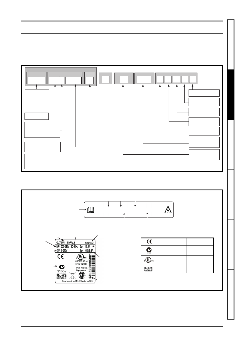
2.1 Model number
The way in which the model numbers for the Unidrive M product range is formed is
illustrated below:
Figure 2-1 Model number
2.2 Nameplate description
Figure 2-2 Typical drive rating labels
Safety information
Product information
Mechanical installation Electrical installation Technical data UL listing information
Unidrive M Frame 5 to 6 Power Installation Guide 11
Refer to Figure 2-1 Model number on page 11 for further information relating to the labels.
Issue Number: 3
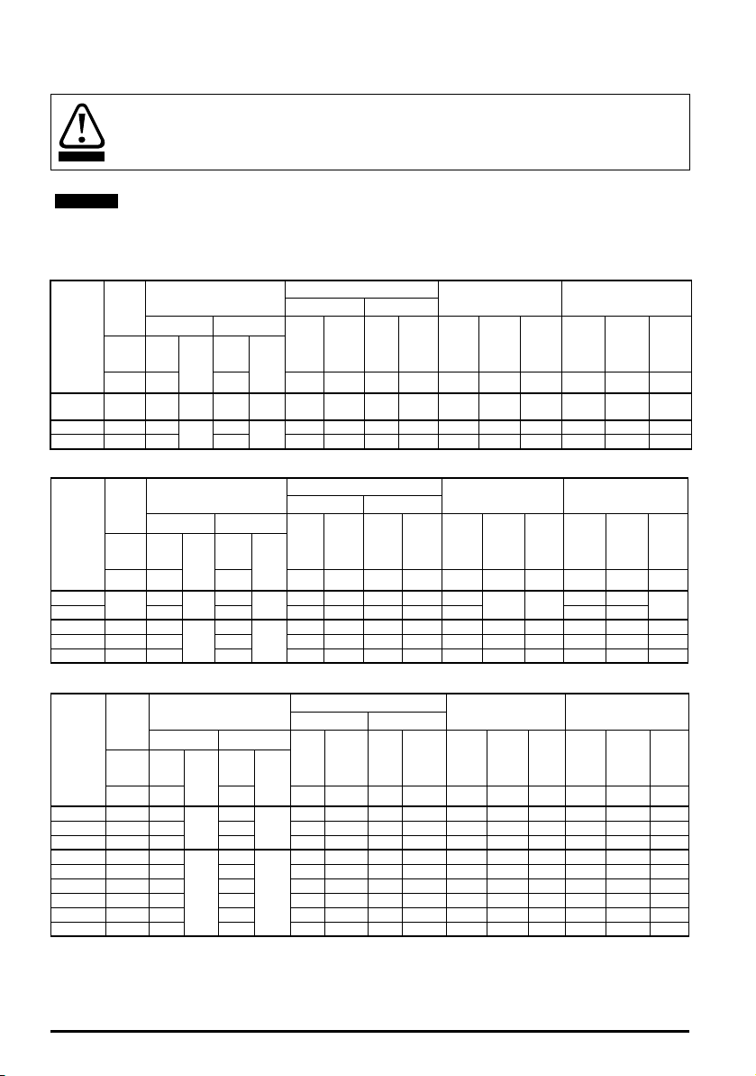
2.3 Ratings
WARNING
NOTE
Fuses
The AC supply to the drive must be installed with suitable protection against overload and
short-circuits. The following section shows recommended fuse ratings. Failure to observe
this requirement will cause risk of fire.
Nominal cables sizes below are based on the cable installation method B2 (ref: IEC603645-52:2001) unless otherwise specified, and are provided as a guide only. Ensure cables
used suit local wiring regulations.
Table 2-1 200 V drive ratings, cable sizes and fuse ratings
Max.
cont.
input
current
Model
05200250 31 40 gG 40
06200330 48.8 63
06200440 56.6 63 70 25 25 3 3 58 15 20 44 11 15
3ph Nom
AA A
Fuse
IEC UL
Nom
Class
60
gG
Class
CC,
J or T*
CC,
J or T*
Nominal cable size
European USA
Input Output Input Output
2
mm2mm
10 10 8 8 30 7.5 10 25 5.5 7.5
16 16 4 4 50 11 15 33 7.5 10
AWG AWG A kW hp A k W hp
Normal Duty Heavy Duty
Max.
Nom
Motor
cont.
output
current
power
@
230 V
power
@
230 V
Max.
cont.
output
current
Nom
power
@
230 V
Table 2-2 400 V drive ratings, cable sizes and fuse ratings
Max.
cont.
input
current
Model
3ph Nom
05400270
05400300 40 35 6 6 8 8 31 30 15
06400350 36 63
06400420 46 63 50 16 16 4 4 48 22 30 42 18.5 30
06400470 60 63 70 25 25 3 3 63 30 40 47 22 30
AA A
29
Fuse
IEC UL
Class
40
gG
gR
Nom
35
40
Class
CC,
J or T*
HSJ or
DFJ
Nominal cable size
European USA
Input Output Input Output
2
mm2mm
668 830
10 10 6 6 38 18.5 25 35 15 25
AWG AWG A kW hp A k W h p
Normal Duty Heavy Duty
Max.
Nom
Motor
cont.
output
current
power
@
400 V
15 20
power
@
460 V
Max.
cont.
output
current
27 11
Nom
power
@
400 V
Motor
power
460 V
Table 2-3 575 V drive ratings, cable sizes and fuse ratings
Max.
cont.
input
current
Model
05500030 4.3 10
05500040 5.7 10 10 1 1 14 14 6.1 4 5 4 2.2 3
05500069 9.3 20 20 1.5 1.5 14 14 10 5.5 7.5 6.9 4 5
06500100 13.2 20
06500150 18.7 32 25 4 4 10 10 17 11 15 15 7.5 10
06500190 24.3 40 30 6 6 10 10 22 15 20 19 11 15
06500230 29.4 50 35 10 10 8 8 27 18.5 25 23 15 20
06500290 37.1 50 40 10 10 6 6 34 22 30 29 18.5 25
06500350 46.9 63 50 16 16 6 6 43 30 40 35 22 30
3ph Nom
AA A
Fuse
IEC UL
Nom
Class
10
gG
20
gG
Class
CC,
J or
CC,
J or
Nominal cable size
European USA
Input Output Input Output
2
mm2mm
0.75 0.75 16 16 3.9 2.2 3 3 1.5 2
T*
2.5 2.5 14 14 12 7.5 10 10 5.5 7.5
T*
AWG AWG A kW hp A kW hp
Normal Duty Heavy Duty
Max.
Nom
Motor
cont.
output
current
power
@
575 V
power
@
575 V
Max.
cont.
output
current
Nom
power
@
575 V
power
* These fuses are fast acting.
Motor
power
@
230 V
@
20
Motor
@
575 V
12 Unidrive M Frame 5 to 6 Power Installation Guide
Issue Number: 3
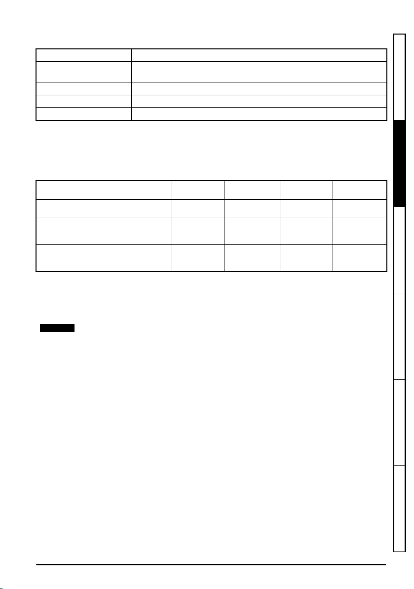
Table 2-4 Protective ground cable ratings
NOTE
Input phase conductor size Minimum ground conductor size
≤ 10 mm
> 10 mm
> 16 mm
> 35 mm
2
2
and ≤ 16 mm
2
and ≤ 35 mm
2
Either 10 mm2 or two conductors of the same cross-sectional area as the input
phase conductor
2
The same cross-sectional area as the input phase conductor
2
2
16 mm
Half of the cross-sectional area of the input phase conductor
Typical short term overload limits
The maximum percentage overload limit changes depending on the selected motor. Variations in
motor rated current, motor power factor and motor leakage inductance all result in changes in the
maximum possible overload. Typical values are shown in the table below:
Table 2-5 Typical overload limits
Operating mode RFC from cold RFC from 100 %
Normal Duty overload with motor rated
current = drive rated current
Heavy Duty overload with motor rated
current = drive rated current (size 8 and
below)
Heavy Duty overload with motor rated
current = drive rated current (size 9E and
10)
Open loop
from cold
110 % for 165 s 110 % for 9 s 110 % for 165 s 110 % for 9 s
200 % for 28 s 200 % for 3 s 150 % for 60 s 150 % for 7 s
175 % for 42 s 175 % for 5 s 150 % for 60 s 150 % for 7 s
Open loop
from 100 %
Generally the drive rated current is higher than the matching motor rated current allowing a higher
level of overload than the default setting.
The time allowed in the overload region is proportionally reduced at very low output frequency on
some drive ratings.
The maximum overload level which can be attained is independent of the speed.
Safety information
Product information
Mechanical installation Electrical installation Technical data UL listing information
Output current
The continuous output current ratings given on the rating label are for maximum 40 °C (104 °F),
1000 m altitude and 3.0 kHz switching frequency. Derating is required for higher switching
frequencies, ambient temperatures >40 °C (104 °F) and higher altitude. For derating information,
refer to the Drive User Guide.
Input current
The input current is affected by the supply voltage and impedance. The input current given on the
rating label is the typical input current and is stated for a balanced supply.
Unidrive M Frame 5 to 6 Power Installation Guide 13
Issue Number: 3
2.4 Drive features
15
14
15
12
12
15
15
14
18
17
16
15
14
12
17 16
18
1
2
3
4
5
6
7
8
9
10
11
13
13
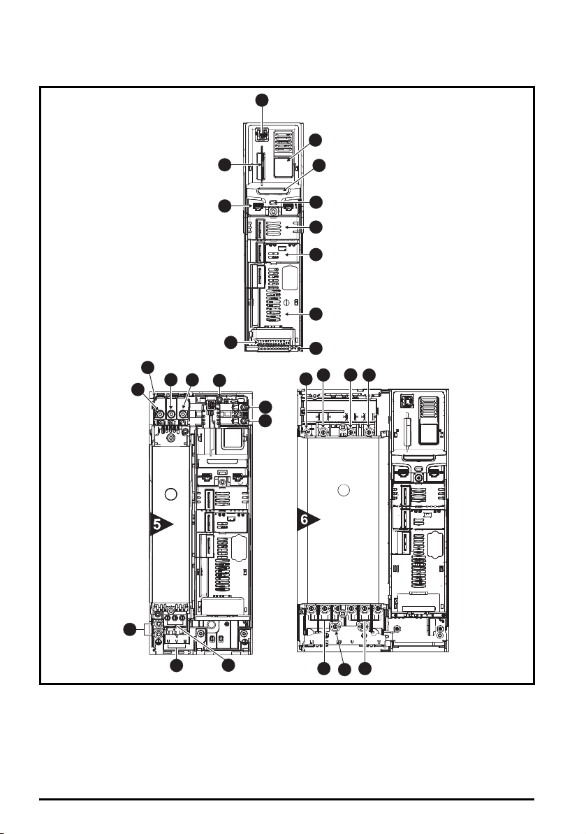
Figure 2-3 Features of the drive (size 3 to 5)
Key
1. Keypad connection 6. Option module slot 2 11. NV media card slot 16. Motor connections
2. Rating label 7. Option module slot 3 12. Braking terminal 17. AC supply connections
3. Identification label 8. Relay connections 13. Internal EMC filter 18. Ground connections
4. Status LED 9. Control connections 14. DC bus +
5. Option module slot 1 10. Communications port 15. DC bus -
14 Unidrive M Frame 5 to 6 Power Installation Guide
Issue Number: 3
 Loading...