

Page 1

Control User Guide
Unidrive M400
Variable Speed AC drive for induction
motors
Part Number: 0478-0349-01
Issue: 1
Page 2

Original Instructions
For the purposes of compliance with the EU Machinery Directive 2006/42/EC:
General information
The manufacturer accepts no liability for any consequences resulting from inappropriate, negligent or incorrect installation or
adjustment of the optional operating parameters of the equipment or from mismatching the variable speed drive with the motor.
The contents of this guide are believed to be correct at the time of printing. In the interests of a commitment to a policy of continuous
development and improvement, the manufacturer reserves the right to change the specification of the product or its performance, or
the contents of the guide, without notice.
All rights reserved. No part of this guide may be reproduced or transmitted in any form or by any means, electrical or mechanical
including photocopying, recording or by an information storage or retrieval system, without permission in writing from the publisher.
Drive firmware version
This product is supplied with the latest firmware version. If this drive is to be connected to an existing system or machine, all drive
firmware versions should be verified to confirm the same functionality as drives of the same model already present. This may also
apply to drives returned from an Emerson Industrial Automation Service Centre or Repair Centre. If there is any doubt please contact
the supplier of the product.
The firmware version of the drive can be checked by looking at Pr 11.029 and Pr 11.035.
Environmental statement
Emerson Industrial Automation is committed to minimising the environmental impacts of its manufacturing operations and of its
products throughout their life cycle. To this end, we operate an Environmental Management System (EMS) which is certified to the
International Standard ISO 14001. Further information on the EMS, our Environmental Policy and other relevant information is
available on request, or can be found at
http://www.emersonindustrial.com/en-EN/controltechniques/aboutus/environment/Pages/environment.aspx
The electronic variable-speed drives manufactured by Emerson Industrial Automation have the potential to save energy and (through
increased machine/process efficiency) reduce raw material consumption and scrap throughout their long working lifetime. In typical
applications, these positive environmental effects far outweigh the negative impacts of product manufacture and end-of-life disposal.
Nevertheless, when the products eventually reach the end of their useful life, they must not be discarded but should instead be
recycled by a specialist recycler of electronic equipment. Recyclers will find the products easy to dismantle into their major component
parts for efficient recycling. Many parts snap together and can be separated without the use of tools, while other parts are secured
with conventional fasteners. Virtually all parts of the product are suitable for recycling.
Product packaging is of good quality and can be re-used. Large products are packed in wooden crates, while smaller products come
in strong cardboard cartons which themselves have a high recycled fibre content. If not re-used, these containers can be recycled.
Polythene, used on the protective film and bags for wrapping product, can be recycled in the same way. Emerson Industrial
Automations' packaging strategy prefers easily-recyclable materials of low environmental impact, and regular reviews identify
opportunities for improvement.
When preparing to recycle or dispose of any product or packaging, please observe local legislation and best practice.
REACH legislation
EC Regulation 1907/2006 on the Registration, Evaluation, Authorisation and restriction of Chemicals (REACH) requires the supplier
of an article to inform the recipient if it contains more than a specified proportion of any substance which is considered by the European
Chemicals Agency (ECHA) to be a Substance of Very High Concern (SVHC) and is therefore listed by them as a candidate for
compulsory authorisation.
For current information on how this requirement applies in relation to specific Emerson Industrial Automations' products, please
approach your usual contact in the first instance. Emerson Industrial Automations' position statement can be viewed at:
www.emersonindustrial.com/en-EN/controltechniques/aboutus/environment/reachregulation/Pages/reachregulation.aspx
Copyright © May 2016 Emerson Industrial Automation.
The information contained in this guide is for guidance only and does not form part of any contract. The accuracy cannot be guaranteed
as Emerson have an ongoing process of development and reserve the right to change the specification of their products without notice.
Control Techniques Limited. Registered Office: The Gro, Newtown, Powys SY16 3BE. Registered in England and Wales. Company
Reg. No. 01236886.
Moteurs Leroy-Somer SAS. Headquarters: Bd Marcellin Leroy, CS 10015, 16915 Angoulême Cedex 9, France. Share Capital: 65 800
512 €, RCS Angoulême 338 567 258.
Issue Number: 1
Drive Firmware: 01.04.04 onwards
For patent and intellectual property related information please go to: www.ctpatents.info.
Page 3
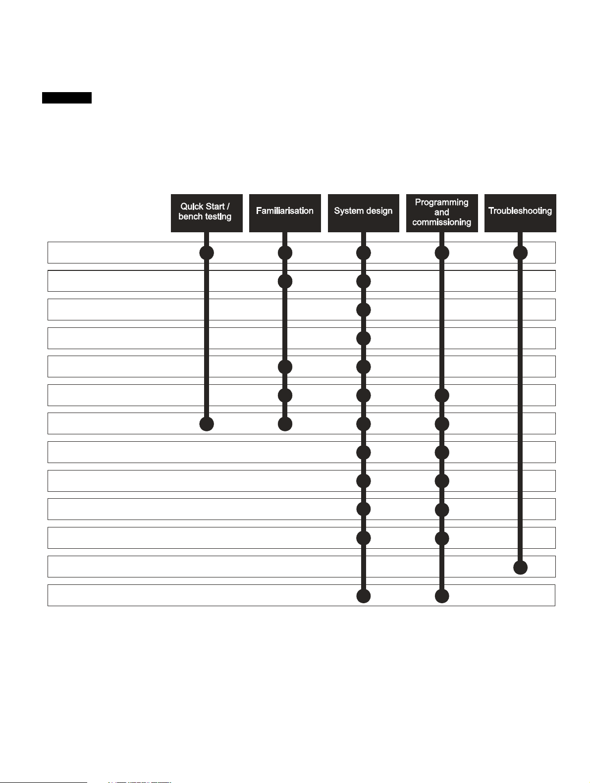
How to use this guide
NOTE
1 Safety information
2 Product information
3 Mechanical installation
4 Electrical installation
5 Getting started
6 Basic parameters
7 Running the motor
8 Optimization
9 NV media card operation
11 Advanced parameters
10 Onboard PLC
12 Diagnostics
13 UL listing information
This guide is intended to be used in conjunction with the appropriate Power Installation Guide. The Power Installation
Guide gives information necessary to physically install the drive. This guide gives information on drive configuration,
operation and optimization.
There are specific safety warnings throughout this guide, located in the relevant sections. In addition, Chapter 1 Safety
information contains general safety information. It is essential that the warnings are observed and the information
considered when working with or designing a system using the drive.
This map of the user guide helps to find the right sections for the task you wish to complete, but for specific information,
refer to Contents on page 4:
Page 4

Contents
1 Safety information .................................9
1.1 Warnings, Cautions and Notes .............................9
1.2 Electrical safety - general warning ........................9
1.3 System design and safety of personnel ................9
1.4 Environmental limits ..............................................9
1.5 Access ...................................................................9
1.6 Fire protection .......................................................9
1.7 Compliance with regulations .................................9
1.8 Motor .....................................................................9
1.9 Mechanical brake control ......................................9
1.10 Adjusting parameters ............................................9
1.11 Electrical installation ............................................10
1.12 Hazard .................................................................10
2 Product information ............................11
2.1 Introduction .........................................................11
2.2 Model number .....................................................11
2.3 Ratings ................................................................12
2.4 Operating modes .................................................13
2.5 Keypad and display .............................................13
2.6 Nameplate description ........................................14
2.7 Options ................................................................15
3 Mechanical installation .......................18
3.1 Installing / removing options and keypad ............18
3.2 Real time clock battery replacement ...................21
4 Electrical installation ...........................22
4.1 24 Vdc supply ......................................................22
4.2 Communication connections ...............................22
4.3 Control connections ............................................23
4.4 Safe Torque Off (STO) ........................................27
5 Getting started .....................................29
5.1 Understanding the display ...................................29
5.2 Keypad operation ................................................29
5.3 Menu structure ....................................................31
5.4 Advanced menus ................................................32
5.5 Changing the operating mode .............................33
5.6 Saving parameters ..............................................33
5.7 Restoring parameter defaults ..............................33
5.8 Parameter access level and security ..................33
5.9 Displaying parameters with non-default
values only ..........................................................34
5.10 Displaying destination parameters only ..............34
5.11 Communications .................................................34
6 Basic parameters .................................35
6.1 Menu 0: Basic parameters ..................................36
6.2 Parameter descriptions .......................................40
6.3 Control terminal configurations and wiring ..........41
7 Running the motor ..............................47
7.1 Quick start connections .......................................47
7.2 Changing the operating mode .............................47
7.3 Quick start commissioning / start-up ...................52
8 Optimization ........................................ 54
8.1 Motor map parameters ....................................... 54
8.2 Maximum motor rated current ............................ 60
8.3 Current limits ...................................................... 60
8.4 Motor thermal protection .................................... 60
8.5 Switching frequency ........................................... 61
8.6 CT Modbus RTU specification ........................... 62
9 NV Media Card Operation .................. 67
9.1 Introduction ........................................................ 67
9.2 SD card support ................................................. 67
9.3 NV Media Card parameters ............................... 70
9.4 NV Media Card trips ........................................... 70
9.5 Data block header information ........................... 70
10 Onboard PLC ....................................... 71
10.1 Onboard PLC and Machine Control Studio ........ 71
10.2 Benefits .............................................................. 71
10.3 Features ............................................................. 71
10.4 Onboard PLC parameters .................................. 72
10.5 Onboard PLC trips ............................................. 72
11 Advanced parameters ........................ 73
11.1 Parameter ranges and Variable minimum/
maximums: ......................................................... 76
11.2 Menu 1: Frequency reference ............................ 82
11.3 Menu 2: Ramps .................................................. 86
11.4 Menu 3: Frequency control ................................ 89
11.5 Menu 4: Torque and current control ................... 94
11.6 Menu 5: Motor control ........................................ 97
11.7 Menu 6: Sequencer and clock .......................... 101
11.8 Menu 7: Analog I/O .......................................... 103
11.9 Menu 8: Digital I/O ........................................... 106
11.10 Menu 9: Programmable logic, motorized pot,
binary sum and timers ...................................... 112
11.11 Menu 10: Status and trips ................................ 118
11.12 Menu 11: General drive set-up ......................... 120
11.13 Menu 12: Threshold detectors, variable
selectors and brake control function ................ 122
11.14 Menu 14: User PID controller ........................... 128
11.15 Menu 15: Option module set-up ....................... 131
11.16 Menu 18: Application menu 1 ........................... 132
11.17 Menu 20: Application menu 2 ........................... 133
11.18 Menu 21: Second motor parameters ................ 134
11.19 Menu 22: Additional Menu 0 set-up ................. 135
12 Diagnostics ....................................... 137
12.1 Status modes (Keypad and LED status) .......... 137
12.2 Trip indications ................................................. 137
12.3 Identifying a trip / trip source ............................ 137
12.4 Trips, Sub-trip numbers .................................... 139
12.5 Internal / Hardware trips ................................... 158
12.6 Alarm indications .............................................. 158
12.7 Status indications ............................................. 159
12.8 Displaying the trip history ................................. 159
12.9 Behaviour of the drive when tripped ................. 160
4 Unidrive M400 Control User Guide
Issue Number: 1
Page 5

13 UL information ...................................161
13.1 UL file reference ................................................161
13.2 Option modules, kits and accessories ..............161
13.3 Enclosure ratings ..............................................161
13.4 Mounting ...........................................................161
13.5 Environment ......................................................161
13.6 Electrical Installation .........................................161
13.7 Motor overload protection and thermal
memory retention ..............................................162
13.8 Electrical supply ................................................162
13.9 External Class 2 supply ....................................162
13.10 Requirement for Transient Surge Suppression .162
13.11 Group Installation and Modular Drive Systems .162
Unidrive M400 Control User Guide 5
Issue Number: 1
Page 6
EU Declaration of Conformity
Control Techniques Ltd
The Gro
Newtown
Powys
UK
SY16 3BE
This declaration is issued under the sole responsibility of the manufacturer. The object of the declaration is in conformity with the relevant Union
harmonization legislation. The declaration applies to the variable speed drive products shown below:
Model number Interpretation Nomenclature aaaa - bbc ddddde
aaaa Basic series
bb Frame size 01, 02, 03, 04, 05, 06, 07, 08, 09, 10, 11
c Voltage rating 1 = 100 V, 2 = 200 V, 4 = 400 V, 5 = 575 V, 6 = 690 V
ddddd Current rating Example 01000 = 100 A
e Drive format
The model number may be followed by additional characters that do not affect the ratings.
The variable speed drive products listed above have been designed and manufactured in accordance with the following European harmonized
standards:
EN 61800-5-1:2007 Adjustable speed electrical power drive systems - Part 5-1: Safety requirements - Electrical, thermal and energy
EN 61800-3: 2004+A1:2012 Adjustable speed electrical power drive systems - Part 3: EMC requirements and specific test methods
EN 61000-6-2:2005 Electromagnetic compatibility (EMC) - Part 6-2: Generic standards - Immunity for industrial environments
EN 61000-6-4: 2007+ A1:2011
EN 61000-3-2:2014
EN 61000-3-3:2013
EN 61000-3-2:2014 Applicable where input current < 16 A. No limits apply for professional equipment where input power ≥1 kW.
These products comply with the Restriction of Hazardous Substances Directive (2011/65/EU), the Low Voltage Directive (2014/35/EU) and the
Electromagnetic Compatibility Directive (2014/30/EU).
M100, M101, M200, M201, M300, M400, M600, M700, M701, M702, F300, H300, E200,E300, HS30, HS70,
HS71, HS72, M000, RECT
A = 6P Rectifier + Inverter (internal choke), D = Inverter, E = 6P Rectifier + Inverter (external choke),
T = 12P Rectifier + Inverter (external choke)
Electromagnetic compatibility (EMC) - Part 6-4: Generic standards - Emission standard for industrial
environments
Electromagnetic compatibility (EMC) - Part 3-2: Limits for harmonic current emissions (equipment input current
16 A per phase)
Electromagnetic compatibility (EMC) - Part 3-3: Limitation of voltage changes, voltage fluctuations and flicker in
public, low voltage supply systems, for equipment with rated current 16 A per phase and not subject to
conditional connection
Moteurs Leroy-Somer
Usine des Agriers
Boulevard Marcellin Leroy
CS10015
16915 Angoulême Cedex 9
France
G Williams
Vice President, Technology
Date: 17th March 2016
These electronic drive products are intended to be used with appropriate motors, controllers, electrical protection components and other
equipment to form complete end products or systems. Compliance with safety and EMC regulations depends upon installing and
configuring drives correctly, including using the specified input filters.
The drives must be installed only by professional installers who are familiar with requirements for safety and EMC. Refer to the Product
Documentation. An EMC data sheet is available giving detailed information. The assembler is responsible for ensuring that the end product
or system complies with all the relevant laws in the country where it is to be used.
6 Unidrive M400 Control User Guide
Issue Number: 1
Page 7

EU Declaration of Conformity (including 2006 Machinery Directive)
Control Techniques Ltd
The Gro
Newtown
Powys
UK
SY16 3BE
This declaration is issued under the sole responsibility of the manufacturer. The object of the declaration is in conformity with the relevant Union
harmonization legislation. The declaration applies to the variable speed drive products shown below:
Model No. Interpretation Nomenclature aaaa - bbc ddddde
aaaa Basic series M300, M400, M600, M700, M701, M702, F300, H300, E200, E300, HS30, HS70, HS71, HS72, M000, RECT
bb Frame size 01, 02, 03, 04, 05, 06, 07, 08, 09, 10, 11
c Voltage rating 1 = 100 V, 2 = 200 V, 4 = 400 V, 5 = 575 V, 6 = 690 V
ddddd Current rating Example 01000 = 100 A
e Drive format
The model number may be followed by additional characters that do not affect the ratings.
This declaration relates to these products when used as a safety component of a machine. Only the Safe Torque Off function may be used
for a safety function of a machine. None of the other functions of the drive may be used to carry out a safety function.
These products fulfil all the relevant provisions of the Machinery Directive 2006/42/EC and the Electromagnetic Compatibility Directive (2014/30/EU).
EC type examination has been carried out by the following notified body:
TUV Rheinland Industrie Service GmbH
Am Grauen Stein
D-51105 Köln
Germany
A = 6P Rectifier + Inverter (internal choke), D = Inverter, E = 6P Rectifier + Inverter (external choke),
T = 12P Rectifier + Inverter (external choke)
Moteurs Leroy-Somer
Usine des Agriers
Boulevard Marcellin Leroy
CS10015
16915 Angoulême Cedex 9
France
EC type-examination certificate numbers:
01/205/5270.01/14 dated 2014-11-11
01/205/5387.01/15 dated 2015-01-29
01/205/5383.02/15 dated 2015-04-21
Notified body identification number: 0035
The harmonized standards used are shown below:
EN 61800-5-1:2007 Adjustable speed electrical power drive systems - Part 5-1: Safety requirements - Electrical, thermal and energy
EN 61800-5-2:2007 Adjustable speed electrical power drive systems - Part 5-2: Safety requirements - Functional
EN ISO 13849-1:2008 Safety of Machinery, Safety-related parts of control systems, General principles for design
EN ISO 13849-2:2008 Safety of machinery, Safety-related parts of control systems. Validation
EN 61800-3: 2004+A1:2012 Adjustable speed electrical power drive systems - Part 3: EMC requirements and specific test methods
EN 62061:2005
Person authorised to complete the technical file:
P Knight
Conformity Engineer
Newtown, Powys, UK
Safety of machinery, Functional safety of safety related electrical, electronic and programmable electronic control
systems
Unidrive M400 Control User Guide 7
Issue Number: 1
Page 8

G. Williams
Vice President, Technology
Date: 17th March 2016
Place: Newtown, Powys, UK
IMPORTANT NOTICE
These electronic drive products are intended to be used with appropriate motors, controllers, electrical protection components and other
equipment to form complete end products or systems. Compliance with safety and EMC regulations depends upon installing and
configuring drives correctly, including using the specified input filters.
The drives must be installed only by professional installers who are familiar with requirements for safety and EMC. Refer to the Product
Documentation. An EMC data sheet is available giving detailed information. The assembler is responsible for ensuring that the end product
or system complies with all the relevant laws in the country where it is to be used.
8 Unidrive M400 Control User Guide
Issue Number: 1
Page 9

Safety
WARNING
CAUTION
NOTE
information
Product
information
Mechanical
installation
Electrical
installation
Getting
started
Basic
parameters
Running
the motor
Optimization
NV Media Card
Operation
Onboard
PLC
Advanced
parameters
Diagnostics
UL
information
1 Safety information
1.1 Warnings, Cautions and Notes
A Warning contains information which is essential for
avoiding a safety hazard.
A Caution contains information which is necessary for
avoiding a risk of damage to the product or other equipment.
A Note contains information which helps to ensure correct operation of
the product.
1.2 Electrical safety - general warning
The voltages used in the drive can cause severe electrical shock and/or
burns, and could be lethal. Extreme care is necessary at all times when
working with or adjacent to the drive.
Specific warnings are given at the relevant places in this Control User
Guide
1.3 System design and safety of
The drive is intended as a component for professional incorporation into
complete equipment or a system. If installed incorrectly, the drive may
present a safety hazard.
The drive uses high voltages and currents, carries a high level of stored
electrical energy, and is used to control equipment which can cause
injury.
Close attention is required to the electrical installation and the system
design to avoid hazards either in normal operation or in the event of
equipment malfunction. System design, installation, commissioning/
start-up and maintenance must be carried out by personnel who have
the necessary training and experience. They must read this safety
information and this Control User Guide carefully.
The STOP and Safe Torque Off functions of the drive do not isolate
dangerous voltages from the output of the drive or from any external
option unit. The supply must be disconnected by an approved electrical
isolation device before gaining access to the electrical connections.
With the sole exception of the Safe Torque Off function, none of the
drive functions must be used to ensure safety of personnel, i.e.
they must not be used for safety-related functions.
Careful consideration must be given to the functions of the drive which
might result in a hazard, either through their intended behavior or
through incorrect operation due to a fault. In any application where a
malfunction of the drive or its control system could lead to or allow
damage, loss or injury, a risk analysis must be carried out, and where
necessary, further measures taken to reduce the risk - for example, an
over-speed protection device in case of failure of the speed control, or a
fail-safe mechanical brake in case of loss of motor braking.
The Safe Torque Off function may be used in a safety-related
application. The system designer is responsible for ensuring that the
complete system is safe and designed correctly according to the
relevant safety standards.
personnel
1.5 Access
Drive access must be restricted to authorized personnel only. Safety
regulations which apply at the place of use must be complied with.
1.6 Fire protection
The drive enclosure is not classified as a fire enclosure. A separate fire
enclosure must be provided. For further information, refer to the relevant
Power Installation Guide.
1.7 Compliance with regulations
The installer is responsible for complying with all relevant regulations,
such as national wiring regulations, accident prevention regulations and
electromagnetic compatibility (EMC) regulations. Particular attention
must be given to the cross-sectional areas of conductors, the selection
of fuses or other protection, and protective ground (earth) connections.
The Power Installation Guide contains instruction for achieving
compliance with specific EMC standards.
Within the European Union, all machinery in which this product is used
must comply with the following directives:
Safety of Machinery 2006/42/EC.
Electromagnetic Compatibility (EMC) Directive 2014/30/EU.
1.8 Motor
Ensure the motor is installed in accordance with the manufacturer’s
recommendations. Ensure the motor shaft is not exposed.
Standard squirrel cage induction motors are designed for single speed
operation. If it is intended to use the capability of the drive to run a motor
at speeds above its designed maximum, it is strongly recommended that
the manufacturer is consulted first.
Low speeds may cause the motor to overheat because the cooling fan
becomes less effective. The motor should be installed with a protection
thermistor. If necessary, an electric forced vent fan should be used.
The values of the motor parameters set in the drive affect the protection
of the motor. The default values in the drive should not be relied upon.
It is essential that the correct value is entered in Pr 00.006 motor rated
current. This affects the thermal protection of the motor.
1.9 Mechanical brake control
The brake control functions are provided to allow well co-ordinated
operation of an external brake with the drive. While both hardware and
software are designed to high standards of quality and robustness, they
are not intended for use as safety functions, i.e. where a fault or failure
would result in a risk of injury. In any application where the incorrect
operation of the brake release mechanism could result in injury,
independent protection devices of proven integrity must also be
incorporated.
1.10 Adjusting parameters
Some parameters have a profound effect on the operation of the drive.
They must not be altered without careful consideration of the impact on
the controlled system. Measures must be taken to prevent unwanted
changes due to error or tampering.
1.4 Environmental limits
Instructions in the Power Installation Guide regarding transport, storage,
installation and use of the drive must be complied with, including the
specified environmental limits. Drives must not be subjected to
excessive physical force.
Unidrive M400 Control User Guide 9
Issue Number: 1
Page 10

Safety
information
Product
information
Mechanical
installation
Electrical
installation
Getting
started
Basic
parameters
Running
the motor
1.11 Electrical installation
1.11.1 Electric shock risk
The voltages present in the following locations can cause severe electric
shock and may be lethal:
AC supply cables and connections
Output cables and connections
Many internal parts of the drive, and external option units
Unless otherwise indicated, control terminals are single insulated and
must not be touched.
1.11.2 Stored charge
The drive contains capacitors that remain charged to a potentially lethal
voltage after the AC supply has been disconnected. If the drive has been
energized, the AC supply must be isolated at least ten minutes before
work may continue.
1.12 Hazard
1.12.1 Falling hazard
The drive presents a falling or toppling hazard. This can cause injury to
personnel and therefore should be handled with care.
Optimization
NV Media Card
Operation
Onboard
PLC
Advanced
parameters
Diagnostics
UL
information
10 Unidrive M400 Control User Guide
Issue Number: 1
Page 11
Safety
Optional Build
Identification Label
Derivative Electrical Specifications
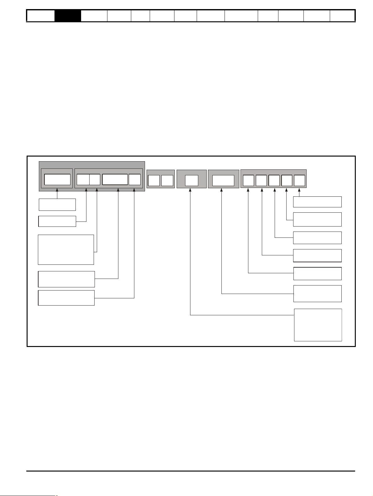
M400 - 03 4 00073
Unidrive M400
Product Line
Frame Size
:
Voltage Rating:
Current Rating:
Heavy Duty current rating x 10
Drive Format:
A - AC in AC out
Customer Code
01
A B 1 00
Customer Code:
00 = 50 Hz
01 = 60 Hz
Reserved:
Conformal Coating:
0 = Standard
IP / NEMA Rating:
1 = IP20 / NEMA 1
Brake Transistor
:
B=
Brake
Cooling:
A = Air
Reserved
01
A
Documentation
1
Documentation:
2 - 200 V (200 - 240
- 400 V (380 - 480
- 575 V (500 - 575
- 690 V (500 - 690
± 10 %)
4
1 - 100 V (100 - 120 10 %)±
±±10 %)
5
6 10 %)
± 10 %)
0 - Supplied separately
1 - English
2 - French
3 - Italian
4 - German
5 - Spanish
N = No
information
Product
information
Mechanical
installation
Electrical
installation
Getting
started
Basic
parameters
Running
the motor
Optimization
NV Media Card
Operation
Onboard
PLC
Advanced
parameters
Diagnostics
information
2 Product information
2.1 Introduction
Open loop AC drive
Unidrive M400 delivers maximum machine performance with open loop vector and sensorless induction motor control, for dynamic and efficient
machine operation.
Features
• Fast set-up and diagnosis with real-text display
• Onboard IEC 61131-3 programmable automation
• NV Media Card for parameter copying and data storage
• 24 Vdc Back-up supply (optional)
• EIA 485 serial communications interface (optional)
• Dual channel Safe Torque Off (STO) input
2.2 Model number
The way in which the model numbers for the Unidrive M range are formed is illustrated below:
Figure 2-1 Model number
UL
Unidrive M400 Control User Guide 11
Issue Number: 1
Page 12
Safety
Available output
current
Overload limit -
Heavy Duty
Maximum
continuous
current (above
50% base
speed) -
Normal Duty
Maximum
continuous
current -
Heavy Duty
Motor rated
current set
in the drive
Heavy Duty
- with high
overload capability
Normal Duty
Overload limit -
Normal Duty
NOTE
NOTE
Motor total
current (Pr 04.001)
as a percentage
of motor rated
current
Motor speed as a
percentage of base speed
100%
Max. permissible
continuous
current
100%
I t protection operates in this region
2
70%
50%15%
Pr = 0
Pr = 1
04.025
04.025
Motor total
current (Pr 04.001)
as a percentage
of motor rated
current
Motor speed as a
percentage of base speed
100%
Max. permissible
continuous
current
100%
I t protection operates in this region
2
70%
50%
Pr = 0
Pr = 1
04.025
04.025
information
Product
information
Mechanical
installation
Electrical
installation
Getting
started
Basic
parameters
Running
the motor
Optimization
NV Media Card
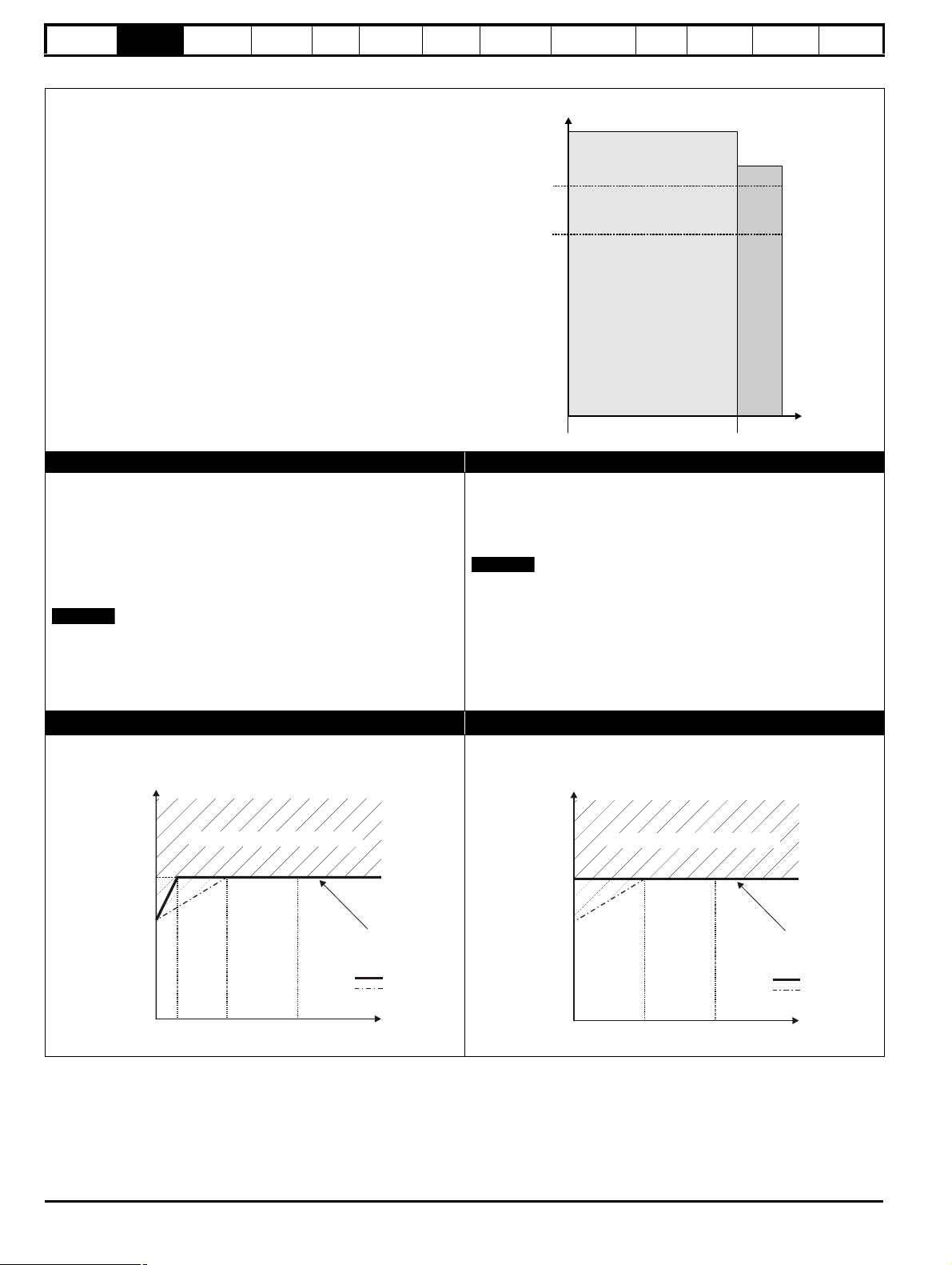
2.3 Ratings
The size 1 to 4 drive is Heavy Duty rated only.
The size 5 to 9 drive is dual rated.
The setting of the motor rated current determines which rating applies Heavy Duty or Normal Duty.
The two ratings are compatible with motors designed to IEC60034.
The graph aside illustrates the difference between Normal Duty and
Heavy Duty with respect to continuous current rating and short term
overload limits.
Normal Duty Heavy Duty (default)
For applications which use Self ventilated (TENV/TEFC) induction
motors and require a low overload capability, and full torque at low
speeds is not required (e.g. fans, pumps).
Self ventilated (TENV/TEFC) induction motors require increased
protection against overload due to the reduced cooling effect of the fan
at low speed. To provide the correct level of protection the I
2
t software
operates at a level which is speed dependent. This is illustrated in the
graph below.
The speed at which the low speed protection takes effect can be
changed by the setting of Low Speed Thermal Protection Mode
(04.025). The protection starts when the motor speed is below 15 % of
base speed when Pr 04.025 = 0 (default) and below 50 % when
Pr 04.025 = 1.
Operation of motor I2t protection
Motor I2t protection is fixed as shown below and is compatible with:
• Self ventilated (TENV/TEFC) induction motors
For constant torque applications or applications which require a high
overload capability, or full torque is required at low speeds (e.g. winders,
hoists).
The thermal protection is set to protect force ventilated induction motors
by default.
N
If the application uses a self ventilated (TENV/TEFC) induction motor
and increased thermal protection is required for speeds below 50 %
base speed, then this can be enabled by setting Low Speed Thermal
Protection Mode (04.025) = 1.
Motor I2t protection defaults to be compatible with:
• Forced ventilation induction motors
Operation
Onboard
PLC
Advanced
parameters
Diagnostics
UL
information
12 Unidrive M400 Control User Guide
Issue Number: 1
Page 13
Safety
4
2
3
1
6
5
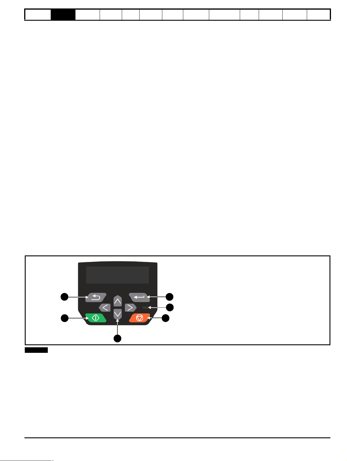
1. Escape button
2. Start button (Green)
3. Navigation keys (x4)
4. Stop / Reset button (red)
5. Status LED
6. Enter button
NOTE
information
Product
information
Mechanical
installation
Electrical
installation
Getting
started
Basic
parameters
Running
the motor
Optimization
NV Media Card
Operation
Onboard
PLC
Advanced
parameters
Diagnostics
UL
information
2.4 Operating modes
The drive is designed to operate in any of the following modes:
1. Open loop mode
Open loop vector mode
Fixed V/F mode (V/Hz)
Square V/F mode (V/Hz)
2. RFC - A
Without position feedback sensor
2.4.1 Open loop mode
The drive applies power to the motor at frequencies varied by the user. The motor speed is a result of the output frequency of the drive and slip due
to the mechanical load. The drive can improve the speed control of the motor by applying slip compensation. The performance at low speed depends
on whether V/F mode or open loop vector mode is selected.
Open loop vector mode
The voltage applied to the motor is directly proportional to the frequency except at low speed where the drive uses motor parameters to apply the
correct voltage to keep the flux constant under varying load conditions.
Typically 100 % torque is available down to 1 Hz for a 50 Hz motor.
Fixed V/F mode
The voltage applied to the motor is directly proportional to the frequency except at low speed where a voltage boost is provided which is set by the
user. This mode can be used for multi-motor applications.
Typically 100 % torque is available down to 4 Hz for a 50 Hz motor.
Square V/F mode
The voltage applied to the motor is directly proportional to the square of the frequency except at low speed where a voltage boost is provided which is
set by the user. This mode can be used for running fan or pump applications with quadratic load characteristics or for multi-motor applications. This
mode is not suitable for applications requiring a high starting torque.
2.4.2 RFC-A mode
Rotor Flux Control for Asynchronous (induction) motors (RFC-A) encompasses closed loop vector control without a position feedback device.
Rotor flux control provides closed loop control without the need for position feedback by using current, voltages and key motor parameters to estimate
the motor speed. It can eliminate instability traditionally associated with open loop control for example when operating large motors with light loads at
low frequencies.
2.5 Keypad and display
The keypad and display provide information to the user regarding the operating status of the drive and trip codes, and provide the means for changing
parameters, stopping and starting the drive, and the ability to perform a drive reset.
Figure 2-2 CI-Keypad
The keypad is not supplied with the drive.
Unidrive M400 Control User Guide 13
Issue Number: 1
Page 14
Safety
Model number
Refer to
User Guide
Date code
Input
voltage
Power rating
M400-022 00042 A
200-240V 0.75kW
V40
Model
number
Input voltage
Output
voltage
Serial
number
Input
frequency
Power
rating
Date code
No. of phases &
Typical input current
Heavy duty
output current
Approvals
M400-022 00042 A
0.75kW
10.4A / 5.4A
Patents: www.ctpatents.info
Manuals: www.ctmanuals.info
0-550Hz
Output
frequency
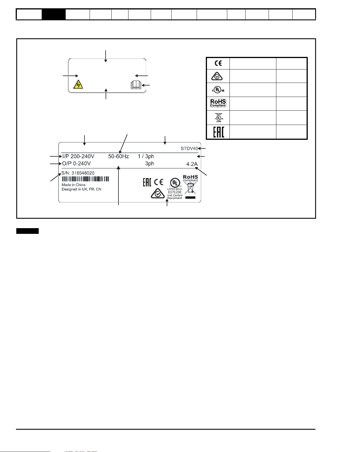
CE approval Europe
RCM - Regulatory
Compliance Mark
Australia
UL / cUL approval
USA &
Canada
RoHS compliant Europe
Functional safety
USA &
Canada
EurAsian Conformity EurAsia
R
Key to approvals
NOTE
information
Product
information
Mechanical
installation
Electrical
installation
2.6 Nameplate description
Figure 2-3 Typical drive rating labels size 2
Getting
started
Basic
parameters
Running
the motor
Optimization
NV Media Card
Operation
Onboard
PLC
Advanced
parameters
Diagnostics
UL
information
Refer to Figure 2-1 Model number on page 11 for further information relating to the labels.
Date code format
The date code is split into two sections: a letter followed by a number. The letter indicates the year, and the number indicates the week number (within
the year) in which the drive was built.The letters go in alphabetical order, starting with A in 1991 (B in 1992, C in 1993 etc).
Example:
A date code of W28 would correspond to week 28 of year 2013.
14 Unidrive M400 Control User Guide
Issue Number: 1
Page 15
Safety
4
6
1
3
3
2
5
7
information
Product
information
Mechanical
installation
Electrical
installation
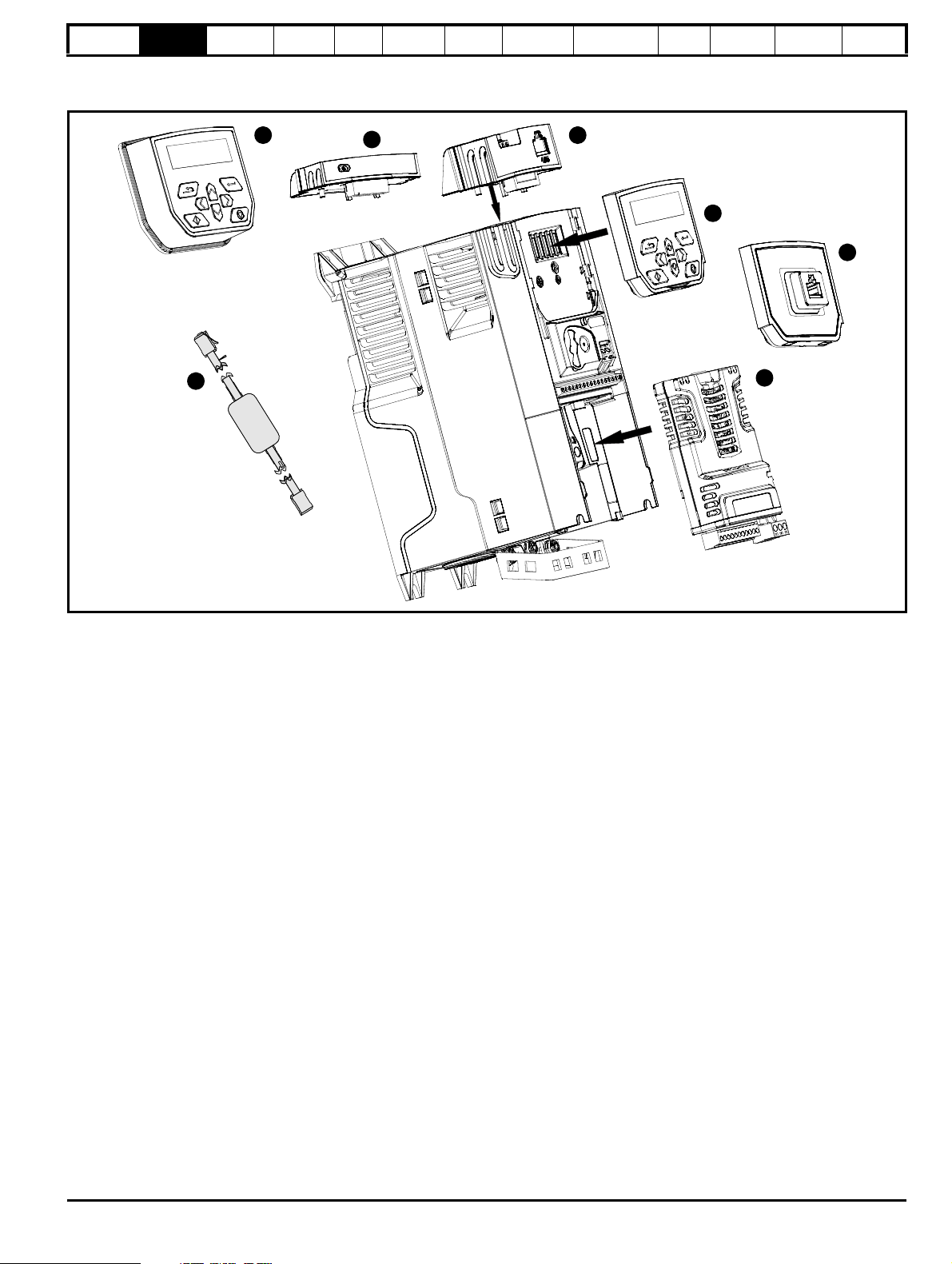
2.7 Options
Figure 2-4 Options available with the drive
Getting
started
Basic
parameters
Running
the motor
Optimization
NV Media Card
Operation
Onboard
PLC
Advanced
parameters
Diagnostics
UL
information
1. Remote mountable LCD keypad
2. AI-Backup adaptor
3. AI-485 Adaptor
4. Compact Interface (CI) keypad
5. CI-485 Adaptor interface
6. System Integration (SI) module
7. CT USB Comms cable
Unidrive M400 Control User Guide 15
Issue Number: 1
Page 16
Safety
information
Product
information
Mechanical
installation
Electrical
installation
Getting
started
Basic
parameters
Running
the motor
Optimization
NV Media Card
Operation
Onboard
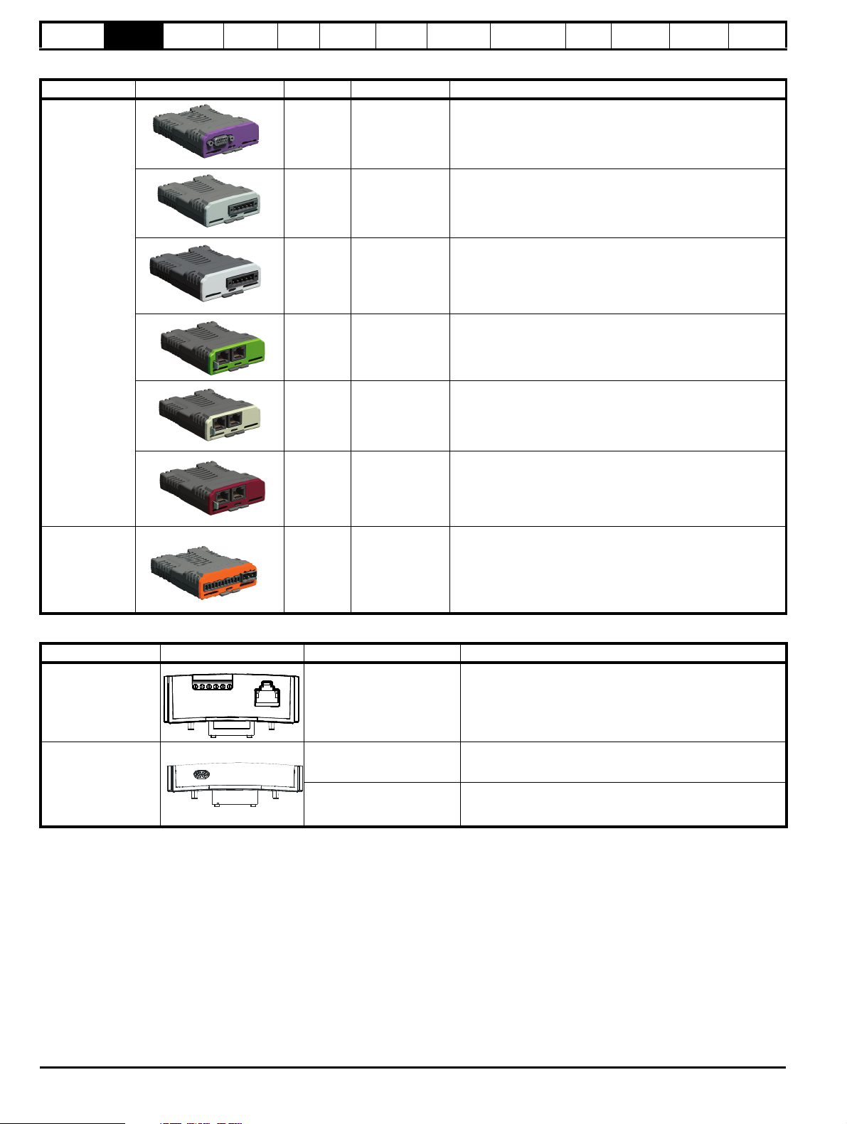
Table 2-1 System Integration (SI) option module identification
Type Option module Color Name Further details
PLC
Advanced
parameters
Diagnostics
UL
information
Fieldbus
Automation
(I/O expansion)
Purple SI-PROFIBUS
Medium
Grey
SI-DeviceNet
Light Grey SI-CANopen
Yellow
Green
SI-PROFINET V2
Beige SI-Ethernet
Brown Red SI-EtherCAT
Orange SI-I/O
Profibus option
PROFIBUS adaptor for communications with the drive
DeviceNet option
DeviceNet adaptor for communications with the drive
CANopen option
CANopen adaptor for communications with the drive
PROFINET V2 option
PROFINET V2 adapter for communications with the drive
External Ethernet module that supports EtherNet/IP, Modbus
TCP/IP and RTMoE. The module can be used to provide global
connectivity and integration with IT network technologies, such as
wireless networking
EtherCAT option
EtherCAT adapter for communications with the drive
Extended I/O
Increases the I/O capability by adding the following combinations:
• Digital I/O
• Digital Inputs
• Analog Inputs (differential or single ended)
• Relays
Table 2-2 Adaptor Interface (AI) option module identification
Type Option module Name Further details
Communications AI-485 adaptor
AI-Backup adaptor
Backup
AI-Smart adaptor
EIA 485 serial communications option
Provides a EIA 485 serial communications interface via an RJ45
connector or alternative screw terminals.
+24 V Backup and SD card interface
Provides a +24 V Backup supply input and SD card interface
+24 V Backup and SD card interface
Supplied with 4 GB SD Card for parameter copying and
application programs, and an input for 24 V Backup
16 Unidrive M400 Control User Guide
Issue Number: 1
Page 17
Safety
information
Product
information
Mechanical
installation
Electrical
installation
Getting
started
Basic
parameters
Running
the motor
Optimization
NV Media Card
Operation
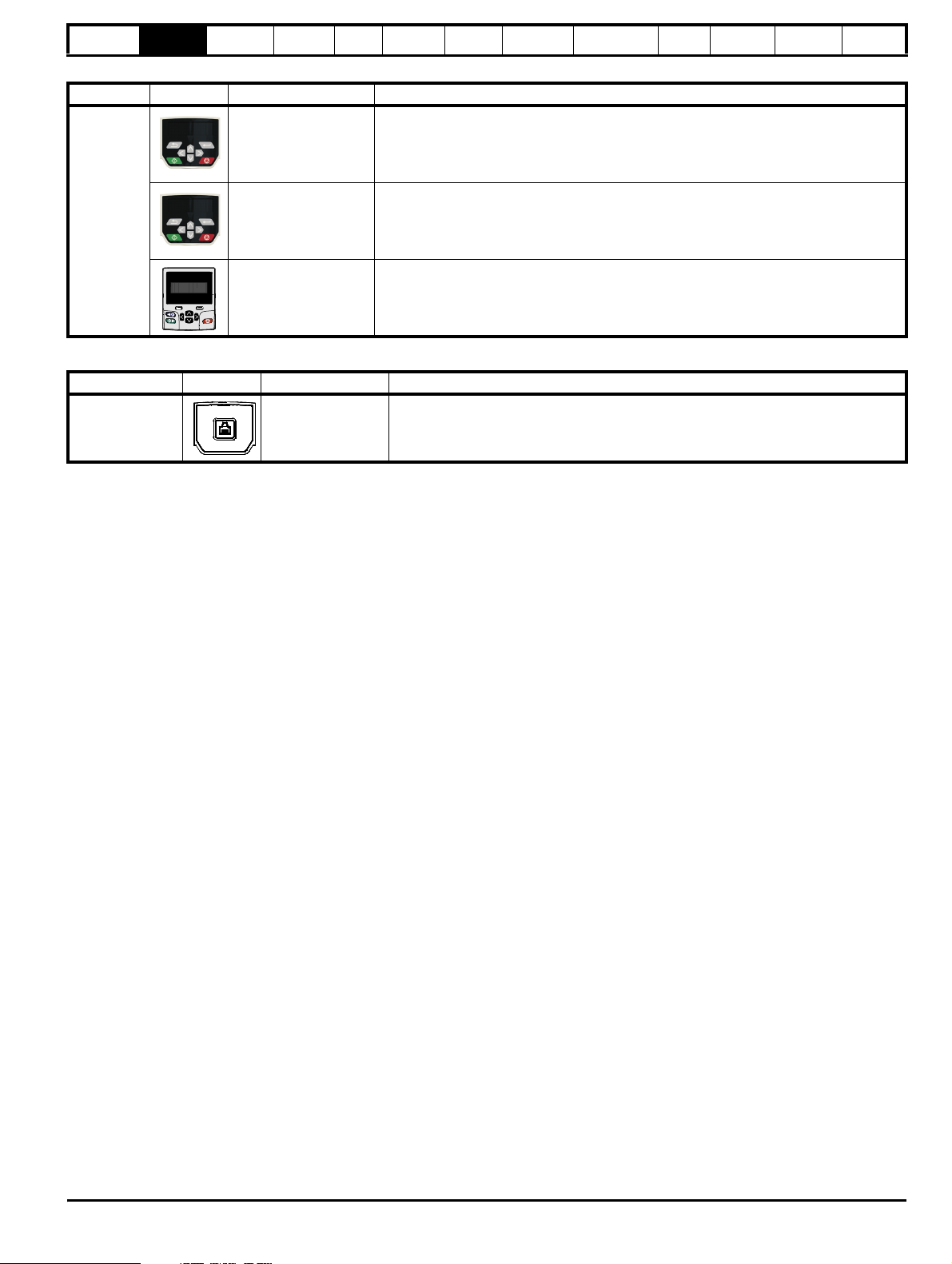
Table 2-3 Keypad identification
Type Keypad Name Further Details
Onboard
PLC
Advanced
parameters
Diagnostics
UL
information
Remote LCD keypad option
Remote Keypad with a LCD display
LCD keypad option
Keypad with a LCD display
Remote LCD keypad option
Remote Keypad with a LCD display and real time clock
Keypad
Remote-Keypad
CI-Keypad
Remote-Keypad RTC
Table 2-4 Compact Interface (CI) option module identification
Type Option Name Further Details
Communications CI-485 Adaptor
EIA 485 serial communications option
Provides a EIA 485 serial communications interface via an RJ45 connector.
Unidrive M400 Control User Guide 17
Issue Number: 1
Page 18
Safety
CAUTION
1
2
3
NOTE
1
2
information
Product
information
Mechanical
installation
Electrical
installation
Getting
started
Basic
parameters
Running
the motor
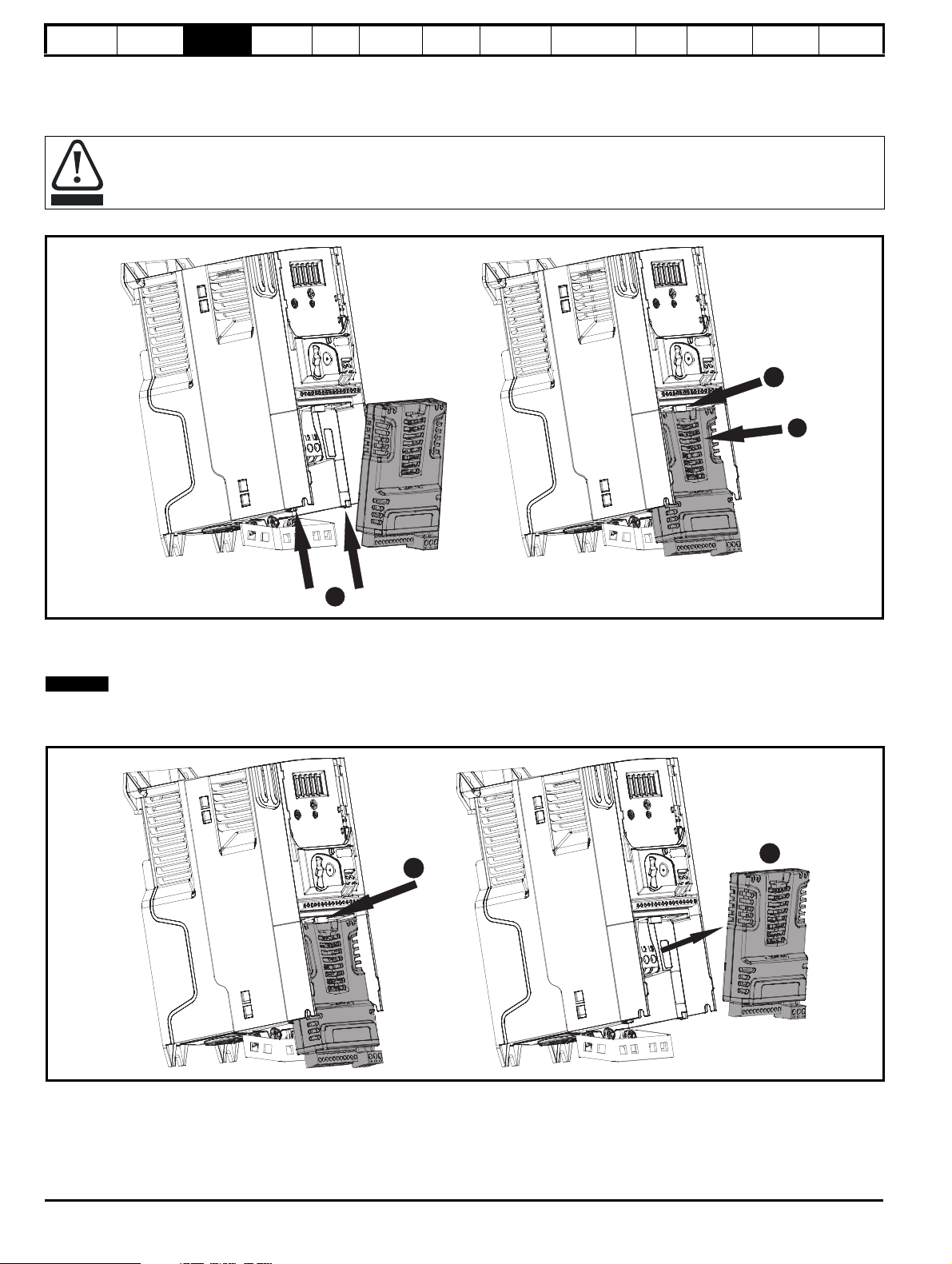
3 Mechanical installation
3.1 Installing / removing options and keypad
Power down the drive before installing / removing the SI option module. Failure to do so may result in damage to the product.
Figure 3-1 Installation of an SI option module (size 2 to 4)
Optimization
NV Media Card
Operation
Onboard
PLC
Advanced
parameters
Diagnostics
UL
information
• With the option module tilted slightly backwards, align and locate the two holes in the rear of the option module onto the two tabs (1) on the drive.
• Press the option module onto the drive as shown in (2) until the connector mates with the drive, ensuring that the tab (3) retains the option module
in place.
Check that the option module is securely located on the drive. Always ensure that the terminal cover is always replaced before use as this ensures
that the option module is firmly secured.
Figure 3-2 Removal of an SI option module (size 2 to 4)
• Press down on the tab (1) to release the option module from the drive housing as shown.
• Tilt the option module slightly towards you and pull away from the drive housing (2).
18 Unidrive M400 Control User Guide
Issue Number: 1
Page 19
Safety
1
A
2
1
3
information
Product
information
Mechanical
installation
Electrical
installation
Getting
started
Basic
parameters
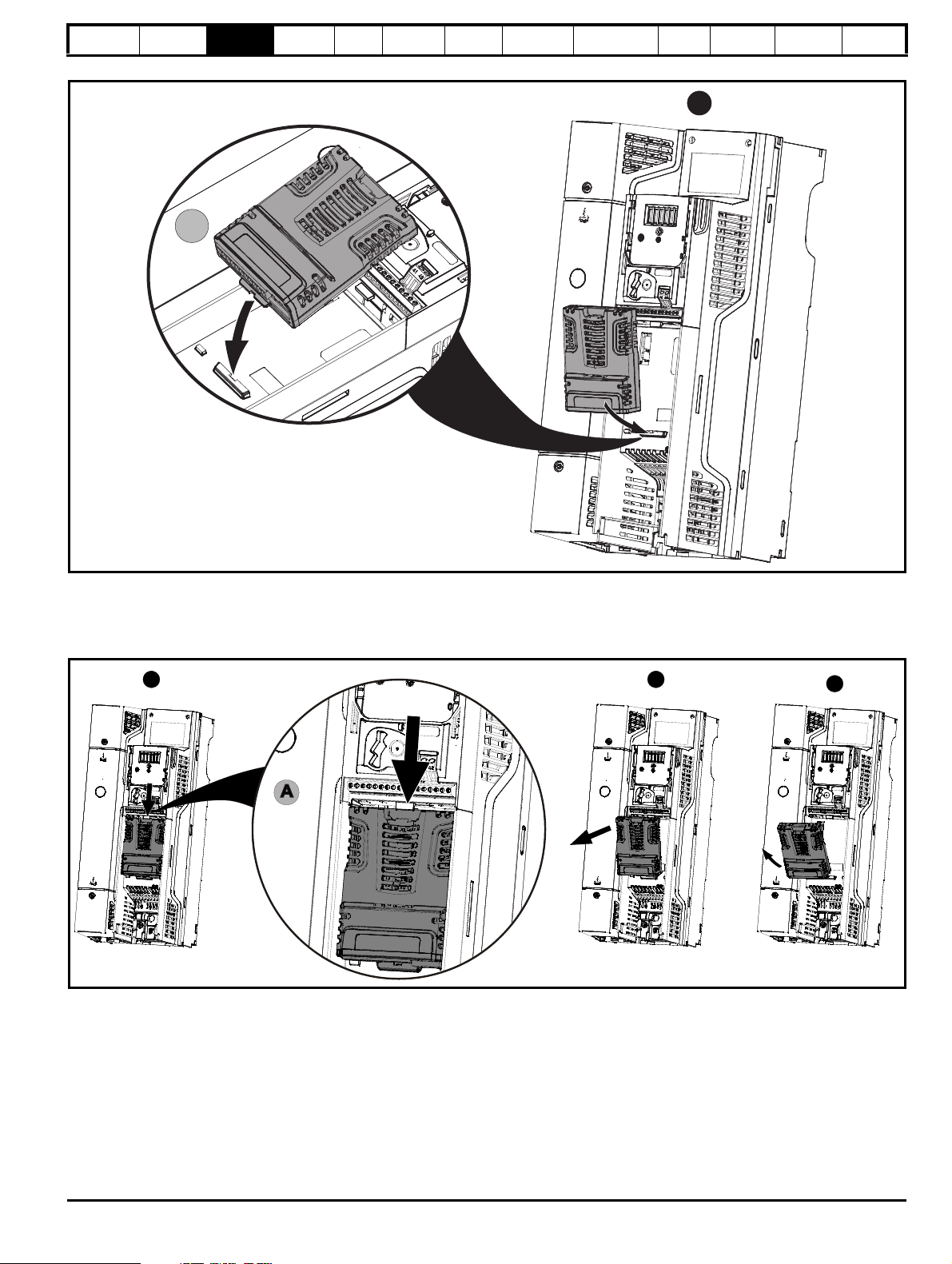
Figure 3-3 Installation of an SI option module (size 5 to 9)
Running
the motor
Optimization
NV Media Card
Operation
Onboard
PLC
Advanced
parameters
Diagnostics
UL
information
• Move the option module in the direction shown (1).
• Align and insert the option module tab into the slot provided. This is shown in the detailed view (A).
• Press down on the option module until it locks into place.
Figure 3-4 Removal of an SI option module (size 5 to 9)
• To release the option module from the drive housing, press down on the tab (1) as shown in detailed view (A).
• Tilt the option module towards you as shown in (2).
• Remove the option module by lifting away from the drive as shown in (3).
Unidrive M400 Control User Guide 19
Issue Number: 1
Page 20
Safety
1
2
3
1
information
Product
information
Mechanical
installation
Electrical
installation
Getting
started
Basic
parameters
Running
the motor
Optimization
NV Media Card
Operation
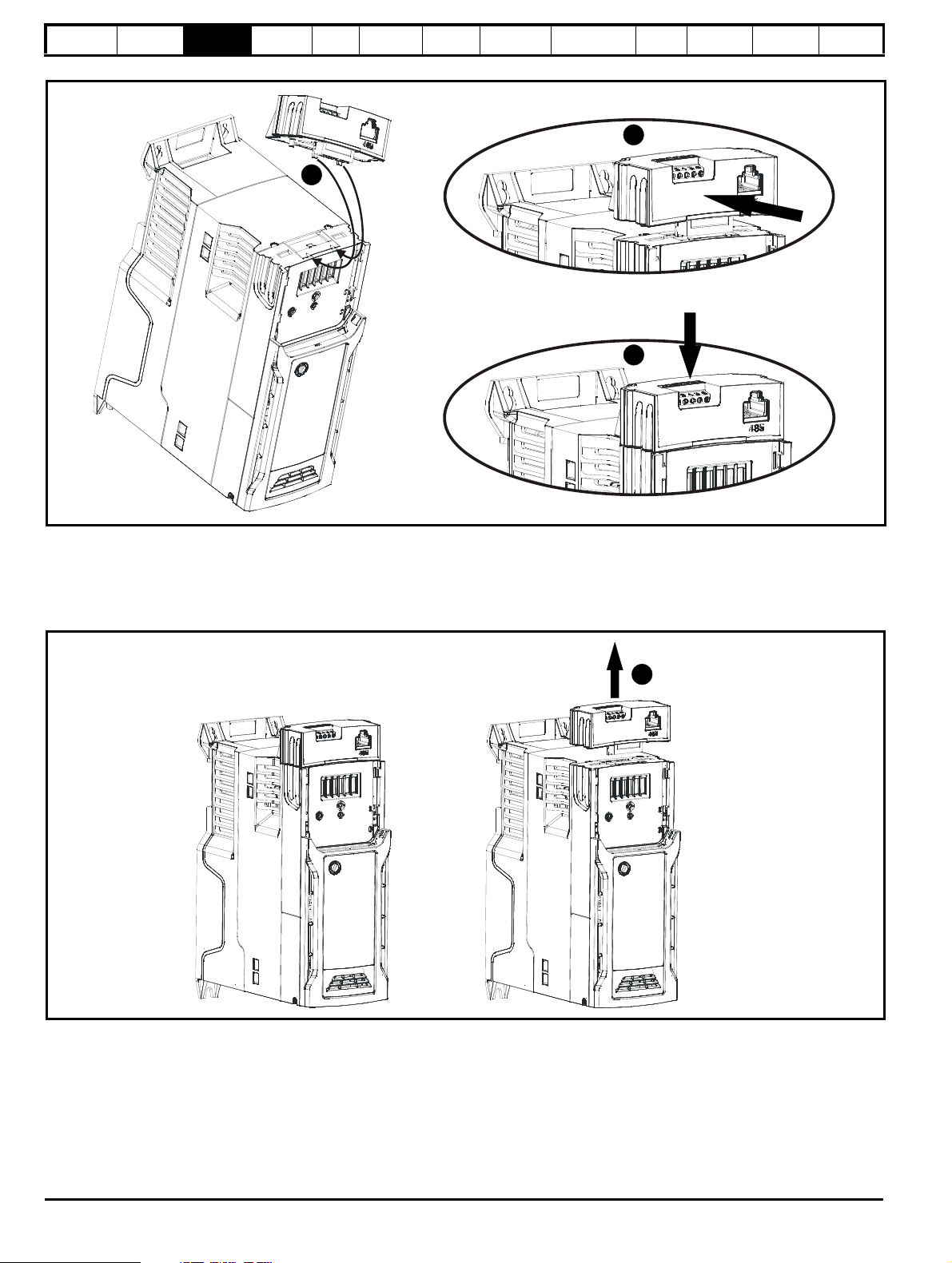
Figure 3-5 Installing the AI-485 / AI-Backup Adaptor to the drive (AI-485 Adaptor shown)
Onboard
PLC
Advanced
parameters
Diagnostics
UL
information
1. Identify the two plastic fingers on the underside of the AI-485 / AI-Backup Adaptor (1) - then insert the two fingers into the corresponding slots in
the spring loaded sliding cover on the top of the drive.
2. Hold the adaptor firmly and push the spring loaded protective cover towards the back of the drive to expose the connector block (2) below.
3. Press the adaptor downwards (3) until the adaptor connector locates into the drive connection below.
Figure 3-6 Removal of the AI-485 / AI-Backup adaptor (AI-485 Adaptor shown)
* To remove the AI-485 / AI-Backup Adaptor, pull it up and away from the drive in the direction shown (1)
20 Unidrive M400 Control User Guide
Issue Number: 1
Page 21
Safety
NOTE
NOTE
information
Product
information
Mechanical
installation
Electrical
installation
Getting
started
Basic
parameters
Running
the motor
Optimization
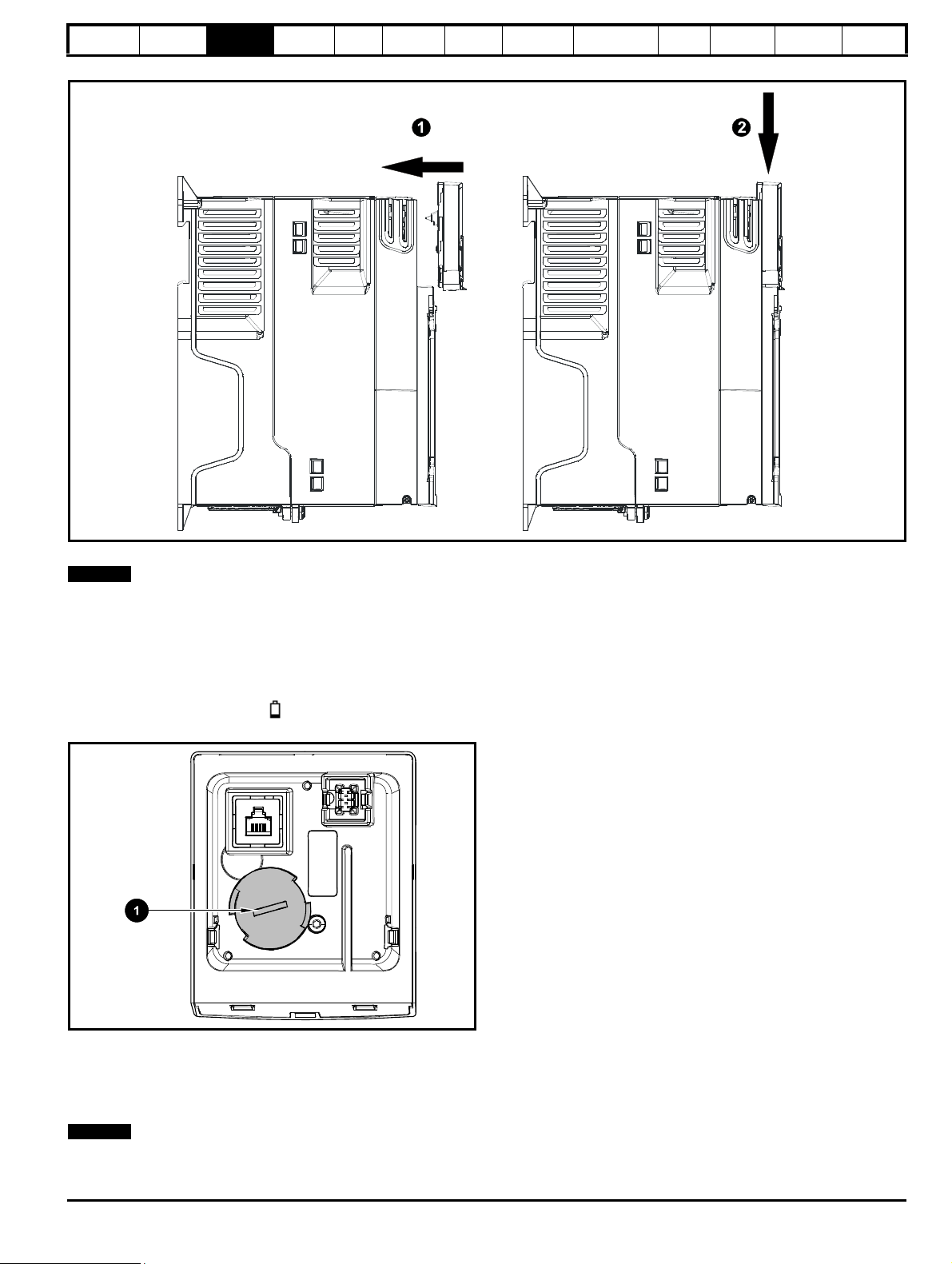
Figure 3-7 Installing the CI-Keypad / CI-485 Adaptor on the drive (CI-Keypad shown)
NV Media Card
Operation
Onboard
PLC
Advanced
parameters
Diagnostics
UL
information
To remove the CI-Keypad / CI-485 Adaptor, reverse the installation procedure shown in Figure 3-7.
The CI-Keypad / CI-485 Adaptor can be installed / removed while the drive is powered up and running motor, providing that the drive is not operating
in keypad mode.
3.2 Real time clock battery replacement
Those keypads which have the real time clock feature contain a battery to ensure the clock works when the drive is powered down. The battery has a
long life time but if the battery needs to be replaced or removed, follow the instructions below.
Low battery voltage is indicated by
Figure 3-8 Remote Keypad RTC (rear view)
low battery symbol on the keypad display.
Figure 3-8 above illustrates the rear view of the Remote Keypad RTC.
1. To remove the battery cover insert a flat head screwdriver into the slot as shown (1), push and turn anti-clockwise until the battery cover is
released.
2. Replace the battery (the battery type is: CR2032).
3. Reverse point 1 above to replace battery cover.
Ensure the battery is disposed of correctly.
Unidrive M400 Control User Guide 21
Issue Number: 1
Page 22

Safety
123456
8
1
NOTE
NOTE
information
Product
information
Mechanical
installation
Electrical
installation
Getting
started
Basic
parameters
Running
the motor
Optimization
NV Media Card
Operation
Onboard
PLC
Advanced
parameters
Diagnostics
UL
information
4 Electrical installation
4.1 24 Vdc supply
The 24 Vdc supply connected to the +24 V supply terminals on the AIBackup adaptor provides the following functions:
• It can be used as a back-up power supply to keep the control circuits
of the drive powered up when the line power supply is removed. This
allows any fieldbus modules or serial communications to continue to
operate. If the line power supply is re-applied, then the normal
operation can carry on after the drive automatically re-initializes the
power board parameters.
• It can be used to clone or load parameters and user programs in
order to pre-configure drives when the line power supply is not
available. The keypad can be used to setup parameters if required.
However, the drive will be in the Under Voltage state unless the line
power supply is enabled, therefore diagnostics may not be possible.
(Power down save parameters are not saved when using the 24 V
back-up power supply input).
The working voltage range of the 24 V back-up power supply is as
follows:
0 V (connected internally to 0V common - Control
0 V
Terminal 1)
+ 24 V + 24 V Backup supply input
Nominal operating voltage 24.0 Vdc
Minimum continuous operating voltage 19.2 V
Maximum continuous operating voltage 30.0 V
Minimum start up voltage 12.0 V
Minimum power supply requirement at 24 V 20 W
Recommended fuse 1 A, 50 Vdc
Minimum and maximum voltage values include ripple and noise. Ripple
and noise values must not exceed 5 %.
Figure 4-1 Location of the 24 Vdc power supply connection on the
AI-Backup adaptor
4.2 Communication connections
Installing an AI-485 adaptor provides the drive with a 2 wire EIA 485
serial communications interface. This enables the drive set-up, operation
and monitoring to be carried out with a PC or controller as required.
Figure 4-2 Location of the AI-485 adaptor option
4.2.1 EIA 485 serial communications
The drive only supports Modbus RTU protocol. See Table 4-1 for the
connection details.
Standard Ethernet cables must not be used when connecting drives on
a EIA 485 network as they do not have the correct twisted pairs for the
pinout of the serial comms port.
Table 4-1 Serial communication port pin-outs (RJ45)
Minimum number of connections are 2, 3, 7 and shield.
Table 4-2 Serial communication port pin-outs (screw terminal block)
Pin Function
1 120 Ω Termination resistor
2RX TX
30 V
4 +24 V (100 mA) output
5 Not connected
6 TX enable
7RX\ TX\
8 RX\ TX\ (if termination resistors are required, link to pin 1)
Pin Function
10 V
2 RX\ TX\ (if termination resistor required, link to pin 4)
3RX TX
4 120 Ω Termination resistor
5 TX Enable
6 +24 V (100 mA) output
The connections on the RJ45 connector and terminal block are in
parallel.
22 Unidrive M400 Control User Guide
Issue Number: 1
Page 23
Safety
WARNING
NOTE
WARNING
WARNING
CAUTION
WARNING
NOTE
NOTE
information
Product
information
Mechanical
installation
Electrical
installation
Getting
started
Basic
parameters
Running
the motor
Optimization
NV Media Card
Operation
Onboard
PLC
Advanced
parameters
Diagnostics
UL
information
4.2.2 Isolation of the EIA 485 serial communication
port
The serial communication port is single insulated and meets the
requirements for ELV.
When using the communications port with a personal
computer or centralised controller e.g. PLC, an isolation
device must be included with a rated voltage at least equal
to the drive supply voltage. Ensure that the correct fuses are
installed at the drive input, and that the drive is connected to
the correct supply voltage.
If a serial communications converter other than the CT
Comms cable is used to connect to other circuits classified
as Safety Extra Low Voltage (SELV) (e.g. to a personal
computer), then a safety isolating barrier must be included to
maintain the SELV classification.
An isolated serial communications lead has been designed to connect
the drive to IT equipment (such as laptop computers), and is available
from the supplier of the drive. See below for details:
Table 4-3 Isolated serial comms lead details
Part number Description
4500-0096 CT USB Comms cable
The “isolated serial communications” lead has reinforced insulation as
defined in IEC60950 for altitudes up to 3,000 m.
4.3 Control connections
4.3.1 General
Table 4-4 The control connections consist of:
Function Qty
Single ended analog
input
Control parameters
Mode, offset, invert,
2
scaling, destination
available
Analog output 2 Source, mode, scaling 7, 8
Digital input 6
Destination, invert, logic
select
Input / output mode select,
Digital input / output 2
destination / source, invert,
logic select
Digital output 2 Source, mode 7, 8
Frequency input 1
Maximum reference, input
limit, scaling, destination
Rotary lines per revolution,
filter, frequency feedback,
maximum frequency
AB Encoder input 1
feedback, position scaling,
position counter reset,
input limit, frequency
reference scaling
PWM or Frequency
output
Motor thermistor
input
Source scaling, maximum
1
output frequency, mode
Mode, type, trip threshold,
1
reset threshold
Relay 1 Source, invert 41, 42
Drive enable (Safe
Torque Off)
2
+ 10 V User output 1 4
+ 24 V User output 2 9, 17
0V common 2 1, 6
0V Safe Torque Off 2
Ter minal
number
2, 3, 5
5, 12, 13, 14,
15, 16
10, 11
15
15, 16
10
14
31, 34
(frame 1- 4)
31, 35
(frame 5 - 9)
32, 33
(frame 1- 4)
32, 36
(frame 5 - 9)
The 0V terminals on the Safe Torque Off are isolated from each other
and the 0V common (size 1 to 4), the 0V terminals on the Safe Torque
Off function on size 5 to 9 are common with the user 0V terminals.
Key:
Destination parameter:
Source parameter:
Indicates the parameter which is being
controlled by the terminal / function
Indicates the parameter being output by the
terminal
Analog - indicates the mode of operation of
the terminal, i.e. voltage 0-10 V, current 4-20
Mode parameter:
mA etc.
Digital - indicates the mode of operation of the
terminal.
All analog terminal functions can be programmed in menu 7.
All digital terminal functions (including the relay) can be programmed in
menu 8.
The control circuits are isolated from the power circuits in the
drive by basic insulation (single insulation) only. The installer
must ensure that the external control circuits are insulated
from human contact by at least one layer of insulation
(supplementary insulation) rated for use at the AC supply
voltage.
If the control circuits are to be connected to other circuits
classified as Safety Extra Low Voltage (SELV) (e.g. to a
personal computer), an additional isolating barrier must be
included in order to maintain the SELV classification.
If any of the digital inputs (including the drive enable input)
are connected in parallel with an inductive load (i.e.
contactor or motor brake) then suitable suppression (i.e.
diode or varistor) should be used on the coil of the load. If no
suppression is used then over voltage spikes can cause
damage to the digital inputs and outputs on the drive.
Ensure the logic sense is correct for the control circuit to be
used. Incorrect logic sense could cause the motor to be
started unexpectedly. Positive logic is the default state for the
drive.
N
Any signal cables which are carried inside the motor cable (i.e. motor
thermistor, motor brake) will pick up large pulse currents via the cable
capacitance. The shield of these signal cables must be connected to
ground close to the point of exit of the motor cable, to avoid this noise
current spreading through the control system.
N
The Safe Torque Off drive enable terminals are positive logic input only
(see Figure 4-4 on page 24).
Unidrive M400 Control User Guide 23
Issue Number: 1
Page 24

Safety
Frequency
Torque (active current)
Analog
frequency
reference 1
Analog
frequency
reference 2
4
5
7
6
0V common
1
2
3
17
0V common
+10 V
41
42
Relay
(over-voltage
category II)
Drive OK
12
13
At zero frequency
Run forward
Jog forward
select
Run reverse
Analog input 1/
input 2 select
9
11
+24 V
+24 V
10
14
15
16
8
1
17
41
42
34
32
33
31
STO
Channel 1
STO
Channel 2
STO Input 1
0V
STO1
0VSTO2
STO Input 2
31
35
32
36
STO
Channel 1
STO
Channel 2
STO Input 1
0V
STO Input 2
0V
WARNING
information
Product
information
Mechanical
installation
Electrical
installation
Figure 4-3 Default terminal functions
Getting
started
Basic
parameters
Running
the motor
Optimization
NV Media Card
Operation
Onboard
PLC
4.3.2 Control terminal specification
1 0V common
Function
2 Analog input 1
Default function Frequency reference.
Type of input
Mode controlled by… Pr 07.007
Operating in voltage mode (default)
Full scale voltage range ±10 V ±3 %
Maximum offset ±30 mV
Absolute maximum voltage
range
Input resistance 100 k
Resolution 12 bits (11 bits plus sign)
Operating in current mode
Current ranges
Maximum offset 250 µA
Common mode input voltage
range
Resolution 11 bits
External fuse rating 80 mA
Common to all modes
Sample rate 4 ms
Advanced
parameters
Common connection for all external
devices.
Diagnostics
UL
information
Bipolar single-ended analog voltage or
unipolar differential current.
-18 V to +30 V relative to 0 V
0 to 20 mA ±5 %, 20 to 0 mA ±5 %,
4 to 20 mA ±5 %, 20 to 4 mA ±5%
0V to +12 V
To avoid damage to the drive, a fuse or other over-current
protection should be installed in the analog current input
circuit.
When connecting a two wire sensor which has a 24 V input and a mA
output, to the current input, the 24 V input can be connected to the +24 V
terminal (9), while the mA output can be connected to the analog input 1
terminal (2). The analog input 1 return terminal (3) needs to be
Figure 4-4 Safe Torque Off inputs (size 1 to 4)
connected to the 0V terminal (1).
3 Analog input 1 return
Function
Return terminal for shunt resistor (current
mode)
4 +10 V user output
Function Supply for external analog devices
Nominal voltage 10.2 V
Figure 4-5 Safe Torque Off inputs (size 5 to 9)
24 Unidrive M400 Control User Guide
Voltage tolerance ±3 %
Maximum output current 5 mA
Issue Number: 1
Page 25
Safety
information
Product
information
Mechanical
installation
Electrical
installation
Getting
started
Basic
parameters
Running
the motor
Optimization
NV Media Card
Operation
Onboard
PLC
Advanced
parameters
Diagnostics
UL
information
5 Analog input 2
Default function Frequency reference
Unipolar single-ended analog voltage,
Type of input
unipolar single-ended current or digital
input (positive or negative logic).
Mode controlled by.... Pr 07.011
Operating in voltage mode (default)
Full scale voltage range 0 V to +10 V ±3 %
Maximum offset ±30 mV
Absolute maximum voltage
range
-18 V to +30 V relative to 0 V
Input resistance 100 k
Resolution 11 bits
Sample rate 4 ms
Operating in current mode
Current ranges
0 to 20 mA ±4 %, 20 to 0 mA ±4 %,
4 to 20 mA ±4 %, 20 to 4 mA ±4 %
Maximum offset 250 µA
Absolute maximum voltage
range
-18 V to +30 V relative to 0 V
Resolution 11 bits
Sample rate 4 ms
Operating in digital mode
Logic mode controlled by… Pr 08.010
Absolute maximum voltage
range
-18 V to +30 V relative to 0 V
Impedance 6.8 k
Input threshold 10 V ±0.8 V (IEC 61131-2)
Sample rate
1 ms when routed to destinations
Pr 06.035 or Pr 06.036, otherwise 4 ms.
6 0V common
Function Common connection for all external devices
7 Analog output 1
8 Analog output 2
Terminal 7 default function Frequency output
Terminal 8 default function Motor active current
Unipolar single-ended analog voltage,
Type of output
unipolar single-ended current or digital
output.
Mode controlled by… Pr 07.021, Pr 07.024
Operating in voltage mode (default)
Voltage range 0 to +10 V ±5 %
Maximum offset 15 mV
Minimum load resistance 500
Protection Short circuit relative to 0 V
Operating in current mode
Current ranges
0 to 20 mA ±4 %,
4 to 20 mA ±4 %
Maximum load resistance 500
Operating in digital output mode
Nominal maximum output current 50 mA
Voltage range 0 V to +24 V
Common to all modes
Resolution 0.1 %
Sample rate 4 ms
10 Digital I/O 1
11 Digital I/O 2
Terminal 10 default function AT ZERO FREQUENCY output
Terminal 11 default function None
Positive or negative logic digital inputs,
Type
positive logic voltage source outputs.
PWM or frequency output modes can be
selected on output 1.
Input / output mode controlled by
…
Pr 08.031, Pr 08.032
Operating as in input
Logic mode controlled by… Pr 08.010
Absolute maximum applied
voltage range
-8 V to +30 V relative to 0 V
Impedance 6.8 k
Input threshold 10 V ±0.8 V (IEC 61131-2)
Operating as an output
Nominal maximum output
current
50 mA
Maximum output current 200 mA (total including +24 Vout)
Common to all modes
Voltage range 0 V to +24 V
Sample rate
1 ms when routed to destinations
Pr 06.035 or Pr 06.036, otherwise 4 ms.
12 Digital Input 3
13 Digital Input 4
Terminal 12 default function RUN FORWARD input
Terminal 13 default function RUN REVERSE input
Type Negative or positive logic digital inputs
Logic mode controlled by… Pr 08.010
Voltage range 0 V to +24 V
Absolute maximum applied
voltage range
-18 V to +30 V relative to 0 V
Impedance 6.8 k
Input threshold 10 V ±0.8 V (IEC 61131-2)
Sample rate
1 ms when routed to destinations
Pr 06.035 or Pr 06.036, otherwise 4 ms.
14 Digital Input 5
Terminal 14 default function Analog INPUT 1 / INPUT 2 select
Negative or positive logic digital input or
Type
motor thermistor input (bias for
DIN44081 ptc, KTY84, PT1000, PT2000
and other types) mode can be selected.
Input mode controlled by… Pr 08.035
Operating as digital input
Logic mode controlled by… Pr 08.010
Voltage range 0 V to +24 V
Absolute maximum applied
voltage range
-18 V to +30 V relative to 0 V
Impedance 6.8 k
Input threshold 10 V ±0.8 V (IEC 61131-2)
Sample rate
1 ms when routed to destinations
Pr 06.035 or Pr 06.036, otherwise 4 ms.
9 +24 V user output
Function Supply for external digital devices
Voltage tolerance ±20 %
Maximum output current
200 mA (total including all Digital Outputs)
Protection Current limit and trip
Unidrive M400 Control User Guide 25
Issue Number: 1
Page 26

Safety
NOTE
WARNING
information
Product
information
Mechanical
installation
Electrical
installation
Getting
started
Basic
parameters
Running
the motor
15 Digital Input 6
16 Digital Input 7
Terminal 15 default function JOG SELECT input
Terminal 16 default function None
Negative or positive logic digital inputs,
Type
frequency input (digital input 6) or AB
encoder input (digital input 6 and 7).
Input mode controlled by... Pr 08.036
Operating as digital input
Logic mode controlled by… Pr 08.010
Operating as frequency or AB encoder input
Maximum input frequency 100 kHz
Common to all modes
Voltage range 0 V to +24 V
Absolute maximum applied
-18 V to +30 V relative to 0 V
voltage range
Impedance 6.8 k
Input threshold 10 V ±0.8 V (IEC 61131-2)
Sample rate
1 ms when routed to destinations
Pr 06.035 or Pr 06.036, otherwise 4 ms.
N
To use an encoder on the AB encoder input with 5 V encoder signals, a
5 V to 24 V level converter e.g. Motrona PU210, will be required.
17 +24 V user output
Function Supply for external digital devices.
Voltage tolerance ±20 %
Maximum output current 200 mA (total including all Digital
Protection Current limit trip.
31
Safe Torque Off function (drive enable)
(frame size 1 to 4)
34
Type Positive logic only digital input
Voltage range 0 to +24 V
Absolute maximum applied
voltage
Logic Threshold 10 V ±5 V
Low state maximum voltage for
disable to SIL3 and PL e
Impedance
Low state maximum current for
disable to SIL3 and PL e
Response time
The Safe Torque Off function may be used in a safety-related application in
preventing the drive from generating torque in the motor to a high level of
integrity. The system designer is responsible for ensuring that the complete
system is safe and designed correctly according to the relevant safety
standards. If the Safe Torque Off function is not required, these terminals
are used for enabling the drive.
32 0V STO2 (frame size 1 to 4)
Function Common connection for STO2
33 0V STO1 (frame size 1 to 4)
Function Common connection for STO1
Outputs)
30 V
5 V
>4 mA @ 15 V, <15 mA @30 V (IEC
61131-2, type 1)
0.5 mA
Nominal: 12 ms
Maximum: 20 ms
Optimization
31
35
NV Media Card
Operation
Safe Torque Off function (drive enable)
(frame size 5 to 9)
Onboard
PLC
Advanced
parameters
Diagnostics
UL
information
Type Positive logic only digital input
Voltage range 0 to +24 V
Absolute maximum applied
voltage
30 V
Logic Threshold 10 V ±5 V
Low state maximum voltage for
disable to SIL3 and PL e
Impedance
Low state maximum current for
disable to SIL3 and PL e
Response time
5 V
>4 mA @ 15 V (IEC 61131-2, type 1, 3.3
k)
0.5 mA
Nominal: 6 ms
Maximum: 20 ms
The Safe Torque Off function may be used in a safety-related application in
preventing the drive from generating torque in the motor to a high level of
integrity. The system designer is responsible for ensuring that the complete
system is safe and designed correctly according to the relevant safety
standards. If the Safe Torque Off function is not required, these terminals
are used for enabling the drive.
41
Relay contacts
42
Default function Drive OK indicator
Contact voltage rating
Contact maximum current rating
Contact minimum recommended
rating
240 Vac, Installation over-voltage
category II
2 A AC 240 V
4 A DC 30 V resistive load
12 V 100 mA
Contact type Normally open
Default contact condition
Closed when power applied and drive
OK
Update rate 1 ms
To prevent the risk of a fire hazard in the event of a fault, a
fuse or other over-current protection must be installed in the
relay circuit.
4.3.3 Accuracy and resolution
Frequency:
The absolute frequency accuracy depends on the accuracy of the
oscillator used with the drive microprocessor. The accuracy of the
oscillator is ± 0.02 % , and so the absolute frequency accuracy is
± 0.02 % of the reference, when a preset frequency is used. If an analog
input is used, the absolute accuracy is further limited by the absolute
accuracy of the analog input.
The following data applies to the drive only; it does not include the
performance of the source of the control signals.
Open & closed loop resolution:
Preset frequency reference: 0.01 Hz
Analog input 1: 11 bit plus sign
Analog input 2: 11 bit
26 Unidrive M400 Control User Guide
Issue Number: 1
Page 27
Safety
NOTE
information
Product
information
Mechanical
installation
Electrical
installation
Getting
started
Basic
parameters
Running
the motor
Current:
The resolution of the current feedback is 10 bit plus sign.
Accuracy: typical 2 %
worst case 5 %
4.4 Safe Torque Off (STO)
The Safe Torque Off function provides a means for preventing the drive
from generating torque in the motor, with a very high level of integrity. It
is suitable for incorporation into a safety system for a machine. It is also
suitable for use as a conventional drive enable input.
The safety function is active when the STO input is in the logic-low state
as specified in the control terminal specification. The function is defined
according to EN 61800-5-2 and IEC 61800-5-2 as follows. (In these
standards a drive offering safety-related functions is referred to as a
PDS(SR)):
'Power that can cause rotation (or motion in the case of a linear motor) is
not applied to the motor. The PDS(SR) will not provide energy to the
motor which can generate torque (or force in the case of a linear motor)'
This safety function corresponds to an uncontrolled stop in accordance
with stop category 0 of IEC 60204-1.
The Safe Torque Off function makes use of the special property of an
inverter drive with an induction motor, which is that torque cannot be
generated without the continuous correct active behaviour of the inverter
circuit. All credible faults in the inverter power circuit cause a loss of
torque generation.
The Safe Torque Off function is fail-safe, so when the Safe Torque Off
input is disconnected the drive will not operate the motor, even if a
combination of components within the drive has failed. Most component
failures are revealed by the drive failing to operate. Safe Torque Off is
also independent of the drive firmware. This meets the requirements of
the following standards, for the prevention of operation of the motor.
Machinery Applications
The Safe Torque Off function has been independently assessed by
Notified Body, TüV Rheinland for use as a safety component of a
machine:
Prevention of unintended motor operation: The safety function "Safe
Torque Off" can be used in applications up to Cat 4. PL e according to
EN ISO 13849-1, SIL 3 according to EN 61800-5-2/ EN 62061/ IEC
61508, and in lift applications according to EN 81-1 and EN81-2.
Type examination
certificate number
01/205/5387.01/15 2015-01-29 M400 5 to 9
01/205/5383.02/15 2015-04-21 M400 1 to 4
This certificate is available for download from the TüV Rheinland website
at: http://www.tuv.com.
Safety Parameters as verified by TüV Rheinland:
According to IEC 61508-1 to 07 / EN 61800-5-2 / EN 62061
Typ e Va lue
Proof test interval 20 years All
High demand or a continuous mode of operation
PFH (1/h)
PFH (1/h)
Low demand mode of operation (not EN 61800-5-2)
PFDavg
PFDavg
Date of issue Model Frame sizes
9.61 x 10
4.16 x 10
8.4 x 10
3.64 x 10
Percentage of SIL
-11
1/h
-11
1/h
-6
-6
3 allowance
<1 % 1 to 4
<1 % 5 to 9
< 1 % 1 to 4
< 1 % 5 to 9
Frame
sizes
Optimization
NV Media Card
Operation
Onboard
PLC
Advanced
parameters
Diagnostics
UL
information
According to EN ISO 13849-1
Type Value Classification
Category 4
Performance Level (PL) e
(ST01)
MTTF
MTTF
MTTF
STO)
DC
avg
D
(ST02)
D
(Single channel
D
>2500 years High
>2500 years High
>2500 years High
99 % High
Mission time 20 years
Logic levels comply with IEC 61131-2:2007 for type 1 digital inputs rated
at 24 V. Maximum level for logic low to achieve SIL3 and PL e 5 V and
0.5 mA.
Lift (Elevator) Applications
The Safe Torque Off function has been independently assessed for use
as a safety component in lift (elevator) applications by Notified Body,
TüV Nord:
The Unidrive M drives series with Safe Torque Off (STO) function if
applied according to the "Conditions of application" fulfil the safety
requirements of the standards EN81-1, EN81-2, EN 81-50 and
EN60664-1and are in conformity with all relevant requirements of the
Directive 95/16/EC.
Certificate of Conformity
number
Date of issue Models
44799 13196202 04-08-2015 M400
The Safe Torque Off function can be used to eliminate electromechanical contactors, including special safety contactors, which would
otherwise be required for safety applications.
For further information contact the supplier of the drive.
UL Approval
The Safe Torque Off function has been independently assessed by
Underwriters Laboratories (UL). The on-line certification (yellow card)
reference is: FSPC.E171230.
Safety Parameters as verified by UL:
According to IEC 61508-1 to 7
Typ e Value
Safety Rating SIL 3
SFF > 99 %
-10
PFH (1/h)
4.43 x 10
(<1 % of SIL 3 allowance)
1/h
HFT 1
Beta Factor 2 %
CFF Not applicable
According to EN ISO 13849-1
Typ e Value
Category 4
Performance Level (PL) e
MTTF
D
2574 years
Diagnostic coverage High
CCF 65
Unidrive M400 Control User Guide 27
Issue Number: 1
Page 28
Safety
WARNING
WARNING
WARNING
WARNING
information
Product
information
Mechanical
installation
Electrical
installation
Getting
started
Basic
parameters
Running
the motor
Two-channel Safe Torque Off
The M400 models have dual channel STO.
The dual channel STO has two fully independent channels.
Each input meets the requirements of the standards as defined above.
If either or both inputs are set at a logic low state, there are no single
faults in the drive which can permit the motor to be driven.
It is not necessary to use both channels to meet the requirements of the
standards. The purpose of the two channels is to allow connection to
machine safety systems where two channels are required, and to
facilitate protection against wiring faults.
For example, if each channel is connected to a safety-related digital
output of a safety related controller, computer or PLC, then on detection
of a fault in one output the drive can still be disabled safely through the
other output.
Under these conditions, there are no single wiring faults which can
cause a loss of the safety function, i.e. inadvertent enabling of the drive.
In the event that the two-channel operation is not required, the two
inputs can be connected together to form a single Safe Torque Off input.
In this case it is important to note that a single short-circuit from the Safe
Torque Off input to a DC supply > 5 V could cause the drive to be
enabled.
This might occur through a fault in the wiring. This can be excluded
according to EN ISO 13849-2 by the use of protected wiring. The wiring
can be protected by either of the following methods:
• By placing the wiring in a segregated cable duct or other enclosure.
Or
• By providing the wiring with a grounded shield in a positive-logic
grounded control circuit. The shield is provided to avoid a hazard
from an electrical fault. It may be grounded by any convenient
method; no special EMC precautions are required.
Optimization
NV Media Card
Operation
Onboard
PLC
Advanced
parameters
Diagnostics
UL
information
Safe Torque Off does not provide electrical isolation.
The supply to the drive must be disconnected by an approved
isolation device before gaining access to power connections.
It is essential to observe the maximum permitted voltage of
5 V for a safe low (disabled) state of Safe Torque Off. The
connections to the drive must be arranged so that voltage
drops in the 0 V wiring cannot exceed this value under any
loading condition. It is strongly recommended that the Safe
Torque Off circuits be provided with a dedicated 0V
conductors which should be connected to terminals 32 and
33 (sizes 1 to 4) and terminals 32 and 36 (sizes 5 to 9) at the
drive.
Safe Torque Off over-ride
The drive does not provide any facility to over-ride the Safe Torque Off
function, for example for maintenance purposes.
Note on response time of Safe Torque Off, and use with safety
controllers with self-testing outputs:
Safe Torque Off has been designed to have a response time of greater
than 1 ms so that it is compatible with safety controllers whose outputs
are subject to a dynamic test with a pulse width not exceeding 1 ms.
Note on the use of servo motors, other permanent-magnet motors,
reluctance motors and salient-pole induction motors:
When the drive is disabled through Safe Torque Off, a possible (although
highly unlikely) failure mode is for two power devices in the inverter
circuit to conduct incorrectly.
This fault cannot produce a steady rotating torque in any AC motor. It
produces no torque in a conventional induction motor with a cage rotor. If
the rotor has permanent magnets and/or saliency, then a transient
alignment torque may occur. The motor may briefly try to rotate by up to
180° electrical, for a permanent magnet motor, or 90° electrical, for a
salient pole induction motor or reluctance motor. This possible failure
mode must be allowed for in the machine design.
The design of safety-related control systems must only be
done by personnel with the required training and experience.
The Safe Torque Off function will only ensure the safety of a
machine if it is correctly incorporated into a complete safety
system. The system must be subject to a risk assessment to
confirm that the residual risk of an unsafe event is at an
acceptable level for the application.
Safe Torque Off inhibits the operation of the drive, this
includes inhibiting braking. If the drive is required to provide
both braking and Safe Torque Off in the same operation (e.g.
for emergency stop) then a safety timer relay or similar device
must be used to ensure that the drive is disabled a suitable
time after braking. The braking function in the drive is
provided by an electronic circuit which is not fail-safe. If
braking is a safety requirement, it must be supplemented by
an independent fail-safe braking mechanism.
28 Unidrive M400 Control User Guide
Issue Number: 1
Page 29
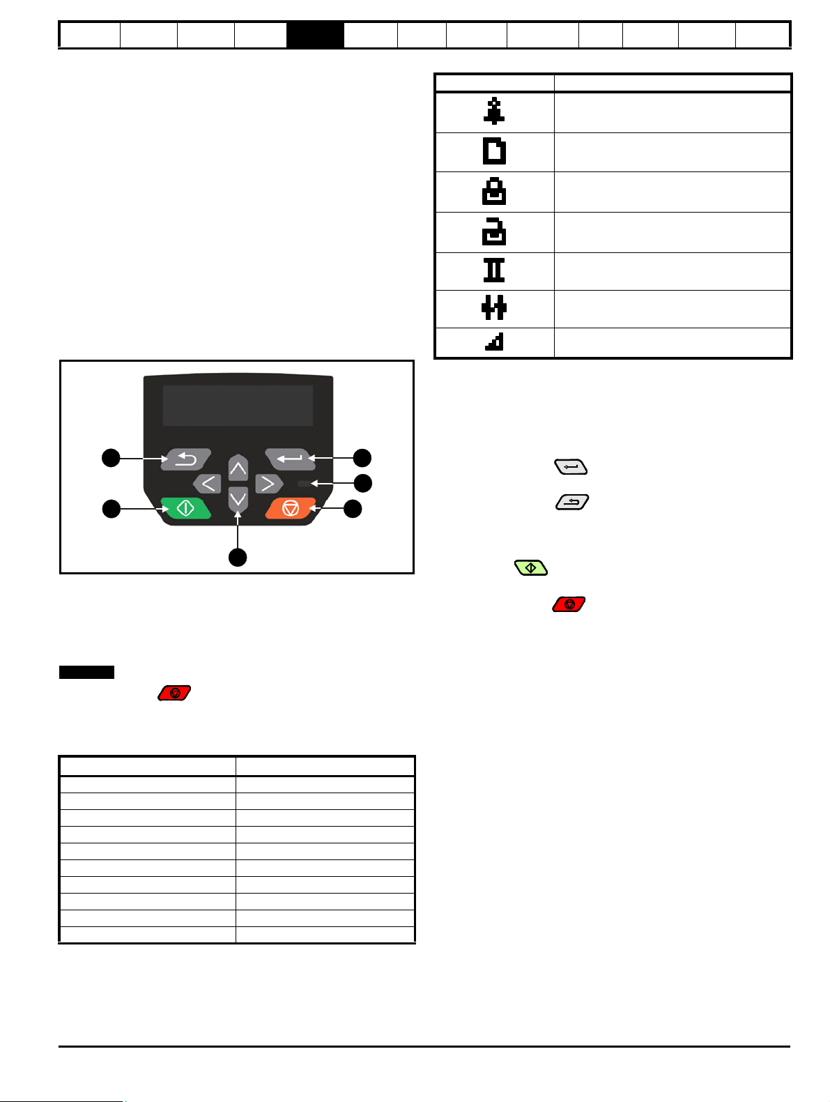
Safety
4
2
3
1
6
5
NOTE
information
Product
information
Mechanical
installation
Electrical
installation
Getting
started
Basic
parameters
the motor
5 Getting started
This chapter introduces the user interfaces, menu structure and security
levels of the drive.
5.1 Understanding the display
5.1.1 CI-Keypad
The keypad can only be mounted on the drive.
The CI-Keypad display consists of up to four rows of text. The upper two
rows show the drive status or the menu and parameter number currently
being viewed. When in status mode, an area one character wide and
four lines high on the right-hand side of the display, is reserved for
displaying actions that are active on the drive. The possible active
actions are given in Table 5-2.
The keypad powers up into the status state. The value of any two
parameters can be permanently displayed on the bottom two rows of the
screen in the status state. To do this enter the desired parameter
numbers into Pr 11.018 (Status Mode Parameter 1) and Pr 11.019
(Status Mode Parameter 2).
Figure 5-1 CI-Keypad
1. Escape button
2. Start button (Green)
3. Navigation keys (x4)
4. Stop / Reset button (red)
5. Status LED
6. Enter button
Running
Optimization
NV Media Card
Operation
Onboard
PLC
Advanced
parameters
Diagnostics
Table 5-2 Active action icon
Active action icon Description
Alarm active
NV media card being accessed
Drive security active
User security unlocked
Motor map 2 active
User program running
Keypad reference active
5.2 Keypad operation
5.2.1 Control buttons
The keypad consists of:
• Navigation keys - Used to navigate the parameter structure and
change parameter values.
• Enter / Mode button Used to change between parameter edit
and view mode, as well as entering data.
• Escape / Exit button Used to exit from parameter edit or view
mode. In parameter edit mode, if parameter values are edited and
the exit button pressed the parameter value will be restored to the
value it had on entry to edit mode.
• Start button Used to provide a 'Run' command if keypad
mode is selected.
• Stop / Reset button Used to reset the drive. In keypad mode
can be used for 'Stop'.
UL
information
The red stop button is also used to reset the drive.
The parameter value is correctly displayed on the keypad display as
shown in the below table.
Table 5-1 Keypad display formats
Display formats Value
IP Address 127. 0. 0. 0
MAC Address 01ABCDEF2345
Time 12:34:56
Date 31-12-13 or 12-31-13
Version number 01.02.00.00
Character ABCD
32 bit number with decimal point 21474836.47
16 bit binary number 0100001011100101
Text A1 A2
Number 10.00 Hz
Unidrive M400 Control User Guide 29
Issue Number: 1
Page 30
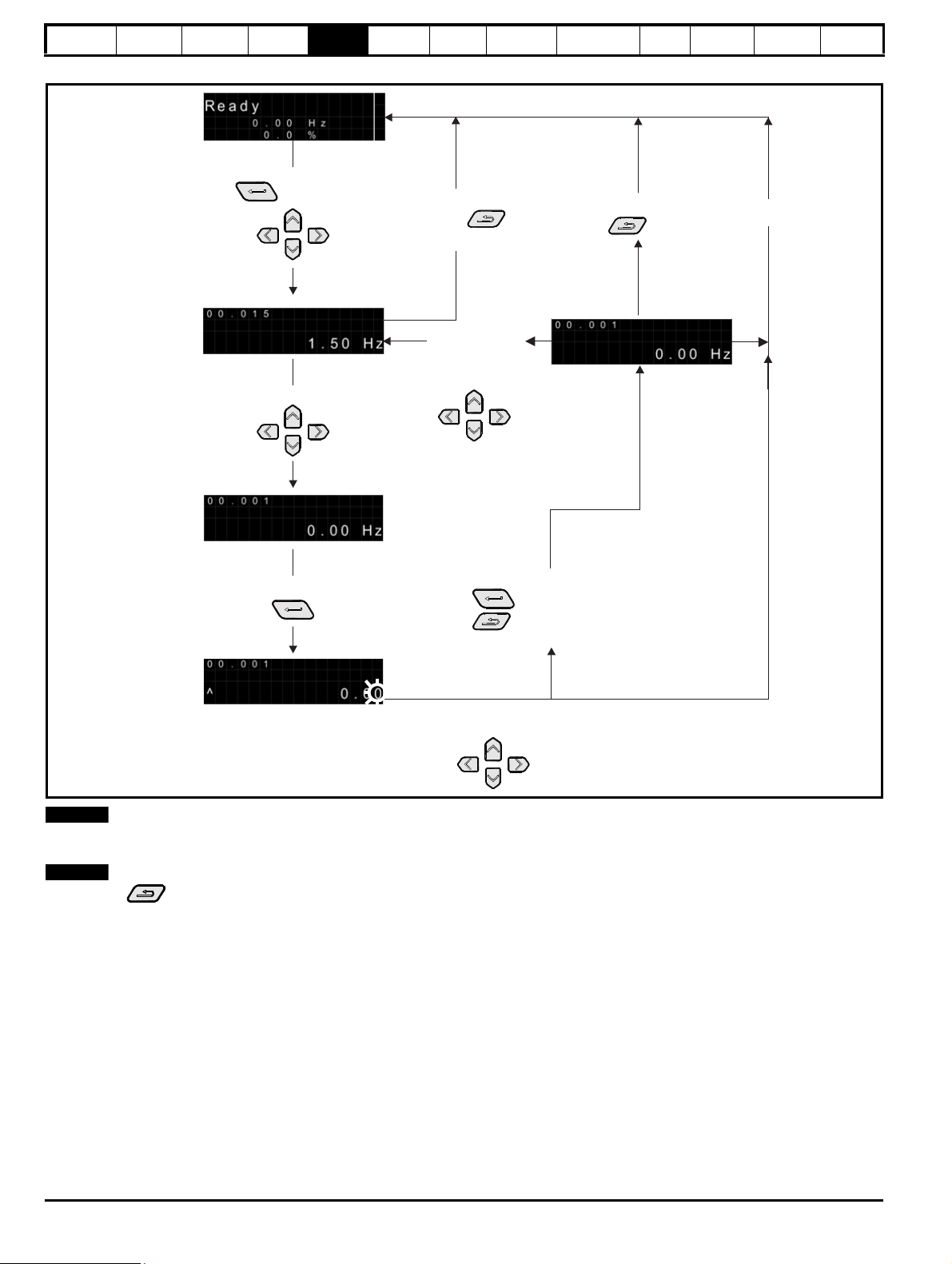
Safety
Status
Mode
buttons to
select another
parameter to
change if
required
Parameter
View Mode
When returning
to Parameter
View Mode
use the
To select parameter press
To enter Edit Mode,
Edit Mode
press
Change parameter values by pressing
(Character to be edited in
lower line of display flashing)
button
buttons
To enter Parameter View mode,
press
button or
Timeout
or press
button
button
Press
To return to status mode,
Press
Press
return the parameter to the pre-editied value
button to ignore new value
button to keep the new value
To return to Parameter View Mode,
Timeout
NOTE
NOTE
information
Product
information
Mechanical
installation
Figure 5-2 Display modes
Electrical
installation
Getting
started
Basic
parameters
Running
the motor
Optimization
NV Media Card
Operation
Onboard
PLC
Advanced
parameters
Diagnostics
UL
information
The navigation buttons can only be used to move between menus if Pr 00.010 has been set to show 'All Menus'. Refer to section 5.8 Parameter
access level and security on page 33.
If the Escape button is held down for 1 second, the display returns to status mode.
30 Unidrive M400 Control User Guide
Issue Number: 1
Page 31

Safety
2
1
Go to parameter :
0 . 0 0 . 0 0 0
1
Ready
0 . 00 Hz
0 . 0 %
34
Drive Overload
115 . 2 %
50 . 00 Hz
2
Trip
Over Volts
0 0 . 0 1 5
1 . 50 Hz
WARNING
NOTE
NOTE
0 1 . 0 1 1
0 0 . 0 0 0 0 1 . 0 1 0
0 1 . 0 0 9
0 2 . 0 0 0
**
information
Product
information
Mechanical
installation
Electrical
installation
Getting
started
Basic
parameters
5.2.2 Quick access mode
The quick access mode allows direct access to any parameter without
scrolling through menus and parameters.
To enter the quick access mode, press and hold the Enter
button on the keypad while in 'parameter view mode'.
Figure 5-3 Quick access mode
Running
the motor
Optimization
NV Media Card
Operation
Onboard
PLC
Advanced
parameters
Diagnostics
If the drive is ok and the parameters are not being edited or viewed, the
upper row of the display will show one of the following:
• Inhibit', 'Ready' or 'Run'.
3. Status mode: trip status
When the drive is in trip condition, the upper row of the display will
indicate that the drive has tripped and the lower row of the display will
show the trip code. For further information regarding trip codes, refer to
Table 12-2 Trip indications on page 139.
4. Status mode: Alarm status
During an 'alarm' condition the upper row of the display alternates
between the drive status (Inhibit, Ready or Run, depending on what is
displayed) and the alarm.
Do not change parameter values without careful
consideration; incorrect values may cause damage or a
safety hazard.
UL
information
5.2.3 Keypad shortcuts
In ‘parameter view mode’:
If the up and down keypad buttons are pressed together, then the
keypad display will jump to the start of the parameter menu being
viewed, e.g. Pr 05.005 being viewed, when the above buttons pressed
together will jump to Pr 05.000.
If the left and right keypad buttons are pressed together, then the
keypad display will jump to the last viewed parameter in Menu 0.
In 'parameter edit mode’:
If the up and down keypad buttons are pressed together, then the
parameter value of the parameter being edited will be set to 0.
If the left and right keypad buttons are pressed together, the least
significant digit (furthest right) will be selected on the keypad display for
editing.
Figure 5-4 Mode examples
When changing the values of parameters, make a note of the new
values in case they need to be entered again.
New parameter values must be saved to ensure that the new values
apply after the drive has been power cycled. Refer to section 5.6 Saving
parameters on page 33.
5.3 Menu structure
The drive parameter structure consists of menus and parameters.
The drive initially powers up so that only Menu 0 can be viewed. The up
and down arrow buttons are used to navigate between parameters and
once Pr 00.010 has been set to 'All Menus', the left and right buttons are
used to navigate between menus. For further information, refer to
section 5.8 Parameter access level and security on page 33.
Figure 5-5 Parameter navigation
1. Parameter view mode: Read write or Read only
2. Status mode: Drive OK status
Unidrive M400 Control User Guide 31
Issue Number: 1
* Can only be used to move between menus if all menus
have been enabled (Pr 00.010). Refer to section
5.8 Parameter access level and security on page 33.
The menus and parameters roll over in both directions. i.e. if the last
parameter is displayed, a further press will cause the display to rollover
and show the first parameter. When changing between menus the drive
remembers which parameter was last viewed in a particular menu and
thus displays that parameter.
5.3.1 CI-Keypad set-up menu
To enter the keypad set-up menu, press and hold the Escape
button on the keypad from status mode. All the keypad parameters are
saved to the keypad non-volatile memory when exiting from the keypad
set-up menu. To exit from the keypad set-up menu, press the
Escape or or button. Below are the keypad set-up
parameters.
Page 32

Safety
NOTE
NOTE
information
Product
information
Mechanical
installation
Electrical
installation
Getting
started
Basic
parameters
Running
the motor
Table 5-3 CI-Keypad set-up parameters
Parameters Range Type
English, French,
Keypad.00 Language
German, Italian,
Spanish and
RW
Chinese
Keypad.01 Show Units Off or On RW
Keypad.02 Backlight Level 0 to 100 % RW
Keypad.05 Show Raw Text Parameter Values Off or On RW
Keypad.06 Software Version
Keypad.07 Language version
00.00.00.00 to
99.99.99.99
00.00.00.00 to
99.99.99.99
RO
RO
Keypad.08 Font version 0 to 99 RO
The languages available will depend on the keypad software version.
* Keypad.08 will depend on the keypad software version.
It is not possible to access the keypad parameters via any
communications channel.
5.4 Advanced menus
The advanced menus consist of groups or parameters appropriate to a
specific function or feature of the drive. Menus 0 to 30 can be viewed on
the Keypad.
The option module menu (1.mm.ppp) is only displayed if the option
module is installed. Where 1 signifies the option module slot number and
the mm.ppp signifies the menu and parameter number of the option
module’s internal menus and parameters.
Table 5-4 Advanced menu descriptions
Menu Description
Commonly used basic set up parameters for quick / easy
0
programming
1 Frequency reference
2Ramps
3 Frequency control
4 Torque and current control
5 Motor control
6 Sequencer and clock
7 Analog I/O
8 Digital I/O
Programmable logic, motorized pot, binary sum, timers and
9
scope
10 Status and trips
11 Drive set-up and identification, serial communications
12 Threshold detectors and variable selectors
14 User PID controller
15 Option module slot 1 set-up menu
18 General option module application menu 1
20 General option module application menu 2
21 Second motor parameters
22 Menu 0 set-up
24 Option module slot 1 application menu
30 Onboard user programming application menu
Slot 1 Slot 1 option menus*
* Only displayed when the option module is installed.
Optimization
NV Media Card
Operation
Onboard
PLC
Advanced
parameters
Diagnostics
UL
information
5.4.1 Display messages
The following tables indicate the various possible mnemonics which can
be displayed by the drive and their meaning.
Table 5-5 Status indications
Upper row
string
Description
Drive
output
stage
The drive is inhibited and cannot be run.
The Safe Torque Off signals are not
applied to the Safe Torque Off terminals or
Inhibit
Pr 06.015 is set to 0. The other conditions
Disabled
that can prevent the drive from enabling
are shown as bits in Enable Conditions
(06.010).
The drive is ready to run. The drive enable
Ready
is active, but the drive inverter is not active
Disabled
because the final drive run is not active.
Stop
The drive is stopped / holding zero
frequency.
Enabled
Run The drive is active and running. Enabled
Supply Loss Supply loss condition has been detected Enabled
The motor is being decelerated to zero
Deceleration
frequency because the final drive run has
Enabled
been deactivated.
dc Injection The drive is applying dc injection braking. Enabled
The drive has tripped and no longer
Trip
controlling the motor. The trip code
Disabled
appears in the lower display.
Under
Vol tag e
The drive is in the under voltage state
either in low voltage or high voltage mode.
Disabled
Heat The motor pre-heat function is active Enabled
5.4.2 Alarm indications
An alarm is an indication given on the display by alternating the alarm
string with the drive status string on the display. Alarms strings are not
displayed when a parameter is being edited.
Table 5-6 Alarm indications
Alarm string Description
Brake resistor overload. Braking Resistor Thermal
Brake Resistor
Motor Overload
Drive overload
Auto Tune
Limit Switch
Option Slot 1 Option slot alarm.
Low AC Low voltage mode. See Low AC Alarm (10.107).
Current Limit
24V Backup
Lost
Accumulator (10.039) in the drive has reached
75.0 % of the value at which the drive will trip.
Motor Protection Accumulator (04.019) in the drive
has reached 75.0 % of the value at which the drive
will trip and the load on the drive is >100 %.
Drive over temperature. Percentage Of Drive
Thermal Trip Level (07.036) in the drive is greater
than 90 %.
The autotune procedure has been initialized and an
autotune in progress.
Limit switch active. Indicates that a limit switch is
active and that is causing the motor to be stopped.
Current limit active. See Current Limit Active
(10.009).
24V Backup not present. See 24V Alarm Loss
Enable (11.098)
32 Unidrive M400 Control User Guide
Issue Number: 1
Page 33

Safety
NOTE
information
Product
information
Mechanical
installation
Electrical
installation
Getting
started
Basic
parameters
Running
the motor
Optimization
NV Media Card
Operation
Onboard
PLC
Advanced
parameters
Diagnostics
UL
information
5.5 Changing the operating mode
Procedure
Use the following procedure only if a different operating mode is
required:
1. Ensure the drive is not enabled, i.e. drive is in Inhibit or Under
Voltage State.
2. Change the setting of Pr 00.079 as follows:
Pr 00.079 setting Operating mode
1 Open-loop
2RFC-A
The figures in the second column apply when serial communications are
used.
When the operating mode is changed, a parameter save is carried out.
3. Either:
Press the red reset button
Carry out a drive reset through serial communications by setting
Pr 10.038 to 100.
5.6 Saving parameters
When changing a parameter in Menu 0, the new value is saved when
pressing the Enter button to return to parameter view mode from
parameter edit mode.
If parameters have been changed in the advanced menus, then the
change will not be saved automatically. A save function must be carried
out.
Procedure
1. Select ‘Save parameters' in Pr mm.000 (alternatively enter a value
of 1001 in Pr mm.000)
2. Either:
• Press the red reset button
• Carry out a drive reset through serial communications by setting
Pr 10.038 to 100
5.7 Restoring parameter defaults
Restoring parameter defaults by this method saves the default values in
the drives memory. User security status (00.010) and User security code
(00.025) are not affected by this procedure).
Procedure
1. Ensure the drive is not enabled, i.e. drive is in Inhibit or Under
Voltage State.
2. Select 'Reset 50 Hz Defs’ or 'Reset 60 Hz Defs' in Pr mm.000.
(alternatively, enter 1233 (50 Hz settings) or 1244 (60 Hz settings) in
Pr mm.000).
3. Either:
• Press the red reset button
• Carry out a drive reset through serial communications by setting
Pr 10.038 to 100
5.8 Parameter access level and security
The parameter access level determines whether the user has access to
Menu 0 only or to all the advanced menus (Menus 1 to 30) in addition to
Menu 0.
The User Security determines whether the access to the user is read
only or read write.
Both the User Security and Parameter Access Level can operate
independently of each other as shown in Table 5-7.
Table 5-7 Parameter access level and security
User
security
status
(00.010)
Access
level
User
security
(00.025)
Menu 0
status
0 Menu 0 None RW Not visible
1 All Menus None RW RW
2
Read-only
Menu 0
3 Read-only
4Status only
5 No access
Open RW Not visible
Closed RO Not visible
Open RW RW
Closed RO RO
Open RW RW
Closed Not visible Not visible
Open RW RW
Closed Not visible Not visible
The default settings of the drive are Parameter Access Level Menu 0
and user Security Open i.e. read / write access to Menu 0 with the
advanced menus not visible.
5.8.1 User Security Level / Access Level
The drive provides a number of different levels of security that can be set
by the user via User Security Status (00.010); these are shown in the
table below.
User Security
Status
Description
(Pr 00.010)
Menu 0 (0)
All menus (1)
Read- only
Menu 0 (2)
Read-only (3)
Status only (4)
All writable parameters are available to be edited
but only parameters in Menu 0 are visible
All parameters are visible and all writable
parameters are available to be edited
Access is limited to Menu 0 parameters only. All
parameters are read-only
All parameters are read-only however all menus
and parameters are visible
The keypad remains in status mode and no
parameters can be viewed or edited
The keypad remains in status mode and no
No access (5)
parameters can be viewed or edited. Drive
parameters cannot be accessed via a comms
interface
5.8.2 Changing the User Security Level /Access Level
The security level is determined by the setting of Pr 00.010 or Pr 11 .044.
The Security Level can be changed through the keypad even if the User
Security Code has been set.
Advanced
menu
status
Unidrive M400 Control User Guide 33
Issue Number: 1
Page 34

Safety
information
Product
information
Mechanical
installation
Electrical
installation
Getting
started
Basic
parameters
Running
the motor
Optimization
NV Media Card
Operation
Onboard
PLC
Advanced
parameters
Diagnostics
UL
information
5.8.3 User Security Code
The User Security Code, when set, prevents write access to any of the
parameters in any menu.
Setting User Security Code
Enter a value between 1 and 9999 in Pr 00.025 and press the
button; the security code has now been set to this value. In order to
activate the security, the Security level must be set to desired level in
Pr 00.010. When the drive is reset, the security code will have been
activated and the drive returns to Menu 0 and the symbol is displayed
in the right hand corner of the keypad display. The value of Pr 00.025 will
return to 0 in order to hide the security code.
Unlocking User Security Code
Select a parameter that need to be edited and press the button,
the display will now show ‘security code’. Use the arrow buttons to set
the security code and press the button. With the correct security
code entered, the display will revert to the parameter selected in edit
mode.
If an incorrect security code is entered, the following message ‘incorrect
security code’ is displayed, and the display will revert to parameter view
mode.
Disabling User Security
Unlock the previously set security code as detailed above. Set Pr 00.025
to 0 and press the button. The User Security has now been
disabled, and will not have to be unlocked each time the drive is
powered up to allow read / write access to the parameters.
5.11 Communications
Installing an AI-485 adaptor provides the drive with a 2 wire EIA 485
serial communications interface. This enables the drive set-up, operation
and monitoring to be carried out with a PC or controller as required.
5.11.1 EIA 485 Serial communications
Communication is via the RJ45 connector or screw terminals (parallel
connection). The drive only supports Modbus RTU protocol.
The communications port applies a 1.25 unit load to the communications
network.
USB to EIA 485 Communications
An external USB hardware interface such as a PC cannot be used
directly with the 2-wire EIA485 interface of the drive. Therefore a
suitable converter is required.
A suitable USB to EIA485 isolated converter is available from Control
Techniques as follows:
• CT USB Comms cable (CT Part No. 4500-0096)
When using the above converter or any other suitable converter with the
drive, it is recommended that no terminating resistors be connected on
the network. It may be necessary to 'link out' the terminating resistor
within the converter depending on which type is used. The information
on how to link out the terminating resistor will normally be contained in
the user information supplied with the converter.
Serial communications set-up parameters
The following parameters need to be set according to the system
requirements.
5.9 Displaying parameters with nondefault values only
By selecting 'Show non-default' in Pr mm.000 (Alternatively, enter 12000
in Pr mm.000), the only parameters that will be visible to the user will be
those containing a non-default value. This function does not require a
drive reset to become active. In order to deactivate this function, return
to Pr mm.000 and select 'No action' (alternatively enter a value of 0).
Please note that this function can be affected by the access level
enabled, refer to section 5.8 Parameter access level and security on
page 33 for further information regarding access level.
5.10 Displaying destination parameters only
By selecting 'Destinations' in Pr mm.000 (Alternatively enter 12001 in
Pr mm.000), the only parameters that will be visible to the user will be
destination parameters. This function does not require a drive reset to
become active. In order to deactivate this function, return to Pr mm.000
and select 'No action' (alternatively enter a value of 0).
Please note that this function can be affected by the access level
enabled, refer to section 5.8 Parameter access level and security on
page 33 for further information regarding access level.
Serial communications set-up parameters
Serial Mode
(11.024)
Serial Baud Rate
(00.043)
Serial Address
(00.044)
Reset Serial
Communications
(00.045)
8 2 NP (0),
8 1 NP (1),
8 1 EP (2),
8 1 OP (3),
8 2 NP M (4),
8 1 NP M (5),
8 1 EP M (6),
8 1 OP M (7),
7 1 EP (8),
7 1 OP (9),
7 1 EP M (10),
7 1 OP M (11)
600 (1),
1200 (2),
2400 (3),
4800 (4),
9600 (5),
19200 (6),
38400 (7),
57600(8),
76800(9),
115200 (10)
1 to 247
Off (0) or On (1)
The drive only supports the
Modbus RTU protocol and is
always a slave. This parameter
defines the supported data
formats used by the EIA 485
comms port (if installed) on the
drive. This parameter can be
changed via the drive keypad,
via a option module or via the
comms interface itself.
This parameter can be changed
via the drive keypad, via a
option module or via the
comms interface itself. If it is
changed via the comms
interface, the response to the
command uses the original
baud rate. The master should
wait at least 20 ms before
sending a new message using
the new baud rate.
This parameter defines the
serial address and an
addresses between 1 and 247
are permitted.
When the above parameters
are modified the changes do
not have an immediate effect
on the serial communication
system. The new values are
used after the next power up or
if Reset Serial Communications
is set to 1.
34 Unidrive M400 Control User Guide
Issue Number: 1
Page 35

Safety
information
Product
information
Mechanical
installation
Electrical
installation
Getting
started
Basic
parameters
Running
the motor
Optimization
NV Media Card
Operation
Onboard
PLC
Advanced
parameters
Diagnostics
UL
information
6 Basic parameters
Menu 0 is used to bring together various commonly used parameters for basic easy set up of the drive. All the parameters in Menu 0 appear in other
menus in the drive (denoted by {…}). Menu 22 can be used to configure the parameters in Menu 0.
Parameter ranges and Variable minimum/maximums:
Some parameters in the drive have a variable range with a variable minimum and a variable maximum value which is dependent on one of the
following:
• The settings of other parameters
• The drive rating
• The drive mode
• Combination of any of the above
For more information please see section 11.1 Parameter ranges and Variable minimum/maximums: on page 76.
Unidrive M400 Control User Guide 35
Issue Number: 1
Page 36

Safety
information
Product
information
Mechanical
installation
Electrical
installation
Getting
started
Basic
parameters
Running
the motor
Optimization
NV Media Card
Operation
Onboard
PLC
Advanced
parameters
Diagnostics
UL
information
6.1 Menu 0: Basic parameters
Parameter
00.001 Minimum Reference Clamp {01.007} VM_NEGATIVE_REF_CLAMP1 Hz 0.00 Hz RW Num US
OL RFC-A OL RFC-A
Range(Ú) Default(Ö)
Typ e
00.002 Maximum Reference Clamp {01.006}
00.003 Acceleration Rate 1 {02.011} 0.0 to VM_ACCEL_RATE s/100 Hz 5.0 s/100 Hz RW Num US
00.004 Deceleration Rate 1 {02.021} 0.0 to VM_ACCEL_RATE s/100 Hz 10.0 s/100 Hz RW Num US
00.005 Drive Configuration {11.034}
00.006 Motor R ated Current {05.007} 0.00 to VM_RATED_CURRENT A
00.007 Motor Rated Speed {05. 008} 0.0 to 33000.0 rpm
00.008 Motor Rated Voltage {05.009} 0 to VM_AC_VOLTAGE_SET V
00.009 Motor Rated Power Factor* {05.010} 0.00 to 1.00 0.85 RW Num RA US
00.010 User Security Status {11.044}
00.012 Input Logic Polarity {08.010} Negative Logic (0) or Positive Logic (1) Positive Logic (1) RW Txt US
00.015 Jog Reference {01.005} 0.00 to 300.00 Hz 1.50 Hz RW Num US
00.016 Analog Input 1 Mode {07.007}
00.017 Bipolar Reference Enable {01.010} Off (0) or On (1) Off (0) RW Bit US
00.018 Preset Reference 1 {01.021} VM_SPEED_FREQ_REF Hz 0.00 Hz RW Num US
00.025 User Security Code {11.030} 0 to 9999 0 RW Num ND NC PT US
Power-up Keypad Control
00.027
Mode Reference
00.028 Ramp Mode Select {02.004}
00.029 Ramp Enable {02.002} Off (0) or On (1) On (1) RW Bit US
00.030 Parameter Cloning {11.042}
00.031 Stop Mode {06.001}
Dynamic V to F Select {05.013} 0 to 1 0 RW Num U S
00.032
Flux Optimisation Select {05.013}
00.033 Catch A Spinning Motor {06.009}
00.034 Digital Input 5 Select {08.035}
00.035 Digital Output 1 Control {08.091} 0 to 21 0 RW US
00.036 Analog Output 1 Control {07.055} 0 to 15 0 RW US
Maximum Switching
00.037
Frequency
00.038 Auto-tune {05.012} 0 to 2 0 to 3 0 RW Num NC US
AV (0), AI (1), AV Preset (2), AI Preset (3), Preset (4), Keypad (5),
Keypad Ref (6), Electronic Pot (7), Torque Control (8),
Read only Menu 0 (2), Read only (3),
4-20 mA Stop (-6), 20-4 mA Stop (-5),
4-20 mA Low (-4), 20-4 mA Low (-3),
4-20 mA Hold (-2), 20-4 mA Hold (-1),
0-20 mA (0), 20-0 mA (1), 4-20 mA Trp (2),
{01.051} Reset (0), Last (1), Preset (2) Reset (0) RW Txt US
Fast (0), Standard (1), Std boost (2),
Coast (0), Ramp (1),
Ramp dc I (2), dc I (3),
Timed dc I (4), Disable (5)
{05.018}
0.667 (0), 1 (1), 2 (2), 3 (3),
4 (4), 6 (5), 8 (6), 12 (7),
16 (8) kHz
± 500.00 Hz
Pid Control (9)
Menu 0 (0), All Menus (1),
Status Only (4), No Access (5)
20-4 mA Trp (3), 4-20 mA (4),
20-4 mA (5), Voltage (6)
Fast boost (3)
None (0), Read (1), Program (2),
Auto (3), Boot (4)
Disable (0), Enable (1),
Fwd Only (2), Rev Only (3)
Input (0), Therm Short Cct (1),
Thermistor (2), Therm No Trip (3)
Coast (0), Ramp (1),
Ramp dc I (2), dc I (3),
Timed dc I (4), Disable (5),
No Ramp (6)
0 to 1 0
2 (2), 3 (3), 4 (4), 6 (5), 8 (6),
12 (7), 16 (8) kHz
50 Hz default: 50.00 Hz
60 Hz default: 60.00 Hz
AV ( 0) RW T xt PT US
Maximum Heavy Duty Rating
(11.032) A
50 Hz default:
1500.0 rpm
60 Hz default:
1800.0 rpm
400 V drive 50 Hz: 400 V
400 V drive 60 Hz: 460 V
50 Hz default:
1450.0 rpm
60 Hz default:
1750.0 rpm
110 V drive: 230 V
200 V drive: 230 V
575 V drive: 575 V
690 V drive: 690 V
Menu 0 (0) RW Txt ND NC PT
Voltage (6) RW Txt US
Standard (1) RW Txt US
None (0) RW Txt NC US
Ramp (1) RW Txt US
Disable (0) RW Txt US
Input (0) RW Txt US
3 (3) kHz RW Txt US
RW Num U S
RW Num RA US
RW Num U S
RW Num RA US
RW Num U S
36 Unidrive M400 Control User Guide
Issue Number: 1
Page 37

Safety
information
Product
information
Mechanical
installation
Electrical
installation
Getting
started
Basic
parameters
Running
the motor
Optimization
NV Media Card
Operation
Onboard
PLC
Advanced
parameters
Diagnostics
UL
information
Parameter
00.039 Motor Rated Frequency {05.006} 0.00 to 550.00 Hz
00.040 Number of Motor Poles** {05.011} Automatic (0) to 32 (16) Poles Automatic (0) Poles RW Txt US
00.041 Control Mode {05.014}
00.042 Low Frequency Voltage Boost {05.015} 0.0 to 25.0 % 3.0 % RW Num US
00.043 Serial Baud Rate {11.025}
00.044 Serial Address {11.023} 1 to 247 1 RW Num US
00.045 Reset Serial Communications {11.020} Off (0) or On (1) Off (0) RW Bit ND NC
Brake Controller: Upper
00.046
Current Threshold
Brake Controller: Lower
00.047
Current Threshold
00.048 BC Brake Release Frequency {12.044} 0.00 to 20.00 Hz 1.00 Hz RW Num US
00.049 BC Brake Apply Frequency {12.045} 0.00 to 20.00 Hz 2.00 Hz RW Num US
00.050 BC Brake Delay {12.046} 0.0 to 25.0 s 1.0 s RW Num US
00.051 BC Post-brake Release Delay {12.047} 0.0 to 25.0 s 1.0 s RW Num US
00.053 BC Initial Direction {12.050} Ref (0), Forward (1), Reverse (2) Ref (0) RW Txt US
BC Brake Apply Through Zero
00.054
Threshold
00.055 BC Enable {12.041} Disable (0), Relay (1), Digital IO (2), User (3) Disable (0) RW Txt US
00.059 OUP Enable {11.047} Stop (0) or Run (1) Run (1) RW Txt US
Frequency Controller
00.065
Proportional Gain Kp1
Frequency Controller Integral
00.066
Gain Ki1
00.067 Sensorless Mode Filter {03.079}
00.069 Spi n Sta rt Boost {05.040} 0.0 to 10.0 1.0 RW Num US
00.076 Action on Trip Detection {10.037} 00000 to 11111 00000 RW Bin US
Maximum Heavy Duty Current
00.077
Rating
00.078 Software Version {11.029} 00.00.00.00 to 99.99.99.99
00.079 User Drive Mode {11.031} Open loop (1), RFC A (2) Open-loop (1) RW Txt ND NC PT US
{12.042} 0 to 200 % 50 % RW Num US
{12.043} 0 to 200 % 10 % RW Num US
{12.051} 0.00 to 25.00 Hz 1.00 Hz RW Num US
{03.010}
{03.011}
{11.032} 0 .00 to 9999.99 A RO Num ND NC PT
Square (5), Fixed Tapered (6)
600 (1), 1200 (2), 2400 (3), 4800 (4), 9600 (5), 19200 (6), 38400
OL RFC-A OL RFC-A
Ur S (0), Ur (1), Fixed (2),
Ur Auto (3), Ur I (4),
(7), 57600 (8), 76800 (9), 115200 (10)
Range(Ú) Default(Ö)
50Hz: 50.00 Hz
60Hz: 60.00 Hz
Ur I (4) RW Txt US
19200 (6) RW Txt US
0.000 to 200.000
s/rad
0.00 to 655.35 s2/rad 0.10 s2/rad
4 (0), 5 (1), 6 (2), 8 (3), 12 (4),
20 (5) ms
0.100 s/rad RW Num US
Type
RW Nu m RA US
RW Nu m US
4 (0) ms RW Txt US
RO Num ND NC PT
* Following a rotating autotune Pr 00.009 {05.010} is continuously written by the drive, calculated from the value of Stator Inductance (Pr 05.025). To
manually enter a value into Pr 00.009 {05.010}, Pr 05.025 will need to be set to 0. Please refer to the description of Pr 05.010 in the Parameter
Reference Guide for further details.
** If this parameter is read via serial communications, it will show pole pairs.
RW Read / Write RO Read only Num Number parameter Bit Bit parameter Txt Text string Bin Binary parameter FI Filtered
ND No default value NC Not copied PT Protected parameter RA Rating dependent US User save PS Power-down save DE Destination
Unidrive M400 Control User Guide 37
Issue Number: 1
Page 38

Safety
2
5
Analog reference
Keypad reference
00.XXX
00.XXX
Key
Read-write
(RW)
parameter
Read-only
(RO)
parameter
Input
terminals
Output
terminals
X
X
X
X
The parameters are all shown in their default settings
00.018
Preset
Reference 1
Preset frequency
reference
14
0
5
00.017
00.015
Bipolar
Analog input 1
Analog
Input
1 Mode
15
Jog
Forward
Select
Jog
Reference
Analog input 1/
input 2 select
Analog input 2
Reference
Enable
AV
Pr
Pad
Pad.Ref
E. Pot
torque
Pid
6
7
8
9
01.015
Pr
set
01.050
>1
01.050
00.005
Drive
Configuration
AI
AV.Pr
AI.Pr
1
2
3
4
00.016
information
Product
information
Mechanical
installation
Figure 6-1 Menu 0 logic diagram
Electrical
installation
Getting
started
Basic
parameters
Running
the motor
Optimization
NV Media Card
Operation
Onboard
PLC
Advanced
parameters
Diagnostics
UL
information
38 Unidrive M400 Control User Guide
Issue Number: 1
Page 39

Safety
Frequency
Controller
Proportional
Gain Kp1
Frequency
Controller
Integral
Gain Ki1
Motor Rpm
00.065
00.066
RFC-A Frequency-loop
PID
gains
7
108
AT ZE RO
FREQUENCY
Motor Rated Current
Motor Rated Speed
Motor Rated Voltage
Motor Rated Power
Factor
00.006 ~ 00.009
Motor
parameters
Power stage
Control mode
Dynamic
V/f
Select
Low Frequency
Voltage Boost
OL>
Motor-voltage control
Estimated
Motor
Speed
_
+
_
+
U V W
Resistor
optional
Drive
RUN
REVERSE
RUN
FORWARD
Minimum
Reference
Reference
Clamp
00.001
00.002
12 13
Ramps
Acceleration
Rate 1
Deceleration
Rate 1
Ramp Mode
Select
00.003
00.004
00.028
RFC-A mode only
00.029
Maximum
Clamp
Ramp
Enable
Analog outputs
TORQUE
Digital output
00.037
05.001
Maximum Switching
Frequency
Output Frequency
00.033
Torque
Producing
Current
Current
Magnitude
Magnetising
Current
+ BR
_
RFC-A>
OL, RFC-A>
FREQUENCY
04.002
04.001
00.041
00.042
05.004
05.004
00.032
L3L2L1
information
Product
information
Mechanical
installation
Electrical
installation
Getting
started
Basic
parameters
Running
the motor
Optimization
NV Media Card
Operation
Onboard
PLC
Advanced
parameters
Diagnostics
UL
information
Unidrive M400 Control User Guide 39
Issue Number: 1
Page 40

Safety
information
Product
information
Mechanical
installation
Electrical
installation
Getting
started
Basic
parameters
Running
the motor
Optimization
NV Media Card
Operation
Onboard
PLC
Advanced
parameters
Diagnostics
UL
information
6.2 Parameter descriptions
6.2.1 Pr mm.000
Pr mm.000 is available in all menus, commonly used functions are provided as text strings in Pr mm.000 shown in Table 6-1. The functions in Table
6-1 can also be selected by entering the appropriate numeric values (as shown in Table 6-2) in Pr mm.000. For example, enter 4001 in Pr mm.000 to
store drive parameters on an NV media card.
Table 6-1 Commonly used functions in xx.000
Value
Equivalent
value
00
1001 1
6001 2
4001 3
6002 4
4002 5
6003 6
4003 7
12000 8
12001 9
1233 10
1244 11
1070 12
String Action
No Action No action
Save Parameters Save drive parameters to non-volatile memory
Load file 1 Load the data from file 1 on a non-volatile media card into the drive provided it is a parameter file
Save to file 1 Store the drive parameters in file 1 on a non-volatile media card
Load file 2 Load the data from file 2 on a non-volatile media card into the drive provided it is a parameter file
Save to file 2 Store the drive parameters in file 2 on a non-volatile media card
Load file 3 Load the data from file 3 on a non-volatile media card into the drive provided it is a parameter file
Save to file 3 Store the drive parameters in file 3 on a non-volatile media card
Show non-default Only display parameters that are different from their default value
Destinations Only display parameters that are used to set-up destinations
Reset 50 Hz defs Load 50 Hz defaults
Reset 60 Hz defs Load 60 Hz defaults
Reset modules Reset option module
Table 6-2 Functions in Pr mm.000
Value Action
1000 Save parameters when Under Voltage Active (Pr 10.016) is not active.
1001 Save parameters under all conditions
1070 Reset option module
1233 Load standard (50 Hz) defaults
1234 Load standard (50 Hz) defaults to all menus except option module menu 15
1244 Load US (60 Hz) defaults
1245 Load US (60 Hz) defaults to all menus except option module menu 15
1299 Reset {Stored HF} trip.
2001* Create a boot file on a non-volatile media card based on the present drive parameters including all Menu 20 parameters
4yyy* NV media card: Transfer the drive parameters to parameter file yyy
5yyy NV media card: Transfer the onboard user program to onboard user program file yyy
59999** Delete onboard user program
6yyy* NV media card: Load the drive parameters from parameter file yyy or the onboard user program from onboard user program file yyy
7yyy* NV media card: Erase file yyy
8yyy* NV Media card: Compare the data in the drive with file yyy
9555* NV media card: Clear the warning suppression flag
9666* NV media card: Clear the warning suppression flag
9777* NV media card: Clear the read-only flag
9888* NV media card: Set the read-only flag
12000*** Only display parameters that are different from their default value. This action does not require a drive reset.
12001*** Only display parameters that are used to set-up destinations (i.e. DE format bit is 1). This action does not require a drive reset.
* See Chapter 9 NV Media Card Operation on page 67 for more information on these functions.
** Program cannot be deleted if the drive is active or if the user program is running.
*** These functions do not require a drive reset to become active.
All other functions require a drive reset to initiate the function. Equivalent values and strings are also provided in the table above.
40 Unidrive M400 Control User Guide
Issue Number: 1
Page 41

Safety
information
Product
information
Mechanical
installation
Electrical
installation
Getting
started
Basic
parameters
Running
the motor
6.3 Control terminal configurations and wiring
00.005 Drive Configuration
RW Txt PT US
OL
Ú
RFC-A
Table 6-3 Parameter changes when drive configuration is changed
AV (0), AI (1), AV Preset (2),
AI Preset (3), Preset (4),
Keypad (5), Keypad Ref (6),
Electronic Pot (7),
Torque Control (8), Pid Control (9)
Ö AV (0)
Optimization
NV Media Card
Operation
Onboard
PLC
Advanced
parameters
Diagnostics
UL
information
Parameter
number
Description
AV AI
AV
Preset
Preset
Drive Configuration
AI
Preset Keypad
Keypad
Ref
Electronic
Pot
Torque
Control
Pid
Control
01.014 Reference select 0 0 1 1 3 4 6 3 0 1
06.004 Start/stop logic 5 5 5 5 5 5 5 5 5 5
07.007 Analog input 1 mode 6 4 6 4 6 6 6 6 4 4
07.010 Analog input 1 destination 01.036 01.036 01.036 01.036 01.036 01.036 01.036 01.036 01.036 0.000
07.011 Analog input 2 mode 6 6 7 7 7 6 6 7 6 6
07.014 Analog input 2 destination 01.037 01.037 01.046 01.046 01.046 01.037 01.037 09.027 04.008 0.000
07.051 Analog input 1 control 0 0 0 0 0 0 0 0 0 0
07.052 Analog input 2 control 0 0 0 0 0 0 0 0 0 0
08.022 Digital input 2 destination 0.000 0.000 0.000 0.000 0.000 0.000 0.000 0.000 0.000 0.000
08.025 Digital input 5 destination 01.041 01.041 01.045 01.045 01.045 01.041 01.041 09.026 04.011 14.008
08.085 DI 5 Control 0000000 0 00
09.025 Motorized pot destination 0.000 0.000 0.000 0.000 0.000 0.000 0.000 01.021 0.000 0.000
14.003 PID 1 reference source 0.000 0.000 0.000 0.000 0.000 0.000 0.000 0.000 0.000 07.002
14.004 PID 1 feedback source 0.000 0.000 0.000 0.000 0.000 0.000 0.000 0.000 0.000 07.001
14.016 PID 1 destination 0.000 0.000 0.000 0.000 0.000 0.000 0.000 0.000 0.000 01.036
The setting of Pr 00.005 automatically sets the drive configuration
Value Text Description
0AV
1AI
2 AV Preset
3 AI Preset
4Preset
5Keypad
6 Keypad Ref
7 Electronic Pot
8 Torque Control
9Pid Control
Analog input 1 (voltage) Analog input 2 (voltage) selected by terminal (Local/Remote)
Analog input 1 (current) or Analog input 2 (voltage) selected by terminal (Local/Remote)
Analog input 1 (voltage) or 3 presets selected by terminal
Analog input 1 (current) or 3 presets selected by terminal
Four presets selected by terminal
Keypad reference
Keypad reference with terminal control
Electronic Potentiometer
Torque mode, Analog input 1 (current frequency reference) or Analog input 2 (voltage torque
reference) selected by terminal
PID mode, Analog input 1 (current feedback source) and Analog input 2 (voltage reference source)
Action will only occur if the drive is inactive, and no User Actions are running. Otherwise, the parameter will return to its pre altered value on exit from
edit mode. All parameters are saved if this parameter changes.
Unidrive M400 Control User Guide 41
Issue Number: 1
Page 42

Safety
1
2
3
4
0V
Voltage speed reference
input (AI 1+)
AI 1-
Voltage speed
reference input (AI 2)
5
6
7
8
0V
Analog output 1
(motor frequency)
+ 10 V output
Analog output 2
(motor active current)
9
10
11
Digital output
(zero frequency)
Unassigned
12
13
14
15
16
17
Run reverse
Run forward
Analog input 1/
input 2 select
+ 24 V output
Jog Forward
Unassigned
+ 24 V output
10k
10k
1
2
3
4
0V
Current speed reference
input (AI 1+)
AI 1-
Voltage speed
reference input (AI 2)
5
6
7
8
0V
Analog output 1
(motor frequency)
+ 10 V output
Analog output 2
(motor active current)
9
10
11
Digital output
(zero frequency)
Unassigned
12
13
14
15
16
17
Run reverse
Run forward
Analog input 1/
input 2 select
+ 24 V output
Jog Forward
Unassigned
+ 24 V output
10k
Current speed
reference input
information
Product
information
Mechanical
installation
Electrical
installation
Figure 6-2 Pr 00.005 = AV (50 and 60 Hz)
Getting
started
Basic
parameters
Running
the motor
Optimization
NV Media Card
Operation
Onboard
PLC
Advanced
parameters
Diagnostics
UL
information
Figure 6-3 Pr 00.005 = AI (50 and 60 Hz)
42 Unidrive M400 Control User Guide
Issue Number: 1
Page 43

Safety
1
2
3
4
0V
Voltage speed reference
input (AI 1+)
AI 1-
Reference select
5
6
7
8
0V
Analog output 1
(motor frequency)
+ 10 V output
Analog output 2
(motor active current)
9
10
11
Digital output
(zero frequency)
Unassigned
12
13
14
15
16
17
Run reverse
Run forward
+ 24 V output
Jog Forward
Unassigned
+ 24 V output
10k
Reference select
Terminal 5 Terminal 14
Reference selected
0
0
1
1
0
1
0
1
Analog reference 1*
Preset speed 2*
Preset speed 3*
Preset speed 4*
1
2
3
4
0V
Current speed reference
input (AI 1+)
AI 1-
Reference select
5
6
7
8
0V
Analog output 1
(motor frequency)
+ 10 V output
Analog output 2
(motor active current)
9
10
11
Digital output
(zero frequency)
Unassigned
12
13
14
15
16
17
Run reverse
Run forward
+ 24 V output
Jog Forward
Unassigned
+ 24 V output
Current speed
reference input
Reference select
Terminal 5 Terminal 14
Reference selected
0
0
1
1
0
1
0
1
Analog reference 1*
Preset speed 2*
Preset speed 3*
Preset speed 4*
information
Product
information
Mechanical
installation
Electrical
installation
Getting
started
Figure 6-4 Pr 00.005 = AV Preset (50 and 60 Hz)
Basic
parameters
Running
the motor
Optimization
NV Media Card
Operation
Onboard
PLC
Advanced
parameters
Diagnostics
UL
information
Figure 6-5 Pr 00.005 = AI Preset (50 and 60 Hz)
* Refer to section 11.2 Menu 1: Frequency reference on page 82.
Unidrive M400 Control User Guide 43
Issue Number: 1
Page 44

Safety
1
2
3
4
0V
Voltage speed reference
input (AI 1+)
AI 1-
Reference select
5
6
7
8
0V
Analog output 1
(motor frequency)
+ 10 V output
Analog output 2
(motor active current)
9
10
11
Digital output
(zero frequency)
Unassigned
12
13
14
15
16
17
Reference select
Run forward
+ 24 V output
Jog Forward
Unassigned
+ 24 V output
Run reverse
Terminal 5 Terminal 14
Reference selected
0
0
1
1
0
1
0
1
Preset speed 1*
Preset speed 2*
Preset speed 3*
Preset speed 4*
1
2
3
4
0V
Voltage speed reference
input (AI 1+)
AI 1-
5
6
7
8
0V
Analog output 1
(motor frequency)
+ 10 V output
Analog output 2
(motor active current)
9
10
11
Digital output
(zero frequency)
Unassigned
12
13
14
15
16
17
Analog input 1/
input 2 select
Run forward
+ 24 V output
Jog Forward
Unassigned
+ 24 V output
Run reverse
Voltage speed reference
input (AI 2)
When Pr 00.005 is set to Keypad, to run in
reverse:
•Set Pr 00.017 to On
The Keypad reference can now be set to a
negative frequency to run the motor in the
reverse direction.
information
Product
information
Mechanical
installation
Electrical
installation
Figure 6-6 Pr 00.005 = Preset (50 and 60 Hz)
Getting
started
Basic
parameters
Running
the motor
Optimization
NV Media Card
Operation
Onboard
PLC
Advanced
parameters
Diagnostics
UL
information
* Refer to section 11.2 Menu 1: Frequency reference on page 82.
Figure 6-7 Pr 00.005 = Keypad (50 and 60 Hz)
44 Unidrive M400 Control User Guide
Issue Number: 1
Page 45

Safety
1
2
3
4
0V
Voltage speed reference
input (AI 1+)
AI 1-
5
6
7
8
0V
Analog output 1
(motor frequency)
+ 10 V output
Analog output 2
(motor active current)
9
10
11
Digital output
(zero frequency)
Unassigned
12
13
14
15
16
17
Analog input 1/
input 2 select
Run forward
+ 24 V output
Jog Forward
Unassigned
+ 24 V output
Run reverse
Voltage speed reference
input (AI 2)
1
2
3
4
0V
Voltage speed reference
input (AI 1+)
AI 1-
5
6
7
8
0V
Analog output 1
(motor frequency)
+ 10 V output
Analog output 2
(motor active current)
9
10
11
Digital output
(zero frequency)
Unassigned
12
13
14
15
16
17
UP
Run forward
+ 24 V output
Jog Forward
Unassigned
+ 24 V output
Run reverse
DOWN
When Pr 00.005 is set to Electronic Pot, the
following parameters may need to be
adjusted:
•Pr 09.023: Motorized pot up/down rate
(s/100 %)
•Pr 09.022: Motorized pot bipolar select
(0 = unipolar, 1 = bipolar)
•Pr 09.021: Motorized pot mode: 0 = zero
at power-up, 1 = last value at power-up,
2 = zero at power-up and only change
when drive is running,
3 = last value at power-up and only
change when drive is running, 4 = zero
at power-up and drive disabled, only
change when drive is running.
information
Product
information
Mechanical
installation
Electrical
installation
Getting
started
Figure 6-8 Pr 00.005 = Keypad Ref (50 and 60 Hz)
Basic
parameters
Running
the motor
Optimization
NV Media Card
Operation
Onboard
PLC
Advanced
parameters
Diagnostics
UL
information
Figure 6-9 Pr 00.005 = Electronic Pot (50 and 60 Hz)
Unidrive M400 Control User Guide 45
Issue Number: 1
Page 46

Safety
1
2
3
4
0V
Current speed reference
input (AI 1+)
AI 1-
Torque reference
input (AI 2)
5
6
7
8
0V
Analog output 1
(motor frequency)
+ 10 V output
Analog output 2
(motor active current)
9
10
11
Digital output
(zero frequency)
Unassigned
12
13
14
15
16
17
Run reverse
Run forward
Torque mode select
+ 24 V output
Jog Forward
Unassigned
+ 24 V output
10k
Current speed
reference input
When torque mode is selected and
the drive is connected to an
unloaded motor, the motor speed
may increase rapidly to the
maximum speed (Pr 00.002 +10 %)
WARNING
1
2
3
4
0V
PID feedback
input (AI 1+)
AI 1-
5
6
7
8
0V
Analog output 1
(motor frequency)
+ 10 V output
Analog output 2
(motor active current)
9
10
11
Digital output
(zero frequency)
Unassigned
12
13
14
15
16
17
Run reverse
Run forward
PID enable
+ 24 V output
Jog Forward
Unassigned
+ 24 V output
4-20 mA PID
feedback input
0-10 V PID
reference input
PIDreference
input (AI 2)
When Pr 00.005 is set to Pid, the following
parameters may need to be adjusted:
•Pr 14.010: PID proportional gain*
•Pr 14.011: PID integral gain*
•Pr 14.006: PID feedback invert*
•Pr 14.013: PID output upper limit (%)*
•Pr 14.014: PID output lower limit (%)*
information
Product
information
Mechanical
installation
Electrical
installation
Getting
started
parameters
Figure 6-10 Pr 00.005 = Torque Control (50 and 60 Hz)
Basic
Running
the motor
Optimization
NV Media Card
Operation
Onboard
PLC
Advanced
parameters
Diagnostics
UL
information
Figure 6-11 Pr 00.005 = PID Control (50 and 60 Hz)
* Refer to section 11.14 Menu 14: User PID controller on page 128.
46 Unidrive M400 Control User Guide
Issue Number: 1
Page 47

Safety
WAR NING
CAUTION
CAUTION
WAR NING
NOTE
information
Product
information
Mechanical
installation
Electrical
installation
Getting
started
Basic
parameters
Running
the motor
Optimization
NV Media Card
Operation
Onboard
PLC
Advanced
parameters
Diagnostics
UL
information
7 Running the motor
This chapter takes the new user through all the essential steps to
running a motor for the first time, in each of the possible operating
modes.
For information on tuning the drive for the best performance, see
Chapter 8 Optimization on page 54.
Ensure that no damage or safety hazard could arise from the
motor starting unexpectedly.
The values of the motor parameters affect the protection of
the motor.
The default values in the drive should not be relied upon.
It is essential that the correct value is entered in Pr 00.006
Motor Rated Current. This affects the thermal protection of
the motor.
If the drive is started using the keypad it will run to the speed
defined by the keypad reference (Pr 01.017). This may not
be acceptable depending on the application. The user must
check in Pr 01.017 and ensure that the keypad reference
has been set to 0.
If the intended maximum speed affects the safety of the
machinery, additional independent over-speed protection
must be used.
7.2 Changing the operating mode
Procedure
Use the following procedure only if a different operating mode is
required:
1. Ensure the drive is not enabled, i.e. drive is in Inhibit or Under
Voltage State.
2. Change the setting of Pr 00.079 as follows:
Pr 00.079 setting Operating mode
1 Open-loop
2RFC-A
The figures in the second column apply when serial communications are
used.
3. Either:
• Press the red reset button
• Carry out a drive reset through serial communications by setting
Pr 10.038 to 100.
When the operating mode is changed, a parameter save is carried out.
7.1 Quick start connections
7.1.1 Basic requirements
This section shows the basic connections which must be made for the
drive to run in the required mode. For minimal parameter settings to run
in each mode please see the relevant part of section 7.3 Quick start
commissioning / start-up on page 52.
Table 7-1 Minimum control connection requirements for each
control mode
Drive control method Requirements
Drive enable
Terminal mode
Keypad mode Drive enable
Serial communications
Speed / Torque reference
Run forward / Run reverse
Drive enable
Serial communications link
Unidrive M400 Control User Guide 47
Issue Number: 1
Page 48

Safety
L1 L2 L3
Fuses
L1 L2 L3UVW
U VW
10
11
12
13
14
15
9
8
7
24 V
Run FWD
Run REV
Induction motor
4
5
6
2
16
1
3
+10 V
Frequency
Reference
input
0 V
0 V
1
Braking
resistor
(optional)
T
e
r
m
i
n
a
l
M
Thermal overload for
braking resistor to
protect against
fire risk
+
BR
STO2
STO1
31
32
33
34
1
o
d
e
K
e
y
p
a
d
M
o
d
e
Optional keypad
item, must be
installed for
keypad mode
17
information
Product
information
Mechanical
installation
Electrical
installation
Getting
started
Basic
parameters
Running
the motor
Optimization
NV Media Card
Operation
Figure 7-1 Minimum connections to get the motor running in any operating mode (size 1 to 4)
Onboard
PLC
Advanced
parameters
Diagnostics
UL
information
48 Unidrive M400 Control User Guide
Issue Number: 1
Page 49

Safety
1
Thermal overload for braking resistor
to protect against fire risk. This must be
wired to interrupt the AC supply in the
event of a fault.
T
e
r
m
i
n
a
l
M
o
d
e
K
e
y
p
a
d
M
o
d
e
Keypad Optional item,
must be installed
for keypad mode
L1 L2 L3
Fuses
L1 L2 L3
1
!
+
_
BR
Braking resistor
(optional)
10
15
36
11
16
35
8
13
31
9
14
32
6
7
12
4
5
3
24 V
Run FWD
Run REV
STO1
STO2
Frequency
reference
input
0V
+10V
2
1
Open Loop
RFC-A
Sensorless
U
VW
U VW
17
information
Figure 7-2 Minimum connections required to get the motor running in any mode (size 5)
Product
information
Mechanical
installation
Electrical
installation
Getting
started
Basic
parameters
Running
the motor
Optimization
NV Media Card
Operation
Onboard
PLC
Advanced
parameters
Diagnostics
UL
information
Unidrive M400 Control User Guide 49
Issue Number: 1
Page 50

Safety
1
Thermal overload for braking resistor
to protect against fire risk. This must be
wired to interrupt the AC supply in the
event of a fault.
T
e
r
m
i
n
a
l
M
o
d
e
K
e
y
p
a
d
M
o
d
e
Keypad Optional item,
must be installed
for keypad mode
1
!
+
_
BR
Braking resistor
(optional)
10
15
36
11
16
35
8
13
31
9
14
32
6
7
12
4
5
3
24 V
Run FWD
Run REV
STO1
STO2
Frequency
reference
input
0V
+10V
2
1
Open Loop
RFC-A
Sensorless
U VW
L1 L2 L3
Fuses
L1 L2 L3
U
VW
6
17
information
Figure 7-3 Minimum connections required to get the motor running in any operating mode (size 6)
Product
information
Mechanical
installation
Electrical
installation
Getting
started
Basic
parameters
Running
the motor
Optimization
NV Media Card
Operation
Onboard
PLC
Advanced
parameters
Diagnostics
UL
information
50 Unidrive M400 Control User Guide
Issue Number: 1
Page 51

Safety
1
Thermal overload for braking resistor
to protect against fire risk. This must be
wired to interrupt the AC supply in the
event of a fault.
T
e
r
m
i
n
a
l
M
o
d
e
10
15
36
11
16
35
8
13
31
9
14
32
6
7
12
4
5
3
24 V
Run FWD
Run REV
STO1
STO2
Frequency
reference
input
0V
+10V
2
1
L1 L2 L3
Fuses
L1 L2
L3
Keypad Optional item,
must be installed
for keypad mode
Open Loop
RFC-A
Sensorless
U VW
U
VW
1
!
Braking resistor
(optional)
+DC
BRAKE
7 8 9
17
information
Product
information
Mechanical
installation
Electrical
installation
Getting
started
Basic
parameters
Running
the motor
Optimization
NV Media Card
Operation
Onboard
PLC
Figure 7-4 Minimum connections required to get the motor running in any operating mode (size 7 onwards)
Advanced
parameters
Diagnostics
UL
information
Unidrive M400 Control User Guide 51
Issue Number: 1
Page 52

Safety
Mot X XXXXXXXXX
No XXXXXXXXXX kg
IP55 I.cl F C 40 s S1
°
VHzmin-1kW cosφA
230
400
50 1445 2.20 0.80 8.50
4.90
CN = 14.5Nm
240
415
50 1445 2.20 0.76 8.50
4.90
CN = 14.4Nm
CTP- VEN 1PHASE 1=0,46A P=110W R.F 32MN
I.E.C 34 1(87)
0.02
t
100Hz
0.03
t
0.04
A rotating autotune will cause the motor to accelerate up to 2/3 base speed in the direction
selected regardless of the reference provided. Once complete the motor will coast to a
stop. The enable signal must be removed before the drive can be made to run at the
required reference.
The drive can be stopped at any time by removing the run signal or removing the drive
enable.
WARNING
cos
∅
σ
L
S
R
S
information
Product
information
Mechanical
installation
Electrical
installation
Getting
started
Basic
parameters
Running
the motor
7.3 Quick start commissioning / start-up
7.3.1 Open loop
Action Detail
Ensure:
Before power-up
Power-up the drive
Enter motor
nameplate details
• The drive enable signal is not given (terminals 31 & 34 on size 1 to 4 or terminals 31 & 35 on size 5
to 9)
• Run signal is not given
• Motor is connected
Verify that open loop mode is displayed as the drive powers up.
If the mode is incorrect see section 5.5 Changing the operating mode on page 33.
Ensure:
• Drive displays ‘Inhibit’
If the drive trips, see section 12 Diagnostics on page 137.
Enter:
• Motor rated frequency in Pr 00.039 (Hz)
• Motor rated current in Pr 00.006 (A)
• Motor rated speed in Pr 00.007 (rpm)
• Motor rated voltage in Pr 00.008 (V) - check if or connection
Optimization
NV Media Card
Operation
Onboard
PLC
Advanced
parameters
Diagnostics
UL
information
Set maximum
frequency
Set acceleration /
deceleration rates
Autotune
Save parameters
Enter:
• Maximum frequency in Pr 00.002 (Hz)
Enter:
• Acceleration rate in Pr 00.003 (s/100 Hz)
• Deceleration rate in Pr 00.004 (s/100 Hz) (If braking resistor is installed, set Pr 00.028 = FAST. Also
ensure Pr 10.030 and Pr 10.031 and Pr 10.061 are set correctly, otherwise premature ‘Brake R Too
Hot’ trips may be seen).
The drive is able to perform either a stationary or a rotating autotune. The motor must be at a standstill
before an autotune is enabled. A rotating autotune should be used whenever possible so the measured
value of power factor of the motor is used by the drive.
• A stationary autotune can be used when the motor is loaded and it is not possible to uncouple the
load from the motor shaft. A stationary autotune measures the stator resistance of the motor and
the dead time compensation for the drive. These are required for good performance in vector
control modes. A stationary autotune does not measure the power factor of the motor so the value
on the motor nameplate must be entered into Pr 00.009.
• A rotating autotune should only be used if the motor is uncoupled. A rotating autotune first performs
a stationary autotune before rotating the motor at
2
/3 base speed in the direction selected. The
rotating autotune measures the power factor of the motor.
To perform an autotune:
•Set Pr 00.038 = 1 for a stationary autotune or set Pr 00.038 = 2 for a rotating autotune
• Close the Drive Enable signal (apply +24 V to terminal 31 & 34 on size 1 to 4 or terminals 31 & 35
on size 5 to 9). The drive will display ’ready’.
• Close the run signal (apply +24 V to terminal 12 or 13). The display will flash ’Auto Tune’ while the
drive is performing the autotune.
• Wait for the drive to display ‘inhibit’ and for the motor to come to a standstill.
If the drive trips, see Chapter 12 Diagnostics on page 137.
• Remove the drive enable and run signal from the drive.
Select 'Save parameters' in Pr mm.000 (alternatively enter a value of 1001 in Pr mm.000) and press the
red reset button.
Run Drive is now ready to run
52 Unidrive M400 Control User Guide
Issue Number: 1
Page 53

Safety
Mot X XXXXXXXXX
No XXXXXXXXXX kg
IP55 I.cl F C 40 s S1
°
VHzmin-1kW cosφA
230
400
50 1445 2.20 0.80 8.50
4.90
CN = 14.5Nm
240
415
50 1445 2.20 0.76 8.50
4.90
CN = 14.4Nm
CTP- VEN 1PHASE 1=0,46A P=110W R.F 32MN
I.E.C 34 1(87)
0.02
1000rpm
0.03
t
0.04
A rotating autotune will cause the motor to accelerate up to 2/3 base speed in the direction selected
regardless of the reference provided. Once complete the motor will coast to a stop. The enable signal
must be removed before the drive can be made to run at the required reference.
The drive can be stopped at any time by removing the run signal or removing the drive enable.
WARNING
cos
∅
σ
L
S
T
Nm
N rpm
saturation
breakpoints
R
S
L
S
information
Product
information
Mechanical
installation
Electrical
installation
Getting
started
Basic
parameters
Running
the motor
7.3.2 RFC - A mode
Action Detail
Before power-up
Power-up the
drive
Enter motor
nameplate
details
Set maximum
frequency
Set acceleration /
deceleration
rates
Ensure:
• The drive enable signal is not given (terminal 31 & 34 on size 1 to 4 or terminals 31 & 35 on size 5 to 9)
• Run signal is not given
Verify that RFC-A mode is displayed as the drive powers up.
If the mode is incorrect see section 5.5 Changing the operating mode on page 33.
Ensure:
• Drive displays ‘inhibit’
If the drive trips, see Chapter 12 Diagnostics on page 137.
Enter:
• Motor rated frequency in Pr 00.039 (Hz)
• Motor rated current in Pr 00.006 (A)
• Motor rated speed in Pr 00.007 (rpm)*
• Motor rated voltage in Pr 00.008 (V) - check if or connection
Enter:
• Maximum frequency in Pr 00.002 (Hz)
Enter:
• Acceleration rate in Pr 00.003 (s/100 Hz)
• Deceleration rate in Pr 00.004 (s/100 Hz) (If braking resistor is installed, set Pr 00.028 = FAST. Also
ensure Pr 10.030, Pr 10.031 and Pr 10.061 are set correctly, otherwise premature ‘Brake R Too Hot’ trips
may be seen).
The drive is able to perform either a stationary or a rotating autotune. The motor must be at a standstill before
an autotune is enabled. A stationary autotune will give moderate performance whereas a rotating autotune will
give improved performance as it measures the actual values of the motor parameters required by the drive.
Optimization
NV Media Card
Operation
Onboard
PLC
Advanced
parameters
Diagnostics
UL
information
• A stationary autotune can be used when the motor is loaded and it is not possible to uncouple the load
from the motor shaft. The stationary autotune measures the stator resistance and transient inductance of
the motor. These are used to calculate the current loop gains, and at the end of the test the values in
Autotune
Pr 04.013 and Pr 04.014 are updated. A stationary autotune does not measure the power factor of the
motor so the value on the motor nameplate must be entered into Pr 00.009.
• A rotating autotune should only be used if the motor is uncoupled. A rotating autotune first performs a
stationary autotune before rotating the motor at
autotune measures the stator inductance of the motor and calculates the power factor.
To perform an autotune:
•Set Pr 00.038 = 1 for a stationary autotune or set Pr 00.038 = 2 for a rotating autotune
• Close the drive enable signal (
to 9
). The drive will display ’ready’.
• Close the run signal (
performing the autotune.
• Wait for the drive to display ’Inhibit’ and for the motor to come to a standstill
If the drive trips, see Chapter 12 Diagnostics on page 137.
• Remove the drive enable and run signal from the drive.
Save parameters
Select 'Save Parameters' in Pr
reset button.
Run The drive is now ready to run
* Slip is required for RFC-A mode.
2
/3 base speed in the direction selected. The rotating
apply +24 V to terminal 31 & 34 on size 1 to 4 or terminals 31 & 35 on size 5
apply +24 V to terminal 12 or 13). The display will flash ‘Auto Tune’ while the drive is
mm.000
(alternatively enter a value of 1001 in Pr
mm.000
) and press red
Unidrive M400 Control User Guide 53
Issue Number: 1
Page 54

Safety
Output
voltage
Pr / 2
00.008
Pr
00.008
Pr / 2
00.039
Pr
00.039
Output
frequency
Output voltage characteristic
00.039
00.040
2
------------------
00.007
60
------------------
×
⎝⎠
⎛⎞
=
information
Product
information
Mechanical
installation
Electrical
installation
Getting
started
Basic
parameters
Running
the motor
Optimization
NV Media Card
Operation
Onboard
PLC
Advanced
parameters
Diagnostics
UL
information
8 Optimization
This chapter takes the user through methods of optimizing the drive set-up and maximize the performance. The auto-tuning features of the drive
simplify the optimization tasks.
8.1 Motor map parameters
8.1.1 Open loop motor control
Pr 00.006 {05.007} Motor Rated Current Defines the maximum continuous motor current
• The rated current parameter must be set to the maximum continuous current of the motor. The motor rated current is used in the following:
• Current limits (see section section 8.3 Current limits on page 60, for more information)
• Motor thermal overload protection (see section section 8.4 Motor thermal protection on page 60, for more information)
• Vector mode voltage control (see Control Mode later in this table)
• Slip compensation (see Enable Slip Compensation (05.027), later in this table)
• Dynamic V/F control
Pr 00.008 {05.009} Motor Rated Voltage Defines the voltage applied to the motor at rated frequency
Pr 00.039 {05.006} Motor Rated Frequency Defines the frequency at which rated voltage is applied
The Motor Rated Voltage (00.008) and the Motor Rated Frequency (00.039) are used to define the voltage to frequency characteristic applied to the
motor (see Control Mode, later in this table). The Motor Rated Frequency is also used in conjunction with the motor rated speed to calculate the
rated slip for slip compensation (see Motor Rated Speed, later in this table).
Pr 00.007 {05.008} Motor Rated Speed Defines the full load rated speed of the motor
Pr 00.040 {05.011} Number of Motor Poles Defines the number of motor poles
The motor rated speed and the number of poles are used with the motor rated frequency to calculate the rated slip of induction machines in Hz.
Rated slip (Hz) = Motor rated frequency - (Number of pole pairs x [Motor rated speed / 60]) =
If Pr 00.007 is set to 0 or to synchronous speed, slip compensation is disabled. If slip compensation is required this parameter should be set to the
nameplate value, which should give the correct rpm for a hot machine. Sometimes it will be necessary to adjust this when the drive is commissioned
because the nameplate value may be inaccurate. Slip compensation will operate correctly both below base speed and within the field-weakening
region. Slip compensation is normally used to correct for the motor speed to prevent speed variation with load. The rated load rpm can be set higher
than synchronous speed to deliberately introduce speed droop. This can be useful to aid load sharing with mechanically coupled motors.
Pr 00.040 is also used in the calculation of the motor speed display by the drive for a given output frequency. When Pr 00.040 is set to ‘Automatic’,
the number of motor poles is automatically calculated from the rated frequency Pr 00.039, and the motor rated speed Pr 00.007.
Number of poles = 120 x (Rated Frequency (00.039) / Rated Speed (00.007)) rounded to the nearest even number.
Pr 00.043 {05.010} Motor Rated Power Factor Defines the angle between the motor voltage and current
The power factor is the true power factor of the motor, i.e. the angle between the motor voltage and current. The power factor is used in conjunction
with the Motor Rated Current (00.006), to calculate the rated active current and magnetising current of the motor. The rated active current is used
extensively to control the drive, and the magnetising current is used in vector mode stator resistance compensation. It is important that this
parameter is set up correctly. The drive can measure the motor rated power factor by performing a rotating autotune (see Autotune (Pr 00.038),
below).
54 Unidrive M400 Control User Guide
Issue Number: 1
Page 55

Safety
information
Product
information
Mechanical
installation
Electrical
installation
Getting
started
Basic
parameters
Running
the motor
Optimization
NV Media Card
Operation
Onboard
PLC
Advanced
parameters
Diagnostics
UL
information
Pr 00.038 {05.012} Auto-tune
There are two autotune tests available in open loop mode, a stationary and a rotating test. A rotating autotune should be used whenever possible so
the measured value of power factor of the motor is used by the drive.
• A stationary autotune can be used when the motor is loaded and it is not possible to remove the load from the motor shaft. The stationary test
measures the Stator Resistance (05.017), Transient Inductance (05.024), Maximum Deadtime Compensation (05.059) and Current At
Maximum Deadtime Compensation (05.060) which are required for good performance in vector control modes (see Control Mode later in this
table). The stationary autotune does not measure the power factor of the motor so the value on the motor nameplate must be entered into
Pr 00.009. To perform a Stationary autotune, set Pr 00.038 to 1, and provide the drive with both an enable signal (on terminals 31 & 34 on size
1
to 4 or terminals 31 & 35 on size 5 to 9) and a run signal (on terminals 12 or 13).
• A rotating autotune should only be used if the motor is unloaded. A rotating autotune first performs a stationary autotune, as above, then a
rotating test is performed in which the motor is accelerated with currently selected ramps up to a frequency of Motor Rated Frequency (00.039)
x 2/3, and the frequency is maintained at that level for 4 seconds. Stator Inductance (05.025) is measured and this value is used in conjunction
with other motor parameters to calculate Motor Rated Power Factor (00.009). To perform a Rotating autotune, set Pr 00.038 to 2, and provide
the drive with both an enable signal (on terminals 31 & 34 on size 1
to 4 or terminals 31 & 35 on size 5 to 9) and a run signal (on terminals 12 or
13).
Following the completion of an autotune test the drive will go into the inhibit state. The drive must be placed into a controlled disable condition
before the drive can be made to run at the required reference. The drive can be put in to a controlled disable condition by removing the Safe Torque
Off signal from terminals 31 & 34 on size 1
to 4 or terminals 31 & 35 on size 5 to 9, setting the Drive Enable (06.015) to OFF (0) or disabling the
drive via the Control Word (06.042) and Control Word Enable (06.043).
Pr 00.041 {05.014} Control Mode
There are several voltage modes available which fall into two categories, vector control and fixed boost.
Vector control
Vector control mode provides the motor with a linear voltage characteristic from 0 Hz to Motor Rated Frequency, and then a constant voltage above
motor rated frequency. When the drive operates between motor rated frequency/50 and motor rated frequency/4, full vector based stator resistance
compensation is applied. When the drive operates between motor rated frequency/4 and motor rated frequency/2 the stator resistance
compensation is gradually reduced to zero as the frequency increases. For the vector modes to operate correctly the Motor Rated Power Factor
(00.009), Stator Resistance (05.017), Maximum Deadtime Compensation (05.059) and current at Maximum Deadtime Compensation (05.060) are
all required to be set up accurately. The drive can be made to measure these by performing an autotune (see Pr 00.038 Autotune). The drive can
also be made to measure the stator resistance automatically every time the drive is enabled or the first time the drive is enabled after it is powered
up, by selecting one of the vector control voltage modes.
(0) Ur S = The stator resistance is measured and the parameters for the selected motor map are over-written each time the drive is made to
run. This test can only be done with a stationary motor where the flux has decayed to zero. Therefore this mode should only be used if the motor
is guaranteed to be stationary each time the drive is made to run. To prevent the test from being done before the flux has decayed there is a
period of 1 second after the drive has been in the ready state during which the test is not done if the drive is made to run again. In this case,
previously measured values are used. Ur S mode ensures that the drive compensates for any change in motor parameters due to changes in
temperature. The new value of stator resistance is not automatically saved to the drive's EEPROM.
(4) Ur I = The stator resistance is measured when the drive is first made to run after each power-up. This test can only be done with a stationary
motor. Therefore this mode should only be used if the motor is guaranteed to be stationary the first time the drive is made to run after each
power-up. The new value of stator resistance is not automatically saved to the drive's EEPROM.
(1) Ur = The stator resistance and voltage offset are not measured. The user can enter the motor and cabling resistance into the Stator
Resistance (05.017). However this will not include resistance effects within the drive inverter. Therefore if this mode is to be used, it is best to
use an autotune test initially to measure the stator resistance.
(3) Ur_Auto= The stator resistance is measured once, the first time the drive is made to run. After the test has been completed successfully the
Control Mode (00.041) is changed to Ur mode. The Stator Resistance (05.017) parameter is written to, and along with the Control Mode
(00.041), are saved in the drive's EEPROM. If the test fails, the voltage mode will stay set to Ur Auto and the test will be repeated next time the
drive is made to run.
Fixed boost
The stator resistance is not used in the control of the motor, instead a fixed characteristic with low frequency voltage boost as defined by Pr 00.042
is used. Fixed boost mode should be used when the drive is controlling multiple motors. There are three settings of fixed boost available:
(2) Fixed = This mode provides the motor with a linear voltage characteristic from 0 Hz to Motor Rated Frequency (00.039), and then a constant
voltage above rated frequency.
(5) Square = This mode provides the motor with a square law voltage characteristic from 0 Hz to Motor Rated Frequency (00.039), and then a
constant voltage above rated frequency. This mode is suitable for variable torque applications like fans and pumps where the load is
proportional to the square of the speed of the motor shaft. This mode should not be used if a high starting torque is required.
(6) Fixed Tapered = This mode provides the motor with a linear voltage characteristic with a tapered slip limit.
Unidrive M400 Control User Guide 55
Issue Number: 1
,
Page 56

Safety
Output
voltage
Pr / 2
00.008
Pr
00.008
Pr / 2
00.039
Pr
00.039
Output
frequency
Output voltage characteristic
(Fd)
Voltage boost
Pr
00.042
Pr 00.008
Pr
00.042
Pr 00.039
Pr + [(freq/Pr ) x (Pr - Pr )]00.042 00.039 00.008 00.039
2
Output
Voltage
Voltage
Boost
Output
Frequency
Shaft speed
Demanded speed
Load
information
Product
information
Mechanical
installation
Electrical
installation
Getting
started
Basic
parameters
Running
the motor
Optimization
NV Media Card
Operation
Onboard
PLC
Advanced
parameters
Diagnostics
UL
information
Pr 00.041 {05.014} Control Mode (cont)
For mode 2 and 5, at low frequencies (from 0 Hz to ½ x Pr 00.039) a voltage boost is applied as defined by Pr 00.042 as shown below:
Pr 05.027 Enable Slip Compensation
When a motor, being controlled in open loop mode, has load applied a characteristic of the motor is that the output speed droops in proportion to the
load applied as shown:
In order to prevent the speed droop shown above slip compensation should be enabled. To enable slip compensation Pr 05.027 must be set to
100 % (this is the default setting), and the motor rated speed must be entered in Pr 00.007 (Pr 05.008).
The motor rated speed parameter should be set to the synchronous speed of the motor minus the slip speed. This is normally displayed on the
motor nameplate, i.e. for a typical 18.5 kW, 50 Hz, 4 pole motor, the motor rated speed would be approximately 1465 rpm. The synchronous speed
for a 50 Hz, 4 pole motor is 1500 rpm, so therefore the slip speed would be 35 rpm. If the synchronous speed is entered in Pr 00.007, slip
compensation will be disabled. If too small a value is entered in Pr 00.007, the motor will run faster than the demanded frequency. The synchronous
speeds for 50 Hz motors with different numbers of poles are as follows:
2 pole = 3000 rpm, 4 pole = 1500 rpm, 6pole =1000 rpm, 8 pole = 750 rpm
56 Unidrive M400 Control User Guide
Issue Number: 1
Page 57

Safety
Output
voltage
Pr / 2
00.008
Pr
00.008
Pr / 2
00.039
Pr
00.039
Output
frequency
Output voltage characteristic
information
Product
information
Mechanical
installation
Electrical
installation
Getting
started
Basic
parameters
Running
the motor
Optimization
NV Media Card
Operation
Onboard
PLC
Advanced
parameters
Diagnostics
information
8.1.2 RFC-A mode
Pr 00.006 {05.007} Motor Rated Current Defines the maximum motor continuous current
The motor rated current parameter must be set to the maximum continuous current of the motor. The motor rated current is used in the following:
• Current limits (see section 8.3 Current limits on page 60, for more information).
• Motor thermal overload protection (see section 8.4 Motor thermal protection on page 60, for more information)
• Vector control algorithm
Pr 00.008 {05.009} Motor Rated Voltage Defines the voltage applied to the motor at rated frequency
Pr 00.039 {05.006} Motor Rated Frequency Defines the frequency at which rated voltage is applied
The Motor Rated Voltage (00.008) and the Motor Rated Frequency
(00.039) are used to define the voltage to frequency characteristic
applied to the motor (see Control Mode (00.041), later in this table). The
motor rated frequency is also used in conjunction with the motor rated
speed to calculate the rated slip for slip compensation (see Motor Rated
Speed (00.007), later in this table).
UL
Pr 00.007 {05.008} Motor Rated Speed Defines the full load rated speed of the motor and slip
Pr 00.040 {05.011} Number of Motor Poles Defines the number of motor poles
The motor rated speed and motor rated frequency are used to determine the full load slip of the motor which is used by the vector control algorithm.
Incorrect setting of this parameter has the following effects:
• Reduced efficiency of motor operation
• Reduction of maximum torque available from the motor
• Reduced transient performance
• Inaccurate control of absolute torque in torque control modes
The nameplate value is normally the value for a hot motor; however, some adjustment may be required when the drive is commissioned if the
nameplate value is inaccurate. A fixed value can be entered in this parameter.
When Pr 00.040 is set to 'Automatic', the number of motor poles is automatically calculated from the Motor Rated Frequency (00.039), and the
Motor Rated Speed (00.007).
Number of poles = 120 x (Motor Rated Frequency (00.039 / Motor Rated Speed (00.007) rounded to the nearest even number.
Pr 00.009 {5.10} Motor Rated Power Factor Defines the angle between the motor voltage and current
The power factor is the true power factor of the motor, i.e. the angle between the motor voltage and current. If the Stator Inductance (05.025) is set
to zero then the power factor is used in conjunction with the Motor Rated Current (00.006) and other motor parameters to calculate the rated active
and magnetising currents of the motor, which are used in the vector control algorithm. If the stator inductance has a non-zero value this parameter
is not used by the drive, but is continuously written with a calculated value of power factor. The stator inductance can be measured by the drive by
performing a rotating autotune (see Autotune (Pr 00.038), later in this table).
Unidrive M400 Control User Guide 57
Issue Number: 1
Page 58

Safety
NOTE
information
Product
information
Mechanical
installation
Electrical
installation
Getting
started
Basic
parameters
Running
the motor
Optimization
NV Media Card
Operation
Onboard
PLC
Advanced
parameters
Diagnostics
UL
information
Pr 00.038 {05.012} Autotune
There are three autotune tests available in RFC-A mode, a stationary test, a rotating test and a mechanical load test. A stationary autotune will give
moderate performance whereas a rotating autotune will give improved performance as it measures the actual values of the motor parameters
required by the drive. A mechanical load test should be performed separately to a stationary or rotating autotune.
It is highly recommended that a rotating autotune is performed (Pr 00.038 set to 2).
• A stationary autotune can be used when the motor is loaded and it is not possible to remove the load from the motor shaft. The stationary
autotune measures the Stator Resistance (05.017) and Transient Inductance (05.024) of the motor. These are used to calculate the current loop
gains, and at the end of the test the values in Pr 04.013 and Pr 04.014 are updated. A stationary autotune does not measure the power factor of
the motor so the value on the motor nameplate must be entered into Pr 00.009. To perform a Stationary autotune, set Pr 00.038 to 1, and
provide the drive with both an enable signal (on terminal 31 & 34 on size 1
to 4 or terminals 31 & 35 on size 5 to 9) and a run signal (on terminal
12 or 13).
• A rotating autotune should only be used if the motor is unloaded. A rotating autotune first performs a stationary autotune, a rotating test is then
performed which the motor is accelerated with currently selected ramps up to a frequency of Motor Rated Frequency (00.039) x 2/3, and the
frequency is maintained at the level for up to 40 s. During the rotating autotune the Stator Inductance (05.025), and the motor saturation
breakpoints (Pr 05.029, Pr 05.030, Pr 05.062 and Pr 05.063) are modified by the drive. The power factor is also modified for user information
only, but is not used after this point as the stator inductance is used in the vector control algorithm instead. To perform a Rotating autotune, set
Pr 00.038 to 2, and provide the drive with both an enable signal (on terminal 31 & 34 on size 1
to 4 or terminals 31 & 35 on size 5 to 9) and a run
signal (on terminal 12 or 13).
• The mechanical load test can measure the total inertia of the load and the motor. A series of progressively larger torque levels are applied to the
motor (20 %, 40 % … 100 % of rated torque) to accelerate the motor up to ¾ x Motor Rated Speed (00.007) to determine the inertia from the
acceleration/deceleration time. The test attempts to reach the required speed within 5s, but if this fails, the next torque level is used. When
100 % torque is used, the test allows 60 s for the required speed to be reached, but if this is unsuccessful, an Autotune 1 trip is initiated. To
reduce the time taken for the test, it is possible to define the level of torque to be used for the test by setting Mechanical Load Test Level
(05.021) to a non-zero value. When the test level is defined, the test is only carried out at the defined test level and 60 s is allowed for the motor
to reach the required speed. It should be noted that if the maximum speed allows for flux weakening then it may not be possible to achieve the
required torque level to accelerate the motor fast enough. If this is the case, the maximum speed reference should be reduced.
1. The motor must be stationary at the start of the test.
2. The motor is accelerated in the required direction up to ¾ of the maximum speed reference and then decelerated to zero speed.
3. The test is repeated with progressively higher torque until the required speed is reached.
To perform a mechanical load test autotune, set Pr 00.038 to 3, and provide the drive with both an enable signal (on terminal 31 & 34 on
size 1
to 4 or terminals 31 & 35 on size 5 to 9) and a run signal (on terminal 12 or 13). Following the completion of an autotune test the drive
will go into the inhibit state. The drive must be placed into a controlled disable condition before the drive can be made to run at the required
reference. The drive can be put in to a controlled disable condition by removing the Safe Torque Off signal, setting the Drive Enable
(06.015) to OFF (0) or disabling the drive via the control word (Pr 06.042 & Pr 06.043).
{04.013} / {04.014} Current Loop Gains
The current loop gains proportional (Kp) and integral (Ki) gains control the response of the current loop to a change in current (torque) demand. The
default values give satisfactory operation with most motors. However, for optimal performance in dynamic applications it may be necessary to
change the gains to improve the performance. The Current Controller Kp Gain (04.013) is the most critical value in controlling the performance. The
values for the current loop gains can be calculated by performing a stationary or rotating autotune (see Autotune Pr 00.038, earlier in this table) the
drive measures the Stator Resistance (05.017) and Transient Inductance (05.024) of the motor and calculates the current loop gains.
This will give a step response with minimum overshoot after a step change of current reference. The proportional gain can be increased by a factor
of 1.5 giving a similar increase in bandwidth; however, this gives a step response with approximately 12.5 % overshoot. The equation for the integral
gain gives a conservative value. In some applications where it is necessary for the reference frame used by the drive to dynamically follow the flux
very closely (i.e. high speed Sensorless RFC-A induction motor applications) the integral gain may need to have a significantly higher value.
58 Unidrive M400 Control User Guide
Issue Number: 1
Page 59

Safety
Frequency demand
Insufficient proportional
gain
[]
00.065
Excessive proportional
gain [
00.065]
Excessive integral gain
[
00.066
]
Ideal response
information
Product
information
Mechanical
installation
Electrical
installation
Getting
started
Basic
parameters
Running
the motor
Optimization
NV Media Card
Operation
Onboard
PLC
Advanced
parameters
Diagnostics
UL
information
Frequency Loop Gains
(00.065 {03.010}, Pr 00.066 {03.011})
The frequency loop gains control the response of the frequency controller to a change in frequency demand. The frequency controller includes
proportional (Kp) and integral (Ki) feed forward terms, and a differential (Kd) feedback term. The drive holds two sets of these gains and either set
may be selected for use by the frequency controller with Pr 03.016. If Pr 03.016 = 0, gains Kp1, Ki1 and Kd1 (Pr 03.010 to Pr 03.012) are used, and
if Pr 03.016 = 1, gains Kp2, Ki2 and Kd2 (Pr 03.013 to Pr 03.015) are used. Pr 03.016 may be changed when the drive is enabled or disabled.
Frequency Controller Proportional Gain (Kp), Pr 00.065 {03.010} and Pr 03.013
If the proportional gain has a value and the integral gain is set to zero the controller will only have a proportional term, and there must be a
frequency error to produce a torque reference. Therefore as the motor load increases there will be a difference between the reference and actual
frequencies. This effect, called regulation, depends on the level of the proportional gain, the higher the gain the smaller the frequency error for a
given load. If the proportional gain is too high either the acoustic noise produced by numerical quantization becomes unacceptable, or the stability
limit is reached.
Frequency Controller Integral Gain (Ki), Pr 00.066 {03.011} and Pr 03.014
The integral gain is provided to prevent frequency regulation. The error is accumulated over a period of time and used to produce the necessary
torque demand without any frequency error. Increasing the integral gain reduces the time taken for the frequency to reach the correct level and
increases the stiffness of the system, i.e. it reduces the positional displacement produced by applying a load torque to the motor. Unfortunately
increasing the integral gain also reduces the system damping giving overshoot after a transient. For a given integral gain the damping can be
improved by increasing the proportional gain. A compromise must be reached where the system response, stiffness and damping are all adequate
for the application. For RFC-A Sensorless mode, it is unlikely that the integral gain can be increased much above 0.50.
Differential Gain (Kd), Pr 03.012 and Pr 03.015
The differential gain is provided in the feedback of the frequency controller to
give additional damping. The differential term is implemented in a way that
does not introduce excessive noise normally associated with this type of
function. Increasing the differential term reduces the overshoot produced by
under-damping, however, for most applications the proportional and integral
gains alone are sufficient.
Gain Change Threshold, Pr 03.017
If the Frequency Controller Gain Select (03.016) = 2, gains Kp1, Ki1 and Kd1
(Pr 03.010 to Pr 03.012) are used while the modulus of the frequency
demand is less than the value held by Gain Change Threshold (03.017), else
gains Kp2, Ki2 and Kd2 (Pr 03.013 to Pr 03.015) will be used.
Tuning the frequency loop gains:
This involves the connecting of an oscilloscope to analog output 1 to monitor
the frequency feedback. Give the drive a step change in frequency reference
and monitor the response of the drive on the oscilloscope.The proportional
gain (Kp) should be set up initially. The value should be increased up to the
point where the frequency overshoots and then reduced slightly. The integral
gain (Ki) should then be increased up to the point where the frequency
becomes unstable and then reduced slightly. It may now be possible to
increase the proportional gain to a higher value and the process should be
repeated until the system response approaches the ideal response as shown.
The diagram shows the effect of incorrect P and I gain settings as well as the
ideal response.
Unidrive M400 Control User Guide 59
Issue Number: 1
Page 60

Safety
0.00
0.70
1.00
Pr = 0
Pr = 1
04.025
04.025
1.00
1.05
Base speed/
frequency
50% ofbase
speed/frequency
K
0.00
0.70
1.00
Pr = 0
Pr = 1
04.025
04.025
1.00
1.01
Base speed/
frequency
50% of
base speed/
frequency
15% of
base speed/
frequency
K
information
Product
information
Mechanical
installation
Electrical
installation
Getting
started
Basic
parameters
Running
the motor
8.2 Maximum motor rated current
Size 1 to 4:
The maximum motor rated current is the Maximum Heavy Duty Current
Rating (00.077).
The values for the Heavy Duty rating can be found in the Power
Installation Guide.
Size 5 onwards:
The maximum motor rated current allowed by the drive is greater than
the Maximum Heavy Duty Current Rating (00.077). The ratio between
the Normal Duty rating and the Maximum Heavy Duty Current Rating
(00.077) varies between drive sizes. The values for the Normal and
Heavy Duty rating can be found in the Power Installation Guide. If the
Motor Rated Current (00.006) is set above the Maximum Heavy Duty
Current Rating (00.077), the current limits and the motor thermal
protection scheme are modified (see section 8.3 Current limits and
section 8.4 Motor thermal protection below for further information).
8.3 Current limits
The default setting for the current limit parameters is:
• 165 % x motor rated torque producing current for open loop mode.
• 175 % x motor rated torque producing current for RFC-A mode.
There are three parameters which control the current limits:
• Motoring current limit: power flowing from the drive to the motor
• Regen current limit: power flowing from the motor to the drive
• Symmetrical current limit: current limit for both motoring and regen
operation
Optimization
NV Media Card
Operation
Onboard
PLC
Advanced
parameters
Diagnostics
UL
information
Figure 8-1 Motor thermal protection (Heavy Duty)
If Pr 04.025 is 0 the characteristic is for a motor which can operate at
rated current over the whole speed range. Induction motors with this
type of characteristic normally have forced cooling. If Pr 04.025 is 1 the
characteristic is intended for motors where the cooling effect of motor
fan reduces with reduced motor speed below 50 % of base speed/
frequency. The maximum value for K1 is 1.05, so that above the knee of
the characteristics the motor can operate continuously up to 105 %
current.
Figure 8-2 Motor thermal protection (Normal Duty)
The lowest of either the motoring and regen current limit, or the
symmetrical current limit applies.
The maximum setting of these parameters depends on the values of
motor rated current, drive rated current and the power factor.
With size 5 upwards, increasing the motor rated current (Pr 00.006 /
Pr 05.007) above the Heavy Duty rating (default value), will
automatically reduce the current limits in Pr 04.005 to Pr 04.007. If the
motor rated current is then set to or below the Heavy Duty rating, the
current limits will be left at their reduced values.
The drive can be oversized to permit a higher current limit setting to
provide higher accelerating torque as required up to a maximum of
1000 %.
8.4 Motor thermal protection
A time constant thermal model is provided to estimate the motor
temperature as a percentage of its maximum allowed temperature.
The motor thermal protection is modelled using losses in the motor. The
losses in the motor are calculated as a percentage value, so that under
these conditions the Motor Protection Accumulator (04.019) would
eventually reach 100 %.
Percentage losses = 100 % x [Load related losses]
Where:
Load related losses = [I / (K
x I
1
Where:
I = Current Magnitude (04.001)
= Motor Rated Current (00.006)
I
Rated
If Motor Rated Current (00.006) ≤ Maximum Heavy Duty Current
(00.077)
Rated
)]
2
Both settings of Pr 04.025 are intended for motors where the cooling
effect of the motor fan reduces with reduced motor speed, but with
different speeds below which the cooling effect is reduced. If Pr 04.025
is 0 the characteristic is intended for motors where the cooling effect
reduces with motor speed below 15 % of base speed/frequency. If
Pr 04.025 is 1 the characteristic is intended for motors where the cooling
effect reduces with motor speed below 50 % of base speed/frequency.
The maximum value for K1 is 1.01, so that above the knee of the
characteristics the motor can operate continuously up to 101 % current.
When the estimated temperature in Pr 04.019 reaches 100 % the drive
takes some action depending on the setting of Pr 04.016. If Pr 04.016 is
0, the drive trips when Pr 04.019 reaches 100 %. If Pr 04.016 is 1, the
current limit is reduced to (K - 0.05) x 100 % when Pr 04.019 reaches
100 %.
The current limit is set back to the user defined level when Pr 04.019
falls below 95 %. The thermal model temperature accumulator
accumulates the temperature of the motor while the drive remains
powered-up. By default, the accumulator is set to the power down value
at power up. If the rated current defined by Pr 00.006 is altered, the
accumulator is reset to zero.
The default setting of the thermal time constant (Pr 04.015) is 179 s
which is equivalent to an overload of 150 % for 120 s from cold.
60 Unidrive M400 Control User Guide
Issue Number: 1
Page 61

Safety
NOTE
Rated
voltage
To rq u e
Speed
Speed
Rated speed
information
Product
information
Mechanical
installation
Electrical
installation
Getting
started
Basic
parameters
Running
the motor
Optimization
NV Media Card
Operation
Onboard
PLC
Advanced
parameters
Diagnostics
UL
information
8.5 Switching frequency
The default switching frequency is 3 kHz, however this can be increased
up to a maximum of 16 kHz by Pr 00.037.
If switching frequency is increased from 3 kHz the following apply:
1. Increased heat loss in the drive, which means that derating to the
output current must be applied.
See the derating tables for switching frequency and ambient
temperature in the Power Installation Guide.
2. Reduced heating of the motor - due to improved output waveform
quality.
3. Reduced acoustic noise generated by the motor.
4. Increased sample rate on the speed and current controllers. A trade
off must be made between motor heating, drive heating and the
demands of the application with respect to the sample time required.
Lowest switching frequency in RFC-A mode is 2 kHz.
Table 8-1 Sample rates for various control tasks at each
Background
switching frequency
0.667
3, 6, 12
1 kHz
Level 1 250 μs 167 μs
Level 2 250 μs
Level 3 1 ms Voltage controller
Level 4 4 ms Time critical user interface
kHz
2, 4, 8, 16
kHz
2 kHz = 250 μs
4 kHz = 125 μs
8 kHz = 125 μs
16 kHz = 125 μs
Open loop RFC-A
Peak limit
Current limit
and ramps
Non-time critical user
controllers
controller and
interface
Current
Speed
ramps
8.5.2 Maximum frequency
In all operating modes the maximum output frequency is limited to
550 Hz.
8.5.3 Over-modulation (open-loop only)
The maximum output voltage level of the drive is normally limited to an
equivalent of the drive input voltage minus voltage drops within the drive
(the drive will also retain a few percent of the voltage in order to maintain
current control). If the motor rated voltage is set at the same level as the
supply voltage, some pulse deletion will occur as the drive output voltage
approaches the rated voltage level. If Pr 05.020 (Over-modulation
enable) is set to 1 the modulator will allow over modulation, so that as
the output frequency increases beyond the rated frequency the voltage
continues to increase above the rated voltage.
This can be used for example:
• To obtain high output frequencies with a low switching frequency
which would not be possible with space vector modulation limited to
unity modulation depth,
or
• In order to maintain a higher output voltage with a low supply
voltage.
The disadvantage is that the machine current will be distorted as the
modulation depth increases above unity, and will contain a significant
amount of low order odd harmonics of the fundamental output frequency.
The additional low order harmonics cause increased losses and heating
in the motor.
8.5.4 Switching frequency
With a default switching frequency of 3 kHz, the maximum output
frequency should be limited to 250 Hz. Ideally, a minimum ratio of 12:1
should be maintained between the switching frequency and the output
frequency. This ensures the number of switchings per cycle is sufficient
to ensure the output waveform quality is maintained at a minimum level.
8.5.1 Field weakening (constant power) operation
The drive can be used to run an induction machine above synchronous
speed into the constant power region. The speed continues to increase
and the available shaft torque reduces. The characteristics below show
the torque and output voltage characteristics as the speed is increased
above the rated value.
Figure 8-3 Torque and rated voltage against speed
Care must be taken to ensure the torque available above base speed is
sufficient for the application to run satisfactorily.
The saturation breakpoint parameters (Pr 05.029, Pr 05. 030, Pr 05.062
and Pr 05.063) found during the autotune in RFC-A mode ensure the
magnetizing current is reduced in the correct proportion for the specific
motor. (In open loop mode the magnetizing current is not actively
controlled).
Unidrive M400 Control User Guide 61
Issue Number: 1
Page 62

Safety
Message data
SLAVE
ADDRESS
16bit CRC
message data
FUNCTION
CODE
Silent
interval
Master request
Time
frame detect
Slave frame
processing
Slave response
Slave response time
Master request
New master request
can start here
minimum silence
period
minimum silence
period
information
Product
information
Mechanical
installation
Electrical
installation
Getting
started
Basic
parameters
Running
the motor
Optimization
NV Media Card
Operation
Onboard
PLC
Advanced
parameters
Diagnostics
UL
information
8.6 CT Modbus RTU specification
This section describes the adaptation of the MODBUS RTU protocol offered on Control Techniques' products. The portable software class which
implements this protocol is also defined.
MODBUS RTU is a master slave system with half-duplex message exchange. The Control Techniques (CT) implementation supports the core
function codes to read and write registers. A scheme to map between MODBUS registers and CT parameters is defined. The CT implementation also
defines a 32 bit extension to the standard 16 bit register data format.
8.6.1 MODBUS RTU
Physical layer
Attribute Description
Normal physical layer for multi-drop operation EIA485 2 wire
Bit stream Standard UART asynchronous symbols with Non Return to Zero (NRZ)
Each symbol consists of:-
Symbol
Baud rates 600, 1200, 2400, 4800, 9600, 19200, 38400, 57600, 76800, 115200
* The drive will accept a packet with 1 or 2 stop bits but will always transmit 2 stop bits
RTU framing
The frame has the following basic format
1 start bit
8 data bits (transmitted least significant bit first)
2 stop bits*
The frame is terminated with a minimum silent period of 3.5 character times (for example, at 19200 baud the minimum silent period is 2 ms). Nodes
use the terminating silence period to detect the end of frame and begin frame processing. All frames must therefore be transmitted as a continuous
stream without any gaps greater or equal to the silence period. If an erroneous gap is inserted then receiving nodes may start frame processing early
in which case the CRC will fail and the frame will be discarded.
MODBUS RTU is a master slave system. All master requests, except broadcast requests, will lead to a response from an individual slave. The slave
will respond (i.e. start transmitting the response) within the quoted maximum slave response time (this time is quoted in the data sheet for all Control
Techniques products). The minimum slave response time is also quoted but will never be less that the minimum silent period defined by 3.5 character
times.
If the master request was a broadcast request then the master may transmit a new request once the maximum slave response time has expired.
The master must implement a message time out to handle transmission errors. This time out period must be set to the maximum slave response time
+ transmission time for the response.
8.6.2 Slave address
The first byte of the frame is the slave node address. Valid slave node addresses are 1 through 247 decimal. In the master request this byte indicates
the target slave node; in the slave response this byte indicates the address of the slave sending the response.
Global addressing
Address zero addresses all slave nodes on the network. Slave nodes suppress the response messages for broadcast requests.
62 Unidrive M400 Control User Guide
Issue Number: 1
Page 63

Safety
information
Product
information
Mechanical
installation
Electrical
installation
Getting
started
Basic
parameters
Running
the motor
Optimization
NV Media Card
Operation
Onboard
PLC
Advanced
parameters
Diagnostics
UL
information
8.6.3 MODBUS registers
The MODBUS register address range is 16 bit (65536 registers) which at the protocol level is represented by indexes 0 through 65535.
PLC registers
Modicon PLCs typically define 4 register 'files' each containing 65536 registers. Traditionally, the registers are referenced 1 through 65536 rather than
0 through 65535. The register address is therefore decremented on the master device before passing to the protocol.
File type Description
1 Read only bits ("coil")
2 Read / write bits ("coil")
3 Read only 16bit register
4 Read / write 16bit register
The register file type code is NOT transmitted by MODBUS and all register files can be considered to map onto a single register address space.
However, specific function codes are defined in MODBUS to support access to the "coil" registers.
All standard CT drive parameters are mapped to register file '4' and the coil function codes are not required.
CT parameter mapping
The Modbus register address is 16 bits in size, of which the upper two bits are used for data type selection leaving 14 bits to represent the parameter
address, taking into account the slave increments the address value by 1, this results in a theoretical maximum parameter address of 163.84 (limited
to 162.99 in software) when the default standard addressing mode (see Serial Mode (11.024)) is used.
To access a parameter number above 99 in any drive menu then the modified addressing mode must be used (see Serial Mode (11.024)), this will
allow access to parameter numbers up to 255 but also limit the maximum menu number to 63.
The Modbus slave device increments the register address by 1 before processing the command, this effectively prevents access to parameter
Pr 00.000 in the drive or option module.
The table below shows how the start register address is calculated for both addressing modes.
Parameter Addressing mode Protocol register
0.mm.ppp
Standard mm x 100 + ppp - 1
Modified mm x 256 + ppp - 1
Examples
16-bit 32-bit
Decimal Hex (0x) Decimal Hex (0x)
0.01.021
0.01.000
0.03.161
Data types
The MODBUS protocol specification defines registers as 16 bit signed
integers. All CT devices support this data size.
Refer to the section 8.6.7 Extended data types on page 65 for detail on
accessing 32 bit register data.
8.6.4 Data consistency
All CT devices support a minimum data consistency of one parameter
(16 bit or 32 bit data). Some devices support consistency for a complete
multiple register transaction.
8.6.5 Data encoding
MODBUS RTU uses a 'big-endian' representation for addresses and
data items (except the CRC, which is 'little-endian'). This means that
when a numerical quantity larger than a single byte is transmitted, the
MOST significant byte is sent first. So for example
16 - bits 0x1234 would be 0x12 0x34
Standard 120 00 78 16504 40 78
Modified 276 01 14 16660 41 14
Standard 99 00 63 16483 40 63
Modified 255 00 FF 16639 40 FF
Standard N/A N/A N/A N/A
Modified 928 03 A0 17312 43 A0
8.6.6 Function codes
The function code determines the context and format of the message
data. Bit 7 of the function code is used in the slave response to indicate
an exception.
The following function codes are supported:
Code Description
3 Read multiple 16 bit registers
6 Write single register
16 Write multiple 16 bit registers
23 Read and write multiple 16 bit registers
FC03 Read multiple
Read a contiguous array of registers. The slave imposes an upper limit
on the number of registers, which can be read. If this is exceeded the
slave will issue an exception code 2.
32 - bits 0x12345678 would be 0x12 0x34 0x56 0x78
Unidrive M400 Control User Guide 63
Issue Number: 1
Page 64

Safety
information
Product
information
Mechanical
installation
Electrical
installation
Getting
started
Basic
parameters
Running
the motor
Optimization
NV Media Card
Operation
Onboard
PLC
Advanced
parameters
Diagnostics
UL
information
Table 8-2 Master request
Byte Description
0
Slave destination node address 1 through 247, 0 is
global
1 Function code 0x03
2 Start register address MSB
3 Start register address LSB
4 Number of 16 bit registers MSB
5 Number of 16 bit registers LSB
6 CRC LSB
7 CRC MSB
Table 8-3 Slave response
Byte Description
0 Slave source node address
1 Function code 0x03
2 Length of register data in read block (in bytes)
3 Register data 0 MSB
4 Register data 0 LSB
3+byte count CRC LSB
4+byte count CRC MSB
FC06 Write single register
Writes a value to a single 16 bit register. The normal response is an echo
of the request, returned after the register contents have been written.
The register address can correspond to a 32 bit parameter but only 16
bits of data can be sent.
Table 8-4 Master request
Byte Description
0 Slave node address 1 through 247, 0 is global
1 Function code 0x06
2 Register address MSB
3 Register address LSB
4 Register data MSB
5 Register data LSB
6 CRC LSB
7 CRC MSB
Table 8-5 Slave response
Byte Description
0 Slave source node address
1 Function code 0x06
2 Register address MSB
3 Register address LSB
4 Register data MSB
5 Register data LSB
6 CRC LSB
7 CRC MSB
FC16 Write multiple
Writes a contiguous array of registers. The slave imposes an upper limit
on the number of registers which can be written. If this is exceeded the
slave will discard the request and the master will time out.
Table 8-6 Master request
Byte Description
0 Slave node address 1 through 247, 0 is global
1 Function code 0x10
2 Start register address MSB
3 Start register address LSB
4 Number of 16 bit registers MSB
5 Number of 16 bit registers LSB
6 Length of register data to write (in bytes)
7 Register data 0 MSB
8 Register data 0 LSB
7+byte count CRC LSB
8+byte count CRC MSB
Table 8-7 Slave response
Byte Description
0 Slave source node address
1 Function code 0x10
2 Start register address MSB
3 Start register address LSB
4 Number of 16 bit registers written MSB
5 Number of 16 bit registers written LSB
6 CRC LSB
7 CRC MSB
FC23 Read/Write multiple
Writes and reads two contiguous arrays of registers. The slave imposes
an upper limit on the number of registers which can be written. If this is
exceeded the slave will discard the request and the master will time out.
Table 8-8 Master request
Byte Description
0 Slave node address 1 through 247, 0 is global
1 Function code 0x17
2 Start register address to read MSB
3 Start register address to read LSB
4 Number of 16 bit registers to read MSB
5 Number of 16 bit registers to read LSB
6 Start register address to write MSB
7 Start register address to write LSB
8 Number of 16 bit registers to write MSB
9 Number of 16 bit registers to write LSB
10 Length of register data to write (in bytes)
11 Register data 0 MSB
12 Register data 0 LSB
11+byte count CRC LSB
12+byte count CRC MSB
Table 8-9 Slave response
Byte Description
0 Slave source node address
1 Function code 0x17
2 Length of register data in read block (in bytes)
3 Register data 0 MSB
4 Register data 0 LSB
3+byte count CRC LSB
4+byte count CRC MSB
s
64 Unidrive M400 Control User Guide
Issue Number: 1
Page 65

Safety
NOTE
bit 15
TYP1
bits 0 - 13
Typ e s el ec t Parameter address
X x 100+Y-1
bit 14
TYP0
information
Product
information
Mechanical
installation
Electrical
installation
Getting
started
Basic
parameters
Running
the motor
8.6.7 Extended data types
Standard MODBUS registers are 16bit and the standard mapping maps
a single #X.Y parameter to a single MODBUS register. To support 32 bit
data types (integer and float) the MODBUS multiple read and write
services are used to transfer a contiguous array of 16bit registers.
Slave devices typically contain a mixed set of 16 bit and 32 bit registers.
To permit the master to select the desired 16 bit or 32 bit access the top
two bits of the register address are used to indicate the selected data
type.
The selection is applied for the whole block access.
The 2bit type field selects the data type according to the table below:
Typ e f i e l d
bits 15-14
If a 32 bit data type is selected then the slave uses two consecutive 16
bit MODBUS registers (in 'big endian'). The master must also set the
correct 'number of 16 bit registers'.
Example, read Pr 20.021 through Pr 20.024 as 32 bit parameters using
FC03 from node 8:
Table 8-10 Master request
Byte Value Description
Table 8-11 Slave response
Byte Value Description
3-6 Pr 20.021 data
7-10 Pr 20.022 data
11- 14 P r 20.023 data
15-18 Pr 20.024 data
19 CRC LSB
20 CRC MSB
Selected data
type
Comments
00 INT16 backward compatible
01 INT32
10 Float32
IEEE754 standard
Not supported on all slaves
11 Res erved
0 0x08 Slave destination node address
1 0x03 FC03 multiple read
20x47
30xE4
Start register address Pr 20.021
(16384 + 2021 - 1) = 18404 = 0x47E4
4 0x00 Number of 16bit registers to read
50x08
Pr 20.021 through Pr 20.024 is 4x32 bit registers =
8x16 bit registers
6 CRC LSB
7 CRC MSB
0 0x08 Slave destination node address
1 0x03 FC03 multiple read
20x10
Length of data (bytes) = 4x32 bit registers = 16
bytes
Optimization
NV Media Card
Operation
Onboard
PLC
Advanced
parameters
Diagnostics
UL
information
The slave will sign extend the least significant word if a 16 bit parameter
is accessed as a 32 bit parameter. The number of 16 bit registers must
be even during a 32 bit access.
Example, If Pr 01.028 is a 32 bit parameter with a value of 0x12345678,
Pr 01.029 is a signed 16 bit parameter with a value of 0xABCD, and
Pr 01.030 is a signed 16 bit parameter with a value of 0x0123.
Number
of 16 bit
registers
Response Comments
Read
Start
register
address
Standard 16 bit
access to a 32 bit
Pr 01.028 127 1 0x5678
register will return
low 16 bit word of
truncated data
Pr 01.028 16511* 2 0x12345678 Full 32 bit access
Number of words
Pr 01.028 16511* 1 Exception 2
must be even for 32
bit access
Standard 16 bit
access to a 32 bit
Pr 01.029 128 1 0xABCD
register will return
low 16 bit word of
data
32 bit access to a
Pr 01.029 16512* 2 0xFFFFABCD
16 bit register will
return 32 bit sign
extended data
32 bit access to a
Pr 01.030 16513* 2 0x00000123
16 bit register will
return 32 bit sign
extended data
Standard 16 bit
Pr 01.028
to
Pr 01.029
127 2
0x5678,
0xABCD
access to a 32 bit
register will return
low 16 bit word of
truncated data
Pr 01.028
to
Pr 01.029
16511* 4
0x12345678,
0xFFFFABCD
Full 32 bit access
* Bit 14 is set to allow 32 bit access.
Writes when actual parameter type is different from
selected
The slave will allow writing a 32 bit value to a 16 bit parameter as long as
the 32 bit value is within the normal range of the 16 bit parameter.
The slave will allow a 16 bit write to a 32 bit parameter. The slave will
sign extend the written value, therefore the effective range of this type of
write will be -32768 to +32767.
Examples, if Pr 01.028 has a range of ±100000, and Pr 01.029 has a
range of ±10000.
Reads when actual parameter type is different from selected
The slave will send the least significant word of a 32 bit parameter if that
parameter is read as part of a 16 bit access.
Unidrive M400 Control User Guide 65
Issue Number: 1
Page 66

Safety
information
Product
information
Mechanical
installation
Electrical
installation
Getting
started
Basic
parameters
Running
the motor
Optimization
NV Media Card
Operation
Onboard
PLC
Advanced
parameters
Diagnostics
UL
information
Number
of 16 bit
registers
Data Comments
Write
Start
register
address
Standard 16 bit write
Pr 01.028 127 1 0x1234
to a 32bit register.
Value written =
0x00001234
Standard 16 bit write
Pr 01.028 127 1 0xABCD
to a 32 bit register.
Value written =
0xFFFFABCD
Pr 01.028 16511 2 0x00001234
Pr 01.029 128 1 0x0123
Pr 01.029 16512 2 0x00000123
Value written =
0x00001234
Value written =
0x0123
Value written =
0x00000123
* Bit 14 is set to allow 32 bit access
8.6.8 Exceptions
The slave will respond with an exception response if an error is detected
in the master request. If a message is corrupted and the frame is not
received or the CRC fails then the slave will not issue an exception. In
this case the master device will time out. If a write multiple (FC16 or
FC23) request exceeds the slave maximum buffer size then the slave
will discard the message. No exception will be transmitted in this case
and the master will time out.
Exception message format
The slave exception message has the following format.
Byte Description
0 Slave source node address
1 Original function code with bit 7 set
2 Exception code
3CRC LSB
4CRC MSB
8.6.10 Device compatibility parameters
All devices have the following compatibility parameters defined:
Parameter Description
Device ID Unique device identification code
The minimum delay between the end of a
Minimum slave response
time
Maximum slave response
time
Baud rate Baud rate used by Modbus RTU
32 bit float data type
supported
Maximum buffer size Determines the maximum block size.
message from the master and the time at
which the master is ready to receive a
response from the slave.
When global addressing, the master
must wait for this time before issuing a
new message. In a network of devices,
the slowest time must be used
If this data type is not supported then an
over range error will be raised if this data
type is used
Exception codes
The following exception codes are supported.
Code Description
1 Function code not supported
Register address out of range, or request to read too many
2
registers
Parameter over range during block write FC16
The slave processes the write block in the order the data is received. If a
write fails due to an out of range value then the write block is terminated.
However, the slave does not raise an exception response, rather the
error condition is signalled to the master by the number of successful
writes field in the response.
Parameter over range during block read/write FC23
There will be no indication that there has been a value out of range
during a FC23 access.
8.6.9 CRC
The CRC is a 16bit cyclic redundancy check using the standard CRC-16
polynomial x16 + x15 + x2 + 1. The 16 bit CRC is appended to the
message and transmitted LSB first.
The CRC is calculated on ALL the bytes in the frame.
66 Unidrive M400 Control User Guide
Issue Number: 1
Page 67

Safety
1
NOTE
information
Product
information
Mechanical
installation
Electrical
installation
Getting
started
Basic
parameters
Running
the motor
Optimization
NV Media Card
Operation
Onboard
PLC
Advanced
parameters
Diagnostics
UL
information
9 NV Media Card Operation
9.1 Introduction
The Non-Volatile Media Card feature enables simple configuration of
parameters, parameter back-up and drive cloning using an SD card.
The SD card can be used for:
• Parameter copying between drives
• Saving drive parameter sets
• Saving onboard user program
The NV Media Card (SD card) is located in the AI-Backup Adaptor.
The card is not hot swappable, but the AI-Backup Adaptor is ‘hot
swapped’ only if
Figure 9-1 Installation of the SD card
1. Installing the SD card
A flat bladed screwdriver or similar tool is required in order to insert /
remove the SD card fully into / from the AI-Backup adaptor.
Before inserting / removing the SD card into / from the AI-Backup
adaptor, the AI-Backup adaptor must be removed from the drive.
9.2 SD card support
An SD memory card can be inserted in the AI-Backup adaptor in order to
transfer data to the drive, however the following limitations should be
noted:
If a parameter from the source drive does not exist in the target drive
then no data is transferred for that parameter.
If the data for the parameter in the target drive is out of range then the
data is limited to the range of the target parameter.
If the target drive has a different rating to the source drive then the
normal rules for this type of transfer apply as described later.
No checking is possible to determine if the source and target product
types are the same, and so no warning is given if they are different.
If an SD card is used then the drive will recognise the following file types
through the drive parameter interface.
File Type Description
Parameter file
Macro file
on display is off.
A file that contains all copied user save
parameters from the drive menus (1 to 30) in
difference from default format
The same as a parameter file, but defaults are not
loaded before the data is transferred from the
card
9.2.1 Changing the drive mode
If the source drive mode is different from the target drive mode then the
mode will be changed to the source drive mode before the parameters
are transferred. If the required drive mode is outside the allowed range
for the target then a {Card Drive Mode} trip is initiated and no data is
transferred.
9.2.2 Different voltage ratings
If the voltage rating of the source and target drives is different then all
parameters except those that are rating dependent (i.e. attribute RA=1)
are transferred to the target drive. The rating dependent parameters are
left at their default values. After the parameters have been transferred
and saved to non-volatile memory a {Card Rating} trip is given as a
warning. The table below gives a list of the rating dependent parameters.
Parameters
Standard Ramp Voltage (02.008)
Motoring Current Limit (04.005)
M2 Motoring Current Limit (21.027)
Regenerating Current Limit (04.006)
M2 Regenerating Current Limit (21.028)
Symmetrical Current Limit (04.007)
M2 Symmetrical Current Limit (21.029)
User Current Maximum Scaling (04.024)
Motor Rated Current (05.007)
M2 Motor Rated Current (21.007)
Motor Rated Voltage (05.009)
M2 Motor Rated Voltage (21.009)
Motor Rated Power Factor (05.010)
M2 Motor Rated Power Factor (21.010)
Stator Resistance (05.017)
M2 Stator Resistance (21.012)
Maximum Switching Frequency (05.018)
Transient Inductance /Ld (05.024)
M2 Transient Inductance /Ld (21.014)
Stator Inductance (05.025)
M2 Stator Inductance (21.024)
Injection Braking Level (06.006)
Supply Loss Detection Level (06.048)
9.2.3 Different option modules installed
If the Option ID Code (15.001) is different for any option module installed
to the source drive compared to the destination drive then the
parameters for the set-up for that option module are not transferred, but
the parameters are set to their default values. After the parameters have
been transferred and saved to non-volatile memory a {Card Option} trip
is given as a warning.
These files can be created on a card by the drive and then transferred to
any other drive including derivatives. If the Drive Derivative (11.028) is
different between the source and target drives then the data is
transferred but a {Card Product} trip is initiated.
It is possible for other data to be stored on the card, but this should not
be stored in the <MCDF> folder and it will not be visible via the drive
parameter interface.
Unidrive M400 Control User Guide 67
Issue Number: 1
Page 68

Safety
information
Product
information
Mechanical
installation
Electrical
installation
Getting
started
Basic
parameters
Running
the motor
9.2.4 Different current ratings
If any of the current rating parameters (Maximum Heavy Duty Rating
(11.032), Maximum Rated Current (11.060) or Full Scale Current Kc
(11.061)) are different between the source and target then all parameters
are still written to the target drive, but some may be limited by their
allowed range. To give similar performance in the target compared to the
source drive the frequency and current controller gains are modified as
shown below. Note that this does not apply if the file identification
number is larger than 500.
Gains Multiplier
Frequency Controller Proportional Gain
Kp1 (03.010)
Frequency Controller Integral Gain Ki1
(03.011)
[Source Full Scale Current Kc
(11.061)] /
[Target Full Scale Current Kc
(11.061)]
Frequency Controller Proportional Gain
Kp2 (03.013)
Frequency Controller Integral Gain Ki2
(03.014)
M2 Frequency Controller Proportional
Gain Kp (21.017)
M2 Frequency Controller Integral Gain
Ki (21.018)
Current Controller Kp Gain (04.013)
Current Controller Ki Gain (04.014)
M2 Current Controller Kp Gain (21.022)
M2 Current Controller Ki Gain (21.023)
[Source Full Scale Current Kc
(11.061)] /
[Target Full Scale Current Kc
(11.061)]
9.2.5 Different variable maximums
It should be noted that if ratings of the source and target drives are
different, or the option module installed to the source and target drives
are different, it is possible that some parameters with variable
maximums may be limited and not have the same values as in the
source drive.
9.2.6 Macro files
Macro files are created in the same way as parameter files except that
NV Media Card Create Special File (11.072) must be set to 1 before the
file is created on the NV media card. NV Media Card Create Special File
(11.072) is set to zero after the file has been created or the transfer fails.
When a macro file is transferred to a drive, the drive mode is not
changed even if the actual mode is different to that in the file, and
defaults are not loaded before the parameters are copied from the file to
the drive.
Optimization
NV Media Card
Operation
Onboard
PLC
Advanced
parameters
Diagnostics
UL
information
The table below gives a summary of the values used in Pr mm.000 for
NV media card operations. The yyy represents the file identification
number.
Table 9-1 Functions in Pr mm.000
Value Action
Transfer the drive parameters to parameter file 001 and
2001
sets the block as bootable.
This will include the parameters from any attached option
module.
Transfer the drive parameters to parameter file yyy. This
4yyy
will include the parameters from any attached option
module.
5yyy
Transfer the onboard user program to onboard user
program file yyy.
59999* Delete onboard user program
6yyy
Load the drive parameters from parameter file yyy or the
onboard user program from onboard user program file yyy.
7yyy Erase file yyy.
Compare the data in the drive with the file yyy. The data in
the drive is compared to the data in the file yyy. If the files
8yyy
are the same then Pr mm.000 is simply reset to 0 when the
compare is complete. If the files are different a {Card
Compare} trip is initiated. All other NV media card trips also
apply.
9555 Clear the warning suppression flag.
9666 Set the warning suppression flag.
9777 Clear the read-only flag.
9888 Set the read-only flag.
* Program cannot be deleted if the drive is active or if the user program
is running.
9.2.7 Writing to the NV Media Card
4yyy - Writes defaults differences to the NV Media Card
The data block only contains the parameter differences from the last
time default settings were loaded.
All parameters except those with the NC (Not copied) coding bit set are
transferred to the NV Media Card. In addition to these parameters all
menu 20 parameters (except Pr 20.000), can be transferred to the NV
Media Card.
Writing a parameter set to the NV Media Card (Pr 00.030 =Program (2))
Setting Pr 00.030 to Program (2) and resetting the drive will save the
parameters to the NV Media Card, i.e. this is equivalent to writing 4001
to Pr mm.000. All NV Media Card trips apply except 'Card Change'. If
the data block already exists it is automatically overwritten. When the
action is complete this parameter is automatically reset to None (0).
9.2.8 Reading from the NV Media Card
6yyy - Reading from NV Media Card
When the data is transferred back to the drive, using 6yyy in Pr mm.000,
it is transferred to the drive RAM and the EEPROM. A parameter save is
not required to retain the data after-power down. Set up data for any
option module installed stored on the card are transferred to the drive. If
the option module installed is different between source and destination
drives, the menu for the option module slot where the option module
category is different is not updated from the card and will contain its
default values after the copying action. The drive will produce a 'Card
Option' trip if the option module installed to the source and the
destination drives are different. If the data is being transferred to the
drive with different voltage or current rating a 'Card Rating' trip will occur.
The following drive rating dependant parameters (RA coding bit set) will
not be transferred to the destination drive by a NV Media Card when the
voltage rating of the destination drive is different from the source drive
and the file is a parameter file.
68 Unidrive M400 Control User Guide
Issue Number: 1
Page 69

Safety
NOTE
information
Product
information
Mechanical
installation
Electrical
installation
Getting
started
Basic
parameters
Running
the motor
However, drive rating dependent parameters will be transferred if only
the current rating is different. If drive rating dependant parameters are
not transferred to the destination drive they will contain their default
values.
Pr 02.008 Standard Ramp Voltage
Pr 04.005 to Pr 04.007 and Pr 21.027 to Pr 21.029 Motoring Current
Limits
Pr 04.024, User Current Maximum Scaling
Pr 04.041 User Over Current Trip Level
Pr 05.007, Pr 21.007 Rated Current
Pr 05.009, Pr 21.009 Rated Voltage
Pr 05.010, Pr 21.010 Rated Power Factor
Pr 05.017, Pr 21.012 Stator Resistance
Pr 05.018 Maximum Switching Frequency
Pr 05.024, Pr 21.014 Transient Inductance
Pr 05.025, Pr 21.024 Stator Inductance
Pr 06.006 Injection Braking Level
Pr 06.048 Supply Loss Detection Level
Pr 06.073 Braking IGBT Lower Threshold
Pr 06.074 Braking IGBT Upper Threshold
Pr 06.075 Low Voltage Braking IGBT Threshold
Reading a parameter set from the NV Media Card (Pr 00.030 = Read (1))
Setting Pr 00.030 to Read (1) and resetting the drive will transfer the
parameters from the card into the drive parameter set and the drive
EEPROM, i.e. this is equivalent to writing 6001 to Pr mm.000.
All NV Media Card trips apply. Once the parameters are successfully
copied this parameter is automatically reset to None (0). Parameters are
saved to the drive EEPROM after this action is complete.
9.2.9 Auto saving parameter changes (Pr 00.030 = Auto (3))
This setting causes the drive to automatically save any changes made to
menu 0 parameters on the drive to the NV Media Card. The latest menu
0 parameter set in the drive is therefore always backed up on the NV
Media Card. Changing Pr 00.030 to Auto (3) and resetting the drive will
immediately save the complete parameter set from the drive to the card,
i.e. all parameters except parameters with the NC coding bit set. Once
the whole parameter set is stored only the individual modified menu 0
parameter setting is updated.
Advanced parameter changes are only saved to the NV Media Card
when Pr mm.000 is set to 'Save Parameters' or a 1001 and the drive
reset.
All NV Media Card trips apply, except 'Card Change'. If the data block
already contains information it is automatically overwritten.
If the card is removed when Pr 00.030 is set to 3, Pr 00.030 is then
automatically set to None (0).
When a new NV Media Card is installed Pr 00.030 must be set back to
Auto (3) by the user and the drive reset so the complete parameter set is
rewritten to the new NV Media Card if auto mode is still required.
When Pr 00.030 is set to Auto (3) and the parameters in the drive are
saved, the NV Media Card is also updated, and therefore the NV Media
Card becomes a copy of the drives stored configuration.
At power up, if Pr 00.030 is set to Auto (3), the drive will save the
complete parameter set to the NV Media Card. The drive will display
'Card Write' during this operation. This is done to ensure that if a user
puts a new NV Media Card in during power down the new NV Media
Card will have the correct data.
Optimization
NV Media Card
Operation
Onboard
PLC
Advanced
parameters
Diagnostics
UL
information
9.2.10 Booting up from the NV Media Card on every power up (Pr 00.030 = Boot (4))
When Pr 00.030 is set to Boot (4) the drive operates the same as Auto
mode except when the drive is powered-up. The parameters on the NV
Media Card will be automatically transferred to the drive at power up if
the following are true:
• A card is inserted in the drive
• Parameter data block 1 exists on the card
• The data in block 1 is type 1 to 4 (as defined in Pr 11.038)
•Pr 00.030 on the card set to Boot (4)
The drive will display 'Booting Parameters' during this operation. If the
drive mode is different from that on the card, the drive gives a 'Card
Drive Mode' trip and the data is not transferred.
If 'Boot' mode is stored on the copying NV Media Card this makes the
copying NV Media Card the master device. This provides a very fast and
efficient way of re-programming a number of drives.
'Boot' mode is saved to the card, but when the card is read, the value of
Pr 00.030 is not transferred to the drive.
9.2.11 Booting up from the NV Media Card on every
power up (Pr mm.000 = 2001)
It is possible to create a bootable parameter data block by setting
Pr mm.000 to 2001 and initiating a drive reset. This data block is created
in one operation and is not updated when further parameter changes are
made.
Setting Pr mm.000 to 2001 will overwrite the data block 1 on the card if it
already exists.
9.2.12 8yyy - Comparing the drive full parameter set
with the NV Media Card values
Setting 8yyy in Pr mm.000, will compare the NV Media Card file with the
data in the drive. If the compare is successful Pr mm.000 is simply set to
0. If the compare fails a 'Card Compare' trip is initiated.
9.2.13 7yyy - Erasing data from the NV Media Card
values
Data can be erased from the NV Media Card either one block at a time
or all blocks in one go.
• Setting 7yyy in Pr mm.000 will erase NV Media Card data block yyy
9.2.14 9666 / 9555 - Setting and clearing the NV
Media Card warning suppression flag
If the option module installed to the source and destination drive are
different the drive will produce a 'Card Option' trip.
If the data is being transferred to a drive of a different voltage or current
rating a 'Card Rating' trip will occur. It is possible to suppress these trips
by setting the warning suppression flag. If this flag is set the drive will not
trip if the option module or drive ratings are different between the source
and destination drives. The option module or rating dependent
parameters will not be transferred.
• Setting 9666 in Pr mm.000 will set the warning suppression flag
• Setting 9555 in Pr mm.000 will clear the warning suppression flag
9.2.15 9888 / 9777 - Setting and clearing the NV
Media Card read only flag
The NV Media Card may be protected from writing or erasing by setting
the read only flag. If an attempt is made to write or erase a data block
when the read only flag is set, a 'Card Read Only' trip is initiated. When
the read only flag is set only codes 6yyy or 9777 are effective.
• Setting 9888 in Pr mm.000 will set the read only flag
• Setting 9777 in Pr mm.000 will clear the read only flag
When Pr 00.030 is set to Auto (3) the setting of Pr 00.030 itself is saved
to the drive EEPROM but not the NV Media Card.
Unidrive M400 Control User Guide 69
Issue Number: 1
Page 70

Safety
information
Product
information
Mechanical
installation
Electrical
installation
Getting
started
Basic
parameters
Running
the motor
Optimization
NV Media Card
Operation
Onboard
PLC
Advanced
parameters
Diagnostics
UL
information
9.3 NV Media Card parameters
Table 9-2 Key to parameter table coding
RW Read / Write ND No default value
RO Read only NC Not copied
Num Number parameter PT Protected parameter
Bit Bit parameter RA Rating dependant
Txt Text string US User save
Bin Binary parameter PS Power-down save
FI Filtered DE Destination
11.036 NV Media Card File Previously Loaded
RO Num NC PT
Ú
This parameter shows the number of the data block last transferred from
an SD card to the drive. If defaults are subsequently reloaded this
parameter is set to 0.
11.037 NV Media Card File Number
RW Num
Ú
This parameter should have the data block number which the user would
like the information displayed in Pr 11.038 and Pr 11.03 9.
0 to 999
0 to 999
Ö
Ö
0
0
9.4 NV Media Card trips
After an attempt to read, write or erase data from a NV Media Card a trip
is initiated if there has been a problem with the command.
See Chapter 12 Diagnostics on page 137 for more information on NV
Media Card trips.
9.5 Data block header information
Each data block stored on a NV Media Card has header information
detailing the following:
• NV Media Card File Number (11.037)
• NV Media Card File Type (11.038)
• NV Media Card File Version (11.039)
The header information for each data block which has been used can be
viewed in Pr 11.038 to Pr 11.039 by increasing or decreasing the data
block number set in Pr 11.037. If there is no data on the card Pr 11.037
can only have a value of 0.
11.038 NV Media Card File Type
RO Txt ND NC PT
Ú
Displays the type of data block selected with Pr 11.037.
Pr 11.038 String Type
0 None No file selected
1 Open-loop Open-loop mode parameter file
2 RFC-A RFC-A mode parameter file
3 Reserved Reserved
4 Reserved Reserved
5 User Program Onboard user program file
11.039 NV Media Card File Version
RO Num ND NC PT
Ú
Displays the version number of the file selected in Pr 11.037.
11.042 {00.030} Parameter Cloning
RW Txt NC US
Ú
0 to 5
0 to 9999
None (0), Read (1),
Program (2), Auto (3),
Boot (4)
Ö
Ö
Ö
0
0
0
70 Unidrive M400 Control User Guide
Issue Number: 1
Page 71

Safety
information
Product
information
Mechanical
installation
Electrical
installation
Getting
started
Basic
parameters
Running the
motor
Optimization
NV Media Card
Operation
Onboard
PLC
Advanced
parameters
Diagnostics
UL
information
10 Onboard PLC
10.1 Onboard PLC and Machine Control Studio
The drive has the ability to store and execute a 16 kB (less 4 kB of
proxy) Onboard PLC user program without the need for additional
hardware in the form of an option module.
Machine Control Studio is an IEC61131-3 development environment
designed for use with Unidrive M and compatible application modules.
Machine Control Studio is based on CODESYS from 3S-Smart Software
Solutions.
All of the programming languages defined in the IEC standard IEC
61131-3 are supported in the Machine Control Studio development
environment.
• ST (Structured text)
• LD (Ladder diagram)
• FBD (Function block diagram)
• IL (Instruction list)
• SFC (Sequential function chart)
• CFC (Continuous Function Chart). CFC is an extension to the
standard IEC programming languages
Machine Control Studio provides a complete environment for the
development of user programs. Programs can be created, compiled and
downloaded to a Unidrive M for execution, via the communications port
on the front of the drive. The run-time operation of the compiled program
on the target can also be monitored using Machine Control Studio and
facilities are provided to interact with the program on the target by setting
new values for target variables and parameters.
The Onboard PLC and Machine Control Studio form the first level of
functionality in a range of programmable options for Unidrive M.
Machine Control Studio can be downloaded from
www.controltechniques.com.
See the Machine Control Studio help file for more information regarding
using Machine Control Studio, creating user programs and downloading
user programs to the drive.
10.2 Benefits
The combination of the Onboard PLC and Machine Control Studio,
means that the drive can replace nano and some micro PLCs in many
applications
Machine Control Studio benefits from access to the standard CODESYS
function and function block libraries as well as those from third parties.
Functions and function blocks available as standard in Machine Control
Studio include, but not limited to, the following:
• Arithmetic blocks
• Comparison blocks
•Timers
• Counters
• Multiplexers
• Latches
• Bit manipulation
Typical applications for the Onboard PLC include:
• Ancillary pumps
• Fans and control valves
• Interlocking logic
• Sequence routines
• Custom control words.
10.3 Features
The Unidrive M Onboard PLC user program has the following features:
10.3.1 Tasks
The Onboard PLC allows use of two tasks.
• Clock: A high priority real time task. The clock task interval can be
set from 16 ms to 262 s in multiples of 16 ms. The parameter
Onboard User Program: Clock Task Time Used (11.051) shows the
percentage of the available time used by clock task. A read or write
of a drive parameter by the user program takes a finite period of
time. It is possible to select up to 10 parameters as fast access
parameter which reduced the amount of time it takes for the user
program to read from or write to a drive parameter. This is useful
when using a clock task with a fast update rate as selecting a
parameter for fast access reduces the amount of the clock task
resource required to access parameters.
• Freewheeling: A non-real time background task. The freewheeling
task is scheduled for a short period once every 256 ms. The time for
which the task is scheduled will vary depending on the loading of the
drive's processor. When scheduled, several scans of the user
program may be performed. Some scans may execute in
microseconds. However, when the main drive functions are
scheduled there will be a pause in the execution of the program
causing some scans to take many milliseconds. The parameter
Onboard User Program: Freewheeling Tasks Per Second (11.050)
shows the number of times the freewheeling task has started per
second.
10.3.2 Variables
The Onboard PLC supports the use of variables with the data types of
Boolean, integer (8 bit, 16 bit and 32 bit, signed and unsigned), floating
point (64 bit only), strings and time.
10.3.3 Custom menu
Machine Control Studio can construct a custom drive menu to reside in
menu 30 on the drive. The following properties of each parameter can be
defined using Machine Control Studio:
• Parameter name
• Number of decimal places
• The units for the parameter to be display on the keypad.
• The minimum, maximum and default values
• Memory handling (i.e. power down save, user save or volatile)
• Data type. The drive provides a limited set of 1 bit, 8 bit, 16 bit and
32 bit integer parameters to create the customer menu.
Parameters in this customer menu can be accessed by the user
program and will appear on the keypad.
10.3.4 Limitations
The Onboard PLC user program has the following limitations:
• The flash memory allocated to the Onboard PLC is 16 kB which
includes the user program and its header which results in a
maximum user program size of about 12 kB
• The Onboard PLC is provided with 2 kB of RAM.
• The drive is rated for 100 program downloads. This limitation is
imposed by the flash memory used to store the program within the
drive.
• There is only one real-time task with a minimum period of 16 ms.
• The freewheeling background task runs at a low priority. The drive is
prioritized to perform the clock task and its major functions first, e.g.
motor control, and will use any remaining processing time to execute
the freewheeling task as a background activity. As the drive's
processor becomes more heavily loaded, less time is spent
executing the freewheeling task.
• Breakpoints, single stepping and online program changes are not
possible.
• The Graphing tool is not supported.
• The variable data types REAL (32 bit floating point), LWORD (64 bit
integer) and WSTRING (Unicode string), and retained variables are
not supported.
Unidrive M400 Control User Guide 71
Issue Number: 1
Page 72

Safety
information
Product
information
Mechanical
installation
Electrical
installation
Getting
started
Basic
parameters
Running the
motor
Optimization
NV Media Card
Operation
Onboard
PLC
Advanced
parameters
Diagnostics
UL
information
10.4 Onboard PLC parameters
The following parameters are associated with the Onboard PLC user
program.
11.047 Onboard User Program: Enable
RW Txt US
Ú
This parameter stops and starts the user program.
0 - Stop the User Program
The onboard user program is stopped.
1 - Run the User Program
The user program will execute. Background task starts from the
beginning.
11.048 Onboard User Program: Status
RO Txt NC PT
Ú
This parameter is read-only and indicates the status of the user program
in the drive. The user program writes the value to this parameter.
0: Stopped
1: Running
2: Exception
3: No user program present
Stop (0) or Run (1)
-2147483648 to
2147483647
Ö
Ö
Run (1)
10.5 Onboard PLC trips
If the drive detects an error in the user program it will initiate a User
Program trip. The sub-trip number for the User Program trip details the
reason for the error. See Chapter 12 Diagnostics on page 137 for more
information on the User Program trip.
11.049 Onboard User Program: Programming Events
RO Uni NC PT PS
Ú
This parameter holds the number of times an Onboard PLC user
program download has taken place and is 0 on dispatch from the factory.
The drive is rated for one hundred program downloads. This parameter
is not altered when defaults are loaded.
11.050
RO Uni NC PT
Ú
This parameter shows the number of times the freewheeling task has
started per second.
11.051 Onboard User Program: Clock Task Time Used
RO NC PT
Ú
This parameter shows the percentage of the available time used by the
user program clock task.
0 to 65535
Onboard User Program: Freewheeling Tasks Per
Second
0 to 65535
0.0 to 100.0 %
Ö
Ö
Ö
11.055
RO NC PT
Ú
This parameter shows the interval at which the clock task is scheduled to
run at in ms.
Onboard User Program: Clock Task Scheduled
Interval
0 to 262128 ms
Ö
72 Unidrive M400 Control User Guide
Issue Number: 1
Page 73

Safety
WARNING
NOTE
information
Product
information
Mechanical
installation
Electrical
installation
Getting
started
Basic
parameters
Running
the motor
11 Advanced parameters
This is a quick reference to all parameters in the drive showing units,
ranges limits etc, with block diagrams to illustrate their function. Full
descriptions of the parameters can be found in the Parameter Reference
Guide.
These advanced parameters are listed for reference
purposes only. The lists in this chapter do not include
sufficient information for adjusting these parameters.
Incorrect adjustment can affect the safety of the system,
and damage the drive and or external equipment. Before
attempting to adjust any of these parameters, refer to
the Parameter reference guide.
Table 11-1 Menu descriptions
Menu Description
Commonly used basic set up parameters for quick / easy
0
programming
1 Frequency reference
2Ramps
3 Frequency control
4 Torque and current control
5 Motor control
6 Sequencer and clock
7 Analog I/O
8 Digital I/O
Programmable logic, motorized pot, binary sum, timers and
9
scope
10 Status and trips
11 Drive set-up and identification, serial communications
12 Threshold detectors and variable selectors
14 User PID controller
15 Option module slot 1 set-up menu
18 General option module application menu 1
20 General option module application menu 2
21 Second motor parameters
22 Menu 0 set-up
24 Option module slot 1 application menu
30 Onboard user programming application menu
Slot 1 Slot 1 option menus**
** Only displayed when the option module is installed.
Optimization
NV Media Card
Operation
Onboard
PLC
Advanced
parameters
Diagnostics
UL
information
Operation mode abbreviations:
Open-loop: Sensorless control for induction motors
RFC-A: Asynchronous Rotor Flux Control for induction motors
Default abbreviations:
Standard default value (50 Hz AC supply frequency)
USA default value (60 Hz AC supply frequency)
Parameter numbers shown in brackets {...} are the equivalent Menu 0
parameters. Some Menu 0 parameters appear twice since their function
depends on the operating mode.
In some cases, the function or range of a parameter is affected by the
setting of another parameter. The information in the lists relates to the
default condition of any parameters affected in this way.
Table 11-2 Key to parameter table coding
Coding Attribute
RW Read/Write: can be written by the user
RO Read only: can only be read by the user
Bit 1 bit parameter. ‘On’ or ‘Off’ on the display
Num Number: can be uni-polar or bi-polar
Txt Text: the parameter uses text strings instead of numbers.
Bin Binary parameter
IP IP Address parameter
Mac Mac Address parameter
Date Date parameter
Time Time parameter
Chr Character parameter
Filtered: some parameters which can have rapidly changing
FI
values are filtered when displayed on the drive keypad for
easy viewing.
Destination: This parameter selects the destination of an
DE
input or logic function.
Rating dependent: this parameter is likely to have different
values and ranges with drives of different voltage and
current ratings. Parameters with this attribute will be
transferred to the destination drive by non-volatile storage
media when the rating of the destination drive is different
RA
from the source drive and the file is a parameter file.
However, the values will be transferred if only the current
rating is different and the file is a difference from default
type file.
No default: The parameter is not modified when defaults are
ND
loaded
Not copied: not transferred to or from non-volatile media
NC
during copying.
PT Protected: cannot be used as a destination.
User save: parameter saved in drive EEPROM when the
US
user initiates a parameter save.
Power-down save: parameter automatically saved in drive
PS
EEPROM when the under volts (UV) state occurs.
Unidrive M400 Control User Guide 73
Issue Number: 1
Page 74

Safety
information
Product
information
Mechanical
installation
Electrical
installation
Getting
started
Basic
parameters
Running
the motor
Optimization
NV Media Card
Operation
Onboard
PLC
Advanced
parameters
Diagnostics
UL
information
Table 11-3 Feature look-up table
Feature Related parameters (Pr)
Acceleration rates 02.010
02.011 to
02.019
02.032 02.033 02.034 02.002
Analog reference 1 01.036 07.010 07.001 07.007 07.008 07.009 07.028 07.051 07.030 07.061 07.062 07.063 07.064
Analog reference 2 01.037 07.014 01.041 07.002 07.011 07.012 07.013 07.032 07.031 07.065 07.066 07.067 07.068
Analog I/O Menu 7
Analog input 1 07.001 07.007 07.008 07.009 07.010 07.028 07.051 07.030 07.061 07.062 07.063 07.064
Analog input 2 07.002 07.011 07.012 07.013 07.014 07.028 07.031 07.052 07.065 07.066 07.067 07.068
Analog output 1 07.019 07.020 07.055 07.099
Analog output 2 07.022 07.023 07.024 07.056 07.102
Application menu Menu 18 Menu 20
At frequency indicator bit 03.006 03.007 03.009 10.006 10.005 10.007
Auto reset 10.034 10.035 10.036 10.001
Autotune 05.012 05.017 05.021 05.024 05.025 05.010 05.029 05.030 05.062 05.063 05.059 05.060
Binary sum 09.029 09.030 09.031 09.032 09.033 09.034
Bipolar reference 01.010
Brake control 12.040 to 12.047 12.050 12.051
Braking 10.011 10.010 10.030 10.031 06.001 02.004 02.002 10.012 10.039 10.040 10.061
Catch a spinning motor 06.009 05.040
Coast to stop 06.001
Copying 11.042 11.036 to 11.039
Cost - per kWh electricity 06.016 06.017 06.024 06.025 06.026 06.027
Current controller 04.013 04.014
Current feedback 04.001 04.002 04.017 04.004 04.020 04.024 04.026 10.008 10.009 10.017
Current limits 04.005 04.006 04.007 04.018 04.015 04.019 04.016 05.007 05.010 10.008 10.009 10.017
DC bus voltage 05.005 02.008
DC injection braking 06.006 06.007 06.001
Deceleration rates 02.020
02.021 to
02.029
02.004
02.035 to
02.037
02.002 02.008 06.001 10.030 10.031 10.039 02.009
Defaults 11.043 11.046
Digital I/O Menu 8
Digital I/O read word 08.020
Digital I/O T10 08.001 08.011 08.021 08.031 08.081 08.091 08.121
Digital I/O T11 08.002 08.012 08.022 08.082 08.122
Digital I/O T12 08.003 08.013 08.023 08.083 08.123
Digital input T13 08.004 08.014 08.024 08.084 08.124
Digital input T14 08.005 08.015 08.025 08.035 08.085 08.125
Digital input T15 08.006 08.016 08.026 08.036 08.086 08.126
Digital input T16 08.007 08.017 08.027 08.036 08.087 08.127
Direction 10.013 06.030 06.031 01.003 10.014 02.001 03.002 08.003 08.004 10.040
Drive active 10.002 10.040
Drive derivative 11.028
Drive OK 10.001 08.028 08.008 08.018 10.036 10.040
Dynamic performance 05.026
Dynamic V/F 05.013
Enable 06.015 08.039 08.040 06.038
External trip 10.032
Fan speed 06.045
Field weakening - induction motor 05.029 05.030 01.006 05.028 05.062 05.063
Filter change 06.019 06.018 06.021 06.022 06.023
Frequency reference selection 01.014 01.015
Frequency slaving 03.001 03.013 03.014 03.015 03.016 03.017 03.018
Hard speed reference 03.022 03.023
Heavy duty rating 05.007 11.032
High stability space vector
modulation
05.019
I/O sequencer 06.004 06.030 06.031 06.032 06.033 06.034 06.042 06.043 06.041
Inertia compensation 02.038 04.022 03.018
Jog reference 01.005 02.019 02.029
Keypad reference 01.017 01.014 01.043 01.051 06.012 06.013
Limit switches 06.035 06.036
Line power supply loss 06.003 10.015 10.016 05.005 06.046 06.048 06.051
Logic function 1 09.001 09.004 09.005 09.006 09.007 09.008 09.009 09.010
Logic function 2 09.002 09.014 09.015 09.016 09.017 09.018 09.019 09.020
74 Unidrive M400 Control User Guide
Issue Number: 1
Page 75

Safety
information
Product
information
Mechanical
installation
Electrical
installation
Getting
started
Basic
parameters
Running
the motor
Optimization
NV Media Card
Operation
Onboard
PLC
Advanced
parameters
Feature Related parameters (Pr)
Maximum frequency 01.006
Menu 0 set-up Menu 22
Minimum frequency 01.007 10.004
Motor map 05.006 05.007 05.008 05.009 05.010 05.011
Motor map 2 Menu 21 11.45
Motorized potentiometer 09.021 09.022 09.023 09.024 09.025 09.026 09.027 09.028 09.003
Offset reference 01.004 01.038 01.009
Onboard PLC 11.047 to 11.051 11.055
Open loop vector mode 05.014 05.017 05.088
Operating mode 11.031 05.014
Output 05.001 05.002 05.003 05.004
Over frequency threshold 03.008
Over modulation enable 05.020
PID controller Menu 14
Positive logic 08.010
Power up parameter 11.022
Preset speeds 01.015 01.021 to 01.028 01.014 01.042 01.045 to 01.047 01.050
Programmable logic Menu 9
Ramp (accel / decel) mode 02.004 02.008 06.001 02.002 02.003 10.030 10.031 10.039
Regenerating 10.010 10.011 10.030 10.031 06.001 02.004 02.002 10.012 10.039 10.040
Relay output 08.008 08.018 08.028
Reset 10.033 10.034 10.035 10.036 10.001 10.038
RFC mode (encoder less CLV
mode)
05.040
Scope 09.055 to 09.073
S ramp 02.006 02.007
Sample rates 05.018
Safe Torque Off input 08.039 08.040
Security code 11.030 11.044
Serial comms 11.023 to 11.027 11.099 11.020
Skip speeds 01.029 01.030 01.031 01.032 01.033 01.034 01.035
Slip compensation 05.027 05.008 05.033 05.036 05.084
NV media card 11.036 to 11.039 11.042
Firmware version 11.029 11.035
Frequency controller 03.010 to 03.017
Estimated frequency 03.002 03.003 03.004
Reference selection 01.014 01.015 01.049 01.050 01.001
Status word 10.040
Supply 05.005 06.003 06.046 06.048 06.051 06.058 06.059
Switching frequency 05.018 05.035 05.038 07.034 07.035
Thermal protection - drive 05.018 05.035 07.004 07.005 07.035 10.018
Thermal protection - motor 04.015 05.007 04.019 04.016 04.025 08.035
Thermistor input 07.046 07.047 07.048 07.049 07.050 08.035
Threshold detector 1 12.001 12.003 to 12.007
Threshold detector 2 12.002 12.023 to 12.027
Time - filter change 06.019 06.018 06.021 06.022 06.023
Time - powered up log 06.020 06.019 06.017 06.018 06.084
Time - run log 06.019 06.017 06.018 06.084
Torque 04.003 04.026 05.032
Torque mode 04.008 04.011
Trip detection 10.037 10.038 10.020 to 10.029
Trip log 10.020 to 10.029 10.041 to 10.060 10.070 to 10.079
Under voltage 05.005 10.016 10.015 10.068
V/F mode 05.015 05.014
Variable selector 1 12.008 to 12.016
Variable selector 2 12.028 to 12.036
Voltage controller 05.031
Voltage mode 05.014 05.017 05.015
Voltage rating 11.033 05.009 05.005
Voltage supply 06.046 05.005
Warning 10.019 10.012 10.017 10.018 10.040
Zero frequency indicator bit 03.005 10.003
Diagnostics
UL
information
Unidrive M400 Control User Guide 75
Issue Number: 1
Page 76

Safety
information
Product
information
Mechanical
installation
Electrical
installation
Getting
started
Basic
parameters
Running
the motor
Optimization
NV Media Card
Operation
Onboard
PLC
Advanced
parameters
Diagnostics
UL
information
11.1 Parameter ranges and Variable minimum/maximums:
Some parameters in the drive have a variable range with a variable minimum and a variable maximum values which is dependent on one of the
following:
• The settings of other parameters
• The drive rating
• The drive mode
• Combination of any of the above
The tables below give the definition of variable minimum/maximum and the maximum range of these.
VM_AC_VOLTAGE Range applied to parameters showing AC voltage
Units V
Range of [MIN] 0
Range of [MAX] 0 to 930
Definition
VM_AC_VOLTAGE_SET Range applied to the AC voltage set-up parameters
Units V
Range of [MIN] 0
Range of [MAX] 0 to 765
Definition
VM_AC_VOLTAGE[MAX] is drive voltage rating dependent. See Table 11-4
VM_AC_VOLTAGE[MIN] = 0
VM_AC_VOLTAGE_SET[MAX] is drive voltage rating dependent. See Table 11-4
VM_AC_VOLTAGE_SET[MIN] = 0
VM_ACCEL_RATE Maximum applied to the ramp rate parameters
Units s / 100 Hz, s/1000 Hz, s/Max Frequency
Range of [MIN]
Range of [MAX]
Open-loop: 0.0
RFC-A: 0.0
Open-loop: 0.0 to 3200.0
RFC-A: 0.0 to 3200.0
A maximum needs to be applied to the ramp rate parameters because the units are a time for a change of speed from
zero to a defined level or to maximum speed. If the change of speed is to the maximum speed then changing the
maximum speed changes the actual ramp rate for a given ramp rate parameter value. The variable maximum
calculation ensures that longest ramp rate (parameter at its maximum value) is not slower than the rate with the defined
level, i.e. 3200.0 s/100 Hz.
The maximum frequency is taken from Maximum Reference Clamp (01.006) if Select Motor 2 Parameters (11.045) = 0,
Definition
or M2 Maximum Reference Clamp (21.001) if Select Motor 2 Parameters (11.045) = 1.
VM_ACCEL_RATE[MIN] = 0.0
If Ramp Rate Units (02.039) = 0:
VM_ACCEL_RATE[MAX] = 3200.0
Otherwise:
VM_ACCEL_RATE[MAX] = 3200.0 x Maximum frequency / 100.00
VM_DC_VOLTAGE Range applied to parameters showing DC voltage
Units V
Range of [MIN] 0
Range of [MAX] 0 to 1190
VM_DC_VOLTAGE[MAX] is the full scale d.c. link voltage feedback (over voltage trip level) for the drive. This level is
Definition
drive voltage rating dependent. See Table 11-4
VM_DC_VOLTAGE[MIN] = 0
VM_DC_VOLTAGE_SET Range applied to DC voltage reference parameters
Units V
Range of [MIN] 0
Range of [MAX] 0 to 1150
VM_DC_VOLTAGE_SET[MAX] is drive voltage rating dependent. See Table 11-4
Definition
VM_DC_VOLTAGE_SET[MIN] = 0
76 Unidrive M400 Control User Guide
Issue Number: 1
Page 77

Safety
information
Product
information
Mechanical
installation
Electrical
installation
Getting
started
Basic
parameters
Running
the motor
Optimization
NV Media Card
Operation
VM_DRIVE_CURRENT Range applied to parameters showing current in A
Units A
Range of [MIN] -9999.99 to 0.00
Range of [MAX] 0.00 to 9999.99
VM_DRIVE_CURRENT[MAX] is equivalent to the full scale (over current trip level) for the drive and is given by Full
Definition
Scale Current Kc (11.061).
VM_DRIVE_CURRENT[MIN] = - VM_DRIVE_CURRENT[MAX]
VM_FREQ Range applied to parameters showing frequency
Units Hz
Range of [MIN] -1100.00
Range of [MAX] 1100.00
This variable minimum/maximum defines the range of speed monitoring parameters. To allow headroom for overshoot
Definition
the range is set to twice the range of the speed references.
VM_FREQ[MIN] = 2 x VM_SPEED_FREQ_REF[MIN]
VM_FREQ[MAX] = 2 x VM_SPEED_FREQ_REF[MAX]
VM_MAX_SWITCHING_FREQUENCY Range applied to the maximum switching frequency parameters
Units User units
Range of [MIN]
Range of [MAX]
Open-loop: 0 (0.667 kHz)
RFC-A: 2 (2 kHz)
Open-loop: 8 (16kHz)
RFC-A: 8 (16kHz)
VM_SWITCHING_FREQUENCY[MAX] = Power stage dependent
VM_SWITCHING_FREQUENCY[MIN] = 0
This variable maximum is used by the Minimum Switching Frequency (05.038) to define the minimum frequency limit
Definition
used if the inverter thermal model is actively reducing the switching frequency due to temperature. Note that parameter
Maximum Switching Frequency (05.018) takes priority over parameter Minimum Switching Frequency (05.038) so is
not limited by parameter Minimum Switching Frequency (05.038). The actual minimum switching frequency limit used is
the lower of Maximum Switching Frequency (05.018) and Minimum Switching Frequency (05.038).
Onboard
PLC
Advanced
parameters
Diagnostics
UL
information
Unidrive M400 Control User Guide 77
Issue Number: 1
Page 78

Safety
MOTOR1_CURRENT_LIMIT_MAX
Maximum current
Motor rated current
-------------------------------------------------------
2
PF()21–+
PF
------------------------------------------------------------ --------------------------------------------
100%×=
information
Product
information
Mechanical
installation
Electrical
installation
VM_MOTOR1_CURRENT_LIMIT Range applied to current limit parameters (motor 1)
Units %
Range of [MIN] 0.0
Range of [MAX] 0.0 to 1000.0
VM_MOTOR1_CURRENT_LIMIT[MAX] is dependent on the drive rating and motor set-up parameters.
VM_MOTOR1_CURRENT_LIMIT[MIN] = 0.0
Open-loop
VM_MOTOR1_CURRENT_LIMIT[MAX] = (I
Where:
= I
I
Tlimit
= Pr 05.007 sin φ
I
Mrated
= Pr 05.007 x cos φ
I
Trated
cos φ = Pr 05.010
I
is 0.7 x Pr 11.061 when the motor rated current set in Pr 05.007 is less than or equal to Pr 11.032 (i.e. Heavy
MaxRef
duty), otherwise it is the lower of 0.7 x Pr 11.061 or 1.1 x Pr 11.060 (i.e. Normal Duty).
Where:
Motor rated current is given by Pr 05.007
PF is motor rated power factor given by Pr 05.010
(MOTOR2_CURRENT_LIMIT_MAX is calculated from the motor map 2 parameters)
Definition
The Maximum current is (1.5 x Rated drive current) when the rated current set by Pr 05.007 (or Pr 21.007 if motor
map 2 is selected) is less than or equal to the Maximum Heavy Duty current rating specified in Pr 11.032, otherwise
it is (1.1 x Maximum motor rated current).
For example, with a motor of the same rating as the drive and a power factor of 0.85, the maximum current limit is
165.2%.
The rated active and rated magnetising currents are calculated from the power factor (Pr 05.010) and motor rated
current (Pr 05.007) as:
rated active current = power factor x motor rated current
rated magnetising current = √(1 - power factor
RFC-A
VM_MOTOR1_CURRENT_LIMIT[MAX] = (I
Where:
= I
I
Tlimit
= Pr 05.007 x cos φ
I
Mrated
ITrated = Pr 05.007 x sin φ
φ1 = cos-1 (Pr 05.010) + φ2. φ1 is calculated during an autotune. See the variable minimum / maximum calculations
in the Parameter Reference Guide for more information regarding φ
is 0.9 x Pr 11.061 when the motor rated current set in Pr 05.007 is less than or equal to Pr 11.032 (i.e.
I
MaxRef
Heavy duty), otherwise it is the lower of 0.9 x Pr 11.061 or 1.1 x Pr 11.060 (i.e. Normal Duty).
MaxRef
MaxRef
Getting
started
parameters
x cos(sin-1(I
x cos(sin-1(I
Basic
Mrated
Mrated
1
1
Running
the motor
/ I
MaxRef
/ I
MaxRef
Optimization
/ I
Trated
) x 100 %
Tlimit
))
2
) x motor rated current
/ I
Trated
) x 100 %
Tlimit
))
NV Media Card
Operation
2
.
Onboard
PLC
Advanced
parameters
Diagnostics
UL
information
For VM_MOTOR2_CURRENT_LIMIT[MAX] use Pr 21.007 instead of Pr 05.007 and Pr 21.010 instead of Pr 05.010.
VM_MOTOR2_CURRENT_LIMIT Range applied to current limit parameters (motor 2)
Units %
Range of [MIN] 0.0
Range of [MAX] 0.0 to 1000.0
VM_MOTOR2_CURRENT_LIMIT[MAX] is dependent on the drive rating and motor set-up parameters.
Definition
VM_MOTOR2_CURRENT_LIMIT[MIN] = 0.0
Refer to VM_MOTOR1_CURRENT_LIMIT for more information. For VM_MOTOR2_CURRENT_LIMIT[MAX] use
Pr 21.007 instead of Pr 05.007 and Pr 21.010 instead of Pr 05.010.
Issue Number: 1
78 Unidrive M400 Control User Guide
Page 79

Safety
Negative
Reference Clamp
Enable (01.008)
Bipolar Reference
Enable (01.010)
VM_NEGATIVE_REF_
CLAMP1[MIN]
VM_NEGATIVE_REF_
CLAMP1[MAX]
0 0 0.00 Pr 01.006
0 1 0.00 0.00
1 X -VM_POSITIVE_REF_CLAMP[MAX] 0.00
Negative Reference
Clamp Enable (01.008)
VM_SPEED_FREQ_REF[MAX] if Select
Motor 2 Parameters (11.045) = 0
VM_SPEED_FREQ_REF[MAX] if Select
Motor 2 Parameters (11.045) = 1
0 Maximum Reference Clamp (01.006) M2 Maximum Reference Clamp (21.001)
1
Maximum Reference Clamp (01.006) or
|Minimum Reference Clamp (01.007)|
whichever the larger
M2 Maximum Reference Clamp (21.001)
or |M2 Minimum Reference Clamp
(21.002)| whichever the larger
information
Product
information
Mechanical
installation
Electrical
installation
VM_NEGATIVE_REF_CLAMP1 Limits applied to the negative frequency clamp (motor 1)
Units Hz
Range of [MIN] -550.00 to 0.00
Range of [MAX] 0.00 to 550.00
This variable maximum/minimum defines the range of the negative frequency clamp associated with motor map 1
(Minimum Reference Clamp (01.007)). The minimum and maximum are affected by the settings of the Negative
Reference Clamp Enable (01.008), Bipolar Reference Enable (01.010) and Maximum Reference Clamp (01.006) as
shown in the table below.
Definition
VM_NEGATIVE_REF_CLAMP2 Limits applied to the negative frequency clamp (motor 2)
Units Hz
Range of [MIN] -550.00 to 0.00
Range of [MAX] 0.00 to 550.00
This variable maximum/minimum defines the range of the negative frequency clamp associated with motor map 2 (M2
Definition
Minimum Reference Clamp (21.002)). It is defined in the same way as VM_NEGATIVE_REF_CLAMP1 except that the
M2 Maximum Reference Clamp (21.001) is used instead of Maximum Reference Clamp (01.006).
Getting
started
Basic
parameters
Running
the motor
Optimization
NV Media Card
Operation
Onboard
PLC
Advanced
parameters
Diagnostics
UL
information
VM_POWER Range applied to parameters that either set or display power
Units kW
Range of [MIN] -9999.99 to 0.00
Range of [MAX] 0.00 to 9999.99
VM_POWER[MAX] is rating dependent and is chosen to allow for the maximum power that can be output by the drive
Definition
with maximum AC output voltage, at maximum controlled current and unity power factor.
VM_POWER[MAX] = √3 x VM_AC_VOLTAGE[MAX] x VM_DRIVE_CURRENT[MAX] / 1000
VM_POWER[MIN] = -VM_POWER[MAX]
VM_RATED_CURRENT Range applied to rated current parameters
Units A
Range of [MIN] 0.00
Range of [MAX] 0.00 to 9999.99
Definition
VM_RATED_CURRENT [MAX] = Maximum Rated Current (11.060) and is dependent on the drive rating.
VM_RATED_CURRENT [MIN] = 0.00
VM_SPEED_FREQ_REF Range applied to the frequency reference parameters
Units Hz
Range of [MIN] -550.00 to 0.00
Range of [MAX] 0.00 to 550.00
This variable minimum/maximum is applied throughout the frequency and speed reference system so that the
references can vary in the range from the minimum to maximum clamps.
VM_SPEED_FREQ_REF[MIN] = -VM_SPEED_FREQ_REF[MAX].
Definition
Unidrive M400 Control User Guide 79
Issue Number: 1
Page 80

Safety
Negative Reference Clamp Enable
(01.008)
Bipolar Reference Enable
(01.010)
VM_SPEED_FREQ_USER_REFS[MIN]
00
If Select Motor 2 Parameters (11.045) = 0
Minimum Reference Clamp (01.007),
otherwise M2 Minimum Reference Clamp
(21.002)
0 1 -VM_SPEED_FREQ_REF[MAX]
1 0 0.00
1 1 -VM_SPEED_FREQ_REF[MAX]
Select Motor 2 Parameters (11.045) VM_TORQUE_CURRENT[MAX]
0 VM_MOTOR1_CURRENT_LIMIT[MAX]
1 VM_MOTOR2_CURRENT_LIMIT[MAX]
information
Product
information
Mechanical
installation
Electrical
installation
VM_SPEED_FREQ_USER_REFS Range applied to analog reference parameters
Units Hz
Range of [MIN] -550.00 to 550.00
Range of [MAX] 0.00 to 550.00
This variable maximum is applied to Analog Reference 1 (01.036), Analog Reference 2 (01.037) and Keypad
Reference (01.017).
The maximum applied to these parameters is the same as other frequency reference parameters.
VM_SPEED_FREQ_USER_REFS [MAX] = VM_SPEED_FREQ_REF[MAX]
However the minimum is dependent on Negative Reference Clamp Enable (01.008) and Bipolar Reference Enable
(01.010).
Definition
VM_SUPPLY_LOSS_LEVEL Range applied to the supply loss threshold
Units V
Range of [MIN] 0 to 1150
Range of [MAX] 0 to 1150
Definition
VM_SUPPLY_LOSS_LEVEL[MAX] = VM_DC_VOLTAGE_SET[MAX]
VM_SUPPLY_LOSS_LEVEL[MIN] is drive voltage rating dependent. See Table 11-4
Getting
started
Basic
parameters
Running
the motor
Optimization
NV Media Card
Operation
Onboard
PLC
Advanced
parameters
Diagnostics
UL
information
VM_TORQUE_CURRENT Range applied to torque and torque producing current parameters
Units %
Range of [MIN] -1000.0 to 0.0
Range of [MAX] 0.0 to 1000.0
VM_TORQUE_CURRENT[MIN] = -VM_TORQUE_CURRENT[MAX]
Definition
VM_TORQUE_CURRENT_UNIPOLAR Unipolar version of VM_TORQUE_CURRENT
Units %
Range of [MIN] 0.0
Range of [MAX] 0.0 to 1000.0
VM_TORQUE_CURRENT_UNIPOLAR[MAX] = VM_TORQUE_CURRENT[MAX]
VM_TORQUE_CURRENT_UNIPOLAR[MIN] =0.0
User Current Maximum Scaling (04.024) defines the variable maximum/minimums VM_USER_CURRENT which is
applied to Percentage Load (04.020) and Torque Reference (04.008). This is useful when routing these parameters to
Definition
an analog output as it allows the full scale output value to be defined by the user. This maximum is subject to a limit of
MOTOR1_CURRENT_LIMIT or MOTOR2_CURRENT_LIMIT depending on which motor map is currently active.
The maximum value (VM_TORQUE_CURRENT_UNIPOLAR [MAX]) varies between drive sizes with default
parameters loaded. For some drive sizes the default value may be reduced below the value given by the parameter
range limiting.
80 Unidrive M400 Control User Guide
Issue Number: 1
Page 81

Safety
information
Product
information
Mechanical
installation
Electrical
installation
Getting
started
Basic
parameters
Running
the motor
Optimization
NV Media Card
Operation
Onboard
PLC
Advanced
parameters
Diagnostics
VM_USER_CURRENT Range applied to torque reference and percentage load parameters with one decimal place
Units %
Range of [MIN] -1000.0 to 0.0
Range of [MAX] 0.0 to 1000.0
VM_USER_CURRENT[MAX] = User Current Maximum Scaling (04.024)
VM_USER_CURRENT[MIN] = -VM_USER_CURRENT[MAX]
User Current Maximum Scaling (04.024) defines the variable maximum/minimums VM_USER_CURRENT which is
applied to Percentage Load (04.020) and Torque Reference (04.008). This is useful when routing these parameters to
Definition
an analog output as it allows the full scale output value to be defined by the user. This maximum is subject to a limit of
MOTOR1_CURRENT_LIMIT or MOTOR2_CURRENT_LIMIT depending on which motor map is currently active.
The maximum value (VM_TORQUE_CURRENT_UNIPOLAR [MAX]) varies between drive sizes with default
parameters loaded. For some drive sizes the default value may be reduced below the value given by the parameter
range limiting.
Table 11-4 Voltage ratings dependant values
Variable min/max
100 V 200 V 400 V 575 V 690 V
Voltage level
VM_DC_VOLTAGE_SET(MAX] 400 800 955 1150
VM_DC_VOLTAGE(MAX]
Frame 1 to 4
VM_DC_VOLTAGE(MAX]
Frame 5 to 9
VM_AC_VOLTAGE_SET(MAX]
Frame 1 to 4
VM_AC_VOLTAGE_SET(MAX]
Frame 5 to 9
510 870 N/A N/A
415 830 990 1190
240 480 N/A N/A
265 530 635 765
VM_AC_VOLTAGE[MAX] 325 650 780 930
VM_STD_UNDER_VOLTS[MIN] 175 330 435 435
VM_SUPPLY_LOSS_LEVEL{MIN] 205 410 540 540
UL
information
Unidrive M400 Control User Guide 81
Issue Number: 1
Page 82

Safety
Preset
Selector
Preset Selector
Timer
Preset Selector
Timer Reset
Keypad Control
Mode Reference
Analog
Reference 1
Analog
Reference 2
Preset Reference Select Bits 1 ~ 3
Menu 7
01.037
01.041
01.016
01.048
01.015
01.017
LOCAL/REMOTE
Menu 8
Reference
**Selector
Reference
Selected
Indicator
01.049
01.014
Percentage
Trim
Max O/P
frequency
x (% trim / 100)
Analog Input 1
Analog Reference
Preset Reference
mm.ppp
mm.ppp
Key
Read-write (RW)
parameter
Read-only (RO)
parameter
Input
terminals
Output
terminals
The parameters are all shown in their default settings
01.051
Power-Up Keypad
Control Mode
Reference
1.20
Preset
Selected
Indicator
Preset
References
~01.028
Scan Timer
01.043
01.042
Pr set
to greater than 1
01.050
01.050
1
1
2
2
3
4
5
6
1
>1
1
>1
x
x
x
x
Reference being used
01.050
01.050
Analog Reference 1
Preset Reference defined by Pr
Analog Reference 2
Preset Reference defined by Pr
Keypad Control Mode Reference (01.017)
Reserved
Keypad Control Mode Reference (01.017)
Preset Reference defined by Pr 01.050
Reference Select
Flag 1
Reference Select
Flag 2
Reference Select
Flag 3
01.036
01.021
Pr 01.049 Pr 01.050
Analog Input 2
Reference
Selected
Reference
Offset
Reference
Offset Select
01.004
01.038
01.001
+
+
1 ~ 8
01.047
01.046
01.045
8
1
0
9
** Controlled by drive configuration (Pr )11.034
information
Product
information
Mechanical
installation
Electrical
installation
Getting
started
parameters
11.2 Menu 1: Frequency reference
Figure 11-1 Menu 1 logic diagram
Basic
Running
the motor
Optimization
NV Media Card
Operation
Onboard
PLC
Advanced
parameters
Diagnostics
UL
information
82 Unidrive M400 Control User Guide
Issue Number: 1
Page 83

Safety
Bipolar
reference
enable
Jog Select
Menu 6
Sequencer
01.010
01.013
Maximum
Reference Clamp
Minimum
Reference Clamp
Negative
Reference
Clamp
Enable
Reverse
Select
01.006
01.007
Sequencer (Menu 6)
Menu 8
RUNJOG FORWARD RUN REVERSE
Jog
reference
01.005
x(-1)
01.008
[01.006]
[01.007]
[01.007]
[01.006]
[01.006]
[01.006]
[01.006]
[01.007]
01.071
01.070
Alternative
reference
Clamped
reference
01.072
Alternative
reference
enable
Pre-skip Filter
Reference
Pre-ramp
reference
Reference In
Rejection Zone
Reference
On
01.002 01.003
01.011
Menu 2
01.035
Skip
Reference
1
Skip
Reference
2
Skip
Reference
3
Skip
Reference
Band 1
Skip
Reference
Band 2
Skip
Reference
Band 3
01.029
01.030
01.031
01.032
01.033
01.034
15
01.057
Force
Reference
Direction
01.069
Reference
In rpm
information
Product
information
Mechanical
installation
Electrical
installation
Getting
started
Basic
parameters
Running
the motor
Optimization
NV Media Card
Operation
Onboard
PLC
Advanced
parameters
Diagnostics
UL
information
Unidrive M400 Control User Guide 83
Issue Number: 1
Page 84

Safety
information
Product
information
Mechanical
installation
Electrical
installation
Getting
started
Basic
parameters
Running
the motor
Optimization
NV Media Card
Operation
Onboard
PLC
Advanced
parameters
Diagnostics
UL
information
Parameter
01.001 Reference Selected VM_SPEED_FREQ_REF Hz RO Num ND NC PT
01.002 Pre-skip Filter Reference VM_SPEED_FREQ_REF Hz RO Num ND NC PT
01.003 Pre-ramp Reference VM_SPEED_FREQ_REF Hz RO Num ND NC PT
01.004 Reference Offse t VM_SPEED_FREQ_REF Hz 0.00 Hz RW Num US
01.005 Jog Reference 0.00 to 300.00 Hz 1.50 Hz RW Num US
01.006 Maximum Reference Clamp ±550.00 Hz
01.007 Minimum Reference Clamp VM_NEGATIVE_REF_CLAMP1 Hz 0.00 Hz RW Num US
01.008 Negative Reference Clamp Enable Off (0) or On (1) Off (0) RW Bit US
01.009 Reference Offse t Select 0 to 2 0 RW Num US
01.010 Bipolar Reference Enable Off (0) or On (1) Off (0) RW Bit US
01.011 Reference On Off (0) or On (1) RO Bit ND NC PT
01.012 Reverse Select Off (0) or On (1) RO Bit ND NC PT
01.013 Jog Select Off (0) or On (1) RO Bit ND NC PT
01.014 Reference Se lector
01.015 Preset Selector 0 to 9 0 RW Num US
01.016 Preset Selector Timer 0.0 to 400.0 s 10.0 s RW Num US
01.017 Keypad Control Mode Reference VM_SPEED_FREQ_USER_REFS Hz 0.00 Hz RO Num NC PT PS
01.021 Preset Reference 1 VM_SPEED_FREQ_REF Hz 0.00 Hz RW Num US
01.022 Preset Reference 2 VM_SPEED_FREQ_REF Hz 0.00 Hz RW Num US
01.023 Preset Reference 3 VM_SPEED_FREQ_REF Hz 0.00 Hz RW Num US
01.024 Preset Reference 4 VM_SPEED_FREQ_REF Hz 0.00 Hz RW Num US
01.025 Preset Reference 5 VM_SPEED_FREQ_REF Hz 0.00 Hz RW Num US
01.026 Preset Reference 6 VM_SPEED_FREQ_REF Hz 0.00 Hz RW Num US
01.027 Preset Reference 7 VM_SPEED_FREQ_REF Hz 0.00 Hz RW Num US
01.028 Preset Reference 8 VM_SPEED_FREQ_REF Hz 0.00 Hz RW Num US
01.029 Skip Reference 1 0.00 to 550.00 Hz 0.00 Hz RW Num US
01.030 Skip Refere nce Band 1 0.00 to 25.00 Hz 0.50 Hz RW Num US
01.031 Skip Reference 2 0.00 to 550.00 Hz 0.00 Hz RW Num US
01.032 Skip Refere nce Band 2 0.00 to 25.00 Hz 0.50 Hz RW Num US
01.033 Skip Reference 3 0.00 to 550.00 Hz 0.00 Hz RW Num US
01.034 Skip Refere nce Band 3 0.00 to 25.00 Hz 0.50 Hz RW Num US
01.035 Reference In Rejection Zone Off (0) or On (1) RO Bit N D NC PT
01.036 Analog Reference 1 VM_SPEED_FREQ_USER_REFS Hz 0.00 Hz RO Num NC
01.037 Analog Reference 2 VM_SPEED_FREQ_USER_REFS Hz 0.00 Hz RO Num NC
01.038 Percentage Trim ±100.00 % 0.00 % RW Num NC
01.041 Reference Select Flag 1 Off (0) or On (1) Off (0) RW Bit NC
01.042 Reference Select Flag 2 Off (0) or On (1) Off (0) RW Bit NC
01.043 Reference Select Flag 3 Off (0) or On (1) Off (0) RW Bit NC
01.045 Preset Select Flag 1 Off (0) or On (1) Off (0) RW Bit NC
01.046 Preset Select Flag 2 Off (0) or On (1) Off (0) RW Bit NC
01.047 Preset Select Flag 3 Off (0) or On (1) Off (0) RW Bit NC
01.048 Preset Selector Timer Reset Off (0) or On (1) Off (0) RW Bit NC
01.049 ReferenceSelectedIndicator 1to6
01.050 Preset Selected Indicator 1 to 8
01.051 Power-up Keypad Control Mode Reference Reset (0), Last (1), Preset (2 ) Reset (0) RW Txt US
01.057 Force Reference Direction None (0), Forward (1), Reverse (2) None (0) RW Txt
01.069 Reference in rpm VM_SPEED_FREQ_REF rpm RO Num ND NC PT
01.070 Clamped Reference VM_SPEED_FREQ_REF Hz RO Num ND NC PT
01.071 Alternative Reference VM_SPEED_FREQ_REF Hz 0.00 Hz RO Num NC
01.072 Alternative Reference Enable Off (0) or On (1) RO Bit ND NC PT
A1 A2 (0), A1 Preset (1), A2 Preset (2), Preset (3),
Keypad (4), Reserved (5), Keypad Ref (6)
Range (Ú)Default (Ö)
OL RFC-A OL RFC-A
50 Hz: 50.00 Hz
60 Hz: 60.00 Hz
A1 A2 (0) RW Txt US
Typ e
RW Num US
RO Num ND NC PT
RO Num ND NC PT
RW Read / Write RO Read only Num Number parameter Bit Bit parameter Txt Text string Bin Binary parameter FI Filtered
ND No default value NC Not copied PT Protected parameter RA Rating dependent US User save PS Power-down save DE Destination
84 Unidrive M400 Control User Guide
Issue Number: 1
Page 85

Safety
information
Product
information
Mechanical
installation
Electrical
installation
Getting
started
Basic
parameters
Running
the motor
Optimization
NV Media Card
Operation
Onboard
PLC
Advanced
parameters
Diagnostics
UL
information
Unidrive M400 Control User Guide 85
Issue Number: 1
Page 86

Safety
0 0 0
0 0 1
0 1 0
0 1 1
1 0 0
1 0 1
1 1 0
1 1 1
Acceleration Rate Select Bits
02.011
Acceleration Rate 1
02.012
Acceleration Rate 2
02.013
Acceleration Rate 3
02.014
Acceleration Rate 4
02.015
Acceleration Rate 5
02.016
Acceleration Rate 6
02.017
Acceleration Rate 7
02.018
Acceleration Rate 8
Acceleration rates 1 ~ 8
01.050
Preset Selected
Indicator
02.019
Jog Acceleration
Rate
01.013
Jog Select
01.003
Pre-Ramp
Reference
02.003
Ramp Hold
02.004
Ramp Mode Select
N
t
N
t
Acceleration
Reverse
Accel. Rate
Forward
Accel. Rate
Ramp Control
02.010
Acceleration
Rate Selector
02.034 02.033
2.32
02.032
02.030
Acceleration
Rate Selected
02.008
02.009
Standard Ramp Voltage
Deceleration Fail
Detection Disable
02.039
Ramp Rate Units
mm.ppp
mm.ppp
Key
Read-write (RW)
parameter
Read-only (RO)
parameter
Input
terminals
Output
terminals
The parameters are all shown in their default settings
02.042
Maximum Rate Of Change
Of Acceleration 1
02.043
Maximum Rate Of Change
Of Acceleration 2
02.011
Acceleration Rate 1
02.012
Acceleration Rate 2
02.013
Acceleration Rate 3
02.014
Acceleration Rate 4
02.015
Acceleration Rate 5
02.016
Acceleration Rate 6
02.017
Acceleration Rate 7
02.018
Acceleration Rate 8
02.011
Acceleration Rate 1
02.012
Acceleration Rate 2
02.013
Acceleration Rate 3
02.014
Acceleration Rate 4
02.015
Acceleration Rate 5
02.016
Acceleration Rate 6
02.017
Acceleration Rate 7
02.018
Acceleration Rate 8
3
4
1
2
7
8
5
6
information
Product
information
Mechanical
installation
11.3 Menu 2: Ramps
Figure 11-2 Menu 2 logic diagram
Electrical
installation
Getting
started
Basic
parameters
Running
the motor
Optimization
NV Media Card
Operation
Onboard
PLC
Advanced
parameters
Diagnostics
UL
information
86 Unidrive M400 Control User Guide
Issue Number: 1
Page 87

Safety
02.006
S-Ramp Enable
02.007
Max Rate Of
Change Of
Acceleration
02.040
S-Ramp Percentage
Ramp Control
N
t
N
t
Deceleration
Forward
Decel. rate
Reverse
Decel. rate
+
_
02.001
Post-Ramp
Reference
02.002
Ramp E
(RFC-A mode only)
nable
Current control
Menu 4
(Open-loop only)
Deceleration Rates 1 ~ 8
02.021
Deceleration Rate 1
02.022
Deceleration Rate 2
02.023
Deceleration Rate 3
02.024
Deceleration Rate 4
02.025
Deceleration Rate 5
02.026
Deceleration Rate 6
02.027
Deceleration Rate 7
02.028
Deceleration Rate 8
01.050
Preset
Selected
Indicator
02.029
Jog Deceleration
Rate
01.013
Jog Select
02.038
Inertia
Compensation
Torque
d/dt
02.020
Deceleration
Rate Selector
Deceleration Rate Select Bits
02.037 02.036 02.035
Ramps always enabled
in Open-loop
02.031
Deceleration
Rate Selected
03.018
05.032
Motor And Load
Inertia
Torque PerAmp
02.041
S-Ramp Set-up Mode
02.044
Maximum Rate Of
Change Of Acceleration 3
02.045
Maximum Rate Of
Change Of Acceleration 4
02.021
Deceleration Rate 1
02.022
Deceleration Rate 2
02.023
Deceleration Rate 3
02.024
Deceleration Rate 4
02.025
Deceleration Rate 5
02.026
Deceleration Rate 6
02.027
Deceleration Rate 7
02.028
Deceleration Rate 8
02.021
Deceleration Rate 1
02.022
Deceleration Rate 2
02.023
Deceleration Rate 3
02.024
Deceleration Rate 4
02.025
Deceleration Rate 5
02.026
Deceleration Rate 6
02.027
Deceleration Rate 7
02.028
Deceleration Rate 8
3
4
1
2
7
8
5
6
information
Product
information
Mechanical
installation
Electrical
installation
Getting
started
Basic
parameters
Running
the motor
Optimization
NV Media Card
Operation
Onboard
PLC
Advanced
parameters
Diagnostics
UL
information
Unidrive M400 Control User Guide 87
Issue Number: 1
Page 88

Safety
information
Product
information
Mechanical
installation
Electrical
installation
Getting
started
Basic
parameters
Running
the motor
Optimization
NV Media Card
Operation
Onboard
PLC
Advanced
parameters
Diagnostics
UL
information
Parameter
02.001 Post Ramp Reference VM_SPEED_FREQ_REF Hz RO Num ND NC PT
02.002 Ramp Enable
02.003 Ramp Hold Off (0) or On (1) Off (0) RW Bit US
02.004 Ramp Mode Select
02.005 Disable Ramp Output
02.006 S Ramp Enable Off (0) or On (1) Off (0) RW Bit US
02.007 Max Rate Of Change Of Acceleration 0.0 to 300.0 s²/100Hz 3.1 s²/100Hz RW Num US
02.008 Standard Ramp Voltage 0 to VM_DC_VOLTAGE_SET V
02.009 Deceleration Fail Detection Disable Off (0) or On (1) Off (0) RW Bit US
02.010 Acceleration Rate Selector 0 to 9 0 RW Num US
02.011 Acceleration Rate 1
02.012 Acceleration Rate 2 RW Num US
02.013 Acceleration Rate 3 RW Num US
02.014 Acceleration Rate 4 RW Num US
02.015 Acceleration Rate 5 RW Num US
02.016 Acceleration Rate 6 RW Num US
02.017 Acceleration Rate 7 RW Num US
02.018 Acceleration Rate 8 RW Num US
02.019 Jog Acceleration Rate 0.0 to VM_ACCEL_RATE s/100 Hz 0.2 s/100 Hz RW Num US
02.020 Deceleration Rate Selector 0 to 9 0 RW Num US
02.021 Deceleration Rate 1
02.022 Deceleration Rate 2 RW Num US
02.023 Deceleration Rate 3 RW Num US
02.024 Deceleration Rate 4 RW Num US
02.025 Deceleration Rate 5 RW Num US
02.026 Deceleration Rate 6 RW Num US
02.027 Deceleration Rate 7 RW Num US
02.028 Deceleration Rate 8 RW Num US
02.029 Jog Deceleration Rate 0.0 to VM_ACCEL_RATE s/100 Hz 0.2 s/100 Hz RW Num US
02.030 Acceleration Rate Selected 0 to 8
02.031 Deceleration Rate Selected 0 to 8
02.032 Acceleration Rate Select Bit 0 Off (0) or On (1) Off (0) RW Bit NC
02.033 Acceleration Rate Select Bit 1 Off (0) or On (1) Off (0) RW Bit NC
02.034 Acceleration Rate Select Bit 2 Off (0) or On (1) Off (0) RW Bit NC
02.035 Deceleration Rate Select Bit 0 Off (0) or On (1) Off (0) RW Bit NC
02.036 Deceleration Rate Select Bit 1 Off (0) or On (1) Off (0) RW Bit NC
02.037 Deceleration Rate Select Bit 2 Off (0) or On (1) Off (0) RW Bit NC
02.038 Inertia Compensation Torque
02.039 Ramp Rate Units
02.040 S Ramp Percentage 0.0 to 50.0 % 0.0 % RW Num US
02.041 S Ramp Set-up Mode 0 to 2 0 RW Num US
02.042 Maximum Rate Of Change Of Acceleration 1 0.0 to 300.0 s²/100Hz 0.0 s²/100Hz RW Num US
02.043 Maximum Rate Of Change Of Acceleration 2 0.0 to 300.0 s²/100Hz 0.0 s²/100Hz RW Num US
02.044 Maximum Rate Of Change Of Acceleration 3 0.0 to 300.0 s²/100Hz 0.0 s²/100Hz RW Num US
02.045 Maximum Rate Of Change Of Acceleration 4 0.0 to 300.0 s²/100Hz 0.0 s²/100Hz RW Num US
Fast (0), Standard (1), Std boost (2),
0.0 to VM_ACCEL_RATE s/100 Hz 5.0 s/100 Hz
0.0 to VM_ACCEL_RATE s/100 Hz 10.0 s/100 Hz
0 (s/100 Hz), 1 (s/maximum frequency),
Range (Ú) Default (Ö)
OL RFC-A OL RFC-A
Off (0) or On (1) On (1) RW Bit US
Fast boost (3)
Off (0) or On (1) Off (0) RW Bit US
110V drive: 375 V, 200V drive: 375 V
575V drive: 895 V, 690V drive: 1075 V
±1000.0 % RO Num ND NC PT
2 (s/1000 Hz)
Standard (1) RW Txt US
400V drive 50Hz: 750 V,
400V drive 60Hz: 775 V
0 (s/100 Hz) RW Num US
Typ e
RW Num RA US
RW Num US
RW Num US
RO Num ND NC PT
RO Num ND NC PT
RW Read / Write RO Read only Num Number parameter Bit Bit parameter Txt Text string Bin Binary parameter FI Filtered
ND No default value NC Not copied PT Protected parameter RA Rating dependent US User save PS Power-down save DE Destination
88 Unidrive M400 Control User Guide
Issue Number: 1
Page 89

Safety
11.4 Menu 3: Frequency control
+
_
03.005
10.003
Zero
Frequency
Zero Frequency
Threshold
+
_
01.007
Running At Or Below
Minimum Frequency
Minimum
Reference Clamp
+
_
03.006
10.005
Below Set-Frequency
At Frequency
Lower Limit
+
_
10.007
Above Set-Frequency
At Frequency
Upper Limit
10.006
At Frequency
10.004
0
1
01.010
Bipolar Reference
Enable
NOR
+0.5Hz
+
_
Over Speed
Trip
1
0
+20%
01.006
03.008
Maximum
Reference
Clamp
Over
Frequency
Threshold
03.008>0
mm.ppp
mm.ppp
Key
Read-write (RW)
parameter
Read-only (RO)
parameter
Input
terminals
Output
terminals
The parameters are all shown in their default settings
02.001
01.011
Post Ramp
Reference
Reference
on
Hard Frequency
Reference
Hard Frrequency
Reference
Select
03.023
03.022
05.001
Output
Frequency
+
+
+
+
Slip
compensation
Menu 5
Menu 2
0
1
0
1
03.007
01.003
Pre Ramp
Reference
03.009
Absolute
At-Speed
Select
+
_
0
1
03.001
01.006
01.007
01.008
Maximum Reference
Clamp
Minimum Reference
Clamp
Negative Reference
Clamp Enable
03.072
Motor Speed
Percent
Final Demand
Reference
information
Product
information
Mechanical
installation
Electrical
installation
Figure 11-3 Menu 3 Open-loop logic diagram
Getting
started
Basic
parameters
Running
the motor
Optimization
NV Media Card
Operation
Onboard
PLC
Advanced
parameters
Diagnostics
UL
information
Unidrive M400 Control User Guide 89
Issue Number: 1
Page 90

Safety
02.001
Post-Ramp
Reference
+
+
03.023
01.011
Hard Frequency
Reference
Select
Reference
On
Final Demand
Reference
03.022
Hard Frequency
Reference
02.005
Disable Ramp
Output
VM_SPEED_FREQ_REF[MIN]
VM_SPEED_FREQ_REF[MAX]
03.001
03.079
Sensorless
Mode Filter
03.080
d/dt
Sensorless
Position
01.006
01.007
01.008
Maximum Reference
Clamp
Minimum Reference
Clamp
Negative Reference
Clamp Enable
03.072
Motor Speed
Percent
information
Product
information
Mechanical
installation
Electrical
installation
Figure 11-4 Menu 3 RFC-A logic diagram
Getting
started
Basic
parameters
Running
the motor
Optimization
NV Media Card
Operation
Onboard
PLC
Advanced
parameters
Diagnostics
UL
information
90 Unidrive M400 Control User Guide
Issue Number: 1
Page 91

Safety
+
_
03.003
Frequency
Error
Frequency Controller
Proportional Gain Kp1
+
_
Over Speed Trip
01.006
Max Reference Clamp
+
_
03.006
10.005
Below Set Frequency
At Frequency
Lower Limit
+
_
03.007
10.007
At Frequency
Upper Limit
10.006
At Frequency
NOR
+
_
03.005
10.003
Zero
Frequency
Zero Frequency
Threshold
+
_
01.007
10.004
Running At Or
Below Minimum
Frequency
Min Reference Clamp
0
1
01.010
Bipolar Reference
Enable
+0.5 Hz
+20%
Frequency
Controller
Differential
Feedback
Gains
0
1
03.008
Over Frequency
Threshold
03.008 >0
03.010
03.011 (Ki1)
(Kp1)
03.013
03.014 (Ki2)
(Kp2)
03.004
Frequency
Controller
Output
Menu 4
Estimated Frequency
03.002
+
_
(Kd1)
(Kd2)
03.01503.012
1
0
Above Set Frequency
mm.ppp
mm.ppp
Key
Read-write (RW)
parameter
Read-only (RO)
parameter
Input
terminals
Output
terminals
X
X
X
X
The parameters are all shown in their default settings
0
1
+
_
03.017
0
1
2
03.016
Frequency Controller
Gain Select
Gain Change
Threshold
01.003
Pre Ramp
Reference
03.009
Absolute
At-Speed
Select
+
_
0
1
information
Product
information
Mechanical
installation
Electrical
installation
Getting
started
Basic
parameters
Running
the motor
Optimization
NV Media Card
Operation
Onboard
PLC
Advanced
parameters
Diagnostics
UL
information
Unidrive M400 Control User Guide 91
Issue Number: 1
Page 92

Safety
mm.ppp
mm.ppp
Key
Read-write (RW)
parameter
Read-only (RO)
parameter
Input
terminals
Output
terminals
The parameters are all shown in their default settings
T10 Digital
I/O 1
03.037
??.???
??.???
At Zero
Frequency
10.003
Any valid
parameter
Maximum Output
Frequency
T10 Digital I/O
01 Output Select
Frequency Output or
PWM Output Scaling
T10 DO1 Control
T10 DI/O 01 Source/
Destination B
T10 Digital IO1
Source/Destination A
08.121
08.091
08.021
≥1
03.038
08.031
2 or 3
0 to 1
10
Digital input 6
Encoder
Filter
Frequency
Feedback
Frequency
Reference
Frequency
Reference
Scaling
Position
Counter Reset
Maximum
Frequency
Feedback
Maximum
Reference
Frequency
Rotary Lines
Per Revolution
Digital 6/7
Input Select
Digital input 7
Revolution
Counter
08.126
08.026
08.036
15
16
0
1
2
0
1
2
03.127
03.142
03.029
03.032
03.128
03.143
03.134
32 Bit
Position
Counter
Position
Scaling
Position
08.086
03.044
03.043
T15 DI6 Control
T15 DI 06
Destination B
??.???
06.031
??.???
T15 Digital input
6 Destination A
Jog
Forward
Any unprotected
bit parameter
03.035
03.036
≥1
03.045
2
1
03.047
03.048
03.049
03.050
Two Point Minimum
Frequency
Drive Reference at
Minimum Frequency
Two Point Maximum
Frequency
Drive Reference at
Maximum Frequency
0
information
Product
information
Mechanical
installation
Figure 11-5 Menu 3 Logic Diagram
Electrical
installation
Getting
started
Basic
parameters
Running
the motor
Optimization
NV Media Card
Operation
Onboard
PLC
Advanced
parameters
Diagnostics
UL
information
92 Unidrive M400 Control User Guide
Issue Number: 1
Page 93

Safety
information
Product
information
Mechanical
installation
Electrical
installation
Getting
started
Basic
parameters
Running
the motor
Optimization
NV Media Card
Operation
Onboard
PLC
Advanced
parameters
Diagnostics
UL
information
Parameter
03.001 Final Demand Reference VM_FREQ Hz RO Num ND NC PT FI
03.002 Estimated Frequency VM_FREQ Hz RO Num ND NC PT FI
03.003 Frequency Error VM_FREQ Hz RO Num ND NC PT FI
03.004 Frequency Controller Output
03.005 Zero Frequency Threshold 0.00 to 20.00 Hz 2.00 Hz RW Num US
03.006 At Frequency Lower Limit 0.00 to 550.00 Hz 1.00 Hz RW Num US
03.007 At Frequency Upper Limit 0.00 to 550.00 Hz 1.00 Hz RW Num US
03.008 Over Frequency Threshold 0.00 to 550.00 Hz 0.00 Hz RW Num US
03.009 Absolute At Frequency Select Off (0) or On (1) Off (0) RW Bit US
03.010 Frequency Controller Proportional Gain Kp1 0.000 to 200.000 s/rad 0.100 s/rad RW Num US
03.011 Frequency Controller Integral Gain Ki1 0.00 to 655.35 s²/rad 0.10 s²/rad RW Num US
03.012 Frequency Controller Differential Feedback Gain Kd1
03.013 Frequency Controller Proportional Gain Kp2 0.000 to 200.000 s/rad 0.100 s/rad RW Num US
03.014 Frequency Controller Integral Gain Ki2 0.00 to 655.35 s²/rad 0.10 s²/rad RW Num US
03.015 Frequency Controller Differential Feedback Gain Kd2
03.016 Frequency Controller Gain Select 0to2 0RWNum US
03.017 Gain Change Threshold 0.00 to 550.00 Hz 0.00 Hz RW Num US
03.018 Motor and Load Inertia 0.00 to 1000.00 kgm² 0.00 kgm² RW Num US
03.022 Hard Frequency Reference VM_SPEED_FREQ_REF Hz 0.00 Hz RW Num US
03.023 Hard Frequency Reference Select Off (0) or On (1) Off (0) RW Bit US
03.029 Position (T15/16) 0 to 65535 RO Num ND NC PT FI
03.032 Position Counter Reset (T15/16) Off (0) or On (1) Off (0) RW Bit NC
03.035 Position Scaling Numerator (T15/16) 0.000 to 1.000 1.000 RW Num US
03.036 Position Scaling Denominator (T15/16) 0.000 to 100.000 1.000 RW Num US
03.037 Frequency Output or PWM Output Scaling (T10) 0.000 to 4.000 1.000 RW Num US
03.038 Maximum Output Frequency (T10) 1 (0), 2 (1), 5 (2), 10 (3) 5 (2) RW Txt US
03.042 Frequency Input High Precision Off (0) or On (1) Off (0) RW Bit US
03.043 Maximum Reference Frequency (T15) 0.00 to 100.00 kHz 10.00 kHz RW Num US
03.044 Frequency Reference Scaling (T15/16) 0.000 to 4.000 1.000 RW Num US
03.045 Frequency Reference (T15/16) ±100.00 % RO Num ND NC PT FI
03.047 Two Point Minimum Frequency (T15/16) ±100.00 % -100.00 % RW Num US
03.048 Drive Reference at Minimum Frequency (T15/16) ±100.00 % -100.00 % RW Num US
03.049 Two Point Maximum Frequency (T15/16) 0.00 to 100.00 % 100.00 % RW Num US
03.050 Drive Reference at Maximum Frequency (T15/16) 0.00 to 100.00 % 100.00 % RW Num US
03.072 Motor speed percent ±150.0 % RO Num ND NC PT FI
03.079 Sensorless Mode Filter
03.080 Sensorless Position 0to65535 RO Num ND NC PT
03.127 Frequency Feedback 0.00 to VM_SPEED_FREQ_REF Hz RO Num ND NC PT
03.128 Revolution Counter 0 to 65535 RO Num ND NC PT FI
03.134 Rotary Lines Per Revolution
03.142 Encoder Filter 1 to 31 ms 3 ms RW US
03.143 Maximum Frequency Feedback VM_SPEED_FREQ_REF Hz 50 Hz: 50 Hz: 60 Hz: 60 Hz RW US
Range (Ú) Default (Ö)
OL RFC-A OL RFC-A
VM_TORQUE_
CURRENT %
0.65535 1/rad
0.65535 1/rad
4(0), 5(1), 6(2), 8(3),
12 (4), 20 (5) ms
512 (0), 1024 (1),
2048 (2),4096 (3)
0.00000 to
0.00000 to
0.00000 1/rad RW Num US
0.00000 1/rad RW Num US
4(0)ms RW Txt US
1024 (1) RW Txt US
Typ e
RO Num ND NC PT FI
RW Read / Write RO Read only Num Number parameter Bit Bit parameter Txt Text string Bin Binary parameter FI Filtered
ND No default value NC Not copied PT Protected parameter RA Rating dependent US User save PS Power-down save DE Destination
Unidrive M400 Control User Guide 93
Issue Number: 1
Page 94

Safety
04.008
10.00910.008
04.015 04.016
04.018
11.032
05.007
04.005
Motoring
Regenerating
Current limits
Symmetrical
Maximum
Heavy Duty
Rating
Motor
Rated
Current
Final
Current Limit
Torque
Reference
Motor Thermal
Time Constant 1
Thermal
Protection
Mode
Rated
Load Reached
Current Limit
Active
Current
Magnitude
Magnetising
Current
04.020 - Percentage
Load
04.002
04.020
10.01704.019
Motor
Protection
Accumulator
Motor Overload
Alarm
10.039
Braking Resistor
Thermal
Accumulator
04.004
Final
Current
Reference
Torque to
current
conversion
05.006
Output
Frequency
Final
Torque
Reference
05.001
Motor
Rated
Frequency
05.001
Motor map
2.01
Post Ramp
Reference
Output
Frequency
02.001
Torque Mode
Selector
04.011
04.013
04.014
P Gain
I Gain
Current Controller
10.009
Current
Limit
Active
2.01
Pre Ramp
Reference
01.003
Menu 2 ramp
controller
+
_
04.025
Low Frequency
Thermal
Protection Mode
Overload detection
+
+
04.001
04.017
Torque
Producing
Current
mm.ppp
mm.ppp
Key
Read-write (RW)
parameter
Read-only (RO)
parameter
Input
terminals
Output
terminals
The parameters are all shown in their default settings
04.003
04.026 - Percentage
Torque
04.024 - User Current
Maximum
Scaling
04.036
Motor
Protection
Accumulator
Power-up Value
information
Product
information
Mechanical
installation
Electrical
installation
Getting
started
Basic
parameters
11.5 Menu 4: Torque and current control
Figure 11-6 Menu 4 Open loop logic diagram
Running
the motor
Optimization
NV Media Card
Operation
Onboard
PLC
Advanced
parameters
Diagnostics
UL
information
94 Unidrive M400 Control User Guide
Issue Number: 1
Page 95

Safety
04.004
Final
Current
Reference
+
_
03.004
+
03.001
03.002
04.008
10.00910.008
04.015 04.016
04.013
04.014
Current
Controller
P Gain
Current
Controller
I Gain
Current Controller
04.018
11.032
05.007
04.005
Motoring
Regenerating
Current limits
Symmetrical
Maximum
Heavy Duty
Rating
Motor
Rated
Current
Estimated
frequency
Final
Demand
Reference
_
Final
Current Limit
03.005
Zero
Frequency
Threshold
Frequency
Controller
Output
Torque
Reference
Frequency
Over-Ride
Level
Coiler/Uncoiler
Frequency
Over-Ride
Level
Motor Thermal
Time Constant 1
Thermal
Protection
Mode
Rated Load
Reached
Current Limit
Active
05.007 05.010
Motor
Rated
Power
Factor
Motor
Rated
Current
Torque Producing
Current
(Amp)
Current
Magnitude
Magnetising
Current
04.002
04.017
04.001
10.01704.019
Motor
Protection
Accumulator
Motor Overload
Alarm
10.039
Braking Resistor
Thermal
Accumulator
Torque Mode
Selector
04.011
+
+
04.003
Final
Torque
Reference
04.024
04.025
Low Frequency
Thermal
Protection Mode
Overload detection
User Current
Maximum Scaling
01.003
Pre-
Ramp
Reference
+
04.022
02.038
Inertia
Compensation
Enable
+
Inertia
Compensation
Torque
mm.ppp
mm.ppp
Key
Read-write (RW)
parameter
Read-only (RO)
parameter
Input
terminals
Output
terminals
The parameters are all shown in their default settings
04.020 - Percentage
Load
04.036
Motor
Protection
Accumulator
Power-up Value
information
Product
information
Mechanical
installation
Electrical
installation
Figure 11-7 Menu 4 RFC-A logic diagram
Getting
started
Basic
parameters
Running
the motor
Optimization
NV Media Card
Operation
Onboard
PLC
Advanced
parameters
Diagnostics
UL
information
Unidrive M400 Control User Guide 95
Issue Number: 1
Page 96

Safety
information
Product
information
Mechanical
installation
Electrical
installation
Getting
started
Basic
parameters
Running
the motor
Optimization
NV Media Card
Operation
Onboard
PLC
Advanced
parameters
Diagnostics
UL
information
Parameter
04.001 Current Magnitude VM_DRIVE_CURRENT A RO Num ND NC PT FI
04.002 Torque Producing Current VM_DRIVE_CURRENT A RO Num ND NC PT FI
04.003 Final Torque Reference VM_TORQUE_CURRENT % RO Num ND NC PT FI
04.004 Final Current Reference VM_TORQUE_CURRENT % RO Num ND NC PT FI
04.005 Motoring Current Limit 0.0 to VM_MOTOR1_CURRENT_LIMIT % 165.0 %* 175.0 %** RW Num RA US
04.006 Regenerating Current Limit 0.0 to VM_MOTOR1_CURRENT_LIMIT % 165.0 %* 175.0 %** RW Num RA US
04.007 Symmetrical Current Limit 0.0 to VM_MOTOR1_CURRENT_LIMIT % 165.0 %* 175.0 %** RW Num RA US
04.008 Torque Reference VM_USER_CURRENT % 0.0 % RW Num US
04.011 Torque Mode Selector 0 to 1 0 to 5 0 RW Num US
04.013 Current Controller Kp Gain 0.00 to 4000.00 20.00 RW Num US
04.014 Current Controller Ki Gain 0.000 to 600.000 40.000 RW Num US
04.015 Motor Thermal Time Constant 1 1 to 3000 s 179 s RW Num US
04.016 ThermalProtectionMode 00to11 00 RW Bin US
04.017 Magnetising Current VM_DRIVE_CURRENT A RO Num ND NC PT FI
04.018 Final Current Limit VM_TORQUE_CURRENT % RO Num ND NC PT
04.019 Motor Protection Accumulator 0.0 to 100.0 % RO Num ND NC PT PS
04.020 Percentage Load VM_USER_CURRENT % RO Num ND NC PT FI
04.022 Inertia Compensation Enable Off (0) or On (1) Off (0) RW Bit US
04.024 User Current Maximum Scaling 0.0 to VM_TORQUE_CURRENT_UNIPOLAR % 165.0 %* 175.0 %** RW Num RA US
04.025 Low Frequency Thermal Protection Mode 0 to 1 0 RW Num US
04.026 Percentage Torque
04.036 Motor Protection Accumulator Power-up Value Power down (0), Zero (1), Real time (2) Power down (0) RW Txt US
04.041 User Over Current Trip Level 0 to 100 % 100 % RW Num RA US
VM_USER_
CURRENT %
Range (Ú) Default (Ö)
OL RFC-A OL RFC-A
Typ e
RO Num ND NC PT FI
* For size 9 the default is 141.9 %
** For size 9 the default is 150.0 %
RW Read / Write RO Read only Num Number parameter Bit Bit parameter Txt Text string Bin Binary parameter FI Filtered
ND No default value NC Not copied PT Protected parameter RA Rating dependent US User save PS Power-down save DE Destination
96 Unidrive M400 Control User Guide
Issue Number: 1
Page 97

Safety
02.001
Post Ramp
Reference
+
+
05.010
05.011
Number Of
Motor Poles
05.002
Output
Voltage
05.003
Output
Power (kW)
Ö 3 x V x I
Volt
L1 L2 L3
05.005
DC Bus
Voltage
05.009
05.007
05.008
05.006
Motor Rated
Frequency
Motor Rated
Current
Motor Rated
Speed
Motor Rated
Voltage
Motor Rated
Power Factor
04.002
04.020
04.017
04.001
Current
Magnitude
Magnetising
Current
Torque
Producing
Current
Percentage
Load
Motormap
05.012
Autotune
05.014
Control Mode
05.001
Output
Frequency
05.004
Motor
RPM
Slip Compensation
05.018
05.019
Maximum
Switching
Frequency
High Stability Space
Vector Modulation
Hertz
05.020
05.035
Over Modulation
Enable
Auto Switching
Frequency Change
Diasble
05.031
Voltage Controller
Gain
mm.ppp
mm.ppp
Key
Read-write (RW)
parameter
Read-only (RO)
parameter
Input
terminals
Output
terminals
The parameters are all shown in their default settings
05.032
Torque Per
Amp
05.033
05.036
05.027
Enable Slip
Compensation
Slip Compensation
Limit
Slip Compensation
Filter
Stator
Resistance
05.015
Low Frequency
Voltage Boost
05.013
Dynamic V To F
Select
Transient
Inductance
05.024
Stator
Inductance
05.025
05.037
Switching
Frequency
05.042
Reverse Output
Phase Sequence
information
Product
information
Mechanical
installation
Electrical
installation
11.6 Menu 5: Motor control
Figure 11-8 Menu 5 Open-loop logic diagram
Getting
started
Basic
parameters
Running
the motor
Optimization
NV Media Card
Operation
Onboard
PLC
Advanced
parameters
Diagnostics
UL
information
Unidrive M400 Control User Guide 97
Issue Number: 1
Page 98

Safety
03.004
RFC-A
05.006
Motor Rated
Frequency
05.008
Motor Rated
Speed
05.009
Motor Rated
Voltage
05.010
Motor Rated
Power Factor
Motor Rated
Current
05.011
Number Of
Motor Poles
05.017
Stator
Resistance
05.024
Transient
Inductance
05.025
Stator
Inductance
05.029
05.062
Saturation
Break-Point 1
Saturation
Break-Point 2
05.030
05.063
Saturation
Break-Point 3
Saturation
Break-Point 4
Flux Calculator
Current limits
Current control
Overload detection
Current loop gains
Torque reference
Menu 4
Reference
frame
transformation
03.002
Estimated
frequency
Frequency
controller
output
Position
Flux
Magnitude
Current
References
Current
feedback
05.001
Flux angle
05.012
05.015
05.026
05.031
Autotune
Low frequency Voltage Boost
High Dynamic Performance Enable
Voltage Controller Gain
ò
Output
Frequency
mm.ppp
mm.ppp
Key
Read-write (RW)
parameter
Read-only (RO)
parameter
Input
terminals
Output
terminals
The parameters are all shown in their default settings
05.004
Motor Rpm
05.034
Percentage
Flux
05.032
Torque Per
Amp
information
Product
information
Mechanical
installation
Electrical
installation
Figure 11-9 Menu 5 RFC-A, logic diagram
Getting
started
Basic
parameters
Running
the motor
Optimization
NV Media Card
Operation
Onboard
PLC
Advanced
parameters
Diagnostics
UL
information
98 Unidrive M400 Control User Guide
Issue Number: 1
Page 99

Safety
04.002
04.017
04.001
RFC-A
05.009
Motor
Rated Voltage
05.013
Flux Optimization
Select
Flux Controller
05.018
Maximum Switching
Frequency
Modulator
05.003
Power Calculation ( 3 x V x I)Ö
05.002
Output
Voltage
Output
Power
05.005
Voltage Reference
U
V
W
DC Bus
Voltage
Current
Magnitude
Magnetising
Current
05.035
Auto Switching
Frequency Change
Disable
05.037
Switching
Frequency
05.038
Minimum Switching
Frequency
05.042
Reverse Output
Phase Sequence
05.028
Flux Control
Compensation
Disable
Output Frequency
information
Product
information
Mechanical
installation
Electrical
installation
Getting
started
Basic
parameters
Running
the motor
Optimization
NV Media Card
Operation
Onboard
PLC
Advanced
parameters
Diagnostics
UL
information
Unidrive M400 Control User Guide 99
Issue Number: 1
Page 100

Safety
information
Product
information
Mechanical
installation
Electrical
installation
Getting
started
Basic
parameters
Running
the motor
Optimization
NV Media Card
Operation
Onboard
PLC
Advanced
parameters
Diagnostics
UL
information
Parameter
05.001 Output Frequency VM_SPEED_FREQ_REF Hz RO Num ND NC PT FI
05.002 Output Voltage 0 to VM_AC_VOLTAGE V RO Num ND NC PT FI
05.003 Output Power VM_POWER kW RO Num ND NC PT FI
05.004 Motor Rpm ±33000.0 rpm RO Num ND NC PT FI
05.005 D.C. Bus Voltage 0 to VM_DC_VOLTAGE V RO Num ND NC PT FI
05.006 Motor Rated Frequency 0.00 to 550.00 Hz 50Hz: 50.00 Hz, 60Hz: 60.00 Hz RW Num US
05.007 Motor Rated Current 0.00 to VM_RATED_CURRENT A Maximum Heavy Duty Rating (11.032) RW Num RA US
05.008 Motor Rated Speed 0.0 to 33000.0 rpm
05.009 Motor Rated Voltage 0 to VM_AC_VOLTAGE_SET V
05.010 Motor Rated Power Factor 0.00 to 1.00 0.85 RW Num RA US
05.011 Number Of Motor Poles* Automatic (0) to 32 (16) Poles Automatic (0) Poles RW Txt US
05.012 Auto-tune 0 to 2 0 to 3 0 RW Num NC
Dynamic V To F Select 0 to 1 0 RW Num US
05.013
Flux Optimization Select 0to1 0to1 RW Num US
05.014 Control Mode
05.015 Low Frequency Voltage Boost 0.0 to 25.0 % 3.0 % RW Num US
05.017 Stator Resistance 0.0000 to 99.9999 0.0000 RW Num RA US
05.018 Maximum Switching Frequency
05.019 High Stability Space Vector Modulation Off (0) or On (1)
05.020 Over Modulation Enable Off (0) or On (1) Off (0) RW Bit US
05.021 Mechanical Load Test Level 0 to 100 % 0 % RW Bit US
05.024 Transient Inductance 0.000 to 500.000 mH 0.000 mH RW Num RA US
05.025 Stator Inductance 0.00 to 5000.00 mH 0.00 mH RW Num RA US
05.026 High Dynamic Performance Enable Off (0) or On (1) Off (0) RW Bit US
05.027 Enable Slip Compensation ±150.0 % 100.0 % RW Num US
05.028 Flux Control Compensation Disable Off (0) or On (1) Off (0) RW Bit US
05.029 Saturation Breakpoint 1 0.0 to 100.0 % 50.0 % RW Num US
05.030 Saturation Breakpoint 3 0.0 to 100.0 % 75.0 % RW Num US
05.031 Voltage Controller Gain 1 to 30 1 RW Num US
05.032 Torque Per Amp 0.00 to 500.00 Nm/A RO Num ND NC PT
05.033 Slip Compensation Limit 0.00 to 10.00 Hz 10.00 Hz RW Nu m US
05.034 Percentage Flux 0.0 to 150.0 % RO Num ND NC PT
05.035 Auto-switching Frequency Change Disable 0 to 2 0 RW Num US
05.036 Slip Compensation Filter
05.037 Switching Frequency
05.038 Minimum Switching Frequency
05.040 Spin St art B oost 0.0 t o 10. 0 1 .0 R W Num U S
05.042 Reverse Output Phase Sequence Off (0) or On (1) Off (0) RW Bit US
05.059 Maximum Deadtime Compensation 0.000 to 10.000 µs RO Num NC PT US
05.060 Current At Maximum Deadtime Compensation 0.00 to 100.00 %
05.061 Disable Deadtime Compensation Off (0) or On (1) Off (0) RW Bit US
05.062 Saturation Breakpoint 2
05.063 Saturation Breakpoint 4 0.0 to 100.0 % 0.0 % RW Num US
05.074 Boost End Voltage 0.0 to 100.0 % 50.0 % RW Num US
05.075 Boost End Frequency 0.0 to 100.0 % 50.0 % RW Num US
05.076 Second Point Voltage 0.0 to 100.0 % 55.0 % RW N um US
05.077 Second Point Frequency 0.0 to 100.0 % 55.0 % RW Num US
05.078 Third point voltage 0.0 to 100.0 % 75.0 % RW Nu m US
05.079 Third point frequency 0.0 to 100.0 % 75.0 % RW Num US
05.080 Low acoustic noise enable Off (0) or On (1) Off (0) RW Bit US
Change to maximum drive switching
05.081
frequency at low output current
05.083 Voltage Shelving Disable Off (0) or On (1)
Low Frequency Slip Boost 0.0 to 100.0 %
05.084
Low Frequency Estimator Threshold
05.088 Ur Mode Pre-Flux Delay 0.0 to 0.7 s 0.5 s RW Num US
Ur S (0), Ur (1),
Fixed (2), Ur Auto (3),
Ur I (4), Square (5),
Fixed Tapered (6)
0.667 (0), 1 (1), 2 (2),
3 (3), 4 (4), 6 (5), 8 (6),
12 (7), 16 (8) kHz
64 (0), 128 (1), 256 (2),
0.667 (0), 1 (1), 2 (2),
3 (3), 4 (4), 6 (5), 8 (6),
12 (7), 16 (8) kHz
Range (Ú) Default (Ö)
OL RFC-A OL RFC-A
50 Hz: 1500.0 rpm
60 Hz: 1800.0 rpm
110 V drive: 230 V, 200 V drive: 230 V
400 V drive 50 Hz: 400 V,
400 V drive 60 Hz: 460 V
575 V drive: 575 V, 690 V drive: 690 V
Ur I (4) RW Txt US
2(2), 3(3), 4(4),
6(5), 8(6), 12(7),
16 (8) kHz
512 (3) ms
0 to VM_MAX_SWITCHING_
FREQUENCY kHz
Off (0) or On (1) Off (0) RW Bit US
2(2), 3(3), 4(4),
6(5), 8(6), 12(7),
16 (8) kHz
0.0 to 100.0 % 0.0 % RW Num US
0.0 to 100.0 % 0.0 %
Off (0) RW Bit US
128 (1) ms RW Txt US
Off (0) RW Bit US
0.0 % RW Num US
50 Hz: 1450.0 rpm
60 Hz: 1750.0 rpm
3 (3) kHz RW Txt RA US
0.667 (0) kHz RW Txt RA
RW Num US
RW Num R A US
RO Txt ND NC PT
RO Num NC PT US
RW Num US
Typ e
* If this parameter is read via serial communications, it will show pole pairs.
RW Read / Write RO Read only Num Number parameter Bit Bit parameter Txt Text string Bin Binary parameter FI Filtered
ND No default value NC Not copied PT Protected parameter RA Rating dependent US User save PS Power-down save DE Destination
100 Unidrive M400 Control User Guide
Issue Number: 1
 Loading...