

Emerson unidrive m300 Quick Start Manual
Quick Start Guide
Unidrive M300
Frame sizes 1 to 4
Enhance throughput with
Machine Safety
Part Number: 0478-0039-05
Issue: 5
This guide is intended to provide basic information required in order to set-up a drive to run a motor.
WARNING
CAUT ION
NOTE
WARNING
For more detailed installation information, please refer to the Unidrive M300 User Guide which is
available to download from:
www.controltechniques.com/userguides or www.emersonindustrial.com/en-EN/leroy-somer-motorsdrives/downloads/Pages/manuals.aspx
Warnings, Cautions and Notes
A Warning contains information which is essential for avoiding a safety hazard.
A Caution contains information which is necessary for avoiding a risk of damage to the
product or other equipment.
A Note contains information, which helps to ensure correct operation of the product.
This guide does not include safety information. Incorrect installation or operation of the
drive, could cause personnel injury or equipment damage. For essential safety
information, please refer to the Unidrive M300 User Guide or the safety booklet supplied
with the drive.
Copyright © July 2014
Issue Number: 5

Contents
1 Product information ....................................................................................7
1.1 Ratings .................................................................................................................... 7
2 Options .........................................................................................................8
3 Mechanical installation ...............................................................................9
4 Electrical installation .................................................................................11
4.1 AC supply requirements ........................................................................................11
4.2 External braking resistor ........................................................................................ 11
4.3 Ground leakage ..................................................................................................... 12
4.4 Control terminal configurations and wiring ............................................................. 14
4.5 EMC ....................................................................................................................... 20
4.6 SAFE TORQUE OFF (STO) .................................................................................. 21
5 Keypad and display ...................................................................................22
5.1 Saving parameters ................................................................................................ 23
5.2 Restoring parameter defaults ................................................................................ 23
6 Basic parameters (Menu 0) ....................................................................... 24
6.1 Menu 0: Basic parameters ..................................................................................... 24
7 Running the motor .................................................................................... 30
8 NV Media Card Operation .........................................................................31
9 UL listing information ...............................................................................32
9.1 General ..................................................................................................................32
9.2 Mounting ................................................................................................................ 32
9.3 Environment .......................................................................................................... 32
9.4 Electrical ratings .................................................................................................... 32
9.5 Opening of branch circuit .......................................................................................32
9.6 Electrical installation .............................................................................................. 32
9.7 cUL requirements for frame size 4 ......................................................................... 33
9.8 Motor overload protection ......................................................................................33
9.9 Motor overspeed protection ................................................................................... 33
9.10 Thermal memory retention ..................................................................................... 33
9.11 Group installation ................................................................................................... 34
9.12 UL listed accessories ............................................................................................. 34
Unidrive M300 Quick Start Guide
Issue Number: 5
Declaration of Conformity
Control Techniques Ltd
The Gro
Newtown
Powys
UK
SY16 3BE
This declaration applies to Unidrive M variable speed drive products, comprising models numbers as shown below:
Moteurs Leroy-Somer
Usine des Agriers
Boulevard Marcellin Leroy
CS10015
16915 Angoulême Cedex 9
France
Maaa-bbcddddd Valid characters:
aaa 100, 101, 200, 201, 300, 400
bb
c 1, 2, 4, 5 or 6
ddddd
01, 02, 03, 04, 05, 06, 07, 08
00017, 00024, 00033, 00042
00013, 00018, 00023, 00024, 00032, 00033, 00041, 00042, 00056, 00075
00056, 00073, 00094, 00100
00133, 00135, 00170, 00176
00030, 00040, 00069, 00250, 00270, 00300
00100, 00150, 00190, 00230, 00290, 00330, 00350, 00420, 00440, 00470
00190, 00240, 00290, 00380, 00440, 00540, 00550, 00610, 00660, 00750, 00770, 00830,
01000
00630, 00860, 01160, 01320, 01340, 01570
The AC variable speed drive products listed above have been designed and manufactured in accordance with the
following European harmonized standards:
EN 61800-5-1:2007
EN 61800-3:2004
EN 61000-6-2:2005
EN 61000-6-4:2007
EN 61000-3-2:2006
EN 61000-3-3:2008
Adjustable speed electrical power drive systems - safety requirements electrical, thermal and energy
Adjustable speed electrical power drive systems. EMC product standard
including specific test methods
Electromagnetic compatibility (EMC). Generic standards. Immunity
standard for industrial environments
Electromagnetic compatibility (EMC). Generic standards. Emission
standard for industrial environments
Electromagnetic compatibility (EMC), Limits, Limits for harmonic current
emissions (equipment input current <16 A per phase)
Electromagnetic compatibility (EMC), Limits, Limitation of voltage
fluctuations and flicker in low-voltage supply systems for equipment with
rated current <16 A
EN 61000-3-2:2006 Applicable where input current <16 A. No limits apply for professional equipment where input
power >1 kW.
4 Unidrive M300 Quick Start Guide
Issue Number: 5
These products comply with the Low Voltage Directive 2006/95/EC, the Electromagnetic Compatibility Directive
T. Alexander
VP Technology
Date: 29th May 2014
Place: Newtown, Powys. UK
2004/108/EC.
These electronic drive products are intended to be used with appropriate motors, controllers,
electrical protection components and other equipment to form complete end products or
systems. Compliance with safety and EMC regulations depends upon installing and
configuring drives correctly, including using the specified input filters. The drives must be
installed only by professional assemblers who are familiar with requirements for safety and
EMC. The assembler is responsible for ensuring that the end product or system complies
with all the relevant laws in the country where it is to be used. Refer to the User Guide. An
EMC Data Sheet is also available giving detailed EMC information.
Declaration of Conformity (including 2006 Machinery Directive)
This declaration applies to Unidrive M variable speed drive products, comprising models numbers as shown below:
Maaa-bbbbbbbbb Valid characters:
aaa 300, 400
01100017A, 01100024A, 01200017A, 01200024A, 01200033A, 01200042
02100042A, 02100056A, 02200024A, 02200033A, 02200042A, 02200056A, 02200075A,
02400013A, 02400018A, 02400023A,
02400032A, 02400041A
03200100A, 03400056A, 03400073A, 03400094A
04200133A, 04200176A, 04400135A, 04400170A
bbbbbbbbb
This declaration relates to these products when used as a safety component of a machine. Only the SAFE
TORQUE OFF function may be used for a safety function of a machine. None of the other functions of the
drive may be used to carry out a safety function.
These products fulfil all the relevant provisions of Directive 2006/42/EC (The Machinery Directive).
EC type-examination has been carried out by the following notified body:
TÜV Rheinland Industrie Service GmbH
Alboinstraße 56
12103 Berlin, Germany
05200250A, 05400270A, 05400300A, 05500030A, 05500040A, 05500069A
06200330A, 06200440A, 06400350A, 06400420A, 06400470A, 06500100A, 06500150A,
06500190A, 06500230A, 06500290A,
06500350A
07200610A, 07200750A, 07200830A, 07400660A, 07400770A, 07401000A, 07500440A,
07500550A, 07600190A, 07600240A,
07600290A, 07600380A, 07600440A, 07600540A
08201160A, 08201320A, 08401340A, 08401570A, 08500630A, 08500860A, 08600630A,
08600860A
Notified Body identification number: 0035
EC type-examination certificate number: 01/205/5383.00/14 and 01/205/5387.00/14
Unidrive M300 Quick Start Guide 5
Issue Number: 5

The harmonised standards used are shown below:
T. Alexander
VP Technology
Date: 9th April 2014
Place: Newtown, Powys. UK
EN 61800-5-1:2007
EN 61800-5-2:2007 Adjustable speed electrical power drive systems. Safety requirements. Functional
EN ISO 13849-1:2008
EN ISO 13849-2:2008 Safety of machinery. Safety-related parts of control systems. Validation
EN 62061:2005
Person authorised to compile the technical file:
C Hargis
Chief Engineer
Newtown, Powys. UK
IMPORTANT NOTICE
These drive products are intended to be used with appropriate motors, sensors, electrical protection
components and other equipment to form complete systems. It is the responsibility of the installer to
ensure that the design of the complete machine, including its safety-related control system, is carried out
in accordance with the requirements of the Machinery Directive and any other relevant legislation. The use
of a safety-related drive in itself does not ensure the safety of the machine.
Compliance with safety and EMC regulations depends upon installing and configuring inverters correctly.
The inverters must be installed only by professional assemblers who are familiar with requirements for
safety and EMC. The assembler is responsible for ensuring that the end product or system complies with
all the relevant laws in the country where it is to be used. Refer to the User Guide.
Adjustable speed electrical power drive systems. Safety requirements. Electrical,
thermal and energy
Safety of machinery. Safety-related parts of control systems. General principles for
design
Safety of machinery. Functional safety of safety related electrical, electronic and
programmable electronic control systems
6 Unidrive M300 Quick Start Guide
Issue Number: 5
1 Product information
NOTE
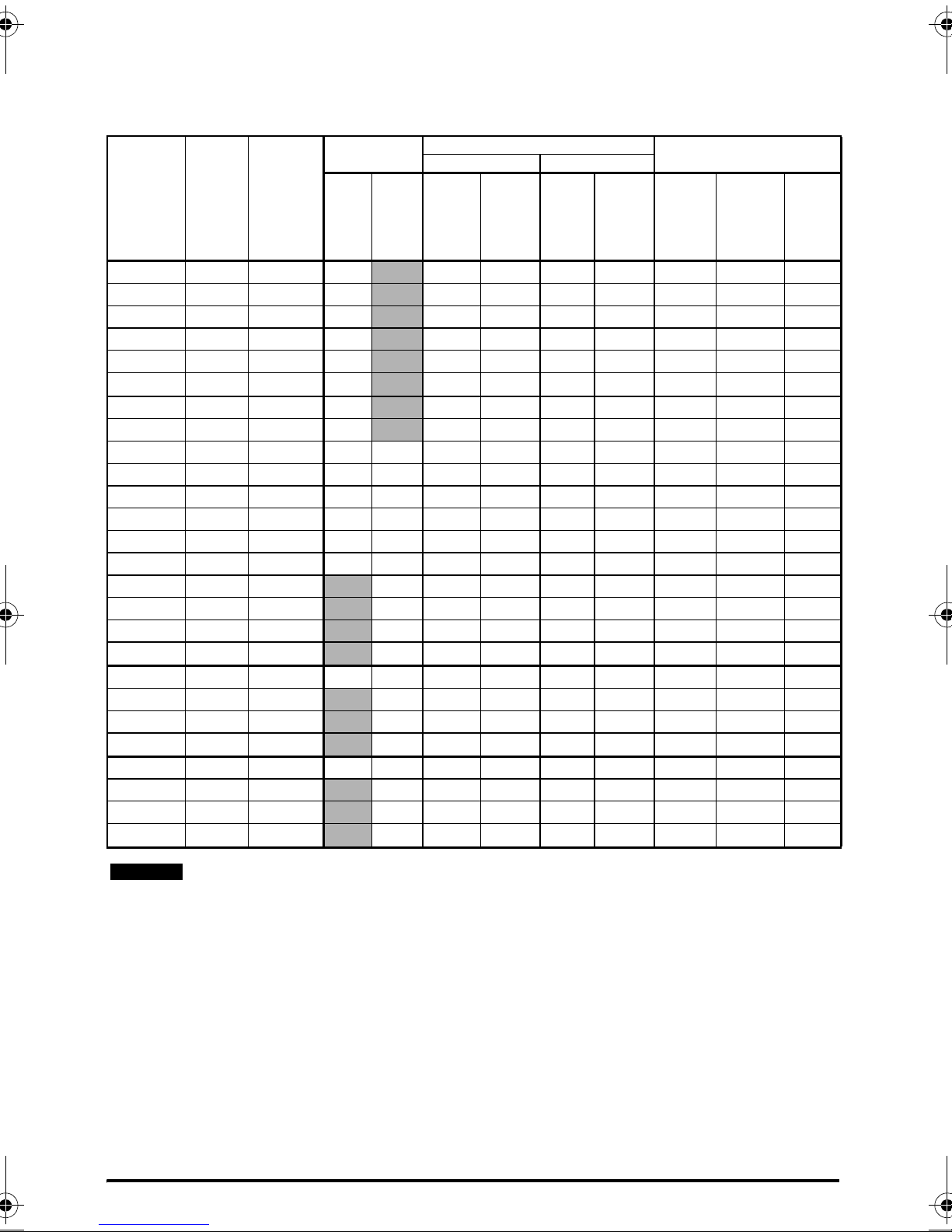
1.1 Ratings
Max input
Max.
Input
Model
01100017 1 8.7 10 1 1 16 16 1.7 0.25 0.33
01100024 1 11.1 16
01200017 1 4.5 6
01200024 1 5.3 6
01200033 1 8.3 10
01200042 1 10.4 16
02100042 1 18.8 20
02100056 1 24 25
02200024 1 / 3 5.3/4.1 6 6 1 1 16 16 2.4 0.37 0.5
02200033 1 / 3 8.3/6.7 10 10 1 1 16 16 3.3 0.55 0.75
02200042 1 / 3 10.4/7.5 16 10 1 1 16 16 4.2 0.75 1
02200056 1 / 3 14.9/11.3 20 15 2.5/1.5 1 12/14 16 5.6 1.1 1.5
02200075 1 / 3 18.1/13.5 20 15 2.5 1 12 16 7.5 1.5 2
02400013 3 2.4 6 1 1 16 16 1.3 0.37 0.5
02400018 3 2.9
02400023 3 3.5
02400032 3 5.1
02400041 3 6.2
03200100 1 / 3 23.9/17.7 25 20 4 1.5 10/12 14 10 2.2 3
03400056 3 8.7
03400073 3 12.2
03400094 3 14.8
04200133 1 / 3 23.7/16.9 25 20 4/2.5 2.5 10 12 13.3 3 3
04200176 3 21.3
04400135 3 16.3
04400170 3 20.7
phases
ph A A A
cont
input
current
fuse rating
1 Ph 3 Ph Input Output Input Output
6 1 1 16 16 1.8 0.55 0.75
6 1 1 16 16 2.3 0.75 1
61 116163.21.11.5
10 1 1 16 16 4.1 1.5 2
10 1 1 14 16 5.6 2.2 3
16 1.5 1 12 16 7.3 3 3
16 2.5 1.5 12 14 9.4 4 5
25 4 2.5 10 12 17.6 4 5
20 2.5 2.5 10 12 13.5 5.5 7.5
25 4 2.5 10 12 17 7.5 10
Nominal cable size
European USA
2
mm
1 1 14 16 2.4 0.37 0.5
1 1 16 16 1.7 0.25 0.33
1 1 16 16 2.4 0.37 0.5
1 1 16 16 3.3 0.55 0.75
1 1 16 16 4.2 0.75 1
2.5 1 12 16 4.2 0.75 1
4 1 10 16 5.6 1.1 1.5
mm
2
AWG AWG A kW hp
Output current
Max.
cont
output
current
Nominal
power
Motor
power
The nominal cable sizes shown in the table above, are provided as a guide only. Ensure
that the cables used conform to the local wiring regulations.
Unidrive M300 Quick Start Guide 7
Issue Number: 4
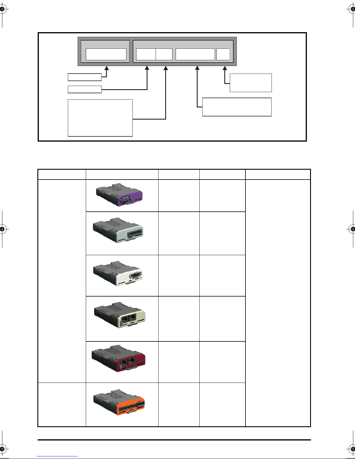
Figure 1-1 Model number structure
Product line:
Frame size:
Current Rating :
Heavy Duty current rating x10
Drive Format :
A – AC in AC out
Voltage rating
:
1 - 100 V (100 - 120 10 %)±
2 - 200 V (200 - 240 10 %)±
4 - 400 V (380 - 480 10 %)±
5 - 575 V (500 - 575 10 %)±
6 - 690 V (500 - 690 10 %)±
Derivative
Electrical Specifications
M300 - 03 4 00073 A
2Options
Table 2-1 System Integration (SI) option module identification
Type Option module Color Name Further details
Purple SI-PROFIBUS
Fieldbus
Medium
Grey
Light Grey SI-CANopen
Beige SI-Ethernet
Brown Red SI-EtherCAT
SI-DeviceNet
See relevant option
module User Guide
Automation
(I/O expansion)
8 Unidrive M300 Quick Start Guide
Orange SI-I/O
Issue Number: 4
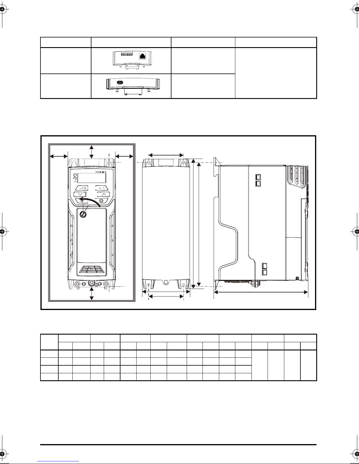
Table 2-2 Adaptor Interface (AI) option module identification
A
W
M2
M2
B
D
B
A
HM1
Cover
release
Type Option module Name Further Details
Communications AI-485 Adaptor
See Drive User Guide
Backup AI-Backup Adaptor
3 Mechanical installation
The drives can be panel mounted with 0 mm space between the drives. For further information on
mechanical installation refer to the Drive User Guide.
To remove the terminal cover, use a flat bladed screwdriver to rotate the terminal cover locating clip
by approximately 30° in a counter clockwise direction, and then slide the cover down.
Drive
Size
1 160 6.30 75 2.95 130 5.12 143 5.70 53 2.08 5 0.2
2 205 8.07 78 3.07 150 5.91 194 7.63 55 2.17 5 0.2
3 226 8.90 90 3.54 160 6.30 215 8.46 70.7 2.80 5 0.2
4 277 10.91 115 4.53 175 6.89 265 10.43 86 3.40 6 0.23
Unidrive M300 Quick Start Guide 9
Issue Number: 4
HWD M1M2∅ AB
mm in mm in mm in mm in mm in mm in mm in mm in
0.00 0.00 100 3.93
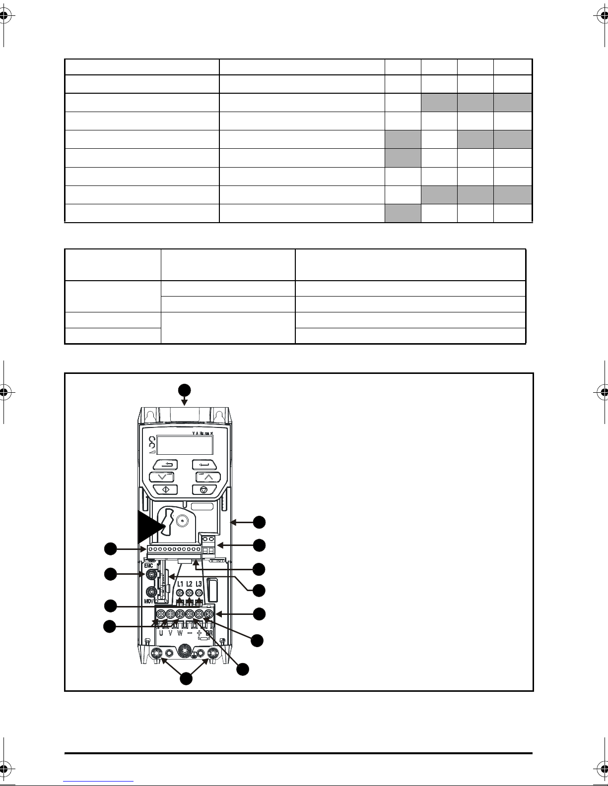
Table 3-1 Tools required
6
8
9
5
7
12
4
1
3
2
11
10
2
13
3
Key
1. Rating label (On side of drive)
2. Identification label
3. Option module connection
4. Relay connections
5. Control connections
6. Braking terminal
7. Internal EMC filter screw
8. DC bus +
9. DC bus -
10. Motor connections
11. AC supply connections
12. Ground connections
13. SAFE TORQUE OFF connections
Tool Location Size 1 Size 2 Size 3 Size 4
Small terminal screwdriver Control, relay and STO terminals
3mm Flat-bladed screwdriver Power terminals
5mm Flat-bladed screwdriver Terminal cover
Pozidrive 1 screwdriver AC power terminals
Pozidrive 2 screwdriver Power terminals
Torx 10 driver EMC & MOV screws
Torx 15 driver Fan screw
Torx 20 driver Fan screw
Table 3-2 Recommended torque settings
Model size
All
1
2, 3, 4 1.4 N m (1.03 Ib ft)
Figure 3-1 Feature diagram (size 2 shown)
Terminal block
description
Control terminals 0.2 N m (0.15 Ib ft)
Relay terminals 0.5 N m (0.37 Ib ft)
Power terminals
9999
9
9999
9
999
9999
9
999
Torque settings
0.5 N m (0.37 Ib ft)
10 Unidrive M300 Quick Start Guide
Issue Number: 4
4 Electrical installation
NOTE
WARNING
An overlay of the electrical connections / terminals is included on the back page of this manual.
4.1 AC supply requirements
Voltage:
100 V drive: 100 V to 120 V ±10 %
200 V drive: 200 V to 240 V ±10 %
400 V drive: 380 V to 480 V ±10 %
Number of phases: 3
Maximum supply imbalance: 2 % negative phase sequence (equivalent to 3 % voltage imbalance
between phases).
Frequency range: 48 to 62 Hz
For UL compliance only, the maximum supply symmetrical fault current must be limited to 100 kA.
On the size 2 110 V drives or when connecting single phase to a dual rated 200 V unit, the
supply should be connected to L1 and L3.
4.2 External braking resistor
Overload protection
When an external braking resistor is used, it is essential that an overload protection device
is incorporated in the braking resistor circuit; as shown in the electrical diagram on the
back cover.
4.2.1 Minimum resistance values and peak power rating for the braking resistor
at 40 °C (104 °F)
Table 4-1 Braking resistor resistance and power rating (100 V)
Minimum
Model
01100017
01100024 0.37
02100042
02100056 1.1
resistance*
Ω
130 1.2
68 2.2
Instantaneous
power rating
kW
Continuous
power rating
kW
0.25
0.75
Unidrive M300 Quick Start Guide 11
Issue Number: 4
 Loading...