

Page 1
Installation Guide
Unidrive M /
Unidrive HS Modular
Model sizes 9 to 11
Universal Variable Speed AC drive
Modular Solutions for induction and
permanent magnet motors
Part Number: 0478-0141-05
Issue: 5
Page 2

Original Instructions
For the purposes of compliance with the EU Machinery Directive 2006/42/EC
General information
This guide covers the basic information that is required to install the drive, in applications where a drive malfunction does not result in
a mechanical hazard. When the drive is used in a safety related application, i.e. where a malfunction might result in a hazard, it is
essential to refer to this guide and the Control User Guide. The Control User Guide is available for download from:
http://www.emersonindustrial.com/en-EN/controltechniques/downloads/userguidesandsoftware/Pages/downloads.aspx
or
www.emersonindustrial.com/en-EN/leroy-somer-motors-drives/downloads/Pages/manuals.aspx
The manufacturer accepts no liability for any consequences resulting from inappropriate, negligent or incorrect installation or
adjustment of the optional operating parameters of the equipment or from mismatching the variable speed drive with the motor.
The contents of this guide are believed to be correct at the time of printing. In the interests of a commitment to a policy of continuous
development and improvement, the manufacturer reserves the right to change the specification of the product or its performance, or
the contents of the guide, without notice.
All rights reserved. No parts of this guide may be reproduced or transmitted in any form or by any means, electrical or mechanical
including photocopying, recording or by an information storage or retrieval system, without permission in writing from the publisher.
Drive firmware version
This product is supplied with the latest firmware version. If this drive is to be connected to an existing system or machine, all drive
firmware versions should be verified to confirm the same functionality as drives of the same model already present. This may also
apply to drives returned from an Emerson Industrial Automation Service Centre or Repair Centre. If there is any doubt please contact
the supplier of the product.
The firmware version of the drive can be checked by looking at Pr 11.029
Environmental statement
Emerson Industrial Automation is committed to minimising the environmental impacts of its manufacturing operations and of its
products throughout their life cycle. To this end, we operate an Environmental Management System (EMS) which is certified to the
International Standard ISO 14001. Further information on the EMS, our Environmental Policy and other relevant information is
available on request, or can be found at:
http://www.emersonindustrial.com/en-EN/controltechniques/aboutus/environment/Pages/environment.aspx.
The electronic variable-speed drives manufactured by Emerson Industrial Automation have the potential to save energy and (through
increased machine/process efficiency) reduce raw material consumption and scrap throughout their long working lifetime. In typical
applications, these positive environmental effects far outweigh the negative impacts of product manufacture and end-of-life disposal.
Nevertheless, when the products eventually reach the end of their useful life, they must not be discarded but should instead be
recycled by a specialist recycler of electronic equipment. Recyclers will find the products easy to dismantle into their major component
parts for efficient recycling. Many parts snap together and can be separated without the use of tools, while other parts are secured
with conventional fasteners. Virtually all parts of the product are suitable for recycling.
Product packaging is of good quality and can be re-used. Large products are packed in wooden crates, while smaller products come
in strong cardboard cartons which themselves have a high recycled fibre content. If not re-used, these containers can be recycled.
Polythene, used on the protective film and bags for wrapping product, can be recycled in the same way. Emerson Industrial
Automation’s packaging strategy prefers easily-recyclable materials of low environmental impact, and regular reviews identify
opportunities for improvement.
When preparing to recycle or dispose of any product or packaging, please observe local legislation and best practice.
REACH legislation
EC Regulation 1907/2006 on the Registration, Evaluation, Authorisation and restriction of Chemicals (REACH) requires the supplier
of an article to inform the recipient if it contains more than a specified proportion of any substance which is considered by the European
Chemicals Agency (ECHA) to be a Substance of Very High Concern (SVHC) and is therefore listed by them as a candidate for
compulsory authorisation.
For current information on how this requirement applies in relation to specific Emerson Industrial Automation’s products, please
approach your usual contact in the first instance. Emerson Industrial Automation’s position statement can be viewed at:
www.emersonindustrial.com/en-EN/controltechniques/aboutus/environment/reachregulation/Pages/reachregulation.aspx.
Copyright © May 2016 Emerson Industrial Automation.
The information contained in this guide is for guidance only and does not form part of any contract. The accuracy cannot be guaranteed
as Emerson have an ongoing process of development and reserve the right to change the specification of their products without notice.
Control Techniques Limited. Registered Office: The Gro, Newtown, Powys SY16 3BE. Registered in England and Wales. Company
Reg. No. 01236886.
Moteurs Leroy-Somer SAS. Headquarters: Bd Marcellin Leroy, CS 10015, 16915 Angoulême Cedex 9, France. Share Capital: 65
800 512 €, RCS Angoulême 338 567 258.
Issue Number: 5
Drive Firmware: 01.13.02.00
Page 3
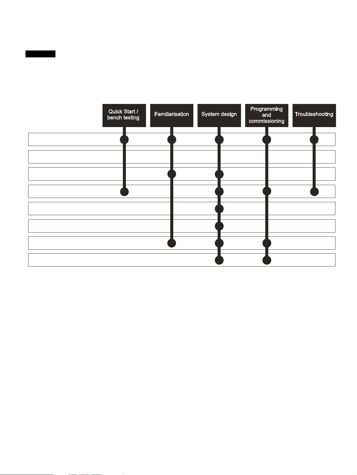
How to use this guide
NOTE
1 Safety information
2 Introduction
3 Product information
4 System configuration
5 Mechanical Installation
6 Electrical installation
7 Technical data
8 UL information
This installation guide provides complete information for installing and operating the drive from start to finish.
The information is in logical order, taking the reader from receiving the drive through to fine tuning the performance.
There are specific safety warnings throughout this guide, located in the relevant sections. In addition, Chapter 1 Safety
information contains general safety information. It is essential that the warnings are observed and the information
considered when working with or designing a system using the drive.
This map of the installation guide helps to find the right sections for the task you wish to complete, but for specific
information, refer to Contents on page 4:
Page 4

Contents
EU Declaration of Conformity ................. 5
EU Declaration of Conformity
(including 2006 Machinery Directive) ..... 6
1 Safety information .................................8
1.1 Warnings, Cautions and Notes .............................8
1.2 Electrical safety - general warning ........................8
1.3 System design and safety of personnel ................8
1.4 Environmental limits ..............................................8
1.5 Access ...................................................................8
1.6 Fire protection .......................................................8
1.7 Compliance with regulations .................................8
1.8 Motor .....................................................................8
1.9 Mechanical brake control ......................................8
1.10 Adjusting parameters ............................................8
1.11 Electrical installation ..............................................9
2 Introduction ..........................................10
2.1 Rectifier ..............................................................10
2.2 Size 9A drives .....................................................11
2.3 Size 9E, 10E and 11E drives ..............................12
2.4 Size 9D, 10D and 11D inverters ..........................13
2.5 Size 9T, 10T and 11T drives ...............................13
2.6 Input line reactor .................................................14
2.7 Output sharing choke ..........................................14
2.8 Model number .....................................................15
3 Product information ............................16
3.1 Ratings ................................................................16
3.2 Operating modes .................................................19
3.3 Nameplate description ........................................22
3.4 Supplied items .....................................................25
4 System configuration ..........................27
5 Mechanical Installation .......................39
5.1 Safety information ...............................................39
5.2 Planning the installation ......................................39
5.3 Terminal cover removal .......................................40
5.4 Mounting of the control master/follower/
standard pod .......................................................44
5.5 Dimensions and mounting methods ....................47
5.6 Enclosure ............................................................61
5.7 Heatsink fan operation ........................................67
5.8 Enclosing drive for high environmental
protection ............................................................68
5.9 External EMC filter ..............................................70
5.10 Line reactor mounting dimensions ......................74
5.11 Electrical terminals ..............................................77
5.12 Routine maintenance ..........................................79
6 Electrical Installation .......................... 85
6.1 Power connections ............................................. 86
6.2 AC supply requirements ..................................... 92
6.3 Output sharing choke specification .................... 95
6.4 Supplying the Unidrive M/Unidrive HS size
9A, 9D, 10D and 11D drives with
DC / DC bus paralleling ...................................... 96
6.5 Heatsink fan supply ............................................ 96
6.6 24 Vdc supply ..................................................... 96
6.7 Low voltage operation ........................................ 98
6.8 Status LED ......................................................... 98
6.9 Ratings ............................................................... 99
6.10 Output circuit and motor protection .................. 103
6.11 Braking ............................................................. 105
6.12 Ground leakage ................................................ 107
6.13 EMC (Electromagnetic compatibility) ............... 108
6.14 Communication connections ............................ 116
6.15 Control connections ......................................... 117
6.16 M70X/HS7X Position feedback connections .... 124
6.17 Safe Torque Off (STO) ..................................... 131
7 Technical data ................................... 133
7.1 Drive technical data .......................................... 133
7.2 Optional external EMC filters ........................... 151
8 UL Information .................................. 153
8.1 UL file reference ............................................... 153
8.2 Option modules, kits and accessories .............. 153
8.3 Enclosure ratings ............................................. 153
8.4 Mounting .......................................................... 153
8.5 Environment ..................................................... 153
8.6 Electrical Installation ........................................ 153
8.7 Motor overload protection and thermal memory
retention ........................................................... 154
8.8 Electrical supply ............................................... 154
8.9 External Class 2 supply .................................... 154
8.10 Requirement for Transient Surge Suppression 154
8.11 Group Installation and Modular Drive Systems 154
Index .................................................. 155
4 Unidrive M / Unidrive HS Modular Installation Guide
Issue Number: 5
Page 5
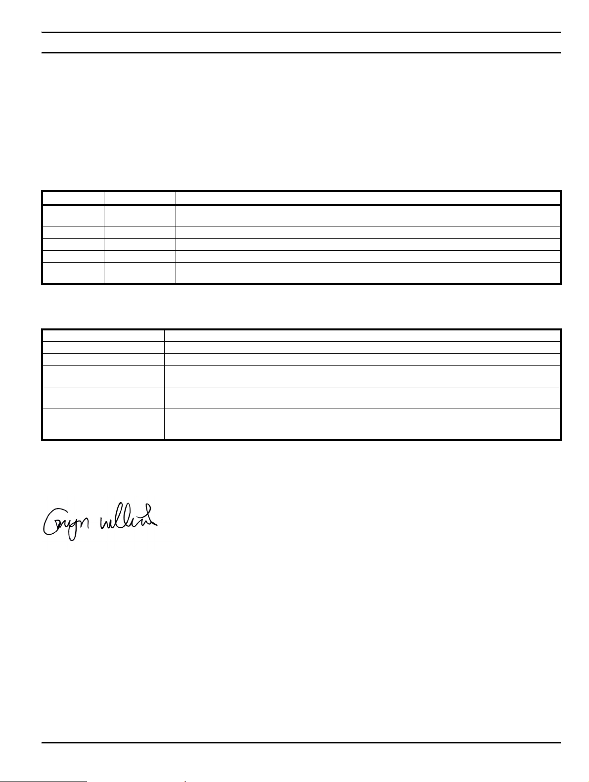
EU Declaration of Conformity
Control Techniques Ltd
The Gro
Newtown
Powys
UK
SY16 3BE
This declaration is issued under the sole responsibility of the manufacturer. The object of the declaration is in conformity with the relevant Union
harmonization legislation. The declaration applies to the variable speed drive products shown below:
Model number Interpretation Nomenclature aaaa - bbc ddddde
aaaa Basic series
bb Frame size 01, 02, 03, 04, 05, 06, 07, 08, 09, 10, 11
c Voltage rating 1 = 100 V, 2 = 200 V, 4 = 400 V, 5 = 575 V, 6 = 690 V
ddddd Current rating Example 01000 = 100 A
e Drive format
The model number may be followed by additional characters that do not affect the ratings.
The variable speed drive products listed above have been designed and manufactured in accordance with the following European harmonized
standards:
EN 61800-5-1:2007 Adjustable speed electrical power drive systems - Part 5-1: Safety requirements - Electrical, thermal and energy
EN 61800-3: 2004+A1:2012 Adjustable speed electrical power drive systems - Part 3: EMC requirements and specific test methods
EN 61000-6-2:2005 Electromagnetic compatibility (EMC) - Part 6-2: Generic standards - Immunity for industrial environments
EN 61000-6-4: 2007+ A1:2011
EN 61000-3-2:2014
EN 61000-3-3:2013
EN 61000-3-2:2014 Applicable where input current < 16 A. No limits apply for professional equipment where input power ≥1 kW.
These products comply with the Restriction of Hazardous Substances Directive (2011/65/EU), the Low Voltage Directive (2014/35/EU) and the
Electromagnetic Compatibility Directive (2014/30/EU).
M100, M101, M200, M201, M300, M400, M600, M700, M701, M702, F300, H300, E200,E300, HS30, HS70,
HS71, HS72, M000, RECT
A = 6P Rectifier + Inverter (internal choke), D = Inverter, E = 6P Rectifier + Inverter (external choke),
T = 12P Rectifier + Inverter (external choke)
Electromagnetic compatibility (EMC) - Part 6-4: Generic standards - Emission standard for industrial
environments
Electromagnetic compatibility (EMC) - Part 3-2: Limits for harmonic current emissions (equipment input current
≤16 A per phase)
Electromagnetic compatibility (EMC) - Part 3-3: Limitation of voltage changes, voltage fluctuations and flicker in
public, low voltage supply systems, for equipment with rated current ≤16 A per phase and not subject to
conditional connection
Moteurs Leroy-Somer
Usine des Agriers
Boulevard Marcellin Leroy
CS10015
16915 Angoulême Cedex 9
France
G Williams
Vice President, Technology
Date: 17th March 2016
These electronic drive products are intended to be used with appropriate motors, controllers, electrical protection components and other
equipment to form complete end products or systems. Compliance with safety and EMC regulations depends upon installing and
configuring drives correctly, including using the specified input filters.
The drives must be installed only by professional installers who are familiar with requirements for safety and EMC. Refer to the Product
Documentation. An EMC data sheet is available giving detailed information. The assembler is responsible for ensuring that the end product
or system complies with all the relevant laws in the country where it is to be used.
Un idrive M / Uni drive H S Modu lar In stall a tion G uide 5
Issue Number: 5
Page 6

EU Declaration of Conformity (including 2006 Machinery Directive)
Control Techniques Ltd
The Gro
Newtown
Powys
UK
SY16 3BE
This declaration is issued under the sole responsibility of the manufacturer. The object of the declaration is in conformity with the relevant Union
harmonization legislation. The declaration applies to the variable speed drive products shown below:
Model No. Interpretation Nomenclature aaaa - bbc ddddde
aaaa Basic series M300, M400, M600, M700, M701, M702, F300, H300, E200, E300, HS30, HS70, HS71, HS72, M000, RECT
bb Frame size 01, 02, 03, 04, 05, 06, 07, 08, 09, 10, 11
c Voltage rating 1 = 100 V, 2 = 200 V, 4 = 400 V, 5 = 575 V, 6 = 690 V
ddddd Current rating Example 01000 = 100 A
e Drive format
The model number may be followed by additional characters that do not affect the ratings.
This declaration relates to these products when used as a safety component of a machine. Only the Safe Torque Off function may be used
for a safety function of a machine. None of the other functions of the drive may be used to carry out a safety function.
These products fulfil all the relevant provisions of the Machinery Directive 2006/42/EC and the Electromagnetic Compatibility Directive (2014/30/EU).
EC type examination has been carried out by the following notified body:
TUV Rheinland Industrie Service GmbH
Am Grauen Stein
D-51105 Köln
Germany
A = 6P Rectifier + Inverter (internal choke), D = Inverter, E = 6P Rectifier + Inverter (external choke), T = 12P
Rectifier + Inverter (external choke)
Moteurs Leroy-Somer
Usine des Agriers
Boulevard Marcellin Leroy
CS10015
16915 Angoulême Cedex 9
France
EC type-examination certificate numbers:
01/205/5270.01/14 dated 2014-11-11
01/205/5387.01/15 dated 2015-01-29
01/205/5383.02/15 dated 2015-04-21
Notified body identification number: 0035
The harmonized standards used are shown below:
EN 61800-5-1:2007 Adjustable speed electrical power drive systems - Part 5-1: Safety requirements - Electrical, thermal and energy
EN 61800-5-2:2007 Adjustable speed electrical power drive systems - Part 5-2: Safety requirements - Functional
EN ISO 13849-1:2008 Safety of Machinery, Safety-related parts of control systems, General principles for design
EN ISO 13849-2:2008 Safety of machinery, Safety-related parts of control systems. Validation
EN 61800-3: 2004+A1:2012 Adjustable speed electrical power drive systems - Part 3: EMC requirements and specific test methods
EN 62061:2005
Person authorised to complete the technical file:
P Knight
Conformity Engineer
Newtown, Powys, UK
Safety of machinery, Functional safety of safety related electrical, electronic and programmable electronic control
systems
6 Unidrive M / Unidrive HS Modular Installation Guide
Issue Number: 5
Page 7

G. Williams
Vice President, Technology
Date: 17th March 2016
Place: Newtown, Powys, UK
IMPORTANT NOTICE
These electronic drive products are intended to be used with appropriate motors, controllers, electrical protection components and other
equipment to form complete end products or systems. Compliance with safety and EMC regulations depends upon installing and
configuring drives correctly, including using the specified input filters.
The drives must be installed only by professional installers who are familiar with requirements for safety and EMC. Refer to the Product
Documentation. An EMC data sheet is available giving detailed information. The assembler is responsible for ensuring that the end product
or system complies with all the relevant laws in the country where it is to be used.
Unidrive M / Unidrive HS Modular Installation Guide 7
Issue Number: 5
Page 8

Safety
WARNING
CAUTION
NOTE
information
Introduction Product information
System
configuration
1 Safety information
1.1 Warnings, Cautions and Notes
A Warning contains information which is essential for
avoiding a safety hazard.
A Caution contains information which is necessary for
avoiding a risk of damage to the product or other equipment.
A Note contains information which helps to ensure correct operation of
the product.
1.2 Electrical safety - general warning
The voltages used in the drive can cause severe electrical shock and/or
burns, and could be lethal. Extreme care is necessary at all times when
working with or adjacent to the drive.
Specific warnings are given at the relevant places in this Installation
Guide.
1.3 System design and safety of
The drive is intended as a component for professional incorporation into
complete equipment or a system. If installed incorrectly, the drive may
present a safety hazard.
The drive uses high voltages and currents, carries a high level of stored
electrical energy, and is used to control equipment which can cause
injury.
Close attention is required to the electrical installation and the system
design to avoid hazards either in normal operation or in the event of
equipment malfunction. System design, installation, commissioning/
start-up and maintenance must be carried out by personnel who have
the necessary training and experience. They must read this safety
information and this Installation Guide carefully.
The STOP and Safe Torque Off functions of the drive do not isolate
dangerous voltages from the output of the drive or from any external
option unit. The supply must be disconnected by an approved electrical
isolation device before gaining access to the electrical connections.
With the sole exception of the Safe Torque Off function, none of the
drive functions should be used to ensure safety of personnel, i.e.
they must not be used for safety-related functions.
Careful consideration must be given to the functions of the drive which
might result in a hazard, either through their intended behavior or
through incorrect operation due to a fault. In any application where a
malfunction of the drive or its control system could lead to or allow
damage, loss or injury, a risk analysis must be carried out, and where
necessary, further measures taken to reduce the risk - for example, an
over-speed protection device in case of failure of the speed control, or a
fail-safe mechanical brake in case of loss of motor braking.
The Safe Torque Off function may be used in a safety-related
application. The system designer is responsible for ensuring that the
complete system is safe and designed correctly according to the
relevant safety standards.
personnel
Mechanical
Installation
Electrical
Installation
Technical data UL Information
1.5 Access
Drive access must be restricted to authorized personnel only. Safety
regulations which apply at the place of use must be complied with.
1.6 Fire protection
The drive enclosure is not classified as a fire enclosure. A separate fire
enclosure must be provided. For further information, refer to section
5.2.5 Fire protection on page 39.
1.7 Compliance with regulations
The installer is responsible for complying with all relevant regulations,
such as national wiring regulations, accident prevention regulations and
electromagnetic compatibility (EMC) regulations. Particular attention
must be given to the cross-sectional areas of conductors, the selection
of fuses or other protection, and protective ground (earth) connections.
This Installation Guide contains instruction for achieving compliance with
specific EMC standards.
Within the European Union, all machinery in which this product is used
must comply with the following directives:
Safety of Machinery 2006/42/EC
Electromagnetic Compatibility (EMC) Directive 2014/30/EU
1.8 Motor
Ensure the motor is installed in accordance with the manufacturer’s
recommendations. Ensure the motor shaft is not exposed.
Standard squirrel cage induction motors are designed for single speed
operation. If it is intended to use the capability of the drive to run a motor
at speeds above its designed maximum, it is strongly recommended that
the manufacturer is consulted first.
Low speeds may cause the motor to overheat because the cooling fan
becomes less effective. The motor should be installed with a protection
thermistor. If necessary, an electric forced vent fan should be used.
The values of the motor parameters set in the drive affect the protection
of the motor. The default values in the drive should not be relied upon.
It is essential that the correct value is entered in Pr 00.046 motor rated
current. This affects the thermal protection of the motor.
1.9 Mechanical brake control
The brake control functions are provided to allow well co-ordinated
operation of an external brake with the drive. While both hardware and
software are designed to high standards of quality and robustness, they
are not intended for use as safety functions, i.e. where a fault or failure
would result in a risk of injury. In any application where the incorrect
operation of the brake release mechanism could result in injury,
independent protection devices of proven integrity must also be
incorporated.
1.10 Adjusting parameters
Some parameters have a profound effect on the operation of the drive.
They must not be altered without careful consideration of the impact on
the controlled system. Measures must be taken to prevent unwanted
changes due to error or tampering.
1.4 Environmental limits
Instructions in this Installation Guide regarding transport, storage,
installation and use of the drive must be complied with, including the
specified environmental limits. Drives must not be subjected to
excessive physical force.
8 Unidrive M / Unidrive HS Modular Installation Guide
Issue Number: 5
Page 9

Safety
information
Introduction Product information
System
configuration
1.11 Electrical installation
1.11.1 Electric shock risk
The voltages present in the following locations can cause severe electric
shock and may be lethal:
AC supply cables and connections
Output cables and connections
Many internal parts of the drive, and external option units
Unless otherwise indicated, control terminals are single insulated and
must not be touched.
1.11.2 Stored charge
The drive contains capacitors that remain charged to a potentially lethal
voltage after the AC supply has been disconnected. If the drive has been
energized, the AC supply must be isolated at least ten minutes before
work may continue.
Mechanical
Installation
Electrical
Installation
Technical data UL Information
Unidrive M / Unidrive HS Modular Installation Guide 9
Issue Number: 5
Page 10
Safety information Introduction Product information
CAUTION
L3
+DC
-DC
L2
L1
+DC
-DC
L1
L1
L2
L2
L3
L3
System
configuration
Mechanical
Installation
Electrical
Installation
Technical data UL Information
2 Introduction
The Unidrive M / Unidrive HS modular drive offers the possibility of implementing many custom power systems with a wide range of power modules.
The power range is 110 kW to 2.8 MW and the modular design of input and output stages enables a wide range of very compact and efficient systems
to be realized. These include:
• Parallel output stages for higher power motors:
Size 9 and 10:
Up to a maximum of 20 modules
(1 master module with up to 19 follower modules, OR
1 remote mounted control master pod controlling up to 20 followers. This allows the user to place all control circuitry in one low voltage
cabinet)
Size 11:
Up to a maximum of 10 modules
(1 master module with up to 9 follower modules OR 1 remote mounted control master pod controlling up to 10 followers).
• Common DC bus multi-drive systems for:
Connection to larger existing power supplies
Energy sharing between motoring and regenerating drives
• Active front end drive systems for:
Minimizing supply current harmonics
Four quadrant motor control
• Multiple controlled rectifier bridges for:
Minimizing supply current harmonics by drawing 6, 12 or 18 pulse supply load currents.
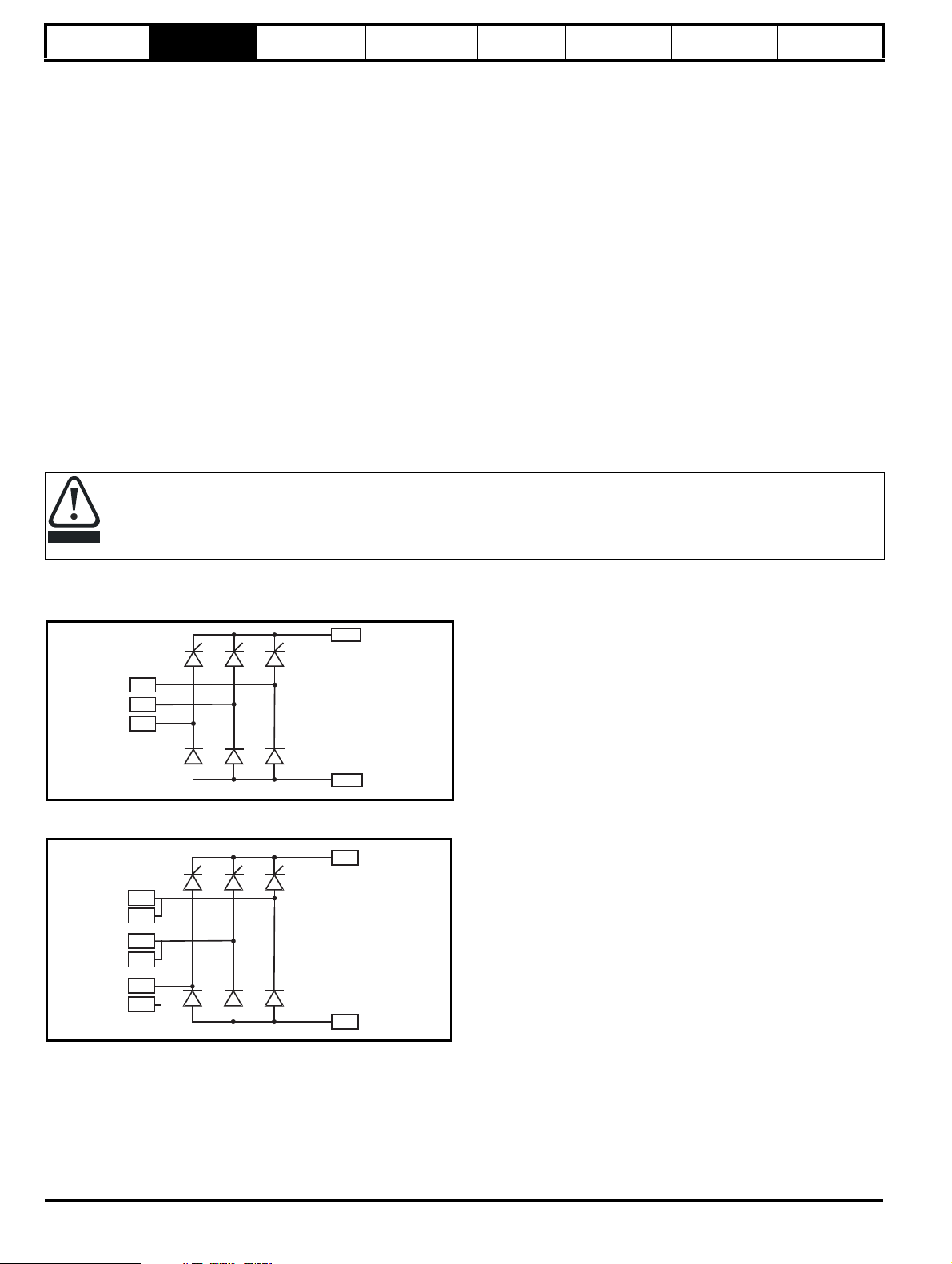
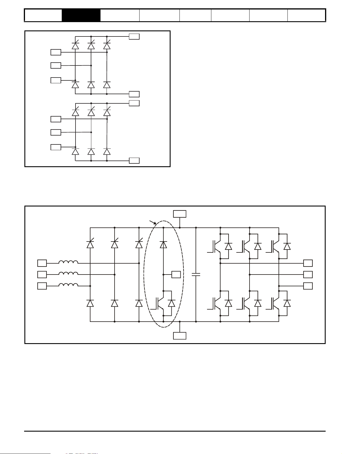
2.1 Rectifier
A separate input line reactor (INLXXX) of at least the value shown in Table 6-2 Model and line reactor part numbers on page 93 must be
used with the rectifiers. Failure to provide sufficient reactance could damage or reduce the service life of the rectifier or inverter.
The Unidrive M / Unidrive HS rectifier is a half controlled SCR/thyristor bridge and is used as a front end to the size 9, size 10 or size 11 inverter
module. The rectifier cannot be used as a stand alone rectifier for several smaller drives.
Figure 2-1 Frame 10 single half controlled SCR/thyristor
Figure 2-2 Frame 11 single half controlled SCR/thyristor
10 Unidrive M / Unidrive HS Modular Installation Guide
Issue Number: 5
Page 11
Safety information Introduction Product information
+DC
-DC
+DC
-DC
L1
L2
L3
L1
L2
L3
L1
L2
L3
BR
U
V
W
+DC
-DC
Optional
System
configuration
Mechanical
Installation
Electrical
Installation
Technical data UL Information
Figure 2-3 Frame 11 twin half controlled SCR/thyristor
2.2 Size 9A drives
The size 9A is a complete drive with internal rectifier and AC input line chokes (AC in to AC out). It can provide a maximum continuous output current
of 266 A (400 V drive). DC connections are available for use in regen and bus-parallel applications. The size 9A is available with or without a braking
IGBT installed.
Figure 2-4 Size 9A inverter schematic
Unidrive M / Unidrive HS Modular Installation Guide 11
Issue Number: 5
Page 12
Safety information Introduction Product information
L1
L2
L3
BR
U
V
W
+DC
Optional
L1
L2
L3
BR
U
V
W
+DC
Optional
L1
L2
L3
System
configuration
Mechanical
Installation
Electrical
Installation
Technical data UL Information
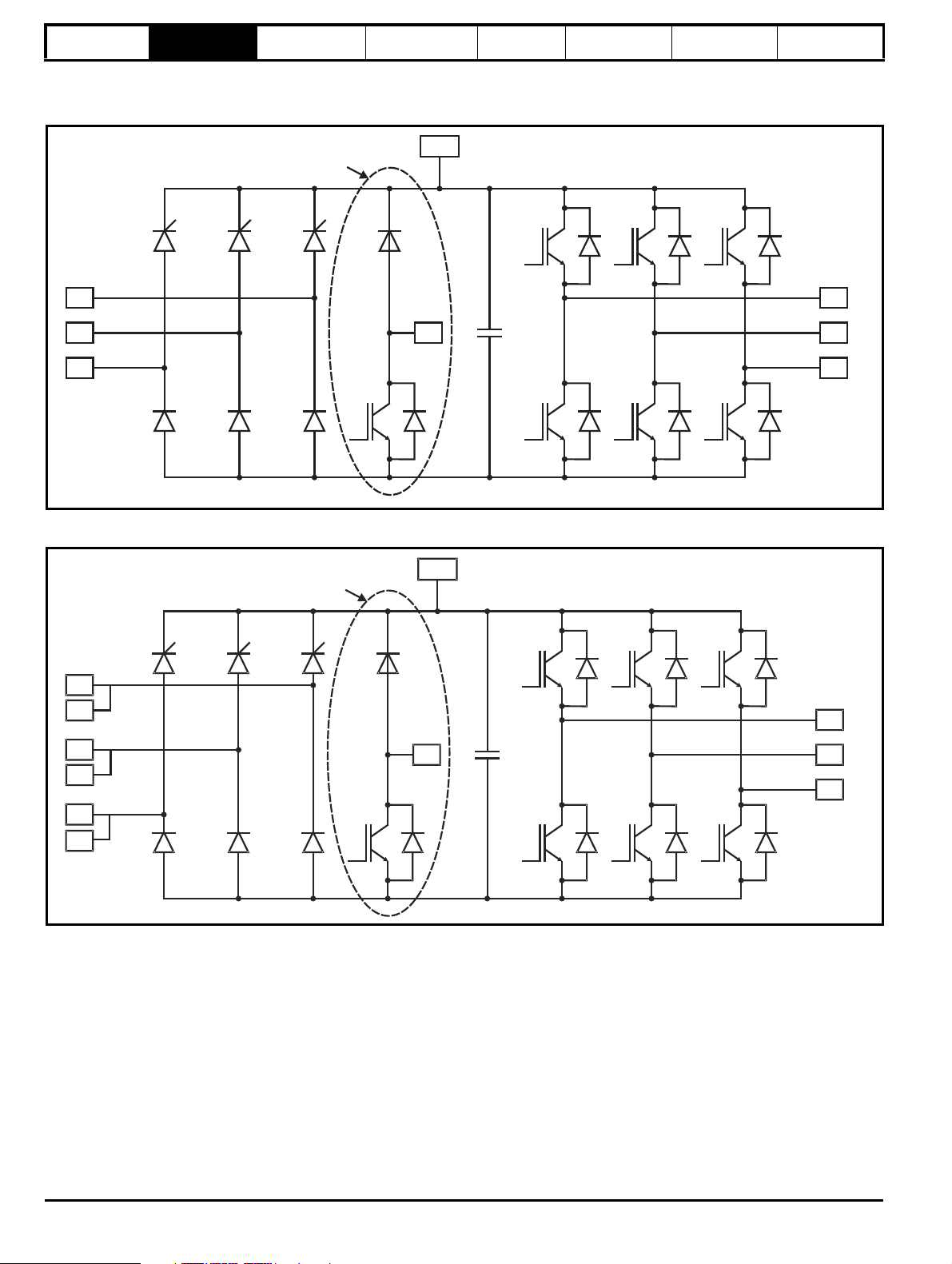
2.3 Size 9E, 10E and 11E drives
The size 9E,10E and 11E are complete drives with internal rectifier (AC in to AC out). External AC line chokes are required.
Figure 2-5 Size 9E and 10E inverter schematic
Figure 2-6 Size 11E inverter schematic
12 Unidrive M / Unidrive HS Modular Installation Guide
Issue Number: 5
Page 13
Safety information Introduction Product information
BR
U
V
W
-DC
+DC
Optional
+DC
-DC
NOTE
U
V
W
BR
+DC
Optional
L1
L2
L3
L1
L2
L3
System
configuration
Mechanical
Installation
Electrical
Installation
Technical data UL Information
2.4 Size 9D, 10D and 11D inverters
Size 9D, 10D and 11D are inverter stage only (DC in to AC out). If a rectifier is required, then an AC input line reactor must also be installed. DC
connections can be used for regen and bus-parallel applications. Size 9D, 10D and 11D are available with or without a braking IGBT installed.
Figure 2-7 Size 9D, 10D and 11D inverter schematic
The above diagram shows size 11D which has double DC terminals, size 9D and 10D have single DC terminals.
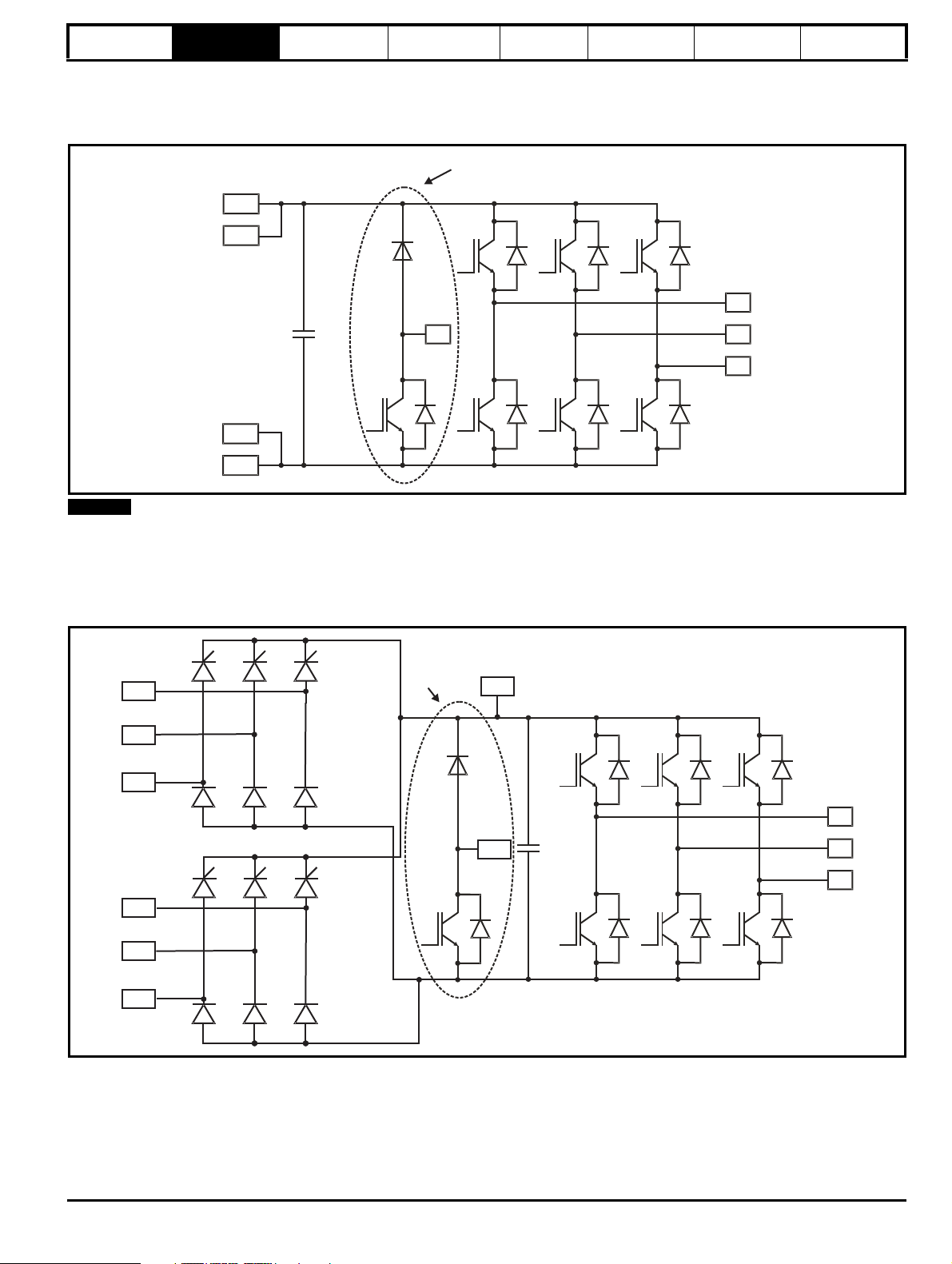
2.5 Size 9T, 10T and 11T drives
Size 9T, 10T and 11T are complete drives with internal 12 pulse rectifier (AC in to AC out). External AC line chokes are required unless the required
reactance is incorporated into a 12 pulse transformer.
Figure 2-8 Size 9T, 10T and 11T inverter schematic
Unidrive M / Unidrive HS Modular Installation Guide 13
Issue Number: 5
Page 14
Safety information Introduction Product information
L1
L2
L3
L1A
L2A
L3A
U1
V1
W1
U2
V2
W2
UVW
UVW
U1 U2
V1 V2
W1 W2
Drive 1
Drive 2
U1
V1
W1
U2
V2
W2
System
configuration
Mechanical
Installation
Electrical
Installation
Technical data UL Information
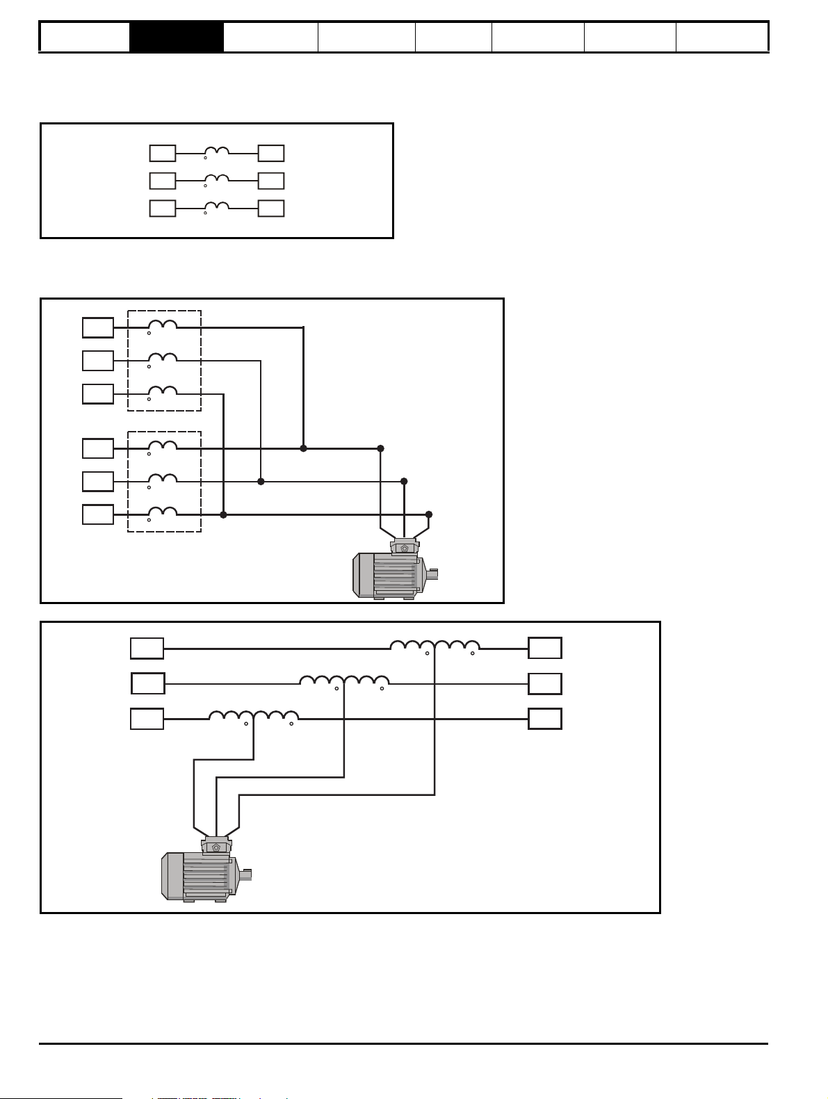
2.6 Input line reactor
The INL line reactor must be used in conjunction with the Unidrive M / Unidrive HS rectifiers. See section 6.2.2 Input line reactor specifications on
page 93 for further information.
Figure 2-9 Single input line reactor (INLX0X)/force cooled (INLX0XW)
2.7 Output sharing choke
The OTL output sharing choke must be used on the output of Unidrive M / Unidrive HS when more than one module is paralleled together.
Figure 2-10 Single output sharing choke (OTLX0X) - two chokes shown
Figure 2-11 Dual output sharing choke (OTLX1X)
For a physical representation of the input line reactors and output sharing chokes, see section 2.6 and section 2.7 Output sharing choke on page 14.
14 Unidrive M / Unidrive HS Modular Installation Guide
Issue Number: 5
Page 15
Safety information Introduction Product information
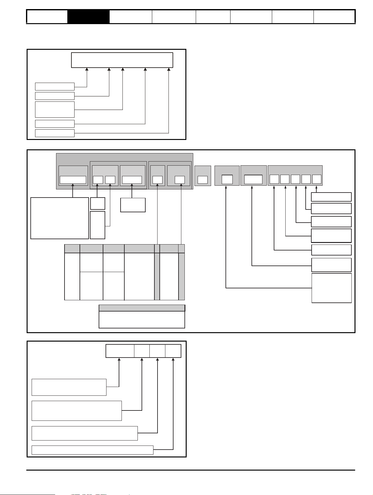
RECT
10 6 02480
A
Model
Frame size
Voltage 2=200 V
4=400 V
6=690 V
Current rating
Rectifier format
Identification Label
Unidrive Range:
M600- EIA 485
M700- Ethernet
M701- EIA 485
M702- Ethernet, 2 x STO
HS70- Ethernet, High speed
HS71- EIA 485, High speed
HS72- Ethernet, 2 x STO, High speed
Range &
Derivative
Power
Format
Mxxx-
09
4
02240
Configuration
1
Electrical Specifications Drive Format
Frame & Volts
Frames
Power
Description
Power Format
Control
Unassigned
Range ID
Frame
size
Current rating:
Heavy duty
rating x 10
Voltage
rating:
2=200 V
4=400 V
5=575 V
6=690 V
Current
A
0
09 to 11
AC to AC
DC to AC
Single drives
Mxxx-
Modular drives
M000-
(Unassigned
power stage
with no control
fitted)
E
1
U
Standard
M000-FOLLOWER011100A0100
Mxxx-MASTER00011100A0100
Mxxx- STANDARD011100A0100
Control Module Range for Unassigned Modular Drives
MMaster
D
FFollower
A
AC to AC integrated
Rectifier, Inverter.
Internal line choke
AC to AC integrated
Rectifier, Inverter.
External line choke
DC to AC Inverter
T
12P Rectifier plus
Inverter
Reserved
Optional Build
Customer Code
01
A B
1
00
Customer Code
:
00 =
50
Hz
01 =60Hz
Reserved:
Conformal Coating:
0=Standard
IP /NEMARating:
1 =IP20 / NEMA 1
Brake Transistor:
B = Brake
Cooling
:
A=
Air
Documentation
1
Documentation:
0 - Supplied separately
1 - English
2 - French
3 - Italian
4 - German
5 - Spanish
N = No Brake
INL:
Current rating step
OTL: Output sharing choke
INL
4 0 1
Input line reactor
0: Single
1: Dual
Voltage rating
4: 380V to 480V
6: 500V to 690V
System
configuration
Mechanical
Installation
2.8 Model number
The model numbers for the Unidrive M / Unidrive HS range are formed as illustrated below.
Figure 2-12 Rectifier model number
Figure 2-13 Drive model number
Electrical
Installation
Technical data UL Information
Figure 2-14 Input line reactor / output sharing choke
Unidrive M / Unidrive HS Modular Installation Guide 15
Issue Number: 5
Page 16
Safety information Introduction
Available output
current
Overload limit -
Heavy Duty
Maximum
continuous
current (above
50% base
speed) -
Normal Duty
Maximum
continuous
current -
Heavy Duty
Motor rated
current set
in the drive
Heavy Duty
- with high
overload capability
Normal Duty
Overload limit -
Normal Duty
NOTE
NOTE
Motor total
current (Pr 04.001)
as a percentage
of motor rated
current
Motor speed as a
percentage of base speed
100%
Max. permissible
continuous
current
100%
I t protection operates in this region
2
70%
50%15%
Pr = 0
Pr = 1
04.025
04.025
Motor total
current (Pr 04.001)
as a percentage
of motor rated
current
Motor speed as a
percentage of base speed
100%
Max. permissible
continuous
current
100%
I t protection operates in this region
2
70%
50%
Pr = 0
Pr = 1
04.025
04.025
Product
information
System
configuration
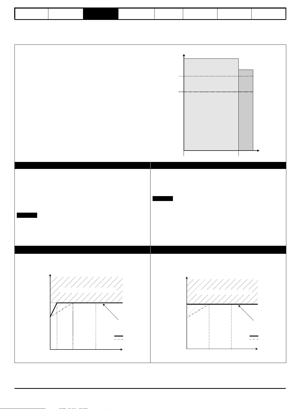
3 Product information
3.1 Ratings
The drive is dual rated.
The setting of the motor rated current determines which rating applies Heavy Duty or Normal Duty.
The two ratings are compatible with motors designed to IEC60034.
The graph aside illustrates the difference between Normal Duty and
Heavy Duty with respect to continuous current rating and short term
overload limits.
Mechanical
Installation
Electrical
Installation
Technical data UL Information
Normal Duty Heavy Duty (default)
For applications which use Self ventilated (TENV/TEFC) induction
motors and require a low overload capability, and full torque at low
speeds is not required (e.g. fans, pumps).
Self ventilated (TENV/TEFC) induction motors require increased
protection against overload due to the reduced cooling effect of the fan
at low speed. To provide the correct level of protection the I
operates at a level which is speed dependent. This is illustrated in the
graph below.
The speed at which the low speed protection takes effect can be
changed by the setting of Low Speed Thermal Protection Mode
(04.025). The protection starts when the motor speed is below 15 % of
base speed when Pr 04.025 = 0 (default) and below 50 % when
Pr 04.025 = 1.
Operation of motor I2t protection
Motor I2t protection is fixed as shown below and is compatible with:
• Self ventilated (TENV/TEFC) induction motors
2
t software
For constant torque applications or applications which require a high
overload capability, or full torque is required at low speeds (e.g. winders,
hoists).
The thermal protection is set to protect force ventilated induction motors
and permanent magnet servo motors by default.
N
If the application uses a self ventilated (TENV/TEFC) induction motor
and increased thermal protection is required for speeds below 50 %
base speed, then this can be enabled by setting Low Speed Thermal
Protection Mode (04.025) = 1.
Motor I2t protection defaults to be compatible with:
• Forced ventilation induction motors
• Permanent magnet servo motors
16 Unidrive M / Unidrive HS Modular Installation Guide
Issue Number: 5
Page 17

Safety information Introduction
Product
information
System
configuration
Mechanical
Installation
Electrical
Installation
Technical data UL Information
The continuous current ratings given are for maximum 40 °C (104 °F), 1000 m altitude and 2 kHz switching frequency. Derating is required for higher
switching frequencies, ambient temperature >40 °C (104 °F), high altitude and parallel applications. For further information, refer to section
7.1.1 Power and current ratings (Derating for switching frequency and temperature) on page 133, 5 % derating should be applied when paralleling
two or more inverters.
Table 3-1 Size 9 and 10 200 V drive ratings (200 V to 240 V ±10 %)
Normal Duty Heavy Duty
9A / 9E / 9D
10D / 10E
Maximum
Model
09201760 216 55 75 238 176 264 308 45 60
09202190 266 75 100 293 219 328 383 55 75
10202830 325 90 125 357 283 424 495 75 100
10203000 360 110 150 396 300 450 525 90 125
continuous
output
current
AkWhpA A AAkW hp
Nominal
power at
230 V
Motor
power at
230 V
Peak
current
Maximum
continuous
output
current
Open loop
peak
current
RFC peak
current
Nominal
power at
230 V
Motor
power at
230 V
Table 3-2 Size 9, 10 and 11 400 V drive ratings (380 V to 480 V ±10 %)
Normal Duty Heavy Duty
9A / 9E / 9D
/ 9T
10D / 10E /
10T
11D / 11E /
11T
Maximum
Model
09402000 221 110 150 243 200 300
09402240 266 132 200 293 224 336
10402700 320 160 250 352 270 405
10403200 361 200 300 397 320 480
11403770 437 225 350 481 377 565
11404170 487 250 400 536 417 625
11404640 507 280 450 558 464 696
continuous
output
current
AkWhpA A AAkW hp
Nominal
power at
400 V
Motor
power at
460 V
Peak
current
Maximum
continuous
output
current
Open loop
peak
current
RFC peak
current
350
392
472
560
660
730
812
Nominal
power at
400 V
90 150
110 150
132 200
160 250
185 300
200 350
250 400
Motor
power at
460 V
Table 3-3 Size 9, 10 and 11 575 V drive ratings (500 V to 575 V ±10 %)
Normal Duty Heavy Duty
9A / 9E / 9D
/ 9T
10D / 10E /
10T
11D / 11E /
11T
Model
09501040
09501310
10501520
10501900
11502000
11502540
11502850
Maximum
continuous
output
current
AkWhpA A AAkW hp
125 110 125 137 104 156 182 75 100
150 110 150 165 131 196 229 90 125
200 130 200 220 152 228 266 11 0 150
200 150 200 220 190 285 332 132 200
248 185 250 273 200 300 350 150 200
288 225 300 317 254 381 444 185 250
315 250 350 346 285 427 499 225 300
Nominal
power at
575 V
Motor
power at
575 V
Peak
current
Table 3-4 Size 9, 10 and 11 690 V drive ratings (500 V to 690 V ±10 %)
Normal Duty Heavy Duty
9A / 9E / 9D
/ 9T
10D / 10E /
10T
11D / 11E /
11T
Model
09601040
09601310
10601500
10601780
11602100
11602380
11602630
Maximum
continuous
output
current
AkWhpA A AAkW hp
125 110 150 137 104 156 182 90 125
155 132 175 170 131 196 229 11 0 150
172 160 200 189 150 225 262 132 175
197 185 250 217 178 267 311 160 200
225 200 250 247 210 315 367 185 250
275 250 300 302 238 357 416 200 250
305 280 400 335 263 394 460 250 300
Nominal
power at
690 V
Motor
power at
690 V
Peak
current
Maximum
continuous
output
current
Maximum
continuous
output
current
Open loop
peak
current
Open loop
peak
current
RFC peak
current
RFC peak
current
Nominal
power at
575 V
Nominal
power at
690 V
Motor
power at
575 V
Motor
power at
690 V
Unidrive M / Unidrive HS Modular Installation Guide 17
Issue Number: 5
Page 18

Safety information Introduction
NOTE
Product
information
Table 3-5 Rectifier ratings at 40° C (104° F)
System
configuration
Mechanical
Installation
Electrical
Installation
Technical data UL Information
Model
10204100 200
10404520 400
10502430 575
10602480 690
11406840 400
11503840 575
11604060 690
1142X400* 400
1162X380* 690
Vol ta ge r a tin g
VA A A
Typical input
current
333 361 494
370 396 523
202 218 313
202 225 313
557 594 752
313 338 473
331 362 465
2 x 326 2 x 358 2 x 397
2 x 308 2 x 339 2 x 375
Maximum continuous
input current
Maximum overload
input current
Typical continuous
DC output current
AA
409 413
452 455
243 246
247 251
684 689
384 387
406 411
2 x 395 2 x 400
2 x 375 2 x 380
Maximum DC output
current
* Twin rectifier
3.1.1 Typical short term overload limits
The maximum percentage overload limit changes depending on the selected motor. Variations in motor rated current, motor power factor and motor
leakage inductance all result in changes in the maximum possible overload. The exact value for a specific motor can be calculated using the
equations detailed in Menu 4 in the Parameter Reference Guide.
Typical values are shown in the table below for RFC (RFC-A or RFC-S) and open loop (OL) modes:
Table 3-6 Typical overload limits
Operating mode RFC from cold RFC from 100 %
Normal Duty overload with motor rated current = drive rated
current
Heavy Duty overload with motor rated current = drive rated
current (size 9, 10 and 11)
Open loop from
cold
110 % for 165 s 110 % for 9 s 110 % for 165 s 110 % for 9 s
175 % for 42 s 175 % for 5 s 150 % for 60 s 150 % for 7 s
Open loop from
100 %
Generally the drive rated current is higher than the matching motor rated current allowing a higher level of overload than the default setting.
The time allowed in the overload region is proportionally reduced at very low output frequency on some drive ratings.
The maximum overload level which can be attained is independent of the speed.
18 Unidrive M / Unidrive HS Modular Installation Guide
Issue Number: 5
Page 19

Safety information Introduction
Product
information
System
configuration
Mechanical
Installation
Electrical
Installation
Technical data UL Information
3.2 Operating modes
The drive is designed to operate in any of the following modes:
1. Open loop mode
Open loop vector mode
Fixed V/F mode (V/Hz)
Quadratic V/F mode (V/Hz)
2. RFC - A mode
With position feedback sensor
Without position feedback sensor (Sensorless)
3. RFC - S mode
With position feedback sensor
Without position feedback sensor (Sensorless)
4. Regen mode
3.2.1 Open loop mode
The drive applies power to the motor at frequencies varied by the user. The motor speed is a result of the output frequency of the drive and slip due
to the mechanical load. The drive can improve the speed control of the motor by applying slip compensation. The performance at low speed depends
on whether V/F mode or open loop vector mode is selected.
Open loop vector mode
The voltage applied to the motor is directly proportional to the frequency except at low speed where the drive uses motor parameters to apply the
correct voltage to keep the flux constant under varying load conditions.
Typically 100 % torque is available down to 1 Hz for a 50 Hz motor.
Fixed V/F mode
The voltage applied to the motor is directly proportional to the frequency except at low speed where a voltage boost is provided which is set by the
user. This mode can be used for multi-motor applications.
Typically 100 % torque is available down to 4 Hz for a 50 Hz motor.
Quadratic V/F mode
The voltage applied to the motor is directly proportional to the square of the frequency except at low speed where a voltage boost is provided which is
set by the user. This mode can be used for running fan or pump applications with quadratic load characteristics or for multi-motor applications. This
mode is not suitable for applications requiring a high starting torque.
3.2.2 RFC-A mode
Rotor Flux Control for Asynchronous (induction) motors (RFC-A) encompasses closed loop vector control with a position feedback device
With position feedback
For use with induction motors with a feedback device installed. The drive directly controls the speed of the motor using the feedback device to ensure
the rotor speed exactly as demanded. Motor flux is accurately controlled at all times to provide full torque all the way down to zero speed.
Without position feedback (Sensorless)
Sensorless mode provides closed loop control without the need for position feedback by using current, voltages and key motor parameters to
estimate the motor speed. It can eliminate instability traditionally associated with open loop control such as operating large motors with light loads at
low frequencies.
3.2.3 RFC-S mode
Rotor Flux Control for Synchronous (permanent magnet brushless) motors (RFC-S) provides closed loop control with position feedback device.
With position feedback
For use with permanent magnet brushless motors with a feedback device installed.
The drive directly controls the speed of the motor using the feedback device to ensure the rotor speed is exactly as demanded. Flux control is not
required because the motor is self excited by the permanent magnets which form part of the rotor.
Absolute position information is required from the feedback device to ensure the output voltage is accurately matched to the back EMF of the motor.
Full torque is available all the way down to zero speed.
3.2.4 Regen mode
For use as a regenerative front end for four quadrant operation.
Regen operation allows bi-directional power flow to and from the AC supply. This provides far greater efficiency levels in applications which would
otherwise dissipate large amounts of energy in the form of heat in a braking resistor.
The harmonic content of the input current is negligible due to the sinusoidal nature of the waveform when compared to a conventional bridge rectifier
or SCR/thyristor front end.
Unidrive M / Unidrive HS Modular Installation Guide 19
Issue Number: 5
Page 20

Safety information Introduction
15
19
15
13
14
19
15
19
13
19
16
14 15
18
17
9A
9E
10E
2
13
14
14
15
18
17
2
2
9D
10D
14
15
16
2
14
15
17
18
2
19
14
19
13
9T
10T
14
15
1717
1718
Size 10
Rectifier
13
14
2
14 15
16
3
Master Pod
Output to follower
1
2
3
4
5
6
7
8
9
10
11
12
Follower Pod
Input from Master /
Output to follower
Cover
Base
1
4
3
Standard Pod
1
2
3
4
5
6
7
8
9
10
11
12
Single drive systems Parallel systems
Product
information
System
configuration
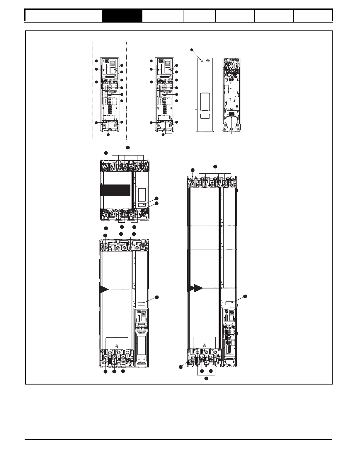
Figure 3-1 Features of the Unidrive M / Unidrive HS size 9 and 10
Mechanical
Installation
Electrical
Installation
Technical data UL Information
Key
1. Rating label 6. Option module slot 3 11. NV media card slot 16. DC bus -
2. Identification label 7. Relay connections 12. Keypad connection 17. Motor connections
3. Status LED 8. Position feedback connections 13. AC supply connections 18. Braking terminal
4. Option module slot 1 9. Control connections 14. Ground connections
5. Option module slot 2 10. Communications port 15. DC bus +
20 Unidrive M / Unidrive HS Modular Installation Guide
Issue Number: 5
Page 21
Safety information Introduction
14
17
14
15
18
13
2
11E 11 T
14
15
16
15
18
14
11D
2
Master Pod
Output to follower
1
2
3
4
5
6
7
8
9
10
11
12
Follower Pod
Input from Master /
Output to follower
Cover
Base
1
4
3
Standard Pod
1
2
3
4
5
6
7
8
9
10
11
12
Single drive systems Parallel systems
15
16
14
Size 11
Rectifier
15
16
14
15
16
14
3
2
14
13
Figure 3-2 Features of the Unidrive M / Unidrive HS size 11
Product
information
System
configuration
Mechanical
Installation
Electrical
Installation
Technical data UL Information
Key
1. Rating label 6. Option module slot 3 11. NV media card slot 16. DC bus -
2. Identification label 7. Relay connections 12. Keypad connection 17. Motor connections
3. Status LED 8. Position feedback connections 13. AC supply connections 18. Braking terminal
4. Option module slot 1 9. Control connections 14. Ground connections
5. Option module slot 2 10. Communications port 15. DC bus +
Unidrive M / Unidrive HS Modular Installation Guide 21
Issue Number: 5
Page 22
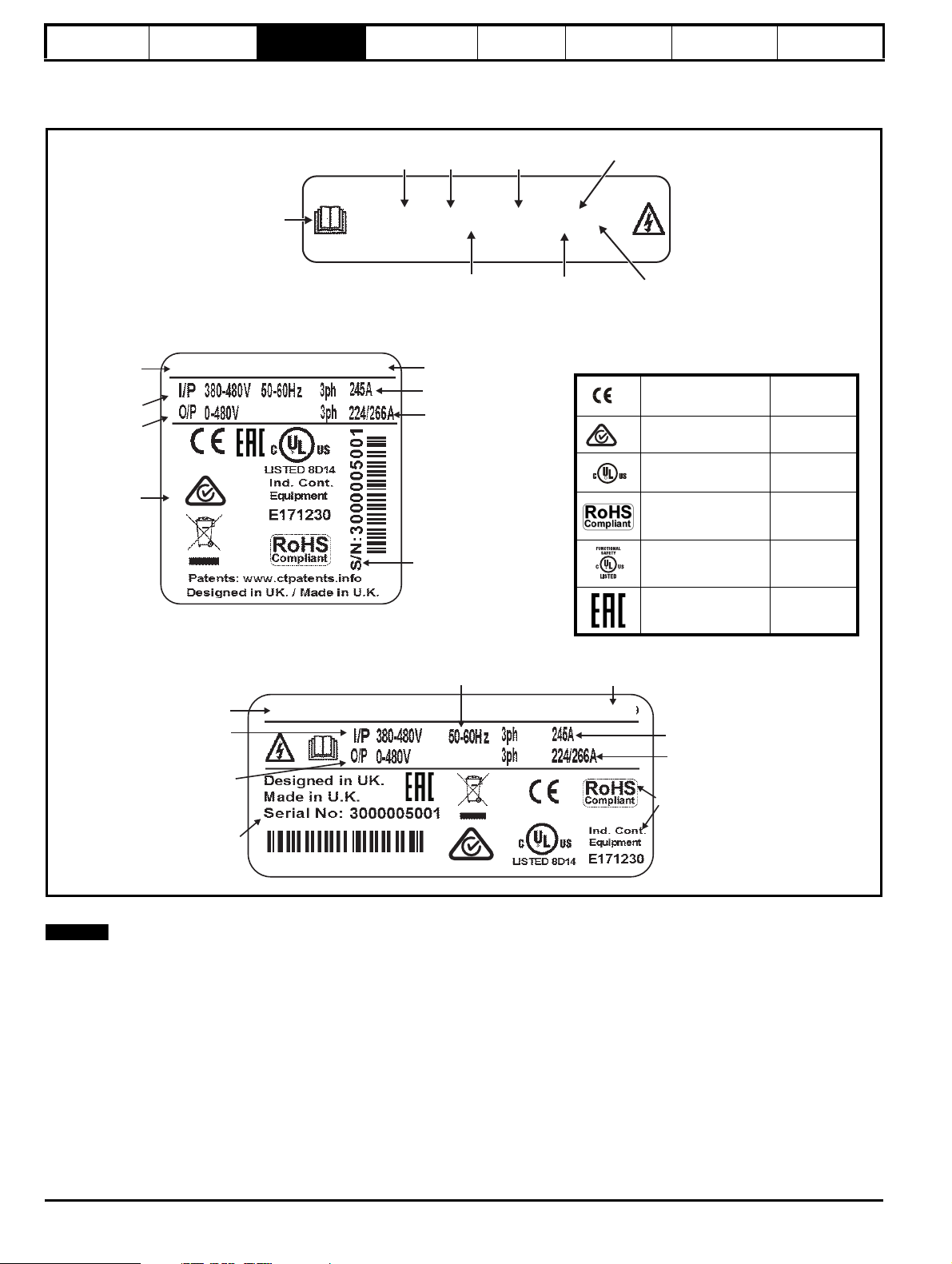
Safety information Introduction
Model
Approvals
Inputphases & input current
Outputphases&Heavy
Duty/Normal Dutyrating
Serial number
Input voltage
Output voltage
Customer anddatecode
M000-094 02240 EUO
110/132kW STDN39
Input frequencyInput frequency
M000-094 02240 EU0
Model
Frame
Voltage
Heavy Duty
current rating
Power
format
No control podfitted
Fan power
supplyfitted
Refer to
User Guide
Normal/Heavy
Duty power rating
Approvals
Inputphases & input current
Outputphases&Heavy
Duty/Normal Dutyrating
Serial number
Input voltage
Output voltage
Customer anddatecode
110/132kW STDN39
Large Label
CE approval Europe
RCM regulatory
compliance mark
Australia
UL / cUL approval
USA &
Canada
RoHS compliant Europe
Functional safety
USA &
Canada
Eurasian conformity Eurasia
R
Key to approvals
NOTE
Product
information
3.3 Nameplate description
Figure 3-3 illustrates typical nameplate and rating labels.
Figure 3-3 Typical drive rating labels
System
configuration
Mechanical
Installation
Electrical
Installation
Technical data UL Information
Refer to Figure 2-13 Drive model number on page 15 for further information relating to the labels.
Date code format
The date code is split into two sections: a letter followed by a number. The letter indicates the year, and the number indicates the week number (within
the year) in which the drive was built. The letters go in alphabetical order, starting with A in 1991 (B in 1992, C in 1993 etc).
Example:
A date code of W28 would correspond to week 28 of year 2013.
22 Unidrive M / Unidrive HS Modular Installation Guide
Issue Number: 5
Page 23
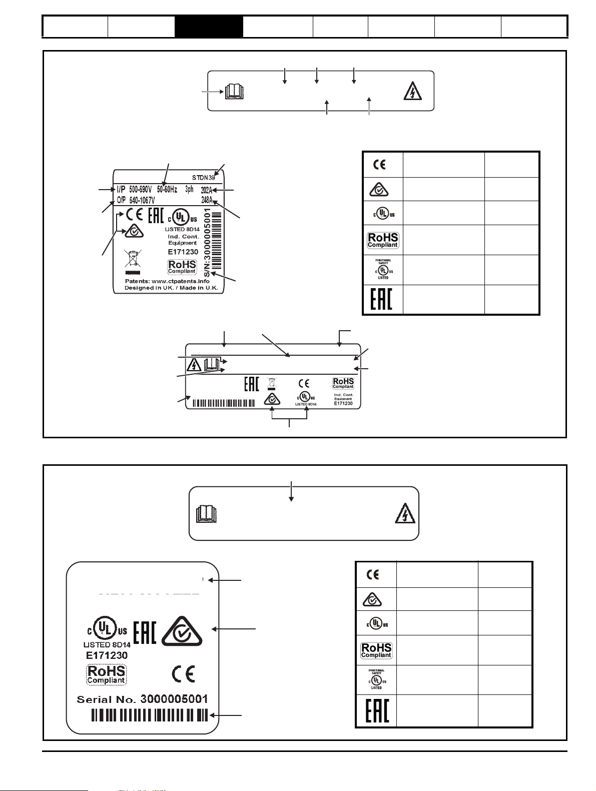
Safety information Introduction
Approvals
Input voltage
Output
voltage
Customer and
datecode
Serial
number
Input
frequency
No.of phases &
Typical input current for
Normal Dutyrating
Output current
RECT-106 02480A STDN39
I/P 500-690V 50-60Hz 3ph 202A
O/P 640-1067V247A
Designed in UK
Made in U.K.
Serial No: 3000005001
Input current
Output current
Model
Input
frequency
Customer and
datecode
Approvals
Serial
number
Output
voltage
Input
voltage
Refer to
User Guide
Model
Frame
size
Voltage
Current rating
Rectifier format
RECT-106 02480A
Key to approvals
CE approval Europe
RCM regulatory
compliance mark
Australia
UL / cUL approval
USA &
Canada
RoHS compliant Europe
Functional safety
USA &
Canada
Eurasia conformity Eurasia
R
M700-MASTER
STDN39 Customer anddatecode
Approvals
Serial numbers
M700-MASTER
Model
Key to approvals
CE approval Europe
RCM regulatory
compliance mark
Australia
UL / cUL approval
USA &
Canada
RoHS compliant Europe
Functional safety
USA &
Canada
Eurasian conformity Eurasia
R
information
Figure 3-4 Typical rectifier rating labels
Product
System
configuration
Mechanical
Installation
Electrical
Installation
Technical data UL Information
Refer to Figure 2-12 Rectifier model number on page 15 for further information relating to the labels.
Figure 3-5 Typical master pod rating labels
Unidrive M / Unidrive HS Modular Installation Guide 23
Issue Number: 5
Page 24
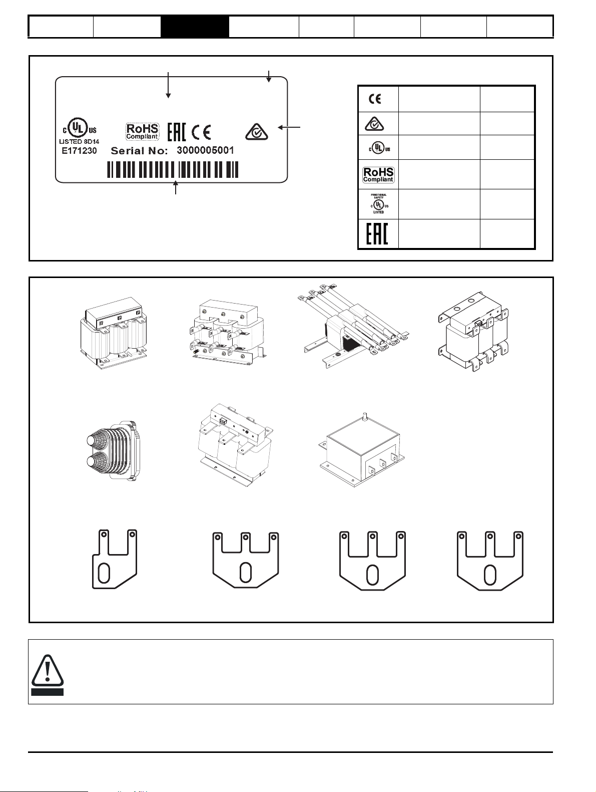
Safety information Introduction
Model
Serial number
Customer anddatecode
M000-FOLLOWER
STDN39
Approvals
Key to approvals
CE approval Europe
RCM regulatory
compliance mark
Australia
UL / cUL approval
USA &
Canada
RoHS compliant Europe
Functional safety
USA &
Canada
Eurasian conformity Eurasia
R
Size 9 and 10 single input line
reactor (INLX0X)
Size 9 and 10 dual output
sharing chokes (OTLX1X) for
parallel module drives
Size 9 and 10 single output
sharing choke (OTLX0X) for
parallel module drives
Size 11 single output sharing
choke (OTLX0X) for parallel
module drives.
EMC filter
Size 11 single input line
reactor (INLX0X)
Finger-guard
grommet double entry
kit 3470-0107 x 8
Size 11D Lifting tool
7778-0031
Size 9E/D/T, 10E/D/T and
size 10 Rectifier Lifting tool
7778-0016
Size 11E/T and size 11
single/twin Rectifier Lifting tool
7778-0030
*
Size 9A Lifting tool
7778-0045
CAUTION
Product
information
System
configuration
Figure 3-6 Typical follower pod rating label
Figure 3-7 Options available for Unidrive M/HS modular drives
Mechanical
Installation
Electrical
Installation
Technical data UL Information
* Limit drive output current to rating of dual output sharing choke.
A separate input line reactor of at least the value shown in Table 6-2 on page 93 must be used with all modular drives other than size 9A
(which has an internal line reactor). Failure to provide sufficient reactance could damage or reduce the service life of the rectifier or inverter.
24 Unidrive M / Unidrive HS Modular Installation Guide
Issue Number: 5
Page 25
Safety information Introduction
6612
NOTE
Product
information
System
configuration
Mechanical
Installation
Electrical
Installation
Technical data UL Information
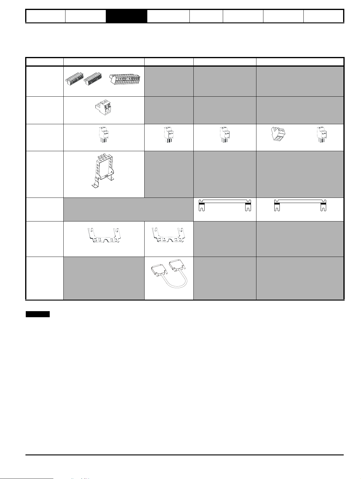
3.4 Supplied items
The drive/rectifier/pod is supplied with a safety information booklet, the Certificate of Quality and an accessory kit box including the items shown in
Table 3-7 (frame 9 and 10), and Table 3-8 (frame 11).
Table 3-7 Parts supplied with the size 9A/E/T, 10E/D
Description Standard / Master Pod Follower Pod Size 10 rectifier Size 9 and 10 inverter
Control
connections
x 1 x 1 x 1
Relay
connector
x 1
24 V power
supply
x 1 x 1 x 1 x1 x1
Grounding
bracket
Surface
mounting
bracket
Paralleling
cable
management
bracket
Paralleling
cable (2m)*
* A two meter paralleling cable is supplied with each follower pod, 1m, 2m and 5m cables are also available separately. Please see
section 4.1.2 Paralleling cable on page 38 for further details.
x 1
x 2 x 2
x 1 x 1
x 1
Unidrive M / Unidrive HS Modular Installation Guide 25
Issue Number: 5
Page 26
Safety information Introduction
6612
6612
NOTE
Product
information
System
configuration
Mechanical
Installation
Electrical
Installation
Technical data UL Information
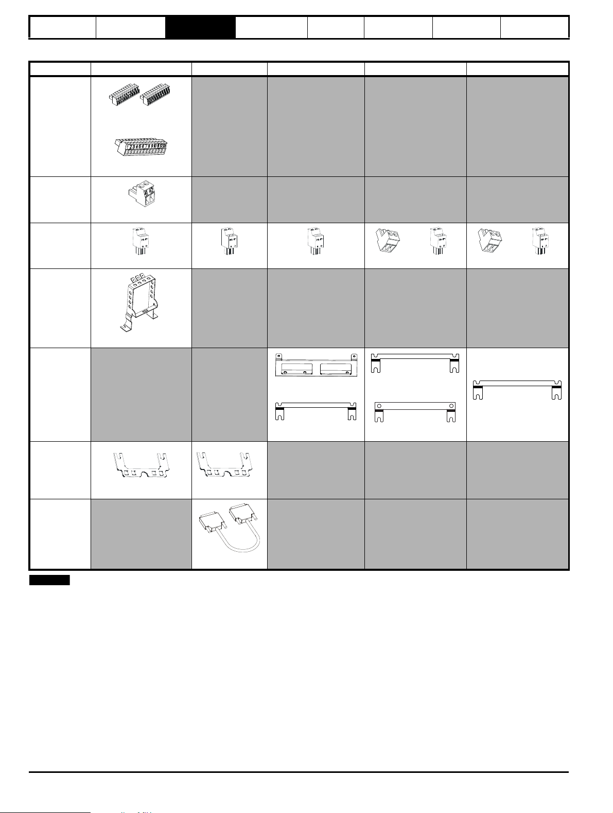
Table 3-8 Parts supplied with the size 11E/ D/T
Description Standard / Master Pod Follower Pod Size 11 rectifier Size 11E Size 11D
Control
connections
Relay
connector
24 V power
supply
Grounding
bracket
Surface
mounting
bracket
x 1 x 1
x 1
x 1
x 2 x 1 x 1 x1 x1 x1 x1
x 1
x 1
x 2
Paralleling
cable
management
bracket
Paralleling
cable (2m)
* A two meter paralleling cable is supplied with each follower pod, 1m, 2m and 5m cables are also available separately. Please see
section 4.1.2 Paralleling cable on page 38 for further details.
x 1 x 1
x 1
x 1
x 1
x 2
26 Unidrive M / Unidrive HS Modular Installation Guide
Issue Number: 5
Page 27
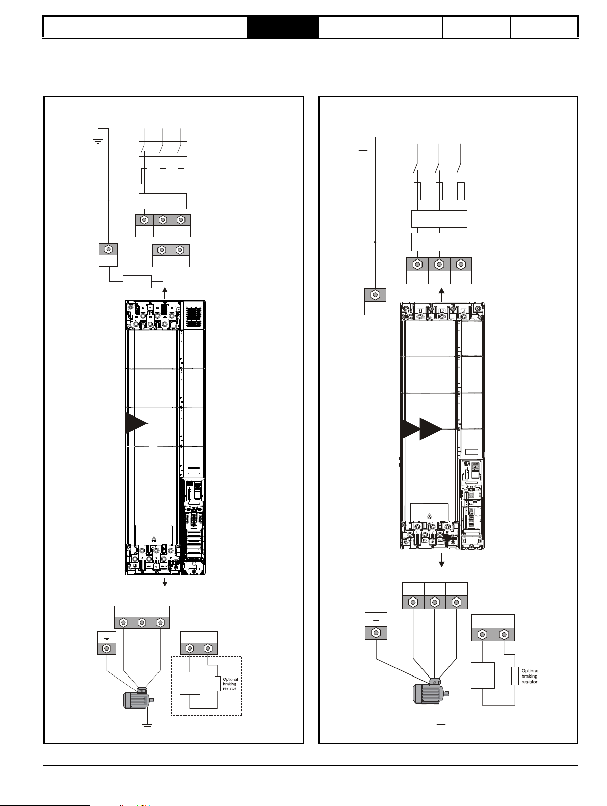
Input connections
Mains
Supply
L1 L2
Optional
EMC filter
Fuses
L3
L1 L2 L3
PE
Supply
ground
+DC -DC
U V W
Motor
Optional ground
connection
+DC BR
Thermal
overload
protection
device
Output connections
Internal EMC
filter
9A
Input connections
Mains
Supply
L1 L2
Line reactor
Optional
EMC filter
Fuses
L3
L1 L2
L3
PE
Supply
ground
9E
10E
UVW
Motor
Optional ground
connection
Output connections
+DC
BR
Thermal
overload
protection
device
Safety information Introduction Product information
System
configuration
Mechanical
Installation
4 System configuration
This chapter describes the various Unidrive M / Unidrive HS size 9, 10 and 11 system configurations.
Figure 4-1 Layout for a Unidrive M / Unidrive HS size 9A module
operating on a 3-phase AC supply
Figure 4-2 Layout for a Unidrive M / Unidrive HS size 9E or 10E
module operating on a 3-phase AC supply
Electrical
Installation
Technical data UL Information
Unidrive M / Unidrive HS Modular Installation Guide 27
Issue Number: 5
Page 28
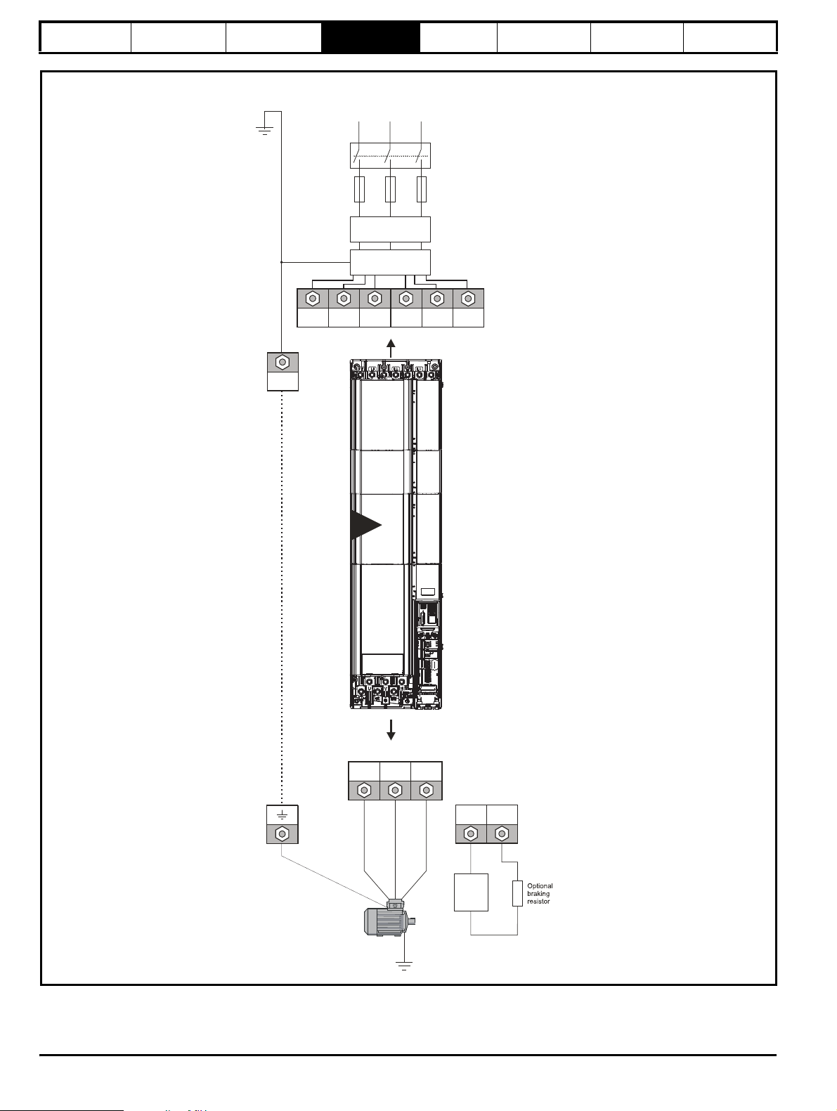
Safety information Introduction Product information
Supply connections
Mains
Supply
L1 L2
Linereactor
Optional
EMC filter
Fuses
L3
Supply
ground
U V W
Motor
Optional ground
connection
+DC BR
Thermal
overload
protection
device
Motor connections
PE
14
11E
L1 L1 L2
L2
L3
L3
*
System
configuration
Mechanical
Installation
Electrical
Installation
Figure 4-3 Layout for a Unidrive M / Unidrive HS size 11E module operating on a 3-phase AC supply
Technical data UL Information
* Connect to either terminal.
28 Unidrive M / Unidrive HS Modular Installation Guide
Issue Number: 5
Page 29
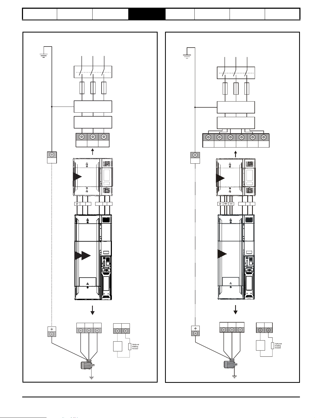
PE
Input connections
Mains
Supply
L1 L2
Line reactor
Optional EMC filter
Fuses
L3
Supply
ground
U V W
Motor
Optional ground
connection
Output connections
L1 L2 L3
+DC BR
Thermal
overload
protection
device
+DC
-DC
24 V
0 V
Comms
9D 10D
10
PE
Input connections
Mains
Supply
L1 L2
Line reactor
Optional EMC filter
Fuses
L3
Supply
ground
U V W
Motor
Optional ground
connection
Output connections
+DC BR
Thermal
overload
protection
device
24 V
0 V
Comms
11D
11
L1 L1 L2 L2 L3 L3
*
Safety information Introduction Product information
System
configuration
Figure 4-4 Layout for a Unidrive M / Unidrive HS size 9D and 10D
module operating on a 3-phase supply
Mechanical
Installation
Electrical
Installation
Technical data UL Information
Figure 4-5 Layout for a Unidrive M / Unidrive HS size 11D
operating on a 3-phase supply
* Connect to either terminal.
Unidrive M / Unidrive HS Modular Installation Guide 29
Issue Number: 5
Page 30
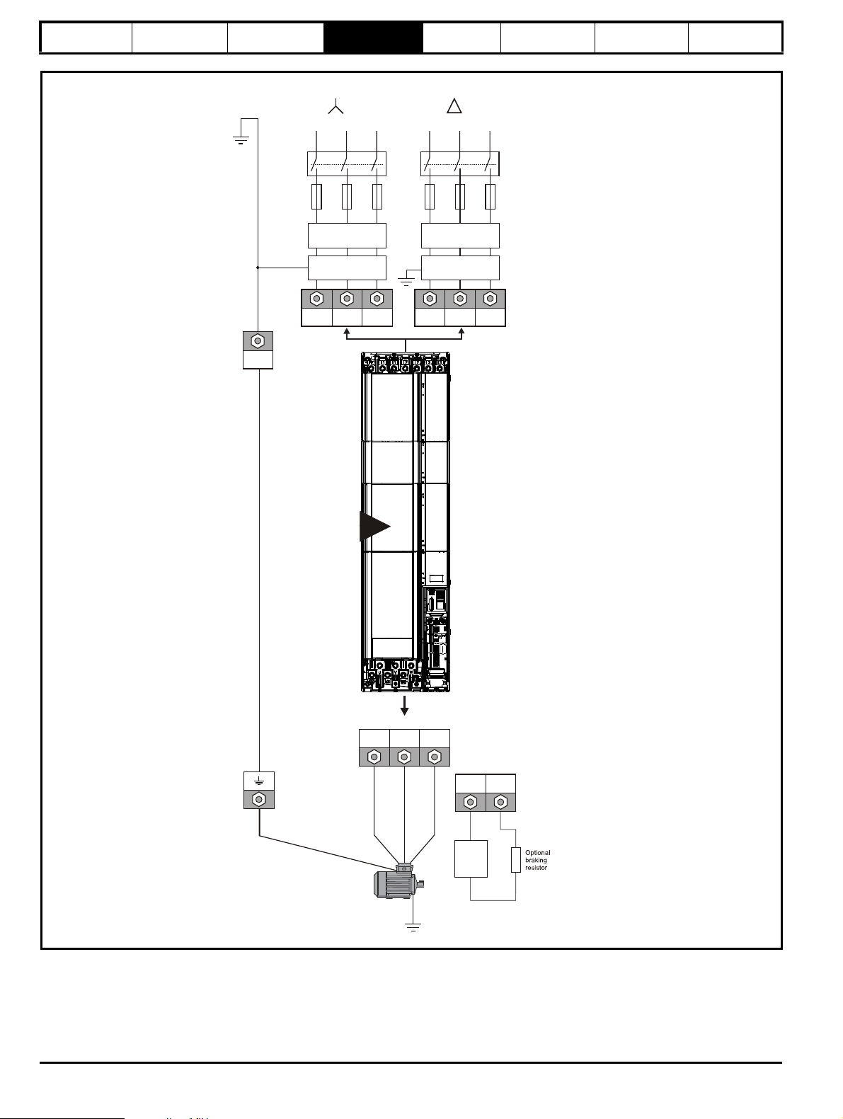
Safety information Introduction Product information
Input connections
Mains
Supply
Mains
Supply
L1 L2
Line reactor*
Optional
EMC filter
Fuses
L3
L1 L2 L3
PE
Supply
ground
U V W
Motor
Optional ground
connection
Output connections
+DC BR
Thermal
overload
protection
device
L1 L2
Line reactor*
Optional
EMC filter
Fuses
L3
L1 L2 L3
11T
Rear row
of terminals
Front row
of terminals
System
configuration
Mechanical
Installation
Electrical
Installation
Figure 4-6 Layout for a Unidrive M / Unidrive HS size 11T supplied from a 12 pulse phase shifted AC supply
Technical data UL Information
* INL chokes may be omitted if:
1. The transformer is dedicated to the drive i.e. not shared with other equipment.
2. The transformer has reactances from primary to secondary and between secondaries of at least 4 % based on the drive rating. This represents a
fully wound transformer with loosely coupled secondaries whose rating (kVA) does not match the drive rating.
30 Unidrive M / Unidrive HS Modular Installation Guide
Issue Number: 5
Page 31

L3
L2
L1
Fuses Fuses
Master Follower
OTLXXX
sharing
chokes
UVW UVW
Paralleling cable
OTLXXX
sharing
chokes
9A
9A
Safety information Introduction Product information
Figure 4-7 Layout for two Unidrive M / Unidrive HS size 9A modules operating on a 6 pulse 3-phase AC supply
System
configuration
Mechanical
Installation
Electrical
Installation
Technical data UL Information
Unidrive M / Unidrive HS Modular Installation Guide 31
Issue Number: 5
Page 32

Safety information Introduction Product information
L3
L2
L1
Fuses
Fuses
Master Follower
OTLXXX
sharing
chokes
UVW UVW
Paralleling cable
OTLXXX
sharing
chokes
INLXXX
Line reactor
INLXXX
Line reactor
9E
11E
10E
9E
11E
10E
10E
Figure 4-8 Layout for two Unidrive M / Unidrive HS size 9E, 10E or 11E modules operating on a 6 pulse 3-phase AC supply
System
configuration
Mechanical
Installation
Electrical
Installation
Technical data UL Information
32 Unidrive M / Unidrive HS Modular Installation Guide
Issue Number: 5
Page 33

L3
L2
L1
MasterMaster FollowerFollower
INLXXX
Line reactor
INLXXX
Line reactor
CommsComms
24 V24 V
0 V0 V
FusesFuses
OTLXXX
sharing
chokes
U V W U V W
OTLXXX
sharing
Parallelling cable
chokes
9D9D
11
+DC
-DC
+DC
-DC
10D10D 11D 9D9D 10D10D 11D
111010 11 11 111010 11
Safety information Introduction Product information
System
configuration
Mechanical
Installation
Electrical
Installation
Technical data UL Information
Figure 4-9 Layout for two or more Unidrive M / Unidrive HS size 9D, 10D or 11D with single size 10 or 11 rectifiers operating on a 6 pulse
3-phase AC supply
Unidrive M / Unidrive HS Modular Installation Guide 33
Issue Number: 5
Page 34

Safety information Introduction Product information
MasterMaster FollowerFollower
INLXXX
Line reactor*
INLXXX
Line reactor*
FusesFuses
OTLXXX
sharing
chokes
U V W U V W
OTLXXX
sharing
Parallelling cable
chokes
L3
L2
L1
L3
L2
L1
11D 11D
11
11
System
configuration
Mechanical
Installation
Electrical
Installation
Technical data UL Information
Figure 4-10 Layout for two Unidrive M / Unidrive HS size 11D with single size 11 rectifiers operating on a 12 pulse phase shifted AC supply
* INL chokes may be omitted if:
1. The transformer is dedicated to the drive i.e. not shared with other equipment.
2. The transformer has reactances from primary to secondary and between secondaries of at least 4% based on the drive rating. This represents a
fully-wound transformer with loosely-coupled secondaries whose rating (kVA) does not much exceed the drive rating.
34 Unidrive M / Unidrive HS Modular Installation Guide
Issue Number: 5
Page 35

2 x INLXXX
Line reactor
Comms
24 V
0 V
Fuses
Fuses
OTLXXX
sharing
chokes
U V W
OTLXXX
sharing
Parallelling cable
chokes
9D9D 10D10D
9D9D 10D10D
L3
L2
L1
L3
L2
L1
+DC
-DC
11
Safety information Introduction Product information
System
configuration
Mechanical
Installation
Electrical
Installation
Technical data UL Information
Figure 4-11 Layout for two Unidrive M / Unidrive HS size 9D/10D with twin size 11 rectifier on a 6 pulse 3-phase supply
Unidrive M / Unidrive HS Modular Installation Guide 35
Issue Number: 5
Page 36

Safety information Introduction Product information
2 x INLXXX
Line reactor*
Fuses
Fuses
L3
L2
L1
L3
L2
L1
OTLXXX
sharing
chokes
U V W
OTLXXX
sharing
Parallelling cable
chokes
9D9D 10D10D
9D9D 10D10D
11
+DC
-DC
U V W
System
configuration
Mechanical
Installation
Electrical
Installation
Technical data UL Information
Figure 4-12 Layout for two Unidrive M / Unidrive HS size 9D/10D with twin size 11 rectifier operating on a 12 pulse phase shifted AC supply
* INL chokes may be omitted if:
1. The transformer is dedicated to the drive i.e. not shared with other equipment.
2. The transformer has reactances from primary to secondary and between secondaries of at least 4% based on the drive rating. This represents a
fully-wound transformer with loosely-coupled secondaries whose rating (kVA) does not much exceed the drive rating.
36 Unidrive M / Unidrive HS Modular Installation Guide
Issue Number: 5
Page 37

Safety information Introduction Product information
(2)
(2)
(2)
AC fuses not adequate
DC fuses are required
AC fuses are adequate
(3)
(3)
(3) (3)
(2)
(3)
(2)
(3)
NOTE
System
configuration
Mechanical
Installation
Electrical
Installation
Technical data UL Information
4.1.1 DC fusing
The Unidrive M/HS modular system has undergone safety testing and proving when using the specified AC input fuses, including the case where the
size 11 twin rectifier is used to supply two D type modules. A fault in any module is cleared by the AC input fuses.
If more rectifiers or inverters are connected to the DC bus then the prospective fault current and the energy delivered before a fault is cleared are
increased because of the multiple sources and the increased stored energy in the inverter capacitors. It then becomes necessary to provide fuses in
the DC bus. This is illustrated in Figure 4-13.
Figure 4-13 Fault current contributions
As shown in Figure 4-14 when DC fuses are required they must be placed in the rectifier output circuits as well as the inverter inputs, since they are
also exposed to the total fault-current infeed. For the size 11 twin rectifier, only one fuse pair is needed for the complete module.
The only exception to this rule is where the rectifier input fuses are reduced in rating so that the total i2t let-through for all of the phases is no greater
than that for the standard recommended fuses for the 6-pulse arrangement. This will be the case for some of the lower-power multi-pulse
arrangements. This needs to be verified on a case-by-case basis.
All DC fuses are in pairs, i.e. one in each pole, to provide protection against earth faults.
Figure 4-14 12-pulse system using twin rectifiers and 6-phase AC distribution with odd number of inverter modules
Please see Table 6-15 DC fuse and cable ratings for Unidrive M / HS size 9, 10 and 11 inverters on page 102 for DC fuse ratings.
Unidrive M / Unidrive HS Modular Installation Guide 37
Issue Number: 5
Page 38

Safety information Introduction Product information
System
configuration
Mechanical
Installation
Electrical
Installation
Technical data UL Information
4.1.2 Paralleling cable
Part numbers
A single two meter paralleling cable is supplied with each follower pod. 1 m, 2 m and 5 m cables are also available separately (see Table 4-1 for part
numbers)
Table 4-1 Paralleling cable part numbers
Description Part number
1 m paralleling cable 3471-9842
2 m paralleling cable 3471-0013
5 m paralleling cable 3471-6850
Maximum lengths
Individual links between modules should be nominally 2 m in length however a maximum of two 5 m lengths can be used in a parallel system. The
maximum combined paralleling cable length can not exceed 40 m.
38 Unidrive M / Unidrive HS Modular Installation Guide
Issue Number: 5
Page 39

Safety information Introduction Product information
WARNING
WARNING
WARNING
WARNING
NOTE
Drive
5
o
5
o
Notless
tha n 2X
Ba ffle plate s (m ay be
aboveor below bottom
ofenclosure)
X
Bottom of fire
enclosure
Not less
than 2
times ‘X’
Baffle plates (may be above or
below bottom of enclosure)
Bottom of fire enclosure
X
System
configuration
5 Mechanical Installation
This chapter describes all the mechanical details required to install the
drive. The drive is intended to be installed in an enclosure. Key features
of this chapter include:
• Surface and through-panel mounting
• Remote mounting of control master pod
• Enclosure sizing and layout
• Terminal location and torque settings
5.1 Safety information
Follow the instructions
The mechanical and electrical installation instructions must
be adhered to. Any questions or doubt should be referred to
the supplier of the equipment. It is the responsibility of the
owner or user to ensure that the installation of the drive and
any external option unit, and the way in which they are
operated and maintained, comply with the requirements of
the Health and Safety at Work Act in the United Kingdom or
applicable legislation and regulations and codes of practice in
the country in which the equipment is used.
Competence of the installer
The drive must be installed by professional assemblers who
are familiar with the requirements for safety and EMC. The
assembler is responsible for ensuring that the end product or
system complies with all the relevant laws in the country
where it is to be used.
Many of the drives in this product range weigh in excess of 15
kg (33 lb). Use appropriate safeguards when lifting these
models.
Mechanical
Installation
Electrical
Installation
Technical data UL Information
5.2.3 Cooling
The heat produced by the drive must be removed without its specified
operating temperature being exceeded. Note that a sealed enclosure
gives much reduced cooling compared with a ventilated one, and may
need to be larger and/or use internal air circulating fans.
For further information, please refer to section 5.6.4 Enclosure sizing on
page 64.
5.2.4 Electrical safety
The installation must be safe under normal and fault conditions.
Electrical installation instructions are given in Chapter 6 Electrical
Installation on page 85.
5.2.5 Fire protection
The drive enclosure is not classified as a fire enclosure. A separate fire
enclosure must be provided.
For installation in the USA, a NEMA 12 enclosure is suitable.
For installation outside the USA, the following (based on IEC 62109-1,
standard for PV inverters) is recommended.
Enclosure can be metal and/or polymeric, polymer must meet
requirements which can be summarized for larger enclosures as using
materials meeting at least UL 94 class 5VB at the point of minimum
thickness.
Air filter assemblies to be at least class V-2.
The location and size of the bottom shall cover the area shown in Figure
5-1. Any part of the side which is within the area traced out by the 5°
angle is also considered to be part of the bottom of the fire enclosure.
Figure 5-1 Fire enclosure bottom layout
Enclosure
The drive is intended to be mounted in an enclosure which
prevents access except by trained and authorized
personnel, and which prevents the ingress of contamination.
It is designed for use in an environment classified as
pollution degree 2 in accordance with IEC 60664-1. This
means that only dry, non-conducting contamination is
acceptable.
5.2 Planning the installation
The following considerations must be made when planning the installation:
5.2.1 Access
Access must be restricted to authorized personnel only. Safety
regulations which apply at the place of use must be complied with. The
IP (Ingress Protection) rating of the drive is installation dependent.
5.2.2 Environmental protection
The drive must be protected from:
• moisture, including dripping water or spraying water and
condensation. An anti-condensation heater may be required, which
must be switched off when the drive is running.
• contamination with electrically conductive material
• contamination with any form of dust which may restrict the fan, or
impair airflow over various components
• temperature beyond the specified operating and storage ranges
• corrosive gasses
During installation it is recommended that the vents on the drive are
covered to prevent debris (e.g. wire off-cuts) from entering the drive.
The bottom, including the part of the side considered to be part of the
bottom, must be designed to prevent escape of burning material - either
by having no openings or by having a baffle construction. This means
that openings for cables etc. must be sealed with materials meeting the
5VB requirement, or else have a baffle above. See Figure 5-2 for
acceptable baffle construction. This does not apply for mounting in an
enclosed electrical operating area (restricted access) with concrete floor.
Figure 5-2 Fire enclosure baffle construction
Unidrive M / Unidrive HS Modular Installation Guide 39
Issue Number: 5
Page 40

Safety information Introduction Product information
WARNING
WARNING
System
configuration
5.2.6 Electromagnetic compatibility
Variable speed drives are powerful electronic circuits which can cause
electromagnetic interference if not installed correctly with careful
attention to the layout of the wiring.
Some simple routine precautions can prevent disturbance to typical
industrial control equipment.
If it is necessary to meet strict emission limits, or if it is known that
electromagnetically sensitive equipment is located nearby, then full
precautions must be observed. In-built into the drive, is an internal EMC
filter, which reduces emissions under certain conditions. If these
conditions are exceeded, then the use of an external EMC filter may be
required at the drive inputs, which must be located very close to the
drives. Space must be made available for the filters and allowance made
for carefully segregated wiring. Both levels of precautions are covered in
section 6.13 EMC (Electromagnetic compatibility) on page 108.
5.2.7 Hazardous areas
The drive must not be located in a classified hazardous area unless it is
installed in an approved enclosure and the installation is certified.
5.3 Terminal cover removal
Isolation device
The AC supply must be disconnected from the drive using an
approved isolation device before any cover is removed from
the drive or before any servicing work is performed.
Mechanical
Installation
Electrical
Installation
Technical data UL Information
Stored charge
The drive contains capacitors that remain charged to a
potentially lethal voltage after the AC supply has been
disconnected. If the drive has been energized, the AC
supply must be isolated at least ten minutes before work
may continue.
Normally, the capacitors are discharged by an internal
resistor. Under certain, unusual fault conditions, it is possible
that the capacitors may fail to discharge, or be prevented
from being discharged by a voltage applied to the output
terminals. If the drive has failed in a manner that causes the
display to go blank immediately, it is possible the capacitors
will not be discharged. In this case, consult Control
Techniques or their authorized distributor.
5.3.1 Removing the terminal covers
Unidrive M / Unidrive HS size 9/10/11 D and E are installed with three
terminal covers: Control, input and output terminal covers.
Unidrive M / Unidrive HS rectifiers are installed with two terminal covers:
Input and output terminal covers. The terminal covers must be removed
to gain access to all the terminals.
40 Unidrive M / Unidrive HS Modular Installation Guide
Issue Number: 5
Page 41

Safety information Introduction Product information
9A 9E 9T10E10T 11E 11T
Output
Control
Output
Input
Input
Input
9D10D11D
Output
Control
Rectifier
Figure 5-3 Location and identification of terminal covers
System
configuration
Mechanical
Installation
Electrical
Installation
Technical data UL Information
Unidrive M / Unidrive HS Modular Installation Guide 41
Issue Number: 5
Page 42

Safety information Introduction Product information
Pozi Pz2
T25Torx
Pozi Pz2
System
configuration
Mechanical
Installation
Figure 5-4 Removing the terminal covers on Unidrive M / Unidrive HS size 9, 10 and 11
Electrical
Installation
Technical data UL Information
To remove a terminal cover, undo the screw and lift the terminal cover off as shown.
When replacing the terminal covers the screws should be tightened with a maximum torque of 1 N m (0.7 lb ft).
Figure 5-5 Removing the Unidrive M / Unidrive HS size 10 and 11 rectifier terminal covers
To remove a terminal cover, undo the screw and lift the terminal cover off as shown.
When replacing the terminal covers the screws should be tightened with a maximum torque of 1 N m (0.7 lb ft).
42 Unidrive M / Unidrive HS Modular Installation Guide
Issue Number: 5
Page 43

Safety information Introduction Product information
WARNING
System
configuration
Mechanical
Installation
5.3.2 Removing the finger-guard and DC terminal cover break-outs
Figure 5-6 Removing the finger-guard break-outs
Electrical
Installation
Technical data UL Information
All sizes:
Place the finger-guard on a flat solid surface and hit relevant break-outs with hammer as shown (1). Pliers can be used to remove the breakouts,
grasp the relevant break-out with pliers and twist it as shown (3). Continue until all the required break-outs have been removed (2). Remove any flash
/ sharp edges once the break-outs have been removed.
The grommets must be installed to ensure ingress protection to IP20 and to avoid the risk of fire in the event of a major internal failure.
Grommet kits are available for size 9, 10 and 11 power terminal finger guards.
Table 5-1 Grommet kits for power terminal finger guards
Drive size Quantity of kits Part number Picture
Size 9 and 10 - Kit of 8 x double entry
grommets
Size 11 - Kit of 8 x double entry
grommets
1 3470-0107
2 3470-0107
Unidrive M / Unidrive HS Modular Installation Guide 43
Issue Number: 5
Page 44

Safety information Introduction Product information
2
2
1
2
2
11
NOTE
System
configuration
5.4 Mounting of the control master/ follower/standard pod
For control master/follower pod paralleling connections, refer to Figure
5-9 Parallel control connections on page 45.
Figure 5-7 Mounting the control master or standard pod on the
drive
Mechanical
Installation
Electrical
Installation
Technical data UL Information
Figure 5-8 Mounting the control follower pod on the drive
1. In order to expose the control master/follower mounting holes, the
terminal covers need to be removed. This is done by undoing the
terminal cover screw highlighted and then removing the two plastic
covers.
2. Care must be taken when installing master control pod. Line up the
connector on the back of the master control pod with the respective
connector on the power module. Use the 3 x M5 screws to mount
the control master pod to the drive in the position shown.
The terminal covers can then be re-installed.
1. In order to expose the mounting holes, remove the control follower
pod cover. This is done by undoing the screw highlighted and
removing the cover.
2. Care must be taken when installing follower control pod. Line up the
connector on the back of the follower control pod with the respective
connector on the power module. Use the 3 x M5 screws to mount
the control master pod to the drive in the position shown.
The cover can then be re-installed.
The control master pod can also be remotely mounted and connected to
the first follower with a parallel cable, see Figure 5-19 Control master
pod dimensions and remote surface mounting diagram on page 53 for
mounting information.
44 Unidrive M / Unidrive HS Modular Installation Guide
Issue Number: 5
Page 45

Safety information Introduction Product information
Parallelingcable*
Input from
master
to follower
Outputto
next
follower
Control master pod
Output from
master to
follower
Control
follower pod
NOTE
Figure 5-9 Parallel control connections
System
configuration
Mechanical
Installation
Electrical
Installation
Technical data UL Information
*Only supplied with follower drive.
N
The parallel cable should be routed according to the rules shown in Figure 6-29 Sensitive signal circuit clearance on page 113 for the control cable.
The screw locks on the parallel cable must be fully tightened.
The orientation of the parallel cable ports on Unidrive M / Unidrive HS are opposite to Unidrive SP.
Unidrive M / Unidrive HS Modular Installation Guide 45
Issue Number: 5
Page 46

Safety information Introduction Product information
Figure 5-10 Installation of parallel cable management bracket
System
configuration
Mechanical
Installation
Electrical
Installation
Technical data UL Information
Loosen the ground connection nuts and slide the cable management
bracket in the direction shown. Once in place, the ground connection
nuts should be tightened with a maximum torque of 2 N m (1.47 Ib ft).
46 Unidrive M / Unidrive HS Modular Installation Guide
Issue Number: 5
Page 47

Safety information Introduction Product information
WAR NING
WARNING
285 mm (11.22 in)
310 mm (12.20 in)
1108 mm (43.61 in)
290 mm (11.42 in)
1049 mm (41.31 in)
259 mm (10.18 in)
26 mm
(1.01 in)
9mm
(0.35 in)
∅
9.0 mm (0.35 in)
x 4 holes
1090 mm (42.90 in)
System
configuration
Mechanical
Installation
Electrical
Installation
Technical data UL Information
5.5 Dimensions and mounting methods
Unidrive M / Unidrive HS size 9, 10, 11 and rectifier can be either surface or through-panel mounted using the appropriate brackets.
Surface mounting is where the drive is simply secured to the enclosure wall/backplate.
Through-panel mounting is where the drive is secured with the heatsink protruding through the enclosure panel to the external environment. This has
the effect of reducing the temperature within the enclosure.
The following drawings show the dimensions of the drive and mounting holes for each method to allow a back plate to be prepared.
If the drive has been used at high load levels for a period of time, the heatsink can reach temperatures in excess of 70°C (158°F). Human
contact with the heatsink should be prevented.
Many of the drives in this product range weigh in excess of 15 kg (33 lb). Use appropriate safeguards when lifting these models. Use the
appropriate lifting bracket as shown in Figure 3-7 Options available for Unidrive M/HS modular drives on page 24.
5.5.1 Surface mounting
Figure 5-11 Surface mounting the Unidrive M / Unidrive HS size 9A
Unidrive M / Unidrive HS Modular Installation Guide 47
Issue Number: 5
Page 48

Safety information Introduction Product information
259 mm (10.20 in)
Æ9.0mm(0.35 in)
x4holes
1051 mm (4
1.38 in)
290 mm (11 .42in)
1010mm(
39.76 in)
310mm(12.21 in)
285 mm (11.22 in)
1069 mm (4
2.09 in)
9mm
(0.35 in)
26mm
(1.02in)
System
configuration
Figure 5-12 Surface mounting the Unidrive M / Unidrive HS size 9E/10E
Mechanical
Installation
Electrical
Installation
Technical data UL Information
48 Unidrive M / Unidrive HS Modular Installation Guide
Issue Number: 5
Page 49

Safety information Introduction Product information
285 mm (11.22 in)285 mm (11 .22 in)
1141 mm (44.9
2 in)
1141 mm (44.92 in)
1100 mm (4
3.31 in)
1100 mm (43.31 in)
259 mm (10.20 in)
Æ9.0 mm (0.35 in)
x 4 holes
1141 mm (44.9
2 in)
9 mm
(0.35 in)
26 mm
(1.02 in)
310 mm (12.20 in)310 mm (12.20 in)
1159 mm (45.6
3 in)
1159 mm (45.63 in)
259 mm (10.20 in)259 mm (10.20 in)
290 mm (11.42 in)
System
configuration
Figure 5-13 Surface mounting the Unidrive M / Unidrive HS size 9T/10T
Mechanical
Installation
Electrical
Installation
Technical data UL Information
Unidrive M / Unidrive HS Modular Installation Guide 49
Issue Number: 5
Page 50

Safety information Introduction Product information
285 mm (11.22 in)
310 mm (12.21 in)
1242 mm (48.90
in)
313 mm (12.32 in)
1189 mm (46.8
1 in)
259 mm (10.19 in)
26 mm
(1.02 in)
Æ 9mm (0.35 in)
x 4 holes
12 mm
(0.47 in)
1222 mm (48.
1
1 in)
System
configuration
Figure 5-14 Surface mounting the Unidrive M / Unidrive HS size 11E / 11T
Mechanical
Installation
Electrical
Installation
Technical data UL Information
50 Unidrive M / Unidrive HS Modular Installation Guide
Issue Number: 5
Page 51

Safety information Introduction Product information
310mm(12.21 in)
285 mm (11.22 in)
773 mm (30.43in)
714mm(
28.1
1in)
290 mm (11. 42in)
259 mm (10.20 in)
755 mm (
29.72in)
Æ9.0mm(0.35 in)
x4holes
9mm
(0.35 in)
26mm
(1.02in)
313 mm (12.32 in)
310 mm (12.21 in)
285 mm (11.22 in)
863 mm (33.97 in)
804 mm (
31.65 in)
26 mm
(1.02 in)
259 mm (10.19 in)
9 mm
(0.35) in
x 4 holes
845 mm (
33.26 in)
9 mm
(0.35 in)
Æ
System
configuration
Figure 5-15 Surface mounting the Unidrive M / Unidrive HS size 9D/10D
Mechanical
Installation
Electrical
Installation
Technical data UL Information
Figure 5-16 Surface mounting the Unidrive M / Unidrive HS size 11D
Unidrive M / Unidrive HS Modular Installation Guide 51
Issue Number: 5
Page 52

Safety information Introduction Product information
310 mm (12.21 in)
285 mm (11.22 in)
355 mm (
13.98 in)
290 mm (11.42 in)
296 mm (
1
1.65 in)
337 mm (
13.27 in)
259 mm (10.20 in)
Æ 9.0 mm (0.35 in)
x 4 holes
26 mm
(1.02 in)
9 mm
(0.35 in)
290 mm (11.41 in)
310 mm (12.21 in)
285 mm (11.22 in)
405.5 mm (
15.96 in)
386 mm (
15.20 in)
26 mm
(1.02 in)
259 mm
(10.19 in)
9 mm
(0.35 in)
x 4 holes
145.3 mm
(5.72 in)
Æ
380.5mm (
14.98 in)
9 mm
(0.35 in)
49 mm
(1.92 in)
213 mm (8.38 in)
System
configuration
Mechanical
Installation
Figure 5-17 Surface mounting the Unidrive M / Unidrive HS size 10 rectifier
Figure 5-18 Surface mounting the Unidrive M / Unidrive HS size 11 rectifier
Electrical
Installation
Technical data UL Information
52 Unidrive M / Unidrive HS Modular Installation Guide
Issue Number: 5
Page 53

Safety information Introduction Product information
367.5mm
(14.5 in)
346.0mm
(13.7 in)
92.5mm
(3.65 in)
Mounting
holes
60.4mm
(2.40 in)
139mm(5.47 in)
System
configuration
Mechanical
Installation
Figure 5-19 Control master pod dimensions and remote surface mounting diagram
Electrical
Installation
Technical data UL Information
Unidrive M / Unidrive HS Modular Installation Guide 53
Issue Number: 5
Page 54

Safety information Introduction Product information
341 mm (13.42in)
285 mm (11.22 in)
310mm(12.20 in)
1108 mm (4
3.61in)
190 mm (7.48 in)
100 mm
(3.94 in)
1049 mm (4
1.31 in
)
259 mm (10.18 in)
287±1mm(11.3 in)±0.04
328mm(12.90 in)
Æ9.0mm(0.35 in)
x4holes
942 mm (37.08 in)
734mm(
28.89 in)
491 mm (19.32 in)
231 mm (9.09 in)
Æ5.5mm(0.21 in)
x8holes
32 mm
(1.24 in)
211 mm (8.30 in)
471 mm (18.54 in)
714mm(
28.10 in)
923 mm (36.33 in)
1058 mm (4
1.66 in)
System
configuration
Mechanical
Installation
Electrical
Installation
Technical data UL Information
5.5.2 Through-panel mounting
The Through-panel mounting kits are not supplied with the drive and can be purchased separately, using the part numbers shown below:
Table 5-2 Through panel mounting kits
Part number Description
3470-0105 Size 9E/10E
3470-0106 Size 10 rectifier only
3470-0108 Size 9D and 10D inverter only
3470-0119 Size 9A
3470-0127 Size 9T/10T
3470-0126 Size 11E/11T
3470-0130 Size 11D inverter only
3470-0123 Size 11 rectifier only
Figure 5-20 Through-panel mounting the Unidrive M / Unidrive HS size 9A
54 Unidrive M / Unidrive HS Modular Installation Guide
Issue Number: 5
Page 55

Safety information Introduction Product information
n5.5 typ.
8 places
989.8
259 mm (10.20 in)
287±1 mm (11.3±0.04 in)
327mm(12.87 in)
883 mm (34.76 in)
586 mm (
23.07 in)
406 mm (
15.98 in)
231 mm (9.09 in)
Æ9.0mm(0.35 in)
x4holes
Æ5.5mm(0.22 in)
x8holes
1051 mm (4
1.38 in)
863 mm (33.98 in)
566 mm (
22.28 in)
386 mm (
15.20 in)
211 mm (8.31 in)
31 mm
(1.22 in)
190 mm (7.48 in)
99 mm
(3.90 in)
340 mm (13.39 in)
310mm(12.21 in)
285 mm (11.22 in)
1069mm(4
2.09 in)
1010mm(
39.76 in)
System
configuration
Mechanical
Installation
Figure 5-21 Through-panel mounting the Unidrive M / Unidrive HS size 9E/10E
Electrical
Installation
Technical data UL Information
Unidrive M / Unidrive HS Modular Installation Guide 55
Issue Number: 5
Page 56

Safety information Introduction Product information
285 mm (11.22 in)285 mm (11.22 in)
340 mm (13.39 in)340 mm (13.39 in)
1078 mm (4
2.44 in)
1078 mm (42.44 in)
210 mm (8.
27 in)
210 mm (8.27 in)
862 mm (33.94 in)
862 mm (33.94 in)
230 mm (9.05
in)
230 mm (9.05 in)
406 mm (
15.98 in)
406 mm (15.98 in)
586 mm (
23.07 in)
586 mm (23.07 in)
882 mm (34.72 in)
882 mm (34.72 in)
1028 mm (40.47
in)
1028 mm (40.47 in)
327 mm (12.87 in)327 mm (12.87 in)
1159 mm (45.6
3 in)
1159 mm (45.63 in)
310 mm (12.20 in)310 mm (12.20 in)
1100 mm (4
3.31 in)
1100 mm (43.31 in)
190 mm (7.48 in)190 mm (7.48 in)
Æ9.0 mm (0.35 in) x 4 holesÆ9.0 mm (0.35 in) x 4 holes
Æ5.5 mm (0.22 in) x 10 holesÆ5.5 mm (0.22 in) x 10 holes
1141 mm (44.9
2 in)
1141 mm (44.92 in)
386 mm (
15.20 in)
386 mm (15.20 in)
566 mm (
22.28 in)
566 mm (22.28 in)
1008 mm (
39.68 in)
1008 mm (39.68 in)
100 mm
(3.94 in)
100 mm
(3.94 in)
259 mm (10.20 in)259 mm (10.20 in)
287±1 mm (11.3±0.04 in)
System
configuration
Mechanical
Installation
Figure 5-22 Through-panel mounting the Unidrive M / Unidrive HS size 9T/10T
Electrical
Installation
Technical data UL Information
56 Unidrive M / Unidrive HS Modular Installation Guide
Issue Number: 5
Page 57

Safety information Introduction Product information
190 mm (7.48 in)
123 mm
(4.84 in)
1189 mm (46.8
1 in)
259 mm (10.19 in)
287±1 mm (11.3±0.04 in)
327 mm (12.87 in)
Æ 9 mm (0.35 in)
x 4 holes
1231 mm (48.
31 in)
1098 mm (4
3.22 in)
953 mm (37.51 in)
712 mm (28.03 in)
566 mm (
22.28 in)
386 mm (
15.19 in)
211 mm (8.
30 in)
31 mm
(1.22 in)
285 mm (11.22 in)
310 mm (12.21 in)
340 mm (13.38 in)
1249 mm (49.
17 in)
Æ 5.5 mm
(0.21 in)
x 12 holes
1170 mm (46.06 in)
1118 mm (44.01 in)
973 mm (38.30 in)
732 mm (28.81 in)
586 mm (23.07 in)
406 mm (15.98 in)
231 mm (9.09 in)
System
configuration
Mechanical
Installation
Figure 5-23 Through-panel mounting the Unidrive M / Unidrive HS size 11E/11T
Electrical
Installation
Technical data UL Information
Unidrive M / Unidrive HS Modular Installation Guide 57
Issue Number: 5
Page 58

Safety information Introduction Product information
285 mm (11.22 in)
310mm(12.21 in)
340 mm (13.39 in)
773 mm (30.43in)
190 mm (7.48 in)
99 mm (3.90 in)
714mm(
28.11 in)
693.7
231 mm (9.09 in)
406 mm (
15.98 in)
586 mm (
23.07 in)
30mm
(1.18 in)
211 mm (8.31 in)
386 mm (
15.20 in)
566 mm (
22.28 in)
755 mm (
29.72in)
Æ5.5mm(0.22 in)
x6holes
Æ9mm(0.22 in)
x4holes
259 mm (10.20 in)
287±1 mm (11.3±0.04 in)
327mm(12.87 in)
340 mm (13.38 in)
310mm(12.21 in)
285 mm (11.22 in)
190 mm (7.48 in)
122 mm
(4.80 in)
863 mm (33.97 in)
804 mm (
31.65 in)
259 mm (10.19 in)
287±1 mm (11.3±0.04 in)
327mm(12.87 in)
845 mm (
33.26 in)
712 mm (28.03in)
566 mm (
22.28 in)
386 mm (
15.19 in)
211 mm (8
.30 in)
31 mm
(1.22 in)
Æ 5.5mm
(0.21 in)x8holes
231 mm (9.09 in)
406 mm (
15.98 in)
586 mm (
23.07 in)
732 mm (28.81in)
Æ 5.5mm
(0.21 in)x8holes
Æ 9.0mm
(0.35 in)x4holes
System
configuration
Mechanical
Installation
Figure 5-24 Through-panel mounting the Unidrive M / Unidrive HS size 9D/10D
Electrical
Installation
Technical data UL Information
Figure 5-25 Through-panel mounting the Unidrive M / Unidrive HS size 11D
58 Unidrive M / Unidrive HS Modular Installation Guide
Issue Number: 5
Page 59

Safety information Introduction Product information
275.6
259 mm (10.20 in)
287±1 mm (11.3±0.04 in)
327 mm (12.87 in)
Æ9.0 mm (0.35 in)
x 4 holes
168 mm (6.6
1 in)
30 mm
(1.18 in)
148 mm (5.8
3 in)
338 mm (
13.31 in)
Æ5.5 mm (0.22 in)
x 2 holes
190 mm (7.48 in)
99 mm (3.90 in)
296 mm (
1
1.65 in)
339 mm (13.35 in)
310 mm (12.21 in)
285 mm (11.22 in)
355 mm (
13.98 in)
285 mm (11.22 in)
310 mm (12.21 in)
340 mm (13.38 in)
411 mm (16.18 in)
190 mm (7.48 in)
100 mm
(3.93 in)
386 mm (
15.20 in)
387 mm (
15.24 in)
259 mm (10.19 in)
287±1 mm (11.3±0.04 in)
327 mm (12.87 in)
Æ 9 mm
(0.35 in)
x 4 holes
Æ5.5 mm
(0.21 in)
x 4 holes
Æ
258 mm (
10.15 in)
112 mm
(4.40 in)
14 mm
(0.55 in)
132 mm
(5.19 in)
278 mm (
10.94 in)
346 mm (
13.62 in)
System
configuration
Mechanical
Installation
Figure 5-26 Through-panel mounting the Unidrive M / Unidrive HS size 10 rectifier
Figure 5-27 Through-panel mounting the Unidrive M / Unidrive HS size 11 rectifier
Electrical
Installation
Technical data UL Information
Unidrive M / Unidrive HS Modular Installation Guide 59
Issue Number: 5
Page 60

Safety information Introduction Product information
5.5.3 Mounting brackets
Table 5-3 Mounting brackets
Frame
size
10
(rectifier)
9A / 9E
and 10E
(inverter)
Surface mounting
kit (supplied with
drive)
Hole size: 9 mm
(0.35 in)
Hole size: 9 mm
(0.35 in)
Optional through-
Qty
panel mounting kit
Hole size: 5.5 mm
x 2*
Hole size: 5.5 mm
x 2*
(0.22 in)
(0.22 in)
System
configuration
Qty
x 2
x 1
x 8
x 1
Mechanical
Installation
The through-panel mounting kits are not supplied with the drive and can
be purchased separately, using the part numbers shown below:
Table 5-4 Through panel mounting kits
Part number Description
3470-0105 Size 9E/10E
3470-0106 Size 10 rectifier only
3470-0108 Size 9D and 10D inverter only
3470-0119 Size 9A
3470-0127 Size 9T/10T
3470-0126 Size 11E/11T
3470-0130 Size 11D inverter only
3470-0123 Size 11 rectifier only
Electrical
Installation
Technical data UL Information
9D and
10D
(inverter)
11
(rectifier)
11E /T
11D
Hole size: 9 mm
(0.35 in)
Hole size: 9 mm
(0.35 in)
Hole size: 9 mm
(0.35 in)
Hole size: 9 mm
(0.35 in)
Hole size: 9 mm
(0.35 in)
Hole size: 5.5 mm
x 2*
x 1 x 4
x 1* x 1
x 2* x 12
x 1 x 1
x 2*
(0.22 in)
Hole size: 5.5 mm
(0.22 in)
Hole size: 5.5 mm
(0.22 in)
Hole size: 5.5 mm
(0.22 in)
x 6
x 1
x 8
Hole size: 9 mm
(0.35 in)
* Surface mounting brackets are also used when through-panel
mounting.
x 1
60 Unidrive M / Unidrive HS Modular Installation Guide
Issue Number: 5
Page 61

Safety information Introduction Product information
Ensure minimum clearances
are maintained for the drive
andexternal EMC filter. Forced
orconvection air-flowmust not
be restricted by any objector
cabling
Note
ForEMC compliance:
1) When using an external EMC
filter, onefilter i
srequired for
each drive
2)Power cablingmust be at
least100mm (4in)from the
drive in all directions
A
B
= 60mm (2.37 in)
= 45mm (1.77 in)
B B
A
Optional braking
resistor and overload
AC supply
contactor and
fuses orMCB
Locate as
required
Locate as
required
Locate optional braking
resistorexternal to
cubicle(preferably near
to or on top of the cubicle).
Locate the overload
protection device asrequired
External
controller
Signal cables
Plan for all signal cables
to be routed at least
300 mm (12 in)from the
drive and any power cable
Enclosure
³100mm
(4in)
³100mm
(4in)
9A
11E
10E
9E
System
configuration
Mechanical
Installation
Electrical
Installation
Technical data UL Information
5.6 Enclosure
5.6.1 Enclosure layout
Observe the clearances in Figure 5-28 taking into account any appropriate notes for other devices / auxiliary equipment when planning the
installation.
Figure 5-28 Unidrive M / Unidrive HS size 9A/9E/10E and 11E enclosure layout
Unidrive M / Unidrive HS Modular Installation Guide 61
Issue Number: 5
Page 62

Safety information Introduction Product information
Note
ForEMC compliance:
1) When using an external EMC
filter, onefilter isrequired for
each drive
2)Power cabling must be at
least100 mm (4 in)from the
drive in all directions
A
B
= 60 mm (2.37 in)
= 45 mm (1.77 in)
Optional braking
resistor and overload
Locate optional braking
resistorexternal to
cubicle(preferably near
to or on top of the cubicle).
Locate the overload
protection device asrequired
External
controller
Signal cables
Plan for all signal cables
to be routed at least
300 mm (12in)from the
drive and any power cable
B
B
A
AC supply
contactor and
fuses orMCB
Locate as
required
Locate as
required
Ensure minimum clearances
are maintained for the drive
andexternal EMC filter. Forced
orconvection air-flow must not
be restricted by any objector
cabling
EMC filter
³100 mm
(4 in)
³100mm
(4in)
Enclosure
9D
10D
11D
C
=200 mm (7.78 in)
C
System
configuration
Mechanical
Installation
Figure 5-29 Unidrive M / Unidrive HS size 9D/10D and 11D enclosure layout
Electrical
Installation
Technical data UL Information
62 Unidrive M / Unidrive HS Modular Installation Guide
Issue Number: 5
Page 63

Safety information Introduction Product information
Note
For EMC compliance:
1) When using an external EMC
filter, one filter is required for
each drive
2) Power cabling must be at
least 100 mm (4 in) from the
drive in all directions
A
³45 mm (1.77 in)
Optional braking
resistor and overload
Locate optional braking
resistor external to
cubicle (preferably near
to or on top of the cubicle).
Locate the overload
protection device as required
External
controller
Signal cables
Plan for all signal cables
to be routed at least
300 mm (12 in) from the
drive and any power cable
A
A
Enclosure
³100mm
(4in)
AC supply
contactor and
fuses or MCB
Locate as
required
Locate as
required
A
Ensure minimum clearances
are maintained for the drive
and external EMC filter. Forced
or convection air-flow must not
be restricted by any object or
cabling
A
Optional
external
EMC filter
³100 mm
(4.0 in)
9D
10D
11D
The Unidrive M rectifier can be
mounted upside down (e.g. for
easier wire routing) if required.
System
configuration
Mechanical
Installation
Figure 5-30 Alternative enclosure layout: rectifier and size 9D/10D and 11D
Electrical
Installation
Technical data UL Information
Unidrive M / Unidrive HS Modular Installation Guide 63
Issue Number: 5
Page 64

Safety information Introduction Product information
1
0.95
0.9
0.85
0.8
0.75
Derate factor (Df)
0 500 1000 1500 2000 2500 3000
Altitude (m)
1.02
1.015
1.01
1.005
1
0.995
Correction factor (Cf)
20 22 24 26 28 30 32
343638
Temperature ( C)
°
40
1.035
1.03
1.025
NOTE
NOTE
System
configuration
5.6.2 Enclosure ambient temperature
Drive derating is required for operation in high ambient temperatures
Totally enclosing or through panel mounting the drive in either a sealed
cabinet (no airflow) or in a well ventilated cabinet makes a significant
difference on drive cooling.
The chosen method affects the ambient temperature value (T
rate
) which
should be used for any necessary derating to ensure sufficient cooling
for the whole of the drive.
The ambient temperature for the four different combinations is defined
below:
1. Totally enclosed with no air flow (<2 m/s) over the drive
T
= T
rate
+ 5° C
int
2. Totally enclosed with air flow (>2 m/s) over the drive
T
= T
rate
int
3. Through panel mounted with no airflow (<2 m/s) over the drive
T
= the greater of T
rate
+5°C, or T
ext
int
4. Through panel mounted with air flow (>2 m/s) over the drive
T
= the greater of T
rate
ext
or T
int
Where:
T
= Temperature outside the cabinet
ext
= Temperature inside the cabinet
T
int
T
= Temperature used to select current rating
rate
5.6.3 Altitude derating
Multiply the maximum rated output current by the derate factor (Df) in
Figure 5-31 and the ambient correction factor (Cf) in Figure 5-32.
Rated output current = Df x Cf x Oc
Figure 5-31 Altitude derate factor
Mechanical
Installation
Electrical
Installation
Technical data UL Information
Figure 5-32 Ambient temperature correction factor
• The ambient temperature correction factor used is for altitude
calculation only. If the ambient is less than 40°C the drive cannot be
over rated. The maximum permissible output currents should remain
the same as those given at 40 °C.
• If the drive is required to operate above 40 °C the derates at 50 °C
should be applied.
• The same applies for altitude below 1000 m. There should be no
over rating at lower altitude
For applications over 3000 m, contact the supplier of the drive.
5.6.4 Enclosure sizing
This section looks at a method for cooling a medium power density
enclosure. By running through a worked example it brings out the issues
associated with cooling the drives when they are completely mounted
inside an enclosure.
This example only considers one possible method of enclosing the
drives and tries to highlight and solve thermal issues created by hot air
recirculating inside an enclosure. Other methods of enclosure design are
also possible, such as through panel mounting, which removes many of
the issues discussed in this chapter. Refer to section 5.5.2 Through-
panel mounting on page 54.
The enclosure design example will use the following conditions:
• Enclosure placed in a room with a 30°C ambient and an altitude
<1000 m
• Continuous output current requirement from the system = 650 A
Parts used in system model:
• 1800 mm (70.87 in) x 800 mm (31.5 in) x 500 mm (19.69 in)
enclosure with input and output ventilation
• 2 x 10402700
• 2 x input line reactors (L1)
• 2 x output sharing chokes (L2)
64 Unidrive M / Unidrive HS Modular Installation Guide
Issue Number: 5
Page 65

Safety information Introduction Product information
9E 10E 9E 10E
INL1
INL1
OTL1
OTL1
Recirculated
air
Inputair
flow
Outputair
flow
Enclosure
vent
INL1
OTL1
Figure 5-33 Enclosure design example
System
configuration
Mechanical
Installation
Electrical
Installation
Technical data UL Information
Enclosure design to prevent recirculation of hot air
Figure 5-34 Recommended enclosure design
Drive selection
Select drives necessary to achieve desired output current based on
altitude calculation and other drive derates (e.g. paralleling derates,
switching frequency derates, ambient derate etc).
For front view of enclosure, refer to Figure 5-33.
Spacing between units and sides of enclosure: >60 mm
Unidrive M / Unidrive HS Modular Installation Guide 65
Issue Number: 5
Page 66

Safety information Introduction Product information
Open area of venting %
Open area of roof + open area of inlet x 100
2 x cubicle width x cubicle depth
----------------------------- ----------------------- ---------------------- -------------------------- -----------------------=
1
0.8
0.6
0.4
0.2
0
Recirculation factor
0 20406080100120
Open area (%)
1.2
NOTE
NOTE
Open area of venting %
Open area of roof + open area of inlet x 100
2 x cubicle width x cubicle depth
------------------------------ ----------------------- ---------------------- -------------------------- ----------------------=
System
configuration
Calculation of temperature rise in enclosure inputs
Table 5-5 Example data
Output sharing choke loss under single unit (OTL 1) 250 W
Total loss of single drive 4290 W
Number of drives in enclosure 2
Width of enclosure 0.8 m
Depth of enclosure 0.5 m
Open area of roof vent (outlet)
Open area of inlet vent
External ambient 30 °C
Altitude derate factor (Cf x Df) 1
For this example it is assumed the drive is in an altitude below 1000 m
and the enclosure it is mounted in has input and output ventilation.
Calculate open area % of venting and recirculation factor
= (0.27 + 0.15) x 100 / (2 x 0.8 x 0.5)
= 52.5 %
From Figure 5-35 the re-circulation factor = 0.76.
Figure 5-35 Recirculation factor
0.27 m
0.15 m
2
2
Mechanical
Installation
Electrical
Installation
Technical data UL Information
Calculate temperature rise
Table 5-6 Air flow rates
Modules Flow rate (m3/hr)
Inverter 402
Rectifier 266
Calculating temperature rise in enclosure
dT = 3kPr/V
Where:
3
V = Airflow in m
/hr (Unidrive flow rate = 305)
dT = Temperature rise
Pr = Loss affecting drive temp
k = 1 / Altitude de-rate
Therefore ambient temperature rise (dT):
= (3 x 1 x 3510.4) / 305
= 34.5 °C
So,
Ambient temperature inside enclosure = External ambient +
temperature rise = 64.5 ° C
This shows that with the maximum allowable ambient drive temperature
of 40 °C, the enclosure will overheat.
Processing results
Option 1: If the absolute temperature inside the enclosure is still less
than 50 °C, select a drive with the correct rating at 50 ° C.
Option 2: Add more venting, if possible, to reduce the recirculation and
recalculate.
Option 3: Add an enclosure fan.
Option 4: Redesign the enclosure so that the drives can be through
panel mounted. This means that most of the heat can escape outside
the main enclosure, and the input air into the heat sinks will remain at the
external ambient and not be affected by recirculation. Refer to section
5.5.2 Through-panel mounting on page 54.
This is an approximation of the amount of air that is re-circulated within
the enclosure due to inlet and outlet venting restrictions. The factor has a
safety factor built in to it to ensure a safe result. The factor has been
calculated using CFD software, testing the amount of heat flow back into
the drive when different vent restrictions are given. The factor can also
be applied to an Unidrive M / Unidrive HS size 9/10 E and separated
Unidrive M / Unidrive HS size 9/10 D.
Calculate loss which affects the drive inlet air temperature
Loss affecting drive temperature (Pr) = Lower choke Loss (Pc) +
(Total loss of single drive (Dp) x Recirculation factor (Rf))
= 250 + (4290 x 0.76)
= 3510 W
This is the loss from 1 drive unit only as simulations have shown that
with drives mounted inline and in a symmetric system the losses are
shared equally.
Heat loss through the front of the drive still needs to be considered.
Adding enclosure fan
Calculate required flow rate
• Fan needs to remove the effect of re-circulation and the added
choke loss.
• Loss affecting drive temp (Pr) = 3510.4 W
• The above Loss of 3510.4 W is for one drive only, so with an
enclosure of 2 units the total loss to remove = 7020.8 W
Calculate the temperature rise allowed in the enclosure:
Temperature rise (dT) = (Allowable drive ambient - 5 {safety
factor}) - External ambient
= (40 - 5) - 30
= 5 °C
Then using:
V = 3kPr/ (dT)
Flow rate required to remove loss = (3x1x7020.8) / 5
= 4212.5 m
Calculate back pressure on fan
3
/hr
66 Unidrive M / Unidrive HS Modular Installation Guide
Issue Number: 5
Page 67

Safety information Introduction Product information
250
200
150
100
50
0
Pressure drop (Pa)
0 20406080
Total open area (%)
100
400
350
300
500
450
80
Figure 5-36 Pressure drop
Best practice: Size the enclosure air inlet and exit vents at least as
large as the venturi opening of the fan used. This will ensure a negligible
back pressure.
With 52.5 % open area: Pressure drop = 34
Selecting fan
Considerations when selecting fan:
• Dimensions and space limitation
• Required flow rate
• Static pressure
•Noise level
• Power supply
Tab l e 5- 7 Typ e of f a n
Backward curved Blower (Centrifugal)
• Outward flow perpendicular to inward flow
• Good at high + low back pressures
• Good resistance to dust and dirt due to
impeller design
• Do not need cowling
• Relatively small diameters required for
high airflow
Forward curved blower (Centrifugal)
• Requires cowling
• Good at directing flow
Axial Fan
• Not good at high pressure but good for
low pressure applications such as room
venting and ducting
• Inward flow and outward flow is in same
direction
• Good in straight line duct applications.
• Large diameters required for high air flows
Fan curves
Once the type of fan has been selected the next step is to match the
system characteristics of your enclosure to the fan performance curve.
System operating point is:
Static pressure = 34 Pa
Flow rate= 4212.5 m
Unidrive M / Unidrive HS Modular Installation Guide 67
Issue Number: 5
3
/hr
configuration
System
Mechanical
Installation
Electrical
Installation
Technical data UL Information
Selected fan is a Backward curved centrifugal blower to place in the roof
and take advantage of the perpendicular flow and high flow rate
properties.
Figure 5-37 AC supply 400 mm diameter blower performance
Final summary
1. Enclosure fans can be placed on inlet and outlet depending on
system limitations.
2. Considerations with fan on outlet:
• Higher Ambient temperature surrounding fan, can affect fan life.
• Depressurisation of enclosure which may draw in dust through
any apertures.
3. Considerations with fan on inlet:
• Proximity of dust filter to fan, can create excess back pressure
on fan
• Non-uniform flow across internal components
4. Dust filters:
Use the largest filter possible, in order to:
a. Increase dust capacity
b. Reduce pressure drop
5. Make sure Drive inlets are as close to the enclosure air inlet as
possible
6. Do not block the inlet and outlets of the drive airflow. Keep to best
practice spacing between drives and other parts in enclosure.
7. Beware of blocking air inlets or outlets with cable routing.
5.7 Heatsink fan operation
The Unidrive M / Unidrive HS size 9, 10, 11 and the rectifier are
ventilated by a heatsink mounted fan and an auxiliary fan to ventilate the
drive box. The fan housing forms a baffle plate, channelling the air
through the heatsink chamber. Thus, regardless of mounting method
(surface mounting or through-panel mounting), the installation of
additional baffle plates is not required.
Ensure the minimum clearances around the drive are maintained to
allow air to flow freely.
The heatsink fan on Unidrive M / Unidrive HS size 9, 10, 11 and the
rectifier is a variable speed device. The drive controls the speed at which
the fan runs based on the temperature of the heatsink and the drive's
thermal model system. The Unidrive M / Unidrive HS size 9, 10 and 11
are also installed with variable speed fans to ventilate the capacitor
bank.
Page 68

Safety information Introduction Product information
IP20
(NEMA1)
IP55 (NEMA 12)
enclosure
Gasket seal provides
IP55 rated barrier to
maintain enclosure
rating after drive is
fitted.
NOTE
System
configuration
Mechanical
Installation
Electrical
Installation
Technical data UL Information
5.8 Enclosing drive for high environmental protection
The standard drive is rated to IP20 pollution degree 2 (dry, non-conductive contamination only) (NEMA 1). However, it is possible to configure the
drive to achieve a higher IP rating at the rear of the heatsink when through-panel mounted.
This allows the front of the drive, along with various switchgear, to be housed in an IP55 (NEMA 12) enclosure with the heatsink protruding through
the panel to the external environment. Thus, the majority of the heat generated by the drive is dissipated outside the enclosure maintaining a reduced
temperature inside the enclosure. This also relies on a good seal being made between the heatsink and the rear of the enclosure using the gaskets
provided.
Figure 5-38 Example of high IP through-panel layout
The main gasket should be installed as shown in Figure 5-38. Any screws / bolts that are used for mounting should be installed with M8 flat nylon
washers to maintain a seal around the screw hole.
See Figure 5-39 on page 69, sealing clamps are supplied in the through panel mounting kit to aid compression of the gasket.
The heatsink fans have conformal coated PCBs and have sealant at cable entry points. Dripping, splashing or sprayed water can impede the
operation of the fan, therefore if the environment is such that the fan may be subjected to more than occasional dripping or sprayed water while
operational, then suitable drip protection covers should be employed.
68 Unidrive M / Unidrive HS Modular Installation Guide
Issue Number: 5
Page 69

Safety information Introduction Product information
Enclosure
rearwall
Sealing
brackets
(6 places)
6xM5
screws with
sealingbraclkets
NOTE
NOTE
System
configuration
Mechanical
Installation
Figure 5-39 View showing sealing clamps provided in through hole mounting kit
Electrical
Installation
Technical data UL Information
For detailed information regarding high IP through panel mounting see Figure 5-24 Through-panel mounting the Unidrive M / Unidrive HS size 9D/
10D on page 58.
N
When designing an IP55 (NEMA 12) enclosure (Figure 5-38 Example of high IP through-panel layout on page 68), consideration should be given to
the dissipation from the front of the drive.
Table 5-8 Power losses from the front of the drive when through-panel mounted
Frame size Power loss
All sizes ≤ 480 W
Rectifier (all models) ≤ 50 W
Unidrive M / Unidrive HS Modular Installation Guide 69
Issue Number: 5
Page 70

Safety information Introduction Product information
System
configuration
Mechanical
Installation
Electrical
Installation
Technical data UL Information
5.9 External EMC filter
In order to provide our customers with a degree of flexibility, external EMC filters have been sourced from two manufacturers: Schaffner & Fuss.
Filter details for each drive rating are provided in the tables below. Both the Schaffner and Fuss filters meet the same specifications.
Table 5-9 Single drive EMC filter details
Model CT part number
400 V
09402000 to 09402240 (9A) 4200-3021 11 24.25
09402000 to 09402240 (9E) 4200-4460 12 26.46
10402700 to 10403200 4200-4460 12 26.46
11403770 to 11404640 4200-0400 14.7 32.41
575 V
09501040 to 09501310 (9A) 4200-1660 5.2 11.46
09501040 to 09501310 (9E) 4200-2210 10.3 22.71
10501520 to 10501900 4200-2210 10.3 22.71
11502000 to 11502850 4200-0690 16.75 36.9
690 V
09601040-09601310 (9A) 4200-1660 5.2 11.46
09601040 to 09601310 (9E) 4200-2210 10.3 22.71
10601500 to 1061780 4200-2210 10.3 22.71
11602100 to 11602630 4200-0690 16.75 36.9
The external EMC filters for Unidrive M / Unidrive HS Modular drives are designed to be mounted above the drive, as shown in Figure 5-40.
Figure 5-40 Mounting the external EMC filter
kg lb
Weight
70 Unidrive M / Unidrive HS Modular Installation Guide
Issue Number: 5
Page 71

Safety information Introduction Product information
F
J
J
V:Groundstud - M10
Y: O10.5mm
Z: O10.8mm
D
W
H
System
configuration
Figure 5-41 External EMC filter Unidrive M / Unidrive HS (size 9A)
Mechanical
Installation
Electrical
Installation
Technical data UL Information
Table 5-10 Size 9A external EMC filter dimensions
CT part
number
4200-3021
4200-1660
ABDEFGH IJW
220 mm
(8.66 in)
280 mm
(11.02 in)
170 mm
(6.70 in)
180 mm
(7.09 in)
120 mm
(4.72 in)
105 mm
(4.13 in)
210 mm
(8.27 in)
225 mm
(8.86 in)
2 mm
(0.08 in)
2 mm
(0.08 in)
40 mm
(1.57 in)
40 mm
(1.57 in)
339 mm
(13.34)
360 mm
(14.17 in)
73 mm
(2.87 in)
73 mm
(2.87 in)
60 mm
(2.36 in)
60 mm
(2.36 in)
230 mm
(9.06 in)
245 mm
(9.65 in)
Unidrive M / Unidrive HS Modular Installation Guide 71
Issue Number: 5
Page 72

Safety information Introduction Product information
V: Ground stud - M10
Z: O 11 mm
Figure 5-42 External EMC filter (size 9E and 10)
System
configuration
Mechanical
Installation
Electrical
Installation
Technical data UL Information
Table 5-11 Unidrive M / Unidrive HS size 9E and 10 external EMC filter dimensions
CT part
number
4200-4460
4200-2210
ABCDEGHWY
280 mm
(11.02)
180 mm
(7.09)
57 mm
(2.24 mm)
245 mm
(9.65 in)
225 mm
(8.86 in)
40 mm
(1.57 in)
105 mm
(4.13 in)
360 mm
(14.7 in)
11 m m
(0.43 in)
72 Unidrive M / Unidrive HS Modular Installation Guide
Issue Number: 5
Page 73

Safety information Introduction Product information
H
A
W
B
C
E
G
G
I
I
J
K
L
L
M
X
Y
Z
D
F
System
configuration
Mechanical
Installation
Figure 5-43 External Unidrive M / Unidrive HS size 11 EMC External EMC filter
Electrical
Installation
Technical data UL Information
5.9.1 EMC filter dimensions
Table 5-12 Unidrive M / Unidrive HS size 11 external EMC filter dimensions
CT part
number
4200-0400
4200-0690
A BCDEF GH I J K LMX Y Z W
306 mm
(12.05 in)
37 mm
(1.46 in)
8 mm
(0.32 in)
260 mm
(10.2 in)
M12
12 mm
(0.47 in)
120 mm
(4.72 in)
135 mm
(5.32 in)
60 mm
(2.36 in)
235 mm
(9.25 in)
2 mm
(0.08 in)
20 mm
(0.79 in)
210 mm
(8.27 in)
10.5 mm
(0.41 in)
25 mm
(0.98 in)
15 mm
(0.59 in)
386 mm
(15.20 in)
Unidrive M / Unidrive HS Modular Installation Guide 73
Issue Number: 5
Page 74

Safety information Introduction Product information
187 mm (7.36 in)
∅
M8
130 mm
(5.12 in)
110mm(4.33 in)
144 mm (5
.67 in)
Æ 9mmx5mm
between centres
(0.35 in x0.20 in)
5mm
(0.2 in)
10mm
(0.39 in)
80 mm (3.15 in)
222 mm (8.74 in)
110mm
(4.33 in)
System
configuration
Mechanical
Installation
5.10 Line reactor mounting dimensions
5.10.1 Input line reactors
Figure 5-44 Unidrive M / Unidrive HS size 9 and 10 single input line reactor (INLX0X)
Figure 5-45 Unidrive M / Unidrive HS size 11 single input line reactor (INLX0X)
Electrical
Installation
Technical data UL Information
5.10.2 Output sharing chokes
Figure 5-46 Unidrive M / Unidrive HS size 9 and 10 single output sharing choke (OTL401 - OTL404)
74 Unidrive M / Unidrive HS Modular Installation Guide
Issue Number: 5
Page 75

Safety information Introduction Product information
155 mm (6
.10 in)
5mm(0
.2 in)
100 mm
(3.94 in)
O9mm(0.35 in)
120 mm (4.7 in)
136 mm (5.35 in)
5 mm (0.2 in)
O 9 mm (0.35 in)
100 mm (3.94 in)
130mm(5.19 in)
Æ 9mmx5mm
(0.35 in x0.20 in)
System
configuration
Mechanical
Installation
Electrical
Installation
Figure 5-47 Unidrive M / Unidrive HS size 11 single output sharing choke (OTL405 and OTL607)
Figure 5-48 Unidrive M / Unidrive HS size 11 single output sharing choke (OTL407)
Technical data UL Information
Figure 5-49 Unidrive M / Unidrive HS size 11 single output sharing choke (OTL605)
Unidrive M / Unidrive HS Modular Installation Guide 75
Issue Number: 5
Page 76

Safety information Introduction Product information
155 mm
(6.1 in)
30mm
(1.18 in)
15 ±1 mm
(0.59 0.04 in)±
Æ 8.5mm
(0.34 in)
335 ±5mm
(13.19 ±0.2 in)
(2.97 0.08 in)±
75.5 ±2 mm
335mm
(13.190.2 in)±
±5mm
265 5 mm
(10.43 0.2 in)
±
±
a
a
a
Figure 5-50 Unidrive M / Unidrive HS size 9 and 10 dual output sharing choke (OTLX1X)
System
configuration
Mechanical
Installation
Electrical
Installation
Technical data UL Information
For overall dimensions and other details, refer to section 6.3 Output sharing choke specification on page 95.
76 Unidrive M / Unidrive HS Modular Installation Guide
Issue Number: 5
Page 77

Safety information Introduction Product information
9E/10E/9A
Size10
Rectifier
1
2
3
3
4
4 87
6
4
98
5
5
4
5
+
-
8
9
6
4
9D/10D
4 78
8
9
6
4
5
4
9T/10T
System
configuration
Mechanical
Installation
5.11 Electrical terminals
5.11.1 Location of the power, control and ground terminals
Figure 5-51 Power and ground terminals for Unidrive M / Unidrive HS size 9 and 10
Electrical
Installation
Technical data UL Information
Key
1. Control terminals 4. Ground connections 7. DC bus -
2. Relay terminals 5. AC power terminals 8. DC bus +
3. Additional ground terminals 6. Motor terminals 9. Brake terminal
Unidrive M / Unidrive HS Modular Installation Guide 77
Issue Number: 5
Page 78

Safety information Introduction Product information
4
5
4
8
7
Size11
Rectifier
4
5
6
4
8
9
1
1
2
3
3
8 7
8
9
4
4
6
11E/11T
1
11D
System
configuration
Mechanical
Installation
Figure 5-52 Power and Ground terminals for Unidrive M / Unidrive HS size 11
Electrical
Installation
Technical data UL Information
Key:
1. Control terminals 4. Ground connections 7. DC bus -
2. Relay terminals 5. AC power terminals 8. DC bus +
3. Additional ground terminals 6. Motor terminals 9. Brake terminal
78 Unidrive M / Unidrive HS Modular Installation Guide
Issue Number: 5
Page 79

Safety information Introduction Product information
WARNING
System
configuration
Mechanical
Installation
Electrical
Installation
Technical data UL Information
5.11.2 Terminal sizes and torque settings
To avoid a fire hazard and maintain validity of the UL listing, adhere to the specified tightening torques for the power and ground
terminals. Refer to the following tables.
Table 5-13 Master control and relay terminal data
Model size Connection type Torque setting
All Plug-in terminal block 0.5 N m (0.4 lb ft)
Table 5-14 Drive power terminal data
Model size
All
Table 5-15 Plug-in terminal block maximum cable sizes
Model size Terminal block description Max cable size
All 2 way low voltage power / 24 V supply connector
Table 5-16 Optional external EMC Filter terminal data
CT part
number
4200-3021 10.8 mm
4200-4460 11 mm
4200-1660 10.8 mm
4200-2210 11 mm
4200-0400 10.5 mm
4200-0690 10.5 mm
AC and motor terminals DC and braking Ground terminal
Recommended Maximum Recommended Maximum Recommended Maximum
M10 Nut (17 mm AF) M10 Nut (17 mm AF) M10 Nut (17 mm AF)
15 N m (11.1 Ib ft) 20 N m (14.8 Ib ft) 15 N m (11.1 Ib ft) 20 N m (14.8 Ib ft) 15 N m (11.1 Ib ft) 20 N m (14.8 Ib ft)
1.5 mm
Power
connections
Bar hole diameter Max torque Ground stud size Max torque
M10 18 N m (13.3 lb ft)
30 N m (22.1 lb ft)
M12 25 N m (18.4 lb ft)
connections
2
Ground
(16 AWG)
5.12 Routine maintenance
The drive should be installed in a cool, clean, well ventilated location. Contact of moisture and dust with the drive should be prevented.
Regular checks of the following should be carried out to ensure drive / installation reliability are maximized:
Environment
Ambient temperature Ensure the enclosure temperature remains at or below maximum specified
Dust
Moisture Ensure the drive enclosure shows no signs of condensation
Enclosure
Enclosure door filters Ensure filters are not blocked and that air is free to flow
Electrical
Screw connections Ensure all screw terminals remain tight
Crimp terminals
Cables Check all cables for signs of damage
Ensure the drive remains dust free – check that the heatsink and drive fan are not gathering dust.
The lifetime of the fan is reduced in dusty environments.
Ensure all crimp terminals remains tight – check for any discoloration which could indicate
overheating
Unidrive M / Unidrive HS Modular Installation Guide 79
Issue Number: 5
Page 80

Safety information Introduction Product information
2
1
3
4
5
5.12.1 Size 9 to 11 heatsink fan replacement
Figure 5-53 Size 9 to 11 Heatsink fan replacement
System
configuration
Mechanical
Installation
Electrical
Installation
Technical data UL Information
Heatsink fan removal procedure
1) Using a flat screwdriver remove the fan wires from the fan connector (making a note of the order).
2) Using a T20 Torque driver remove the two screws that retain the heatsink fan housing
3) Withdraw the heatsink fan housing from the drive in the direction shown
4) Pull the fan cable through the fan cable gland
5) Using a T20 Torque driver remove the four screws that retain the fan in the housing
After fan has been replaced, reverse the above steps to refit.
Table 5-17 Heatsink fan part number
Drive model Heatsink fan part number
Size 9 to 11 3251-1750
80 Unidrive M / Unidrive HS Modular Installation Guide
Issue Number: 5
Page 81

Safety information Introduction Product information
1
2
3
2
System
configuration
Mechanical
Installation
5.12.2 Size 9 to 11 auxiliary (capacitor bank) fan replacement
Figure 5-54 Size 9 to 11 auxiliary (capacitor bank) fan replacement
Electrical
Installation
Technical data UL Information
Auxiliary fan removal procedure
1) Disconnect the fan wiring connector shown
2) Slide fan housing in the direction shown using tongue shown in enlarged diagram of fan
3) Withdraw fan housing from the drive
After fan has been replaced, reverse the above steps to refit.
Table 5-18 Auxiliary (capactitor bank) fan part numbers
Drive model Auxiliary (capacitor bank fan part number
Size 9, 10 and 11 (575V and 690V) 3251-0042
Size 11 (400V) 3251-1202
Unidrive M / Unidrive HS Modular Installation Guide 81
Issue Number: 5
Page 82

Safety information Introduction Product information
2
1
5.12.3 Size 10 rectifier fan replacement
Figure 5-55 Size 10 rectifier fan replacement
System
configuration
Mechanical
Installation
Electrical
Installation
Technical data UL Information
Size 10 rectifier fan removal procedure
1) Using a flat screwdriver remove the fan wires from the fan connector (making a note of the order).
2) Using a T20 Torque driver remove the screw that retains the fan housing and pull fan housing away from the rectifier
3) Pull fan wiring through cable gland
After fans have been replaced, reverse the above steps to refit the fan housing in the rectifier.
Table 5-19 Size 10 rectifier fan part number
Rectifier model Rectifier fan part number
Size 10 rectifier 3251-8241
82 Unidrive M / Unidrive HS Modular Installation Guide
Issue Number: 5
Page 83

Safety information Introduction Product information
1
1
2
2
3
3
5.12.4 Size 11 rectifier fan replacement
Figure 5-56 Size 11 rectifier fan replacement
System
configuration
Mechanical
Installation
Electrical
Installation
Technical data UL Information
Size 11 rectifier fan removal procedure
1) Lift the ring eye provided
2) Pull the fan housing in the direction shown
3) Disconnect the fan wiring at the connector shown
After fans have been replaced, reverse the above steps to refit the fan housing in the rectifier (making sure the fan housing aligns correctly in the slots
top and bottom).
Table 5-20 Rectifier fan part numbers
Rectifier model Rectifier fan part number
Size 11 rectifier 3251-0030
Unidrive M / Unidrive HS Modular Installation Guide 83
Issue Number: 5
Page 84

Safety information Introduction Product information
1
2
1
2
3
3
5.12.5 Size 11E rectifier fan replacement
Figure 5-57 Size 11E rectifier fan replacement
System
configuration
Mechanical
Installation
Electrical
Installation
Technical data UL Information
Size 11 rectifier fan removal procedure
1) Lift the ring eye provided
2) Pull the fan housing in the direction shown
3) Disconnect the fan wiring at the connector shown
After fans have been replaced, reverse the above steps to refit the fan housing in the rectifier (making sure the fan housing aligns correctly in the slots
top and bottom).
Table 5-21 Rectifier fan part number
Drive model Rectifier fan part number
Size 11E rectifier 3251-0030
84 Unidrive M / Unidrive HS Modular Installation Guide
Issue Number: 5
Page 85

Safety information Introduction Product information
WARNING
WARNING
WARNING
WARNING
WARNING
WARNING
WARNING
WARNING
CAUTION
NOTE
System
configuration
Mechanical
Installation
Electrical
Installation
Technical data UL Information
6 Electrical Installation
Many cable management features have been incorporated into the
product and accessories, this chapter shows how to optimize them. Key
features include:
• Safe Torque Off function
• Internal EMC filter
• EMC compliance with shielding / grounding accessories
• Product rating, fusing and cabling information
• Brake resistor details (selection / ratings)
Electric shock risk
The voltages present in the following locations can cause
severe electric shock and may be lethal:
• AC supply cables and connections
• DC and brake cables, and connections
• Output cables and connections
• Many internal parts of the drive, and external option units
Unless otherwise indicated, control terminals are single
insulated and must not be touched.
Isolation device
The AC supply must be disconnected from the drive using
an approved isolation device before any cover is removed
from the drive or before any servicing work is performed.
STOP function
The STOP function does not remove dangerous voltages
from the drive, the motor or any external option units.
Use of rectifiers other than Unidrive M / Unidrive HS rectifier
If a rectifier other than Unidrive M / Unidrive HS Rectifier is
used with Unidrive M / Unidrive HS size 9D/10D/11D, then it
must be installed with line to ground varistors which are
capable of reducing overvoltage transients from category III
to values of category II. (ref. EN61800-5-1). This is to ensure
L-E transients do not exceed 4 kV because there are no
varistors installed in a D module, and the insulation system
from power to ground is designed to category II.
Any non Control Techniques rectifier must be installed with
AC line fuses that correspond to those specified for the
Unidrive M / Unidrive HS rectifier. If this is not possible then
DC fuses should be specified for the Unidrive M / Unidrive HS
size 9D/10D/11D. This is to ensure validity of the safety
testing carried out to complete the safety file and for UL
certification, especially in the event of a short circuit bus cap
in the DC bus.
0V control connections on both Unidrive M / Unidrive HS
sizes 9, 10 and 11 drives are internally earthed and cannot be
disconnected. Ensure that there is adequate equipotential
bonding between parts of a system with interconnected
control wiring.
The power supply to all modules in a multi-module system should be
applied at the same time, to ensure the drive powers-up correctly.
Otherwise the drive may power-up with a hardware fault (HF) trip code.
Safe Torque Off function
The Safe Torque Off function does not remove dangerous
voltages from the drive, the motor or any external option
units.
Stored charge
The drive contains capacitors that remain charged to a
potentially lethal voltage after the AC supply has been
disconnected. If the drive has been energized, the AC
supply must be isolated at least ten minutes before work
may continue.
Normally, the capacitors are discharged by an internal
resistor. Under certain, unusual fault conditions, it is possible
that the capacitors may fail to discharge, or be prevented
from being discharged by a voltage applied to the output
terminals. If the drive has failed in a manner that causes the
display to go blank immediately, it is possible the capacitors
will not be discharged. In this case, consult Control
Techniques or their authorized distributor.
Equipment supplied by plug and socket
Special attention must be given if the drive is installed in
equipment which is connected to the AC supply by a plug
and socket. The AC supply terminals of the drive are
connected to the internal capacitors through rectifier diodes
which are not intended to give safety isolation. If the plug
terminals can be touched when the plug is disconnected
from the socket, a means of automatically isolating the plug
from the drive must be used (e.g. a latching relay).
Permanent magnet motors
Permanent magnet motors generate electrical power if they
are rotated, even when the supply to the drive is
disconnected. If that happens then the drive will become
energized through its motor terminals.
If the motor load is capable of rotating the motor when the
supply is disconnected, then the motor must be isolated from
the drive before gaining access to any live parts.
Unidrive M / Unidrive HS Modular Installation Guide 85
Issue Number: 5
Page 86

Safety information Introduction Product information
Output connections
Input connections
Mains
Supply
L1 L2
Linereactor
Optional
EMC filter
Fuses
L3
L1 L2 L3
PE
Supply
ground
U V W
Motor
Optional ground
connection
+DC BR
Thermal
overload
protection
device
Optional
9E
10E
14
*
Input connections
Mains
Supply
L1 L2
Optional
EMC filter
Fuses
L3
L1 L2 L3
PE
Supply
ground
+DC -DC
*
U V W
Motor
Optional ground
connection
+DC BR
Thermal
overload
protection
device
Output connections
*
Internal EMC
filter
9A
System
configuration
6.1 Power connections
6.1.1 AC and DC connections
Figure 6-1 Unidrive M/Unidrive HS size 9E/10E power connections
Mechanical
Installation
Electrical
Installation
Technical data UL Information
Figure 6-2 Unidrive M/Unidrive HS size 9A power connections
* See section 6.1.3 Ground connections .
* See section 6.1.3 Ground connections .
86 Unidrive M / Unidrive HS Modular Installation Guide
Issue Number: 5
Page 87

U V W
Motor
Optional ground
connection
+DC BR
Thermal
overload
protection
device
Output connections
Input connections
Mains
Supply
L1 L2
Line reactor
(INLXXX)
Optional
EMC filter
Fuses
L3
L1 L2 L3
Supply
Rectifier
ground
*
+DC -DC
Internal
EMC filter
*
PE
+DC
PE
Optional
9D 10D
-DC
PE
*
10
Input connections
Mains
Supply
L1 L2
Linereactor
Optional
EMC filter
Fuses
L3
Supply
ground
L1 L1 L2
L2 L3 L3
PE
U V W
Motor
Optional ground
connection
+DC BR
Thermal
overload
protection
device
Output connections
14
11E
*
Safety information Introduction Product information
System
configuration
Figure 6-3 Unidrive M/Unidrive HS size 9D/10D power connections
Mechanical
Installation
Electrical
Installation
Technical data UL Information
Figure 6-4 Unidrive M/Unidrive HS size 11E power connections
* See section 6.1.3 Ground connections on page 90.
* Connect to either terminal.
Unidrive M / Unidrive HS Modular Installation Guide 87
Issue Number: 5
Page 88

Safety information Introduction Product information
PE
Input connections
Mains
Supply
L1 L2
Line reactor
Optional EMC filter
Fuses
L3
Supply
ground
U V W
Motor
Optional ground
connection
Output connections
+DC BR
Thermal
overload
protection
device
11D
11
L1 L1 L2 L2 L3 L3
+DC +DC -DC -DC
NC
+DC +DC -DC -DC
PE
PE
Internal
EMC
filter
*
*
*
*
**
Single rectifier
Input connections
Mains
Supply
Mains
Supply
L1 L2
Linereactor
*
Optional
EMC filter
Fuses
L3
L1 L2 L3
Supply
ground
L1 L2
Linereactor
*
Optional
EMC filter
Fuses
L3
L1 L2 L3
PE
U V W
Motor
Optional ground
connection
Output connections
+DC BR
Thermal
overload
protection
device
11T
System
configuration
Figure 6-5 Unidrive M/Unidrive HS size 11D power connections
Mechanical
Installation
Electrical
Installation
Technical data UL Information
Figure 6-6 Unidrive M/Unidrive HS size 11T power connections
* See section 6.1.3 Ground connections on page 90.
** Connect to either terminal.
* INL chokes may be omitted if:
1. The transformer is dedicated to the drive i.e. not shared with other
equipment.
2. The transformer has reactances from primary to secondary and
between secondaries of at least 4 % based on the drive rating. This
represents a fully wound transformer with loosely coupled secondaries
whose rating (kVA) does not match the drive rating.
88 Unidrive M / Unidrive HS Modular Installation Guide
Issue Number: 5
Page 89

Safety information Introduction Product information
PE
+DC -DC
Output connections
9D
PE
PE
Internal
EMC
filter
*
U V W
+DC BR
Thermal
overload
protection
device
10D
Output connections
+DC -DC
9D 10D
U V W
+DC BR
Thermal
overload
protection
device
OTLXXX
sharing
chokes
Paralleling
cable
OTLXXX
sharing
chokes
Internal
EMC
filter
PE
PE
*
*
*
Line reactor
Optional
EMC filter
Fuses
L1 L2 L3
Line reactor
Optional
EMC filter
Fuses
L1 L2 L3
11
+DC +DC -DC -DC
Twin rectifier
PE*PE
*
*
*
Note
The front set of L1, L2 and L3
terminals connect internally to
the rear +DC and -DC
terminals.
The rear set of L1, L2 and L3
terminals connect internally to
the front set of +DC and -DC
terminals.
L3
L2
L1
MasterMaster
FollowerFollower
PEPE
*
PEPE
*
112
2
Rectifier
Inverter
Figure 6-7 Twin size 11 rectifier connections
System
configuration
Mechanical
Installation
Electrical
Installation
Technical data UL Information
6.1.2 Connecting the RJ45 communication cable and 24 V supply cable between inverter and rectifier
An RJ45 patch cable and a 24 V supply cable must be connected
between the rectifier and the inverter. The RJ45 cable carries control
signal and start-up command signal from the inverter to the rectifier.
Figure 6-8 Locations of the connections for the connecting cables
1. RJ45 connection.
2. 24 Vdc supply connection.
Inverter
Terminal 67 (24/26 V)
Terminal 66 (0V)
Rectifier
Terminal 64 (0V)
Terminal 65 (24/26 V)
For RS485 connection between rectifier and inverter, connect RJ45
connector into terminal 60 'comms in' on rectifier.
The second RJ45 connector (61 - comms out) is for daisy-chaining
rectifiers.
* See section 6.1.3 Ground connections on page 90.
Unidrive M / Unidrive HS Modular Installation Guide 89
Issue Number: 5
Page 90

Safety information Introduction Product information
WARNING
WARNING
Motor
ground
Supply
ground
9A
9E
10E
System
configuration
6.1.3 Ground connections
The drive must be connected to the system ground of the AC supply.
The ground wiring must conform to local regulations and codes of
practice.
The ground loop impedance must conform to the
requirements of local safety regulations.
The drive must be grounded by a connection capable of
carrying the prospective fault current until the protective
device (fuse, etc.) disconnects the AC supply.
The ground connections must be inspected and tested at
appropriate intervals.
Electrochemical corrosion of earthing terminals
Ensure that grounding terminals are protected against
corrosion i.e. as could be caused by condensation.
On a Unidrive M/Unidrive HS size 9, 10, 11 and rectifiers, the supply and
motor ground connections are made using an M10 bolt at the top
(supply) and bottom (motor) of the drive. See Figure 6-9 to Figure 6-14.
The supply ground and motor ground connections to the drive are
connected internally by a copper conductor with a cross-sectional area
given below:
Frame size
9E/10E 32
9A/9D/10D 46
Frame 10 rectifier 32
11E /D 42
Frame 11 rectifier (6 pulse) 64
Frame 11 rectifier (12 pulse) 60
Cable cross sectional area
2
mm
Mechanical
Installation
Electrical
Installation
Technical data UL Information
Figure 6-9 Unidrive M/Unidrive HS size 9A/9E/10E ground
connections
90 Unidrive M / Unidrive HS Modular Installation Guide
Issue Number: 5
Page 91

Safety information Introduction Product information
9D 10D
Supply
ground
Motor
ground
11E 11T
Supply
ground
Motor
ground
14
11D
Supply
ground
Motor
ground
Size10
Rectifier
Size 10
Rectifier
Supply
ground
Motor
ground
14
15
16
Size11
Rectifier
Supply
ground
Motor
ground
Figure 6-10 Unidrive M/Unidrive HS size 9D/10D ground
connections
System
configuration
Mechanical
Installation
Electrical
Installation
Technical data UL Information
Figure 6-12 Unidrive M/Unidrive HS size 11D ground connections
Figure 6-13 Unidrive M/Unidrive HS size 10 rectifier ground
connections
Figure 6-11 Unidrive M/Unidrive HS size 11E/11T ground
connections
Figure 6-14 Unidrive M/Unidrive HS size 11 rectifier ground
connections
Unidrive M / Unidrive HS Modular Installation Guide 91
Issue Number: 5
Page 92

Safety information Introduction Product information
WARNING
System
configuration
Mechanical
Installation
Electrical
Installation
Technical data UL Information
6.2 AC supply requirements
Voltage:
200 V drive: 200 V to 240 V ±10%
400 V drive: 380 V to 480 V ±10%
575 V drive: 500V to 575 V ±10%
690 V drive: 500 V to 690 V ±10%
Number of phases: 3
Maximum supply imbalance: 2 % negative phase sequence (equivalent to 3% voltage imbalance between phases).
Frequency range: 45 to 66 Hz
The maximum supply symmetrical fault current must be limited to 100 kA (also required for UL compliance).
6.2.1 Supply types
Drives rated for supply voltage up to 575 V are suitable for use with any supply type, i.e. TN-S, TN-C-S, TT, IT, with grounding at any potential, i.e.
neutral, centre or corner ("grounded-delta").
Grounded delta supplies >575 V are not permitted.
Drives are suitable for use on supplies of installation category III and lower, according to IEC60664-1. This means they may be connected
permanently to the supply at its origin in a building, but for outdoor installation additional over-voltage suppression (transient voltage surge
suppression) must be provided to reduce category IV to category III.
Operation with IT (ungrounded) supplies:
Special attention is required when using internal or external EMC filters with ungrounded supplies, because in the event of a ground
(earth) fault in the motor circuit the drive may not trip and the filter could be over-stressed. In this case, either the filter must not be used
(removed) or additional independent motor ground fault protection must be provided, refer to Table 6-1. For details of ground fault
protection contact the supplier of the drive.
A ground fault in the supply has no effect in any case. If the motor must continue to run with a ground fault in its own circuit then an input isolating
transformer must be provided and if an EMC filter is required it must be located in the primary circuit.
Unusual hazards can occur on ungrounded supplies with more than one source, for example on ships. Contact the supplier of the drive for more information.
Table 6-1 Behavior of the drive in the event of a ground (earth) fault with an IT supply
Drive size Internal filter only External filter (with internal)
May not trip – precautions required:
(All sizes)
* Please note that the internal filter is not removable on size 9E/T, 10E/T and 11E/T.
• Remove the EMC filter*
• Use ground leakage relay
May not trip – precautions required:
• Do not use EMC filter
• Use ground leakage relay
92 Unidrive M / Unidrive HS Modular Installation Guide
Issue Number: 5
Page 93

Safety information Introduction Product information
CAUTION
H
W
D
System
configuration
Mechanical
Installation
Electrical
Installation
Technical data UL Information
6.2.2 Input line reactor specifications
A separate input line reactor of at least the value shown in Table 6-2 to Table 6-4 must be used with all modular drives other than size 9A
(which has an internal line reactor). Failure to provide sufficient reactance could damage or reduce the service life of the rectifier or inverter.
Figure 6-15 Input line reactor/output sharing choke dimensions
Table 6-2 Model and line reactor part numbers
Inverter model Reactor model number CT part number
200 V
09021760 INL 401 4401-0181
09202190 INL 401 4401-0181
10202830 INL 402 4401-0182
10203000 INL 402 4401-0182
400 V
09402000 INL 401 4401-0181
09402240 INL 401 4401-0181
10402700 INL 402 4401-0182
10403200 INL 402 4401-0182
11403770
11404170 INL 403 4401-0259
11404640 INL 403 4401-0259
575 V
09501040 INL 601 4401-0183
09501310 INL 601 4401-0183
10501520 INL 602 4401-0184
10501900 INL 602 4401-0184
11502000 INL 603 4401-0261
11502540 INL 603 4401-0261
11502850 INL 603 4401-0261
690 V
09601040 INL 601 4401-0183
09601310 INL 601 4401-0183
10601500 INL 602 4401-0184
10601780 INL 602 4401-0184
11602100 INL 603 4401-0261
11602380 INL 603 4401-0261
11602630 INL 603 4401-0261
* May represent a more economic solution when operating within heavy duty ratings.
Table 6-3 400 V input line reactor ratings
Overall
depth (D)
mm
Model
CurrentAInductance
μH
Overall
width (W)
mm
INL 401 245 63 240 190 225 32 50 1 1 4401-0181
INL 402 370 44 276 200 225 36 50 1 1 4401-0182
INL 403L 420 30 300 216 264 57 50* 1 1 4401-0274
INL 403 557 30 300 216 264 57 50* 1 1 4401-0259
* With forced cooling (40°C with natural cooling)
INL 403 4401-0259
INL 403L* 4401-0274
Overall
height (H)
mm
Weight
kg
Max
ambient
temp (°C)
Min
airflow
(m/s)
Quantity
required
Part No.
Unidrive M / Unidrive HS Modular Installation Guide 93
Issue Number: 5
Page 94

Safety information Introduction Product information
L
Y
100
----------
V
3
-------
×
1
2π f I
------------
×=
Table 6-4 690 V input line reactor ratings
Model
INL 601 145 178 240 190 225 33 50 1 1 4401-0183
INL 602 202 133 276 200 225 36 50 1 1 4401-0184
INL 603 331 93 300 216 264 58 50* 0 1 4401-0261
* With forced cooling (40°C with natural cooling)
CurrentAInductance
μH
Overall
width (W)
mm
System
configuration
Overall
depth (D)
mm
height (H)
Overall
mm
Mechanical
Installation
Weight
kg
Electrical
Installation
Max
ambient
temp (°C)
Technical data UL Information
Min
airflow
(m/s)
Quantity
required
Part No.
6.2.3 Supplies requiring additional line reactance
Additional line reactance reduces the risk of damage to the drive resulting from poor phase balance or severe disturbances on the supply network. It
also reduces harmonic current emission.
Where additional line reactance is to be used, added reactance of approximately 2 % is recommended. Higher values may be used if necessary, but
may result in a loss of drive output (reduced torque at high speed) because of the voltage drop.
For all drive ratings, 2 % additional reactance permits drives to be used with a supply unbalance of up to 3.5 % negative phase sequence (equivalent
to 5 % voltage imbalance between phases).
Severe disturbances may be caused by the following factors, for example:
• Power factor correction equipment connected close to the drive.
• Large DC drives having no or inadequate line reactors connected to the supply.
• Direct-on-line started motor(s) connected to the supply such that when any of these motors are started, the voltage dip exceeds 20 %.
Such disturbances may cause excessive peak currents to flow in the input power circuit of the drive. This may cause nuisance tripping, or in extreme
cases, failure of the drive.
Drives of low power rating may also be susceptible to disturbance when connected to supplies with a high rated capacity.
When required, each drive must have its own reactor(s). Three individual reactors or a single three-phase reactor should be used.
Reactor current ratings
The current rating of the line reactors should be as follows:
Continuous current rating:
Not less than the continuous input current rating of the drive
Repetitive peak current rating:
Not less than twice the continuous input current rating of the drive
6.2.4 Additional input inductance calculation
To calculate the additional inductance required (at Y%), use the following equation:
Where:
I = drive rated input current (A)
L = inductance (H)
f = supply frequency (Hz)
V = voltage between lines
94 Unidrive M / Unidrive HS Modular Installation Guide
Issue Number: 5
Page 95

Safety information Introduction Product information
CAUTION
System
configuration
Mechanical
Installation
Electrical
Installation
Technical data UL Information
6.3 Output sharing choke specification
In order to achieve the best possible current sharing between paralleled Unidrive M/Unidrive HS modules, sharing chokes must be installed between
the motor output connections and the drive’s motor connections.
Table 6-5 200 V and 400 V output sharing choke ratings
Model
OTL401 221 40.1 240 220 210 20 50 1 09402000 4401-0197
OTL402 267 34 242 220 205 20 50 1 09402240 4401-0198
OTL403 313 28.5 242 220 205 25 50 1 10402700 4401-0199
OTL404 378 23.9 242 220 205 20 50 1 10403200 4401-0200
OTL405 472 18.8 300 264 277 43 50 1 11403770 4401-0270
OTL407 632 14.9 300 262 318 55 50 1
Table 6-6 575 V and 690 V output sharing choke ratings
Model
OTL601 135 103.9 242 170 203 20 50 1
OTL602 156 81.8 242 170 203 20 50 1
OTL603 181 70.1 242 200 203 20 50 1
OTL604 207 59.2 242 200 203 20 50 1
OTL605 268 48.4 300 242 278 29 50 1
OTL607 378 37.8 300 262 266 45 50 1
CurrentAInductanceμHWidth
(W) mm
CurrentAInductanceμHWidth
(W) mm
Depth
(D) mm
Depth
(D) mm
Height
(H) mm
Height
(H) mm
Weight
kg
Weight
kg
Max
ambient
temp (°C)
Max
ambient
temp (°C)
Min
airflow
m/s
Min
airflow
m/s
Drive size Part No.
11404170
11404640
Drive size Part No.
09501040
09601040
09501310
09601310
10501520
10601500
10501900
10601780
11502000
11602100
11502540
11602380
11502850
11602630
4401-0267
4401-0201
4401-0202
4401-0203
4401-0204
4401-0271
4401-0266
6.3.1 Dual output sharing chokes
The OTLX1X parallel output sharing chokes can only be used when two Unidrive M/Unidrive HS Modular drives are paralleled together.
For all other combinations the OTLX0X output sharing choke must be used. OTLX1X dual paralleling output sharing chokes should only
be used up to the published current ratings outlined in Table 6-7 and Table 6-8 below. If the full rating of the drive is required then single
sharing chokes should be used.
Table 6-7 200 V and 400 V dual output sharing choke ratings
Model
CurrentAInductance
μH
OTL411 390 42.8 300 150 160 8 50 1 4401-0188
OTL412 470 36.7 300 150 160 8 50 1 4401-0189
OTL413 551 31.1 300 150 160 8 50 1 4401-0192
OTL414 665 26.6 300 150 160 9 50 1 4401-0186
Table 6-8 575 V and 690 V dual output sharing choke ratings
CurrentAInductance
Model
μH
OTL611 238 110.4 300 150 160 8 50 1 4401-0193
OTL612 274 88.4 300 150 160 8 50 1 4401-0194
OTL613 319 76.7 300 150 160 8 50 1 4401-0195
OTL614 365 65.7 300 150 160 8 50 1 4401-0196
Width
(W)
mm
Width
(W)
mm
Depth
(D)
mm
Depth
(D)
mm
Height
(H)
mm
Height
(H)
mm
WeightkgMax ambient
temp
°C
WeightkgMax ambient
temp
°C
Min
airflow
m/s
Min
airflow
m/s
Part No.
Part No.
Unidrive M / Unidrive HS Modular Installation Guide 95
Issue Number: 5
Page 96

Safety information Introduction Product information
NOTE
NOTE
System
configuration
Mechanical
Installation
Electrical
Installation
Technical data UL Information
6.3.2 Cooling requirements for higher output frequencies
Single OTL output sharing chokes - OTLX0X
Up to output frequencies of 300 Hz, 1 m/s airflow provides adequate cooling.
Above 300 Hz, the following equation must be used to calculate the required airflow:
0.75
S = (f
Where:
Example:
Output frequency is 450 Hz
S = (450
= 1.4 m/s
Dual OTL output sharing chokes - OTLX1X
The OTLX1X dual output sharing choke core does not see the change in drive output frequency as this choke is a current cancelling choke. Only the
drives switching frequency has an affect on the core loss.
Therefore motor frequency is not an issue until higher frequencies cause high copper losses due to skin effect.
Therefore with the dual OTL chokes, only 1 m/s airflow is required.
Maximum output frequency for OTL chokes
The maximum allowable output frequency for OTL output sharing chokes, singles or duals, should be limited to 1000 Hz.
/72)
S is the airflow in metres per second
f is the drive output frequency in Hz
0.75
/72)
6.4 Supplying the Unidrive M/Unidrive HS size 9A, 9D, 10D and 11D drives with DC / DC bus paralleling
The drive may be supplied with DC instead of 3 phase AC.
The connecting of the DC bus between several drives is typically used to:
1. Return energy from a drive which is being overhauled by the load to a second motoring drive.
2. Allow the use of one braking resistor to dissipate regenerative energy from several drives.
There are limitations to the combinations of drives which can be used in this configuration.
For further information, contact the supplier of the drive.
It is not possible to supply Unidrive M/Unidrive HS size 9E/T, 10E/T and 11E/T drives with DC due to the lack of an accessible negative DC terminal.
6.5 Heatsink fan supply
When operating on normal mains supply the heatsink fan on all drive sizes is supplied internally by the drive. When operating in low voltage mode it
is necessary to connect an external 24V supply to terminal 61 and 62 if heatsink fan operation is required. Please see section 6.7 Low voltage
operation on page 98 for more details.
6.6 24 Vdc supply
The 24 Vdc supply connected to control terminals 1 & 2* provides the following functions:
• It can be used to supplement the drive's own internal 24 V supply when multiple option modules are being used and the current drawn by these
module is greater than the drive can supply.
• It can be used as a back-up power supply to keep the control circuits of the drive powered up when the line power supply is removed. This allows
any fieldbus modules, application modules, encoders or serial communications to continue to operate.
• It can be used to commission the drive when the line power supply is not available, as the display operates correctly. However, the drive will be in
the Under voltage state unless either line power supply or low voltage DC operation is enabled, therefore diagnostics may not be possible.
(Power down save parameters are not saved when using the 24 V back-up power supply input).
• If the DC bus voltage is too low to run the main SMPS in the drive, then the 24 V supply can be used to supply all the low voltage power
requirements of the drive. Low Under Voltage Threshold Select (06.067) must also be enabled for this to happen.
On size 9 and larger, the power 24 Vdc supply (terminals 51, 52) must be connected to enable the 24 V dc supply to be used as a backup supply,
when the line power supply is removed. If the power 24 Vdc supply is not connected none of the above mentioned functions can be used, "Waiting
For Power System" will be displayed on the keypad and no drive operations are possible. The location of the power 24 Vdc can be identified from
Figure 6-16 Location of the 24 Vdc power supply connection on size 9 to 11 on page 97
96 Unidrive M / Unidrive HS Modular Installation Guide
Issue Number: 5
Page 97

Safety information Introduction Product information
51 5251
52
System
configuration
Mechanical
Installation
Electrical
Installation
Table 6-9 24 Vdc Supply connections
Function Sizes 9-11
Supplement the drive’s internal supply
Terminal
1, 2*
Terminal
Back-up supply for the control circuit
1, 2*
51, 52
* Terminal 9 on Unidrive M702 and HS72
The working voltage range of the control 24 V power supply is as follows:
1 0V common
2 +24 Vdc *
Nominal operating voltage 24.0 Vdc
Minimum continuous operating voltage 19.2 V
Maximum continuous operating voltage 28.0 V
Minimum start up voltage 21.6 V
Maximum power supply requirement at 24 V 40 W
Recommended fuse 3 A, 50 Vdc
* Terminal 9 on Unidrive M702 and HS72
Minimum and maximum voltage values include ripple and noise. Ripple and noise values must not exceed 5 %.
The working range of the 24 V power supply is as follows:
51 0V common
52 +24 Vdc
Size 9 to 11
Nominal operating voltage 24.0 Vdc
Minimum continuous operating voltage 19.2 Vdc
Maximum continuous operating voltage
30 Vdc (IEC),
26 Vdc (UL)
Minimum startup voltage 21.6 Vdc
Maximum power supply requirement 60 W
Recommended fuse 4 A @ 50 Vdc
Technical data UL Information
Figure 6-16 Location of the 24 Vdc power supply connection on size 9 to 11
Unidrive M / Unidrive HS Modular Installation Guide 97
Issue Number: 5
Page 98

Safety information Introduction Product information
NOTE
6612
1
System
configuration
Mechanical
Installation
Electrical
Installation
Technical data UL Information
6.7 Low voltage operation
With the addition of a 24 Vdc power supply to supply the control circuits, the drive is able to operate from a low voltage DC supply with a range from
24 Vdc to the maximum DC volts. It is possible for the drive to go from operating on a normal line power supply voltage to operating on a much lower
supply voltage without interruption.
Going from low voltage operation to normal mains operation requires the inrush current to be controlled. This may be provided externally. If not, the
drive supply can be interrupted to utilise the normal soft starting method in the drive.
To fully exploit the new low voltage mode of operation, the under voltage level is now user programmable. For application data, contact the supplier of
the drive.
The working voltage range of the low voltage DC power supply is as follows:
Size 9 to 11
Minimum continuous operating voltage: 26 V
Minimum start up voltage: 32 V
Maximum over voltage trip threshold: 230 V drives: 415 V
400 V drives: 830 V
575 V drives: 990 V
690 V drives: 1190 V
It is not possible to supply Unidrive M/Unidrive HS size 9E/T, 10E/T and 11E/T drives with DC due to the lack of an accessible negative DC terminal.
In low voltage mode only, with frame size 9 to 11, a 24 V supply needs to be provided for the heatsink fan. The fan supply should be connected to
terminal 61 and 62.
61 0V common
62 +24 Vdc heatsink fan supply
Size 9 to 11
Nominal operating voltage 24.0 Vdc
Minimum continuous operating voltage 23.5 Vdc
Maximum continuous operating voltage 27 Vdc
Current consumption Size 9 to 11 (all): 6A
Recommended power supply 24 V, 7 A
Recommended fuse 8A fast blow
Figure 6-17 Location of the heatsink fan supply connector on size 9 to 11
6.8 Status LED
6.8.1 Master status LED
• 1 flash / second: Trip condition
• Continually ON: Healthy
6.8.2 Rectifier status LED
• Continually ON: indicates that the rectifier has not been initialized by the inverter, i.e. there is no communication between them.
• A flashing LED: indicates a rectifier fault.
98 Unidrive M / Unidrive HS Modular Installation Guide
Issue Number: 5
Page 99

Safety information Introduction Product information
WARNING
System
configuration
Mechanical
Installation
Electrical
Installation
Technical data UL Information
6.8.3 Follower status LED
• 10 Flashes / second: module not recognized by the master.
• 1 Flash / sec: Trip condition
• Continually OFF: missing power supply
• Continually ON: module Healthy
6.9 Ratings
The input current is affected by the supply voltage and impedance.
Typical input current
The values of typical input current are given to aid calculations for power flow and power loss.
The values of typical input current are stated for a balanced supply.
Maximum continuous input current
The values of maximum continuous input current are given to aid the selection of cables and fuses. These values are stated for the worst case
condition with the unusual combination of stiff supply with bad balance. The value stated for the maximum continuous input current would only be
seen in one of the input phases. The current in the other two phases would be significantly lower.
The values of maximum input current are stated for a supply with a 2 % negative phase-sequence imbalance and rated at the supply fault current
given in Table 6-10.
Table 6-10 Supply fault current used to calculate maximum input currents
Model Symmetrical fault level (kA)
All sizes 100
Fuses
The AC supply to the drive must be installed with suitable protection against overload and short-circuits. Table 6-11 shows recommended
fuse ratings. Failure to observe this requirement will cause risk of fire.
Table 6-11 Unidrive M / Unidrive HS size 10 and 11 rectifier current and fuse ratings
Typical
Model
10204100 333 361 494 450 450
10404520 370 396 523 450 450 450 450
10502430 202 225 313 250 250 250 250
10602480 202 225 313 250 250 250 250
11406840 502 539 752 630 630
11503840 313 338 473 400 400 400 400
11604060 298 329 465 400 400 400 400
1142X400* 2 x 326 2 x 358 2 x 516 400 400 400 400
1162X380* 2 x 308 2 x 339 2 x 488 400 400 400 400
Table 6-12 Cable ratings for Unidrive M / Unidrive HS size 10 and 11 rectifiers
Model
10204100 2 x 150 2 x 185 C 2 x 120 2 x 150 C 2 x 300 2 x 500 2 x 400 2 x 500
10404520 2 x 150 2 x 185 C 2 x 150 2 x 150 C 2 x 350 2 x 500 2 x 500 2 x 500
10502430 2 x 95 2 x 185 B2 2 x 95 2 x 150 B2 2 x 3/0 2 x 500 2 x 3/0 2 x 500
10602480 2 x 95 2 x 185 B2 2 x 95 2 x 150 B2 2 x 3/0 2 x 500 2 x 3/0 2 x 500
11406840 4 x 120 4 x 120 C 4 x 150 4 x 150 C 2 x 250 2 x 250 2 x 300 2 x 300
11503840 2 x 120 2 x 120 C 2 x 120 2 x 120 C 2 x 250
11604060 2 x 120 2 x 120 C 2 x 120 2 x 120 C 2 x 300 2 x 300 2 x 400 2 x 400
1142X400* 2 x 2 x120 2 x 2 x120 C 2 x 2 x 120 2 x 2 x 120 C 2 x 2 x 300
1162X380* 2 x 2 x120 2 x 2 x120 C 2 x 2 x 120 2 x 2 x 120 C 2 x 2 x 300
* Twin rectifier
input
current
AA A
Nominal Maximum
Maximum
continuous
input current
Input
Maximum
overload
input
current
Cable size (IEC) Cable size (UL)
Installation
method
Nominal Maximum
AA A A
2
mm
Nominal Maximum
IEC UL/USA
Output Input Output
Installation
method
Class
gR
gR
Fuse rating
Nominal Maximum
450 450
600 600
AWG or kcmil
Nominal Maximum Nominal Maximum
Class
HSJ
HSJ
Unidrive M / Unidrive HS Modular Installation Guide 99
Issue Number: 5
Page 100

Safety information Introduction Product information
Table 6-13 AC input current and fuse ratings for Unidrive M / Unidrive HS size 9, 10 and 11 inverters
System
configuration
Mechanical
Installation
Electrical
Installation
Technical data UL Information
Model
09201760
09202190
10202830
10203000
09402000
09402240
10402700
10403200
11403770
11404640
09501040
09501310
10501520
10501900
11502000
11502850
09601040
09601310
10601500
10601780
11602100
11602630
Typical
input
current
AA A A A AA
172
228
277
333
211
245
306
370
424
455
502
145
145
177
199
240
285
313
124
145
180
202
225
271
298
Maximum
continuous
input current
205 270 250 250
260 319 315 315 300 300
305 421 400 400
361 494 450 450 450 450
232 306 315 315 gR 300 300 HSJ
267 359 315 315 gR 350 350 HSJ
332 445 400 400
397 523 450 450 450 450
449 579
492 613
539 752 630 630
166 190 150 150
166 221 200 200 175 175
197 266
218 310
265 327
310 395
338 473
149 194 150 150
171 226 200 200 200 200
202 268 225 225 gR 250 250
225 313 250 250 gR 250 250
256 379
302 425
329 465
Maximum
overload
input current
IEC
Nominal Maximum
500 500
250 250 gR 250 250 HSJ
400 400 gR 400 400 HSJ11502540
400 400 gR 400 400 HSJ11602380
Fuse rating
Class
gR
gR
gR
gR 600 600 HSJ11404170
gR
gR
UL / USA
Nominal Maximum
250 250
400 400
400 400
150 150
150 150
Class
HSJ
HSJ
HSJ
HSJ
HSJ
HSJ
100 Unidrive M / Unidrive HS Modular Installation Guide
Issue Number: 5
 Loading...