

Page 1

Operator’s
7000 Series ACTS
Manual
Automatic Closed–T ransition T ransfer Switches
H–desi g n 600 throug h 1200 amps
TABLE OF CONTENTS
section-page
INSTALLATION 1-1........................
Mounting and Line Connections 1-1.........
Auxiliary Circuits and Harness 1-2...........
Engine Starting Contacts 1-2...............
Functional Test 1-2, 1-3, 1-4, 1-5.............
TESTING & SERVICE 2-1..................
Transfer Test 2-1..........................
Preventive Maintenance 2-1................
Disconnecting the Controller 2-1............
Manual Load Transfer 2-2..................
Trouble-Shooting 2-2......................
INDEX back cover.........................
Note: Refer to the outline and wiring drawings
provided with your 7000 Series ACTS for all
installation and connection details and accessories.
DANGER is used in this manual to warn of high
voltages capable of causin g shock, burns, or death.
!
WARNINGisusedinthismanualtowarn
of possible personal injury.
!
CAUTIONisusedinthismanualtowarn
of possible equipment damage.
Refer t o Group 5 Controller User’s Guide 381333–126
for ATS stat us display messages, time delays, pickup
& dropout settings, and adjustments.
An experienced licensed electrician must install the ACTS.
600---1000 amp. size
50 Hanover Road, Florham Park, New Jersey 07932–1591 USA
For sales or service call 1 800 800–2726 (ASCO) www.ascopower.com
ASCO POWER TECHNOLOGIES CANADA PO Box 1238, 17 Airport Road, Brantford, Ontario, Canada N3T 5T3
telephone 519 758–8450, fax 519 758–0876, for service call 1 888 234–2726 (ASCO) www.asco.ca
1200 amp. size
381333–203 C
Page 2

Rating Label
Each Automatic Closed–Transition Tr ans fer Switch contains
a rating label to define the loads and fault circ uit withstand/
closing ratings. Refer to the label on the Transfer Switch for
specific values.
!
Do not exceed the values on the rating label.
Exceeding the rating can cause personal injury
or serious equipment damage.
H7ACTS B 3 800 N 5 C
Nameplate
The Transfer Switch nameplate includes data for each
specific 7000 Series ACTS. Use the switch only wi thin the
limits shown on this nameplate. A typical Catalog Number
is shown on the next page with its elements explained.
Catalog Number Identification
Typical 7000 Series ACTS catalog no. for switched neutral,
3 pole, 800 amp, 480 V, ATS in Type 1 enclosure:
Neutral
A –solid
B –switched
blank – none
power
connections
ground lug
Phase Poles
2 –singleØ
3 –threeØ
field connections
terminal block TB
Amperes Voltage Controller Enclosure
600
800
1000
1200
C 208
D 220
E 230
F 240
G 277
H 380
J 400
K 415
L 440
M 460
N 480
P 550
Q 575
R 600
5 –standard
5X –if
accessories
ordered
* available 600–1000 amp. sizes only
C –type1
F –type3R
G –type4 *
L –type12 *
blank – open type
Transfer
Control
&lights
Transfer
Switch
ground lug
power
connections
800–1000 amp. sizes in typical enclosure with location of customer connections
Group 5
Controller
Page 3

power
connections
Transfer
Switch
field connections
terminal block TB
ground lug
Transfer
Control
&lights
Group 5
Controller
power
connections
1200 amp size in typical enclosure with location of customer connections
Page 4

SECTION 1 INSTALLATION
ASCO 7000 Series Automatic Closed–Transition Transfer Switches (ACTSs) are factory wired and tested. Field
installation requires mounting and connection of service
cables, and auxiliary control circuits (if required).
Remove the Shipping Skid (large ACTSs)
For large ACTSs, open the front door and remove the
four lag screws (2 in front, 2 in rear) securing enclosure to
the wood skid.
Supporting Foundation
The supporting foundation for the enclosure must be
level and straight. Refer to the applicable enclosure
outline drawing included with the switch for allmounting
details including door opening space.
If bottom cable entry is used, the foundation must be
prepared so that the conduit stubs are located correctly.
Refer to the enclosure outline drawing for specified area
and location. Provide cable bending space and clearance
to live metal parts. When a concrete floor is poured, use
interlocking conduit spacer caps or a wood or metal
template to maintain proper conduit alignment.
Mounting
Refer to the applicable enclosure outline drawing furnished with this switch and mount the automatic transfer
switch according to details and instructions shown on
diagram.
Testing Power Conductors
Do not connect the power conductors to the transfer
switch until they are tested. Installing power cables in
conduit, cable troughs and ceiling-suspended hangers
often requires considerable force. The pulling of cables
can damage insulation and stretch or break the conductor’s strands. For this reason, after the cables are pulled
into position, and before
be tested to verify thatthey are not defectiveor have been
damaged during installation.
Protect the automatic transfer switch from
construction grit and metal chips to prevent
malfunction or shortened life of the ATS.
they are connected, they should
!
Connecting Power Conductors
After the power cables have been tested, connect them to
the appropriate terminal lugs on the transfer switch as
shown on the wi ring diagram provided with the switch.
Make sure the lugs provided are suitable for use with the
cables being installed. Standard terminal lugs are solderlessscrewtypeandwillacceptthewiresizeslistedonthe
drawings provided with the switch. Be careful when
stripping insulation from the cables; avoid nicking or
ringing the conductor. Remove surface oxides from
cables by cleaning with a wire brush. When aluminum
cable is used, apply joint compound to conductors.
Tighten cable lugs to the torque specified on rating label.
Controller Ground
Line Connections
Refer to the Wiring Diagram provided with the switch.
All wiring must be made in accordance with the National
Electrical Code and local codes.
It is unnecessary to remove pole covers from the transfer
switch. If you do remove them, reinstall them carefully.
De–energize the conductors before making any
line or auxiliary circuitry connections. Be sure
that Normal and Emergency line connections
are in proper phase rotation. Place engine generator starting control in the OFF position. Make
sure engine generator is not in operation.
A grounding wire must be connected to the controller’s
lower left mounting stud. Because the controller is
mounted on the enclosure door, a conductive strap must
be used between the enclosure and the door. This
connection provides proper grounding which does not
rely upon the door hinges.
Harnesses
The transfer switch is connected to the left side of the
controller by a plug–in harness (two plugs).
1 --- 1
Page 5
INSTALLATION (continued)
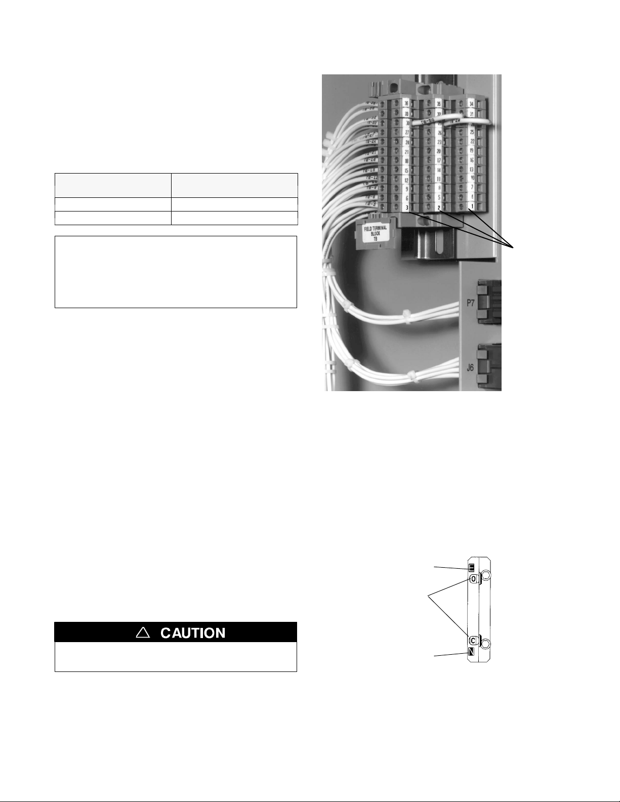
Engine Starting Contacts
All customer connections, including the engine control
contact connections, are located on terminal block TB
which is mounted on the t op right side of the enclosure.
Refer to the wiring diagram provided wit h the automatic
transfer switch and connect the engine start wires to the
appropriate terminals. See Figure 1–1 and Table A.
Table A. Engine start connections.
When normal source
fails
contact closes TB1 and TB2
contact opens TB1 and TB3
Te r mi na ls o n
Te r mi na l B l oc k T B
Note: To temporarily disable engine control from
the automatic transfer switch you can unplug J3
from the small P3 receptacle at the bottom of the
assembly. BesuretoreconnectplugJ3totheP3
receptacle for automatic transfer switch operation.
Auxiliary Circuits
Connect auxiliary circuit wires to appropriate terminals
on transfer switch terminal block TB a s shown on the
wiring diagram provided with this automatic transfer
switch.
engine start
connections
on
customer
terminal
block TB
Figure 1-1. Customer terminal block on the top right
side of the enclosure.
Functional Test
The Functional Test consists of three checks:
❐ 1 — Manual Operation Test, page 1–3
❐ 2—VoltageChecks,page1–4
❐ 3 — Electrical Operation, page 1–5
!
Do these checks in the order presented
to avoid damaging the ACTS.
Read all instructions on the Wiring Diagram and labels
affixed to the automatictransfer switch. Note the control
features that are provided and review their operation
before proceeding.
Note the position of the contact shafts as shown below.
Emergency contacts
(upper shaft)
window indicators
O is open
C is closed
position
indicators
(right side)
Normal contacts
(lower shaft)
Figure 1-2. Contact position indicators.
Shown with Emergency open and Normal closed.
Continue to 1–ManualOperationTest on next page.
1 --- 2
contact
Page 6
INSTALLATION (continued)
N
l
E
1 – Manual Operation Test
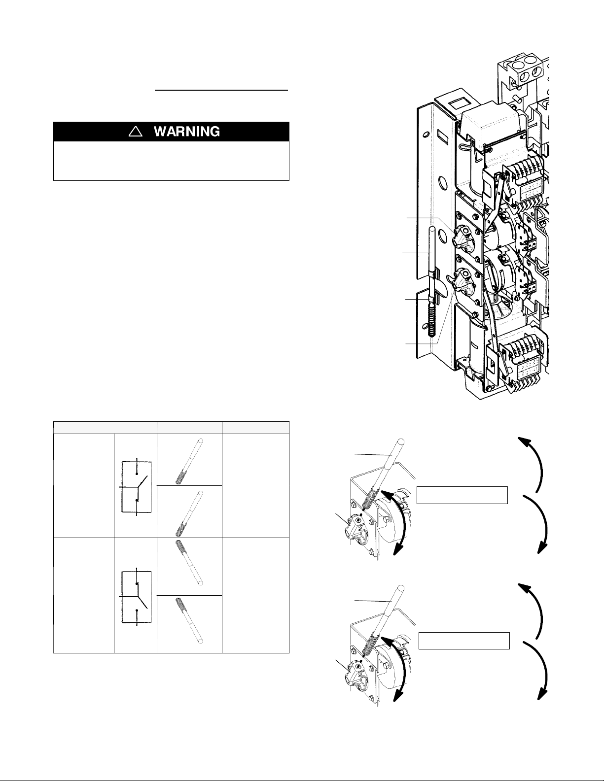
A detachable maintenance handle is provided on the frame
of the Transfer Switch for maintenance purposes only
Manual operation of the transfer switch should be
checked before it is energized (operated electrically).
!
Do not manually operate the transfer switch
until both power sources are disconnected:
open both circuit breakers.
1. After deenergizing both power sources, open the
enclosure door. Locate and removethe maintenance
handle from the clips on the left side of the transfer
switch frame. Insert the handle into the hole in the
molded hub on the left side of the operator. See
Figures 1–3 through 1–5 and Table B.
2. Mo ve the mainte nance ha ndle up or down as shown
to manually operate the transfer switch. The transfer
switch should operate smoothly without binding. If it
does not, check for shipping damage or construction
debris. Operate both upper and lower contact shafts.
.
left side of
transfer switch
Emergency source
contact shaft hub
maintenance
handle
clip
3. Retur n the transfer switch to the Normal position.
Observe that the window indicators (right side) show
the upper shaft O (Emergency open) and the lower
shaft C (Normal closed). Remove the maintenance
handle and store it on the frame in the clips provided.
Table B . Maintenance handle positions.
ATS Position Handle Indicators
up
E=O
upper contacts open
N=C
lower contacts closed
E=C
upper contacts closed
N=O
lower contacts open
orma
mergency
E
up
N
E
down
N
Normal source
contact shaft hub
Figure 1-3. Maintenance handle storage location.
HubsshownwithNormalclosed&Emergencyopen.
handle
UP opens the
Emergency source
contacts
UPPER SHAFT
hub
DOWN closes the
Emergency source
contacts
frame
Figure 1-4. Emergency (upper shaft) operation.
handle
UP closes the
Normal source
contacts
down
Note: If Normal and Emergency connections are
reversed this operation is also reversed.
hub
LOWER SHAFT
DOWN opens the
Normal source
contacts
Now continue to 2–VoltageChecks on the next page.
frame
Figure 1-5. Normal (lower shaft) operation.
1 --- 3
Page 7
INSTALLATION (continued)
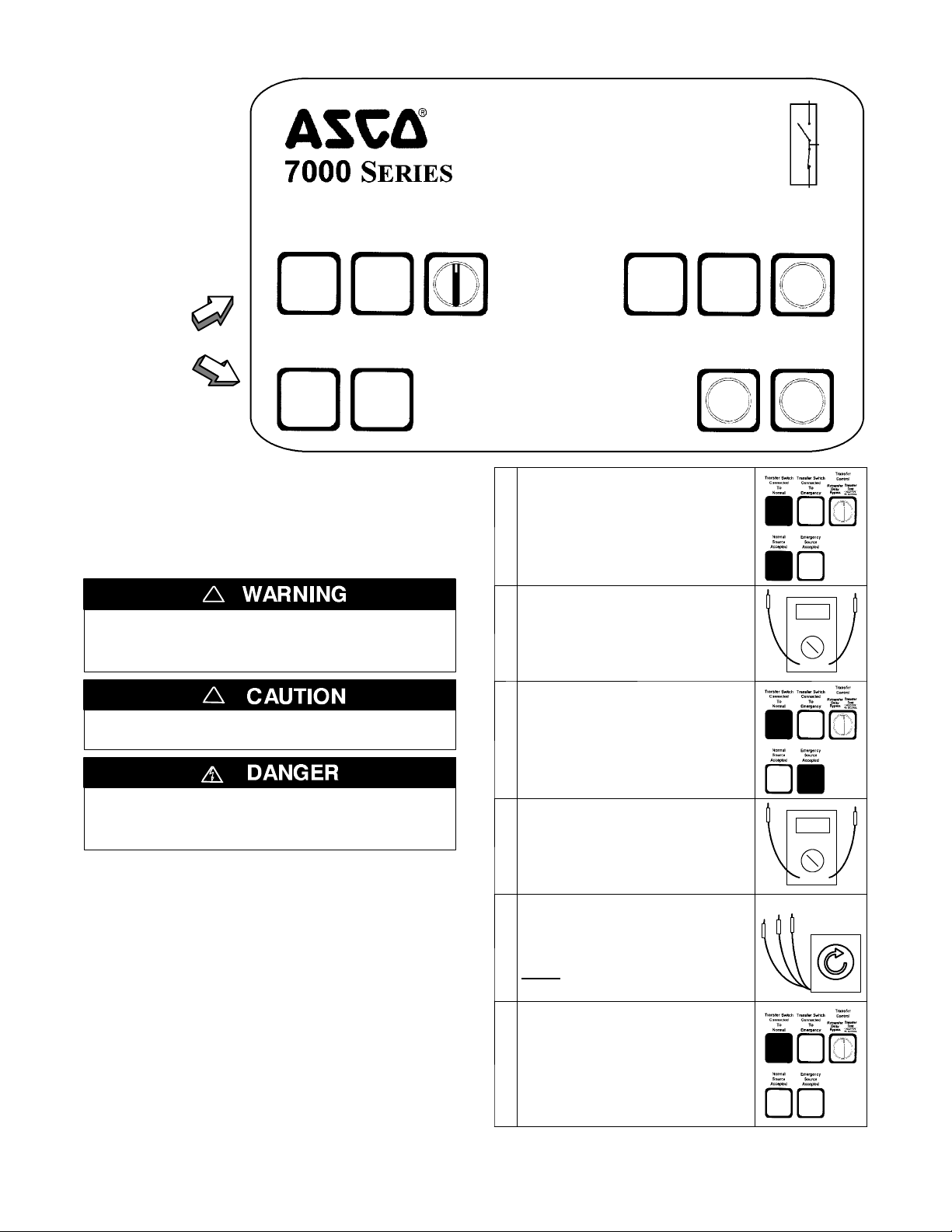
Automatic Closed Transition
Tra n s fer Switc h
Tra n sf e r
Control
Retransfer
Delay
Bypass
observe
these lights
Tra n sf e r Sw i t ch
Connected
To
Normal
GREEN
Normal
Source
Accepted
GREEN
Tra n sf e r Sw i t ch
Connected
To
Emergency
RED
Emergency
Source
Accepted
RED
Figure 1-6. Standard controls and indicators.
2 --- V o l t a g e C h e c k s
First check nameplate on transfer switch; rated voltage
mustbethesameasnormalandemergencylinevoltages.
!
Before energizing the switch check to be sure
that both normal and emergency contacts are
notleftintheclosedposition.
Tra ns f er
Tes t
HOLD F OR
(
15 SEC ONDS
Extended
Parallel
)
Time
RED RED RED
Close the normal source circuit
breaker. The Transfer Switch
Connected To Normal and the
1
Normal Source Accepted lights
should come on.
Use an accurate voltmeter to
check phase to phase and
phase to neutral voltages pres-
2
entatthetransferswitchnormal
source terminals.
Failure
To
Synchronize
Alarm
Reset
TS
Locked
Out
Closed
Tra n si t i o n
Bypass
!
Verify that the feeders have been
connected to the proper lugs.
Useextremecautionwhenusingameterto
measure voltages. Do not touch power termi-
nals; shock, burns, or death could result !
Performsteps 1 through 6 at the right. Observe the status
lights. See Figure 1--- 6.
■ Black square means light is on.
❐ White square means light is off.
* If necessary, adjust voltage regulator on the generator
according to the manufacturer’s recommendations. The
Automatic Transfer Switch will respond only to the rated
voltage specified on the Transfer Switch nameplate.
Note: Refer to Section 3 of Group 5 Controller User’s
Guide 381333–126 for how to display the Status of the
ATS and the Voltage and Frequency of each source.
Now continue to 3 --- Electrical Operation on next page.
Close the emergency source
circuit breaker. (Start generator,
if necessary.) The Transfer
3
Switch Connected To Normal &
Emergency Source Accepted
lights should come on.
Use an accurate voltmeter to
check phase to phase and
phase to neutral voltages pres-
4
ent at the transfer switch emergency source terminals.*
Useaphaserotationmeterto
check phase rotation of emer-
5
gency source; it must be the
same
as the normal source.
Shut down the engine–generator , if applicable. The Emergen-
cy Source Accepted light should
go off. Then put the starting
6
control selector switch (on the
generator set) in the automatic
position. Close enclosure door.
C
B
A
1 --- 4
Page 8
INSTALLATION (continued)
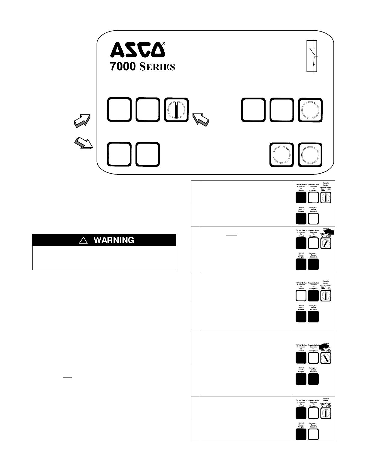
Automatic Closed Transition
Tra n s fer Switc h
Tra n sf e r
Control
Retransfer
Delay
Bypass
observe
these lights
Tra n sf e r Sw i t ch
Connected
To
Normal
GREEN
Normal
Source
Accepted
GREEN
Tra n sf e r Sw i t ch
Connected
To
Emergency
RED
Emergency
Source
Accepted
RED
Figure 1-7. Standard controls and indicators.
3 --- Electrical Operation
This procedure will check the electrical operation of the
Automatic Closed–Transition Transfer Switch. See
F i g u r e 1 --- 7 .
!
Close the enclosure door first.
Tra ns f er
Tes t
HOLD F OR
(
15 SEC ONDS
Extended
Parallel
)
Time
RED RED RED
operate
this switch
The Transfer Switch Connected
To Normal and Normal Source
1
Accepted lights should be on.
Turn a nd h o l d Transfer Co n trol
switch clockwise to Transfer Test
until the engine starts and runs
2
(within 15 sec.). Emergency
Source Accepted light should
come on.
Failure
To
Synchronize
Alarm
Reset
TS
Locked
Out
Closed
Tra n si t i o n
Bypass
Transfer Test
Both normal and emergency sources must be available
and the emergency source generator (if used) must be
capable of being started in this procedure.
Performsteps 1 through 5 at the right. Observe the status
lights.
■ Black square means light is on.
❐ White square means light is off.
** If you do not
Closed Transition Bypass pushbutton while the
controller display shows Waiting for In–Sync.Thisaction
causes open–transition (momentary load interruption)
transfer to the opposite source, if conditions permit.
Also refer to the Group 5 Controller User’s Guide
381333–126.
This completes the Functional Test of the ACTS.
want closed–transition transfer, press the
Transfer switch CE closes and
then Transfer Switch CN opens
(closed–transition overlap). The
Transfer Switch Connected To
Emergency light should come on
3
and the Transfer Switch
Connected to Normal light goes
off (you might see and hear the
brief overlap transfer). **
Transfer switch will operate back
to Normal position after Feature
3A time delay. For immediate
retransfer turn Transfe r Control
counterclockwise to Retransfer
4
Delay Bypass.TheTransfer
Switch Connected To Normal light
should come on; Transfer Switch
Connected to Emergency light
should go off.
The engine–generator will stop
after the Feature 2E time delay
(unloaded running engine cool-
5
down). The Emergency Source
Accepted light should go off.
1 --- 5
Page 9
SECTION 2 TESTING & SERVICE
TRANSFER TEST
Operate the 7000 Series ACTS at least once a month by
following the five–step Electrical Operation Transfer
Tes t procedure on page 1–5.
PREVENTIVE MAINTENANCE
Reasonable care in preventive maintenance will insure
high reliability and long life for the 7000 Series ACTS.
An annual preventive maintenance program is recommended.
In the United States, ASCO Services, Inc. (ASI) is
ASCO Power Technologies’s national service
organization. ASI can be contacted at
1-800-800-2726 (ASCO) for information on
preventive maintenance agreements.
In Canada, for service call 1-888-234-2726 (ASCO).
Checklist for Yearly Inspection
Hazardous voltage capable of causing shock,
burns, or death is used in this transf er switch.
Deenergize both Normal – Emergency power
sources before performing inspections!
❐ Clean the ACTS enclosure. Brush and vacuum
away any excessive dust accumulation. Remove any
moisture with a clean cloth.
DISCONNECTING THE CONTROLLER
The harness disconnect plugs are furnished for repair
purposes only and should not have to be unplugged. If
the controller must be isolated, follow these steps:
Disconnecting the Plugs
!
Do not unplug the controller
until steps 1a or 1b is co m pleted.
1. Observe the position of the transfer switch.
a. If the transfer switch is in the Normal position, first
place standby engine starting control in the off
position. Second, then open the emergency source
circuit breaker. Third, open the normal source
circuit breaker.
b. If the transfer switchis in the Emergency position,
first open the normal source circuit breaker. Second, place the engine starting control in the test
or run position. Third, open the emergency source
circuit breaker.
2. Separate the two quick disconnect plugs by squeezing the latches. Do not pull o n the harness wires.
Reconnecting the Plugs
!
Do not reconnect the controller
until steps 1a or 1b is co m pleted.
❐ Check the transfer switch contacts.Removethe
transfer switch barriers and check contact condition.
Replace the contacts if they become pitted or worn
excessively. Reinstall the barriers carefully.
❐ Maintain transfer switch lubrication.Ifthe
transfer switch is subjected to severe dust or
abnormal operating conditions, renew factory
lubrication on all movements and linkages.
Re l u b r ic ate the solenoid operator if the TS coil is
replaced. Do not use oil; order lubrication kit 75-100.
❐ Check all cable connections & retighten them.
REPLACEMENT PARTS
Replacement parts are available in kit form. When ordering parts provide the Serial No., Bill of Mate rial No.
(BOM), and Catalog No. from the transfer switch nameplate. Contact your local ASCO Power Technologies
Sales Office or ASI:
in United States call 1 800 – 800 – ASCO (2726)
or in Canada call 1 888 – 234 – ASCO (2726)
1. Observe the position of the transfer switch.
a. If the transfer switch is in the Normal position,
firstbesurethatboth
source circuit breakers are open. Second, be sure
that the standby engine starting control is still in
the off position.
b. If the transfer switch is in the Emergency position,
firstbesurethatboth
source circuit breakers are open.
2. The two harness plugs and sockets are keyed. Carefully align the plugs wi th the sockets and press
straight in until both latches click. Close the door
3. Restore the two sources in sequence as follows:
a. If the transfer switch is in the Normal position,
first close the normal source circuit breaker.
Second, close the emergency source circuit breaker. Third, place the standby engine starting
control in the automatic position.
b. If the transfer switchis in the Emergency position,
first close the emergency source circuit breaker.
Second close the normal source circuit breaker.
normal and emergency
normal and emergency
!
2 --- 1
Page 10
TESTING & SERVICE
PROBLEM
(continued)
MANUAL LOAD TRANSFER
This procedure will manually transfer the load if the
controller is disconnected.
!
Do not manually operate the transfer switch
until both power sources are disconnected
(all conductors deenergized).
1. Deenergize both the normal and emergency source
conductors (remove fuses or open circuit breakers).
TROUBLE-SHOOTING
Note any optional accessories that may be furnished on
the ACTS and review their operation. Refer to any
separatedrawingsand/or instructions that may be packed
with the ACTS.
2. Use the maintenance handle to manually operate the
transfer switch to the opposite source. First open the
closed contacts, then close the other contacts. Do no
leave both closed
3. Then remove
.SeeManual Operation on page 1–3.
the maintenance handle. See page1–3.
!
Verify that the maintenance handle
has been removed before proceeding!
4. If the transfer switch is in the Emergency position
manually start the engine generator and then install
emergencysourcefuseorclosethecircuitbreaker.
Hazardous voltage capable of causing shock,
burns, or death is used in this switch.
Do not touch the power or load terminals
of the transfer switch!
t
Engine–generator set does
not start when the Tra nsfer
Control switch is turned and
held
in Transfer Test position
or when normal source fails.
T ransfer switch does not
transfer the load to the
emergency source after the
engine–generator set starts.
T ransfer switch does not
transfer the load to normal
source when normal returns
or when the Transfer Control
switch is released.
Gen. does not stop after load
retransfer to normal source.
Failure to Synchronize
light comes on.
Extended Parallel Time
light comes on.
TS Locked Out
light comes on.
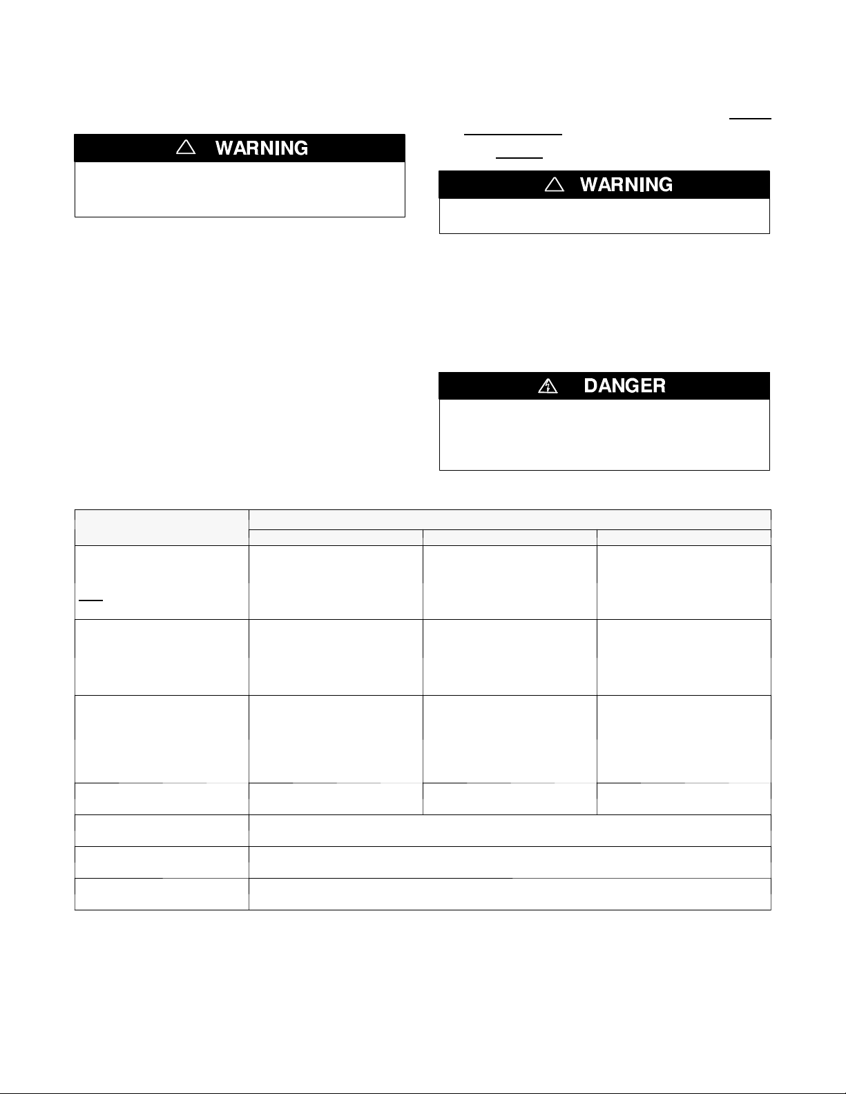
Table 2-1. Trouble-Shooting Checks.
CHECK IN NUMERICAL SEQUENCE
1OPERATION 2 GEN-SET 3VOLTAGE
Hold Transfer Test switch 15
seconds or the outage must
be long enough to allow for
Feature1Ctimedelayplus
engine cranking and starting.
Wait for Feature 2B time delay
to time out.
Wait for Feature 3A time delay
to time out.
Wait for Feature 2E time delay
to time out.
Conditions of Normal or Emergency Sources not suitable for closed transition transfer.
Recheck voltage and frequency of both sources. Press Alarm Reset pushbutton.
CN and CE contacts are closed longer than setting in the Control Panel. Open the discon-
nected source circuit breaker, then call your nearest ASCO Service Center for assistance.
Transfer lockout operation has occured; transfer switch is disabled from automatic operation.
Open the disconnected source circuit breaker, then call your nearest ASI for assistance.
Starting control must be in the
automatic position. Batteries
must be charged and
connected. Check wiring to
engine starting contacts.
Generator output circuit
breaker must be closed.
Generator frequency must be
at least 95% of nominal (57 Hz
for a 60 Hz system.) *
---
Starting control must be in the
automatic position.
---
Voltmeter should read at least
90% of nominal phase to
phase voltage between
terminals EA and EC (or EL1
and EL2 for 2 pole switches)*
Voltmeter should read at least
90% of nominal phase to
phase voltage between
terminals NB and NC, NC and
NA, and NA and NB (or NL1
and NL2 for 2 pole switches).
---
* These are factory settings. Refer to Group 5 Controller User’s Guide.
If the problem is isolated to circuits on the controller or t he transfer switch, call your local ASCO Power Technologies
sales office or ASI. In the United States, call 1–800–800–2726. In Canada, call 1–888–234–2726. Furnish the Serial No.
and Catalog No. from the transfer switch nameplate.
2 --- 2
Page 11

INDEX
A
alarm reset, 1–5, 2–2
auxiliary circuits, 1–2
C
cable
lugs, 1–2
preparation, 1–2
catalog number, inside cover
cleaning, 2–1
closed transition bypass, 1–5, 2–2
connections
line, 1–1
contact position indicators, 1–3
controller, 1–1
disconnecting, 2–1
see Controller User’s Guide
E
electrical operation, 1–5
emergency source accepted light,
1–4
extended parallel time, 2---2
F
I
inspection, 2–1
installation, 1–1
indicators, contact position, 1–3
L
labels,
engine start contacts, 1–2
rating, cover
lights, 1–4, 1–5
lubrication, 2–1
M
maintenance handle, 1–3
maintenance, preventive, 2–1
manual load transfer, 2–2
warning, 2–2
manual operation, 1–3
illustration of, 1–3
warning, 1–3
N
nameplate, cover
normal source accepted light, 1–4
O
S
settings
see Controller User’s Guide
T
test, functional, 1–2, 1–3, 1–4, 1–5
time delays, 2–1
see Controller User’s Guide
Transfer Control selector switch
Retransfer Delay Bypass, 1–5
Transfer Test, 1–5
Transfer Switch Connected To
Emergency light, 1–5, 2–1
Transfer Switch Connected To
Normal light, 1–4, 2–1
transfer test, 1–5
transfer to emergency, 1–5
transfer to normal, 1–5, 2–1
trouble–shooting, 2–2
T S l o c k e d o u t , 2 --- 2
V
voltage checks, 1–4
voltage, pickup and dropout settings
see Controller User’s Guide
f a i l u r e t o s y n c h r o n i z e , 2 --- 2
frequency, generator, 2–2
functional test, 1–2, 1–3, 1–4, 1–5
G
ground, controller, 1–1
H
harness, 1–1
disconnect plugs, 2–1
operation
electrical, 1–5
manual, 1–3
illustration of, 1–3
warning, 1–3
optional accessories
see Controller User’s Guide
P
parts, 2–1
phase rotation check, 1–4
problem, 2–2
R
rating label, cover
replacement parts, 2–1
Printed in U.S.A. Copyright --- ASCO Power Technologies 2006
 Loading...