

Supervisory Controller
Installation and Operation Manual
Site Supervisor Version 2.13
026-1800 Rev 18


Emerson Digital Solutions
Commercial and Residential Solutions
1065 Big Shanty Road NW, Suite 100
Kennesaw, GA 30144 USA
770-425-2724 • 1-800-829-2724
climate.emerson.com
Email:
ColdChain.TechnicalServices@Emerson.com
Solutions.CustomerService@Emerson.com
SUPERVISOR FIRMWARE VERSION
2.13F01
For more information on 2.13 features, see the Release Notes P/N 026-4064:
https://climate.emerson.com/documents/site-supervisor-release-notes-2-13f01-en-us-
1644516.pdf
FOR COMPLETE PRODUCT PART NUMBERS AND ORDERING,
CONTACT EMERSON SALES OR CUSTOMER SERVICE.
WARNING! The enclosure should
never be opened. Warranty void if
seal is tampered with or removed.
FCC COMPLIANCE NOTICE
This device complies with Part 15 of the FCC Rules Class A. Operation is subject to
the following two conditions: (1) this device may not cause harmful interference, and
(2) this device must accept any interference received, including interference that may
cause undesired operation.
CE COMPLIANCE NOTICE
Class A Product Information for Supervisory Controllers:
The Emerson Supervisory Controllers are Class A products. In a domestic
environment this product may cause radio interference in which case the user may be
required to take adequate measures.
ULE211299
ELECTROSTATIC DISCHARGE CAUTION
This integrated circuit can be damaged by ESD. Failure to observe proper handling and
installation procedures can cause damage. ESD damage can range from subtle
performance degradation to complete device failure. Precision integrated circuits may
be more susceptible to damage because very small parametric changes may cause the
device to not meet its published specifications.

CONTENTS
1 BASIC SETUP INFORMATION ............................................................................................................................. 1-1
1.1 E
THERNET CONNECTION............................................................................................................................................ 1-1
1.2 D
IRECT CONNECT INSTRUCTIONS - CONNECT YOUR LAPTOP TO SUPERVISORY CONTROLLER’S ETHERNET PORT ETH1
7-1
1.3 L
OGGING INTO THE SUPERVISORY CONTROLLER ...................................................................................................... 1-2
1.4 S
ETUP WIZARD .......................................................................................................................................................... 1-3
1.4.1 Localization Screen ............................................................................................................................................ 1-3
1.4.2 System Values Screen ......................................................................................................................................... 1-4
1.4.3 Network Settings Screen ..................................................................................................................................... 1-4
1.5 S
ITE SUPERVISOR RS485 WIRING GUIDE EXAMPLES................................................................................................ 1-5
2 BASIC NAVIGATION............................................................................................................................................... 2-1
2.1 M
ENUS AND SUBMENUS ............................................................................................................................................ 2-1
2.2 O
VERVIEW.................................................................................................................................................................. 2-2
2.2.1 Conditional Visibility.......................................................................................................................................... 2-2
2.2.1.1 User View Details.................................................................................................................................................... 2-2
2.3 BASIC SCREEN ELEMENTS ......................................................................................................................................... 2-2
2.4 L
ANGUAGE SETTINGS ................................................................................................................................................ 2-2
2.5 L
OCATING AND WORKING WITH APPLICATIONS....................................................................................................... 2-3
2.6 A
PPLICATION TABS .................................................................................................................................................... 2-4
2.6.1 Performance Meter............................................................................................................................................. 2-4
2.6.2 Site Aggregation ................................................................................................................................................. 2-4
2.6.3 Control Inventory ............................................................................................................................................... 2-5
2.6.3.1 Adding Applications................................................................................................................................................ 2-5
2.7 ADFS ......................................................................................................................................................................... 2-6
2.8 C
REATING A BACKUP AND RESTORE ......................................................................................................................... 2-6
2.8.2 Restore................................................................................................................................................................ 2-7
2.9 U
SING THE HELP MENU ............................................................................................................................................. 2-7
2.10 I
CONS OR BUTTONS APPEARING ON THE HOME SCREEN ........................................................................................ 2-8
3 ALARM CONFIGURATION .................................................................................................................................... 3-1
3.1 A
LARM CONFIGURATION .......................................................................................................................................... 3-2
3.2 A
LARM COMMUNICATIONS SETTING ........................................................................................................................ 3-2
3.3 A
LARM LOG AND VIEW HISTORY.............................................................................................................................. 3-4
3.4 TEMPERATURE DIFFERENTIAL ALARMS ................................................................................................................... 3-5
3.5 L
IGHTING CYCLE ALARMS ....................................................................................................................................... 3-7
3.6 SMART ALARMING ..................................................................................................................................................... 3-7
3.6.1 Accessing Smart Alarms ..................................................................................................................................... 3-7
3.7 P
EER ALARMING ........................................................................................................................................................ 3-9
3.8 G
ENERIC ALARMS...................................................................................................................................................... 3-9
3.9 A
LARM TYPES............................................................................................................................................................ 3-9
4 HARDWARE OVERVIEW ...................................................................................................................................... 4-1
4.1 O
RDERING INFORMATION........................................................................................................................................... 4-1
4.2 T
ECHNICAL SPECIFICATIONS...................................................................................................................................... 4-1
4.3 H
OUSING DIMENSIONS AND MOUNTING.................................................................................................................... 4-2
4.4 W
IRING DIAGRAMS .................................................................................................................................................... 4-3
4.5 D
EVICE WIRING ......................................................................................................................................................... 4-5
4.6 S
ITE SUPERVISOR POWER, SERIAL, AND IO POSITIONS............................................................................................. 4-5
4.6.1 Termination Jumpers.......................................................................................................................................... 4-5
4.6.2 Using a DC Volt Meter to Check Termination and Bias.................................................................................... 4-6
4.6.3 Removing The SD Card ...................................................................................................................................... 4-6
Supervisory Controller 2.13 Installation and Operation Manual Table of Contents • v

4.6.4 LEDs ................................................................................................................................................................... 4-6
4.6.5 Dip Switch Termination and Biasing.................................................................................................................. 4-7
4.7 W
IRING TERMINAL DETAIL ....................................................................................................................................... 4-8
4.8 D
IGITAL INPUTS ........................................................................................................................................................ 4-8
4.9 R
ELAY OUTPUTS ....................................................................................................................................................... 4-8
4.10 A
4.11 S
4.12 F
NALOG INPUTS ...................................................................................................................................................... 4-9
ERIAL CONNECTIONS ........................................................................................................................................... 4-10
IRMWARE UPGRADE ............................................................................................................................................. 4-10
4.12.1 Firmware Update - Remote Access ................................................................................................................ 4-11
4.12.2 Firmware Update - USB Drive....................................................................................................................... 4-11
4.13 U
PLOADING SETPOINT FILES TO SUPERVISORY CONTROLLER .............................................................................. 4-13
5 RS485 I/O NETWORK BOARDS AND PERIPHERALS ..................................................................................... 5-1
5.1 T
HE I/O NETWORK..................................................................................................................................................... 5-1
5.2 I/O B
OARD NAMES AND TERMINOLOGY.................................................................................................................... 5-1
5.2.1 MultiFlex Boards................................................................................................................................................ 5-1
5.2.1.1 MultiFlex 16 Input Board........................................................................................................................................ 5-1
5.2.1.2 MultiFlex Combination Input/Output Boards.........................................................................................................
5-2
5.2.2 MultiFlex CUB Support...................................................................................................................................... 5-3
5.2.3 MultiFlex RTU Support ...................................................................................................................................... 5-3
5.2.3.1 I/O Network and MultiFlex RTU Setup on Serial Port........................................................................................... 5-3
5.2.3.2 Creating an Instance of RTU Application...............................................................................................................
5.2.3.3 Deleting/Checking Status of RTU Board................................................................................................................
5.2.3.4 Zone Management...................................................................................................................................................
5.2.3.5 Scheduling...............................................................................................................................................................
5.2.3.6 Alarming..................................................................................................................................................................
5.2.3.7 Real Time Clock Updates .......................................................................................................................................
5.2.3.8 Hand-Held Terminal Support..................................................................................................................................
5-4
5-4
5-4
5-4
5-4
5-4
5-4
5.2.4 MultiFlex RCB Support ...................................................................................................................................... 5-4
5.2.4.1 I/O Network and MultiFlex RCB Setup on Serial Port........................................................................................... 5-4
5.2.4.2 Creating an Instance of RCB Application...............................................................................................................
5.2.4.3 Deleting/Checking Status of RCB Board................................................................................................................
5.2.4.4 Zone Management...................................................................................................................................................
5.2.4.5 Scheduling...............................................................................................................................................................
5.2.4.6 Alarming..................................................................................................................................................................
5.2.4.7 Real Time Clock Updates .......................................................................................................................................
5.2.4.8 Hand-Held Terminal Support..................................................................................................................................
5-5
5-5
5-5
5-6
5-6
5-6
5-6
5.2.5 MultiFlex RTU.................................................................................................................................................... 5-6
5.2.6 MultiFlex Rooftop Control Board (RCB) ........................................................................................................... 5-6
5.2.7 The MultiFlex ESR Board................................................................................................................................... 5-7
5.2.8 Hand-held Terminal (P/N 814-3110) ................................................................................................................. 5-7
5.2.9 The 8RO and 8ROSMT Relay Boards ................................................................................................................ 5-8
5.2.10 4AO Analog Output Board ............................................................................................................................... 5-9
5.2.11 8DO Digital Output Board ............................................................................................................................... 5-9
5.
2.12 XM Series of Case Controllers ......................................................................................................................... 5-9
5.2.12.1 XM670K v3.4 ....................................................................................................................................................... 5-9
5.2.12.2 XM679K v3.4 and v4.2.........................................................................................................................................
5.2.12.3 XM678D v2.5 and v2.8.......................................................................................................................................
5-9
5-10
5.2.13 XEV22 v1.1 and v1.5 ...................................................................................................................................... 5-10
5.2.14 Wireless I/O .................................................................................................................................................... 5-10
5.2.15 Supervisor Displays........................................................................................................................................ 5-11
5.2.16 Emerson Programmable Touchscreen Thermostat ........................................................................................ 5-11
5.2.17 Control Techniques Drive (VSD) ................................................................................................................... 5-12
5.2.18 DAC ................................................................................................................................................................ 5-12
5.2.19 Copeland Discus with
vi • Table of Contents 026-1800 Rev 18

CoreSense Diagnostics (ISD)...................................................................................................................................... 5-13
5.2.20 Copeland Discus with
CoreSense Protection................................................................................................................................................. 5-13
5.2.21 Copeland Scroll – K5
Refrigeration Compressor........................................................................................................................................... 5-13
6 WIRING EXAMPLES ........................................................................................................................................... 6-1
7 SITE SUPERVISOR DISPLAYS ............................................................................................................................ 7-1
7.1 10.1-I
NCH TOUCHSCREEN DISPLAY .......................................................................................................................... 7-1
7.1.1 Display Connections .......................................................................................................................................... 7-1
7.1.2 Specifications ..................................................................................................................................................... 7-2
7.1.3 Mounting Dimensions ........................................................................................................................................ 7-2
7.1.4 Direct Connect to Site Supervisor...................................................................................................................... 7-3
7.2 15.6-I
NCH TOUCHSCREEN DISPLAY .......................................................................................................................... 7-4
7.2.1 Display Connections .......................................................................................................................................... 7-4
7.2.2 Specifications ..................................................................................................................................................... 7-4
7.2.3 Mounting Dimensions ........................................................................................................................................ 7-5
7.2.4 Direct Connect to Site Supervisor...................................................................................................................... 7-5
7.3 21.5-I
NCH TOUCHSCREEN DISPLAY .......................................................................................................................... 7-6
7.3.1 Display Connections .......................................................................................................................................... 7-6
7.3.2 Specifications ..................................................................................................................................................... 7-7
7.3.3 Mounting Dimensions ........................................................................................................................................ 7-7
7.3.4 Direct Connect to Site Supervisor...................................................................................................................... 7-8
7.4 S
ITE SUPERVISOR TOUCHSCREEN DISPLAY VERSION COMPATIBILITY..................................................................... 7-9
8 SOFTWARE OVERVIEW ...................................................................................................................................... 8-1
8.1 E
MERSON SUPERVISORY CONTROL APPLICATION AND SYSTEM CAPACITY MATRIX............................................... 8-1
8.2 E
MERSON SITE AGGREGATOR FEATURES ................................................................................................................. 8-6
8.3 E
MERSON SYSTEM SUPERVISOR FEATURES .............................................................................................................. 8-7
8.4 E
MERSON SUPERVISORY CONTROL MODEL SELECTION GUIDE ............................................................................... 8-8
8.5 E
MERSON SUPERVISORY CONTROL TO E2 CROSS-REFERENCE GUIDE ................................................................... 8-10
8.6 E
MERSON SUPERVISORY CONTROL NEW FEATURES .............................................................................................. 8-11
8.7 S
UCTION GROUPS .................................................................................................................................................... 8-12
8.7.1 Introduction...................................................................................................................................................... 8-12
8.7.2 The (Standard) Suction Group Application ..................................................................................................... 8-12
8.7.2.1 Overview of PID Control Strategy ........................................................................................................................ 8-12
8.7.2.2 Variable-Speed Compressors................................................................................................................................. 8-12
8.7.2.3 Floating Setpoint Control....................................................................................................................................... 8-12
8.7.3 The Enhanced Suction Group Application....................................................................................................... 8-12
8.7.3.1 Learning Mode....................................................................................................................................................... 8-13
8.7.3.2 Circuit Load Analysis ............................................................................................................................................ 8-13
8.7.3.3 The Control/Cycles Parameter............................................................................................................................... 8-13
8.7.3.4 Variable-Speed, Digital Scroll, and Digital Discus Compressor Support ............................................................. 8-13
8.7.3.5 Floating Suction Control........................................................................................................................................ 8-13
8.7.4 Hardware Overview......................................................................................................................................... 8-13
8.8 A
NALOG SENSOR CONTROL .................................................................................................................................... 8-14
8.8.1 Control Strategy............................................................................................................................................... 8-14
8.8.2 Control Alarming ............................................................................................................................................. 8-15
8.8.3 Alarm Output When On/Off Parameters.......................................................................................................... 8-15
8.8.4 Control Bypass................................................................................................................................................. 8-15
8.9 D
IGITAL SENSOR CONTROL..................................................................................................................................... 8-15
8.9.1 Control Strategy............................................................................................................................................... 8-16
8.9.2 Command Alarming ......................................................................................................................................... 8-16
8.9.3 Alarm Output When On/Off Parameters.......................................................................................................... 8-16
Supervisory Controller 2.13 Installation and Operation Manual Table of Contents • vii

8.9.4 Control Bypass ................................................................................................................................................. 8-16
8.10 L
IGHTING CONTROL .............................................................................................................................................. 8-17
8.10.1 Lighting Control Logic................................................................................................................................... 8-17
8.10.2 Light Level Sensor Verification...................................................................................................................... 8-17
8.10.3 Solar Calculation ........................................................................................................................................... 8-17
8.10.4 Digital Lighting Output.................................................................................................................................. 8-18
8.10.5 Light Proofing ................................................................................................................................................ 8-18
8.10.6 Minimum On/Off Times.................................................................................................................................. 8-18
8.10.7 Dimming Control (Analog Output) ................................................................................................................ 8-18
8.10.8 External Schedule........................................................................................................................................... 8-19
8.10.9 Lighting Bypass Inputs................................................................................................................................... 8-19
8.10.10 Demand Shed Behavior................................................................................................................................ 8-20
8.11 G
LOBAL DATA....................................................................................................................................................... 8-20
8.11.1 Location From................................................................................................................................................ 8-20
8.11.2 Sundown ......................................................................................................................................................... 8-20
8.12 HVAC C
ONTROL ................................................................................................................................................... 8-20
8.12.1 Active Setpoint Determination ....................................................................................................................... 8-20
8.12.2 Setpoint Reset ................................................................................................................................................. 8-21
8.12.3 Demand Shed.................................................................................................................................................. 8-21
8.12.4 Heating and Cooling Control......................................................................................................................... 8-21
8.12.5 Control Logic ................................................................................................................................................. 8-21
8.12.6 Heat/Cool Lockout Based on Outside Air Temperature ................................................................................ 8-22
8.12.7 System Shutdown............................................................................................................................................ 8-22
8.12.8 Fan Control.................................................................................................................................................... 8-22
8.12.9 Fan Mode ....................................................................................................................................................... 8-22
8.12.10 Plenum Warmup/Purge................................................................................................................................ 8-22
8.12.11 Fan Proof Failure ........................................................................................................................................ 8-22
8.12.12 System Shutdown.......................................................................................................................................... 8-22
8.12.13 Economization (Damper) Control................................................................................................................ 8-23
8.12.14 Determine the Analog Damper Position ...................................................................................................... 8-23
8.12.15 Determine the Digital Damper Position ...................................................................................................... 8-24
8.12.16 Heat Pump Control ...................................................................................................................................... 8-24
8.12.17 Reversing Valve............................................................................................................................................ 8-24
8.12.18 Compressor Output ...................................................................................................................................... 8-24
8.12.19 Curtailment................................................................................................................................................... 8-24
8.13 T
IME SCHEDULE APPLICATION.............................................................................................................................. 8-24
8.13.1 Time Schedule Method ................................................................................................................................... 8-24
8.13.2 Standard Schedule.......................................................................................................................................... 8-25
8.13.3 Event Names................................................................................................................................................... 8-25
8.13.4 Maintenance Schedule.................................................................................................................................... 8-25
8.13.5 Maintenance Overrides.................................................................................................................................. 8-25
8.13.6 Output Calculation......................................................................................................................................... 8-27
8.13.7 Scheduling Logic............................................................................................................................................ 8-27
8.13.8 Control Override............................................................................................................................................ 8-28
8.13.9 Control Bypass ............................................................................................................................................... 8-28
8.13.10 Control Override.......................................................................................................................................... 8-28
8.13.11 Special Conditions........................................................................................................................................ 8-28
8.13.12 Priority of Services....................................................................................................................................... 8-28
8.13.13 Control Alarming ......................................................................................................................................... 8-29
8.13.14 Schedule Category........................................................................................................................................ 8-29
8.14 D
EMAND CONTROL................................................................................................................................................ 8-29
8.14.1 KWH Calculation ........................................................................................................................................... 8-29
8.14.2 Demand Calculation ...................................................................................................................................... 8-29
8.14.3 Shed Outputs .................................................................................................................................................. 8-29
viii • Table of Contents 026-1800 Rev 18

8.14.4 Application Alarms ........................................................................................................................................ 8-30
8.14.5 KW Load Specification................................................................................................................................... 8-30
8.14.6 Performance Requirements............................................................................................................................ 8-30
8.15 U
TILITY MONITORING ........................................................................................................................................... 8-31
8.15.1 Utility Usage Calculation .............................................................................................................................. 8-31
8.15.1.1 Utility Type.......................................................................................................................................................... 8-31
8.15.1.2 Analog Input ........................................................................................................................................................ 8-31
8.15.1.3 Digital Pulse Input ............................................................................................................................................... 8-31
8.15.1.4 Current/Voltage Inputs - Single/Three Phase ...................................................................................................... 8-31
8.15.2 Consumption Totalizing ................................................................................................................................. 8-31
8.15.2.1 Totalizer Output................................................................................................................................................... 8-31
8.15.2.2 Fixed Period Totalizers........................................................................................................................................ 8-31
8.15.3 Demand Trip .................................................................................................................................................. 8-31
8.15.3.1 Shed Output ......................................................................................................................................................... 8-31
8.15.3.2 Average Rate of Consumption Output................................................................................................................. 8-32
8.15.3.3 Demand Alarm..................................................................................................................................................... 8-32
8.15.3.4 Time In Shed Output............................................................................................................................................ 8-32
8.15.4 Application Specific Logs............................................................................................................................... 8-32
8.15.5 Units of Measurement .................................................................................................................................... 8-32
8.16 P
OWER MONITORING............................................................................................................................................. 8-32
8.16.1 Overview ........................................................................................................................................................ 8-32
8.16.2 Logging .......................................................................................................................................................... 8-33
8.16.2.1 Power Monitoring Input....................................................................................................................................... 8-33
8.17 ONBOARD I/O ....................................................................................................................................................... 8-34
8.17.1 Licensing ........................................................................................................................................................ 8-34
8.17.2 Adding and Deleting Onboard I/O Application............................................................................................. 8-34
8.17.3 Status and Detail Screen ................................................................................................................................ 8-35
8.17.4 Alarming......................................................................................................................................................... 8-36
8.18 XR75CX 5.6.......................................................................................................................................................... 8-36
8.19 XR35CX 5.6
AND 2.6............................................................................................................................................ 8-36
8.19.1 Overview ........................................................................................................................................................ 8-37
8.19.2 Command-Alarm Matrix ............................................................................................................................... 8-37
8.20 XC645CX 2.5........................................................................................................................................................ 8-39
8.20.1 Application Advisories ................................................................................................................................... 8-40
8.20.2 Command-Alarm Matrix ............................................................................................................................... 8-40
8.21 XR75CX C
ASE DISPLAY....................................................................................................................................... 8-42
8.21.1 Overview ........................................................................................................................................................ 8-42
8.21.2 Application Advisories ................................................................................................................................... 8-42
8.21.3 Inputs.............................................................................................................................................................. 8-43
8.22 XR75CX 2.6.......................................................................................................................................................... 8-44
8.22.1 Application Advisories .................................................................................................................................. 8-44
8.22.2 Command ....................................................................................................................................................... 8-45
8.23 E
MERSON T-STAT.................................................................................................................................................. 8-45
8.23.1 General Control ............................................................................................................................................. 8-45
8.23.2 Alarms ............................................................................................................................................................ 8-45
8.23.3 Device Commissioning................................................................................................................................... 8-45
8.24 T
8.25 E
8.26 D
8.27 F
8.28 RLDS (R
OUCH T-STAT ...................................................................................................................................................... 8-46
NERGY METER..................................................................................................................................................... 8-46
ATA LOGGING AND GRAPH................................................................................................................................. 8-46
LEXIBLE COMBINER............................................................................................................................................. 8-46
EFRIGERANT LEAK DETECTOR SYSTEM)................................................................................................ 8-47
8.28.1 Communication .............................................................................................................................................. 8-47
8.28.2 Supported Gases ............................................................................................................................................ 8-47
8.29 ECB VAV ............................................................................................................................................................. 8-48
8.30 MRLDS (M
ODULAR REFRIGERANT LEAK DETECTOR SENSORS)......................................................................... 8-48
Supervisory Controller 2.13 Installation and Operation Manual Table of Contents • ix

8.31 CONTROL LINK ANTI-CONDENSATE CONTROLLER (CL ACC)............................................................................. 8-49
8.31.1 Alarm Handling Logic.................................................................................................................................... 8-49
8.31.2 Alarms Configuration..................................................................................................................................... 8-49
8.32 HVAC Z
ONE.......................................................................................................................................................... 8-49
8.32.1 How It Works.................................................................................................................................................. 8-49
8.32.2 Compatible Applications to be Connected to HVAC Zones........................................................................... 8-49
8.32.3 Temperature Control...................................................................................................................................... 8-50
8.32.4 HVAC Zone Temperature............................................................................................................................... 8-50
8.32.5 Economizer Control ....................................................................................................................................... 8-50
8.32.6 Economization Enable.................................................................................................................................... 8-50
8.32.7 The Effect of Enabling Economization........................................................................................................... 8-51
8.32.8 Dehumidification Control .............................................................................................................................. 8-51
8.32.9 HVAC Zone Humidity Input ........................................................................................................................... 8-51
8.32.10 Enabling Dehumidification Effect................................................................................................................ 8-51
8.32.10.1 MultiFlex RTUs and RCBs................................................................................................................................ 8-51
8.32.11 Optimum Start/Stop (OSS) ........................................................................................................................... 8-51
8.32.12 Intelligent Pre-Starts and Pre-Stops ............................................................................................................ 8-52
8.32.13 Setpoint Reset ............................................................................................................................................... 8-52
8.33 AHU ...................................................................................................................................................................... 8-53
8.34 A
8.35 A
8.36 C
NALOG AND DIGITAL COMBINER ........................................................................................................................ 8-53
NTI-SWEAT CONTROL ......................................................................................................................................... 8-54
ONDENSER CONTROL........................................................................................................................................... 8-54
8.36.1.1 Air Cooled Strategy ............................................................................................................................................. 8-54
8.36.1.2 Temperature Differential
Strategy ................................................................................................................................................................................ 8-54
8.36.2 Evaporative Condensers ................................................................................................................................ 8-55
8.36.3 Fan Control.................................................................................................................................................... 8-55
8.36.4 Condenser Split Mode .................................................................................................................................... 8-55
8.36.5 Fast Recovery................................................................................................................................................. 8-55
8.36.6 Hardware Overview ....................................................................................................................................... 8-55
8.37 S
8.38 C
TANDARD CIRCUITS ............................................................................................................................................. 8-56
ASE CONTROL CIRCUITS ..................................................................................................................................... 8-57
8.38.1 Overview......................................................................................................................................................... 8-57
8.38.2 Case Circuit Control Software Overview....................................................................................................... 8-57
8.38.2.1 Valve Control....................................................................................................................................................... 8-57
8.38.3 Refrigeration Control..................................................................................................................................... 8-58
8.38.3.1 EEVs (Liquid Pulse and Liquid Stepper)............................................................................................................. 8-58
8.38.3.2 EEPRs (Suction Stepper) ..................................................................................................................................... 8-58
8.38.4 Defrost Control ............................................................................................................................................. 8-59
8.38.4.1 Defrost States....................................................................................................................................................... 8-59
8.38.4.2 Defrost Types....................................................................................................................................................... 8-59
8.38.4.3 Defrost Termination............................................................................................................................................. 8-59
8.38.4.4 Demand Defrost................................................................................................................................................... 8-60
8.38.4.5 Emergency Defrost .............................................................................................................................................. 8-60
8.38.4.6 Defrost Schedule Summaries............................................................................................................................... 8-60
8.39 IRRIGATION CONTROL ........................................................................................................................................... 8-60
8.40 TD C
ONTROL ......................................................................................................................................................... 8-61
8.40.1 Overview......................................................................................................................................................... 8-61
8.40.2 Temperature Differential (TD) Strategy ........................................................................................................ 8-61
8.40.3 TD Control Fail-Safes.................................................................................................................................... 8-61
8.40.4 Configuration ................................................................................................................................................. 8-61
8.
40.5 Setpoints ......................................................................................................................................................... 8-62
8.40.6 Inputs.............................................................................................................................................................. 8-62
8.40.7 Alarms ............................................................................................................................................................ 8-62
8.41 L
OOP/SEQUENCE CONTROL ................................................................................................................................... 8-62
x • Table of Contents 026-1800 Rev 18

8.42 MODULAR CHILLER CONTROL .............................................................................................................................. 8-63
8.42.1 Learning Mode............................................................................................................................................... 8-63
8.42.2 The Control/Cycles Parameter ...................................................................................................................... 8-64
8.42.3 Compressor Control....................................................................................................................................... 8-64
8.42.3.1 Digital Scroll Compressor.................................................................................................................................... 8-64
8.42.3.2 Variable Frequency Drive Compressor ............................................................................................................... 8-65
8.42.3.3 Unequal Capacity Compressors........................................................................................................................... 8-65
8.42.4 Bypass Valve Control..................................................................................................................................... 8-65
8.43 XM C
IRCUIT CONTROL ......................................................................................................................................... 8-65
8.43.1 Associations ................................................................................................................................................... 8-65
8.43.1.1 Case Circuit Association Support ........................................................................................................................ 8-65
8.43.1.2 Dual Association Not Supported ......................................................................................................................... 8-66
8.43.1.3 Synchronized Parameters..................................................................................................................................... 8-66
8.43.1.4 Visibility of Associated Parameters..................................................................................................................... 8-66
8.43.2 Suction Group Interaction ............................................................................................................................. 8-66
8.43.2.1 Standard Suction .................................................................................................................................................. 8-66
8.43.2.2 Enhanced Suction................................................................................................................................................. 8-66
8.43.3 Supervisory Control Functions ...................................................................................................................... 8-66
8.43.3.1 Dewpoint Value ................................................................................................................................................... 8-66
8.43.3.2 Lighting Control................................................................................................................................................... 8-66
8.43.3.3 Active Setpoint Output ........................................................................................................................................ 8-66
8.43.3.4 Defrost Scheduling............................................................................................................................................... 8-67
8.43.3.5 Case States ........................................................................................................................................................... 8-67
8.43.3.6 Case Type............................................................................................................................................................. 8-67
8.43.4 Application Advisory...................................................................................................................................... 8-67
8.43.4.1 Synchronized Alarm Parameters.......................................................................................................................... 8-67
8.43.5 Application Commands .................................................................................................................................. 8-68
8.43.5.1 Start Defrost......................................................................................................................................................... 8-68
8.43.5.2 Stop Defrost ......................................................................................................................................................... 8-68
8.43.6 Product Probe Support .................................................................................................................................. 8-68
8.44 XR75CX C
8.45 B
OILER................................................................................................................................................................... 8-68
8.46 XJ C
8.47 CAN B
ASE DISPLAY....................................................................................................................................... 8-68
ONDENSING UNIT........................................................................................................................................... 8-68
US - IPX (EXPANSION MODULE) ............................................................................................................... 8-69
8.47.1 IPX 6 Relay .................................................................................................................................................... 8-71
8.47.2 IPX 15 Relay .................................................................................................................................................. 8-71
8.47.3 IPX 25 Relay .................................................................................................................................................. 8-71
8.48 S
UPPORTED REFRIGERANTS................................................................................................................................... 8-72
9 FLOOR PLANS ......................................................................................................................................................... 9-1
APPENDIX A: ALARM ADVISORIES.................................................................................................................... A-1
APPENDIX B: TROUBLESHOOTING.................................................................................................................... B-1
APPENDIX C: SETTING UP EMAIL AND TEXT ALERTS IN YOUR SUPERVISORY CONTROLLER . C-1
APPENDIX D: UTILITY MONITORING .............................................................................................................. D-1
APPENDIX E: PEER TO PEER NETWORK SETUP FOR MIXED SITES (2 SUPERVISORS AND 1 E2) .. E-1
Supervisory Controller 2.13 Installation and Operation Manual Table of Contents • xi
1 Basic Setup Information
1.1 Ethernet Connection
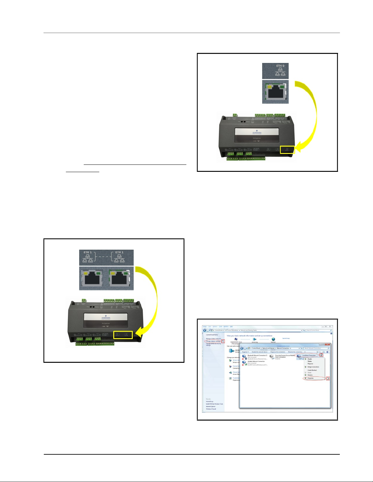
1. ETH1 is designed to be used for directly
connecting to laptop, PC, or optional touchscreen
with a CAT5 network cable.
2. The default IP for ETH1 is 192.168.1.250.
3. The optional touchscreen default IP is
192.168.1.200 and will connect automatically to
the Supervisory Controller when plugged into
ETH1. It is recommended that you do not change
these defaults.
4. ETH0 should be reserved for the secure network
connections: store or corporate networks. Ask
your network administrator for the correct
network IP address for ETH0.
5. ETH0 and ETH1 are physically separated for
added security. Directly connecting to ETH1 will
not access the secure network connection on
ETH0.
Figure 1-2 - Supervisory Controller ETH0 Port
1.2 Direct Connect
Instructions - Connect
your laptop to
Supervisory
Figure 1-1
Controller’s Ethernet
Port ETH1
1. Under Control Panel - Network and Sharing
Center, select Change adapter settings.
2. Select the Local Area Connection port being
used.
3. Select Properties.
- Supervisory Controller ETH1 Ports
Figure 1-3 - Change Adapter Settings
Ethernet Connection Basic Setup Information • 1-1

4. Highlight the section Internet Protocol Version
4 (TCP/IPv4) and click Properties:
1.3 Logging Into the Supervisory Controller
1. Launch a preferred Web browser: IE 9 and above,
Firefox 13 and above, Chrome (all versions), and
Safari (all versions) are the supported browsers.
2. Enter the IP Address of the device.
3. Enter the Username/Password (default user/pass)
and click Login. Update the password to the
minimum complexity requirements and click
Save. Note that after the first login using the
default user/pass, the password must be updated.
NOTE: When directly connecting your laptop
or PC to ETH1, enter the default IP into the
browser address bar: ETH1 Default IP
Address is 192.168.1.250.
Figure 1-4
- Highlight Internet Protocol Version 4 (TCP/IPv4)
5. Click Use the following IP address: and enter
the IP address 192.168.1.251 and the Subnet
mask 255.255.255.0 of the PC being used on the
Local Area Network or direct connection and
click OK:
Figure 1-6
To ensure the highest level of protection and security,
Emerson requires users to create passwords for logging
into Supervisor controllers that meet certain criteria and
National Institute of Standards and Technology (NIST)
recommendations.
• Passwords must contain 8 to 24 characters.
• Passwords cannot be composed of all the same
• Passwords cannot contain a commonly-used phrase.
- Login Screen at Controller Startup
characters (for example, “aaaaaaaa” or
“&&&&&&&&”).
Figure 1-5 - IP Address and Subnet Mask
1-2 • Supervisory Controller 2.13 Installation and Operation Manual 026-1800 Rev 18
1.4 Setup Wizard
If your unit has been received directly from the Emerson factory, the Setup Wizard will open and take you through the
following setup screens:
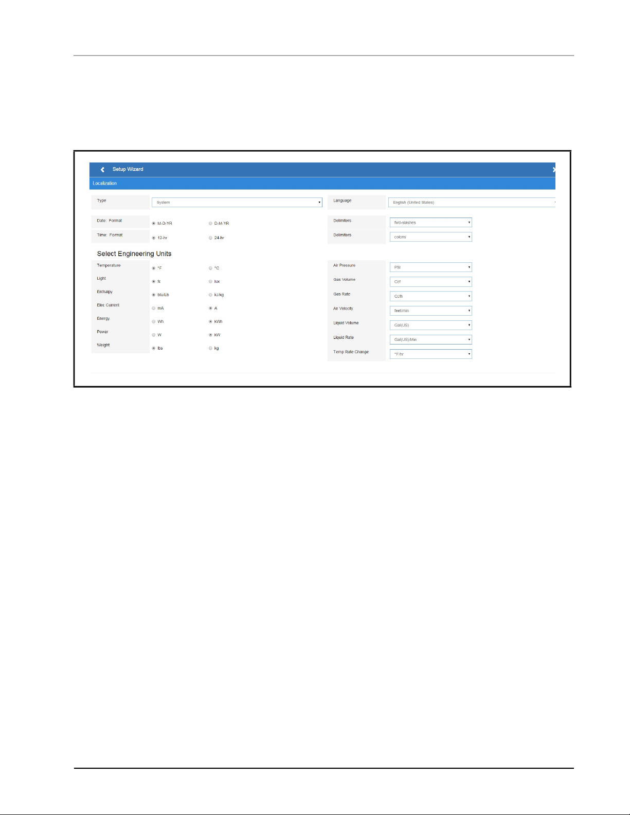
1.4.1 Localization Screen
Figure 1-7
Set the Supervisory Controller’s localization data such as language, date and time formats, and engineering units from the
Localization screen.
Language: The default for the language selection is American English (United States). The system stores a setting for the
preferred system language (internal language code). The default language is used when no user is currently logged into the
Supervisor or when the currently active preferred language does not have a translation for a given label, prompt, or
display text.
Date: The Date format can be set to either Day, Month, and full Year (D-M-YR) or Month-Day and full Year (M-D-YR)
format. The day, month, and year values are separated by either a forward slash or a dash line depending on user selection.
The Date Format can be changed based on user preference and saved to user profiles. On initial Supervisor startup, the
Date format defaults to the format of the language selected. For example, en-US will default to D-M-YR and all others
will default to M-D-YR.
Time: The Time format can be set to either a 12-hour (12-hr) format or 24-hour (24-hr) format. The hour, minute, and
second values are separated by either a colon or a period depending on user selection.The Time format can be changed
based on user preference and saved to user profiles. On initial Supervisor startup, the Time format defaults to the format of
the language selected. Date and Time delimiters default to forward slashes and colons.
Engineering Units: The default engineering units are based on the assigned units for the chosen preferred language.
Users can choose or change their preferred set of engineering units and save them to their user profiles. The default
engineering units are based on the International System of Units (SI System) format.
Set the system language type in the Language drop-down menu. Click the right arrow > to save and proceed to the
System Values screen.
- Localization Screen
Setup Wizard Basic Setup Information • 1-3
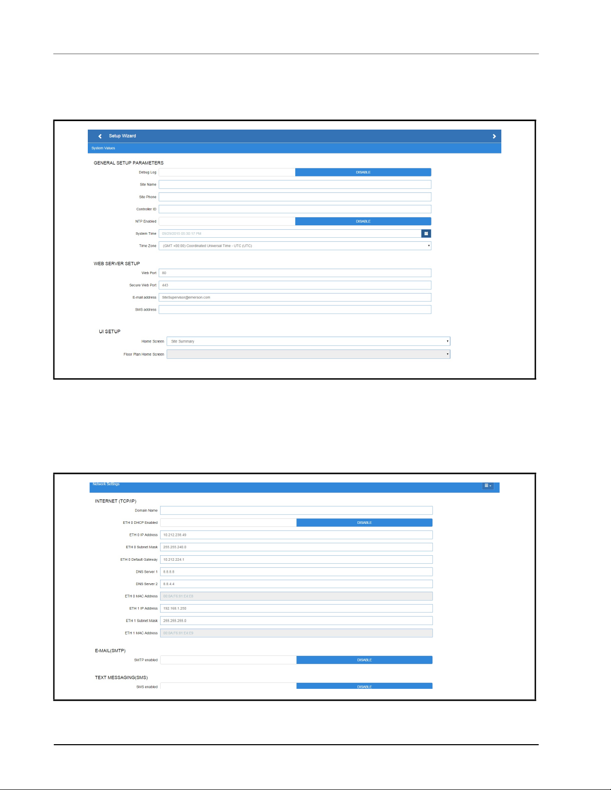
1.4.2 System Values Screen
From the System Values screen, name the unit by entering it in the Site Name field. The Confirmation window will slide
open. Click OK. Then click the right arrow > to proceed to the Network Settings Screen.
Figure 1-8
- System Values Screen
1.4.3 Network Settings Screen
Configure the settings on the Internet TCP/IP screen such as host name, text, and email settings. If you have Internet
access, enter the IP Subnet Mask and Default Gateway settings (see your IT Administrator). If connecting directly to a
laptop, use the Default IP and leave the DHCP set to Disable. For text messaging, enable the SMS setting and use the
SMTP address (see your IT Administrator).Click the arrow > to save and finish the Setup Wizard.
Figure 1-9 - Network Settings Screen
1-4 • Supervisory Controller 2.13 Installation and Operation Manual 026-1800 Rev 18

1.5 Site Supervisor RS485 Wiring Guide Examples
• Site Supervisor IONet connections must be wired reverse polarity.
• For Site Supervisor Serial IONet connections, connect the white wire to the negative terminal and the black wire to
the positive terminal.
• For 8RO and MultiFlex RS485 IONet connections, connect the white wire to the positive terminal and the black
wire to the negative terminal.
• Connect the shield wire to earth/chassis at the Site Supervisor end of the IONet network segment. DO NOT
connect the shield wire to any connector on the Site Supervisor.
• For daisy-chain configurations, terminate devices at the beginning and the end of the network segment. All other
devices in the network segment are not terminated (termination jumpers in the not-terminated position).
Figure 1-10
Site Supervisor RS485 Wiring Guide Examples Basic Setup Information • 1-5
- Site Supervisor and MultiFlex Wiring Layout
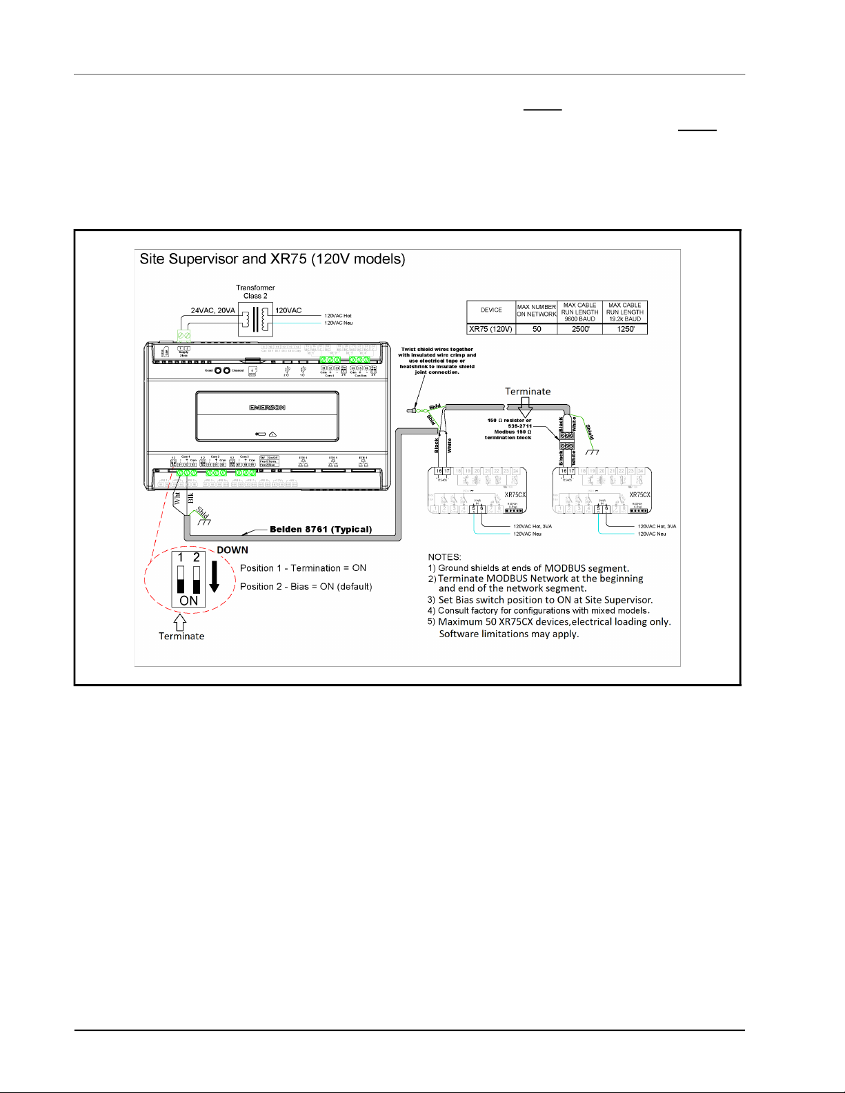
• Site Supervisor and XR75CX share the same MODBUS network polarity. Do not reverse polarity.
• Connect the shield wire to earth/chassis at the Site Supervisor end of the MODBUS network segment. Do not
con-
nect the shield wire to any connector on the Site Supervisor or XR75CX.
• For daisy-chain configurations, terminate devices at the beginning and the end of the network segment. Set the dip
switch position 1 and 2 to the ON position on Site Supervisor. For XR75CX end of network, terminate with a 150ohm resistor or 535-2711 termination block. All other devices in the network segment are not terminated
Figure 1-11
1-6 • Supervisory Controller 2.13 Installation and Operation Manual 026-1800 Rev 18
- Site Supervisor and XR75CX Wiring Layout

2 Basic Navigation
Log into Site Supervisor by clicking the Login icon in the
upper right part of the screen. For the Main Menu, click
the gear icon and the panel will slide open. Click the gear
icon again or to the right of the panel to close.
Six icons at the first row along the top of the screen are the
Back Arrow, Main Menu, Home, Refresh, Control
Inventory, and Schedule and Events. Refer to (Table 2-1)
for icon descriptions.
2.1 Menus and Submenus
1. Login - Logs you into the Supervisory controller.
Click and enter your username and password.
Once logged in, clicking Logout will log you
back out of the system. (You will automatically
be logged out of the system after a specified
period of idle time.)
Enter your Username/Password (default user/pass) and
click Login. Then update your password to the minimum
complexity requirements and click Save.
2. Home - Returns you to the set Home screen.
Click the Home icon to return to the Home screen
from anywhere in the system.
3. Summaries - Three submenus will display: Case
Defrost Schedule Summary, Network Summary,
and System Summary. Click each selection or
drop-down arrow (caret) to expand. Note that if
Peer Network is set up, the area controllers will
display under the Summaries menu under Area
Controllers.
• Case Defrost Schedule Summary- Takes you to
the Case Defrost Schedule Summary page where
edits to case defrost schedules can be managed.
• Network Summary - The network summary shows
the status of all network devices associated with
this Site Supervisor.
• Online - The device is online and communicating
normally
• Offline - The device is not communicating
(dropped off the network, has not been
commissioned, is not functional, or is not
powered up)
• Unknown - Unable to communicate with the
device
• This Supvr - Represents the current Supervisory
controller you are using; therefore, only one entry
in the list can show this status
• System Summary - Returns you to the home
screen
4. System Logs & Statistics - Contains controller
system information for technical personnel-level
users. Setpoint files can now be printed. Select
Setpoint Report. This report can be downloaded,
saved, or printed. Select Service Log for Clean
Out and Reset buttons. Clean Out will return the
controller to factory defaults. The controller will
reboot after a clean out with all programmed
applications, logs, and other data erased.
CAUTION: A clean out will erase all
programmed parameters from memory. The
Reset button only restarts and reboots the
controller.
5. Configure System- Contains navigation to
Logging Groups, Alarm Communications, File
Management & Licensing, General System
Properties, Manage Users (performs account
creation and role assignment for system users,
view, edit, and remove users) and My Profile
(allows you to create or edit your personal profile
page, create keyboard shortcuts, set localization
and engineering unit settings and more). Click
the drop-down arrow (caret) to expand.
• Logging Groups - Allows you to view log
parameters, add new logging groups, edit
parameters of existing logging groups, and delete
logging groups.
• Alarm Communications - View, edit, or delete
alarm notices from this page. Enable All to view all
notices in the system.
• File Management & Licensing - File Management
opens the File Management screen where you can
install and delete application description (ADF)
files, backup and restore system configuration,
install and delete floorplans, add/delete a license,
view application licenses in the system, add a
Feature Set, and upgrade firmware.
• General System Properties - Contains a
drop-down menu that includes these submenus:
COM Ports (COM Ports and baud rate settings),
Network Settings (Internet, subnet mask, DNS,
MAC Address, Email (SMTP), Text messaging
(SMS) and more), Localization (language and
engineering unit settings), and System Values
(general setup parameters, Web server and UI
setup).
Menus and Submenus Basic Navigation • 2-1
2.2 Overview
2.2.1 Conditional Visibility
Conditional Visibility allows points to be viewed that are
applicable to the defined view level (Basic or Advanced equivalent to “Full Options” in previous generation
controllers) for certain (not all) applications.
NOTE: The mobile Supervisory Controller
view does not support conditional visibility.
2.2.1.1 User View Details
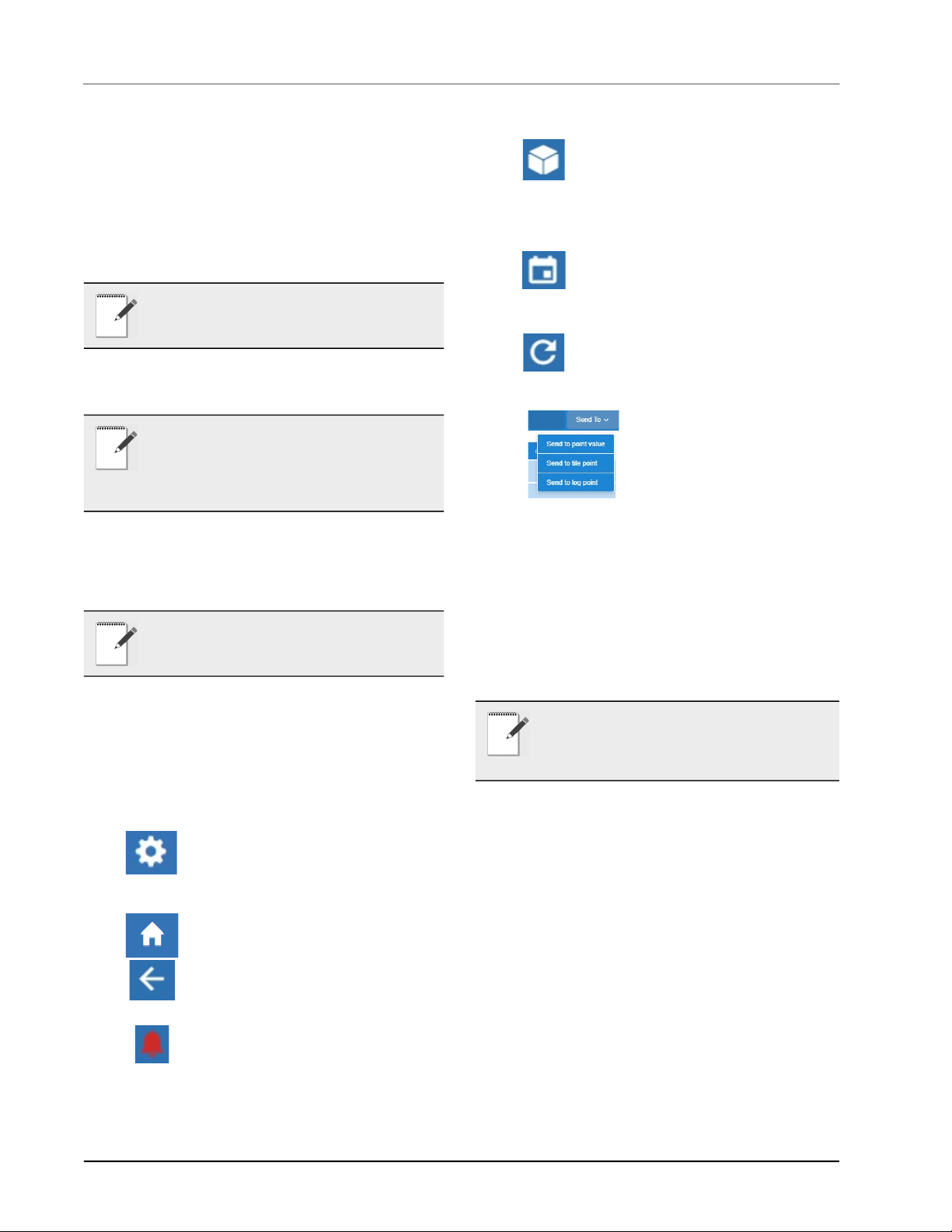
mark.
• Control Inventory (box) - Select this
box to access the Control Inventory
screen where applications can managed.
• Time Schedules (calendar) - Select to
access the Schedules and Events screen
where Schedules, Events, Inputs/Outputs,
Alarms, and System information is located.
• Refresh - Select to return to the Home
screen and log out.
NOTE: When you navigate to a specified
screen, you will see the points equal to or less
than your View Level available on the
Supervisory Controller’s rule. The basic user
level does not see the Advanced view level point.
Some screen information and contents are editable, which
when clicked can either display additional or related
information or move to another screen.
NOTE: The screen will only display applicable
points according to your view level and the
Supervisory Controller’s rules.
2.3 Basic Screen Elements
• Main display - This is the main section of the
screen, which contains and displays the content of
the chosen selection such as reports, device
information, configuration settings, and more.
• Main Menu (gear) - When clicked, the
Main Menu panel will slide open
containing the menus and submenus of
the controller.
• Home button - Returns you to the
default Home screen of the controller.
• Back button - This button will return
you to the previous screen. The Back
button is indicated by a left arrow icon.
• Active Alarms (red circle with excla-
mation mark) - When this icon is clicked,
the screen will display the
current active alarms. The number of alarms is
displayed in parentheses next to the exclamation
• Send To- Changes to multiple
applications at the same time
using the Send To button.
Changes to summary parameters, setpoints, log points, and
other parameters can now be
sent to multiple, user-selected
“like” applications. A single change or multiple
changes can be sent to all “like” applications using
the Save and Send To buttons, eliminating making
a change individually to each application one at a
time. For example, updates to a temperature setpoint can be sent with a single click to all controllers that you wish to update. The save confirmation
will confirm all changes made
NOTE: When some screen information and
contents are clicked, additional or related
information can be displayed or additional
screens accessed.
2.4 Language Settings
The default for the language selection is English (United
States). The system will store a setting for the preferred
system language (internal language code). This is used
when no authorized user is logged in. The default
language is used as a fall back when the currently active
preferred language doesn’t contain a translation for the
given label, prompt, or display text.
To change the language setting:
2-2 • Supervisory Controller 2.13 Installation and Operation Manual 026-1800 Rev 18
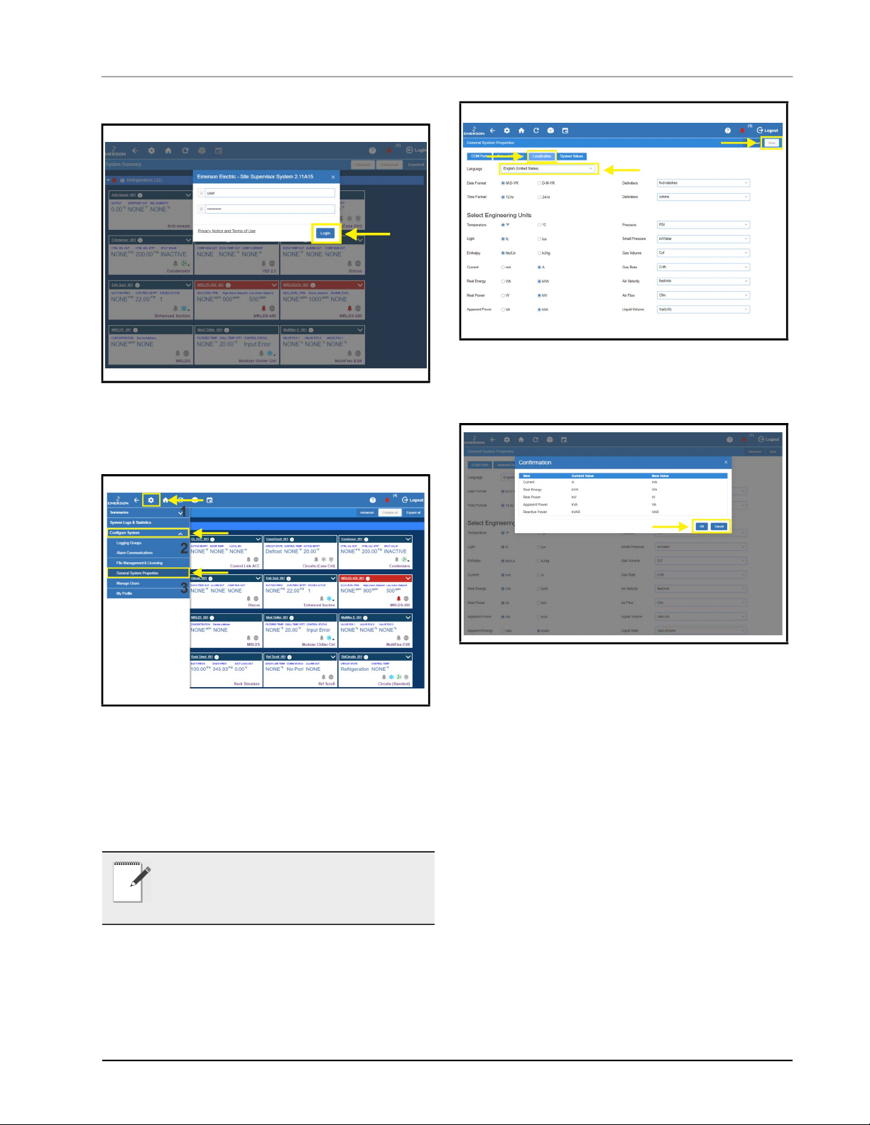
1. Log into the Site Supervisor.
Figure 2-1
- Logging In
2. Click the Main Menu icon.
3. Click Configure System> General System
Properties.
Figure 2-3 - Language Settings Set Up
7. The Confirmation pop-up box will appear on the
screen showing the summary of changes, click
OK or Cancel button.
Figure 2-2 - Language Settings Set Up
4. On the General System Properties page, click the
Localization tab.
5. Choose the preferred language on the Language
drop-down menu.
6. Click the Save button.
NOTE: English is the only language available.
Changing this setting will only change the
engineering units appropriate to the region
selected.
Figure 2-4 - Language Settings Set Up
2.5 Locating and Working With Applications
Applications in the controller are located on the Home
screen and from individual application screens and are
easy to find.
Each of the five categories can be seen on the Home
screen and if applications have been set up, they will
display under the category to which they have been
assigned. For example, in Figure 2-6 all of the five
categories are displayed with Refrigeration containing two
applications that have been set up. Choose an application
and the categories will then be displayed as icons across
the top that are easily accessible. Click the icons to see the
Locating and Working With Applications Basic Navigation • 2-3

applications.
conditions, which is an energy penalty and most often
goes undetected. Performance Meter gives the user a
graphical representation of performance data that shows
instances for performance that fall outside of the expected
normal performance band.
The Performance Meter tab will only be visible if licensed.
To display this tab, the user must click the Advanced
button, then click three-line menu as shown in Figure 2-7,
then click Performance.
Figure 2-5
The five categories are displayed on each application
screen. Click each icon to view applications that have been
set up for each category. For example, in Figure 6-2, the
Refrigeration icon has been clicked and the applications
for that category are displayed (Standard Circuits and
XR75CX). Click the application to go directly to that
screen.
Figure 2-6 - Application Screen Menus
- Home Screen Application Menus
2.6 Application Tabs
2.6.1 Performance Meter
Performance Meter gives the user a quick and simple
visual indication of system performance and early insight
that provides an opportunity to take corrective actions to
remedy conditions that may be reducing energy efficiency,
causing required service or ultimately leading to costly
failures. Performance Meter is a licensed application that
looks at the operational performance in relation to a
desired setpoint and calculates a “Figure of Merit” (FOM),
which takes into account deviations above and below
setpoints, but excluding defrosts. The overall FOM value
uses both high-temperature conditions that result in
product degradation as well as low-temperature
Figure 2-7 - Performance Meter Tab
2.6.2 Site Aggregation
Site Aggregation brings together status and data from
multiple controllers into one convenient view. You can
drag and drop the summary information into the order that
is most important to you. This can be your preferred view
when you log in with your user name. You can also create
custom categories, and drag and drop Summary Tiles into
categories and in the order you prefer. Categories appear
collapsed by default on the System Summary screen. (This
feature is supported by all models and not limited to
having a Site Aggregator license.)
To create a new custom category, click Edit on the
upper-right corner of the screen, then click the plus sign
that appears opposite the application name. An open box
(Category Name) will appear. Enter the name of your
custom category and click Save.
The Site Aggregator floor plan now links to E2 peer
application status and overrides. The Site Aggregator can
now be used with an E2 peer network to render E2 status
and overrides on floor plans.
2-4 • Supervisory Controller 2.13 Installation and Operation Manual 026-1800 Rev 18
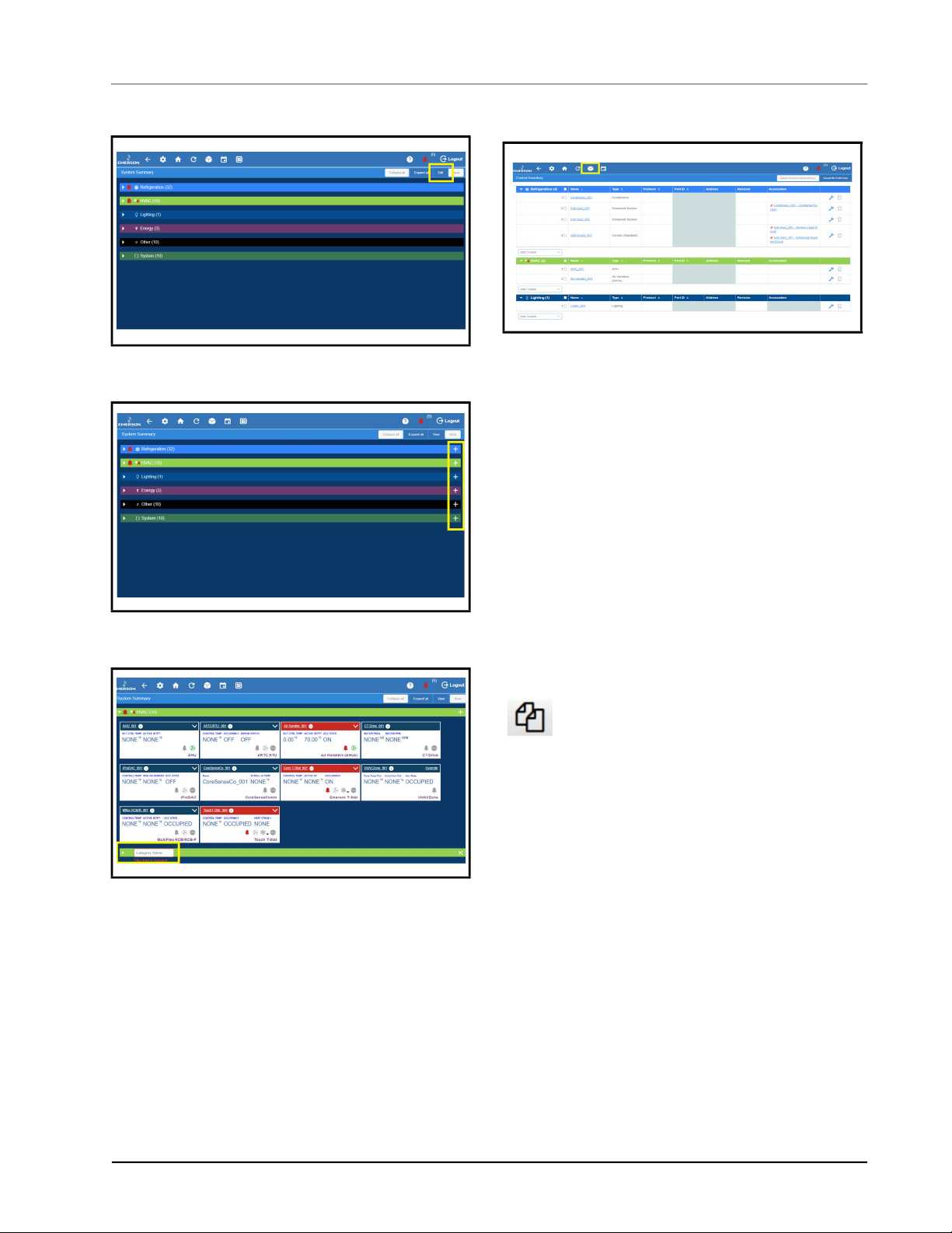
2.6.3 Control Inventory
Figure 2-8
Figure 2-9 - Click the Plus Sign
Figure 2-10 - Enter Category Name
- Click Edit
Figure 2-11 - Control Inventory Page
Control Inventory provides a centralized control list by
category. It allows you to view the network status of
controls, and perform the following functions: create and
duplicate one or more controls to a group quickly,
commission a device, associate controls to other controls,
edit the control name or commission information for
existing controls, and delete a control from existing
groups.
To duplicate an application, the appropriate user
privileges must be assigned. The user can specify the
number of duplicated instances for a device or application.
When a device or application is duplicated, the points
specified by the user or application type on the status tiles
is also duplicated. The name of each duplicated instance is
unique. The maximum total number of application
instances of a given type, including duplicated instances of
that type, will not exceed the license limit for that type.
Once the user has logged in, click the duplicate
button next to the application on the screen.
Select the count in Number of Duplicates.
2.6.3.1 Adding Applications
1. Add an application to your Supervisor by first
going to the Control Inventory page.
2. After logging in, click the Control Inventory icon
at the top of the screen.
3. From the Control Inventory screen, select an
application to add from the drop-down list at the
bottom of each category.
4. Fill in the fields and click Save.
5. Go back to the Home screen to verify the
application appears under the category.
Application Tabs Basic Navigation • 2-5
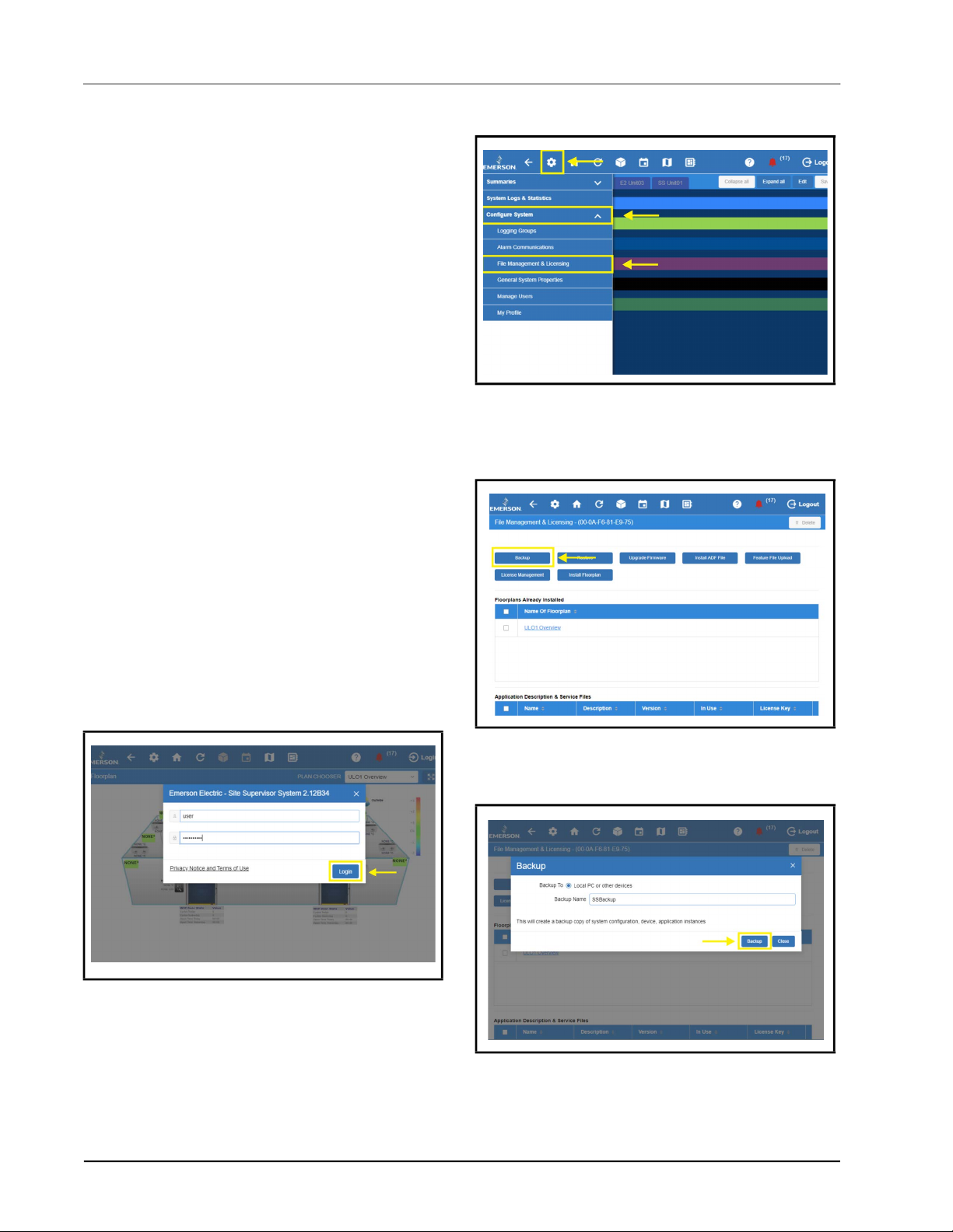
2.7 ADFs
An ADF is an Application Description File. ADFs allow a
particular device to communicate on the Supervisor. An
ADF is required before connecting a non-native device on
the Supervisor. The ADF is not automatically activated on
the Supervisor after installation. A license key is required
to enable specified instances of the application/device.
Contact your Sales representative or Customer Service to
obtain an ADF. The ADF can be uploaded on the
Supervisor using the File Management screen. A license
key is required to active the application after the ADF has
been uploaded. A license key can be obtained from
Technical Support with necessary approval. Email
ColdChain.TechnicalServices@Emerson.com with the
below information to generate the required license:
1. Name of the application/device
2. Supervisor MAC address and Model Type
3. Number of instance of the application
2.8 Creating a Backup and Restore
Figure 2-13 - File Management & Licensing
3. Click Backup and select where to save the
Backup (Local PC or Other Devices; SD Card)
and enter a name for the Backup.
2.8.1 Backup
Creating a backup is important if you are planning to
upgrade the Supervisor firmware. A Backup file does not
save properties such as Ethernet settings, loaded license
keys, firmware versions, alarm history, and logs.
1. Log into the Supervisor.
Figure 2-12
2. From the home page, click the gear icon and
- Logging In
choose Configure Settings> File Management &
Licensing.
Figure 2-14 - Click Backup
4. Click Backup to save. The Backup file location
will appear at the bottom of your browser.
Figure 2-15 - Backup File Location
2-6 • Supervisory Controller 2.13 Installation and Operation Manual 026-1800 Rev 18
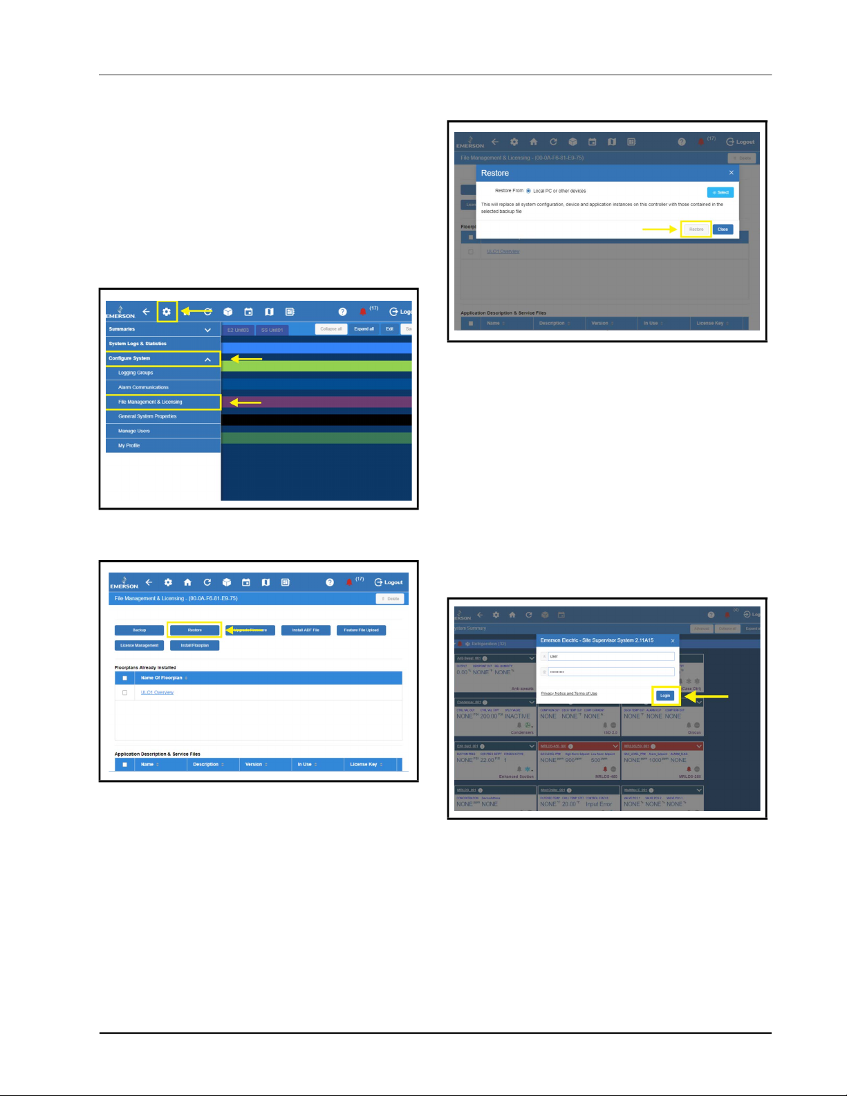
2.8.2 Restore
If the Backup file is available, a Restoration can be
performed. To successfully Restore, the Supervisor used to
create the Backup and the Supervisor to be restored should
be the same model. The ADF and license keys must be
complete on the Supervisor to be restored, matching the
applications configured on the Backup file.
1. From the home page, click the gear icon and
choose Configure Settings> File Management &
Licensing.
6. Click Restore.
Figure 2-18 - Restore
7. Click OK or Cancel on the confirmation window.
The Site Supervisor provides a restore notice when
restoring backup files. The notice will list any applications
that did not restore and the reason why, such as number
application limits exceeded, or missing ADF files.
2.9 Using the Help Menu
Figure 2-16
2. Click Restore.
Figure 2-17 - Restore
3. Select the source of the Backup file. Click Select.
4. Select the Backup file from its location.
5. Click Open.
- File Management & Licensing
This section contains instructions for using the help menu
on the Site Supervisor.
1. Log into the Site Supervisor and enter the
username and password.
Figure 2-19 - Logging into the Supervisory Controller
2. From anywhere in the controller, click the Help
Using the Help Menu Basic Navigation • 2-7
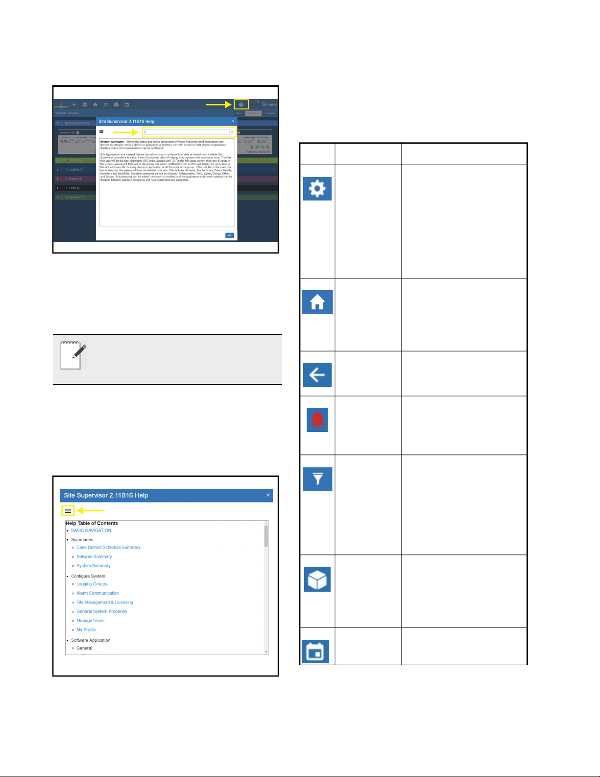
icon (question mark inside a circle):
2.10 Icons or Buttons Appearing on the Home Screen
Icon Function
Figure 2-20 - Click Help Icon for Page Help
3. A search field is available at the top of each help
page. Enter a keyword into the search field and
the help page you are currently viewing will be
searched for the keyword.
NOTE: The HELP menu is context sensitive
and will display information about the
function, application, or device the user is
viewing.
4. Click the Main Menu button (three horizontal
lines) to show the complete menu. It will provide
links to the complete help menu with links per
topic on the table of contents.
5. Search key words on the search box to narrow
down topics to search.
Main Menu
Gear Icon
Found at the top left-hand
side of the page. When the
main menu gear icon is
clicked, the main menu
panel will slide open
containing the menus and
submenus of the
controller.
Home Opens the main menu
panel when clicked. The
main menu panel contains
menus and submenus of
the controller.
Back Arrow The Back button will
return you to the previous
screen.
Active
Alarms
When the Active Alarm
icon is clicked, the screen
will display the current
active alarms.
Filter Clicking the Filter icon
opens the Filter Alarms
screen which allows you
to choose or filter the type
of alarm you want to see
on your Active Alarms
screen.
Figure 2-21
- Click Help Icon for Page Help
Control
Inventory
Click to manage the
system-wide inventory of
applications. Edit, delete,
and add applications from
this screen.
Time
Schedules
Table 2-1 - Top Screen Icons and Buttons
Click to add and edit
schedules and events.
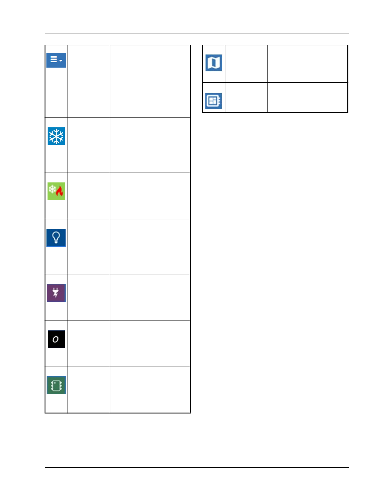
Screen Dropdown Menu
The screen drop-down
menu is activated when
the current screen is
active/online. This menu
contains other options
such as Download,
E-mail, Print, and View
History.
Refrigeration Displays on Home screen
and application screens.
Shows all applications in
the controller that are
categorized under
Refrigeration.
HVAC Displays on Home screen
and application screens.
Shows all applications in
the controller that are
categorized under HVAC.
Lighting Displays on Home screen
and application screens.
Shows all applications in
the controller that are
categorized under
Lighting.
Floor Plan Click to manage the
floorplans installed on
your controller (if
applicable)
Physical I/O
Status
Click to view and
configure all I/O boards
on your controller.
Table 2-1 - Top Screen Icons and Buttons
Energy Displays on Home screen
and application screens.
Shows all applications in
the controller that are
categorized under Energy.
Other Displays on Home screen
and application screens.
Shows all applications in
the controller that are
categorized under Other.
System Displays on Home screen
and application screens.
Shows all applications in
the controller that are
categorized under System.
Table 2-1 - Top Screen Icons and Buttons
Icons or Buttons Appearing on the Home Screen Basic Navigation • 2-9

3 Alarm
Configuration
Alarms in the supervisory controller can be generated
from different sources including external networked
devices, applications, value-added applications, and subsystems. Alarm configuration, transmission, and history
settings can be defined by the user.
1. Log in to the Site Supervisor by clicking Login
on the Main Menu, located on upper right side of
the screen and enter your username/password.
to access the device status page.
Figure 7-3 - XR75CX Under Refrigeration
4. On the drop-down menu on the upper right of the
screen, click Edit and Advanced to access
configuration properties and alarms for the
XR75CX 5.6 device.
Figure 3-1
Figure 3-2 - Accessing Site Summary
- Site Supervisor Login
2. From the Home screen, navigate to Summaries>
System Summary.
3. In this example, alarm configuration for
XR75CX 5.6 controller is used. Select the
XR75CX 5.6 device on the Site Summary screen
Figure 3-4 - Accessing the Configuration Properties of
XR75CX 5.6
Click each tab to see the XR75CX parameters:
Figure 3-5 - XR75CX 5.6 Tabs
In the Status tab, selecting properties for the Status tab list
is unlimited. The top 10 properties shown on the System
Summary tile will appear with a different color from the
rest of the items on the list. Properties can be dragged and
dropped into the list and color designations can be
changed. Note that under the Status tab on any device
application page, the wrench icon can be clicked for
customizing the summary tile information.
Alarm Configuration • 3-1
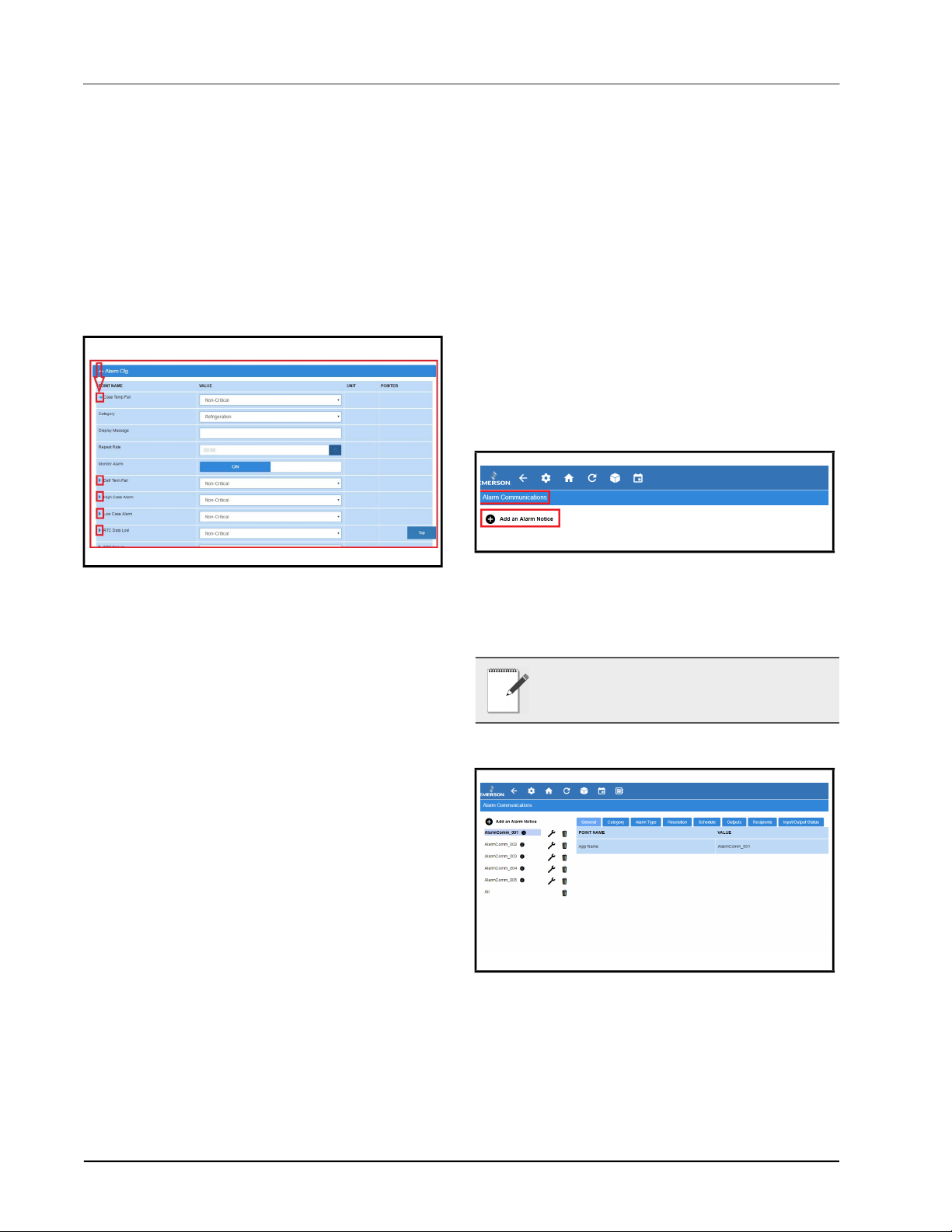
Users who are logged in with System Administrator
privileges can overwrite the default setting on the selected
point's section that will be synchronized with the tiles on
the System Summary page. New category icons are
located across the top and when clicked will go to those
application pages.
will go to the call center for monitoring) or OFF
(for no call center monitoring).
3. Once configurations have been set, select Save
on the upper right side of the screen.
3.2 Alarm
3.1 Alarm Configuration
1. For alarm configurations, scroll down to the
Alarm Cfg parameter section.
Figure 3-6
- Configuring Alarms
2. On the Alarm Cfg parameter section, click the
arrow beside the name of the parameter to
configure other settings for alarming.
• Alarm descriptions can be overridden from this
page. Enter the name of each application alarm you
wish to appear in the alarm log. If no name has been
entered, the default alarm message will display in
the alarm log.
• Each alarm type (urgency level) can be categorized
as Non-Critical, Critical, or Notice (the least
urgent).
• Each alarm category (where it is categorized in the
supervisory controller) can be set under the
Category field: Refrigeration, HVAC, Lighting,
Energy, or Other.
• Set the repeat time for the alarm on the Repeat
Rate field, which is the time the advisory is next
scheduled to repeat if not acknowledged. A
repeated advisory will re-queue to the system as if it
had just been generated. However, it will not create
a new instance; it will only update the existing
instance with the next repeat time. All other
processing and propagation will act as a new
instance of an advisory.
• Set the Monitor Alarm field to ON (if the alarm
Communications
Setting
Configure alarm communications setting on Alarm
Communications screen for SMTP (emailing), and texting
alarms.
1.From the Home screen, navigate to Main Menu>
Configure System> Alarm Communications and click Add
an Alarm Notice at the top.
Figure 3-7 - Alarm Comm Page - Create New Alarm Notice
The Alarm Communications screen creates a custom
notification of alarm conditions or set default values for as
many as 20 notifications for each device.
NOTE: This screen will not be accessible if you
are not logged into the controller.
Figure 3-8
- Alarm Communications Tabs
3-2 • Supervisory Controller 2.13 Installation and Operation Manual 026-1800 Rev 18
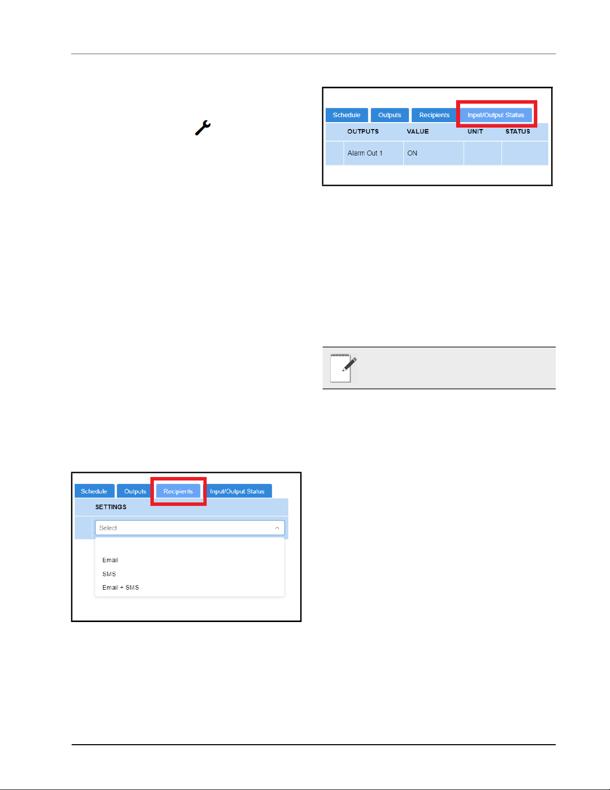
When creating a new alarm notice, there are three steps
on the Alarm Communications page:
Step 1: Enter a unique name
• Click the wrench icon beside the alarm
notice to view the tabs then click Edit located on
the upper right side of the screen. Name the alarm
notice by entering a unique identifier under App
Name in the General tab.
Step 2: Select all of the desired options under each
tab
• Category – Select ON or OFF for the following
category menu options: Refrigeration, HVAC,
Lighting, Energy, Other, System, and ProAct.
• Alarm type – Select ON or OFF for the following
alarm-type menu options: Critical, Non-Critical,
and Notice (least urgent).
• Resolution – Select how the alarm notice should be
handled. Select ON or OFF for the following
resolution menu options: Acknowledge, Reset to
Normal, and Return to Normal.
• Schedule – Select an option from the drop-down
list.
• Outputs - The output menu options are the
following: Alarm Out 1 Config (Audio), Alarm Out
2 Config (Visual), Alarm Out 3 Config (3rd Party
A), and Alarm Out 4 Config (3rd Party B). Select
the desired value for each output menu option: Not
enabled, Active until acknowledged, Active until
muted, or Timed one-shot pulse.
Figure 3-10 - Input/Output Status Tab
• Input/Output Status - The Input/Output Status tab of
every application will appear as a new tab on the
details summary screen to view all the necessary
properties to troubleshoot any issues more
effectively.
Step 3: Click Save
• Click Save in the upper right side of the screen.
When all fields for the new alarm notice are
completed, a confirmation pop-up screen will
appear.
NOTE: Only 20 notices can be created. To edit
the current notice, a specific role is required in
this function.
Figure 3-9
- Recipients Tab
• Recipients - For each user, select how the alarm
will be communicated. The first column shows the
list of users while the second column shows the
combo box. The combo box will have 4 selections:
Disabled (blank), Email, SMS (Text), and Email +
SMS. The default value will be “Disabled”.
Alarm Communications Setting Alarm Configuration • 3-3
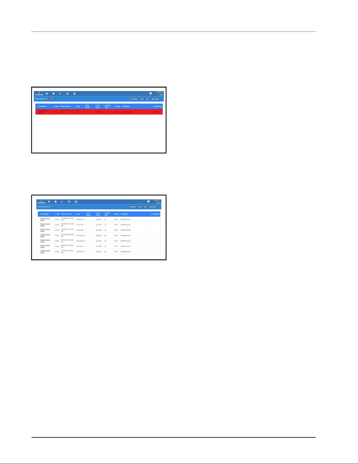
3.3 Alarm Log and View History
Select the Active Alarms icon to open the Alarm Log
screen and view the list of active alarms in the system:
Figure 3-11
The alarm name appearing in the Description column is
the default name or custom name assigned to the alarm.
Click View History to see the collection of alarms that
have been resolved.
Figure 3-12 - Alarm History
Active alarms also appear as default on the Home screen.
- Alarm Log
3-4 • Supervisory Controller 2.13 Installation and Operation Manual 026-1800 Rev 18

3.4 Temperature Differential Alarms
Once the newly requested points are correctly set, alarms are generated when the real values do not meet the TD setpoint.
Property Details
Name
Value Range Default Log
Visibility
Differential
Temperature
Selection
Heat Alarm Diff
(Differential)
Cool Alarm Diff
(Differential)
Differential Alarm Notice; Critical;
Table 3-1
The four points added to the AHU application are to ensure that two kinds of alarms are generated respectively, and they
are listed in the table below:
Alarms by Heat Alarm Diff The supply temperature value is not higher than the user-specified sensor’s value by at least
Alarms by Cool Alarm Diff The supply temperature value is not lower than the user-specified sensor’s value by at least
- Alarm Properties
Alarms Type
(Same alarm short
description)
Space, Zone, Mixed,
Return or None.
0~54.00DDF 18.00DDF N/A Refer to the interpretation above.
0~54.00DDF 18.00DDF N/A Refer to the interpretation above.
Non-critical; Disable
the Heat Alarm Diff amount.
If the supply temp value is higher than the user-specified sensor’s value by the Heat Alarm
Diff amount or more, the previously generated alarm returns to normal.
the Cool Alarm Diff amount.
If the supply temp value is lower than the user-specified sensor’s value by the Cool Alarm
Diff amount or more, the previously generated alarm returns to normal.
N/A N/A When the point is set as Space, Zone,
Mixed or Return respectively, the Heat
Alarm Diff, Cool Alarm and Diff Alarm
properties are visible.
Notice N/A Refer to the interpretation above.
Conditions Alarms Generate
Table 3-2
For the CC T-Stats device, three properties need to be added in the Alarms tab, and they are listed in the table below:
Table 3-3
Temperature Differential Alarms Alarm Configuration • 3-5
- Alarms Generated from AHU Application
Property Details
Name
Value Range Default Log
Diff Alarm Notice; Critical; Non-
critical; Disable
Heat Alarm Diff 0~54.00DDF 18.00DDF N/A Refer to the interpretation above.
Cool Alarm Diff 0~54.00DDF 18.00DDF N/A Refer to the interpretation above.
- Alarm Properties in Emerson T-Stats
Disable N/A When this property is set as Disable,
below two properties will not be visible.
Visibility

The points added to the Emerson T-Stat devices are to ensure that two kinds of TD alarms are generated respectively, and
they are listed in the table below:
Alarms Type
(Same alarm short
Conditions Alarms Generate
description)
Alarms by Heat Alarm Diff When the system goes to heating control, an alarm is generated when the Supply Air
Temp value is not higher than the Space Temp value by at least the Heat Alarm Diff
amount.
If the Supply Air Temp value is higher than the space temp value by the Heat Alarm Diff
amount or more, then the previously generated alarm returns to normal.
About the Space Temp Value:
1. System uses the Rem Space Temp value as the space temp value if Remote Spc
Temp is set as Yes.
4. System uses the value from a physical space temp probe as the space temp if such
a probe is installed.
5. Remote Spc Temp is set as No
Alarms by Cool Alarm Diff When the system goes to cooling control, an alarm is generated when the Supply Air
Temp value is not lower than the Space Temp value by at least the Cool Alarm Diff
amount.
If the Supply Air Temp value is lower than the Space Temp value by the Cool Alarm
Diff amount or more, then the previously generated alarm returns to normal.
The rules that system chooses the Space Temp value is the same as those for alarms by
Heat Alarms Diff.
Table 3-4
- Alarms Generated from Emerson T-Stat
3-6 • Supervisory Controller 2.13 Installation and Operation Manual 026-1800 Rev 18

3.5 Lighting Cycle Alarms
Once the newly requested points are correctly set, alarms are generated when the real values exceed the set ones. For the
lighting control application, three properties need to be added in the Alarms tab, and they are listed in the table below:
Name Property Details Visibility
Max Excessive Light Cycles There are four types, critical, noncritical
and notice, Disable (by default).
Lts Cycle Max The value can be set in the range of
0~999.
This property is not visible to users
when Disable is set for Lts Cycle Type.
Table 3-5
The two points added to the lighting control application are to ensure that the lights are operated correctly in a single day.
Once the real value of light cycle exceeds the max cycle set in Table 3-5, alarms are created. The starting time for
calculating the lighting cycles is set at midnight and ends after 24 hours, which is clearly operated in the background.
For the lighting control application, another two properties needs to be added in the Alarms tab, and they are listed in the
table below:
Table 3-6
An alarm is generated if the lights are on for more than the Lts On Lng Del value set by users in Table 3-6.
- Alarm Properties
Name Property Details Visibility
Lts On Too Long There are four types, critical, noncritical
and notice, Disable (by default).
Lts On Lng Del The value can be set in the range of
0~999.
- Alarm Properties Added in Lighting Control Application
This property is not visible to users
when Disable is set for Lts on lng Type.
N/A
3.6 Smart Alarming
Smart Alarm is an alarm that gives additional information about alarms and provides suggested corrective actions. It
creates conditional statements that will compare conditions and generates a notification when these conditions are met.
These alarms use all the current transmission methods – SMS, email and MSSR – and include information such as
explanations, relevant data, brief graphs, possible causes and suggested actions. Some specific alarms are temperature
differential, excessive cycling and sensor data.
3.6.1 Accessing Smart Alarms
1. Log into the Supervisor with a
technician or administrator-privileged user
credentials.
2. Install the .adf file of a specific Smart Alarm type
in the Install Application Description File screen.
(An ADF or Application Description File allows
a particular device to communicate on the
Supervisor. An ADF is required before
connecting a non-native device on the
Supervisor. The ADF can be uploaded on the
Supervisor using the File Management screen. A
license key is required to active the application
after the ADF has been uploaded.)
3. Install the license of the Smart Alarming feature
in the Licensing screen.
4. To add a Smart Alarm application instance in the
Control Programming screen, select Control
Programming from the Main Menu, select Smart
Alarm from the drop-down list under Control/
Application Type drop-down and enter the
number of applications in the Quantity field.
5. Configure the Smart Alarm application instance
in the Device Details screen. Select or enter the
correct values in Name, Long Name, Category,
and Related Application/Devices parameters.
Lighting Cycle Alarms Alarm Configuration • 3-7

Related Application/Devices lists all applications or
devices that can be associated with the Smart Alarm. If
one or multiple applications or devices are selected, they
will work with the Smart Alarm together.
• In View Mode, the selected applications or devices
will display as links. If a link is clicked, it will open
the Details screen of the selected application or
device.
• In Edit Mode, these related applications or devices
will display as checkboxes.
6. When the trigger conditions of the Smart Alarm
are complete, a Smart Alarm will be generated
and displayed in the Active Alarms screen.
Active Alarms Screen:
• If alarms display as a table in the Active Alarms
screen, a light bulb icon will appear beside the
Smart Alarm’s Description column..
• If alarms display as a card in the Active Alarms
screen, a light bulb icon will appear at the top right
corner of the card; its color will change depending
on the alarm type.
History Alarms Screen:
For Smart Alarm:
• Four properties - Explanation, Possible Cause,
Suggesting Actions, and User Defined Message
display at the top of the Details list.
• Originator, Report Value, and Limit Value
properties may have multiple items.
• Report Value and Limit Value properties are
always displayed.
• The View Graph button appears on the right side of
the Details list header. The log graph of the
current Smart Alarm will appear if the View Graph
button is clicked.
For devices with small screens, the Details list of the
Smart Alarm will be compressed. If there is not enough
space to show the graph, use the horizontal scrollbar to
adjust.
• If alarms display as a table in the History Alarms
screen, a light bulb icon will appear beside the
Smart Alarm’s description column.
• If alarms display as a card in the History Alarms
screen, a light bulb icon will appear the top right of
corner of the card.
Note: The alarm indicators (icon and border color) in the
Main Header, Main Menu, and Site Summary screens are
always displayed even when there are no Smart Alarms in
the system.
In the Filter Alarms screen, the Smart Alarm
checkbox can be selected under Category to filter Smart
Alarms. The Smart Alarm checkbox is always displayed
when there are no Smart Alarms in the system.
7. The Critical Alarm screen will display if a Smart
Alarm in the Active Alarms or History Alarms
screen is selected. A light bulb icon will appear
beside the dialog header. There are three actions
for Smart Alarm: Acknowledge, Reset, and
Mute - their functionalities are similar to normal
alarms. If the user is not logged in or has not
configured the History Alarms screen, the
Actions area will be hidden.
3-8 • Supervisory Controller 2.13 Installation and Operation Manual 026-1800 Rev 18

3.7 Peer Alarming
Peer Alarming enables both the E2 and the Supervisory Controller to transmit the alarms to the alarm annunciator
controller in a peer group. The general operations for the integrated alarms can then be handled in one controller making it
more convenient for users to manage and deal with all the alarms in only one annunciator in one peer group. For more
information about Peer to Peer setup, go to Appendix E: Peer to Peer Network Setup for Mixed Sites (Two Supervi-
sors and One E2).
3.8 Generic Alarms
Generic Alarms enable users to custom-assign alarms in the controller for any analog or digital output and allows users to
set custom high-low alarm setpoints for both occupied and unoccupied building states. Up to 10 generic alarms can be
created for each application. Each alarm is configurable with options of Disabled, Notice, Non-Critical, or Critical. For
each alarm the standard Advisory parameters are also available. Generic Alarms must first be enabled in the General
System Properties -> System Values tab. To set up Generic Alarming in any application, go to the application’s Generic
Alarms tab. To add a Generic Alarm, select an output from the drop-down list and then click + Add Generic Alarm. Each
added alarm will be named Generic Alarm, enumerated from 1-10, and followed by the name of the output to which it is
assigned. Each alarm’s parameters will be hidden beneath the first row. Click the chevron to access all the alarm
parameters. The alarm will be generated when the value of the output exceeds the setpoint after the programmed alarm
delay is satisfied. Removing a Generic Alarm can be accomplished by clicking the X at the end of its first row.
3.9 Alarm Types
For a list of alarms in the Supervisor, please see Appendix A - Alarm Advisories
Peer Alarming Alarm Configuration • 3-9

4 Hardware
Overview
4.2 Technical Specifications
Site Supervisor is a Supervisory Controller system that
combines energy management with the ability to monitor
various facility systems and provide alerts when there are
issues that need attention. This system provides HVAC
control, Refrigeration System Monitoring and Control, as
well as Lighting Control. In addition, the Supervisory
Controller can monitor and report energy consumption and
take action to reduce the energy demand during peak
periods. This can have a direct impact on utility bills by
reducing total energy costs. Supervisory Controllers
ensure that the HVAC and lighting systems are on and off
at the appropriate times. This ability to monitor store
conditions can potentially minimize energy consumption.
4.1 Ordering information
860-1200 Site Supervisor
SF
860-1220 Site Supervisor
RX
860-1225 Site Supervisor
RXe
860-1240 Site Supervisor
BX
Small Format
Refrigeration
Controller 300
Level
Refrigeration
Controller 400
Level
Building
Controller 300
Level
Operating
Temperature
Relative
Humidity
Enclosure Rating UL 94 V-0
Dimensions 110mm x 183mm
Power In 24VAC 50/60 Hz +/- 10% 20VA
1 Can Bus Expansion Module Connections
4 RS485 ports MODBUS Com Ports 1, 2, 3,
3 Ethernet ports Ports 1, 1, 0
Analog Inputs 8
2 USB Ports 1, 2
MicroSD 1
Digital Inputs 4
Relay Outputs 4
Agency
Approvals
-40°F to 149°F
(-40°C to 65°C)
20-85% RH
non-condensing
5/16”
4
(
24VDC +/- 10% .8A
Only
and 4
ULE211299, CE
x 7
3/16”
)
860-1245 Site Supervisor
BXe
860-1260 Site Supervisor
CX
860-1265 Site Supervisor
CXe
Table 4-1
Note: For complete product part numbers and accessory
ordering information, contact your Emerson Sales
representative or Customer Service.
Ordering information Hardware Overview • 4-1
- Site Supervisor Ordering Part Numbers
Building
Controller 400
Level
Convenience Store
Controller 300
Level
Convenience Store
Controller 400
Level
Table 4-2
- Site Supervisor Specifications

4.3 Housing Dimensions and Mounting
Figure 4-1
Mounting
The Site Supervisor can be mounted to standard 35mm
DIN rail using the orange mountain clips.
It can also be screwed to a back plate by pulling the four
(4) orange mounting tabs out until they lock, which will
expose mounting holes.
- Site Supervisor Housing Dimensions and
4-2 • Supervisory Controller 2.13 Installation and Operation Manual 026-1800 Rev 18

4.4 Wiring Diagrams
Figure 4-2 - Site Supervisor Controller Wiring Diagram
Wiring Diagrams Hardware Overview • 4-3

Figure 4-3 - Site Supervisor Detail
4-4 • Supervisory Controller 2.13 Installation and Operation Manual 026-1800 Rev 18

4.5 Device Wiring
See Section 6, Wiring Examples for typical power and COM wiring.
4.6 Site Supervisor Power, Serial, and IO Positions
Figure 4-4
- Site Supervisor Power, Serial, and IO Positions
4.6.1 Termination Jumpers
Depending on the orientation of the board, the termination jumpers are set in the down position (always toward the board
- ON) for termination and up (always away from the board - OFF) for no termination. Position 1 = Termination and
Position 2 = Bias. Refer to the enclosure diagram for termination jumper direction.
Figure 4-5 - Termination Jumper/Dip Switch Positions
Device Wiring Hardware Overview • 4-5

4.6.2 Using a DC Volt Meter to
Check Termination and Bias
Unplug connector from the Site Supervisor Serial port and
make DC voltage measurements on the Serial port pins.
Place the meter common probe on the Serial Comm pin
and measure voltage on the Serial port “+” pin and the
Serial port “-” pin. See the table below for expected
voltages
Table 4-3 - Termination and Bias Voltages
*Note that for both Termination and Bias OFF, the
voltage on both pins are undetermined but typically equal
and near 2.4Vdc
.
Term Bias Serial + Serial -
OFF ON 5Vdc 0Vdc
ON ON 2.7Vdc 2.3Vdc
OFF OFF *2.4Vdc *2.4Vdc
.
4.6.3 Removing The SD Card
If present, the user can manage the SD card or USB drive
in order to upgrade controller firmware, set the Ethernet
TCP/IP configuration, and read the Ethernet TCP/IP
settings. The SD card must be inserted in the SD socket.
To remove the SD card safely from the Site Supervisor
without shutting down, click Safely Remove under File
Management and remove the SD card from the socket.
4.6.4 LEDs
Figure 4-8 - LEDs on Front Enclosure
STATE DESCRIPTION
Solid red Starting up
Flashing red - 1 Hz Loading OS/Application
Solid green Running - Normal Status
Flashing red - 2 Hz Failure to load
Table 4-4 - LED States and Definitions
Figure 4-6 - Safely Remove the SD Card
Figure 4-7 - Micro SD Card Slot
CAUTION! DO NOT remove the cover.
Removing the cover will void the warranty.
4-6 • Supervisory Controller 2.13 Installation and Operation Manual 026-1800 Rev 18

4.6.5 Dip Switch Termination and Biasing
Figure 4-9
The termination and biasing dip switches are located to the left of their respective communications port connectors. The
switches are oriented such that switch down is ON for the function. The dip switches are of the “piano key” type and must
be moved up and down when they are viewed as shown above.
The termination dip switch must be ON (down) when the Site Supervisor is the first or last device on the RS485
network, most easily recognized by having only 1 Belden style cable attached to the connector.
What is biasing?
The transmission line into the RS-485 serial port enters an indeterminate state when it is not being transmitted to. This
indeterminate state can cause the receivers to receive invalid data bits from the noise picked up on the cable.* To prevent
this, set the bias dip switch to ON (down) which will add the appropriate amount of resistance.
*Source: National Instruments Serial Troubleshooting Wizard
or panel (if installed) so that ample light and line of sight can be obtained during this procedure. An example of a
broken dip switch can be seen below.
- Dip Switch Configuration
NOTE: The switches are somewhat fragile and care should be taken when switching them from ON to OFF
or vice versa. It is also likely that a small control screwdriver needs to be used because of space and clearance
between the COM port connectors, and you must ensure that power to the controller is secured prior to
changing the switch position(s). It is highly recommended that the controller be removed from its enclosure
Figure 4-10
Site Supervisor Power, Serial, and IO Positions Hardware Overview • 4-7
- Broken Dip Switch

4.7 Wiring Terminal Detail
Figure 4-11
- Site Supervisor Wiring Terminal Detail
4.8 Digital Inputs
Figure 4-12 - Digital Inputs
• Can read both dry and wet (24VAC) contact
closures
• Dry contact wire to DI 1 – DI 4 and Cdry
• Wet (live) contact wire to DI 1 – DI 4 and Cac
• Can read pulses up to 10Hz
4.9 Relay Outputs
Figure 4-13 - Relay Outputs
• Relays are Form C rated 5A at 120V/240VAC
• General Purpose
4-8 • Supervisory Controller 2.13 Installation and Operation Manual 026-1800 Rev 18

• 100K Cycles
NOTE: General purpose relays are
cost-effective 5-15 Amp switching devices used
in a wide variety of applications.
Features:
• Electrical loads of 5 to 15 Amps.
• Contact configurations through 3PDT.
• Coils molded in polyester for environmental
protection.
• Pin 17 is common for relays 1 & 2
• Pin 24 is common for relays 3 & 4
• Relay 1 (RL 1) - Pin 15 NC / Pin 16 NO
• Relay 2 (RL 2) - Pin 18 NC / Pin 19 NO
• Relay 3 (RL 3) - Pin 20 NC / Pin 21 NO
• Relay 4 (RL 4) - Pin 22 NC / Pin 23 NO
4.10 Analog Inputs
Figure 4-14 - Analog Inputs
• Supports 0-10VDC, 0-1 DC, 0-5VDC, 2-20mA, 4-20mA, Emerson NTC temperature and dry contact digital input.
• Supports engineering units for temperature, pressure, humidity, light level and generic percentage.
• When wiring transducers or amplifiers (for example, outdoor light level) the odd numbered terminal is the + or
signal and the even numbered terminal is the – or common.
• Provides (2) 12VDC (160mA) and (2) 5VDC (40mA) power supply terminals for humidity sensors, pressure
transducers, and more.
Type Ratings Terminal
Relay 1 (N.O. & N.C.) 5A, 125/240 VAC, General Purpose, 100K cycles;
4FLA/4LRA, 250VAC, Motor Load, 100K cycles
Relay 2 (N.O. & N.C.) 5A, 125/240 VAC, General Purpose, 100K cycles;
4FLA/4LRA, 250VAC, Motor Load, 100K cycles
Relay 3 (N.O. & N.C.) 5A, 125/240 VAC, General Purpose, 100K cycles;
4FLA/4LRA, 250VAC, Motor Load, 100K cycles
Relay 4 (N.O. & N.C.) 5A, 125/240 VAC, General Purpose, 100K cycles;
4FLA/4LRA, 250VAC, Motor Load, 100K cycles
J5-2, J5-3, J5-4 (Base Board)
J5-1, J5-2, J6-6 (Base Board)
J6-1, J6-4, J6-5 (Base Board)
J6-1, J6-2, J6-3 (Base Board)
Table 4-5- UL Relay Ratings
Analog Inputs Hardware Overview • 4-9

4.11 Serial Connections
Figure 4-15
Supervisory Controllers are equipped with four (4) RS485 serial Com ports and one (1) Can Bus port.
• Com ports 1-4 support MODBUS and Emerson (CPC) IO Net.
• Com ports 1-4 support 9600, 19200, 38400, 57600, and 115200 baud connection speeds.
• The Can Bus port is for expansion I/O such as the IPX206D and IPX225D.
• Com ports 1-4 wiring polarity:
- Serial Connections
• Same polarity – XR75CX, Emerson Energy Meter.
• Opposite polarity – Emerson T-Stat, Control Link ACC, MRLDS, all I/O boards including MultiFlex and
legacy boards.
4.12 Firmware Upgrade
When a USB device containing Supervisory Controller firmware package is plugged into the Supervisory Controller
device, the system will automatically detect it. Once the user reaches the firmware updating page, the firmware from
USB disk option can be selected. The firmware updating process includes three steps:
• Select: Select a firmware package from the USB and conduct a legitimacy check.
• Transfer: Transfer the selected firmware from the USB to the Supervisory Controller.
• Apply: Upgrade the transferred firmware to the targeted Supervisory Controller.
A processing bar will appear to inform the user of the real-time processing during transferring and application.
The system will reboot automatically when the application process is complete.
4-10 • Supervisory Controller 2.13 Installation and Operation Manual 026-1800 Rev 18

4.12.1 Firmware Update - Remote Access
1. Download the latest firmware update file (for example, “SS_2.0XF01_Firmware_Update) to a location on your
PC.
2. Connect a standard Ethernet cable from the Supervisory Controller (ETH 0 port) to a router and enter the
Supervisory Controller IP address into a browser.
3. Login and select Configure System>File Management & Licensing from the main menu
4. Before proceeding with the firmware update, click Backup (to back up configuration files).
5. Once the backup is complete, click Upgrade Firmware and click Select. Browse and locate the latest firmware
update file. Select the file and click Open or double-click the file to load.
6. A Loading file message will appear (wait for several seconds). Once loaded, the Revision and File Size will
display.
7. Click Transfer. A progress bar will appear with the percentage complete.
Figure 4-16
8. Click Apply. A progress bar will appear with the percentage complete. The system will reboot and restart
9. The new firmware version number will appear in the lower right corner of the screen.
Note that all setpoints and configuration will remain the same. If there are discrepancies, use the backup file to
restore previous settings.
- Upgrade Firmware - Remote Access
automatically when the upgrade is complete.
4.12.2 Firmware Update - USB Drive
1. Copy the latest firmware update file (for example, “SS_2.02F08_Firmware_Update) to the root folder of a USB
thumb drive (the USB thumb drive must be format FAT16).
2. Connect a standard Ethernet cable from the Supervisory Controller (ETH 0 port) to a router and enter the
Supervisory Controller IP address into a browser.
3. Login and select Configure System>File Management & Licensing from the main menu .
4. Click Upgrade Firmware then select USB and choose the path.
5. Click Transfer. A progress bar will appear with the percentage complete.
6. Click Apply. A progress bar will appear with the percentage complete. The system will reboot and restart
automatically when the upgrade is complete.
Firmware Upgrade Hardware Overview • 4-11

Figure 4-17 - Upgrade Firmware - USB Drive
4-12 • Supervisory Controller 2.13 Installation and Operation Manual 026-1800 Rev 18

4.13 Uploading Setpoint Files to Supervisory Controller
8. Copy the set point file to a USB thumb drive.
9. Plug the USB thumb drive into the Supervisory Controller.
10. Login and select Configure System>File Management & Licensing from the main menu .
11. Select Restore then select the USB.
12. Click the radial button for the setpoint file.
13. Select Restore.
Figure 4-18
- Upload Setpoint File to the Supervisory Controller
Uploading Setpoint Files to Supervisory Controller Hardware Overview • 4-13

5 RS485 I/O
Network Boards
and Peripherals
Site Supervisor has up to two RS485 network ports, each
of which may be configured as an I/O network or
MODBUS port.
5.1 The I/O Network
Most of the general purpose input and output
communications devices required by the Supervisory
Controller to control refrigeration systems are connected
via the I/O Network. The I/O Network is a simple RS485
three-wire connection that allows data interchange
between input boards, which read sensor values and digital
closures, output boards, which carry out commands from
Supervisory Controller applications, and the Supervisory
Controller itself. All boards and controllers manufactured
by Emerson for communication with the Supervisory
Controller via RS485 are generally referred to as I/O
boards, and the network they are connected to is referred
to as the I/O Network (or I/O Net).
A COM port configured as I/O Net may connect with up
to 127 I/O boards. This network is used by the Supervisory
Controller to read data from the input boards and to send
commands to the analog and digital output boards. Some
unit controllers, such as CCB case controllers and
MultiFlex RCBs, also communicate with the Supervisory
Controller via the I/O Network.
5.2 I/O Board Names and
Terminology
There are many input, relay output, analog output, and
combination I/O boards available from Emerson for use
with the Supervisory Controller. However, separate from
the various MultiFlex unit controller models, the
Supervisory Controller only recognizes four different
types of I/O boards: 16AI, 8RO, 4AO, and 8DO. All Site
Supervisor-compatible I/O boards communicate with the
Site Supervisor as if they are one or more of these types of
boards.
5.2.1 MultiFlex Boards
The MultiFlex line of control system boards provides a
wide variety of input, output, and smart control solutions,
all of which are based on a single universal hardware
platform. The board design uses flash-uploadable
firmware and plug-in expansion boards to configure the
base platform board and apply it for use as an input board,
relay output board, analog output board, or a combination
I/O board.
5.2.1.1 MultiFlex 16 Input Board
Figure 5-1
The MultiFlex 16 input board offers sixteen combination
analog/digital input points for use by Emerson Site
Supervisor, Einstein, and REFLECS control systems. The
MultiFlex 16 may be used in retrofits with no additional
hardware or software setup or upgrades.
The MultiFlex 16 is designed to be 100% compatible with
the previous generation of Emerson input boards (the
16AI),
RS485 connection to a REFLECS COM A&D Network or
a Site Supervisor I/O Network. Dip switches on the board
set the network ID (board number) and baud rate.
The board also provides both +5VDC and +12VDC output
voltage points for use in powering transducers or other
input devices that require power.
The MultiFlex 16 has a Hand-held Terminal interface
Section 5.2.8, Hand-held Terminal (P/N 814-3110) that
may be used by technicians to view the input voltage and
engineering unit values for each input point without need
of a voltmeter or front panel controller display.
Table 5-1 shows the part number of the MultiFlex 16.
810-3013 MultiFlex 16 16 analog/digital
Table 5-1 - MultiFlex 16 Input Board Model
- MultiFlex 16 Input Board
communicates with the site controller via an
P/N Model Name Description
inputs, no outputs
The I/O Network RS485 I/O Network Boards and Peripherals • 5-1

The MultiFlex 16 is designed with several features that
make it easy to install, wire, and configure. These main
user interface features are shown in Figure 5-1.
5.2.1.2 MultiFlex Combination Input/ Output Boards
Figure 5-4 - RoHS MultiFlex Combination Input/Output Board
(Side View)
Figure 5-2
Board (Side View)
- Non-RoHS MultiFlex Combination Input/Output
Figure 5-3 - Non-RoHS MultiFlex Combination Input/Output
Board (Top View)
Figure 5-5 - RoHS MultiFlex Combination Input/Output Board
(Top View)
There are several models of the MultiFlex board that
combine the functionalities of input boards, relay output
boards, digital output boards, and analog output boards.
The MultiFlex combination input/output boards are
designed to be replacements for the 8IO Combination
Input/Output Board, but the MultiFlex board provides
several new hardware options and software features.
The MultiFlex combination I/O boards consist of up to 16
combination digital/analog inputs, and a combination of
relay outputs, digital outputs, and analog outputs.
All boards feature both +5VDC and +12VDC output
voltage points for use in powering transducers or other
input devices that require power.
5-2 • Supervisory Controller 2.13 Installation and Operation Manual 026-1800 Rev 18

On the RS485 Network, the MultiFlex combination input/
output boards present themselves to site controllers as
16AI Analog Input Boards, 8RO Relay Output Boards,
8DO Digital Output Boards, and/or 4AO Analog Output
Boards, depending on what type of inputs or outputs are
equipped. Dip switches are used to assign network ID
numbers to each board type.
The MultiFlex combination input/output boards also
support a Hand-held Terminal interface, Section 5.2.8,
Hand-held Terminal (P/N 814-3110) which allows
technicians to view input values, check relay and analog
output states, and override output points with fixed digital
or analog values. For more information on MultiFlex I/O
boards, refer to the MultiFlex I/O Board Installation and
Operation Manual (P/N 026-1704).
Table 5-2 shows the available models of MultiFlex
combination input/output boards with description and part
numbers.
P/N Model Name Description
810-3063 MultiFlex
88AO
810-3064 MultiFlex 88 8 analog/digital inputs, 8
810-3065 MultiFlex
168AO
810-3066 MultiFlex
168
810-3067 MultiFlex
168DO
810-3072 MultiFlex
1616L
810-3073 MultiFlex
1616LAO
810-3077 MultiFlex
1616LDO
8 analog/digital inputs, 8
relay outputs, 4 analog
outputs
relay outputs
16 analog/digital inputs, 8
relay outputs, 4 analog
outputs
16 analog/digital inputs, 8
relay outputs.
16 analog/digital inputs, 8
relay outputs, 4 digital
outputs
16 analog/digital inputs, 16
low-voltage (24VAC rated)
relay outputs
16 analog/digital inputs, 16
low-voltage (24VAC rated)
relay outputs, and 4 analog
outputs.
16 analog/digital inputs, 16
low-voltage (24VAC rated)
relay outputs, and 4
pulse-width modulating
digital outputs
Table 5-2 - MultiFlex Combination Input/Output Board Models
5.2.2 MultiFlex CUB Support
The MultiFlex Condensing Unit Board (CUB) is a “smart”
input/output board designed to control single condensing
units. A single condensing unit is a self-contained
compressor and condenser bearing unit which controls
refrigeration in a single case line-up or walk-in cooler. The
MultiFlex CUB uses the same general hardware
configuration as a MultiFlex 168AO. It is equipped with a
processor and extra memory to allow it to control
compressors, condensers, refrigeration, and defrost for a
single condensing unit using on-board I/O and control
algorithms. The MultiFlex CUB has its own installation
and operation manual, (P/N 026-1705).
Figure 5-6 - MultiFlex Condensing Unit (CUB)
5.2.3 MultiFlex RTU Support
This MultiFlex RTU (Rooftop Unit Board) support allows
you to set the inputs, outputs, setpoints and alarms on the
user interface, and transmit the data through I/O network
between RTU board and Site Supervisor.
5.2.3.1 I/O Network and MultiFlex RTU Setup on Serial Port
1. Navigate to serial port configuration screen,
select an unused port and configure it as an I/O
network port.
2. Configure the baud rate of the I/O network port,
then select MultiFlex RTU from the supported
board types for this port. Set the number of board
needed to setup, click Save to add the RTU
devices. RTU board status will appear “Online”.
3. Navigate to the “HVAC - RTU_0X” device status
screen through the site map, the status screen
displays the following sections:
• General
• Inputs
• Outputs
• RTU Outputs
4. Click Details on the status screen, the system will
display the properties of the RTU board by the
properties group. You can now view and
I/O Board Names and Terminology RS485 I/O Network Boards and Peripherals • 5-3

configure the properties of the RTU board.
5. After configuring the properties, the new values
can be sent to RTU application on the
Supervisory Controller and RTU board on the I/O
network. The RTU board can now work correctly
on the controller.
5.2.3.2 Creating an Instance of RTU Application
You can create an instance of RTU application even if the
RTU board is not connected to the Supervisory Controller,
however the board status is displayed “Offline”.
If the RTU board is connected to the supervisory
controller through the I/O network, the supervisory
controller should find the RTU board and its property
values and should be read on the controller through the I/O
network.
5.2.3.3 Deleting/Checking Status of RTU
Board
You can navigate to Network Summary screen to do the
following operations:
1. View all the devices connected to the Site
Supervisor from the I/O network and its online
status.
2. Delete a device.
3. View the I/O network traffic status.
4. Navigate to the summary screen of a specific
device.
5.2.3.4 Zone Management
You can associate an RTU application with a zone. Zone is
a group of RTUs and/or AHU (air handling unit)
applications that shares the same heating, cooling,
dehumidification setpoints, and other control parameters.
The primary purpose of zone control is to maintain a
specific temperature and humidity level throughout a wide
area using multiple rooftop units.
When an RTU application is associated with a zone, some
inputs of RTU application should use the output values
from zone. These are the property mapping list:
RTU Inputs Zone Outputs
ZONE OCC ZONE_OCC_STATE
ZONE TEMP ZONE_TEMP_OUT
ECONMIZE ZONE ECON OK
DEHUMDIFY ZONE DEHUM ACTIVE
OCC HEAT ZONE HEAT OCC OUT
Table 5-3
- RTU and Zone Property Mapping List
UNOCC HEAT ZONE HEAT UOC OUT
OCC COOL ZONE COOL OCC OUT
UNOCC COOL ZONE COOL UOC OUT
OCC DEHUM ZONE FB HUMID STPT
SEASON ZONE_SUM_WIN_-
MODE_OUT
Table 5-3
- RTU and Zone Property Mapping List
5.2.3.5 Scheduling
Daily (from Monday to Sunday) schedules of Occupied/
Unoccupied state can be set and send to the RTU board.
5.2.3.6 Alarming
Alarms generated from RTU board will be received and
reported by Alarm management in Site Supervisor. You
can configure the attribution, type and category of the
alarms generated from RTU board.
Any reset or clear actions performed on the UI is
forwarded to the RTU board.
NOTE: The RTU does not have the capability
of resetting individual alarms. All alarms on
the RTU will be reset or cleared by the RTU if
anyone resets or clears the alarms in the
Supervisory Controller.
5.2.3.7 Real Time Clock Updates
Current system date or time is sent to the RTU board
periodically with a 10-second interval.
5.2.3.8 Hand-Held Terminal Support
1. You can connect to the RTU board with a
hand-held terminal (HHT) to read or write the
configuration of this RTU board.
2. When a HHT is connected to a RTU board, any
setpoint change made from UI will not be sent to
the RTU board. Some controllers will accept the
changes but some will not.
3. The Supervisory Controller downloads all
setpoints and configuration parameters you
changed from UI upon receipt of a message from
the RTU that the hand-held terminal is
disconnected. This will overwrite any changes
made using the HHT.
4. The Supervisory Controller does not accept
permanent changes made via the hand-held
terminal to the Supervisory Controller.
5.2.4 MultiFlex RCB Support
5.2.4.1 I/O Network and MultiFlex RCB
5-4 • Supervisory Controller 2.13 Installation and Operation Manual 026-1800 Rev 18

Setup on Serial Port
1. Navigate to serial port configuration screen,
select an unused port and configure it as an I/O
network port.
2. Configure the baud rate of the I/O network port,
then select MultiFlex RCB from the supported
board types for this port. Set the number of board
needed to setup, click Save to add the RCB
devices. RCB board status will appear Online.
3.Navigate to the “HVAC - RCB_0X” device
status screen through the site map, the status
screen displays the following sections:
• General
•Alarm Outs
• Inputs
• Outputs
• RCB Outputs
4. Click Details on the status screen, the system will
display the properties of the RCB board by the
properties group. You can now view and
configure the properties of the RCB board.
5. After configuring the properties, the new values
can be sent to RCB application on the
Supervisory Controller and RCB board on the I/O
network. The RCB board can now work correctly
on the controller.
5.2.4.2 Creating an Instance of RCB Application
You can create an instance of RCB application even if the
RCB board is not connected to the Supervisory Controller,
however the board status is displayed “Offline”.
If the RCB board is connected to the supervisory
controller through the I/O network, the supervisory
controller should find the RCB board and its property
values and should be read on the controller through the I/O
network.
5.2.4.3 Deleting/Checking Status of RCB
Board
You can navigate to Network Summary screen to do the
following operations:
1. View all the devices connected to the Supervisory
Controller from the I/O network and its online
status.
2. Delete a device.
3. View the I/O network traffic status.
4. Navigate to the summary screen of a specific
device.
5.2.4.4 Zone Management
You can associate an RCB board with a zone.
When an RCB board is associated with a zone, some
inputs of RCB should use the output values from zone.
The are the property mapping list you can use:
RCB Inputs Zone Outputs
OCC STATE ZONE_OCC_STATE
ZONE TEMP ZONE_TEMP_OUT
ECON OK ZONE ECON OK
DEHUM ACTIVE ZONE DEHUM ACTIVE
OCC HEAT ZONE HEAT OCC OUT
UNOCC HEAT ZONE HEAT UOC OUT
OCC COOL ZONE COOL OCC OUT
UNOCC COOL ZONE COOL UOC OUT
OCC DEHUM ZONE FB HUMID STPT
SEASON ZONE_SUM_WIN_-
MODE_OUT
UNOCC DEHUM ZONE_DEHUM_UNOC_OUT
OCC HUMIDITY ZONE_FB_HUMID_STPT
UNOCC HUMIDITY ZONE_HUM_OUT
Table 5-4
- RCB and Zone Property Mapping List
I/O Board Names and Terminology RS485 I/O Network Boards and Peripherals • 5-5

5.2.4.5 Scheduling
Daily (from Monday to Sunday) schedules of Occupied/
Unoccupied state can be set and send to the RCB board.
5.2.4.6 Alarming
Alarms generated from RCB board will be received and
reported by Alarm management in the Supervisory
Controller. You can configure alarms properties such as:
• Alarm repeat rate
• Alarm type
• Alarm category
• Alarm displayed message
• Alarm monitoring flag
The Alarms generated from the Supervisory Controller
for the RCB application are the following:
• Control Temp High
• Supply Temp High
• Return Temp High
• Control Temp Low
• Supply Temp Low
• Return Temp Low
You can set the following attributions for each of the
alarms above:
• Alarm repeat rate
• Alarm delay
• Alarm type
• Alarm category
• Alarm displayed message
• Alarm monitoring flag
For the alarms generated by the RCB board, any reset or
clear actions you performed in the Supervisory Controller
will be forwarded to the RCB.
NOTE: The RCB does not have the capability
of resetting individual alarms. All alarms on
the RCB will be reset or cleared by the RCB if
anyone is reset or clear the alarms in the
Supervisory Controller.
5.2.4.7 Real Time Clock Updates
Please refer to Section 5.2.3.7, Real Time Clock Updates.
5.2.4.8 Hand-Held Terminal Support
Please refer to Section 5.2.3.8, Hand-Held Terminal Support.
5.2.5 MultiFlex RTU
Similar in design to the MultiFlex combination input/
output boards, the MultiFlex RTU board is designed
specifically for operating package rooftop HVAC units as
part of a Supervisory Controller or REFLECS BCU
building control system. The MultiFlex RTU is designed
to be a replacement for the previous generation ARTC,
and is 100% compatible with all legacy Supervisory
Controller and BCU systems.
The MultiFlex RTU board has 16 analog inputs, 8 relay
outputs and 4 analog outputs. Most of these I/O points are
reserved for sensors and input devices required to read
environmental data (such as space and supply air
temperature) and control all output devices that control the
environment (such as heat/cool stages and dampers). Both
auxiliary inputs can be configured for a variety of sensor
types including any type of linear sensor. For linear
sensors, the auxiliary inputs can be configured as
Satellites. By doing this, the minimum and maximum
voltage and minimum and maximum Engineering Unit
parameters are user configurable for these inputs.
The RTU relay outputs are rated for line voltage
(240VAC).
The RTU board controls the rooftop unit directly with its
built-in heating, cooling, and humidity control algorithms.
It may operate in stand-alone mode, or it may interface
with a Supervisory Controller or BCU to control the store
environment in zones and pass along logging and alarm
information.
The MultiFlex RTU has its own installation and operation
manual, (P/N 026-1705).
5.2.6 MultiFlex Rooftop Control Board (RCB)
The MultiFlex Rooftop Control Board (RCB)
(P/N 810-3062) is a rooftop HVAC control board for use
either as a stand-alone controller or in zone control
applications using an Emerson Supervisory Controller
building control system. The MultiFlex RCB is capable of
controlling heat and cool stages, fans, humidification and
dehumidification devices, economizers using on-board I/O
and control algorithms, as well as monitor and interact
with other building control systems and peripherals (such
as smoke alarms and CO2 sensors).
The RCB is an improved version of the MultiFlex RTU.
The RCB has sixteen fully configurable analog and digital
input points, whereas the RTU has only eight inputs, two
of which are configurable. The RCB has four analog
outputs for use in controlling variable speed fans,
economizers or modulating heating and/or cooling valves,
whereas the RTU has only two analog outputs for use only
5-6 • Supervisory Controller 2.13 Installation and Operation Manual 026-1800 Rev 18

with VS fans and economizers. The RCB also features a
8
3
7
24VAC CT 75 VAC Power Input
Valve Connectors (8)
I/O Network Input
Termination Jumpers
Network Address Switches
Gener al Status LED
1
5
2
3
4
6
7
8
HHT Jack
TX and RX LEDs
9
10
Open LED (8)
Close LED (8)
9
10
more sophisticated HHT interface and updated algorithms
for controlling heating, cooling, dehumidification, and air
quality.
The MultiFlex RCB-P (pulse control board P/N 810-3076)
uses an alternate control strategy that incorporates logic
for controlling heating and cooling functions.
The MultiFlex RCB has its own installation and operation
manual, (P/N 026-1707).
Figure 5-7 - MultiFlex ESR Board Layout
The MultiFlex ESR uses suction side variable-position
evaporator regulators (ESRs) to vary evaporator pressure
LEGEND
1 INPUT POWER
(24VAC)
2 RS485 I/O NETWORK 10 HAND-HELD TERMI-
3 RCB INPUTS 1-8 11 RELAY OUTPUT
4 RCB INPUTS 9-16 12 RELAY OUTPUT
5 NETWORK ID DIP
SWITCHES (S3, S4)
6 INPUT TYPE DIP
SWITCHES (S1, S2)
7 BOARD STATUS
LEDs (Code A, Code
B, General Status)
8 DC POWER OUT-
PUTS (3 at +5VDC, 1
at +12VDC)
9 RS485 TERMINA-
TION JUMPERS
NAL JACK
CONNECTORS
FUSES (2A rated, 250V
slow-blow)
13 RELAY STATUS LEDs
14 OUTPUT FAIL-SAFE
SWITCHES
15 ANALOG OUTPUTS
16 NETWORK STATUS
LEDs
Table 5-5 - MultiFlex RCB
for an entire circuit and is an alternative to mechanical
EPR control.
The MultiFlex ESR receives input data from a Retail
Solutions Supervisory Controller (via the I/O Network)
and then regulates the stepper valves according to the data
from the Supervisory Controller.
Each MultiFlex ESR board requires a Class 2, 80VA
24VAC center-tapped transformer for power. Emerson
transformer (P/N 640-0080) is a multi-tapped primary
transformer that may be used with the MultiFlex ESR
board.
5.2.8 Hand-held Terminal (P/N
814-3110)
The Hand-held Terminal (HHT) is used by manufacturers
and service technicians to diagnose and test several of
Emerson's existing and legacy products. The HHT can be
used on any Emerson product with an RJ-11 connector.
The most common applications include:
• All MultiFlex I/O boards and the 8ROSMT
• All Gateway boards
• Stand-alone MultiFlex boards (RTU, RCB, PAK,
5.2.7 The MultiFlex ESR Board
The MultiFlex ESR Valve Regulator board (P/N 810-
3199), shown in Figure 5-7, is an RS485 I/O Network
electronic stepper valve regulator capable of driving up to
eight stepper motor valves, which are typically used to
control temperature.
CUB)
• CCB and CC-100 case controllers
The HHT does not require a separate power source. The
unit is powered from the RJ-11 connector on the peripheral equipment. The HHT includes a standard male RJ-11
to male RJ-11 cable.
I/O Board Names and Terminology RS485 I/O Network Boards and Peripherals • 5-7

NOTE: The 9V battery and 9-12V DC adapter
LEGEND
Up Arrow - moves to previ ous screen,
editable field, or top of screen
1
3
4
11
7
8
9
10
2
The power switch determines if the HHT is
in self-po wered mode (BATT), ext power (EXT),
or if powered from a target device (HOST)
1
4
3
2
RS-485 Connector
Enter - save into memory
5
6
7
8
10
9
11
12
13
14
LCD - four lines of 16 characters
Numeric keypad
F1 - Home Screen
Exter nal Power Connector (9-12 VDC)
Scrolls list selections and scrolls through
ASCII characters if in a text field
5
613
F2- Main Menu
Right Arrow - selects last editable field
starting from bottom of screen; selects
last editable field from bottom to top
Down Arrow - moves to next screen,
editable field, end of screen, or advances
Cancel - clears/erases text in editable field;
cancels overrides
12
14
Left Arrow - selects first editable field from
top of screen, and next editable field from
top to bottom
connection are not used on this HHT model
(P/N 814-3110).
controller and component operation. Information gathered
by the controller from the input boards is checked against
current stored setpoints. If differences in the received
input data and the setpoint information are detected, a
signal is either sent to the proper 8RO relay, or an existing
signal is discontinued. Through the use of this relay signal,
control functions that can be properly maintained by a
simple contact closure sequence are effectively operated
by the Supervisory Controller.
The 8RO board is easily installed and operated within the
Emerson Network environment because of its straightforward design. Several of these features are shown in Figure
5-9.
Figure 5-8 - Hand-held Terminal (814-3110)
5.2.9 The 8RO and 8ROSMT Relay Boards
The 8RO (P/N 810-3005) board is a general-purpose
board used to connect a Supervisory Controller to any of
eight standard control relay outputs, but is now obsolete
and has been replaced by the 8ROSMT (P/N 810-3006)
board.
To function, the 8RO board must be connected through
either the Echelon Network or the RS485 I/O Network to
the Supervisory Controller. When properly installed, the
8RO receives an electrical impulse from the Supervisory
Controller, which either opens or closes any of eight
contact relays. Output definitions within the Supervisory
Controller allow the user to configure the 8RO board to
interact with any refrigeration system or environmental
control component.
The 8RO board is the direct link between the supervisory
5-8 • Supervisory Controller 2.13 Installation and Operation Manual 026-1800 Rev 18
Figure 5-9 - 8RO Relay Output Board
Figure 5-10 - 8ROSMT Relay Output Board

5.2.10 4AO Analog Output Board
4
5
7
8
9
Transmitting (TX ) and Receiving (RX) LEDs
Hand-held Terminal (HHT) Jack
8
9
Alarm and Stat us Indicato r LEDs
4-20mA Channels (2)
Analog Outpu ts (4)
The 4AO Analog Output Board (P/N 815-3030)
(Figure 5-11) is configured with four analog output
connections that provide a variable voltage signal to any of
four analog devices that may be controlled by a single
Supervisory Controller. Two 4-20mA outputs are provided
for channels 1 and 2. The 4-20mA outputs provide a
variable current for applications that are either externally
powered or that require power from the 4AO board.
5.2.12 XM Series of Case Controllers
The XM series is a set of digital case controllers for low to
medium units. The XM series control refrigeration
solenoids and defrost (electric or hot gas), evaporator fans,
lights and have an auxiliary output.
5.2.12.1 XM670K v3.4
Figure 5-13 - XM670
The XM670 is high level microprocessor based
controllers for multiplexed cabinets suitable for
Figure 5-11
- 4AO Analog Output Board (P/N 815-3030)
applications on medium or low temperature. It can be
inserted in a LAN of up to 8 different sections which can
5.2.11 8DO Digital Output Board
For control of anti-sweat heaters, Emerson supplies the
8DO Digital Output board (P/N 810-3050). The 8DO has
eight outputs which may pulse up to 150mA at 12VDC.
The 8DO is primarily designed to control anti-sweat
heaters. The 8DO is shown in Figure 5-12.
operate, depending on the programming, as stand alone
controllers or following the commands coming from the
other sections. The XM670 is provided with 6 relay
outputs to control the solenoid valve, defrost (which can
be either electrical or hot gas) the evaporator fans, the
lights, an auxiliary output and an alarm output. The
devices are also provided with four probe inputs, one for
temperature control, one to control the defrost end
temperature of the evaporator, the third for the display, and
the fourth can be used for application with virtual probe or
for inlet/outlet air temperature measurement. Finally, the
XM670 is equipped with the three digital inputs (free
contact) and are fully configurable. For more information
about the XM670 controller, refer to the controller
manual, P/N 026-1218.
5.2.12.2 XM679K v3.4 and v4.2
The XM679 is similar to the XM670, but with one relay
output to drive pulsed electronic expansion valves. The
Figure 5-12 - 8DO Digital Output Board
XM679 also contains two probes that are dedicated for
superheat measurement and regulation. Refer to the
XM679 manual (P/N 026-1218) for more information
I/O Board Names and Terminology RS485 I/O Network Boards and Peripherals • 5-9

about the device.
Figure 5-14 - XM679
5.2.12.3 XM678D v2.5 and v2.8
The XM678 is similar to the XM670, but with one stepper
valve output to drive an electronic expansion valve. The
XM678 also contains two probes that are dedicated for
superheat measurement and regulation. Refer to the
XM678 manual (P/N 026-1219) for more information
about the device.
Figure 5-15 - XM678
5.2.13 XEV22 v1.1 and v1.5
The XEV22D controller is capable of driving a wide
variety of stepper electronic expansion valves. XEV22D
regulates the superheat (SH) of the fluid that runs into
refrigerating unit in order to obtain optimized performance
and functioning of the evaporator independent by climatic
or load conditions. XEV22D modules are equipped with
two (2) probe inputs, one for a 4 to 20mA or 0 to 5V
pressure transducer and another one for a NTC-EU,
NTC-US or PT100 temperature probe.
Figure 5-16 - XEV22D
5.2.14 Wireless I/O
Emerson’s Wireless Module System provides
refrigerated case temperature monitoring and control for
certain applications without the time and expense required
to wire multiple temperature sensors from the case back to
the Supervisory Controller. All modules in the Emerson
Wireless Module System family are wireless, transmitting
their values to Gateways in the store area that pass them
back to the Supervisory Controller. There can be multiple
Gateways at a site. The interface to the supervisory
controller determines the number of individual modules
that are supported (MODBUS or I/O Net). The
recommended number of modules is less than 200 within a
100-foot radius.
• Running MODBUS: supports a maximum of 297
individual modules.
• Running I/O Net: supports a maximum of 356
individual modules.
The wireless module has three inputs where temp
sensors can be connected. The module transmits to the
gateway, which is connected to the Supervisory Controller
via I/O net. The Gateway communicates to the
Supervisory Controller over the I/O network. During
commissioning and installation, the hand-held (HHT)
must be used to address each wireless node. The address
appears as an I/O point just like a 16AI MultiFlex board
(address 1-16). If there are more than 16 modules, the
other 16AI board application must be set up to address the
next 16 modules. The HHT is also needed in order to make
any changes.
5-10 • Supervisory Controller 2.13 Installation and Operation Manual 026-1800 Rev 18

For more information on Emerson’s Wireless Module
System, refer to the 026-1734 user manual.
Modules for US and Canada
Part Number Description
Digital Modules
814-3623 3 Digital + clean mode
Humidity Modules
814-3633 3 Humidity + clean mode
Figure 5-17 - Wireless Module P/N 814-36xx
The Emerson Wireless Module is an enclosure with a
built-in broadcast antenna. This module may be mounted
on a refrigerated case, as long as it is within 100 feet clear
line-of-site of an Emerson Wireless Gateway.
Obstructions like walls and doors will reduce range. The
module is primarily powered with a solar cell, but it also
has battery backup. The user can use an external 5VDC
supply if mounted in dark areas.
Table 5-6 lists all Emerson Wireless Module along with
their characteristics for US and Canada only (902 MHz).
Modules for US and Canada
Part Number Description
814-3600 User Selected inputs
Standard Emerson Modules
814-3653 Molex plug for 3 Std ERS 10K temp
sensor + clean mode
Table 5-6
Canada
- Emerson Wireless Standard Modules for US and
Table 5-7
and Canada
- High Temp, Digital, and Humidity Modules for US
5.2.15 Supervisor Displays
See Section 7, Site Supervisor Displays for more informa-
tion.
Figure 5-18 - Supervisory Controller Display
The Supervisory Controller Display (P/N 818-7240) is a
remote UI for the Supervisory Controller that connects to
the controller. For Supervisory Controller 15.6 Inch and
21.5 Inch Display information, see Section 7, Site Super-
visor Displays.
5.2.16 Emerson Programmable Touchscreen Thermostat
The Emerson Programmable Touchscreen Thermostat
(P/N 810-1600) is a configurable device intended for light
commercial applications. The thermostat is a
communicating, intelligent sensor and controller
combination with built-in temperature and humidity
sensors used to control systems such as conventional
Rooftop Units (RTU) and Heat Pumps (HP). The
thermostat communicates over a Modbus RTU network
that easily integrates with a building management system
(BMS).
I/O Board Names and Terminology RS485 I/O Network Boards and Peripherals • 5-11

Figure 5-19 - Emerson Programmable Touchscreen Thermostat
Control Techniques manual.
5.2.17 Control Techniques Drive (VSD)
Using the MODBUS network type, supervisory
controllers can communicate with the Control Techniques
variable-speed drive (VSD). There are three different VSD
models the Supervisory Controller communicates with:
Commander SE, Commander SK, and Unidrive SP drive
types.
Note that all CT drives are 2 stop bits, with no parity.
Since ECT MODBUS specifies 1 stop bit, CT drives will
configure the General Services setting for stop bits and
always communicate with the drives using 2 stop bits. The
Supervisory Controller calculates the difference and
adjusts for the additional stop bit.
Configure the COM port the CT drive will connect to by
pressing Alt + M to open the serial configuration
manager.
Set the COM port to MODBUS and the baud rate (match
the baud rate on the CT drive).
The installation and operation manual explaining the VSD
is maintained by Control Techniques. Contact your
Control Techniques representative for a copy of the
Figure 5-20 - Control Techniques Drive
5.2.18 DAC
The DAC is a packaged HVAC control board for use either
as a stand-alone controller or in zone control applications
using a Emerson building control system. The DAC is
capable of controlling heat and cool stages, fans, humidification and dehumidification devices and economizers
using on-board I/O and control algorithms, as well as
monitor and interact with other building control systems
and peripherals (such as smoke alarms and CO2 sensors).
Figure 5-21 - DAC
5-12 • Supervisory Controller 2.13 Installation and Operation Manual 026-1800 Rev 18

5.2.19 Copeland Discus with CoreSense Diagnostics (ISD)
5.2.21 Copeland Scroll – K5 Refrigeration Compressor
The Intelligent Store Discus™ product line is now
available on 2D, 3D, 4D and 6D compressors and
integrates a number of important sensing and compressor
protection functions. This product provides for on/off
control of the compressor, capacity modulation (both
conventional blocked suction and with Copeland Discus
Digital® capacity modulation) and for communication of
the compressor status to the rack controller through a
network using MODBUS for Intelligent Store
communication protocol. Protection against low oil
pressure, excessive discharge protection, high discharge
pressure and low suction pressure is standard on every
Intelligent Store Discus compressor. A 2-line liquid crystal
display on the front of the compressor with a choice of
five languages. An LED on the compressor control
module indicates at a glance whether or not there are any
compressor faults.
5.2.20 Copeland Discus with CoreSense Protection
The Copeland Scroll — K5 Refrigeration Compressor
(Lrg Ref Scroll) application can monitor large type
compressors using the MODBUS network. The
Supervisory Controller monitors and records compressor
information, configuration setup, status display, and alarm
handling. The Copeland Scroll — K5 Refrigeration Compressor will be associated with the Suction Group from the
Compressor Associations screen.
Figure 5-22 - Copeland Discus Compressor
The Discus application can monitor semi-hermetic
compressors using the MODBUS network. The
Supervisory Controller monitors and records semi-hermetic compressor information. The Discus application has
extensive logging capabilities that record a compressor’s
Run History, Fault History, and Alarm Status.
I/O Board Names and Terminology RS485 I/O Network Boards and Peripherals • 5-13

6 Wiring Examples
• Site Supervisor IONet connections must be wired reverse polarity.
• For Site Supervisor Serial IONet connections, connect the white wire to the negative terminal and the black wire to
the positive terminal.
• For 8RO and MultiFlex RS485 IONet connections, connect the white wire to the positive terminal and the black
wire to the negative terminal.
• Connect the shield wire to earth/chassis at the Site Supervisor end of the IONet network segment. DO NOT
connect the shield wire to any connector on the Site Supervisor.
• For daisy-chain configurations, terminate devices at the beginning and the end of the network segment. All other
devices in the network segment are not terminated (termination jumpers in the not-terminated position).
Figure 6-1
6-1 • Supervisory Controller 2.13 Installation and Operation Manual 026-1800 Rev 18
- Supervisory Controller and MultiFlex Wiring

Figure 6-2 - Supervisory Controller and XR35CX Wiring
Wiring Examples • 6-2

• Site Supervisor and XR75CX share the same MODBUS network polarity. Do not reverse polarity.
• Connect the shield wire to earth/chassis at the Site Supervisor end of the MODBUS network segment. Do not
connect the shield wire to any connector on the Site Supervisor or XR75CX.
• For daisy-chain configurations, terminate devices at the beginning and the end of the network segment. Set the dip
switch position 1 and 2 to the ON position on Site Supervisor. For XR75CX end of network, terminate with a
150-ohm resistor or 535-2711 termination block. All other devices in the network segment are not terminated.
Figure 6-3
6-3 • Supervisory Controller 2.13 Installation and Operation Manual 026-1800 Rev 18
- Supervisory Controller and XR75CX Wiring

Figure 6-4 - Supervisory Controller and XM670 Wiring
Wiring Examples • 6-4

Figure 6-5 - Supervisory Controller and XM678 Wiring
6-5 • Supervisory Controller 2.13 Installation and Operation Manual 026-1800 Rev 18

Figure 6-6 - Supervisory Controller and XM679 Wiring
Wiring Examples • 6-6

Figure 6-7 - Supervisory Controller and XEV22 Wiring
6-7 • Supervisory Controller 2.13 Installation and Operation Manual 026-1800 Rev 18

Figure 6-8 - Supervisory Controller and XEV30 Wiring
Wiring Examples • 6-8

Figure 6-9 - Supervisory Controller and XEV32 Wiring
6-9 • Supervisory Controller 2.13 Installation and Operation Manual 026-1800 Rev 18

Figure 6-10 - Supervisory Controller and Energy Meter Wiring
Wiring Examples • 6-10

Figure 6-11 - Supervisory Controller and Thermostat Wiring
6-11 • Supervisory Controller 2.13 Installation and Operation Manual 026-1800 Rev 18

Figure 6-12 - Supervisory Controller and 10.1-Inch Display
Wiring Examples • 6-12

Figure 6-13 - Supervisory Controller and iPro-S Wiring
6-13 • Supervisory Controller 2.13 Installation and Operation Manual 026-1800 Rev 18

Figure 6-14 - Supervisory Controller and iPro-G Wiring
Wiring Examples • 6-14

7 Site Supervisor
Displays
7.1 10.1-Inch Touchscreen
Display
Figure 7-1 - Site Supervisor 10.1-Inch Display
The Site Supervisor 10.1-Inch Display (P/N 818-7240) is a
remote user interface for the Site Supervisor that connects
to the controller using the Ethernet network through the
Ethernet port. The Site Supervisor UI allows users to
perform critical actions in the controller quickly.
Functions such as lighting overrides, controlling heating
and cooling stages, status information, and viewing alarms
can all be performed using the 10.1-Inch Display.
Site Supervisor 10.1-Inch Display Quick Start Guide
P/N 026-4045.
WARNING! The Supervisory Displays should
not be used for purposes different from those
described in this manual.
• Displays cannot be used as a safety device.
• When using an external power supply, it is
necessary to separate the power of the device
from the rest of the electrical devices connected
inside the electrical panel.
• Disconnect all electrical connections before any
kind of maintenance is performed.
• Do NOT open the Supervisory Display. Do NOT
open the panel rear cover when power is
applied. Check that the supply voltage is correct
before connecting.
• Do not expose to water or moisture: use the
controller only within its operating limits to
avoid sudden temperature changes with high
atmospheric humidity to prevent condensation.
• Wire polarity must be observed: a wrong
connection may cause possible malfunctioning
and damage to the controller or Displays.
7.1.1 Display Connections
Figure 7-2 - Display Connections for 10.1-Inch Display
10.1-Inch Touchscreen Display Site Supervisor Displays • 7-1

7.1.2 Specifications
10.1-Inch Display for Site Supervisor
Screen Size 10.1-Inch
Screen Type Capacitive Multi-Touch
Resolution 1280 x 800
Material ABS Black
Mounting Type 75mm x 75mm Mount
CPU 1.8 GHZ quadcore
Memory RAM 2GB, HDD 16GB
Network 1 RJ54 Ethernet Port
WIFI Optional
Unit Size 10.257” x 7.029” x 1.004” (260.54mm x 178.54mm x 25.50mm)
Rating Commercial
Temp Rating -4°F to 140°F (-20°C to 60°C)
Power Supply 12VDC 2A max
Table 7-1 - Product Specifications
7.1.3 Mounting Dimensions
Figure 7-3 - 75mm x 75mm Mount
7-2 • Supervisory Controller 2.13 Installation and Operation Manual 026-1800 Rev 18

7.1.4 Direct Connect to Site Supervisor
1. Connect the power supply to the 10.1-Inch Display.
2. Connect one end of the network cable to ETH1 of the Site Supervisor and the other to the Ethernet port of the
10.1 Inch Display.
Figure 7-4
3. Once you have connected the network cable to the Site Supervisor and 10.1-Inch Display, press the
4. Once you have accessed the Site Supervisor via the 10.1-Inch Display, you will be prompted to log in. The
you will be prompted to change the password.
5. Once you have changed the password, you will be on the Localization menu in the Setup Wizard.
6. This will take you to the General Setup Parameter where you will need to enter a Site Name. Once the Site Name
- Direct Connect 10.1-Inch Display to Site Supervisor
menu icon and then press the browser icon . You will now have access to the Site Supervisor through the
Display.
Note: If the Site Supervisor has already been set up, you can skip steps 4-6 and log into your Site Supervisor. If
this is the initial setup of the Site Supervisor, continue following the steps to set up the Site Supervisor.
username will be “user” and the password will be “pass.”
Note: Look at the lower right of the screen to see the version of the Site Supervisor. If the version is 2.06 or above,
Press the Next arrow key at the top right of the screen.
has been entered, you will be able to log into the Site Supervisor.
10.1-Inch Touchscreen Display Site Supervisor Displays • 7-3

7.2 15.6-Inch Touchscreen Display
The Site Supervisor 15.6-Inch Display (P/N 818-7241) is a
remote user interface for the Site Supervisor that connects
to the controller using the Ethernet network through the
Ethernet port. The Site Supervisor UI allows users to
perform critical actions in the controller quickly.
Functions such as lighting overrides, controlling heating
and cooling stages, status information, and viewing alarms
can all be performed using the 15.6-Inch Display.
Site Supervisor 15.6-Inch Display Quick Start Guide
P/N 026-4054.
7.2.1 Display Connections
Figure 7-7 - Site Supervisor 15.6-Inch Display
Figure 7-8 - Display Connections
7.2.2 Specifications
15.6-Inch Display for Site Supervisor
Screen Size 15.6-Inch
Resolution 1920 x 1080
Mounting Type 75mm x 75mm Wall Mounting
CPU Quad Core Cortex A9, 1.8GHZ
RAM 2GB
Internal Memory 16GB
Operating System Android 6.0
WIFI 802.11b/g/n
Unit Size
Table 7-2 - Product Specifications
404 x 253 x 33.5mm
7-4 • Supervisory Controller 2.13 Installation and Operation Manual 026-1800 Rev 18

7.2.3 Mounting Dimensions
Figure 7-9
- 75mm x 75mm Mount
7.2.4 Direct Connect to Site Supervisor
1. Connect the power supply to the 15.6-Inch Display.
2. Connect one end of the network cable to ETH1 of the Site Supervisor and the other to the Ethernet port of the
15.6-Inch Display.
Figure 7-10 - Direct Connect 15.6-Inch Display to Site Supervisor
3. Once you have connected the network cable to the Site Supervisor and 15.6-Inch Display, press the
menu icon and then press the browser icon . You will now have access to the Site Supervisor through
the Display.
15.6-Inch Touchscreen Display Site Supervisor Displays • 7-5

Note: If the Site Supervisor has already been set up, you can skip steps 4-6 and log into your Site Supervisor. If this
is the initial setup of the Site Supervisor, continue following the steps to set up the Site Supervisor.
4. Once you have accessed the Site Supervisor via the 15.6-Inch Display, you will be prompted to log in.
The username will be “user” and the password will be “pass.”
Note: Look at the lower right of the screen to see the version of the Site Supervisor. If the version is 2.06 or above,
you will be prompted to change the password.
5. Once you have changed the password, you will be on the Localization menu in the Setup Wizard.
Press the Next arrow key at the top right of the screen.
6. This will take you to the General Setup Parameter where you will need to enter a Site Name. Once the Site Name
has been entered, you will be able to log into the Site Supervisor.
7.3 21.5-Inch Touchscreen Display
The Site Supervisor 21.5-Inch Touchscreen Display
(P/N 818-7242) is a remote user interface for the Site
Supervisor that connects to the controller using the
Ethernet network through the Ethernet port. The Site
Supervisor UI allows users to perform critical actions in
the controller quickly. Functions such as lighting
overrides, controlling heating and cooling stages, status
information, and viewing alarms can all be performed
using the 21.5-Inch Display.
Site Supervisor 21.5-Inch Display Quick Start Guide
P/N 026-4055.
7.3.1 Display Connections
Figure 7-12 - 21.5-Inch Display Connections
Figure 7-11 - Supervisory Controller 21.5-Inch Display
7-6 • Supervisory Controller 2.13 Installation and Operation Manual 026-1800 Rev 18

7.3.2 Specifications
21.5-Inch Touchscreen Display for Site Supervisor
Screen Size 21.5-Inch
Screen Type Capacitive Multi-Touch
Resolution 1920 x 1080
Material Metal Housing
Mounting Type 100mm x 100mm Wall Mounting
CPU Quad core RK3288, Android 6.0
RAM 2GB (optional 4GB)
Internal Memory 16GB (optional 32GB)
Network 10M/100M Ethernet Port
WIFI 802.11b/g/n
Unit Size 24.7 x 16.4 x 2.5cm
Temp Rating 14°F to 131°F (-10°C to 55°C)
Power Supply 12V, 3A-5A
Table 7-3
- Product Specifications
7.3.3 Mounting Dimensions
Figure 7-13 - 100mm x 100mm Wall Mount
21.5-Inch Touchscreen Display Site Supervisor Displays • 7-7

7.3.4 Direct Connect to Site Supervisor
1. Connect the power supply to the 21.5-Inch Display.
2. Connect one end of the network cable to ETH1 of the Site Supervisor and the other to the Ethernet port of the
21.5-Inch Display.
Figure 7-14
3. Once you have connected the network cable to the
Site Supervisor and 21.5-Inch Display, press the
menu icon and then press the browser icon
Supervisor through the 21.5-Inch Display.
Note: If the Site Supervisor has already been set up,
you can skip steps 4-6 and log into your Site
Supervisor. If this is the initial setup of the Site
Supervisor, continue following the steps to set up
the Site Supervisor.
4. Once you have accessed the Site Supervisor via the
21.5-Inch Display, you will be prompted to log in.
- Direct Connect 21.5-Inch Display to Site Supervisor
. You will now have access to the Site
The username will be “user” and the password will
be “pass.”
Note: Look at the lower right of the screen to see
the version of the Site Supervisor. If the version is
2.06 or above, you will be prompted to change the
password.
5. Once you have changed the password, you will be
on the Localization menu in the Setup Wizard.
Press the Next arrow key at the top right of the
screen.
6. This will take you to the General Setup Parameter
where you will need to enter a Site Name. Once the
Site Name has been entered, you will be able to log
into the Site Supervisor.
7-8 • Supervisory Controller 2.13 Installation and Operation Manual 026-1800 Rev 18

7.4 Site Supervisor Touchscreen Display Version Compatibility
Site Supervisor Version
Touchscreen Display
Part Number
818-9022
818-9023
Touchscreen Display
Version
4.3-Inch
2.08F01 and Below 2.10F01 and Above
X
818-7240 10.1-Inch
818-7241 15.6-Inch
818-7242 21.5-Inch
Table 1 - Site Supervisor Touchscreen Display
Support Matrix
Note: For complete product part numbers and accessory
ordering information, contact your Emerson Sales
representative or Customer Service.
Site Supervisor Touchscreen Display Version Compatibility Site Supervisor Displays • 7-9

8 Software Overview
8.1 Emerson Supervisory Control Application and
System Capacity Matrix
Customers are cautioned that the figures in each cell of the following tables may only be interpreted as a general
rule-of-thumb number. Values, where appearing in any cell, are intended to represent the designated maximum number for
particular application types (as shown in rows) for each Supervisory Controller model/series (as shown in columns), but
independent of other application types. In other words, these figures are not indicative of the maximum number of
combined applications that can be read by a single Supervisory Controller.
The Supervisory Controller is designed (and required) to handle a combination of multiple applications at the same
time. The extent of such combinations that can be added to each Supervisory Controller should only be determined by a
qualified Emerson support specialist and will be governed by customized store requirements. In general, just as with
computers, each additional input/memory requirement imposed on the Supervisory Controller would reduce the memory
available for other applications.
Application
Email and
Text Alarms
Graphical
Defrost
Summary
File
Management
Site
Inventory
Duplicate
Application
Custom
Roles and
Permissions
Custom
Summary
Screens
Ethernet,
3 Ports
USB, 2 Ports
SD, 1 Port, 1
GB Provided
Site
Supervisor
Small Format
SF
Refrigeration
Supervisor
RXS
Refrigeration
Supervisor
Expanded*
RXSe
Building
Supervisor
BXS
Building
Supervisor
Expanded*
BXSe
Combination
Supervisor
CXS
Combination
Supervisor
Expanded*
CXSe
Service
Replacement
SR
Site
Aggregator
SA
Site
Aggregator
Smart
Alarms
Performance
Meter
* * * * * * * *
* * * * * * * *
* * * * * * * *
Table 8-1 - Supervisory Control Application and System Capacity Matrix
Emerson Supervisory Control Application and System Capacity Matrix Software Overview • 8-1

Floor Plan
AHU Large 6 8 6 8 9
AHU Small 4
Analog
Combiner
Analog
Sensor
Control
Anti-Sweat 4 16 64 16 48 8 16 70
Case Control
Circuit
Condenser 1 2 1 2 3
CoreSense
(Comm)
CoreSense
Protection
(Discus)
CoreSense
(Large Ref
Scroll)
CoreSense
Diagnostics
(ISD 2.0)
Control Link
ACC
CT Drive 16 16 16 1 6 16 16 20
Demand
Control
Digital
Combiner
Digital
Sensor
Control
Emerson
T-Stat
Emerson
T-Stat TS
Energy
Meter
Enhanced
Suction
Control**
Flexible
Combiner
HVAC Zone 4 32 40 6 12 45
Irrigation 2 2 2 3
Lighting
Control
Logging
Group
Loop/
Sequence
Control
Modular
Chiller
Control
MRLDS 24 2 4 24 24 24 24 24 30
MRLDS-250 24 24 24 24 24 24 24 30
MRLDS-450 24 24
MultiFlex
16AI
64 128 128 128 128 128 128 1 30
12 64 72 64 72 24 48 80
48 64 12 24 70
31 31 31 31 40
63 63 63 6 3 63 63 70
31 31
31 31 31 3 1 31 31 40
8 63 63 16 16 70
1 2 2 1 1 3
64 128 128 128 128 128 128 1 30
12 64 72 64 72 24 48 80
8 32 64 32 64 70
8 32 64 32 64 70
8 30 30 30 30 30 30 35
4 4 1 4 5
64 128 128 128 128 128 128 130
6 24 48 24 48 50
12 32 32 32 32 32 32 35
8 16 24 16 28 16 28 30
1 2
16 16 16 16 16 16 16 16
Table 8-1 - Supervisory Control Application and System Capacity Matrix
8-2 • Supervisory Controller 2.13 Installation and Operation Manual 026-1800 Rev 18

MultiFlex
4AO
MultiFlex
8DO
MultiFlex
8RO
MultiFlex
ARTC/RTU
MultiFlex
ESR
MultiFlex
RCB/
RBC-P
RLDS 1 16 1 6 16 16 16 16 20
Standard
Circuit
Standard
Suction
Control**
TD
Condenser
Fan Control
Time
Schedule
Utility
Monitoring
Wireless
Gateway
Wireless
Module
ECB-VAV 25 25 25 25
2 16 16 16 16 16 16 16
4 16 16 16 16 16 16 16
16 32 32 32 32 32 32 32
32 32 32 32 32
31 31 31 31 31
64 32 32 64
6 48 64 12 32 70
4 4 1 4 5
64 64 16 28 16 28 70
8 64 64 64 64 16 32 70
8 16 16 32 64 8 16 35
1 1 1 1 1 1 1 1
99 99 99 99 99 99 99 99
Table 8-1 - Supervisory Control Application and System Capacity Matrix
*Expansion Pack upgrade license available (i.e. upgrade RXS to RXSe7 equal to E2RX400). See cross-reference table for
complete E2 cross-reference details.
**The number of suction groups indicated equals the total number of combined suction groups allowed. Both Enhanced
and Standard suction groups combined cannot exceed this number.
Emerson Supervisory Control I/O Network (RS-485)
Application
Site
Supervisor
Small
Format SF
Refrigeration
Supervisor
RXS
4AO 2 16 16 16 16 16 16 16
8RO 16 32 32 32 32 32 32 32
8DO 4 16 16 16 16 16 16 16
16AI 16 16 16 16 16 16 16 16
MultiFlex
CUB
31 31 31 31
Table 8-2 - Supervisory Control I/O Network (RS-485)
Emerson Supervisory Control Application and System Capacity Matrix Software Overview • 8-3
Refrigeration
Supervisor
Expanded*
RXSe
Building
Supervisor
BXS
Building
Supervisor
Expanded*
BXSe
Combination
Supervisor
CXS
Combination
Supervisor
Expanded*
CXSe
Service
Replacement
SR

MultiFlex
ESR
MultiFlex
RCB
MultiFlex
RTU/ARTC
31 31 31 31 31
Table 8-2 - Supervisory Control I/O Network (RS-485)
64 64 32 64 64
32 32 32 32 32
8-4 • Supervisory Controller 2.13 Installation and Operation Manual 026-1800 Rev 18

Emerson Supervisory Control MODBUS (RS-485)
Application
Control Link®
ACC
Supervisory
Controller
Small
Format SF
Refrigeration
Supervisor
RXS
8 63 63 16 16 70
Refrigeration
Supervisor
Expanded*
RXSe
Building
Supervisor
BXS
Building
Supervisor
Expanded*
BXSe
Combination
Supervisor
CXS
Combination
Supervisor
Expanded*
CXSe
Service
Replacement
SR
CT Drive 16 16 16 16 16 20
CoreSense
(Comm)
63 63 63 63 63 63 70
CoreSense
Protection
63 63 63 63 63 63 70
(Discus)
CoreSense
Large Ref
31 31 31 31 31
Scroll (K5)
CoreSense
Diagnostics
31 31 31 31 31 31 31
(ISD 2.0)
Emerson
Energy Meter
Emerson
T-Stat (EOL)
8 30 30 30 30 30 30 40
8 32 64 32 64 70
IPRO-DAC 32 50 32 32 55
RLDS 1 16 16 16 16 16 16 20
MRLDS-250 24 24 24 24 24 24 24 30
MRLDS-450 24 24 24 24 24 24 24 30
Wireless
Gateway
1 1 1 1 1 1 1 1
XR35_2.6, 5.6 32 99 99 99 99 99
XR75_2.6, 5.6 32 99 99 99 99 99
XR75_Case
Display
32 99 99 99 99 99
XM670_3.4 99 99 99 99 99
XM678_2.5,
2.8
XM679_3.4,
4.2
XEV22_1.1,
1.5
99 99 99 99 99
99 99 99 99 99
99 99 99 99 99
XC645_2.5 99 99 99 99 99
XJ
Condensing
8 8 8 8 8 8 8 8
Unit
Table 8-3 - MODBUS Network RS-485
** Emerson’s Supervisory Controller supports four independent MODBUS networks – so the user can have multiple
MODBUS addresses on the different networks. However, the total number of devices in both networks combined, cannot
exceed 99.
Emerson Supervisory Control Application and System Capacity Matrix Software Overview • 8-5

8.2 Emerson Site Aggregator Features
Site Aggregator
Brings together status and data from all Supervisors and E2’s on site network
Summary of all controllers in one view, Site Summaries, Custom Layouts
Floorplans that combine data from all peer controllers into one view
Navigate to any Supervisor controller on the peer network (box to box)
Aggregate data from E2 peer network (sit on top, overlay E2s)
Navigate to any E2 on the network through the Site Aggregator
Smart Alarms
User Friendly, Easy to Understand
High Level Explanation
Possible Causes
Performance Meter
Floor plans
Table 8-4 - Site Aggregator Features
Suggested Actions
User Defined Messages
Simple, intuitive way to recognize if performance is good or bad
Quickly recognize worst performing cases or circuits
Graph recent or historical performance
Download performance date for analysis
13 months of performance history for seasonal comparison
Intuitive representation of store layout
Quickly see your systems status in a way that makes logical sense
8-6 • Supervisory Controller 2.13 Installation and Operation Manual 026-1800 Rev 18

Modern 2D or 3D store layout, systems, cases, and fixtures available
Select Floor plan as home screen
Load multiple Floor plans for different views
Table 8-4 - Site Aggregator Features
*Feature licenses available in other models.
8.3 Emerson System Supervisor Features
Figure 8-1 - Typical Large Facility System Configuration
Emerson System Supervisor Features Software Overview • 8-7

8.4 Emerson Supervisory Control Model Selection Guide
Application
Guide
Supermarkets
Rack Control
Condenser
Control
Refrigeration
Case
Convenience
Store
Lighting
Management
HVAC
Systems
Refrigeration
Cases
Energy
Management
Building
Controls
Lighting
Management
Site
Supervisor
Small
Format SF
Refrigeration
Supervisor
RXS
Refrigeration
Supervisor
Expanded*
RXSe
Building
Supervisor
BXS
Building
Supervisor
Expanded*
BXSe
Combination
Supervisor
CXS
Combination
Supervisor
Expanded*
CXSe
Service
Replacement
SR
Site
Aggregator
SA
HVAC
Systems
Energy
Management
Add to
Existing Site
Overlay
Existing E2
Network
E2 Terminal
Navigation
Alarm
Annunciator
Email and Text
Alarms
Custom
Graphic
Screens
Smart Alarms
Performance
Meter
Table 8-5 - Model Selection Guide
*Expansion Pack upgrade license available (i.e. upgrade RXS to RXSe equal to E2RX400). See E2 cross-reference guide
for complete details.
8-8 • Supervisory Controller 2.13 Installation and Operation Manual 026-1800 Rev 18

Models Cross Reference
SF = Small Format CX100 a flexible facility platform for small format retailers that simplifies control while
giving retailers better control over their key store systems.
RXS = Refrigeration RX300 Primarily used in supermarket and commercial refrigeration applications
RXSe = Refrigeration RX400 Primarily used in supermarket and commercial refrigeration applications, more
applications instances than the 300
BXS = Building BX300 Primarily used in supermarket and commercial HVAC and lighting applications
BXSe = Building BX400 Primarily used in supermarket and commercial HVAC and lighting applications,
more applications instances than the 300
CXS = Combination CX300 Combination of the RX and BX controllers used for small to medium size
Supermarkets, C-Store and QSR
CXSe = Combination CX400 Combination of the RX and BX controllers used for small to medium size
supermarkets, C-stores and QSR
New - Max number of applications, RX, BX, CX 400 level.
SR = Service Replacement
SA = Supervisor
Reduce complexity of carrying multiple types in the field for service calls. Save time
when emergency replacement needed
New - True Supervisor unit Aggregates all data into one view, Floorplans, with Smart
Alarms and Performance Meter Logging.
Enable aggregating of all data and status of all units at a site into one convenient view
E2's and Supervisors.
Compatible with E2s on peer network. Will overlay (sit on top) of E2s and provide
terminal mode navigation to E2’s.
Emerson Supervisory Control Model Selection Guide Software Overview • 8-9

8.5 Emerson Supervisory Control to E2 Cross-reference Guide
E2 Models
RX300
RX400
BX300
BX400
CX100
CX300
CX400
Aggregate
Existing
E2s
Small
Format
Controller
SF
Refrigeration
Controller
RXS
Refrigeration
Controller
RXSe
Building
Controller
BXS
Building
Controller
BXSe
Combination
Controller
CXS
Combination
Controller
Table 8-6 - Supervisory Control to E2 Cross-Reference
*Expansion Pack upgrade license available (i.e. upgrade RXS to RXSe equal to E2RX400).
CXSe
Service
Replacement
SR
Site
Aggregator
SA
8-10 • Supervisory Controller 2.13 Installation and Operation Manual 026-1800 Rev 18

8.6 Emerson Supervisory Control New Features
Application
New
Intuitive
Web UI
Responsive
Design
Email and
Text Alarms
Graphical
Defrost
Summary
File
Management
Site
Inventory
Duplicate
Application
Custom User
Roles and
Permissions
Custom
Summary
Screens
Ethernet,
USB, SD
Ports
Site
Aggregator
Smart
Alarms
Performance
Meter
Small
Format SF
Refrigeration
Controller
RXS
Refrigeration
Controller
RXSe
Building
Controller
BXS
Building
Controller
BXSe
Combination
Controller
CXS
Combination
Controller
CXSe
* * * * * * * *
* * * * * * * *
* * * * * * * *
Service
Replacement
SR
Site
Aggregator
SA
Floor Plans
Floor Plans
with E2 Peer
* * * * * * * *
Network**
Table 8-7 - Supervisory Control New Features
*Feature licenses available in other models
**See Aggregator features
Emerson Supervisory Control New Features Software Overview • 8-11

8.7 Suction Groups
8.7.1 Introduction
The Supervisory Controller RX refrigeration controller
uses suction group applications to cycle compressors in an
effort to maintain a constant suction pressure or
temperature in a refrigeration system. A suction group
may contain up to 16 compressor stages (standard,
variable-speed, or unloader).
There are two different types of suction group
applications:
• Suction Group - The “standard” suction group
application that has existed since the first version of
the Supervisory Controller firmware. The Suction
Group uses PID Control and with proper
optimization it can achieve very tight suction
pressure or temperature control, but compressor
cycling is not based on load analysis and can be
inefficient, especially in larger racks. All versions
of Supervisory Controller support the standard
Suction Group application.
• Enhanced Suction Group - Introduced in Site
Supervisor version 2.30F01, the Enhanced Suction
Group has all of the important features of the older
Suction Group application, but instead of
employing user-configured PID constants to
optimize operation, the Enhanced Suction Group
determines optimum control by “learning” the
effect each compressor and circuit load has on the
suction input. The Enhanced Suction Group is
easier to configure and more conservative with
compressor cycling than the standard Suction
Group. In addition, the Enhanced Suction Group
also supports use of the Copeland Digital Scroll and
Copeland Digital Discus compressors.
8.7.2 The (Standard) Suction Group Application
8.7.2.1 Overview of PID Control Strategy
A Suction Group application looks at suction pressure or
suction temperature to determine how many compressor
stages should be ON or OFF. The application compares
the suction pressure or temperature to its control setpoint
using PID control. The result of this comparison is a
percentage from 0% to 100% that corresponds to the total
capacity of the compressor rack that should be active.
The Suction Group application then takes that percentage
and determines what combination of compressors should
be switched ON or OFF to best fulfill the requirement. For
example, if the application says that 60% of the total
compressor rack’s power should be active, and the rack
has compressors totaling 50 HP, then the supervisory
controller will try to switch on compressors totaling 30
HP.
8.7.2.2 Variable-Speed Compressors
Suction Group applications are compatible with variablespeed compressors. VS compressors allow Suction Group
applications to “fine-tune” the amount of total active rack
horsepower to react to small changes in suction pressures
or temperatures. As a result, the rack does a better job of
controlling suction, requiring less compressor switches.
When a variable-speed compressor is present, it will
generally be treated as the primary pressure controlling
device, and any other standard compressors in the rack are
secondary devices used only if the VS compressor is
unable to fully handle the required horsepower. The
variable-speed compressor will be the first compressor on
and the last compressor off.
8.7.2.3 Floating Setpoint Control
The Floating Setpoint strategy within the supervisory
controller RX provides a method for varying the suction
setpoint of the group based on the temperature within a
circuit. When Floating Setpoint Control is enabled, the
Supervisory Controller RX monitors either a circuit
temperature or a case temperature from a CC-100 and
adjusts the suction setpoint if the temperature is too low or
too high.
The user establishes a range outside of which the
Supervisory Controller RX is instructed to make a one PSI
adjustment to the suction pressure setpoint to either reduce
or increase the case temperature. If the temperature
continues to remain outside of the range for a user-defined
period of time, the Supervisory Controller RX continues to
make pressure setpoint adjustments until the temperature
is within the established range.
By varying the suction pressure setpoint to match the
temperature requirements of the circuit, the Supervisory
Controller RX is able to ensure product integrity while
achieving maximum rack efficiency.
8.7.3 The Enhanced Suction
Group Application
A Suction Group application looks at suction pressure or
suction temperature and compares it to the suction setpoint
to determine whether compressor stages should be cycled
ON or OFF. Unlike the Suction Group application, which
uses a PID percentage to determine how many stages to
turn ON or OFF, the Enhanced Suction Group keeps
historical data of the effects each compressor stage has on
the suction pressure or temperature, and analyzes that data
to determine which stages to cycle.
8-12 • Supervisory Controller 2.13 Installation and Operation Manual 026-1800 Rev 18

The Enhanced Suction Group application is designed to
balance tight control of suction pressure with economic
management of compressor cycling to reduce power usage
and compressor wear.
8.7.3.1 Learning Mode
When an Enhanced Suction Group application runs for the
first time, it undergoes a “Learning Mode” period to
collect data on the compressor stages. During Learning
Mode, the Enhanced Suction Group will control suction
pressure, but it will purposely cycle the compressor stages
in different combinations to measure the effect they have
on the suction input value.
The Learning Mode lasts for several minutes. After
Learning Mode ends, the Enhanced Suction Group will
require up to 24 hours of operation before compressor
cycling is operating at maximum efficiency. If compressor
cycling seems too frequent after 24 hours of operation,
you may reduce compressor cycling by changing the
Control/Cycles parameter (see Section 8.7.3.3, The Con-
trol/Cycles Parameter).
8.7.3.2 Circuit Load Analysis
Unlike the standard Suction Group algorithm, the
Enhanced Suction Group includes Circuit Setup where
you associate all circuits connected to the suction group.
Once the circuits are set up, the suction group will use the
circuit states to help determine current loads on the suction
group. For example, when one or more circuits go into
defrost, the Enhanced Suction Group determines that there
is less of a load on the suction group than if all circuits
were in refrigeration. With the appropriate circuits
associated, the Enhanced Suction Group tailors
capacity to meet the load. Over time, the Enhanced
Suction Group will build and store a profile
different combinations of circuit states encountered in the
algorithm.
its
for all the
8.7.3.3 The Control/Cycles Parameter
Unlike the standard Suction Group, which used PID
constants as a means of optimizing suction control and had
limited features for controlling compressor cycle counts,
the Enhanced Suction Group has one parameter with five
preset settings to allow users to alter suction control
performance or compressor cycling frequency.
The default setting, “Moderate Control,” seeks to balance
good suction pressure control with efficient cycling. If
tighter control is needed, setting the field to “Tight
Control” or “Tightest Control” will increase the
application’s reaction to suction changes, resulting in
tighter control (usually at the expense of more frequent
cycling). If fewer compressor cycles are desired, setting
the field to “Less Cycling” or “Least Cycling” will
decrease the number of cycles but also increase the
amount of fluctuation in the suction pressure.
8.7.3.4 Variable-Speed, Digital Scroll, and Digital Discus Compressor Support
The Enhanced Suction Group supports variable-speed
compressors similar to the Suction Group application.
When a variable-speed compressor is present, it is the first
compressor stage ON and the last stage OFF, and its
capacity is varied to attempt to correct small fluctuations
in the suction pressure or temperature.
In addition, the Enhanced Suction Group application
supports use of one or multiple Copeland Digital Scroll or
Digital Discus compressors for use as a variable-capacity
compressor. With several Digital Scroll or Digital Discus
compressors, the Enhanced Suction Group will modulate
one of those compressors at a time to control suction
pressure. As compressor capacity is added or removed, the
Enhanced Suction Group may modulate another Digital
Scroll compressor to distribute compressor resources and
solenoid wear.
The operating capacities of the Copeland Digital Scroll
and Copeland Digital Discus compressors are determined
in the same way as a variable-speed compressor, except
the Copeland Digital Scroll and Copeland Digital Discus
controlled by pulse-width modulation (PWM).
8.7.3.5 Floating Suction Control
Floating suction control in the Enhanced Suction Group
behaves identically to the way it works in the Suction
Group application. Refer to Section 8.7.2.3, Floating Set-
point Control.
8.7.4 Hardware Overview
An overview of the input and output devices that make up
a Suction Group is shown in Figure 8-2. These devices
should be wired to input and output boards in the manner
outlined in Table 8-8 and Table 8-9.
Suction Groups Software Overview • 8-13

SUCTION
PRESSURE
CO
NDENSER
DISCHARGE
PRESSURE
LIQUID RECEIVER
CASE CIRCUIT
OIL
PRESSURE
CIRCUIT
CASE TEMP
(FOR FLOATING)
LIQUID LINE
SOLENOID
265070 05
DDD
OIL RESET SWITCHES
Input Sensor Type
Wiring
Instructions
Figure 8-2 - Diagram of a Suction Group
Output Device
Wire Output
Board
Set Failsafe
Dip Switch
Contacts to:
Compressor N.C. N.C. (up)
to:
Suction
Pressure
Discharge
Pressure
Oil Pressure
Case Circuit
Temperature
Oil Reset
Switches
Table 8-8 - Suction Group Inputs
100 lb. Eclipse
transducer
500 lb. Eclipse
transducer
200 lb. Eclipse
transducer
Temperature
Digital
(see Table 9-1 on
page 9-3)
(see Table 9-1 on
page 9-3)
(see Table 9-1 on
page 9-3)
(see Table 9-1 on
page 9-3)
(see Table 9-1 on
page 9-3)
Notes
If you want a compressor to be OFF during network/power
loss, use N.O. fail-safes instead.
Unloader N.C. N.O. (down) These fail-safe settings are specifically for unloaders.
Liquid Line
Solenoid (LLS)
N.C. N.C. (up) Keeps solenoid energized during network/power loss.
Electric Defrost N.O. N.O. (down) Keeps contacts de-energized during network/power loss.
Table 8-9 - Suction Group Outputs
8.8 Analog Sensor Control
will be turned ON or OFF.
• ALARMING - Alarms and notices can be
The Analog Sensor Control reads the values from one or
more analog sensors, compares them to a set of Cut In/Cut
Out setpoints, and operates a digital output (such as a
generated based on the combined value of the
inputs and its relation to a set of high and low alarm
and notice setpoints.
relay) based on the analog input in relation to the
setpoints.
An Analog Sensor Control module performs three
functions:
• COMBINER - Up to four analog inputs are
combined into a single analog value.
• CUT IN/CUT OUT CONTROL - The combined
input value is compared to a Cut In/Cut Out
setpoint. Based on this comparison, a digital output
8.8.1 Control Strategy
The application combines multiple analog inputs into a
single output, using either the primary combination
method or the alternate combination mode, depending on
the state of the Use Alternate Combination property.
The primary and alternate combination methods may be
configured to be one of the following:
• Average - of all defined inputs
8-14 • Supervisory Controller 2.13 Installation and Operation Manual 026-1800 Rev 18

• Minimum value
• Maximum value
• First - first input value that is not NONE
• Mix of first two inputs (using mix ratio property)
• Span - difference between the highest and lowest
input values (multiple inputs)
• Select - single value chosen by the input select (if
input select is 5, use in5)
• Sum - sum all inputs
• (in1 + in2) + in3
• (in1 - in2) - in3
• (in1 * in2) * in3
• (in1 + in2) / in3
• (in1 * in2) + in3
• (in1 - in2) * in3F
• |in1 - in2| / in3
• |in1 - in2| * in3
• sqr(|in1 - in2|) * in3
The combined values can be filtered. The filter’s primary
function is to slow the rate of change of the combined
input. The difference between the current input value and
the input's value x seconds ago, where x = Factor Time, is
multiplied by the filter ratio to produce the filter output.
The filtered output is run through a CutIn / CutOut calg
that trips a digital output (Command Out) based on the
CutIn / CutOut setpoints.
There is also a counter on the Command Out that provides
a running count that increase every time the Command
Out cycles to ON and a digital Counter Trip Output that is
ON when the Counter value is greater than the Counter's
trip point. The user enters the initial value and the count
increases by the Count Inc value. The Count output value
is reset by sending a signal to the Reset Count input. The
Count Reset Type parameter specifies whether the Count
is reset based on the logic level, the rising edge or the
falling edge. The counter increase based on the digital
output after the bypass block.
The PRI DEMAND SHED and SEC DEMAND SHED
inputs provide a way to have the cell shut down in demand
shed situations. If the PRI DEMAND SHED is ON, the
Cut In/Cut Out setpoints is bumped by the amount set in
the Pri Demand Bump parameter. Likewise, for the SEC
DEMAND SHED except the primary demand shed has
priority if they are both ON. The Stpt Bump Rst Int
indicates the amount of time over which the setpoint is
ramped back to normal.
8.8.2 Control Alarming
There is a high and low limit alarm and notice for the
inputs after they are combined and filtered. The user sets
occupied and unoccupied, high and low setpoints. If the
combined/filtered value exceeds either the notice or alarm
setpoints, a notice or alarm is generated. If the Alarm
Disable or Notice Disable input is high, the Alarm or
Notice output, respectively, is forced to OFF. There are
Notice and Alarm digital outputs that the user can connect
to. In addition, the alarm and notice is automatically sent
to AdvisoryServices.
8.8.3 Alarm Output When On/Off Parameters
Alarm When On redefines the definition of “active” as it
refers to the state of the Alarm output. When the Sensor
Control application calls for the Alarm output to be ON
the Alarm output will change to the state specified in the
Alarm When On field. Select either ON, OFF, or NotAct
in this field. Alarm When Off redefines the definition of
“inactive” as it refers to the state of the Alarm output.
When the Sensor Control application calls for the Alarm
output to be OFF, the Alarm output will change to the state
specified in the Alarm When Off field. Select either OFF,
ON, or NotAct in this field.
8.8.4 Control Bypass
The digital output may be bypassed with a timed bypass.
The output may be bypassed to ON, OFF or NONE. Once
the STRT TIMED BYP goes high, the bypass remains in
effect until the Bypass Time has expired. The CNCL
TIMED BYP will cancel any bypass and operation will
return to normal. If STRT TIMED BYP is still on, it must
go low for one update before it will activate another
bypass.
8.9 Digital Sensor Control
The Digital Sensor Control read the values from one or
more digital sensors, combine them using a series of
logical commands, and operate a digital output (such as a
relay) based on the result of the logical combination.
The Digital Sensor Control module performs three basic
functions:
• LOGICAL COMBINATION - up to four inputs
may be combined using standard logical
combination methods (such as AND, OR, XOR).
The result is the command output value, which can
be used to operate a relay.
• BYPASS - The command output may be
configured to be bypassed to a fixed value by a
Digital Sensor Control Software Overview • 8-15

switch or button press.
• ALARMING - Alarms and notices can be
generated based on the command value of all the
digital inputs of the cell, plus occupancy, and
schedules.
8.9.1 Control Strategy
The Digital Output Module cell provides a mechanism for
combining multiple Digital Outputs into a single output
that can be used as an input to other cells.
The inputs can be combined as the following:
• AND - logical AND of inputs
• OR - logical OR of inputs
• XOR - logical XOR of inputs
• VOTE - result will be ON if the number of inputs
ON > number of inputs OFF
• FIRST - returns the logical value of the first good
(non-DV_NONE) input. There is also a First Good
output which shows the number 1-4 of the first
good input.
The Digital Output Module allows for a user to specify
two different input combination strategies: a primary
combination type, and an alternate combination type. The
module reads the state of the Use Alternate Combination
method input to determine which combination method to
use.
The combined value is then sent to a Schedule Interface
strategy. The Schedule Interface strategy allows the user to
modify the combined value based upon the occupied or
unoccupied state of the system. Two different combination
strategies may be specified by the user; a primary
combination strategy and an alternate combination
strategy. When the Use Alt Shed input is LOW, the
primary combination is used. When the Use Alt Shed
input is HIGH, the alternate combination strategy is used.
The output is then sent to a Min On/Min Off property that
sets its output based on the Min On/Min Off delay times.
The resulting output is passed to a One-Shot calculation
for applications that require a pulse rather than a logic
level. The output of the One-Shot can be a pulse of length
Pulse Width seconds that starts when the input to the OneShot rises or falls depending on the Timer Type selection.
The Proof Fail output will be active as a result of
comparing the final control value with the Proof input. If
the input and output do not match for a length of time
equal to the Proof Delay, the Proof Fail output will go to
ON. It will stay ON for at least Proof Latch Dur seconds.
The user can select to use the actual value from the
Command output or the output from the Min On/Min Off
property. The proof will generate an alarm if the Proof
Alarm Type property is not set to Disabled.
There is also a counter on the Command Out that provides
a running count that increments every time the Command
Out cycles to ON and a digital Counter Trip Output that is
ON when the Counter value is greater than the Counter's
trip point. The user enters the initial value and the count
increments by the Count Inc value. The Count output
value is reset by sending a signal to the Reset Count input.
The Count Reset Type parameter specifies whether the
Count is reset based on the logic level, the rising edge or
the falling edge. The counter increments based on the
digital output after the bypass block.
The PRI DEMAND SHED input provides a way to have
the cell shut down in demand shed situations. If the PRI
DEMAND SHED is ON, the output will be set to the
logical OFF position by using the bypass functionality.
The Cmd When Off param will set the proper off value for
the output. The counter will not increment when in
demand shed regardless of the inputs.
8.9.2 Command Alarming
The command value will be used to determine the alarm
state. The command value is the combined value of all the
digital inputs of the cell, plus occupancy, and schedules.
When the command value changes to alarm condition, the
delay timer will start. If the state changes, the timer will
stop and no alarm will be issued. If the state stays for the
duration of the timer, an advisory will be issued. If a state
change occurs to the opposite state after the advisory has
been issued, it will be returned to normal.
If the advisory is reset, and the alarm/notice condition still
exists, the delay period will be honored. Advisories will
return to normal if the command value stays in the nonalarm/notice condition for the duration of the clear delay.
If the command value changes back to the alarm condition, during the clear timer, the advisory will not return to
normal.
8.9.3 Alarm Output When On/Off
Parameters
Alarm When On redefines the definition of the command
“ON” as it relates to the state of the command output.
When the Sensor Control application calls for the output to
be “ON,” the command output will switch to the state
selected in the Cmd When On parameter. Select either
ON, OFF, or NotAct in this field.
8.9.4 Control Bypass
The digital output may be bypassed with a timed bypass.
The output by be bypassed to ON, OFF or NONE. Once
the STRT TIMED BYP goes high, the bypass remains in
effect until the Bypass Time has expired. The CNCL
8-16 • Supervisory Controller 2.13 Installation and Operation Manual 026-1800 Rev 18
 Loading...