

Page 1
AC Power
For Business-Critical Continuity
™
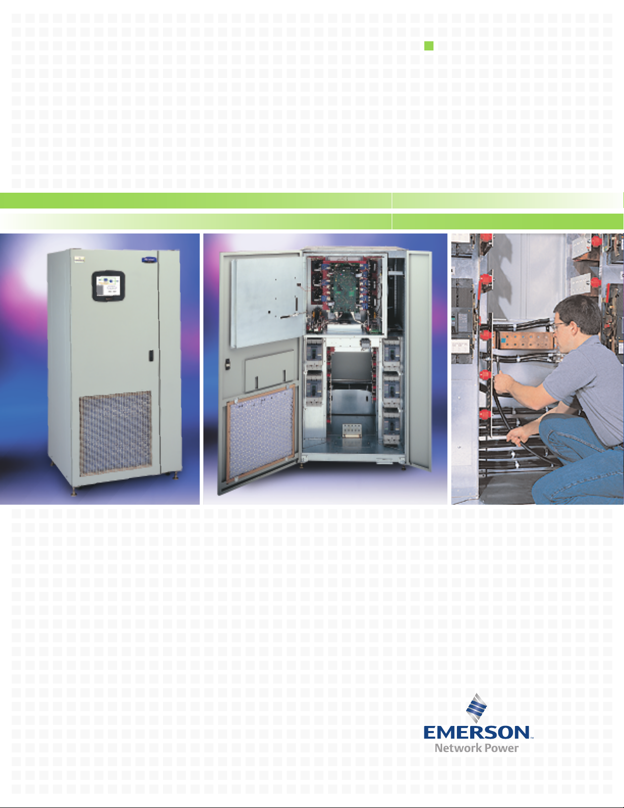
Liebert®STS2 Static Transfer Switch2
The Cornerstone of High-Availability Power Systems
Page 2
The Power to Protect Your Critical Operations
For maximum availability applications, the Liebert Static
Transfer Switch2 (STS2) provides an automatic, seamless
transfer between your critical load and the outputs of two
independent UPS systems in a dual-bus power configuration.
If the primary UPS should fail, the switch will automatically
transfer the loads to the alternate UPS.
Liebert is the market leader in dual-bus power systems,
building the world’s most reliable UPS and Static Transfer
Switch products. Liebert STS2 further extends our
market leadership with design benefits unmatched by
competitive products.
Standard Features Of The
Liebert STS2 Provide Greater
Overall Protection
Reliability:
100% rated, fuseless design.
Hot-swappable circuit breakers.
sh memory enables firmware updates while
a
Fl
supporting critical load.
Rack-out control/power assembly on units up to
600A to allow maintenance, service or full
acement without disrupting the critical load.
l
p
e
r
Flexibility:
ernal CANBUS protocol: high-bandwidth
t
In
communication between system components via
ed-pair cables. Options can be added as
t
wis
t
simple network nodes.
Dual-lug installation bus with pem nuts for
single-hand installation and “hot” torque service.
Low Total Cost Of Ownership:
Conservative design margins and excellent
overload capacity.
UL listed.
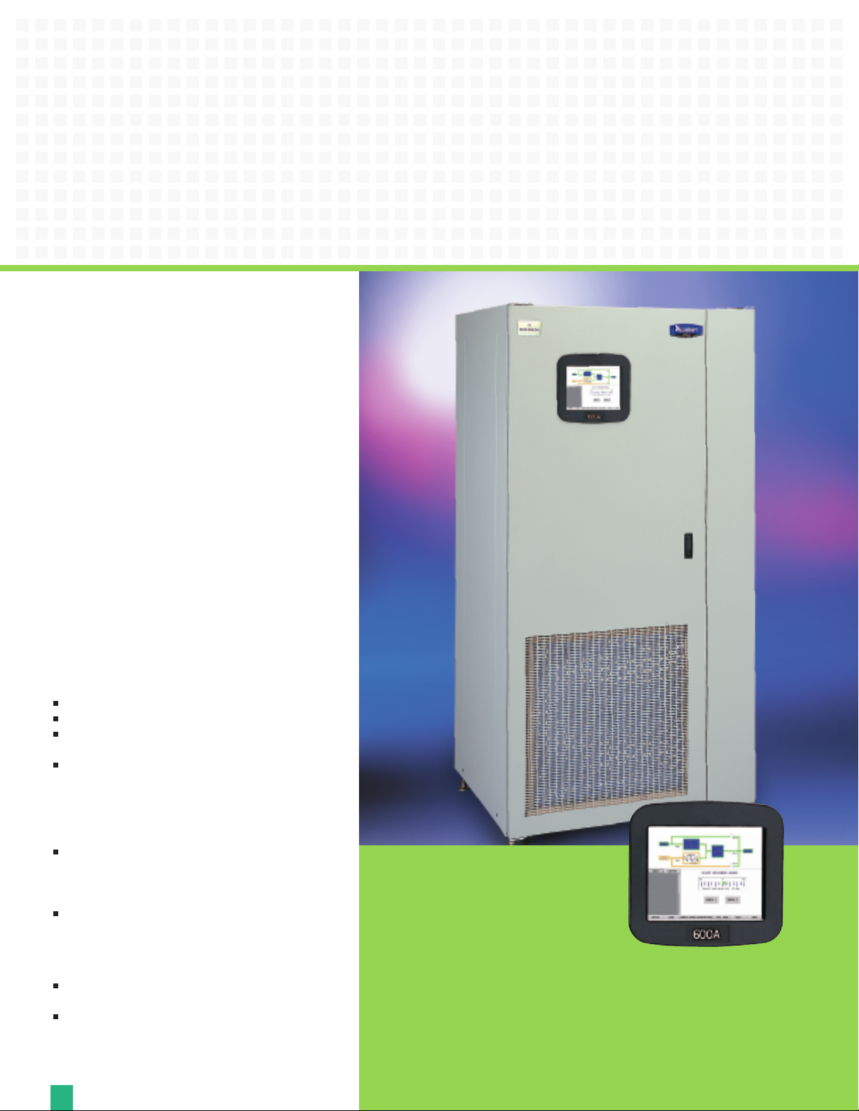
Color Touch-Screen Interface
The color touch-screen LCD interface allows
uickly check the status of the unit and
o q
u t
o
y
identify problems. The controls of the Liebert
STS2 are intuitive and simple.
vided into three segments. In addition to a system
i
or is d
onit
CD m
olor L
The c
mimic diagram, there is a Status/Alarm panel and a section dedicated to
perator instructions and menus. The screen allows you to configure the unit,
o
ontrol of the preferred source, auto/manual retransfer selection,
g the c
in
d
lu
inc
alarm notification and other system setpoints. You benefit from improved
perator effectiveness, reduced training time, and less chance of operator error.
o
2
Page 3
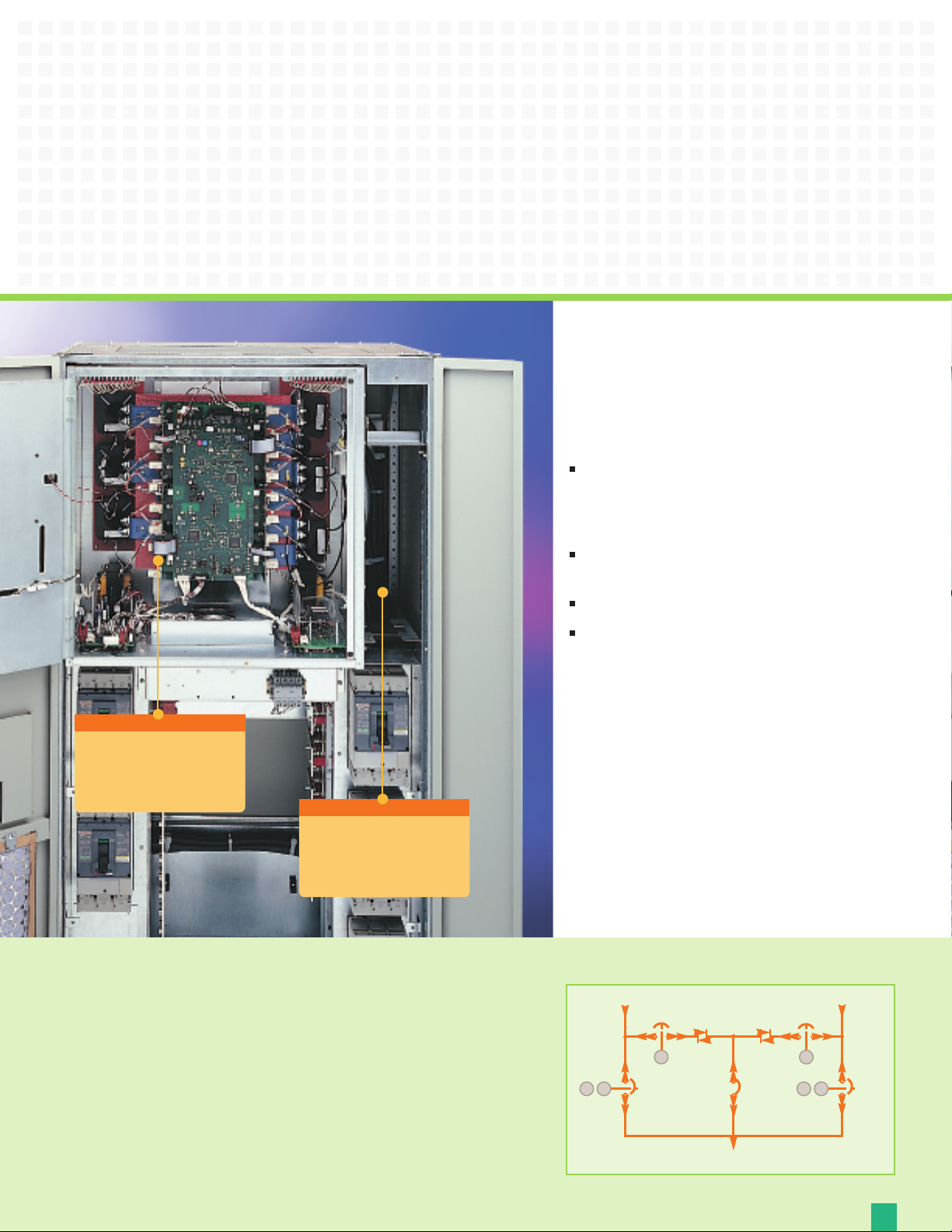
For units up to 600 amps,
the entire power and
ontrol module can be
c
removed as an assembly.
True Front-Access Design
All mechanical and electronic components of the Liebert
STS2 are accessible from the front of the unit for
installation and service—no side or rear access required.
This gives you several immediate benefits:
Greater freedom in system design. The Liebert STS2
can be placed adjacent to or in back of other
equipment. It can also be placed against a wall or
partition.
Simplified installation, with ample space for cable
connections through top and bottom access plates.
Less floor space required for maintenance access.
Designed for maintainability, with all key components
visible and accessible from the front of the unit,
without shutting down the connected load.
True Internal Redundancy
The Liebert STS2 has tripleredundant logic. Each DSP
controller is capable of working
independently, and each helps
monitor the other two. If one
malfunctions, the other two lock it
out. Each controller has power
feeds from both power supplies.
A separate compartment
for option modules
provides safe and
c
onvenient field access.
plies feature true
p
r su
e
w
o po
w
The t
dual-bus power distribution. Both
e dual inputs, one from each AC
v
a
h
e. All power connections
urc
o
t s
u
p
in
have diode protection, so that internal
ternal faults cannot propagate.
x
or e
, fault-resilient
ged
g
The r
sult is a r
e
u
package that is optimized for real-
ld applications.
or
w
One-Line Diagram
e 1
urc
So
CB1
K1
K2 K3 K1
CB4
CB3
System Output
CB2
K2
K3
Source 2
CB5
3
Page 4

Figures 1 and 2
show results for the
standard STS2 vs.
the optimized STS2
for the same
condition
(alternate source
lags 120 degrees)
respectively. The
optimized transfer
control algorithm
minimizes the
transformer
saturation current
resulting from an
out of phase
transfer.
Optimized Transfer Option Enhances
Cost-Efficient System Operation
Liebert offers a patented optimized transfer option for the Liebert STS2 that greatly
improves operation when used in primary side switching applications.
Figure 1 Standard STS2 transfer
load voltages
transformer fluxes
primary currents
ee also
S
e Paper “STS2
Whit
ptimized Transfer
O
une 4, 2004)
(J
.liebert.com.
www
4
” a
The Liebert STS2 can be used in two different types of high-availability dual bus
configurations—as primary or secondary side switches. For primary side switching,
imary or input of a downstream transformer. On
r
o the p
ed t
t
the unit is c
secondary side switching the Liebert STS2 is connected to the secondary or output of
two transformers.
One of the main advantages of using primary side switching is lower cost.
The
to 480V vs. 208V, and lower installation and wiring cost thanks to use of smaller three
wir
The one dr
saturation current each time switching occurs. The downstream transformer can
cause large peak saturation current during automatic transfers. The transformer
saturation is caused by DC-flux built-up during transfer, especially when the sources
are not in phase.
t
onnec
se savings are the result of only one power distribution unit, a lower current due
le.
b
e ca
figuration is the creation of transformer inrush
on
f this c
ck o
wba
a
Page 5
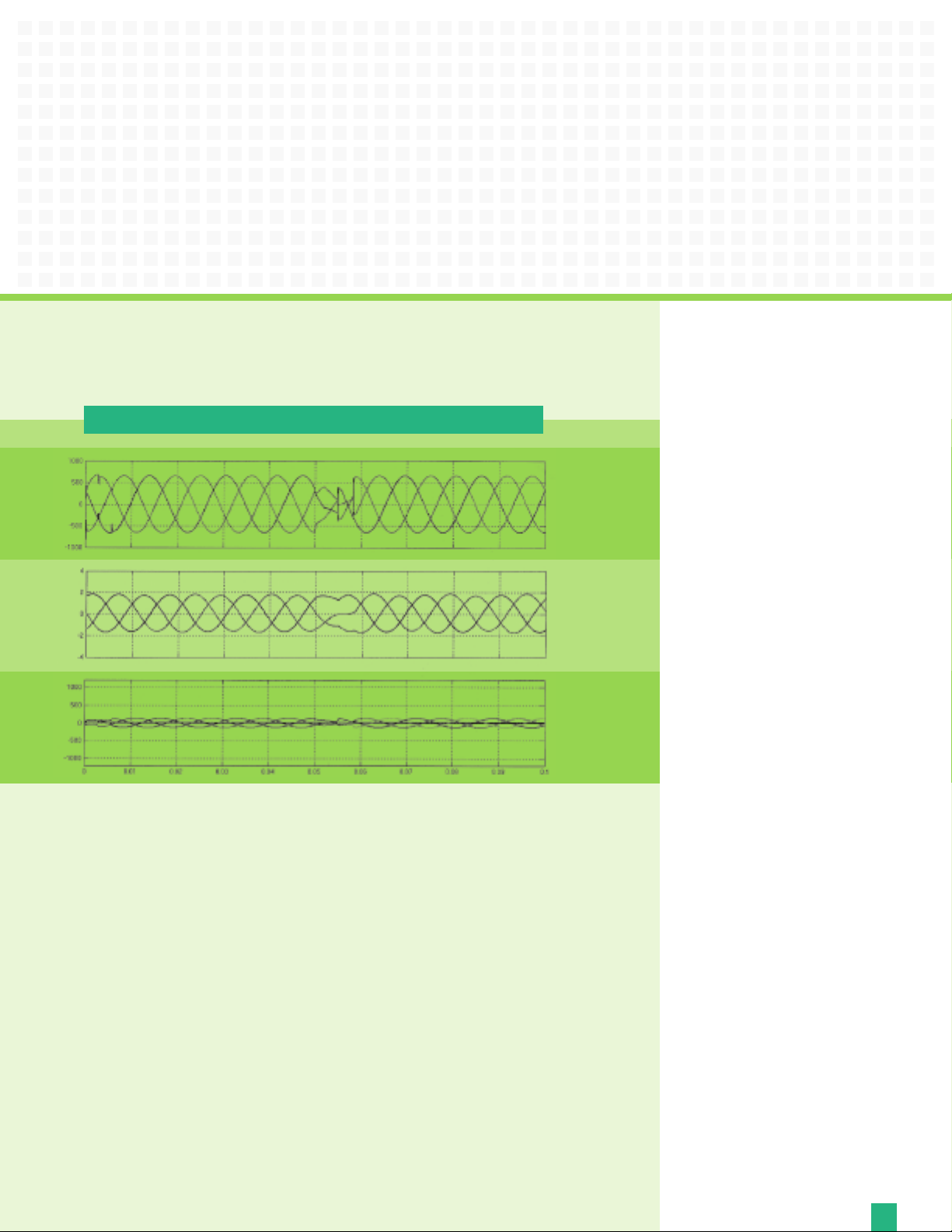
Figure 2 Optimized STS transfer
The patented Liebert static switch optimized transfer control algorithm
eliminates the downstream transformer inrush saturation.
The Liebert algorithm is designed to optimize transfer timing such that the volt-seconds applied to the
wnstream transformer primary is balanced, thus minimizing peak saturation current. This balance is
o
d
eved by directly computing the volt-second applied to the transformer during transfer events and
hi
c
a
determining the optimum time to turn on the alternate source SCRs in order to balance the volt-
fied tolerance.
i
d within s
on
ec
s
This results in a volt-second balancing algorithm that is independent of voltage wave shape,
voltage failure decay rate, etc., making it superior to other algorithms based on voltage
phase angle difference only.
pec
Liebert’s transfer control does
more than balance the flux.
Due to our unique approach to the
optimized transfer algorithm, transfer
time should not be the only performance
measure for this new optimized switch.
Liebert’s method, whenever possible,
also seeks to minimize voltage
disturbances while maintaining
transformer flux balance. It takes both
voltage disturbance and volt-second
balance into consideration.
Liebert has a unique flux balance
algorithm that doesn’t just “sit and
wait” for the balance point to occur.
Rather, we will “pulse fire” the SCRs
as soon as possible in order to
minimize the load discontinuity and
e the voltage disruption.
c
n
e
h
So how safe is this new
optimized Liebert STS2 for your
critical loads?
timized Liebert STS2 safely meets
p
The o
tandard (prior to 1996)
cal lo
e
x.
EMA s
ds. Li
a
le its al
hi
, w
s
r
ebert’s optimized
orithm control
g
th the CB
bo
and the latest ITIC standard (1996) for
iti
cr
STS2 eliminates the risk of transformer
saturation problems during automatic
ansf
tr
ensures minimum voltage disturbance
during transfers while still balancing
the flu
5
Page 6

Liebert STS2 Communication
and Product Options
Liebert STS2 has a wide choice of monitoring and
communications options to keep you connected to your
critical power protection system.
S-232 Terminal Port
R
is primarily used as an alternate user interface to
configure, control, and diagnose the system.
Input Contact Isolator (ICI) Board — Customizable
input relays allow alarms from other devices to be
displayed on Liebert STS2 display. Provides an interface
for up to eight user inputs. External messages and alarms
can be routed to the unit, via the ICI.
Programmable Relay Board (PRB) — Programmable
output relays for custom customer alarms and
connections. Up to two PRBs can be installed in the
Liebert STS2 to route system events to external devices.
Comms Board — Includes a terminal block to provide a
DTE connection to an external modem. This board also
provides a direct connection to a Liebert SiteScan
system, via an RS-422. SiteLink-12 or SiteLink-4 is
required for SiteScan to communicate with the
Liebert STS2.
Liebert IntelliSlot™485 Web Card ADPT
ystems to be viewed from the network using a web browser.
ws s
Allo
rs SNMP, Telnet and web management.
e
v
li
e
D
urity using HTTPS message encryption.
ec
s s
de
vi
o
Pr
Supports 10 and 100 MBit Ethernet for legacy and modern networks.
Provides compatibility with
vent data loss and ensure data availability.
e
r
o p
t
t SiteScan WEB
ts
por
p
Su
trending for proactive analysis and maintenance to ensure facility uptime.
Interfaces to
quick corrective action.
t In
r
be
e
Li
TCP/IP-based Ethernet network to allow the device to communicate with
network management systems (NMS) via SNMP. Events can be
ansmitted to the NMS to provide remote status monitoring,
tr
plus fault and alarm detection. The card includes an RJ-45 port for
r
an Ethe
e the s
t
a
egr
t
in
System (BMS) or out-of-band monitoring, using Modbus.
r
be
e
i
L
Liebert Nform alarm notification software, to facilitate
telliSlot 485 Web Card ADPT provides connectivity to any
net connection, via Category 5 cable. The card can also
tem with an existing Building Management
s
y
Liebert MultiLink shutdown software,
prise monitoring software, to provide
r
e
t
n
e
tandard on all units, this port
— S
®
Web
Options and Accessories
Seismic Anchors
f seismic activity, anchors are available for securing the unit to
o
a concrete floor to meet seismic Zone 4 requirements.
Seismic Floor Stand — Designed to level the unit and provide
bottom cabling access without relying upon a raised floor for
support. Available in 18, 24, 30, 36 inch heights.
Distribution Cabinet (Up to 600A) — An output distribution
cabinet mounts on the side of the STS2. It is a full height
section with hinged doors to allow for easy access. The cabinet
contains one vertically mounted I-line panelboard for load
distribution. The panelboard is totally enclosed with an accent
cover that provides access without exposing other portions of
the unit. The panelboard provides space for 100A through 250A
three-pole branch circuit breakers. It also includes a separate
isolated neutral bus bar and safety-ground bus bar for the
neutral and safety-ground connections.
Redundant Output Breaker — An output plug-in, nonautomatic circuit breaker provides redundancy in the output
power path. The breaker is connected in parallel with the
output plug-in non-automatic circuit breaker.
Input Junction Boxes and Cable (Up to 600A) — The input
junction box option is available to simplify input connections to
the STS2. Two input junction boxes and the associated flexible
10-foot long input cables are provided with this option.
vailable with bottom cable entrance only, typically when the
A
unit is located on a raised floor.
te Source Selection
o
m
e
R
Se
lection board may be installed in your STS2. This option
allows you choose the preferred input source from a remote
location. Terminal connections enable you to remotely select a
ed source in the same process as the local source
r
r
e
f
e
r
p
ansfer selection.
tr
Key Lockout Switch — The key lockout switch activates a
software lockout of the touch-screen display to prevent manual
transfers and configuration changes. When locked out, the
touch-screen becomes a read only display. A key is needed to
rform manual transfers or change settings.
pe
— To ensure stability for the unit in the event
al Remote Source
on
ti
p
— An o
6
Page 7

Critical Space Support from Emerson Network Power Service
rvice Capability
e
al S
t
o
T
Emerson Network Power Service provides a Basic, Essential and
Preferred level of maintenance and service that allows you to
select the complement of critical power system services that
uirements. These programs include
eq
ur r
o
t fits y
s
be
guaranteed four-hour response time, emergency service and
preventive maintenance.
With more than 300 Liebert-employed Customer Engineers and
a network of over 900 factory authorized service personnel, our
bilities, geographical coverage and ability to
a
p
cal ca
hni
ec
t
respond are second to none. These factory-trained service
professionals have direct access to the most comprehensive
actory authorized parts network in the industry. We also
f
provide them with immediate online access to detailed
hematics and your equipment’s complete service record
c
s
from the time it was started up.
e Monitoring — Always There, Always Alert
t
o
m
e
R
The key to providing proper service for your critical power systems is being aware of
that equipment’s operating status at any given time. For customers who need to have
these vital protection systems continuously monitored, but don’t want to do it
s, Emerson Network Power Service offers Remote Monitoring Service. This
e
v
l
e
ms
the
seamless, rapid-response system is designed to maximize the capabilities of your
Liebert equipment by maximizing the effectiveness of its monitoring capabilities.
Continuous 24-hour remote monitoring of UPS/power conditioning equipment,
environmental products and other critical space support systems is available. No
re your facilities are located, we can provide continuous oversight of a
he
r w
e
tt
a
m
wide range of critical installations from our Customer Response Center.
When a problem is detected, the monitoring system immediately alerts the Customer
e Center where each alarm is evaluated and processed. The center offers
pons
s
e
R
instant phone assistance using a customer-defined response and call escalation plan.
ll coordinate all service vendors, track the response and solution time for
t wi
r
be
e
Li
service calls and provide comprehensive reports on alarms and corrective actions.
7
Page 8

Emerson Network Power.
The global leader in enabling Business-Critical Continuity
™
.
EmersonNetworkPower.com
AC Power
Connectivity
DC Power
Embedded Computing
Embedded Power
Monitoring
Outside Plant
Power Switching & Controls
Racks & Integrated Cabinets
Services
Precision Cooling
Surge Protection
Liebert Corporation
1050 Dearborn Drive
P.O. Box 29186
Columbus, Ohio 43229
800 877 9222 Phone (U.S. &
Canada Onl
y)
614 888 0246 Phone (Outside U.S.)
614 841 6022
FAX
Via
Leonardo Da Vinci 8
Zona Industriale Tognana
35028 Piove Di Sacco (PD)
Italy
39 049 9719 111 Phone
39 049 5841 257 FAX
Emerson Network Power Asia Pacific
7/F., Dah Sing Financial Centre
108 Gloucester Rd, Wanchai
Hong Kong
852 25722201 Phone
852 28029250 FAX
liebert.com
24 x 7 Tech Support
800 222 5877 Phone
614 841 6755 (outside U.S.)
Ensuring The High Availability Of
Mission-Critical Data And Applications.
Specifications
eat Uncrated Dimensions Uncrated Shipping Dimensions
H
p Output (WxDxH) Weight (WxDxH) Weight
Am
ating (KW) (inches) (mm) (lbs) (kg) (inches) (mm) (lbs) (kg)
R
100 0.8 30x32x77 762x813x1956 780 354 48x44x82 1016x1194x2082 880 399
1.37 30x32x77 762x813x1956 780 354 48x44x82 1016x1194x2082 880 399
250
400 2.04 38x32x77 965x813x1956 1200 544 48x44x82 1016x1194x2082 1300 590
600 3.08 38x32x77 965x813x1956 1200 544 48x44x82 1016x1194x2082 1300 590
800 4.03 84x32x77 2134x813x1956 2500 1134 92x53x82 2337x1346x2082 2600 1179
1000 5.09 84x32x77 2134x813x1956 2500 1134 92x53x82 2337x1346x2082 2600 1179
Note: 1Shipping dimensions and weight include the pallet and packing material. Actual weights will vary depending on installed options.
1
Shi
pping
1
Operating Specifications
Voltage: 208, 220, 240, 380, 400, 415, 480 or 600 VAC (field selectable), +/- 10%
Frequency: 50 or 60 Hz (field selectable), +/- 0.5 Hz
Overload Capability: 125% for 10 minutes,150% for 2 minutes
Operating Temperature: 0 to 40° C
le every precaution has been taken to ensure accuracy and
Whi
completeness in this literature, Liebert Corporation assumes no
responsibility, and disclaims all liability for damages resulting
rom use of this information or for any errors or omissions.
f
ation. All rights reserved throughout
por
or
t C
r
be
e
© 2006 Li
pecifications subject to change without notice.
. S
ld
or
the w
All names referred to are trademarks or registered trademarks
of their respective owners.
ebert and the Liebert logo are registered trademarks
® Li
of the Liebert Corporation.
SL-20600 (R03/08) Printed in USA
Emerson Network Power and the Emerson Network Power logo are trademarks and service marks of Emerson Electric Co. ©2006 Emerson Electric Co.
 Loading...