


SEMPELL SERIES STE 4 CONTROL DEVICE FOR SAFETY VALVES
Operating instructiOns
Before installation these instructions must be fully read and understood
Series
STE 4 Control device for safety valves with
pneumatic actuator.
1 DANGER AND WARNING INDICATIONS
The construction of the Sempell safety
valves and control devices corresponds to
the standard technology and the valid safety
regulations.
Nevertheless, improper use or improper
installation may cause risks for personnel
or can lead to restrictions in regard of the
operational safety. Therefore Sempell GmbH
recommends the operator of the valves to take
appropriate measures and make sure that
the present operating instruction is read and
understood by the assigned personnel.
Please observe the following points besides
the notes given in the text
• Danger of burning when in contact with safety
valves and connecting pipes while operating
at increased temperature.
• Disassembly of the safety valve only in case
of pressureless system and after cooling
down. Wait for official permission. Disconnect
electrical supply.
• Protection against risks caused by
evaporation also in case of pressureless
system; for information please contact the
responsible safety inspector.
• After assembly check all sealing points in
regard of tightness.
• Carry ear protection during adjustment,
ifnecessary.
• Danger of burning by discharge of small
amounts of possibly hot medium in case
of safety valves with open spring bonnet
(typeSO..., VSE 1, VSR 1, VSE 8).
• Danger of injury while discharging in case of
open discharge line.
• Extreme vibrations (chatter) can lead to an
inadmissible increase of operating pressure
with possibly destruction of the safety valve
or to destruction of the balanced bellows with
unintentional escape of medium.
Exclusion of liability
Sempell GmbH cannot be held liable in case
of improper maintenance and adjustment of
a Sempell valve, use of inadmissible spare
parts or utilities and in case of temporary or
permanent connection of equipment with the
safety valve which is not approved by us.
Application limits
It is only allowed to use the safety valves and the
control device according to the details of this
operating instruction and/or according to the
parameters and application data agreed in the
delivery contract (see nameplate).
The application of the valve has to take place
adequate to the medium tolerances of the used
materials.
Warnings for the operating and maintenance
personnel
Before commissioning and maintenance works
familiarise yourself with the legal accident
prevention regulations, the local safety
instructions and this operating instruction and
observe them.
Use safety valve, control device and their
individual parts and accessories only for the
purpose intended by us.
Work on the electrical systems or equipment
must only be carried out by an electrician
or instructed personnel under control and
supervision of an electrician according to the
electrotechnical regulations.
www.valves.emerson.com © 2017 Emerson. All rights reserved.
MA.330.02.0505.E
VCIOM-02238-EN 15/01

SEMPELL SERIES STE 4 CONTROL DEVICE FOR SAFETY VALVES
Operating instructiOns
2 DESCRIPTION OF COMPONENTS
For the following sections the connection
diagram section 9.2 is valid unless other
provided.
2.1 Description of the function
The type-tested control device STE 4 pilots
the on- and off-switch of the loading air or
lifting air of the spring-loaded safety valve with
pneumatic actuator.
Under power the 2/2 way solenoid valves
(Y1,Y2, Y3) are closed and the 3/2 way solenoid
valve (Y4) connects de-energized the pressure
space (H) of the pneumatic actuator for lifting
air with the atmosphere.
Via pressure regulator (R1), filter (F) and throttle
(D), the loading air is on the loading cavity (B) of
the pneumatic actuator. It causes an additional
closing force to the spindle of the spring-loaded
safety valve with pneumatic actuator.
The pressure gauge MB in the control unit
shows the loading pressure, the control lamps
(Y1, Y2, Y3, B) shine.
D2D1
A2A1 G2 D3 A3 G3G1
Opening
The pressure switches (D1, D2, D3) inserted
into the impulse unit are adjusted to the desired
set pressure. In case of exceeding set pressure,
the solenoid valves (Y1, Y2, Y3) installed into
the control unit become de-energized. These
solenoid valves (Y1, Y2, Y3) switch by means of
the contacts of the relay and are assigned to
the corresponding pressure switch
Additionally, each of the three solenoid valves
become simultaneous de-energized by means
of a relay contact released by each of the three
pressure switches (D1, D2, D3). The solenoid
valve (Y4) is energized.
The loading air is relieved through the solenoid
valves (Y1, Y2, Y3). The lifting air is built up by
the solenoid valve (Y4). The controlled safety
valve opens.
The relief of the loading air also occurs if only
one of the three solenoid valves (Y1, Y2, Y3)
opens.
If the lifting air is not switched on, the
controlled safety valve opens after the
reduction of the loading air like a spring-loaded
safety valve.
Closing
If the system pressure drops below the reseat
pressure of the pressure switches (D1, D2, D3),
the solenoid valves (Y1, Y2, Y3, Y4) switch back.
The supply of lifting air stops. The pressure
space (H) of the pneumatic actuator relieves to
atmosphere and the loading air in the loading
cavity (B) builds up again. The controlled safety
valve closes.
P1 E1 P2E2 P3E3
room. Incase of higher control air pressures
(lifting air) a second pressure regulator R2
will be used toreduce the loading air pressure
(accessory, see system circuit diagram with
pressure regulator R2).
2.2 Description of the construction
According to the specification, there are three
separated control lines in the control device
STE 4, that means three pulse generators
(pressure switches) and three control units
(solenoid valves) with each an independent
pressure sense connection.
For testing and/or repair purpose it is possible
to temporarily put one of the three control
lines out of operation by means of the valve
interlock(G).
The control device STE 4 consists of the
functional groups:
impulse unit A161, electric switch unit A162 and
pneumatic control unit A163.
The impulse unit is composed of the
connections for the pressure sense lines (E1,
E2, E3), the shut-off valves with interlock (A1,
A2, A3) and the pressure switches (D1, D2, D3).
The test connections (P1, P2, P3) are located
between the shut-off valves and the pressure
switches. The pressure switches contain two
micro switches so that opening and closing
pressure can be set independent from each
other (P-min, P-max).
Sliding pressure operation
Open the safety valve below the set pressure
by an electrical impulse from the control
ATTENTION!
The components of the impulse unit A161 are
under system pressure!
2

SEMPELL SERIES STE 4 CONTROL DEVICE FOR SAFETY VALVES
Operating instructiOns
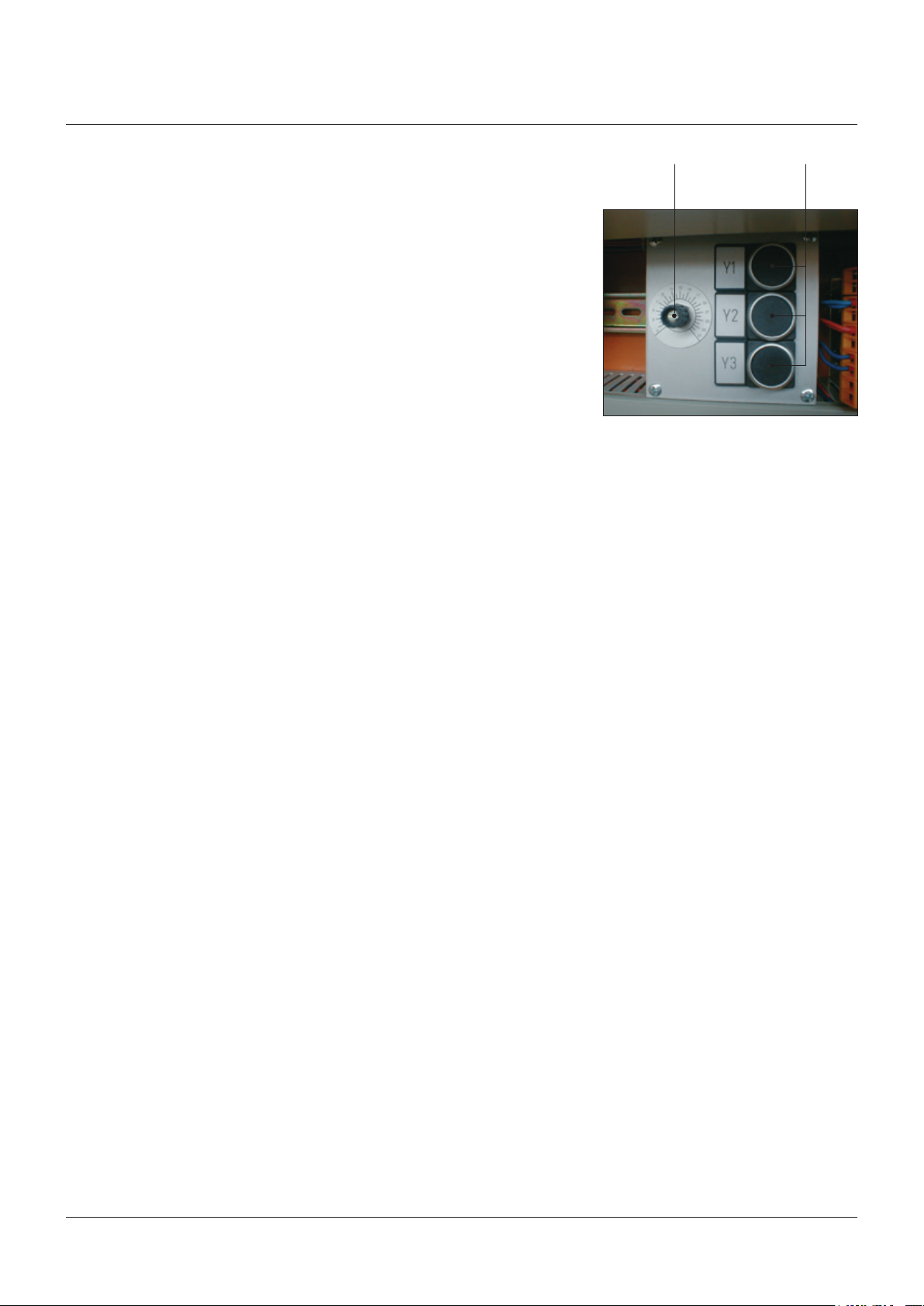
The electric switch unit includes the equipment
for signal treatment and control. At the bottom
side is the connection for the power supply.
Protected by an inspection window, control
lamps and manual switches for working and
testing are on the front panel. Pressing the
switch “Lamp Test” en ergizes all control
lamps.
The pneumatic control unit contains the
connections for the compressed-air supply
of the pneumatic section through pressure
regulator (R1) and air filter (F) to three closed-
circuit 2/2 way solenoid valves (Y1, Y2, Y3); one
open-circuit 3/2 way solenoid valve (Y4) and
the pressure gauges for loading and lifting air
(MB,MH).
At the upper side are the connections of the
control lines to the pneumatic actuator.
P4 MHY4
P5R1
Y1 Y2 Y3 F
3

SEMPELL SERIES STE 4 CONTROL DEVICE FOR SAFETY VALVES
Operating instructiOns
3 TECHNICAL DATA SAFETY VALVE CONTROL
Manufacturer Sempell GmbH
Name Control Device
Series STE 4
Compressed-air supply Max. 8 bar, 12 bar as option
Operating pressure for the pneumatic actuator Max. 8 bar
Max. 12 bar for lifting air
(accessory with pressure regulator R2)
Air consumption at opening About 26 Nm3 at 5 bar
Ambient temperature Max. 60 °C
Protection class IP 55
Weight About 78 kg
Type tested approval mark no. TÜV.SV ...-846
Electric connections:
Control device:
Input voltage 230 V, 50 Hz - 24 V DC or 48 V DC as option
Solenoid valve coils:
Connecting voltage 230 V, 50 Hz - 24 V DC or 48 V DC as option
4 OPERATING INSTRUCTIONS
Switch on the control device STE 4 by the key
operated switch at the electric switch unit.
The white control lamp “Operation” shows the
operating state. The pointer of the measuring
instrument in the “Test” field is in the black
area “Operation”.
ATTENTION!
A change of the lead sealed pressure switch
adjustment must take place inthe presence of
the independent TÜVinspector (TRD 601, sheet 2,
section4.2.1).
4.1 Adjustment after installation
Before delivery the pressure switches are
pre-set to the desired set pressure and closing
pressure (see section 2.1). After the installation
of the system a resetting of the pressure
switches (D1, D2, D3) may be necessary
under operating conditions (e.g. because of
temperature changes or after maintenance
works).
Therefore connect a spindle pump with
calibrated pressure gauge (accessory) at one
of the test connections (P1, P2, P3). Apply the
desired set pressure to the pressure switch.
Because of the closed pertaining shut-off
valve (A1, A2, A3) the system pressure has no
influence. In doing so, temporarily prevent the
response of the safety valve by the pneumatic
actuator.
Procedures
• Open the front door of the electric switch
unit. Set test switch in the “Test” field into
position“Test 1”.
Indicator: yellow control lamp in the “Test”
field blinks.
The lifting air to the pneumatic actuator is
temporarily switched off. The safety valve
remains fully operational.
Unlock and close the corresponding shut-off
valve (A1, A2 or A3) by means of interlock key.
Connect spindle pump with pressure gauge
at the test connection (P1 or P2 or P3) of the
previously closed shut-off valve (connections
see section 4.7.1).
4.2 Pre-setting
In case of a new adjustment or of great
deviations pre-set both micro switches of the
pressure switch (D1, D2, D3) approximately at
their set value first.
The precision pressure switches
Manocomb-Sem-2K have calibrated
nominal value scales for P-max and P-min
with an accuracy of ≤ 1%. By means of the
corresponding knurled-head screws pre-set
the switch points quite precise.
4.3 Set pressure control
Increase pressure with the spindle pump
connected to the test connection until the
control lamp P-max (red) flashes up. This is the
switch point. Register pressure reading on the
test gauge.
To change the switch point, turn the higher
knurled-head screw. Turn the adjusting screw
only a little when you are close to the switch
point. Lower excess pressure up to about 0bar
and then increase again until the pressure
switch actuates. Register pressure indicator
of the gauge again and correct switch point if
necessary.
Repeat procedures until the desired switch
pressure is reached.
In case of pressure decrease, the switching
band of the pressure switch with micro
switches can be determined. This is the
pressure difference between switch-on point
(flash up of the control lamp P-max) and
switch-back point (darken of the control lamp
P-max).
4

SEMPELL SERIES STE 4 CONTROL DEVICE FOR SAFETY VALVES
Operating instructiOns
4.4 Reseat pressure
Increase pressure with the spindle pump
connected at the test connection beyond the
desired closing pressure until the control
lamp P-min (yellow) shines. Slowly decrease
pressure until the control lamp P-min (yellow)
goes out. This is the switch point. Register
pressure reading of the gauge.
To change the switch point, turn the
corresponding adjusting screw. Turn adjusting
screw a little when approaching the switch
point. Lower excess pressure up to about 0 bar
and then increase again beyond the closing
pressure (control lamp P-min (yellow) shines).
Slowly decrease pressure until the pressure
switch actuates. Register pressure reading
of the gauge again and correct switch point if
necessary.
Repeat procedures until the desired switch
point is reached.
In case of pressure decrease the switching
band of the pressure switch with micro switch
can be determined. This is the pressure
difference between switch-on point (lighting
up of the control lamp P-min) and back switch
point (darken of the control lamp P-min).
After adjustment open the corresponding
shut-off valve again and lock it by means of the
interlock key. Put the cover on the pressure
switch and lead seal. Close front door again.
Switch back test switch of the electric switch
unit in the “Test” field.
Indicator: yellow control lamp in the field “Test”
does not signal.
4.5 Monitoring
Check daily the actual status of the control
device by visual check.
The actual function will be shown as follows:
• The safety valve is closed and loading air is
applied:
Electric switch unit:
white control lamp “Operation” shines. Gauge
reading is in the black area “Operation”.
Green lamps Y1, Y2, Y3 and B shine.
Pneumatic control unit:
gauge reading present at “Load” (MB).
Inspection window “Load” is green.
• The safety valve is opened and lifting air is
applied:
Electric switch unit:
white control lamp “Operation” shines. Gauge
reading is in the black area “Lifting”. Yellow
lamps Y4 and H shine. Red and yellow lamps
(P-min/P-max) 1 and/or 2 and/or 3 shine.
Pneumatic control unit:
gauge reading present at “Lifting” (MH).
Inspection window “Lifting” is green.
4.7 Testing
4.7.1 Check of pressure switch and operation of
the solenoid valves
For testing, one of the three pressure
switches (D1, D2, D3) can be separated from
the system by closing the unlocked shut-off
valve (A1,A2,A3) in the pressure sense line
(E1,E2,E3) by means of the valve interlock (G).
With a spindle pump with test gauge
(accessory) the desired set pressure can be
applied through the respective connection
(P1, P2, P3). Therefore connect the spindle
pump with a pressure hose and vice coupling
(Minimess Fa. Hydrotechnik) after removing the
knurled protective cap.
The control lamps P-min or P-max show the
gain of set and closing pressure (also see
sections4.3, 3.4).
If the safety valve shall not open during the
tests, set the test switch at field “Test” of the
control device in position “Test 1” to prevent the
opening of the 3/2 way solenoid valve (Y4) and
so the charge of the lifting air. At the same time
this switch position leads to the opening of only
the solenoid valve (Y1, Y2, Y3) assigned to the
specific pressure switch.
Have the set and closing pressure adjustment
checked once a year by an inspector.
ATTENTION!
A change of the lead sealed pressure switch
adjustment must take place inthe presence of
the independent TÜVinspector (TRD 601, sheet 2,
section4.2.1).
4.6 TROUBLE SHOOTING
Malfunction Cause Remedies
Loading air is
prematurely dropped
Pressure switch adjustment changed Pressure switch adjustment see chapter 4
Control line “Load” leaky Eliminate leaking point in the control line
Tube fittings leaky Retighten tube fittings
Electric supply deactivated Check electric connections
5
SEMPELL SERIES STE 4 CONTROL DEVICE FOR SAFETY VALVES
Operating instructiOns
• Check of the control legs 1 to 3
- Adjustment of the control air pressure to
2bar
Check of the pressure gauge “Load”
- Test switch into position “Test 1”
Signal lamp (orange) lights up.
• Check of control leg 1 (pressure switch D1,
solenoid valve Y1)
- Unlock and close shut-off valve A1.
- Slowly apply pressure to test connection P1
up to the response of the pressure switch.
Read corresponding pressure P-max at the
test gauge. Solenoid valve Y1 powerless. Drop
of the loading air; indicator at the pressure
gauge “Load” < 0.2 bar; no lifting air. Indicator
pressure gauge “Lifting” 0 bar, ampere meter
in position “Test 1”.
- Slowly drop pressure until the pressure
switch switches back.
Read corresponding pressure P-min at the
test gauge. Solenoid valve Y1 is energized and
closes. Loading air will be charged. Indicator
pressure gauge “Load” 2 bar.
- Open and lock shut-off valve A1.
• Check of control leg 2 (pressure switch D2,
solenoid valve Y2)
- Unlock and close shut-off valve A2.
- Slowly apply pressure to test connection P2
up to the response of the pressure switch.
Read corresponding pressure P-max at the
test gauge. Solenoid valve Y2 powerless. Drop
of the loading air; indicator at the pressure
gauge “Load” < 0.2 bar; no lifting air. Indicator
pressure gauge “Lifting” 0 bar, ampere meter
in position “Test 1”.
- Slowly drop pressure until the pressure
switch switches back.
Read corresponding pressure P-min at the
test gauge. Solenoid valve Y2 is energized and
closes. Loading air will be charged. Indicator
pressure gauge “Load” 2 bar.
- Open and lock shut-off valve A2.
• Set back to working conditions
- Turn test switch into position “Operation”.
Set control air pressure at normal operating
pressure.
Signal lamp (orange) goes out. Control at the
pressure gauge “Load”.
4.7.2 Check of the displacement force reserve of
solenoid valves Y1, Y2 and Y3
The solenoid valves (Y1, Y2, Y3) consist of a
electric actuated pilot valve and a pneumatic
actuated control valve.
At the electric actuated pilot valve, pressing the
respective push-button in the electric switch
unit lowers the operating tension up to a value
where a faultless solenoid has to switch. A
pressure drop of the loading air at the pressure
gauge (MB) shows the switching. The lifting air
is not actuated.
As the extent of the loading air pressure
counteracts the switch safety of the solenoid
valve check with the highest possible control
pressure.
By means of the magnetic actuated pilot valve
the pilot pressure is released. In case of the
pneumatic actuated control valve the height of
the air pressure brings about the switch safety.
To prove the displacement force reserve on the
control valve check with the lowest possible
control pressure (operation test according to
section 4.7.1).
Control the displacement force reserve at the
solenoid valves by pressing the switches at
a highest possible air pressure. Afterwards
control according to section 4.7.1 at lowered air
pressure.
The loading air pressure has to drop
top<0.2bar for all tests.
Once a year an inspector has to test the
displacement force reserves with the same
pressures.
Potentiometer Switch
• Check of control leg 3 (pressure switch D3,
solenoid valve Y3)
- Unlock and close shut-off valve A3.
- Slowly apply pressure to test connection P3
up to the response of the pressure switch.
Read corresponding pressure P-max at the
test gauge. Solenoid valve Y3 powerless. Drop
of the loading air; indicator at the pressure
gauge “Load” < 0.2 bar; no lifting air. Indicator
pressure gauge “Lifting” 0 bar, ampere meter
in position “Test 1”.
- Slowly drop pressure until the pressure
switch switches back.
Read corresponding pressure P-min at the
test gauge. Solenoid valve Y3 is energized and
closes. Loading air will be charged. Indicator
pressure gauge “Load” 2 bar.
- Open and lock shut-off valve A3.
6

SEMPELL SERIES STE 4 CONTROL DEVICE FOR SAFETY VALVES
Operating instructiOns
• Test course
Ampere meter into position “Operation”, Test
switch in position “Operation”.
- Open the front door and the cover plate of the
electric switch unit.
• Check of the displacement force reserve of
solenoid valve Y1
- Adjust the control air pressure to about
5bar.
Control at the pressure gauge “Load”.
- Turn potentiometer clockwise to the highest
value.
- Press and hold push-button for displacement
force reserve of solenoid valve Y1.
- Slowly turn down the potentiometer anti
clockwise until the solenoid valve Y1 actuate
(power will be reduced).
Solenoid valve Y1 opens. The load will be
relieved. The loading air pressure has to drop
to < 0.2 bar: indicator pressure gauge “Load”,
ampere meter into position “Test 1”, register
the reading of the potentiometer adjustment.
- Loosen push-button.
Solenoid valve Y1 closes (nominal voltage
atY1). Load will be charged.
• Check of the displacement force reserve of
solenoid valve Y2
Check of the control air pressure. Indicator at
the pressure gauge “Load”.
- Turn potentiometer clockwise to the highest
value.
- Press and hold push-button for displacement
force reserve of solenoid valve Y2.
- Slowly turn the potentiometer anti-clockwise
until the solenoid valve Y2 actuate (power will
be reduced).
Solenoid valve Y2 opens. The load will be
relieved. The loading air pressure has to drop
to < 0.2 bar: indicator pressure gauge “Load”,
ampere meter in position “Test 1”, register
the reading of the potentiometer adjustment.
- Loosen push-button.
Solenoid valve Y2 closes (nominal tension
atY2). Load will be charged.
Solenoid valve Y3 closes (nominal voltage
atY3). Load will be charged.
• Adjustment of the working state
- Adjust control air pressure on normal
working pressure.
Control at the gauge “Load”.
4.7.3 Lifting air charge
By putting the test switch into position “Test 2”
the 3/2 way solenoid valve (Y4) is energized and
so builds up the lifting air in the pressure space
(H) of the pneumatic actuator.
Indicator: yellow control lamp in the field “Test”
signals, control lamps Y4 and H shine, pressure
indicator gaugeMH, pointer in the gauge is in
the black field “Test 2”.
As the loading air simultaneously is applied
in the pressure space (B) of the pneumatic
actuator, the safety valve does not open. For
the special design with pressure regulator R2
adjust the control pressure at the pressure
regulator R1 to pressure level of pressure
regulatorR2.
4.7.4 Safety valve operation (pneumatic)
With the help of the lifting air the safety valve
can be opened fully to test the movability. In
doing so, for a short time the loading air will be
reduced and the lifting air will be built up.
It is possible to execute this test out of the
control room by remote operation and/or
locally at the control device by the push-button
“Hand Actuation”. At least one possibility has
to be there according to specification TRD 421
and AD-A2.
If a pressure lock valve is in the pneumatic
control unit to raise the lifting air (e.g. at drum
safety valves) it has to be actuated additionally.
Check the movability of the safety valve by an
inspector once a year.
• Check of the displacement force reserve of
solenoid valve Y3
Control of the control air pressure. Indicator
pressure gauge “Load”.
- Turn potentiometer clockwise to the highest
value.
- Press and hold push-button for displacement
force reserve of solenoid valve Y3.
- Slowly turn the potentiometer anti-clockwise
until the solenoid valve Y3 actuate (power will
be reduced).
Solenoid valve Y3 opens. The load will be
relieved. The loading air pressure has to drop
to < 0.2 bar: indicator pressure gauge “Load”,
ampere meter into position “Test 1”, register
the reading of the potentiometer adjustment.
- Loosen push-button.
7

SEMPELL SERIES STE 4 CONTROL DEVICE FOR SAFETY VALVES
Operating instructiOns
4.7.5 Safety valve adjustment (system pressure)
In case of checking the spring setting of the
safety valve only by the system pressure, block
the air supply to the control device STE 4 for a
short time.
Procedures
• Open front door of the electric switch unit.
Disconnect power supply by means of a key
operated switch.
• Indicator: white control lamp “Operation” is
out.
• Open front door of the pneumatic control unit.
Register the pressure shown at the gauge of
the pressure regulator R1. Shutoff air supply
at pressure regulator R1 by moving up and
turning left the handle of the regulator.
• Indicator: pressure shown at the pressure
gauge lowers to p = 0 bar.
The safety valve adjustment can now be
checked by increasing the system pressure
without influence of the pneumatic actuator.
After finishing the test, restore the control
pressure and the power supply.
Procedures
• Adjust control pressure at the pressure
regulator R1 to the previously registered
value again by moving up and turning right
the regulator handle. Read the pressure at
the gauge. Moving down the regulator handle
secures the adjustment.
• Close front door of the pneumatic control
unit.
• Switch on the power supply by means of the
key operated switch. Close front door of the
electric switch unit.
• Indicator: white control lamp “Operation”
shines.
4.7.6 Safety valve adjustment (pneumatic)
To execute the adjustment of the safety valve at
any system pressure and without considerable
disturbance of the actual working procedures,
the following test method is proposed:
For each safety valve determine once the
angle of inclination (perhaps already at the
inspection) (see diagram) by measuring at two
different system pressures. Slowly add the
lifting air to the respective system pressure by
means of pressure regulator valve R1. Record
the measuring points (lifting air pressure,
system pressure) in the diagram while the
opening of the safety valve starts.
For the following tests only one observation is
done at a random system pressure.
If the measured point is not at the straight line
correct the spring compression of the safety
valve.
Remark: the gradient of the measured
characteristic curve (straight line) is due to the
construction (relation between the effective
pneumatic piston surface and the effective
seat surface). After a modification of the spring
compression the characteristic curve has been
shifted parallel.
For recorded measurement the following
equipment is necessary:
• 2 pieces electric pressure transmitters
• 1 piece electric travel pickup
• 1 piece 4-channel test amplifier
• 1 piece 4-channel recorder
(This equipment can be obtained by
SempellGmbH)
Procedures
• Open the front door of the pneumatic control
unit. Register the shown pressure at the
gauge of the pressure regulator R1. Stop
the compressed-air supply at the pressure
regulator R1 by moving up and turning the
regulator handle anti-clockwise.
• Press and hold the hand actuation until the
solenoid valves Y1-Y4 have relieved the piston
space B.
• Indicator: shown pressure at the gauge
lowers to p = 0 bar.
ATTENTION!
Disconnect compressed-air supply at the control
device STE 4 so that the cavities of the pneumatic
actuator are not under pressure!
Measure and register system pressure, lifting
air pressure (P5) and lift of the safety valve.
The intersection of the straight line with
the abscissa (lifting air pressure = 0 barg)
corresponds with the set pressure of the safety
valve without lifting air.
8

SEMPELL SERIES STE 4 CONTROL DEVICE FOR SAFETY VALVES
Operating instructiOns
The pneumatic actuator is temporarily switched
off; the safety valve remains fully operational.
• In case of a cup spring safety valve
(type VSE8, SOT) unscrew the cap of the
pneumatic actuator and attach test cap with
displacement pickup to the safety valve.
• For a safety valve (VSE/VSR 1/5, SO, SB) with
mounted pneumatic actuator A160 assemble
the displacement pickup sideways to the
coupling.
• Connect pressure transmitter to lifting air (P5
in the pneumatic control unit). Also connect a
pressure transmitter to the system pressure.
• Press and hold fast hand actuation. Slowly
turn up handwheel of the pressure regulator
R1 (clockwise rotation). The pressure gauge
“Lifting” indicates the increasing lifting air
pressure. Increase pressure until the safety
valve opens. Measure and register pressure
and lift with the help of the measuring
devices.
• After finishing the opening loosen hand
actuation. The lifting air will be reduced and
the loading air will be built up again.
• The safety valve closes.
• At a pneumatic control unit equipped with an
additional pressure block valve for the lifting
air (e.g. for drum valves), it shall be actuated
additional to the switch “Hand Lifting”.
After finishing the test restore the original
control pressure again.
Procedures
• Re-adjust control pressure at the pressure
regulator R1 to the previously registered
value by moving up and turning clockwise the
regulator handle. Read the pressure at the
pressure gauge. Moving down the regulator
handle secures the adjustment.
Notice! In case of two or several safety valves
controlled by one control unit, all safety valves
open at the procedure described above. If only
the tested safety valve shall open, it is possible
to block the second safety valve mechanically
under consideration of special precautions.
After finishing the test, remove this safety valve
blocking in any case!!!
It is also possible to remove and shut the
control air hoses at the second safety valve.
5 TASKS OF THE INDEPENDENT INSPECTOR
These tasks are executed according to VdTÜV
Merkblatt SV ..-846.
2. Check reliability of the main valve in
connection with the control device.
3. Check correspondence of functional
diagram with the design.
4. Check each control leg according to
section4.7.1-3.
In doing so, especially check the adjustment
of the pressure switch, the displacement
force reserve and the reduction of the
air. The time to reduce air shall be about
the same for each control leg. Therefore
register the pressure in- and decrease of
lifting and loading air against time. The dead
time of the control device must correspond
to the pressure change rate of the protected
system.
During operation of the system
1. Shut off air. Check the adjustment of the
main valve without loading and lifting air.
Register lift of the main valve and the
system pressure against time. When the
main valve only opens to some extent due
to operation, check by extrapolation of the
lift course if the required lift is reached at
least at 10% above the admissible design
pressure. If the safety valve has capacity
reserves, the maximum possible lift for
discharging the required discharge amounts
must not be reached. This test is not
necessary for type-tested safety valves.
2. Fully open the main valve with the lifting air.
Check movability. This can also be executed
by hand through the manual switch at
operational pressure. Register system
pressure, air lifting pressure and lift of the
main valve against time.
3. The admissible ambient temperature of
60°C must not be exceeded at the position
of the electric components of the control
device.
5.2 At periodic inspections
1. Check external state.
2. Yearly check control device according to
section 5.1, point 4.
3. Yearly check the adjustment of the main
valve without loading and lifting air
(seesection4.7.6).
4. Yearly check operation of the main valve.
To evaluate the lifting course against time
execute the test with system pressure and
capacity comparable to the first test.
5. Check sliding faces at spindle, pistons,
guides and so on in contact with medium in
regard of defects. Examine welding seams
and greater wall interface thickness in
regard of cracks.
5.1 At inspection test
Before commissioning
1. Check correspondence of approved type test
identification number with the mark on the
control unit.
9

SEMPELL SERIES STE 4 CONTROL DEVICE FOR SAFETY VALVES
Operating instructiOns
6 PREVENTIVE MAINTENANCE
Observe safety instruction in section 1.
Before each operation ensure that
- the planned measures will not cause any faults
of the system or injury to persons
- control device and system part are properly
disconnected. Check that all circuits are
disconnected
At the control device
- disconnect all poles, prevent accidental
reconnection
- confirm that the equipment is not live, is
earthed and short-circuited
- fit barriers or covers to neighbouring live
components
6.1 Control and maintenance
Generally the pressure switches (D1, D2, D3)
in the impulse unit of the control are rarely
actuated. Check their functional readiness
once a year. Except the yearly control
(see section4.7.1 to 4.7.6) and occasional
readjustments (see section 4.1) there is no
further maintenance necessary.
The pressure regulator R1 in the control unit of
the compressed-air supply is a simple acting
membrane regulator with automatic release of
the secondary pressure.
By moving up and turning of the regulator
handle adjust the pressure and read it at the
pressure gauge. Moving down the regulator
handle secures the adjustment.
7 REPAIR INSTRUCTION AND INSTALLATION
Observe safety instruction in section 1.
Before each operation ensure that
- the planned measures will not cause any faults
of the system or injury to persons
- control device and system part are properly
disconnected
At the control device
- disconnect all poles, prevent accidental
reconnection
- confirm that the equipment is not live, is
earthed and short-circuited
- fit barriers or covers to neighbouring live
components
7.1 Storage
At delivery of the control device all connection
inlets are closed with corresponding caps.
Connection hoses and a key are attached to the
outside.
In this state the control device can be stored
without difficulties in closed, dust-free and
dry rooms lying on the fixing frame (inspection
window to the upper side).
A weather-protected outdoors storage is not
admissible.
Technical data
Primary pressure max.: 18 bar g
Secondary pressure: 0 - 10 bar g
(0 - 12 bar g option)
Flow rate: 0 - 2500 l/min
Water separating: 95 %
The mechanical acting filter F in the
maintenance unit of the compressed-air supply
is provided with a sight glass.
At the bottom side is the manual water trap.
By turning the plastic nut by hand for
about1.5turns, drain the filter. Afterwards
tighten the nut.
The plastic nut of the water separator is at
the bottom side of the control unit behind the
compressed-air supply.
Control the filter at least yearly and if
necessary, clean and drain the filter
(seesection 7.8).
Technical data
Primary pressure max.: 18 bar g
Area of flow rate: 0 - 2500 l/min
Water separating: 95 %
Filter element: 25 µm
Tank volume: 45 ml (cm
3
)
10

SEMPELL SERIES STE 4 CONTROL DEVICE FOR SAFETY VALVES
Operating instructiOns
7.2 Assembly
The delivery of the control device STE 4 takes
place assembled on a frame tightened by eight
screws.
At delivery the key of the front doors is placed
at the connection for the compressed-air
supply of the control unit. Further keys are
behind the front door of the electric switch unit.
It is only allowed to operate the control device
STE 4 by an air pressure of max. 8 bar. For the
special design with pressure regulator R2 the
lifting air can be up to max. 12 bar.
The control device has to be easy accessible to
facilitate adjusting and inspection. Protect the
location of the installation against wet and dirt.
Do not mount control device too close to the
safety valve (distance at least 3 m). For remote
location consider the delay times (see VdTÜVregulation ...-846).
ATTENTION!
Take care that no vibrations of the structure are
transferred to the control device as they can
fraudulently alter the measured value (switch
point). If necessary, install vibration dampers, e.g.
rubber buffers.
7.3 Pressure sense line
To connect the pressure sense line the
control device has three pressure connections
(E1,E2,E3). The pertaining tube fittings
(attached to delivery) have a welding connection
DA Ø 21.3 x 4 out of 316SS (similar to 1.4401).
It is possible to weld adequate pipe profiles
on these connections. The tube fittings have
to be assembled according to the instructions
(seesection 9.3).
If desired special connections and materials
are deliverable (request).
The inner diameter of the pressure tapping line
must be at least 15 mm.
The pressure connection has to take place
above an flexable laid line. In case of fixed line
bracings between pressure sense line and
welding connection of the control device it
may cause switch inaccuracy of the pressure
switches.
Guarantee by suitable measures that no
vibration can be transferred to the control
device. Dampen vibrations or pressure peaks
out of the medium by switch on throttles.
Connection of the sense line in the system:
For preventing too great pressure deviations
observe following instructions:
• If possible, connect not directly at the safety
valve inlet
• Connection of the system part to be secured
on a point with as great volume as possible
and as little as possible pressure fluctuations.
In case of pressure sense lines coming from
different systems (e.g. drum, superheater), take
care of the correct connection at the impulse
unit (different pressure setting of pressure
switches).
Prevent undue heating up of the control device
in case of connecting the control device at
pressure tapping lines with hot medium. The
temperature at the impulse unit inlet may not
exceed 60°C.
For steam as medium, connect via syphons or
water locks before the control device. Therefore
lay pressure sense line so that condensate can
be formed. The pressure sense line close to the
control unit may not be insulated.
Protect lines and control device from freezing.
If the impulse unit A161 is provided with
a heating (accessory H1, H2), observe the
following points:
At danger of freezing assure that the control
unit is always energized.
ATTENTION!
Also when the control unit is switched off by
the main switch (lockable switch), the heating
remains energized.
The power supply of the heater can be
disconnected by an additional switch.
For outdoor installation additionally protect the
system from direct exposure of sunlight.
After commissioning check the pressure sense
lines up to the pressure switch on tightness.
Upstream each pressure switch (D1, D2,D3)
there is a corresponding shut-off valve
(A1,A2,A3) in the impulse unit of the control
device. With these it is possible to close one
pressure tapping line for adjustment works.
The shut-off valves are secured by the valve
interlock (G) in such a way that only one
pressure switch can be put out of operation.
The other pressure switches remain in service
(see connection diagram section 9.2).
The test connections (P1, P2, P3) allow the
connection of a spindle pump with pressure
gauge to adjust and control the switch points
(see section 4.7.1).
Pressure test in the system
The components in the impulse unit A161 are
connected to system pressure through the
pressure sense lines. The pressure switches
(D1, D2, D3) may be loaded with a test pressure
up to 1.5× the end of scale value.
11

SEMPELL SERIES STE 4 CONTROL DEVICE FOR SAFETY VALVES
Operating instructiOns
7.4 Compressed-air connection
To connect the compressed-air supply the
control unit has a compressed-air connection
(pipe OD Ø 22).
The connections of the lifting and loading air
lines are on top of the pneumatic control unit.
According to the design of the control unit there
are several connections available for lifting and
loading air.
The pertaining (enclosed with the delivery) air
hoses enable the stress free connection to the
pneumatic actuator of the controlled safety
valve.
The air hoses for control unit and pneumatic
actuator have the same tube fittings ferrule
with which a pipe OD Ø 22 x 2 mm can be
fastened.
NOTE
• Clean the lifting and loading air lines by blowing out
with compressed air before connecting.
• Take care that the control air lines are assigned
correctly:
- Loading air line at the upper connection of the
pneumatic actuator
- Lifting air line at the bottom connection of the
pneumatic actuator
• If safety valves are applied with lifting air through a
block valve in the pneumatic control unit take care
of the correct connection of the lifting air lines.
7.5 Power-supply line
To connect the power supply the electric
switch unit has cable glands at the bottom side
through which the cable is lead into the control
device.
Open the front door and the cover plate of the
electric switch unit to connect the cable at the
connecting strip. The connection of the cable
at the connecting strip takes place according
enclosed wiring diagram.
The pertaining electric diagrams are at the
inner side of the front door of the impulse unit.
The power-supply line of the electric switch
unit is 230 V, 50 Hz; the mains supply voltage
24V DC or 48 V DC as option.
To connect the line for remote operation from
the control room and the conduit of foreign
impulses, there is a further cable gland for
each one at the bottom side of the control
device.
ATTENTION!
Observe the valid electrical regulations in any
case.
Work on the electrical systems or equipment
must only be carried out by an electrician
or instructed personnel under control and
supervision of an electrician according to the
electrical regulations.
7.6 Change of pressure switches D1, D2, D3
Procedures
• Open the front door of the electric switch
unitA162. Disconnect the power supply by the
key operated switch.
Indicator: white control lamp “Operation”
goes out.
• Open front door of the pneumatic control
unitA163. Register the shown pressure at the
gauge of the pressure regulator R1. Shutoff
compressed-air supply at the handwheel of
the pressure regulator R1.
Indicator: shown pressure at the gauge
lowers to p = 0 bar.
The pneumatic actuator is temporarily switched
off; the safety valve remains fully operational.
ATTENTION!
While working prevent a response of the safety
valve through the pneumatic actuator in any case.
Disassembly
To change the pressure switches D1, D2,D3
under operating conditions, separate the
pressure switch from the system by shutoff the
respective shut-off valve (A1, A2, A3).
If the specification prescribes a double closing
of the pressure line, replace the pressure
switch at pressureless state of the system to
secure.
The pressure switches (D1, D2, D3) are in the
impulse unit.
• Open front door of the impulse unit.
• Unlock by interlock key and close by turning
clockwise the corresponding shut-off valve
(A1, A2 or A3).
• Loosen the pertaining electric cable of the
pressure switch at the connecting strip in
the electric switch unit (see documentation
electrical switch unit).
ATTENTION!
Check if the respective shut-off valve (A1, A2
orA3) is closed.
• Loosen pipe joint (21) below the pressure
switch by means of two 19 mm picklocks.
Remove pressure switch including cable.
ATTENTION!
The components in the impulse unit A161 are
under high pressure!
In case of improper maintenance works, danger
occurs of damage through spraying liquid and/or
discharge of poisonous/inflammable gases under
high pressure.
Installation
To install the pressure switch, observe the
assembly instruction of the producer of the
tube fitting (product Parker) (see section 9.3).
• Join electric cable at the connecting strip
(seedocumentation electric switch unit).
• Adjust pressure switch with spindle pump to
the required pressure (see section 4.1 - 4.4
and4.7.1)
• Open and lock the corresponding shut-off
valve (A1, A2, A3)
After finishing the works, restore control
pressure and power supply.
Procedures
• Set air control pressure by the handwheel of
the pressure regulator R1 to the previously
registered value. Close front door of the
control unit.
• Switch on power supply by the key operated
switch. Close front door of the electric switch
unit.
• Indicator: white control lamp “Operation”
shines.
12

SEMPELL SERIES STE 4 CONTROL DEVICE FOR SAFETY VALVES
Operating instructiOns
7.7 Replacing (or cleaning) of the filter F
During these works close the air supply of the
control unit.
Procedures
• Disconnect power supply by means of the
key operated switch. Shutoff pressure
regulatorR1 by turning the handwheel
anti-clockwise.
The lifting and loading air of the pneumatic
actuator is temporarily switched off; the safety
valve remains fully operational.
Disassembly
The maintenance unit including filter F is
installed into the pneumatic control unit A163.
• Loosen threaded pipe elbow at the
pressure regulator R1 from the inlet line
(SW32,SW36).
• Detach four allen bolts size 4 mm at the
pressure regulator R1 and remove the whole
maintenance unit (pressure regulator R1 and
filter F). In doing so, do not loosen gasket
ring.
• Loosen the 4 cross-slotted bolts at the
maintenance unit and at the same action
block the hexagonal nuts. Remove bottom
cover.
• After loosen the hexagonal screw size 10 mm
with plate it is possible to remove the filter.
7.8 Ordering of spare and reserve parts
For spare parts storage or spare parts ordering
see spare part list section. 9.1.
For an order following details are necessary:
• Job and position number of the manufacturer
(see section 3)
• Type (see section 3)
• Part-no., quantity, part name and so on (see
section 9.1)
7.9 Instructions for transport
The control device STE 4 will be delivered
mounted on a frame and with closed
connection inlets.
The transport of the control device shall be:
• lying on a pallet with the fixing frame
(inspection window at the top side) with a
vehicle or
• hanging in a crane fastened with hoisting
bands fixed to the frame at the outside
(inspection window at the top side).
Clean or replace filter if necessary (see also
section 6.1).
Installation
The installation takes place in reverse order.
Observe the flow direction arrows at the upper
and bottom part while assembling.
After assembly restore control pressure and
power supply.
Procedures
• Adjust control pressure at the pressure
regulator R1 to the previously registered
value by moving up and turning clockwise
the regulator handle. Read the pressure at
the gauge. Moving down the regulator handle
secures the adjustment.
• Close front door of the pneumatic control
unit.
• Restore power supply with key operated
switch. Close the front door of the electric
switch unit.
• Indicator: white control lamp “Operation”
shines.
13

SEMPELL SERIES STE 4 CONTROL DEVICE FOR SAFETY VALVES
Operating instructiOns
8 DECLARATION TO EC-DIRECTIVE
For valves with CE-approval mark applies the following declaration:
Declaration to EC-Directive:
Conformity Declaration
According to Pressure Equipment Directive 97 / 23 / EG
1
2
Manufacturer
Pressure Device
Sempell GmbH
Werner von Siemens Straße
41352 Korschenbroich
Control Devices STE 4
with CE-Marking
3
4
5
6
7
8
9
Conformity Valuation Procedure
Designated Agency
Applied documents
Designated Agency Supervising
Quality Assurance
Applied co-ordinated standards
Applied Standards and Specification
Other Applied EC-Directives
Module H1
TÜV-CERT-Certification agency for QM-Systems
of TÜV Rheinland Industrie Service GmbH
Am Grauen Stein, 51101 Köln
registration number 0035
Type test VdTÜV SV 846
TÜV-CERT-Certification agency for QM-Systeme
of TÜV Rheinland Industrie Service GmbH
Am Grauen Stein, 51101 Köln
Valid EN material standards
TRD 421, AD2000-Merkblatt A2, TRD 110,
VdTÜV-Merkblatt SV 100,
DIN EN ISO 4126-5
None
10
Authorized representative of the manufacturer in EC
11
Signature:
12
Date
13
Name J.Ott Dr. H.D.Perko
14
Function responsible for product authorized representative for PED
14

SEMPELL SERIES STE 4 CONTROL DEVICE FOR SAFETY VALVES
Operating instructiOns
9 TECHNICAL DOCUMENTS
9.1 Spare parts list
SPARE PART LIST IMPULSE UNIT A161
Part no. Number of units Name of part Order no. / Dim. Manufacturer Material
A1-A3 3 Shut-off valve Sempell Div.
D1-D3 3 Pressure switch Manocomb-Sem-2K A116 Pinter Div.
P1-P3 3 Vice coupling 2103-01-44.00 Hydrotechnik Div.
SPARE PART LIST ELECTRICAL SWITCH UNIT A162
(see documentation electric switch unit)
SPARE PART LIST PNEUMATIC SWITCH UNIT A163
Part no. Name of part Order no. / Dim. Manufacturer Material
Y1-Y3 2/2 way valve 404-B-G1/2 Bürkert Div.
Y4 3/2 way valve 340-C- Bürkert Div.
MH, MB Pressure gauge 1 827 231 035 Bosch Div.
F, R Maintenance unit 354 A 052 Cubeair Div.
9.2 Drawings
CONTROL UNIT
Air connection for
loading
Air exhaust
1586
Air connection for lifting
498498 498
Belastung
Loading charge
380
Control unit
A163
Anlüftung
Liftin gr elevage
85
ø22 x 2
Main supply air connection
Electrical unit
A162
Power supply
Connection to control room
Vacant connection
Pressure unit
A161
Bauteilkennzeichen:
TÜVSV ..-846
component test mark :
Kommission:
Baujahr:
work no .
manufact. yea r
"X"
150150
105
Sense line connection
"A"
415
17,5
Ø9
77,5
stainless steel 316
4
37,5°
View “X”
View “A”
130
40
11
Ø15
Ø9
Ø21,3
Sense line
15

SEMPELL SERIES STE 4 CONTROL DEVICE FOR SAFETY VALVES
Operating instructiOns
PNEUMATIC CONTROL UNIT A163
Design B2
Manual lifting
MB
P4
Y1 Y3
Y2
MH
P5
Y4
D
R1
10
0
F
IMPULSE UNIT A161
D1
G1
A1
P1
E1
D2
a
bar
0
b
a= .... bar
b= .... bar
a
bar
0
b
a= .... bar
b= .... bar
a
bar
0
b
a= .... bar
b= .... bar
D3
G3
A3
G2
P3
A2
P2
E3
E2
16

SEMPELL SERIES STE 4 CONTROL DEVICE FOR SAFETY VALVES
Operating instructiOns
IMPULSE UNIT A161
Y3
Y4
MB
P4
P5
MH
W
B
H
Air supply
A163
R1
FD
Pneumatic
control unit
Y1
Y2
t
Pressure
Travel
System pressure
Power
supply
A162
Electrical
switching unit
A161
Pulse generating
unit
SYSTEM CIRCUIT DIAGRAM
B
A160
H
Safety valve
System
E1 E2
A1 A2
GG
P1
D1 D2
P2
P
D1
A1
C
G
GG
E1
Loading air
Lifting air
E3
A3
GY4
P3
D3
P5
P
P
A3A2 P3P2P1
E2
Pneumatic control unit A163
MH
A
PR
D3D2
E3
NOTES
E1 - E3 Pressure sense line
MB
A1 - A3 Shut-off valve
D1 - D3 Pressure switch
C Key
P4
Y3
A
P
G Valve interlock
P1 - P5 Test connection
D Throttle
F Filter
B Cavity for loading
H Cavity for lifting
Y2
PA
Y1 - Y3 Solenoid valve (closed-circuit principle)
Y4 Solenoid valve (open-circuit principle)
MB Pressure gauge for loading
MH Pressure gauge for lifting (easing)
R1 Pressure control valve
Y1
A
P
D
A160 Pneumatic actuator
Pulse generating unit A161
FR1
Compressed-air supply
17

SEMPELL SERIES STE 4 CONTROL DEVICE FOR SAFETY VALVES
Operating instructiOns
SYSTEM CIRCUIT DIAGRAM
Design with pressure regulator R2 for increased lifting air pressure
Pneumatic control unit A163
MB
Loading air
B
A160
Safety valve
System
E1 E2
A1 A2
GG
P1
D1 D2
P2
Lifting air
H
E3
A3
GY4
P3
D3
MH
P5
A
PR
P4
AY3P
Y2
PA
S
D
Y1
PA
NOTES
E1 - E3 Pressure sense line
A1 - A3 Shut-off valve
D1 - D3 Pressure switch
C Key
G Valve interlock
P1 - P5 Test connection
D Throttle
F Filter
B Cavity for loading
H Cavitye for lifting
Y1 - Y3 Solenoid valve (closed-circuit principle)
Y4 Solenoid valve (open-circuit principle)
MB Pressure gauge for loading
MH Pressure gauge for lifting (easing)
R1, R2 Pressure control valve
A160 Pneumatic actuator
S Safety valve
Pulse generating unit A161
SYSTEM CIRCUIT DIAGRAM
Loading
Safety valve
"Z"
R2
Lifting
ø22 x 2 Pipe
Compressed air hose ø19 mm
Sense line
System
pressure
R1 F
Compressed-air
supply
Air exhaust
Compressed air supply connection pipe ø22 x 2
Main supply
Scope of supply
Pipe ø22 x 2 on site
Detail “Z”
18

SEMPELL SERIES STE 4 CONTROL DEVICE FOR SAFETY VALVES
Operating instructiOns
SYSTEM CIRCUIT DIAGRAM WITH TWO SAFETY VALVES
Lifting by manual operating (design B2)
Loading
Safety valve drum
Lifting
DIAGRAM FOR THE ADJUSTMENT CONTROL OF THE SAFETY VALVE
Sense line
Pressure
superheater
Pressure drum
Safety valve superheater
Water lock
Lifting air
pressure
(bar)
1
Characteristic line
2
Set pressure (uncontrolled`)
System pressure (bar`)
19

SEMPELL SERIES STE 4 CONTROL DEVICE FOR SAFETY VALVES
Operating instructiOns
9.3 Installation instructions A-Lok tube
fittings
A-Lok tube fittings are supplied completely
assembled.
General remarks
1. The end of the tube must be cut square;
any burrs may be removed without causing
undue chamfering of the tube end.
2. Insert the tube into the fitting. Ensure that
the tube is firmly butted home into the body
of the fitting. Finger tight the nut.
3. With the body firmly held, mark the nut in
the finger tightened position, and tighten the
nut 1¼ turns from the marked position. The
connection is then correctly completed.
3
4. For tube fittings up to
/
16“ and 4 mm OD,
only ¾ turn is necessary.
High pressure applications, high safety factor
systems
To allow for possible variations in tube
hardness when the application demands the
maximum pressure sealing capabilities of the
fitting, it is recommended that the nuts are
tightened until the tube cannot be rotated by
hand. From this point the nut should then be
tightened 1¼ turns.
Holding the body with a spanner, the nut is
tightened to the original position and then given
a slight extra effort to retain positive sealing.
Retightening and disassembly
With A-Lok tube fittings the connection can be
disconnected and re-tightened many times and
the same reliable, safe, leak-proof connection
obtained.
Simply insert the tube into the body and butt
home firmly.
Technical Information and Customer Service:
Sempell GmbH
Werner-von-Siemens-Straße
41352 Korschenbroich
Germany
Phone +49-2161-615-0
Fax +49-2161-64761
© 2017 Emerson. All rights reserved.
20
 Loading...