

Page 1
Installation Guide
U
Regen
200V, 400V, 575V, 690V
Part Number: 0471-0029-02
Issue: 2
www.controltechniques.com
Page 2

General Information
The manufacturer accepts no liability for any consequences resulting from inappropriate, negligent or incorrect
installation or adjustment of the optional operating parameters of the equipment or from mismatching the variable speed
drive with the motor.
The contents of this guide are believed to be correct at the time of printing. In the interests of a commitment to a policy
of continuous development and improvement, the manufacturer reserves the right to change the specification of the
product or its performance, or the contents of the guide, without notice.
All rights reserved. No parts of this guide may be reproduced or transmitted in any form or by any means, electrical or
mechanical including photocopying, recording or by an information storage or retrieval system, without permission in
writing from the publisher.
Drive software version
This product is supplied with the latest version of software. If this product is to be used in a new or existing system with
other drives, there may be some differences between their software and the software in this product. These differences
may cause this product to function differently. This may also apply to drives returned from a Control Techniques Service
Centre.
The software version of the drive can be checked by looking at Pr 11.29 (or Pr 0.50) and Pr 11.34. The software version
takes the form of zz.yy.xx, where Pr 11.29 displays zz.yy and Pr 11.34 displays xx, i.e. for software version 01.01.00,
Pr 11.29 would display 1.01 and Pr 11.34 would display 0.
If there is any doubt, contact a Control Techniques Drive Centre.
Environmental statement
Control Techniques is committed to minimising the environmental impacts of its manufacturing operations and of its
products throughout their life cycle. To this end, we operate an Environmental Management System (EMS) which is
certified to the International Standard ISO 14001. Further information on the EMS, our Environmental Policy and other
relevant information is available on request, or can be found at www.greendrives.com.
The electronic variable-speed drives manufactured by Control Techniques have the potential to save energy and
(through increased machine/process efficiency) reduce raw material consumption and scrap throughout their long
working lifetime. In typical applications, these positive environmental effects far outweigh the negative impacts of product
manufacture and end-of-life disposal.
Nevertheless, when the products eventually reach the end of their useful life, they can very easily be dismantled into their
major component parts for efficient recycling. Many parts snap together and can be separated without the use of tools,
while other parts are secured with conventional screws. Virtually all parts of the product are suitable for recycling.
Product packaging is of good quality and can be re-used. Large products are packed in wooden crates, while smaller
products come in strong cardboard cartons which themselves have a high recycled fibre content. If not re-used, these
containers can be recycled. Polythene, used on the protective film and bags for wrapping product, can be recycled in the
same way. Control Techniques' packaging strategy favours easily-recyclable materials of low environmental impact, and
regular reviews identify opportunities for improvement.
When preparing to recycle or dispose of any product or packaging, please observe local legislation and best practice.
Copyright © February 2007 Control Techniques Drives Limited
Issue Number: 2
Software: 01.07.01 onwards
Page 3
How to use this guide
System design
Programming
and
commissioning
This user guide provides complete information for installing and operating a Unidrive SP from start to finish.
The information is in logical order, taking the reader from receiving the drive through to fine tuning the performance.
NOTE
There are specific safety warnings throughout this guide, located in the relevant sections. In addition, Chapter 1 Safety
Information contains general safety information. It is essential that the warnings are observed and the information
considered when working with or designing a system using the drive.
This guide should be read in-line with the relevant User Guide also, which contains additional information which may be
required whilst designing and commissioning a regen system.
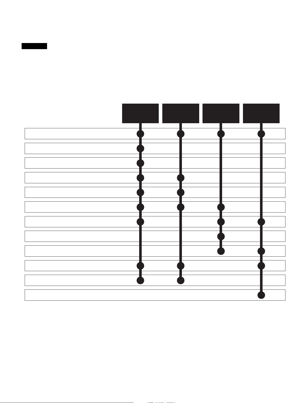
This map of the user guide helps to find the right sections for the task you wish to complete:
1 Safety information
2 Introduction
3 Product information
4 System design
5 Mechanical Installation
6 Electrical installation
7 Getting started
8 Optimisation
9 Parameters
Familiarisation System design
commissioning
Programming
and
Troubleshooting
10 Technical data
11 Component sizing calculations
12 Diagnostics
Page 4

Contents
1 Safety Information .................................6
1.1 Warnings, Cautions and Notes .............................6
1.2 Electrical safety - general warning ........................6
1.3 System design and safety of personnel ................6
1.4 Environmental limits ..............................................6
1.5 Compliance with regulations .................................6
1.6 Special note on SECURE DISABLE/ENABLE
function in regen operation ....................................6
1.7 Adjusting parameters ............................................6
2 Introduction ............................................7
2.1 Regen operation ....................................................7
2.2 Advantages of Unidrive SP operating in regen
mode .....................................................................7
2.3 Principles of operation ...........................................7
2.4 Power flow .............................................................8
2.5 Synchronisation .....................................................8
2.6 Current trimming ...................................................8
2.7 Regen system configurations ................................8
2.8 Regen drive system types .....................................9
3 Product Information ............................12
3.1 Model number .....................................................12
3.2 Nameplate description ........................................12
3.3 Ratings ................................................................13
3.4 Drive features ......................................................17
3.5 Unidrive SPMC half controlled thyristor rectifier ..19
3.6 Unidrive SPMC/U technical data .........................20
3.7 Output Sharing Chokes (for motoring drives
only) ....................................................................22
3.8 Options ................................................................23
3.9 Items supplied with the drive ...............................25
3.10 Regen components .............................................25
4 System design .....................................30
4.1 Introduction .........................................................30
4.2 Power connections ..............................................30
4.3 Non standard applications ...................................40
4.4 Cable length restrictions ......................................40
4.5 Cable types and lengths ......................................42
4.6 Exceeding maximum cable length ......................42
5 Mechanical Installation .......................45
5.1 Safety information ...............................................45
5.2 Planning the installation ......................................45
5.3 Regen component dimensions ............................46
5.4 External EMC filter .............................................55
5.5 Enclosure ............................................................62
5.6 Cubicle design and drive ambient temperature ...64
6 Electrical Installation .......................... 65
6.1 Power connections ............................................. 66
6.2 AC supplies ........................................................ 74
6.3 Cable and fuse ratings ....................................... 75
6.4 EMC (Electromagnetic compatibility) ................. 77
6.5 External EMC filter ............................................. 78
6.6 Control connections ........................................... 83
7 Getting started .................................... 86
7.1 Regen parameter settings .................................. 86
7.2 Regen drive sequencing .................................... 86
7.3 Regen drive commissioning ............................... 87
7.4 Motoring drive commissioning ............................ 88
8 Optimisation ........................................ 89
8.1 Power feed-forward compensation (Pr 3.10) ..... 89
8.2 Current loop gains .............................................. 89
8.3 Voltage controller gain (Pr 3.06) ........................ 90
8.4 Power factor correction (Pr 4.08) ....................... 91
8.5 Current trimming ................................................ 91
9 Parameters .......................................... 92
9.1 Parameter ranges and variable maximums: ...... 92
9.2 Menu 0: Basic parameters ................................. 93
9.3 Menu 3: Regen sequencer ................................. 94
9.4 Menu 4: Current control ................................... 100
9.5 Menu 5: Regen control ..................................... 107
9.6 Menu 6: Clock .................................................. 111
9.7 Menu 7: Analogue I/O ...................................... 119
9.8 Menu 8: Digital I/O ........................................... 132
9.9 Menu 9: Programmable logic, motorised pot
and binary sum ................................................. 138
9.10 Menu 10: Status and trips ................................ 146
9.11 Menu 11: General drive set-up ......................... 154
9.12 Menu 12: Threshold detectors and variable
selectors ........................................................... 165
9.13 Menu 14: User PID controller ........................... 172
9.14 Menus 15, 16 and 17: Solutions Module set-up 178
9.15 Menu 18: Application menu 1 ........................... 179
9.16 Menu 19: Application menu 2 ........................... 180
9.17 Menu 20: Application menu 3 ........................... 181
9.18 Menu 22: Additional menu 0 set-up ................. 182
10 Technical data ................................... 183
10.1 Drive ................................................................. 183
10.2 Supply requirements ........................................ 191
10.3 Protection ......................................................... 192
10.4 Component data ............................................... 196
10.5 Optional external EMC filters ........................... 199
11 Component sizing ............................. 203
11.1 Sizing of MCB for switching frequency filter ..... 203
11.2 Resistor sizing for multiple drive systems ........ 204
11.3 Thermal / magnetic overload protection for soft
start circuit ........................................................ 204
4 Unidrive SP Regen Installation Guide
www.controltechniques.com Issue Number: 2
Page 5

12 Diagnostics ........................................206
12.1 Trip indications ..................................................206
12.2 Alarm indications ...............................................215
12.3 Status indications ..............................................215
12.4 Displaying the trip history ..................................215
Unid rive SP Regen Insta llation G uide 5
Issue Number: 2 www.controltechniques.com
Page 6
Safety
Information
Introduction
Product
information
System
design
Mechanical
installation
Electrical
installation
1 Safety Information
1.1 Warnings, Cautions and Notes
A Warning contains information which is essential for
avoiding a safety hazard.
WARNING
A Caution contains information which is necessary for
avoiding a risk of damage to the product or other equipment.
CAUTION
NOTE
A Note contains information which helps to ensure correct operation of
the product.
1.2 Electrical safety - general warning
The voltages used in the drive can cause severe electrical shock and/or
burns, and could be lethal. Extreme care is necessary at all times when
working with or adjacent to the drive.
Specific warnings are given at the relevant places in this guide.
1.3 System design and safety of
The drive is intended as a component for professional incorporation into
complete equipment or a system. If installed incorrectly, the drive may
present a safety hazard.
The drive uses high voltages and currents, carries a high level of stored
electrical energy, and is used to control equipment which can cause
injury.
Close attention is required to the electrical installation and the system
design to avoid hazards either in normal operation or in the event of
equipment malfunction. System design, installation, commissioning and
maintenance must be carried out by personnel who have the necessary
training and experience. They must read this safety information and this
guide carefully.
The STOP and SECURE DISABLE functions of the drive do not isolate
dangerous voltages from the output of the drive or from any external
option unit. The supply must be disconnected by an approved electrical
isolation device before gaining access to the electrical connections.
None of the drive functions must be used to ensure safety of
personnel, i.e. they must not be used for safety-related functions.
Careful consideration must be given to the functions of the drive which
might result in a hazard, either through their intended behaviour or
through incorrect operation due to a fault. In any application where a
malfunction of the drive or its control system could lead to or allow
damage, loss or injury, a risk analysis must be carried out, and where
necessary, further measures taken to reduce the risk - for example, an
over-speed protection device in case of failure of the speed control, or a
fail-safe mechanical brake in case of loss of motor braking.
personnel
Getting
started
of fuses or other protection, and protective earth (ground) connections.
This guide contains instruction for achieving compliance with specific
EMC standards.
Within the European Union, all machinery in which this product is used
must comply with the following directives:
Optimisation Parameters
98/37/EC: Safety of machinery.
89/336/EEC: Electromagnetic Compatibility.
Technical
data
Component
sizing
Diagnostics
1.6 Special note on SECURE DISABLE/
ENABLE function in regen operation
In regen operation the enable input of the Regen drive stage has no
safety functions. It only enables the active rectifier operation. It does not
disable any operation of the motoring drive(s) and it does not prevent the
regen stage from producing DC power.
The enable input of the motoring drive stage can be used for safety
functions if required. Consult the Unidrive SP User Guide for information
on SECURE DISABLE.
1.7 Adjusting parameters
Some parameters have a profound effect on the operation of the drive.
They must not be altered without careful consideration of the impact on
the controlled system. Measures must be taken to prevent unwanted
changes due to error or tampering.
1.4 Environmental limits
Instructions in this guide regarding transport, storage, installation and
use of the drive must be complied with, including the specified
environmental limits. Drives must not be subjected to excessive physical
force.
1.5 Compliance with regulations
The installer is responsible for complying with all relevant regulations,
such as national wiring regulations, accident prevention regulations and
electromagnetic compatibility (EMC) regulations. Particular attention
must be given to the cross-sectional areas of conductors, the selection
6 Unidrive SP Regen Installation Guide
www.controltechniques.com Issue Number: 2
Page 7
Safety
Information
Introduction
Product
information
System
design
Mechanical
installation
Electrical
installation
2 Introduction
The following installation guide should be read in conjunction with the
Unidrive SP User Guide.
Any Unidrive SP drive can be configured as an AC Regenerative Unit
(hereafter referred to as a Regen drive).
This guide covers the following:
• Principles and advantages of operation in regen mode
• Safety information
• EMC information
• Detailed information on additional components required
• System design
• Special considerations
• Installation
• Commissioning and optimisation of the completed system
At least two Unidrive SP drives are required to form a complete
regenerative system - one connected to the supply and the second one
connected to the motor. A Unidrive SP in regen mode converts the AC
mains supply to a controlled DC voltage, which is then fed into another
drive(s) to control a motor(s).
NOTE
The motoring drive(s) in a regen configuration could be another drive
other than a Unidrive SP, e.g. Unidrive classic or Commander SK etc.
NOTE
The following regen components are also required in addition to the
Unidrive SP drives.
1. Regen inductor
2. Switching frequency filter inductor
3. Switching frequency filter capacitor
4. Softstart resistor
5. Varistors
6. MCBs
7. Overload relays
Getting
started
Optimisation Parameters
Technical
data
Component
sizing
Diagnostics
• Transient operation is possible between 40 and 72Hz down to the
above supply voltage levels for approximately 1 second.
• The Regen and motoring drives are identical (when using Unidrive
SP).
• Power feed-forward term available, using analogue I/O set-up
• A fast transient response is possible using the power feed forward
term.
2.3 Principles of operation
The input stage of a non-regenerative AC drive is usually an
uncontrolled diode rectifier, therefore power cannot be fed back onto the
AC mains supply. By replacing the diode input rectifier with a voltage
source PWM input converter (Unidrive SP), AC supply power flow can
be bi-directional with full control over the input current waveform and
power factor. Currents can now be controlled to give near unity power
factor and a low level of line frequency harmonics.
In the case of a Unidrive SP operating in regenerative mode, the IGBT
stage is used as a sinusoidal rectifier converting the AC supply to a
controlled DC voltage.
Furthermore, by maintaining the DC bus voltage above the peak supply
voltage the load motor can be operated at a higher speed without field
weakening. Alternatively, the higher output voltage available can be
exploited by using a motor with a rated voltage higher than the AC mains
supply, thus reducing the current for a given power.
Regen inductors must be used to ensure a minimum source impedance,
these being selected and specified later in the guide.
The difference between the PWM line voltage and the supply voltage
occurs across the regen inductors at the Regen drive. This voltage has a
high frequency component, which is blocked by the regen inductor, and
a sinusoidal component at line frequency. As a result currents flowing in
these inductors are sinusoidal with a small high frequency ripple
component.
2.1 Regen operation
For use as a regenerative front end for four quadrant operation.
Regen operation allows bi-directional power flow to and from the AC
supply. This provides far greater efficiency levels in applications which
would otherwise dissipate large amounts of energy in the form of heat in
a braking resistor.
The harmonic content of the input current is negligible due to the
sinusoidal nature of the waveform when compared to a conventional
bridge rectifier or thyristor front end.
2.2 Advantages of Unidrive SP operating in regen mode
The main advantages of an AC Regen system are:
• Energy saving
• The input current waveform is sinusoidal
• The input current has a near unity power factor
• Power factor correction can be implemented using Pr 4.08
• The output voltage for the motor can be higher than the available AC
mains supply.
• The Regen drive will synchronise to any frequency between 30 and
100Hz, provided the supply voltage is within the supply requirements
(operating frequency range of 48Hz to 65Hz)
• Under conditions of AC mains instability, a Unidrive SP Regen
system can continue to operate down to approximately 75Vac (200V
product) 150Vac (400V product) 225Vac (575V and 690V product)
supply voltage without any effect on the DC bus voltage and hence
on the operation of the motoring drives (increased current will be
taken from the AC supply during this condition to compensate up to
the current limit of the Regen drive)
Unid rive SP Regen Insta llation G uide 7
Issue Number: 2 www.controltechniques.com
Page 8
Safety
Information
Introduction
Product
information
System
design
Mechanical
installation
Electrical
installation
2.4 Power flow
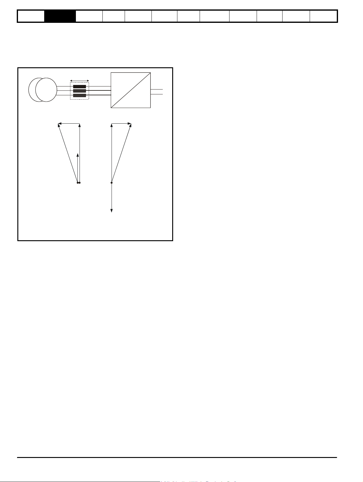
The following phasor diagram illustrates the relationship between the
supply voltage and the Regen drive voltage. The angle between the two
voltage vectors is approximately 5° at full load, this results in a near unity
power factor of 0.996.
Figure 2-1
AC
U
V
W
+DC
-DC
DC
VAC
JLIrω
V
s
V
r
I
r
Supply
jLIrω
V
V
s
r
I
r
Power flow
from supply
V
Supply voltage
s
V Voltage at line terminals of Regen drive
r
j LI Voltage across Regen inductor
ω
r
I Current at line terminals of Regen drive
r
jLIrω
V
r
Power flow
back to supply
I
r
V
s
The direction of the power flow can be changed relative to the supply
voltage, by making small changes to the Regen drives output voltage
and phase.
2.5 Synchronisation
The synchronisation of the Regen drive to the supply does not require
additional hardware. The space vector modulator within the Regen drive
represents the angle and magnitude of the AC supply at all times. This
however is not the case when the AC supply is first connected or when
the Regen drive is disabled.
Unless some form of synchronisation is carried out the current
controllers will start with values of zero resulting in zero volts being
applied to the inverter output terminals. The phase locked loop (PLL)
would also start with zero and so would not lock onto the supply.
To overcome these problems the following information must be obtained
before the Regen drive attempts to start:
1. The mains supply voltage vector magnitude
2. The angle of the supply voltage vector
3. The frequency of the supply
These values are obtained by carrying out a synchronisation on enable
• The first stage of the pre-start tests is to measure the initial DC Bus
voltage, which is assumed to be equal to the peak line-to-line
voltage of the supply.
• The second stage of the pre-start test is to apply two short pulses of
zero volts at the converter input. These pulses must be short enough
so that the peak current is less than the over current trip level of the
converter. The time between the pulses must also be long enough
so that the current built up in the input inductors during the first pulse
has decayed to a low level before the second pulse is applied.
These are used to calculate the instantaneous angle of the supply
voltage vector during the first test pulse. The second test pulse is
Getting
started
Optimisation Parameters
Te ch n ic al
data
Component
sizing
Diagnostics
then applied at time Td later to allow the supply frequency to be
calculated.
At this stage the supply inductance is also calculated
• Once the synchronization is complete the phase locked loop (PLL) is
set-up. At this point the whole control system could be started and
should operate without any large transients.
• To improve the robustness of the start-up phase a further short test
pulse voltage vector, with the same magnitude and phase as the
estimated supply voltage vector is applied. This is to detect
measurement errors that could have occurred because of supply
distortion present during the pre-start tests.
2.6 Current trimming
A current feedback trimming routine runs before the drive is enabled to
minimise offsets in the current feedback. This feature can be user
configured, for more details refer to section 8.5 Current trimming on
page 91.
2.7 Regen system configurations
The Regen drive has been designed to provide a regulated DC supply to
other motoring drives. The Regen drive gives bi-directional power flow
with sinusoidal currents and a near unity power factor.
Following are the possible configurations for Unidrive SP Regen:
• Single Regen, single or multiple motoring (Figure 4-1 on page 32)
• Single Regen, multiple motoring using a Unidrive SPMC (Figure 42 on page 34)
• Single Regen, multiple motoring using an external charging resistor
(Figure 4-3 on page 36)
• Multiple Regen, multiple motoring using a Unidrive SPMC (Figure 44 on page 38)
Refer to Table 3-2 on page 14, for the Regen drive ratings.
The sizing of a regen system must take into account the following
factors:
• Line voltage
• Motor rated current, rated voltage and power factor
• Maximum load power and overload conditions
In general, when designing a regen system, equal Regen and motoring
drive rated currents will work correctly. However, care must be taken to
ensure that under worst case supply conditions the Regen drive is able
to supply or absorb all the required power. In multi-drive configurations,
the Regen drive must be of a sufficient size to supply the net peak power
demanded by the combined load of all the motoring drives and total
system losses.
If the Regen drive is unable to supply the full power required by the
motoring drive, the DC bus voltage will drop and in severe cases may
lose synchronisation with the mains and trip. If the Regen drive is unable
to regenerate the full power from the motoring drive on the DC bus, then
the Regen and motoring drive(s) will trip on over-voltage.
8 Unidrive SP Regen Installation Guide
www.controltechniques.com Issue Number: 2
Page 9
Safety
Information
Introduction
Product
information
System
design
Mechanical
installation
Electrical
installation
Getting
started
Optimisation Parameters
Technical
data
Component
sizing
Diagnostics
2.8 Regen drive system types
2.8.1 Single Regen, single motoring system
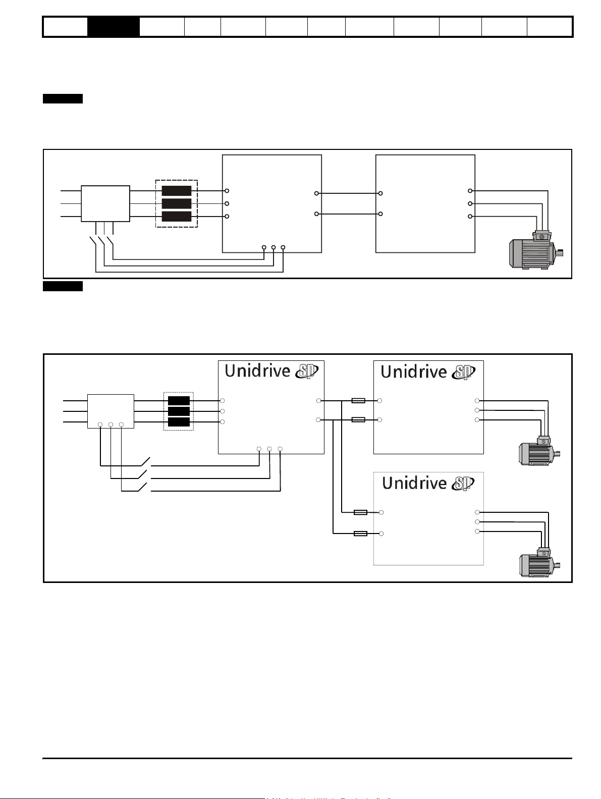
Figure 2-2 shows a typical layout for a standard regen system consisting of a single Regen drive and single motoring drive. In this configuration the
Regen drive is supplying the motoring drive and passing the regenerative energy back to the mains supply.
NOTE
The power up connections to L1, L2, L3 of the Regen drive are only made during power-up. Once both drives are powered up, this is switched out
and the main regen supply switched in. The auxiliary on the charging circuit to the Regen drive’s L1, L2, L3 connections for power up must be closed
(charging supply removed) before the Regen drive can be enabled.
Figure 2-2 Single Regen, single motoring system
Regen
inductor
L1
L2
Additional
circuitry
L3
U
Regen drive
U
AC supply
V
connection
W
L1
+DC
-DC
L2 L3
Common
DC bus
connections
U
Motoring drive
+DC
-DC
Motor
Connection
U
V
W
Power up only
NOTE
For the above single Regen, single motoring configuration; the Regen drive must be of the same frame size or larger.
2.8.2 Single Regen, multiple motoring system
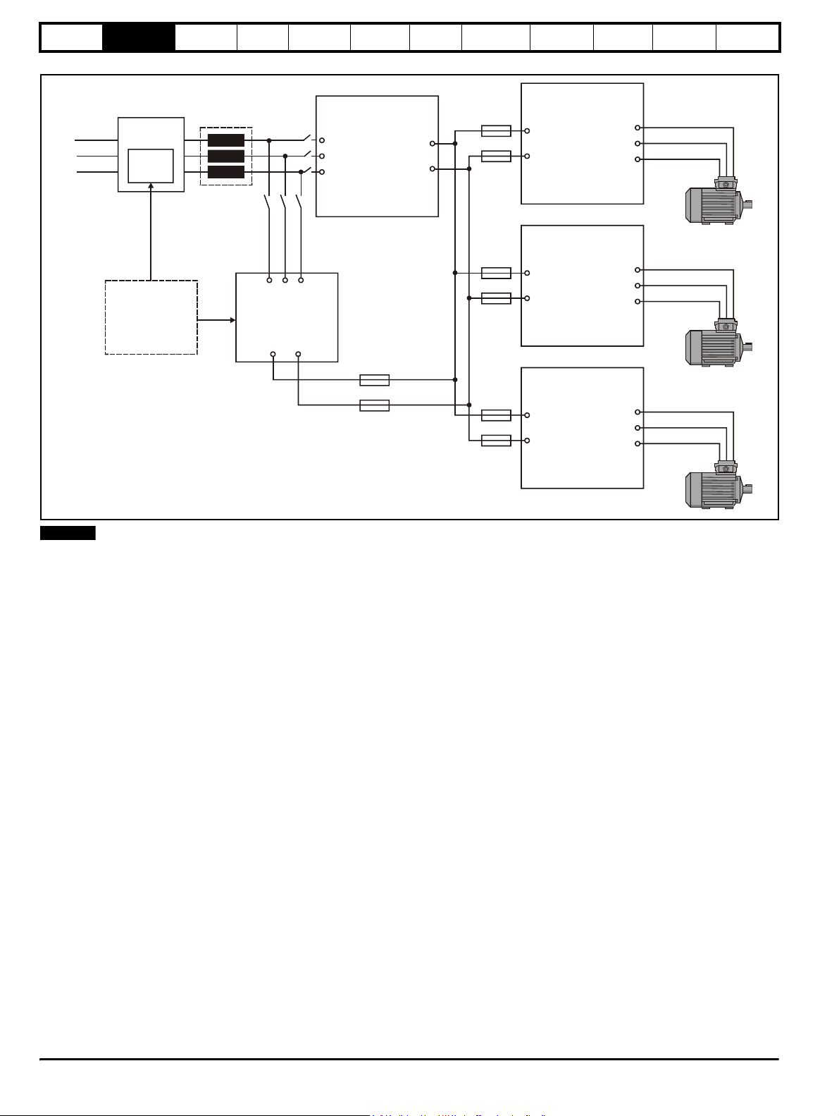
Figure 2-4 shows the layout for a regen system consisting of a single Regen drive with multiple motoring drives. In this configuration the Regen drive
is sized to the total power of all motoring drives.
Figure 2-3 Single Regen, multiple motoring system
Regen
Inductor
L1
L2
L3
Additional
Circuitry
Regen Drive
U
AC Supply
V
Connection
W
L1
+DC
-DC
L2 L3
DC Bus
Connections
Motoring Drive
+DC
-DC
Connection
Motor
U
V
W
Power up only
Motoring Drive
+DC
Connection
-DC
Motor
U
V
W
It is also possible to have a single Regen drive powering multiple motoring drives as shown with the power up connections also being provided via the
Regen drives L1, L2, L3 inputs and using the Regen drives own internal softstart.
In this arrangement the total capacitance of the motoring drives must not exceed the capacitance of the Regen drive, in cases where this does please
contact Technical Support.
Unid rive SP Regen Insta llation G uide 9
Issue Number: 2 www.controltechniques.com
Page 10
Safety
Information
Introduction
Product
information
System
design
Mechanical
installation
Figure 2-4 Single Regen, multiple motoring system
Electrical
installation
Getting
started
Optimisation Parameters
Te ch n ic al
data
Component
sizing
Diagnostics
Regen
Additional
L1
L2
L3
circuitry
External
charging
circuit
inductor
U
Regen drive
U
AC supply
V
connection
W
+DC
-DC
U
Motoring drive 1
+DC
-DC
connection
Motor
U
V
W
U
Motoring drive 2
Charging circuit can
consist of either
Unidrive SPMC
solution or external
charging circuit as
detailed in Chapter 4
System Design
L1 L2 L3
Unidrive
SPMC
+DC -DC
Common DC Bus
+DC
connection
-DC
connections
Motor
U
V
W
U
Motoring drive 3
+DC
connection
-DC
Motor
U
V
W
NOTE
For a single Regen and multiple motoring drive arrangement optional charging circuits can be used for the increased inrush current generated by the
additional capacitance of the multiple motoring drives. The charging circuit can consist of either a Unidrive SPMC rectifier module or an external
charging resistor as detailed in Chapter 4 System design
10 Unidrive SP Regen Installation Guide
www.controltechniques.com Issue Number: 2
Page 11
Safety
Information
Introduction
Product
information
System
design
Mechanical
installation
Electrical
installation
Getting
started
Optimisation Parameters
Technical
data
Component
sizing
Diagnostics
2.8.3 Multiple Regen, multiple motoring system
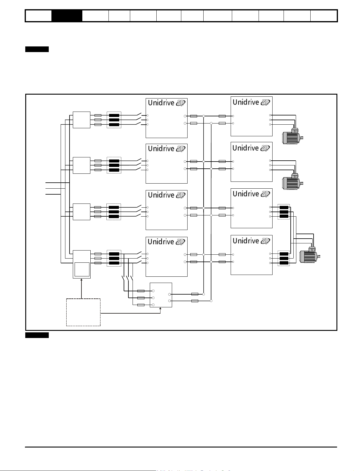
Figure 2-5 shows a multiple regen drive system with multiple motoring drives. For this configuration the regen drives are sized to the total power
requirement of all motoring drives.
NOTE
For the multiple regen and multiple motoring drives arrangement there are two possible options for the required start-up circuit. This can either consist
of a Unidrive SPMC rectifier module (for example an SPMC 1402 is capable of charging a maximum DC Bus capacitance of 66mF) or an external
charging resistor as detailed in Chapter 4 System design on page 30.
Special care should be taken when designing a multiple regen and multiple motoring drive system ensuring that all the required fusing is in place on
both the common DC Bus connections and the AC supply to all regen drives.
Figure 2-5 Multiple Regen, multiple motoring system
DC Bus
Additional
Circuitry
Regen Drive
U
V
W
+DC
-DC
Connections
Motoring Drive
Motor
Connection
U
V
W
+DC
-DC
Regen Drive
Additional
Circuitry
L1
L2
L3
Additional
Circuitry
Additional
Circuitry
External
charging
circuit
Charging circuit can
consist of either
Unidrive SPMC
solution or external
charging circuit
(Unidrive SPMC
recommended)
U
V
W
Regen Drive
U
V
W
Regen Drive
U
V
W
SPMC
L1
L2
L3
+DC
-DC
+DC
-DC
+DC
-DC
+DC
-DC
Motoring DriveMotoring Drive
+DC
-DC
Motor
Connection
U
V
W
Motoring DriveMotoring DriveMotoring DriveMotoring Drive
Motor
Connection
U
V
W
+DC
-DC
Motoring Drive
Motor
Connection
U
V
W
+DC
-DC
NOTE
All drives paralleled must be of the same frame size, and a derating also
applies as specified in Chapter 3 Product Information on page 12
Unidr ive SP Re gen Inst allatio n Guide 11
Issue Number: 2 www.controltechniques.com
Page 12
Safety
/
date code
Information
Introduction
Product
information
System
design
Mechanical
installation
Electrical
installation
Getting
started
Optimisation Parameters
3 Product Information
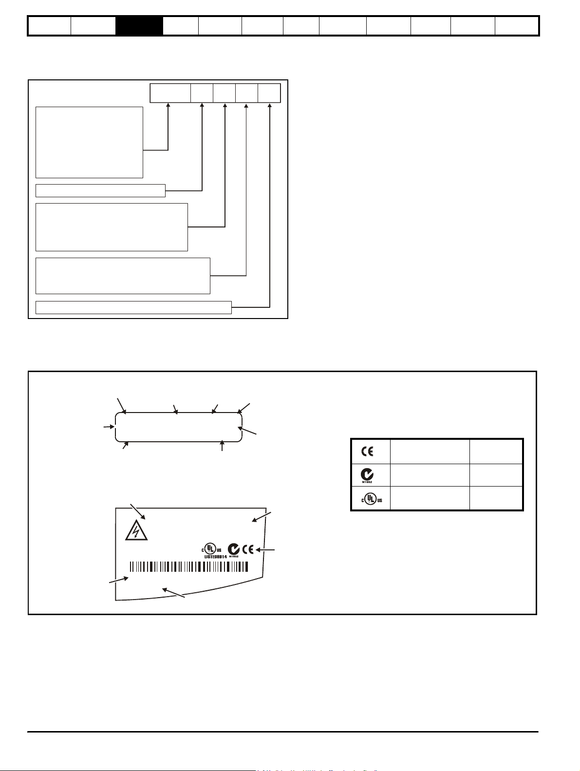
3.1 Model number
The way in which the model numbers for the Unidrive SP range are formed is illustrated below.
Technical
data
Component
sizing
Diagnostics
Unidrive SP product line
SP:
Solutions platform
complete inverter drive
Power module power stages
SPMA:
for custom drive systems AC input
SPMD:
Power module power stages
for custom drive systems DC input
SP frame size
Voltage rating
0:
Voltage independent
2:
200V to 240V
4:
380V to 480V
5:
500V to 575V
6:
500V to 690V
Configuration
Wall mount
0:
Wall mount, no dynamic brake control
2:
Stand alone, no dynamic brake control
3:
Current rating step
SPX
1 4 0 1
3.2 Nameplate description
See Figure 3-2 on page 17 for location of rating labels.
Figure 3-1 Typical drive rating labels
Rating label
Input voltage
rating
Model
Output voltage
range
Approvals label
I/P 200-240V 50-60Hz 3ph 6.6A
SP1201
O/P 0-240V 4.3 / 5.2A
Model
Please read manual before connecting.
Input
frequency
S.No:
3000005001
SP 1,5 TL
Heavy Duty / Normal Duty
rating output current
SP1201 0.75 / 1.1kW
Electric Shock Risk: Wait 10 min between
disconnecting supply & removing covers
SP 1,5 TL
IND.
CONT.
EQ.
No. of
phases
R
Typical input
current for
Normal Duty
rating
Serial
number
Heavy Duty
Normal Duty
power rating
Approvals
Key to approvals
CE approval Europe
C Tick approval Australia
UL / cUL approval
R
USA &
Canada
Serial
number
3000005001
STDL25
Made In U.K
Ser No:
Customer and
12 Unidrive SP Regen Installation Guide
www.controltechniques.com Issue Number: 2
Page 13
Safety
Information
Introduction
Product
information
System
design
Mechanical
installation
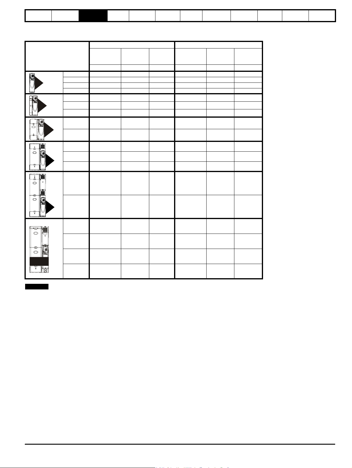
3.3 Ratings
Table 3-1 200V Drive ratings (200V to 240V ±10%)
Normal Duty Heavy Duty
Model
1201 5.2 1.1 1.5 4.3 0.75 1.0
1
2
3
4
1202 6.8 1.5 2.0 5.8 1.1 1.5
1203 9.6 2.2 3.0 7.5 1.5 2.0
1204 11 3.0 3.0 10.6 2.2 3.0
2201 15.5 4.0 5.0 12.6 3.0 3.0
2202 22 5.5 7.5 17 4.0 5.0
2203 28 7.5 10 25 5.5 7.5
3201 42 11 15 31 7.5 10
3202 54 15 20 42 11 15
4201 68 18.5 25 56 15 20
4202 80 22 30 68 18.5 25
4203 104 30 40 80 22 30
5201 130 37 50 105 30 40
Maximum
continuous
output current
AkWhpAkWhp
Nominal
power
at 220V
Electrical
installation
Motor
power
at 230V
Getting
started
Maximum
continuous
output current
Optimisation Parameters
Nominal
power
at 220V
Motor
power
at 230V
Technical
data
Component
sizing
Diagnostics
55
5202 154 45 60 130 37 50
1201 192 55 175 156 45 60
1202 248 75 100 192 55 75
1203 312 90 125 250 75 100
SPMD
1204 350 110 150 290 90 125
NOTE
The above current ratings are given for max 40°C (104°F), and 3.0 kHz
switching. Derating is required for higher switching frequencies, ambient
temperature >40°C (104°F) and high altitude. For further information,
refer to both the Unidrive SP and SPM User Guides.
Unidr ive SP Re gen Inst allatio n Guide 13
Issue Number: 2 www.controltechniques.com
Page 14
Safety
Information
Introduction
Product
information
System
design
Mechanical
installation
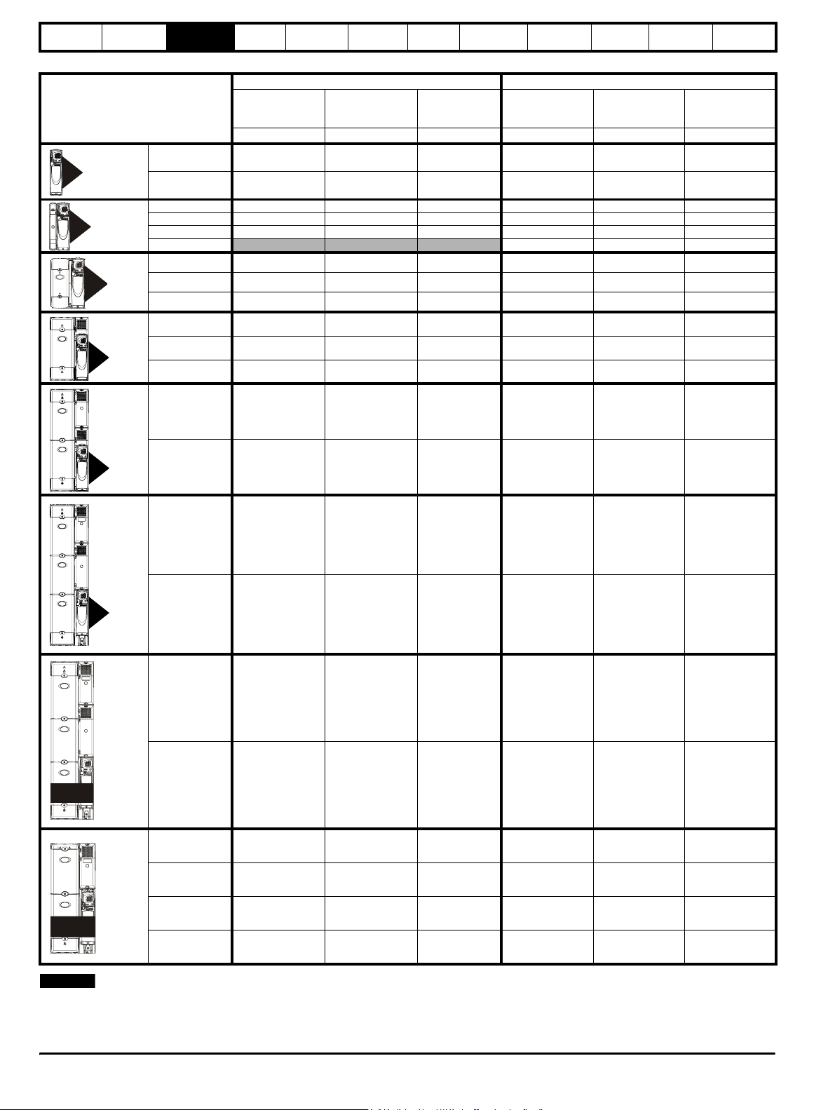
Table 3-2 400V drive ratings (380V to 480V ±10%)
Model
1405 8.8 4.0 5.0 7.6 3.0 5.0
1
2
3
1406 11 5.5 7.5 9.5 4.0 5.0
2401 15.3 7.5 10 13 5.5 10
2402 21 11 15 16.5 7.5 10
2403 29 15 20 25 11 20
2404
3401 35 18.5 25 32 15 25
3402 43 22 30 40 18.5 30
3403 56 30 40 46 22 30
4401 68 37 50 60 30 50
Maximum
continuous
input current
AkWhpAkWhp
Electrical
installation
Normal Duty Heavy Duty
Typical motor
power
at 400V
Getting
started
Typ i cal m o to r
power
at 460V
Optimisation Parameters
Maximum
continuous
input current
29 15 20
Technical
data
Typical motor
power
at 400V
Component
sizing
Diagnostics
Typical motor
power
at 460V
4
55
56
4402 83 45 60 74 37 60
4403 104 55 75 96 45 75
5401 138 75 100 124 55 100
5402 168 90 125 156 75 125
6401 202 110 150 180 90 150
6402 236 132 200 210 110 150
1401 205 110 150 180 90 150
SPMA
1402 236 132 200 210 110 150
1401 205 110 150 180 90 150
1402 246 132 200 210 110 150
1403 290 160 250 246 132 200
SPMD
1404 350 200 300 290 160 250
NOTE
The SPMD1404 can deliver 350A continuously only if the ambient is 35°C or lower and it is docked to the SPMC. Under all other circumstances the current rating is 335A.
The above current ratings are given for max 40°C (104°F), and 3.0 kHz switching. Derating is required for higher switching frequencies, ambient
temperature >40°C (104°F) and high altitude. For further information, refer to both the Unidrive SP and SPM User Guides.
14 Unidrive SP Regen Installation Guide
www.controltechniques.com Issue Number: 2
Page 15
Safety
Information
Introduction
Product
information
System
design
Mechanical
installation
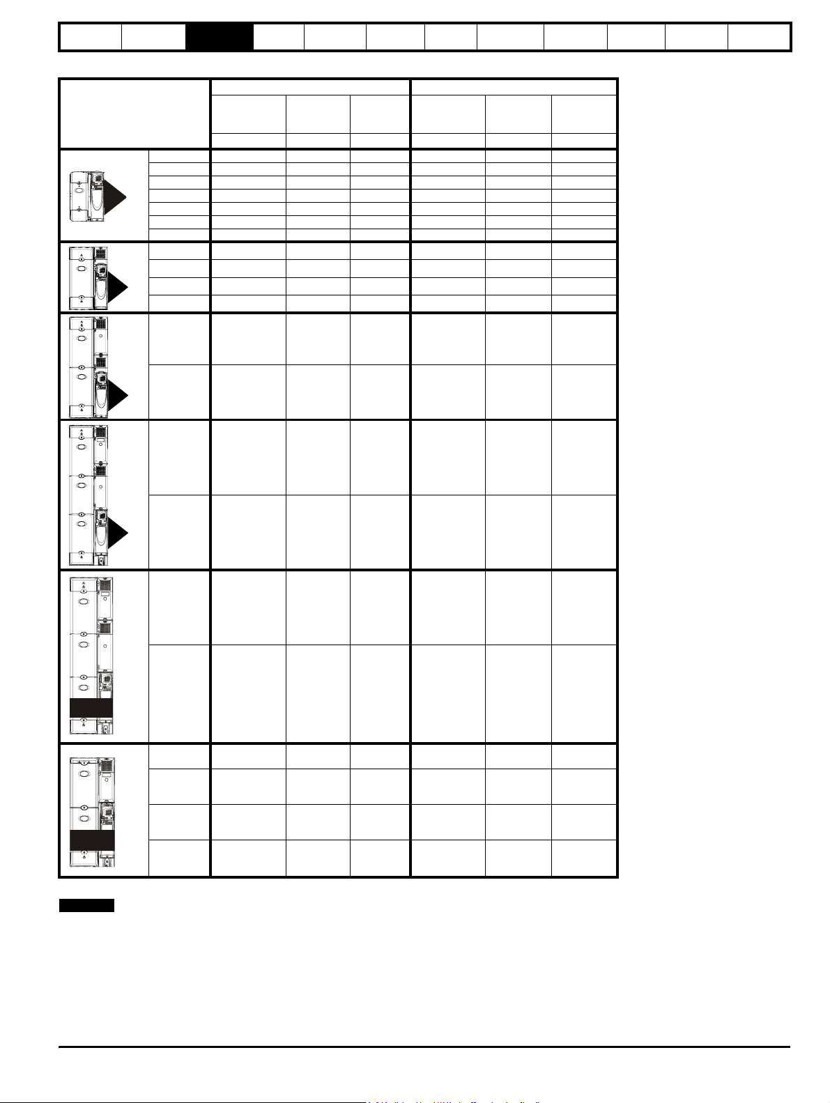
Table 3-3 575V Drive ratings (500V to 575V ±10%)
Normal Duty Heavy Duty
3
4
Model
Maximum
continuous
output current
AkWhpAkWhp
3501 5.4 3.0 3.0 4.1 2.2 2.0
3502 6.1 4.0 5.0 5.4 3.0 3.0
3503 8.4 5.5 7.5 6.1 4.0 5.0
3504 11 7.5 10 9.5 5.5 7.5
3505 16 11 15 12 7.5 10
3506 22 15 20 18 11 15
3507 27 18.5 25 22 15 20
4603 36 22 30 27 18.5 25
4604 43 30 40 36 22 30
4605 52 37 50 43 30 40
4606 62 45 60 52 37 50
5601 84 55 75 63 45 60
Nominal
power
at 575V
Electrical
installation
Motor
power
at 575V
Getting
started
Maximum
continuous
output current
Optimisation Parameters
Nominal
power
at 575V
Motor
power
at 575V
Technical
data
Component
sizing
Diagnostics
SPMA
55
56
5602 99 75 100 85 55 75
6601 125 90 125 100 75 100
6602 144 110 150 125 90 125
1601 125 90 125 100 75 100
1602 144 110 150 125 90 125
1601 125 110 150 100 90 125
1602 144 132 175 125 110 150
1603 168 160 200 144 132 175
SPMD
1604 192 185 250 168 160 200
The power ratings above for model size 4 and larger are for the 690V drives when used on a 500V to 575V supply.
NOTE
The above current ratings are given for max 40°C (104°F), and 3.0 kHz switching. Derating is required for higher switching frequencies, ambient
temperature >40°C (104°F) and high altitude. For further information, refer to both the Unidrive SP and SPM User Guides.
Unidr ive SP Re gen Inst allatio n Guide 15
Issue Number: 2 www.controltechniques.com
Page 16

Safety
Information
Introduction
Product
information
System
design
Table 3-4 690V Drive ratings (690V ±10%)
Maximum
continuous
output current
AkWhpAkWhp
4
Model
4601 22 18.5 25 19 15 20
4602 27 22 30 22 18.5 25
4603 36 30 40 27 22 30
4604 43 37 50 36 30 40
4605 52 45 60 43 37 50
4606 62 55 75 52 45 60
5601 84 75 100 63 55 75
Mechanical
installation
Normal Duty Heavy Duty
Nominal
power
at 690V
Electrical
installation
Motor
power
at 690V
Getting
started
Maximum
continuous
output current
Optimisation Parameters
Nominal
power
at 690V
Motor
power
at 690V
Technical
data
Component
sizing
Diagnostics
SPMA
55
56
5602 99 90 125 85 75 100
6601 125 110 150 100 90 125
6602 144 132 175 125 110 150
1601 125 110 150 100 90 125
1602 144 132 175 125 110 150
1601 125 110 150 100 90 125
1602 144 132 175 125 110 150
1603 168 160 200 144 132 175
SPMD
1604 192 185 250 168 160 200
NOTE
The above current ratings are given for max 40°C (104°F), and 3.0 kHz switching. Derating is required for higher switching frequencies, ambient
temperature >40°C (104°F) and high altitude. For further information, refer to both the Unidrive SP and SPM User Guides.
16 Unidrive SP Regen Installation Guide
www.controltechniques.com Issue Number: 2
Page 17
Safety
A
±
r
A
Information
Introduction
Product
information
System
design
3.4 Drive features
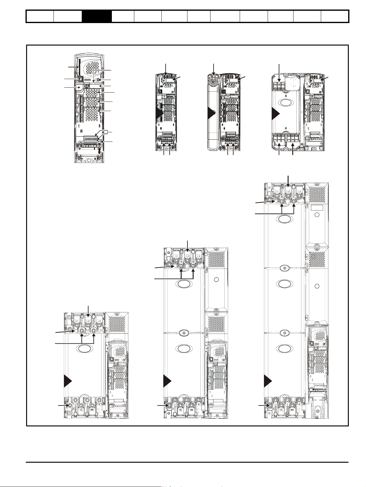
Figure 3-2 Features of the drive sizes 1 to 6
SMARTCARD
slot
Keypad
connection
Serial port
connector
Approvals label
Status LED
Rating label
Solutions Module
slot 1
Solutions Module
slot 2
Solutions Module
slot 3
Mechanical
installation
±
Electrical
installation
DC Bus output
(High current)
1
EMC
capacitor
must be
removed
Getting
started
Optimisation Parameters
DC Bus output
(High current)
2
EMC
capacitor
must be
removed
Technical
data
±
DC Bus output
(High current)
3
3
Component
sizing
Diagnostics
EMC
capacito
must be
removed
Charging input
(L1, L2, L3)
Control terminals
Relay terminals
EMC capacitor
±
DC Bus output
(High current)
Charging input
(L1, L2, L3)
must be
removed
AC supply
(U, V, W)
Charging input
(L1, L2, L3)
Charging input
(L1, L2, L3)
AC supply
(U, V, W)
EMC capacitor
must be
removed
±
DC Bus output
(High current)
Charging input
(L1, L2, L3)
(U, V, W)
Charging input
(L1, L2, L3)
C supply
EMC capacitor
must be
removed
±
DC Bus output
(High current)
AC supply
(U, V, W)
4
AC supply
(U, V, W)
5
C supply
(U, V, W)
6
Unidr ive SP Re gen Inst allatio n Guide 17
Issue Number: 2 www.controltechniques.com
Page 18
Safety
y
Information
Introduction
Product
information
System
design
Mechanical
installation
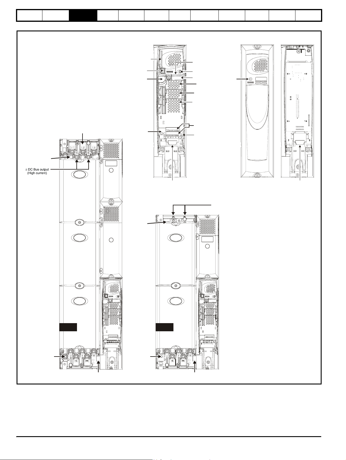
Figure 3-3 Features of the drive sizes SPMA and SPMD
SMARTCARD
slot
Keypad
connection
Serial port
connector
Electrical
installation
Getting
started
Optimisation Parameters
Technical
data
Master interface Slave interface
Cover Base
Approvals label B
Status LED
Rating label
Solutions Module
slot 1
Solutions Module
slot 2
Solutions Module
slot 3
Stat us
LED
Component
sizing
Diagnostics
EMC capacitor
must be removed
Charging input
(L1, L2, L3)
Encoder
connection
EMC capacitor
must be removed
Output connections
to slave
Control terminals
Relay terminals
±
(high current)
DC Bus output
Input from Master /
Output to slave
SPMA SPMD
AC supply
(U, V, W)
Heatsink fan
supply connections
AC supply
(U, V, W)
Heatsink fan
suppl
connections
18 Unidrive SP Regen Installation Guide
www.controltechniques.com Issue Number: 2
Page 19
Safety
Information
Introduction
Product
information
System
design
Mechanical
installation
Electrical
installation
Getting
started
Optimisation Parameters
3.5 Unidrive SPMC half controlled thyristor rectifier
NOTE
For the 200V modules where an external charging circuit is required the
SPMU1401, SPMU1402 and SPMU2402 can be used as detailed
following:
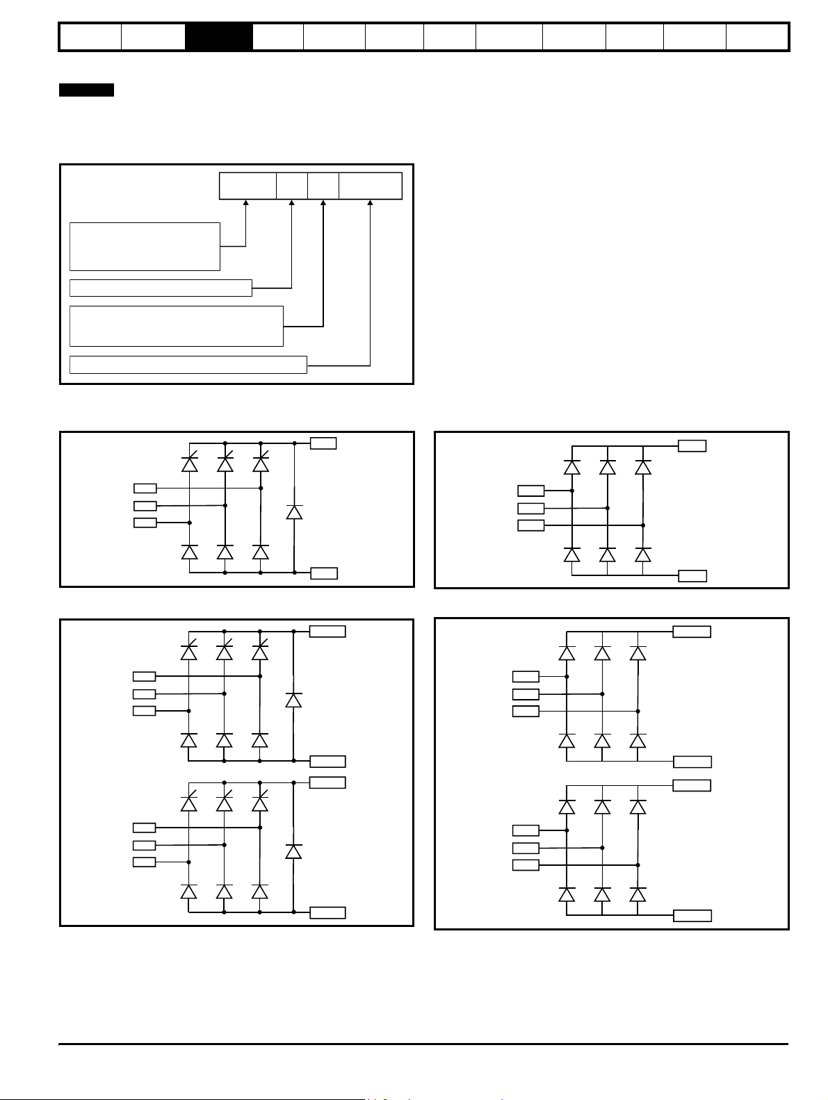
Figure 3-4 Rectifier (SPMC and SPMU)
SPMC 1 402
Unidrive SPM product line
Controlled rectifier
SPMC:
SPMU:
Uncontrolled rectifier
Number of rectifier stages
Vol tag e rat i ng
4: 380V to 480V
6: 500V to 690V
Current rating step
The Unidrive SPMC is a controlled thyristor rectifier and the SPMU is an uncontrolled rectifier.
SPMC1402 and 1601
Figure 3-5 Single half controlled thyristor
+DC
SPMU1401, 1402 and 1601
Figure 3-7 Single diode rectifier
Technical
data
Component
sizing
+DC
Diagnostics
L1
L2
L3
SPMC2402 and 2601
Figure 3-6 Dual half controlled thyristor
L1A
L2A
L3A
L1B
L2B
L3B
-DC
+DC (A)
-DC (A)
+DC (B)
L1
L2
L3
-DC
SPMU2402 and 2601
Figure 3-8 Dual diode rectifier
+DC (A)
L1A
L2A
L3A
-DC (A)
+DC (B)
L1B
L2B
L3B
-DC(B)
-DC (B)
The Unidrive SPMC is a half controlled thyristor bridge is used as a front end to the SPMD inverter module or as a stand alone rectifier for several
smaller drives. Soft-start is built in.
The Unidrive SPMU is used as a front end to the SPMD inverter module or as a stand alone rectifier for several smaller drives. Softstart must be
supplied externally using a resistor and contactor or SPMC.
An external 24V, 3A power supply is required in addition to the AC supply to allow the rectifier to operate. Control wiring is required between the
rectifier and motoring drive(s) so that if the rectifier indicates a fault the motoring drive(s) will be disabled.
Unidr ive SP Re gen Inst allatio n Guide 19
Issue Number: 2 www.controltechniques.com
Page 20

Safety
Information
Introduction
Product
information
System
design
Mechanical
installation
Electrical
installation
Getting
started
Optimisation Parameters
Technical
data
Component
sizing
Diagnostics
The 24V supply must be protected using a 4A slow-blow fuse, one for each supply pole.
Control connections to the Unidrive SPMC/U should be made with 0.5mm2 cable.
The status relay contacts are rated for switching non-inductive loads at 250Vac 6A non-inductive, up to 4Adc if the voltage is limited to 40V or up to
400mA dc if the voltage is limited to 250Vdc. Protection from overcurrent must be provided.
Figure 3-9 SPMC/U rating label
Input voltage, frequency,
no. of phases and current
Approvals
Serial
number
STDN39
Customer and
date code
Status1 Status0
Status
LEDs
I/P 380-480V 50-60Hz 3ph 204A
O/P 513-648V 552A
Output voltage
and current
Model:
SPMC = Controlled
SPMU = Uncontrolled
SPMC1402
Number of
rectifier
stages
Ser No: 3000005001
Voltage
rating:
4 - 400V
6 - 690V
Indicates
sub-rating
within frame
size
3.6 Unidrive SPMC/U technical data
Table 3-5 Unidrive SPMC / U input current, fuse and cable ratings
Semi-conductor fuse
in series with HRC fuse
HRC IEC
class gG UL
class J
Semi-
conductor
IEC class aR
mm
Model
Typical input
current
A
Maximum
input current
A
Typical DC
current
Adc
SPMC1402 339 344 379 540 400 2 x 120 2 x 4/0 2 x 120 2 x 4/0
SPMC2402 2 x 308 2 x 312 2 x 345 450 400 2 x 120 2 x 4/0 2 x 120 2 x 4/0
SPMU1401 207 210 222 250 315 2 x 70 2 x 2/0 2 x 70 2 x 2/0
SPMU1402 339 344 379 540 400 2 x 120 2 x 4/0 2 x 120 2 x 4/0
SPMU2402 2 x 339 609 2 x 379 450 400 2 x 120 2 x 4/0 2 x 120 2 x 4/0
SPMC1601 192 195 209 250 250 2 x 70 2 x 2/0 2 x 120 2 x 4/0
SPMC2601 2 x 170 2 x 173 2 x 185 250 250 2 x 70 2 x 2/0 2 x 120 2 x 4/0
SPMU1601 192 195 209 250 250 2 x 70 2 x 2/0 2 x 120 2 x 4/0
SPMU2601 2 x 170 2 x 173 2 x 185 250 250 2 x 70 2 x 2/0 2 x 120 2 x 4/0
Cable sizes
AC input DC output
2
AWG
mm
2
AWG
The user must provide a means of preventing live parts from
being touched. A cover around the electrical connections at
the top of the inverter and the bottom of the rectifier where the
WARNING
cables enter is required.
Input fuses as specified must be provided.
WARNING
The Unidrive SPMC/U depends on the drive for protection.
Status outputs must be linked to the drive enable regen
drive(s) and circuit to ensure that when the rectifier indicates
WARNING
a fault the motoring drive(s) are disabled.
20 Unidrive SP Regen Installation Guide
www.controltechniques.com Issue Number: 2
Page 21
Safety
Information
Introduction
Product
information
System
design
Mechanical
installation
Electrical
installation
Getting
started
Optimisation Parameters
Technical
data
Component
sizing
Diagnostics
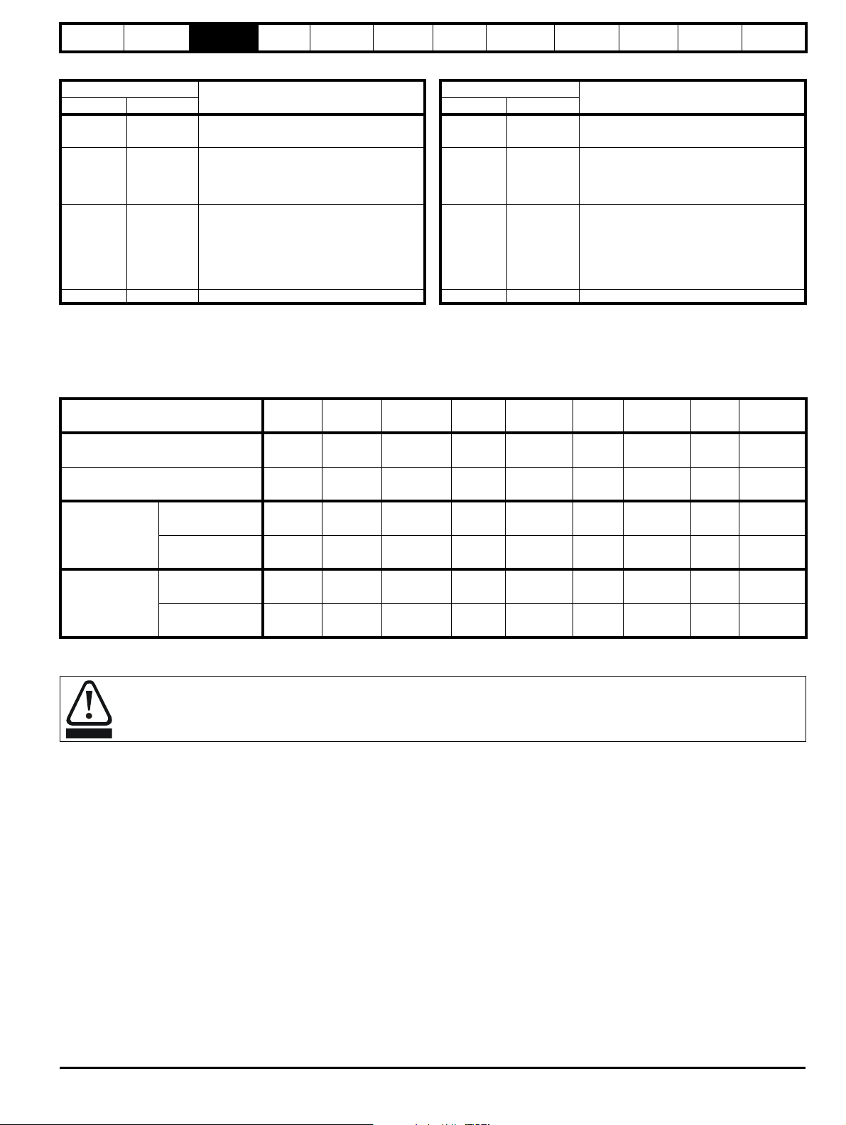
Table 3-6 Key to Unidrive SPMC (rectifier) LEDs Table 3-7 Key to Unidrive SPMU (rectifier) LEDs
Status Output
1: Left LED
OFF OFF
0: Right LED
Definition
Mains loss or 24V supply to the rectifier has
been lost
Status Output
1: Left LED
0: Right LED
Definition
OFF OFF 24V supply to the rectifier has been lost
Any of the following:
OFF ON Phase loss OFF ON
• Internal fault
• Check that rectifier is an SPMU. This
could indicate that unit is an SPMC
Any of the following:
Any of the following:
• Rectifier heatsink over temperature
• Rectifier PCB over temperature
• Status input wire break
ON OFF
• Snubber overheating due to excessive
cable charging current or supply notching
• Rectifier heatsink over temperature
• Rectifier PCB over temperature
ON OFF
• Status input wire break
ON ON System healthy ON ON System healthy
The half controlled thyristor rectifier can be used as an external charging module for a regen system consisting of multiple drives. The required
softstart function is built into the SPMC module as standard. An external 24V, 3A power supply is required in addition to the AC supply for the SPMC
to allow the rectifier to operate. Control wiring is required between the rectifier and drive(s) so that if the rectifier indicates a fault all drive(s) will be
disabled.
Table 3-8 SPM rectifier charging data
Model
AC line current
(100% Normal Duty Motor Current)
DC link current
(100% Normal Duty Motor Current)
Maximum
DC bus
capacitance on
a supply <25kA
Maximum
DC bus
capacitance on
a supply <25kA
Max capacitance
(mF)
When used with
line reactor
Max capacitance
(mF)
When used with
line reactor
SPMU
1401
207 339 677 339 677 192 385 192 385
222 379 758 379 758 209 418 209 418
44 66 132 66 132 29.3 59 29.3 59
INL401 INL402 2 x INL402 INL402 2 x INL402 INL602 2 x INL602 INL602 2 x INL602
44 66 66 66 66 29.3 29.3 29.3 29.3
INL401 INL402 INL412 INL402 INL412 INL602 INL612 INL602 INL612
SPMU
1402
SPMU
2402
SPMC
1402
SPMC
2402
SPMU
1601
SPMU
2601
SPMC
1601
SPMC
2601
Also refer to the Unidrive SPM User Guide for further detailed information on the Unidrive SPMC mechanical and electrical installation.
• The user must provide a means of preventing live parts from being touched. A cover around the electrical connections at the top of
the inverter and the bottom of the rectifier where the cables enter is required.
WARNING
• Fusing as specified must be provided.
Unidr ive SP Re gen Inst allatio n Guide 21
Issue Number: 2 www.controltechniques.com
Page 22
Safety
Information
Introduction
Product
information
System
design
Mechanical
installation
Electrical
installation
Getting
started
Optimisation Parameters
Technical
data
Component
sizing
Diagnostics
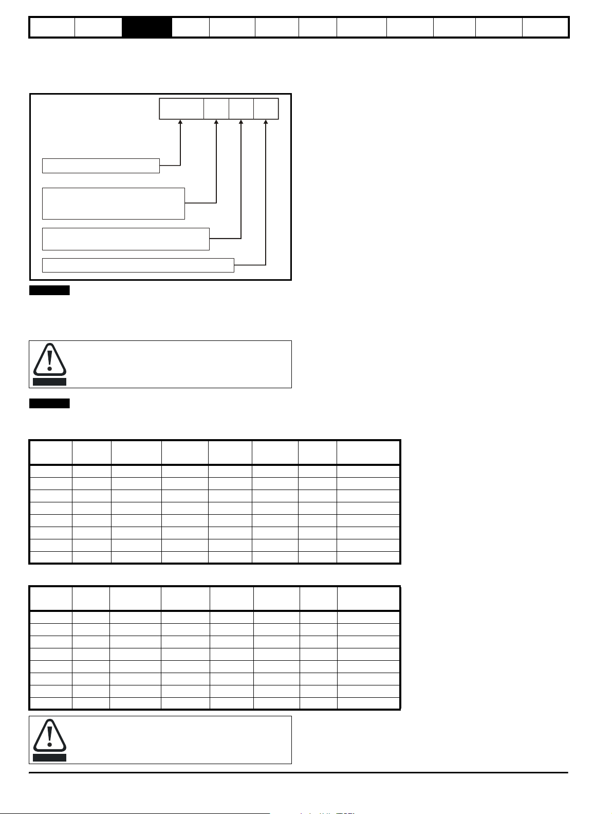
3.7 Output Sharing Chokes (for motoring drives only)
The following section covers the output sharing chokes which are currently available for Unidrive SP. These being used for the motoring drives in a
regen system only (between drive and motor).
Figure 3-10 Output sharing choke identification
OTL:
Output sharing choke
Voltage rating
4: 380V to 480V
6: 500V to 690V
0: Single
1: Dual
Current rating step
NOTE
OTL
4 0 1
For the 200V SPMx modules used in parallel configurations and where output sharing chokes are required the 400V OTL output sharing chokes
should be used.
The following tables detail the output chokes required for the various configurations of paralleled SPMA and SPMD power modules.
When connecting either SPMA or SPMD drives in parallel
they must be de-rated by 5%
CAUTION
NOTE
In order to achieve the best possible current sharing between paralleled Unidrive SPM modules, sharing chokes must be fitted.
Table 3-9 400 / 600V output sharing choke ratings
Model
CurrentAInductanceµHWidth (W)mmDepth (D)mmHeight (H)mmWeight
kg
Part No.
OTL401 221 40.1 240 220 210 20 4401-0197-00
OTL402 267 34 242 220 205 20 4401-0198-00
OTL403 313 28.5 242 220 205 25 4401-0199-00
OTL404 378 23.9 242 220 205 25 4401-0200-00
OTL601 135 103.9 242 170 203 20 4401-0201-00
OTL602 156 81.8 242 170 203 20 4401-0202-00
OTL603 181 70.1 242 200 203 20 4401-0203-00
OTL604 207 59.2 242 200 203 20 4401-0204-00
Table 3-10 400 / 600V centre tapped output sharing choke ratings
Model
CurrentAInductanceµHWidth (W)mmDepth (D)mmHeight (H)mmWeight
kg
Part No.
OTL411 389.5 42.8 300 150 160 8 4401-0188-00
OTL412 470.3 36.7 300 150 160 8 4401-0189-00
OTL413 551 31.1 300 150 160 8 4401-0192-00
OTL414 665 26.6 300 150 160 9 4401-0186-00
OTL611 237.5 110.4 300 150 160 8 4401-0193-00
OTL612 273.6 88.4 300 150 160 8 4401-0194-00
OTL613 319.2 76.7 300 150 160 8 4401-0195-00
OTL614 364.8 65.7 300 150 160 8 4401-0196-00
The OTLX1X centre tapped output sharing chokes can only
be used when two Unidrive SPM drives are paralleled
together. For all other combinations the OTLX0X output
CAUTION
sharing choke must be used.
22 Unidrive SP Regen Installation Guide
www.controltechniques.com Issue Number: 2
Page 23

Safety
Information
Introduction
Product
information
System
design
Mechanical
installation
3.8 Options
Figure 3-11 Options available for Unidrive SP Regen
SMARTCARD*
Electrical
installation
Getting
started
Keypad
Optimisation Parameters
Technical
Automation Fieldbus
data
Component
sizing
Diagnostics
External
footprint /
bookcase
CT Comms
cable
EMC filter
* A SMARTCARD is provided with the Unidrive SP as standard. Only one SMARTCARD can be fitted at any one time.
NOTE
Position feedback modules will still function with a drive configured in regen mode, however, this would only be required where the Regen drive is to
be used to provide additional Solutions Module slots for the motoring drive.
Unidr ive SP Re gen Inst allatio n Guide 23
Issue Number: 2 www.controltechniques.com
Page 24
Safety
Information
Introduction
Product
information
System
design
Mechanical
installation
Electrical
installation
Getting
started
Optimisation Parameters
Technical
data
Component
sizing
Diagnostics
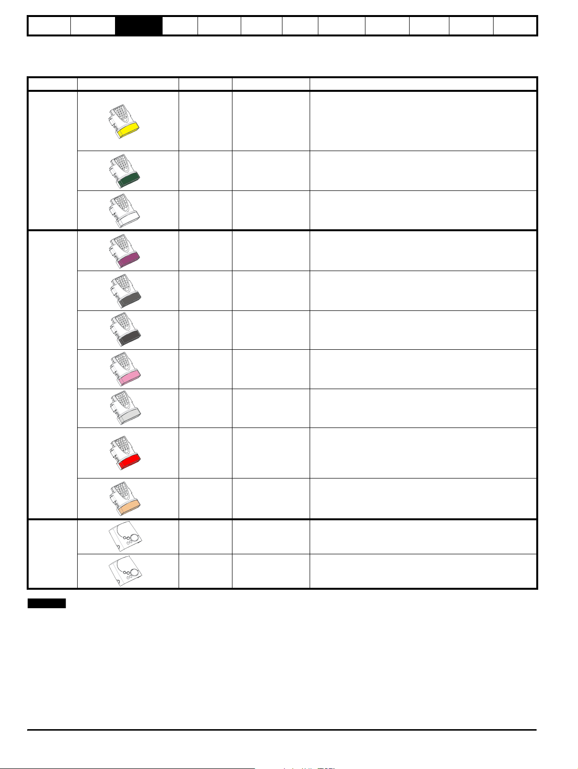
All Unidrive SP Solutions Modules are colour-coded in order to make identification easy. The following table shows the colour-code key and gives
further details on their function.
Table 3-11 Solutions Module identification
Type Solutions Module Colour Name Further Details
Extended I/O interface
Increases the I/O capability by adding the following to the
Yellow SM-I/O Plus
existing I/O in the drive:
• digital inputs x 3
• analogue output (voltage) x 1
• digital I/O x 3 • relay x 2
• analogue inputs (voltage) x 2
Automation
Fieldbus
Dark Green SM-Applications
White SM-Applications Lite
Purple SM-PROFIBUS-DP
Medium Grey SM-DeviceNet
Dark Grey SM-INTERBUS
Pink SM-CAN
Light Grey SM-CANopen
Red SM-SERCOS
Beige SM-Ethernet
Applications Processor (with CTNet)
nd
2
processor for running pre-defined and /or customer created
application software with CTNet support
Applications Processor
nd
2
processor for running pre-defined and /or customer created
application software
Profibus option
PROFIBUS DP adapter for communications with the Unidrive
SP.
DeviceNet option
Devicenet adapter for communications with the Unidrive SP
Interbus option
Interbus adapter for communications with the Unidrive SP
CAN option
CAN adapter for communications with the Unidrive SP
CANopen option
CANopen adapter for communications with the Unidrive SP
SERCOS option
Class B compliant. Torque velocity and position control modes
supported with data rates (bit/sec): 2MB, 4MB, 8MB and 16MB.
Minimum 250µsec network cycle time. Two digital high speed
probe inputs 1µsec for position capture
Ethernet option
10 base-T / 100 base-T; Supports web pages, SMTP mail and
multiple protocols: DHCP IP addressing; Standard RJ45
connection
N/A SM-Keypad
LED keypad option
Keypad with a LED display
Keypad
N/A SM-Keypad Plus
NOTE
Position feedback modules will still function with a drive configured in
LCD keypad option
Keypad with an alpha-numeric LCD display with Help function
regen mode, however, this would only be required where the Regen
drive is to be used to provide additional Solutions Module slots for the
motoring drive.
24 Unidrive SP Regen Installation Guide
www.controltechniques.com Issue Number: 2
Page 25
Safety
Information
Introduction
Product
information
System
design
Mechanical
installation
Electrical
installation
Getting
started
Optimisation Parameters
Technical
data
Component
sizing
Diagnostics
3.9 Items supplied with the drive
The drive is supplied with a copy of the Unidrive SP Short Form Guide, a
SMARTCARD, the safety booklet, the certificate of quality, an accessory
kit box (see the Unidrive SP User Guide for details) and a CD ROM
containing the following user guides:
• Unidrive SP User Guide (English, French, German, Italian, Spanish)
• Unidrive SP Advanced User Guide
• Unidrive SP Regen Installation Guide
• Solutions Module User Guides
• Unidrive SPM User Guide
3.10 Regen components
3.10.1 Regen inductor
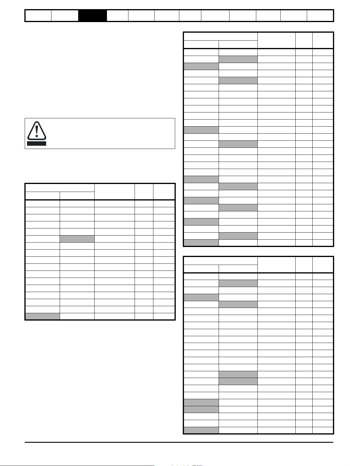
The following regen inductors are special parts being
designed for very high levels of harmonic voltage and having
a high saturation current with good linearity below saturation.
CAUTION
The regen inductor supports the difference between the PWM voltage
from the Unidrive SP Regen drive and sinusoidal voltage from the
supply.
Table 3-12 200V (200V to 240V ± 10%) Regen Inductors
Heavy Duty Normal Duty
SPMD1201 SP5202 4401-0321 0.22 156.0
SPMD1202 SPMD1201 4401-0322 0.18 192.0
SPMD1203 SPMD1202 4401-0323 0.14 250.0
SPMD1204 SPMD1203 4401-0324 0.11 312.0
Under no circumstances must a part be used other than
those listed.
Drive
Part number mH Arms
SP1203 SP1203 4401-0310 3.50 9.6
SP1204 SP1204 4401-0311 2.70 11.0
SP2201 SP2201 4401-0312 2.20 15.5
SP2202 SP2202 4401-0313 1.60 22.0
SP2203 SP2203 4401-0314 1.10 31.0
SP3201
4401-0314 1.10 31.0
SP3202 SP3201 4401-0315 0.81 42.0
SP4201 SP3202 4401-0316 0.60 56.0
SP4202 SP4201 4401-0317 0.50 68.0
SP4203 SP4202 4401-0318 0.40 80.0
SP5201 SP4203 4401-0319 0.32 105.0
SP5202 SP5201 4401-0320 0.26 130.0
SPMD1204 4401-0325 0.10 350.0
Table 3-13 400V (380V to 480V ± 10%) Regen Inductor
Drive
Heavy Duty Normal Duty
Part number mH Arms
SP1405 SP1405 4401-0001 6.30 9.5
SP1406
4401-0001 6.30 9.5
SP1406 4401-0002 5.00 12.0
SP2401 SP2401 4401-0003 3.75 16.0
SP2402
4401-0003 3.75 16.0
SP2403 SP2402 4401-0004 2.40 25.0
SP2404 SP2403 4401-0005 1.76 34.0
SP3401 SP2404 4401-0005 1.76 34.0
SP3402 SP3401 4401-0006 1.50 40.0
SP3403 SP3402 4401-0007 1.30 46.0
SP4401 SP3403 4401-0008 1.00 60.0
SP4401 4401-0009 0.78 70.0
SP4402 SP4402 4401-0010 0.63 96.0
SP4403
4401-0010 0.63 96.0
SP5401 SP4403 4401-0011 0.48 124.0
SP5402 SP5401 4401-0012 0.38 156.0
SP6401 SP5402 4401-0013 0.33 180.0
SP6402 SP6401 4401-0014 0.30 200.0
SP6402 4401-0015 0.20 300.0
SPMA1401
4401-0013 0.33 180.0
SPMA1402 SPMA1401 4401-0014 0.30 200.0
SPMA1402 4401-0015 0.20 300.0
SPMD1401
4401-0013 0.33 180.0
SPMD1402 SPMD1401 4401-0014 0.30 200.0
SPMD1402 4401-0015 0.20 300.0
SPMD1403 SPMD1403 4401-0015 0.20 300.0
SPMD1404
4401-0015 0.20 300.0
SPMD1404 4401-0205-00 0.16 350.0
Table 3-14 575V (500V to 575V ± 10%) Regen Inductor
Drive
Heavy Duty Normal Duty
Part number mH Arms
SP3505 SP3505 4401-0210 5.30 19.0
SP3506
4401-0211 4.60 22.0
SP3507 SP3506 4401-0212 3.80 27.0
SP3507 4401-0212 3.80 27.0
SP4601
4401-0211 4.60 22.0
SP4602 SP4601 4401-0212 3.80 27.0
SP4603 SP4602 4401-0212 3.80 27.0
SP4604 SP4603 4401-0213 2.80 36.0
SP4605 SP4604 4401-0214 2.40 43.0
SP4606 SP4605 4401-0215 1.90 52.0
SP5601 SP4606 4401-0216 1.60 63.0
SP5602 SP5601 4401-0217 1.20 85.0
SP6601 SP5602 4401-0218 1.00 100.0
SP6602 SP6601 4401-0219 0.80 125.0
SPMA1601
SPMD1601
4401-0218 1.00 100.0
4401-0218 1.00 100.0
SPMA1602 SPMA1601 4401-0219 0.80 125.0
SPMD1602 SPMD1601 4401-0219 0.80 125.0
SPMA1602 4401-0220 0.70 144.0
SPMD1602 4401-0220 0.70 144.0
SPMD1603 SP6602 4401-0220 0.70 144.0
SPMD1604 SPMD1603 4401-0221 0.60 168.0
SPMD1604 4401-0222 0.53 192.0
Unidr ive SP Re gen Inst allatio n Guide 25
Issue Number: 2 www.controltechniques.com
Page 26
Safety
Information
Introduction
Product
information
System
design
Mechanical
installation
Electrical
installation
Getting
started
Optimisation Parameters
Technical
data
Component
sizing
Diagnostics
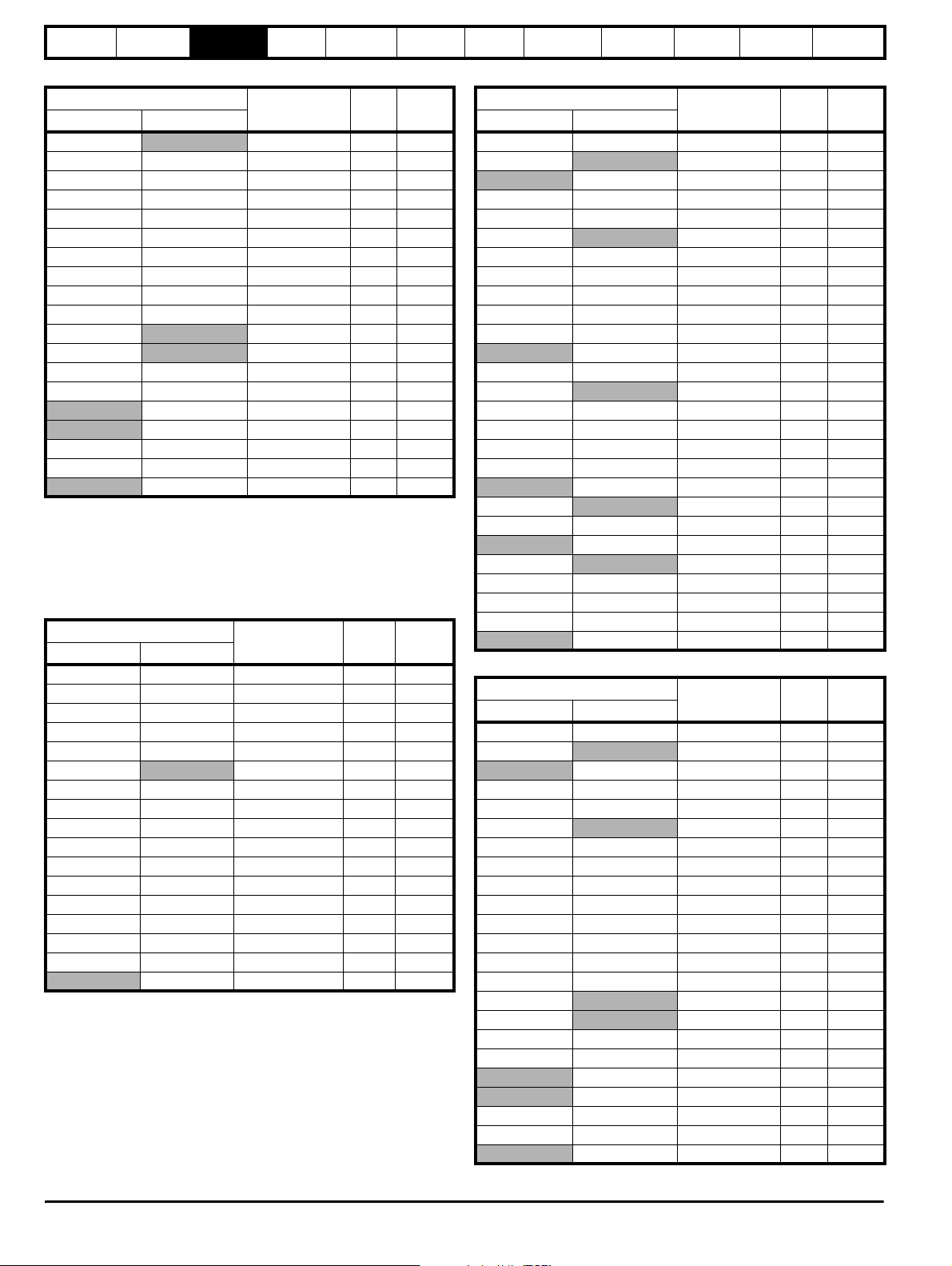
Table 3-15 690V (690V ± 10%) Regen Inductor
Drive
Heavy Duty Normal Duty
SP4601
Part number mH Arms
4401-0210 5.30 19.0
SP4602 SP4601 4401-0211 4.60 22.0
SP4603 SP4602 4401-0212 3.80 27.0
SP4604 SP4603 4401-0213 2.80 36.0
SP4605 SP4604 4401-0214 2.40 43.0
SP4606 SP4605 4401-0215 1.90 52.0
SP5601 SP4606 4401-0216 1.60 63.0
SP5602 SP5601 4401-0217 1.20 85.0
SP6601 SP5602 4401-0218 1.00 100.0
SP6602 SP6601 4401-0219 0.80 125.0
SPMA1601
SPMD1601
4401-0218 1.00 100.0
4401-0218 1.00 100.0
SPMA1602 SPMA1601 4401-0219 0.80 125.0
SPMD1602 SPMD1601 4401-0219 0.80 125.0
SPMA1602 4401-0220 0.70 144.0
SPMD1602 4401-0220 0.70 144.0
SPMD1603 SP6602 4401-0220 0.70 144.0
SPMD1604 SPMD1603 4401-0221 0.60 168.0
SPMD1604 4401-0222 0.53 192.0
3.10.2 Switching frequency filter
These components are used to form the filter, preventing switching
frequency harmonic currents getting back onto the supply. If the filter is
not fitted, the presence of currents in the kHz region could cause supply
problems or disturbance to other equipment.
Table 3-16 200V (200V to 240V ± 10%) SFF Inductors
Drive
Heavy Duty Normal Duty
SP1203 SP1203 4401-1310 0.88 9.6
SP1204 SP1204 4401-1311 1.50 11.0
SP2201 SP2201 4401-1312 1.10 15.5
SP2202 SP2202 4401-1313 0.70 22.0
SP2203 SP2203 4401-1314 0.50 31.0
SP3201
SP3202 SP3201 4401-1315 0.40 42.0
SP4201 SP3202 4401-1316 0.30 56.0
SP4202 SP4201 4401-1317 0.25 68.0
SP4203 SP4202 4401-1318 0.20 80.0
SP5201 SP4203 4401-1319 0.16 105.0
SP5202 SP5201 4401-1320 0.13 130.0
SPMD1201 SP5202 4401-1321 0.11 156.0
SPMD1202 SPMD1201 4401-1322 0.088 192.0
SPMD1203 SPMD1202 4401-1323 0.068 250.0
SPMD1204 SPMD1203 4401-1324 0.055 312.0
SPMD1204 4401-1325 0.048 350.0
Part number mH Arms
4401-1314 0.50 31.0
Table 3-17 400V (380V to 480V ± 10%) SFF Inductor
Drive
Heavy Duty Normal Duty
Part number mH Arms
SP1405 SP1405 4401-0162 3.16 9.5
SP1406
4401-0162 3.16 9.5
SP1406 4401-0163 2.50 12.0
SP2401 SP2401 4401-0164 1.875 16.0
SP2402 SP2402 4401-0165 1.20 25.0
SP2403
4401-0165 1.20 25.0
SP2404 SP2403 4401-0166 0.88 34.0
SP3401 SP2404 4401-0166 0.88 34.0
SP3402 SP3401 4401-0167 0.75 40.0
SP3403 SP3402 4401-0168 0.65 46.0
SP4401 SP3403 4401-0169 0.50 60.0
SP4401 4401-0170 0.39 70.0
SP4402 SP4402 4401-0171 0.315 96.0
SP4403
4401-0171 0.315 96.0
SP5401 SP4403 4401-0172 0.24 124.0
SP5402 SP5401 4401-0173 0.19 156.0
SP6401 SP5402 4401-0174 0.165 180.0
SP6402 SP6401 4401-0175 0.135 220.0
SP6402 4401-0176 0.10 300.0
SPMA1401
4401-0174 0.165 180.0
SPMA1402 SPMA1401 4401-0175 0.135 220.0
SPMA1402 4401-0176 0.10 300.0
SPMD1401
4401-0174 0.165 180.0
SPMD1402 SPMD1401 4401-0175 0.135 220.0
SPMD1403 SPMD1402 4401-0176 0.10 300.0
SPMD1404 SPMD1403 4401-0176 0.10 300.0
SPMD1404 4401-1205 0.08 350.0
Table 3-18 575V (500V to 575V ± 10%) SFF Inductor
Drive
Heavy Duty Normal Duty
Part number mH Arms
SP3505 SP3505 4401-1211 1.40 22.0
SP3506
4401-1211 1.40 22.0
SP3506 4401-1213 1.40 36.0
SP3507 SP3507 4401-1213 1.40 36.0
SP4601 SP4601 4401-1211 1.40 22.0
SP4602
4401-1211 1.40 22.0
SP4603 SP4602 4401-1213 1.40 36.0
SP4604 SP4603 4401-1214 1.20 43.0
SP4605 SP4604 4401-1215 1.00 52.0
SP4606 SP4605 4401-1216 0.80 63.0
SP5601 SP4606 4401-1217 0.60 85.0
SP5602 SP5601 4401-1218 0.50 100.0
SP6601 SP5602 4401-1219 0.40 125.0
SP6602 SP6601 4401-1220 0.35 144.0
SPMA1601
SPMD1601
4401-1219 0.40 125.0
4401-1219 0.40 125.0
SPMA1602 SPMA1601 4401-1220 0.35 144.0
SPMD1602 SPMD1601 4401-1220 0.35 144.0
SPMA1602 4401-1221 0.30 168.0
SPMD1602 4401-1221 0.30 168.0
SPMD1603 SP6602 4401-1221 0.30 168.0
SPMD1604 SPMD1603 4401-1222 0.26 192.0
SPMD1604 4401-1223 0.21 192.0
26 Unidrive SP Regen Installation Guide
www.controltechniques.com Issue Number: 2
Page 27
Safety
Information
Introduction
Product
information
System
design
Mechanical
installation
Electrical
installation
Table 3-19 690V (690V ± 10%) SFF Inductor
Drive
Heavy Duty Normal Duty
Part number mH Arms
SP4601 SP4601 4401-1211 1.40 22.0
SP4602
4401-1211 1.40 22.0
SP4603 SP4602 4401-1213 1.40 36.0
SP4604 SP4603 4401-1213 1.40 36.0
SP4605 SP4604 4401-1214 1.20 43.0
SP4606 SP4605 4401-1215 1.00 52.0
SP5601 SP4606 4401-1216 0.80 63.0
SP5602 SP5601 4401-1217 0.60 85.0
SP6601 SP5602 4401-1218 0.50 100.0
SP6602 SP6601 4401-1219 0.40 125.0
SPMA1601
SPMD1601
4401-1218 0.50 100.0
4401-1218 0.50 100.0
SPMA1602 SPMA1601 4401-1219 0.40 125.0
SPMD1602 SPMD1601 4401-1219 0.40 125.0
SPMA1602 4401-1220 0.35 144.0
SPMD1602 4401-1220 0.35 144.0
SPMD1603 SP6602 4401-1220 0.35 144.0
SPMD1604 SPMD1603 4401-1221 0.30 168.0
SPMD1604 4401-1222 0.26 192.0
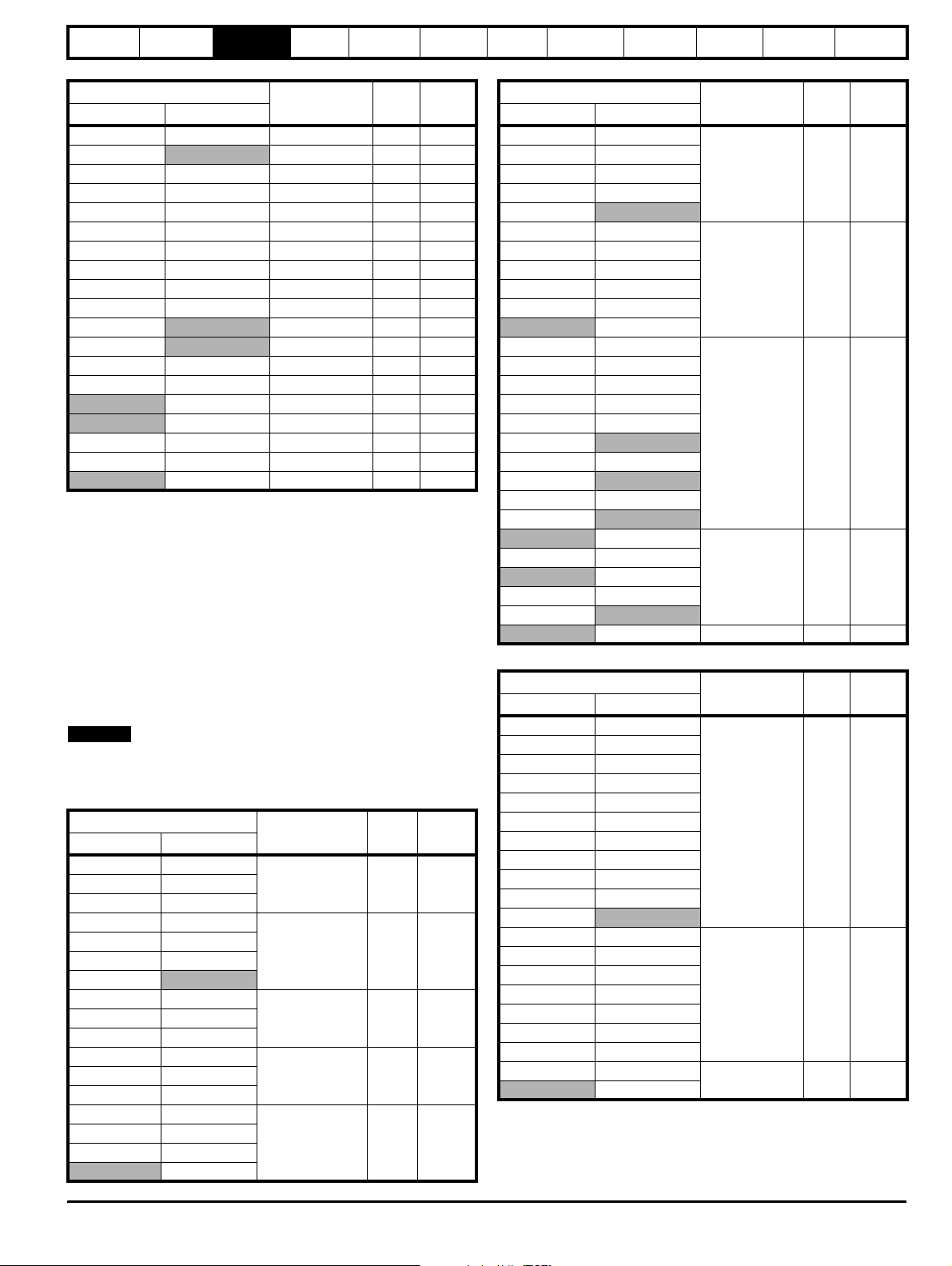
The inductors are standard three phase inductors (rated at Unidrive SP
Regen drive rated current). They carry only 50/60Hz current with a
negligible amount of high frequency current. The above switching
frequency filter inductors are calculated at 4% of the regen drives rating
using the following formula. A tolerance can be applied to the calculated
value in the range of, -10% to +30%.
L switching frequency filter mH = VLL / √3 x 1 / Irated x 0.04 x 1 / (2 x pi
x f).
Where:
VLL = Supply voltage line-to-line
f = Supply frequency
Irated = Drive rated current
NOTE
This calculation also gives the correct inductance value for a 480V, 60Hz
supply.
Table 3-20 200V (200V to 240V ± 10%) SFF Capacitors
Drive
Heavy Duty Normal Duty
Part number uF Arms
SP1203 SP1203
1664-1074 7 1.7SP1204 SP1204
SP2201 SP2201
SP2202 SP2202
SP2203 SP2203
SP3201 SP3201
1664-2174 16.6 4.3
SP3202
SP4201 SP3202
1665-8324 32 11SP4202 SP4201
SP4203 SP4202
SP5201 SP4203
1664-2644 64 17SP5202 SP5201
SPMD1201 SP5202
SPMD1202 SPMD1201
SPMD1203 SPMD1202
SPMD1204 SPMD1203
2 x 1664-2644 2 x 64 2 x 17
SPMD1204
Getting
started
Optimisation Parameters
Technical
data
Component
sizing
Table 3-21 400V (380V to 480V ± 10%) SFF Capacitors
Drive
Heavy Duty Normal Duty
Part number uF Arms
SP1405 SP1405
SP1406 SP1406
SP2401 SP2401
1610-7804 8 4.3
SP2402 SP2402
SP2403
SP2404 SP2403
SP3401 SP2404
SP3402 SP3401
SP3403 SP3402
1665-8324 32 11
SP4401 SP3403
SP4401
SP4402 SP4402
SP4403 SP4403
SP5401 SP5401
SP5402 SP5402
SP6401 SP6401
SP6402
1665-8484 48 17
SPMA1401 SPMA1401
SPMA1402
SPMD1401 SPMD1401
SPMD1402
SP6402
SPMA1402 SPMA1402
SPMD1402
1665-8774 77 26
SPMD1403 SPMD1403
SPMD1404
SPMD1404 2 x 1665-8394 2 x 39 2 x 13
Table 3-22 575V (500V to 575V ± 10%) SFF Capacitors
Drive
Heavy Duty Normal Duty
Part number uF Arms
SP3505 SP3505
SP3506 SP3506
SP3507 SP3507
SP4601 SP4601
SP4602 SP4602
SP4603 SP4603
1666-8113 11.2 5
SP4604 SP4604
SP4605 SP4605
SP4606 SP4606
SP5601 SP5601
SP5602
SP6601 SP5602
SP6602 SP6601
SPMA1601 SP6602
SPMA1602 SPMA1601
1666-8223 22.5 10
SPMD1601 SPMA1602
SPMD1602 SPMD1601
SPMD1603 SPMD1602
SPMD1604 SPMD1603
SPMD1604
2 x 1666-8233
2 x
22.5
Diagnostics
2 x 10
Unidr ive SP Re gen Inst allatio n Guide 27
Issue Number: 2 www.controltechniques.com
Page 28
Safety
Information
Introduction
Product
information
System
design
Mechanical
installation
Electrical
installation
Getting
started
Optimisation Parameters
Technical
data
Component
sizing
Diagnostics
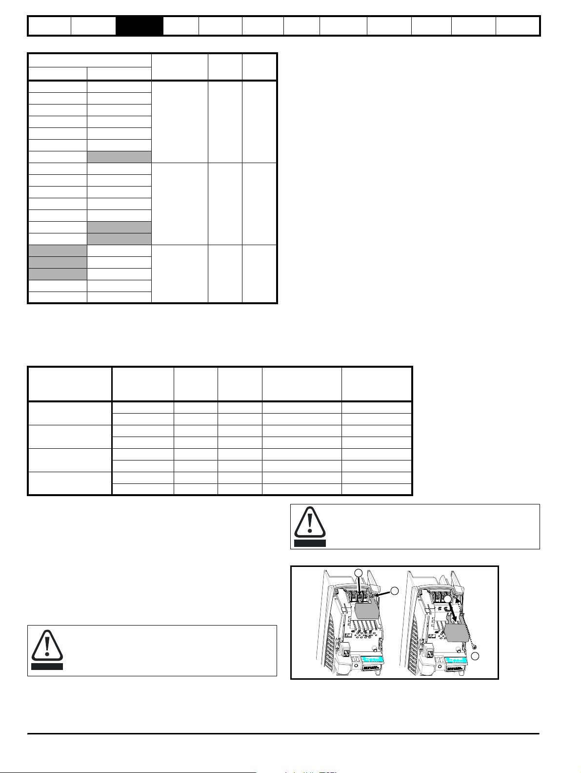
Table 3-23 690V (690V ± 10%) SFF Capacitors
Drive
Heavy Duty Normal Duty
Part number uF Arms
SP4601 SP4601
SP4602 SP4602
SP4603 SP4603
SP4604 SP4604
1668-7833 8.3 4.3
SP4605 SP4605
SP4606 SP4606
SP5601
SP5602 SP5601
SP6601 SP5602
SP6602 SP6601
SPMA1601 SPMA1601
1668-8163 16.6 8.6
SPMA1602 SPMD1601
SPMD1601
SPMD1602
SP6602
SPMA1602
SPMD1602
2 x 1668-8163 2 x 16.6 2 x 8.6
SPMD1603 SPMD1603
SPMD1604 SPMD1604
3.10.3 Varistors
AC line voltage transients can typically be caused by the switching of large items of plant or by lightning strikes on another part of the supply system.
If these transients are not suppressed they can cause damage to the insulation of the regen input inductors, or to the Regen drive electronics.
The following varistors should therefore be fitted as shown in section 4.2 Power connections .
Tab le 3-24 Va ris t or d a ta
Drive rating
200V
(200V to 240V±10%)
400V
(380V to 480V±10%)
575V
(500V to 575V±10%)
690V
(690V±10%)
Varisto r
voltage rating
V
RMS
Energy
rating
J
550 620 3 Line to line 2482-3291
680 760 3 Line to ground 2482-3211
550 620 3 Line to line 2482-3291
680 760 3 Line to ground 2482-3211
680 760 3 Line to line 2482-3211
1000 1200 3 Line to ground 2482-3218
385 550 6 2 in series line to line 2482-3262
1000 1200 3 Line to ground 2482-3218
Quantity
per
system
Configuration CT part number
3.10.4 EMC filters
In order to provide customers with a degree of flexibility, external EMC
filters have been sourced from two manufacturers, Schaffner and Epcos,
as detailed in both the Unidrive SP, and SPM User Guides.
For currents exceeding 300A up to 2500A, suitable filters are also
available from both Epcos and Schaffner as detailed.
• Epcos B84143-B250-5xx (range up to 2500A)
• Schaffner FN3359-300-99 (range up to 2400A)
These filters may not give strict conformity with EN6000-6-4 but in
conjunction with EMC installation guidelines they will reduce emissions
to sufficiently low levels to minimise the risk of disturbance.
When a EMC filter is used, the switching frequency filter
detailed must also be used. Failure to observe this may result
in the EMC filter becoming ineffective and being damaged.
CAUTION
Refer to section 6.4 EMC (Electromagnetic compatibility) on
page 77.
CAUTION
Figure 3-12 Removal of internal EMC filter (size 1 to 3)
Loosen / remove screws as shown (1) and (2).
Remove filter (3), and ensure the screws are replaced and re-tightened (4).
The internal EMC filter must be removed from the drive.
1
2
3
4
28 Unidrive SP Regen Installation Guide
www.controltechniques.com Issue Number: 2
Page 29
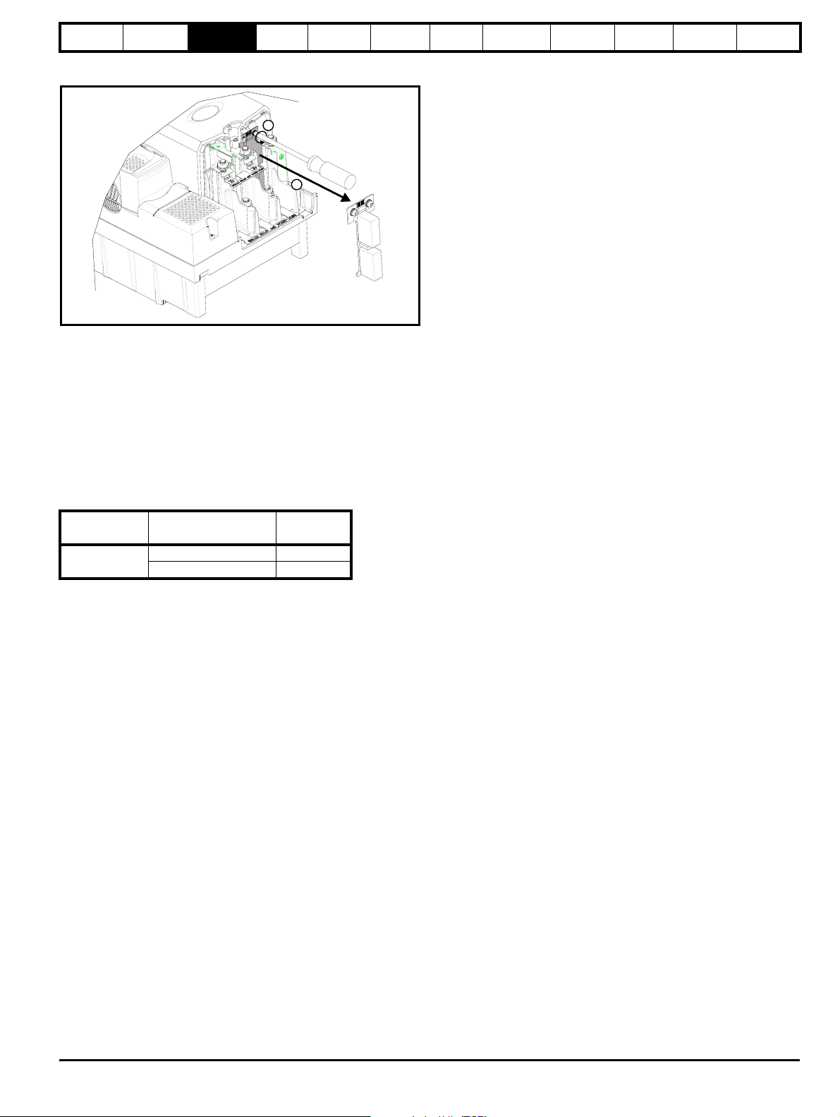
Safety
Information
Introduction
Product
information
System
design
Mechanical
installation
Electrical
installation
Figure 3-13 Removal of internal EMC filter (size 4 to 6 and the
SPMA/SPMD)
1
2
Loosen screws (1). Remove EMC filter in the direction shown (2).
3.10.5 External charging resistor
The following external charging resistors are available from Control
Techniques and can be used with a regen system consisting of multiple
regen, multiple motoring or single regen, multiple motoring drives. For
correct sizing of the charging resistor required, refer to section
11. 2 Resistor sizing for multiple drive systems on page 204. Also, see
section 10.4.2 Softstart resistor - type TG series on page 197 for further
technical data and thermal protection information on the following
resistors.
Table 3-25 External charging resistors
Drive
All sizes
External charging
resistor part no.
1270-3157 150
1270-2483 48
Ω
Getting
started
Optimisation Parameters
Technical
data
Component
sizing
Diagnostics
Unidr ive SP Re gen Inst allatio n Guide 29
Issue Number: 2 www.controltechniques.com
Page 30
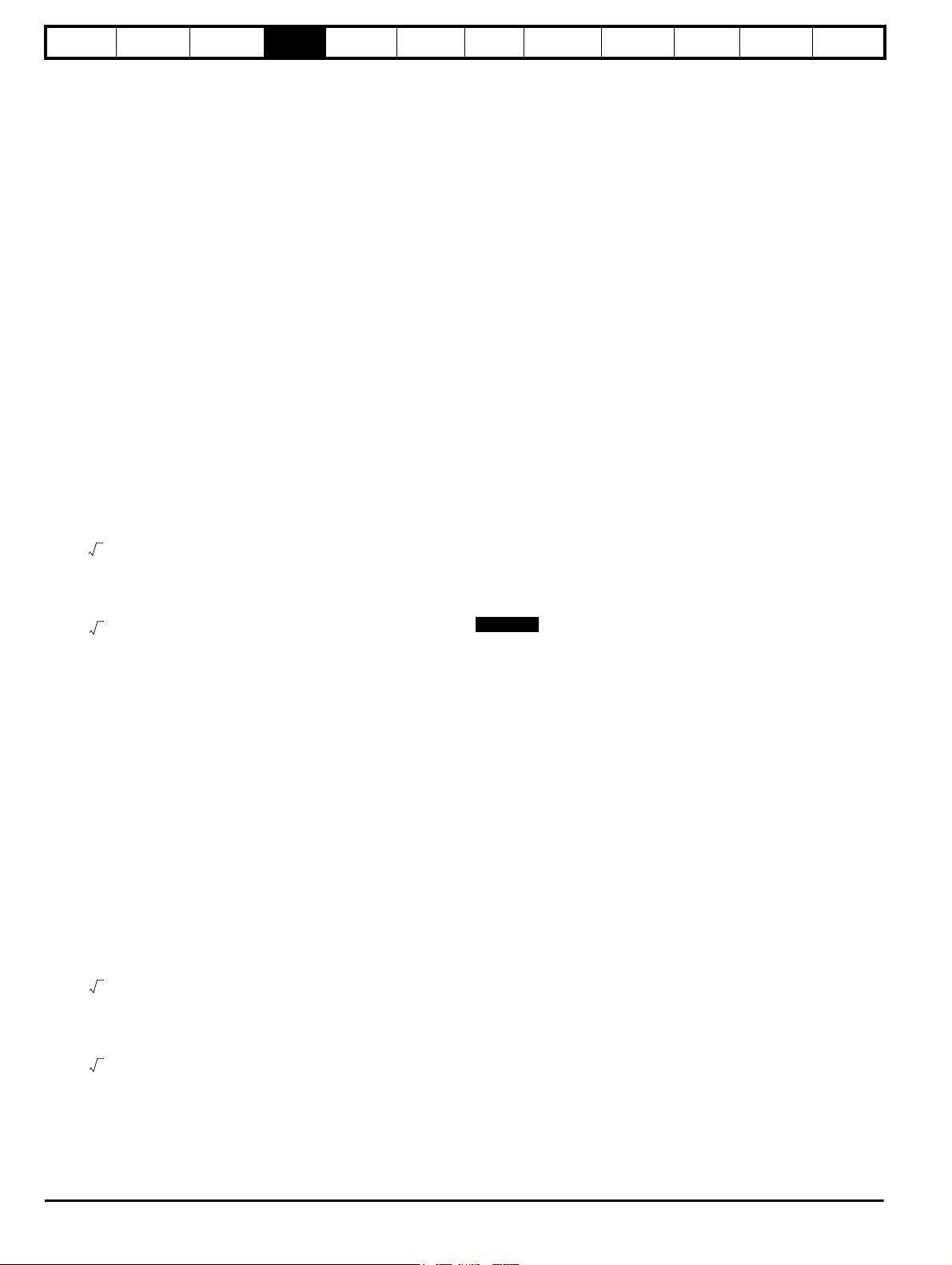
Safety
Information
Introduction
Product
information
System
design
Mechanical
installation
Electrical
installation
4 System design
4.1 Introduction
The sizing of a regen system must take into account the following
factors:
1. Line voltage variation
2. Motor rated current, rated voltage and power factor
3. Maximum required power and overload requirements
4. Heavy Duty / Normal Duty Regen drive ratings
In general, when designing a regen system, equal Regen and motoring
drive rated currents will work correctly. However, care must be taken to
ensure that under worst case supply conditions the Regen drive is able
to supply / absorb all the required power including total system losses.
If the Regen drive is unable to supply the full power required by the
motoring drive(s), the DC bus voltage will drop, and in severe cases may
lose synchronisation with the AC supply and trip. If the Regen drive is
unable to regenerate the full power from the motoring drive(s) into the
DC bus, then the Regen drive and motoring drive(s) will trip on overvoltage.
4.1.1 Single Regen, single motoring drive
The following calculations can be carried out for either a single Regen
drive, motoring drive system or single Regen drive, multiple motoring
drive system.
Example
In the case of a 23A (Normal Duty), SP2403 operating in regen mode
from a 400V supply, and a SP2403 driving a 400V rated, 0.85 pf motor:
The rated power of the Regen drive is:
3 Rated current× Supply voltage×
= 1.73 x 23 x 400
= 15.9kW
The motoring drive can supply power:
3 Rated current× Motor voltage Power factor××
= 1.73 x 23 x 400 x 0.85
= 13.5kW
Drive losses
2 x Unidrive SP 2403 = 626W
When the motoring drive is supplying rated current to the motor, the
Regen drive needs to provide 13.5kW, plus drive losses = 14.126kW.
The Regen drive can supply 15.9kW at rated current, which is ample, in
this case.
Conversely, in some cases, a Regen drive of the same rating as the
motoring drive, may not be able to supply enough power, as the
following example shows:
Example
In the case of a 96A (Heavy Duty), SP4403 operating in regen mode,
and a SP4403 driving a 75kW, 400V, 0.95pf motor:
If the motoring drive is supplying 175% maximum current, and the
Regen drive has its 380V supply at the lower limits of -10% (342Vac),
then, with a regen current limit of 150%:
Getting
started
Optimisation Parameters
Technical
data
Component
sizing
Diagnostics
requirement to 112.352kW. However, this Regen drive is only capable of
supplying approximately 85.1kW and therefore a drive of a larger rating
is required.
4.1.2 Multiple motoring drives
In multi-drive configurations, the Regen drive must be of a sufficient size
to supply the net peak power demanded by the combined load of all
motoring drives plus the combined losses, including its own losses.
Due to the effects of increased DC bus capacitance, there is a limit to the
number of motoring drives that can be supplied from a Regen drive. This
is true irrespective of the balance of power between the motoring drives
and the Regen drive.
The previous calculations can be used for the sizing of multiple motoring
drives also.
4.2 Power connections
The following section covers the power connections required for
Unidrive SP regen systems.
• For single Regen, single motoring systems, AC supply connections
are made to L1, L2 and L3 drive terminals and the drive’s internal
soft start circuit is used for power-up.
• The single Regen, multiple motoring and multiple regen, multiple
motoring systems require an external charging circuit due to the
extra capacitance from the additional drives. No AC connections are
made to the Regen drive’s L1, L2 and L3 terminals. The external
charging circuit can consist of either the SPMC solution or an
external charging resistor as shown in the following.
• For the regen brake resistor replacement system, the motoring
drive’s internal soft start is used for power-up with no AC
connections to L1, L2, L3 on the Regen drive.
For control circuit connections refer to section 6.6 Control
connections on page 83.
NOTE
If the regen system is not a standard configuration or changes are
required to the following systems and set ups, contact the supplier of the
drive.
The Regen drive maximum available power is:
3 150% Rated current×× Supply voltage×
= 1.73 x 1.5 x 96 x 342
= 85.1kW
The motoring drives maximum. power is:
3 175% Rated current× Motor voltage×× Power factor×
= 1.73 x 1.75 x 96 x 400 x 0.95
= 110.4kW
Drive losses
2 x Unidrive SP 4403 = 1.952kW
The Regen drive is also required to supply the Regen and motoring drive
losses in this example 1.952kW which brings the total power
30 Unidrive SP Regen Installation Guide
www.controltechniques.com Issue Number: 2
Page 31
Safety
Information
Introduction
Product
information
System
design
Mechanical
installation
Electrical
installation
Getting
started
Optimisation Parameters
Technical
data
Component
sizing
Diagnostics
Unidr ive SP Re gen Inst allatio n Guide 31
Issue Number: 2 www.controltechniques.com
Page 32

Safety
A
A
A
Information
Introduction
Product
information
System
design
Mechanical
installation
Electrical
installation
Getting
started
4.2.1 Single Regen, single / multiple motoring system
Figure 4-1 Power connections: Single Regen, single / multiple motoring system
L1
L2
L3
RFI
F1 F2 F3
K1
K2
VDR4
Aux.2a
VDR1
VDR2
VDR5
VDR6
Charging branch circuit
Aux.2b
C1
VDR3
Aux.3
Supply
ground
K3
L1 L2 L3 PE
AC Supply
Power-up
Connections
-DC +DC
Motoring
drive DC
Connections
Regen drive
AC Supply
Connections
UVW
1
Vsupply
Aux.2b
K3
21
0V common
2 3 4 5 6 7 8 9 10 11 41 42
Drive healthy
S6
Reset input
Technical
data
Contactor
Optimisation Parameters
Note: Surge suppressors to be fiited to contactor coils.
ux.3
ux.2a
22 23 24 25 26 27 28 29 30 31
V
+24 output
Contactor clo sed
Enable motor drive
thermistor
Regen inductor
Component
sizing
S1
ux.1
V
0common
Drive enable
control
-DC
+DC
Rly.1
(optional)
Diagnostics
T.2 4
T.3 0
L1
OPD1
Table 4-1 Key to Figure 4-1
Key Description
L1, L2, L3 Three phase supply
F1, F2, F3 Main regen system supply fuses
VDR1, VDR2, VDR3 Varistor network line-to-line
VDR4, VDR5, VDR6 Varistor network line-to-ground
RFI Optional RFI Filter
C1 Switching frequency filter capacitor
L1 Switching frequency filter inductor
L2 Regen inductor
K1 Main supply switch or contactor
K2 Regen drive main contactor
K3 Charging contactor
OPD1 Overload protection device for C1
Aux.3 K3 NC auxiliary contact
Aux.2a K2 NO auxiliary contact
Aux.2b K2 NC auxiliary contact
Aux.1 OPD1 NO auxiliary contact
Rly.1
Mt.1 Motor thermistor
Tc.1 Regen inductor thermistor
Optional isolation for enable between Regen and motoring drive
Aux.1
K2
Vsupply
L2
Tc. 1
Table 4-1 Key to Figure 4-1
Key Description
Vsupply System control supply
+DC, -DC Motoring drive power connection to Regen drive
S1 Regen drive enable
S2 Motoring drive enable
S3 Motoring drive reset
S4 Motoring drive run forward
S5 Motoring drive run reverse
S6 Regen drive reset input (Pr 8.24 = Pr 10.33)
Figure 4-1 shows both the power and control connections for the standard
regen solution this being a single regen and single motoring drive system.
For this solution the Vac supply is temporarily connected to the Regen
drive’s L1, L2, L3 inputs for initial power-up only, removing the need for
an external charging circuit. The main AC supply to L1, L2, L3 on the
Regen drive (K3) is interlocked with the Regen drive’s enable preventing
operation when the charging circuit is still connected.
NOTE
The regen inductor duty is very arduous and therefore selection is critical
as a result only Regen inductors specified in this guide should be used.
32 Unidrive SP Regen Installation Guide
www.controltechniques.com Issue Number: 2
Page 33
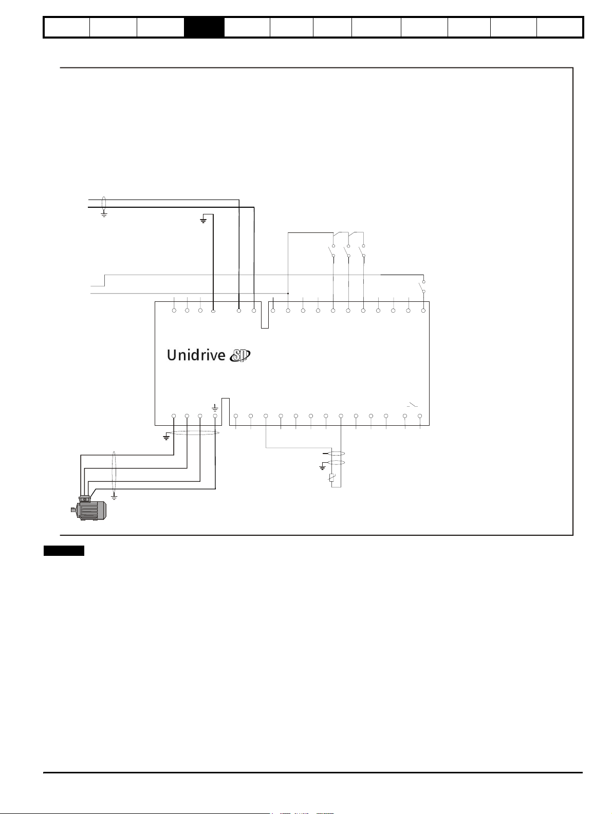
Safety
Information
-DC
+DC
Introduction
Product
information
System
design
Mechanical
installation
Electrical
installation
Getting
started
Optimisation Parameters
Technical
data
Component
sizing
Diagnostics
T.2 4
T.3 0
L1 L2 L3 PE
AC Supply
NOT USED
-DC +DC
Motoring
drive DC
Connections
21
22 23 24 25 26 27 28 29 30 31
+24V output
Motoring drive
Motor
Connections
NOTE
UVW
U
V
W
PE
1
VDR4, VDR5 and VDR6 when operating with a 690Vac supply should
consist of two varistors each in series as detailed in Table 3-24 on
page 28.
0V common
2 3 4 5 6 7 8 9 10 11 41 42
Mt.1
S3 S4
Drive reset
S5
S2
V
Run forwar d
Run revers e
Motor thermistor
0common
Drive enable
Drive healthy
Unidr ive SP Re gen Inst allatio n Guide 33
Issue Number: 2 www.controltechniques.com
Page 34

Safety
Information
Introduction
Product
information
System
design
Mechanical
installation
Electrical
installation
Getting
started
Optimisation Parameters
4.2.2 Single Regen, multiple motoring system using a Unidrive SPMC
Figure 4-2 Power connections: Single Regen, multiple motoring system
-DC
Aux.2c
85
84
0V common
F13
F14
F11
+24Vdc external supply
F12
L1
L2
L3
F1 F2 F3
K1
VDR4
Unidrive
SPMC
L1L2L3
VDR3
VDR2
VDR6
VDR5
+DC
Aux.2a
Technical
data
S6
K3
Component
sizing
Vsupply
Aux.2b
Diagnostics
-DC
+DC
S1
T.2 4
T.3 0
control
K2
Rly.1
optional
Drive enable
Vsupply
RFI
Charging
branch
circuit
K3
L1
OPD1
C1
Aux.1
L2
Aux.3
K2
Connections
NOT USED
L1 L2 L3 PE
AC Supply
Regen drive
AC Supply
Connections
UVW
2a 2b 2c
Aux
-DC +DC
Motoring
drive DC
Connections
1
21
22 23 24 25 26 27 28 29 30 31
V
+24 output
Enable motor drive
0V common
2 3 4 5 6 7 8 9 10 11 41 42
Contactor close d
thermistor
Regen inductor
Tc. 1
Reset input
Drive healthy
V
0common
Contactor
Table 4-2 Key to Figure 4-3 Figure 4-2 shows both the power and control connections for the
Key Description
L1, L2, L3 Three phase supply
F1, F2, F3 Main regen system supply fuses
VDR1, VDR2, VDR3 Varistor network line-to-line
VDR4, VDR5, VDR6 Varistor network line-to-ground
F7, F8, F9, F10
F11, F12
F13, F14
RFI Optional RFI filter
C1 Switching frequency filter capacitor
L1 Switching frequency filter inductor
L2 Regen inductor
K1 Main supply contactor
K2 Regen drive main contactor
K3 Charging contactor
OPD1 Overload protection device for C1
Aux.1 OPD NO auxiliary contact
Aux.2a K2 NO auxiliary contact
Aux.2b K2 NC auxiliary contact
Aux.2c NC auxiliary for SPMC (optional)
Aux.3 K3 NC auxiliary contact
Rly.1
Mt.1 Motor thermistor 1
Mt.2 Motor thermistor 2
Tc.1 Regen inductor thermistor
+DC, -DC Motoring drive power connection to Regen drive
S1 Regen drive enable
S2 Motoring drive e nable
S3 Motoring drive reset
S4 Motoring drive run forward
S5 Motoring drive run reverse
S6 Regen drive reset input (Pr 8.24 = Pr 10.33)
Vsupply System control supply
DC bus fusing to motoring drive
DC bus fusing to Regen drive
SPMC DC fuse protection
Optional isolation for enable between Regen and motoring drive(s)
multiple motoring regen solution. For the multiple motoring system an
external charging circuit is required due to the additional capacitance
from the multiple motoring drives. The external charging circuit is
interlocked with the Regen drive enable to prevent operation with this
circuit still connected.
In this example, the external charging circuit consists of a Unidrive SPMC
module. Refer to section 3.5 Unidrive SPMC half controlled thyristor
rectifier on page 19 for further details of the Unidrive SPMC.
NOTE
For the multiple motoring drive solution, the Regen drive and associated
Unidrive SPMC must be sized to the total power requirements of all
motoring drives.
NOTE
The regen inductor duty is very arduous and therefore selection is critical.
As a result only regen inductors specified in this guide should be used.
NOTE
Fusing F4, F5, F6 are only required where fusing F1, F2, F3 exceed
these. For example in a multiple regen drive system, where F1, F2, F3
equal total system current rating.
NOTE
The SPMC uses the regen inductor as line reactors. The SPMC may be
powered from the incoming supply using a standard line reactor if
required.
34 Unidrive SP Regen Installation Guide
www.controltechniques.com Issue Number: 2
Page 35
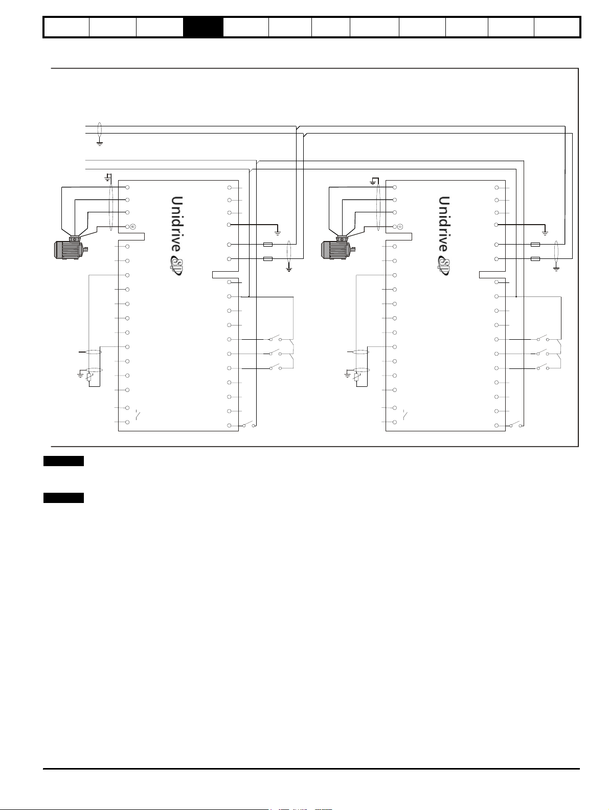
Safety
Information
-DC
+DC
T.2 4
T.3 0
Introduction
information
UVW
Connections
Motor
Product
Motoring drive
System
design
Connections
NOT USED
L1 L2 L3 PE
AC Supply
Mechanical
installation
Electrical
installation
Getting
started
Optimisation Parameters
UVW
Connections
Motor
Motoring drive
Technical
data
NOT USED
Connections
AC Supply
Component
sizing
L1 L2 L3 PE
Diagnostics
V
U
W
PE
Mt.1
NOTE
DC bus fusing is required for all motoring drives in a single Regen,
1
2 3 4 5 6 7 8 9 10 11 41 42
0V common
Motor thermistor
Drive healthy
Connections
drive DC
Drive reset
Run forward
Run reverse
0V common
Drive enable
-DC +DC
Motoring
21
22 23 24 25 26 27 28 29 30 31
F7
F8
S3 S4
S5
S2
multiple drive system in both the +DC and -DC.
NOTE
VDR4, VDR5 and VDR6 when operating with a 690Vac supply should
consist of two varistors each in series as detailed in Table 3-24 on
page 28.
See Chapter 10 Technical data on page 183 for fuse rating information.
Unidrive SPMC
For a regen system, the SPMC can be used to charge the common DC
bus when the power is first applied, however this will once the regen
system is powered up no longer be required.
The Unidrive SPMC must be supplied with 24Vdc to feed both the fans
and control circuits. This 24Vdc can also be used as a means of starting
and stopping the SPMC rectifier as the SPMC will only fire its thyristors
when the 24Vdc is present.
Fitting a 5A relay interlocked (or a normally closed auxiliary contact) to
the Regen drives main contactor to switch the 24V supply will allow the
SPMC to charge the common DC bus then be disabled (optional).
The total amount of capacitance on the common DC bus that the SPMC
can drive is limited due to the inrush current (produced during power up
and during brownouts).
See the following Table for the capacitance limit.
Unidrive SP drive DC bus capacitance levels are available in Table 111 on page 203.
V
U
Mt.2
W
PE
1
2 3 4 5 6 7 8 9 10 11 41 42
0V common
Motor thermistor
Drive healthy
Connections
drive DC
+24V output+24V output
Drive reset
Run forward
Run reverse
0V common
Drive enable
-DC +DC
Motoring
21
22 23 24 25 26 27 28 29 30 31
F9
F10
S3 S4
S5
S2
Unidr ive SP Re gen Inst allatio n Guide 35
Issue Number: 2 www.controltechniques.com
Page 36
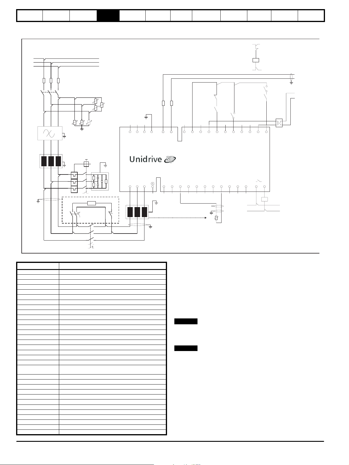
Safety
Information
Introduction
Product
information
System
design
Mechanical
installation
Electrical
installation
Getting
started
Optimisation Parameters
4.2.3 Single Regen, multiple motoring system using an external charging resistor
Figure 4-3 Power connections: Single Regen, multiple motoring system
Technical
data
Vsupply
Aux.2b
Component
sizing
Diagnostics
L1
L2
L3
RFI
L1
F1 F2 F3
K1
VDR4
OPD1
Charging branch circuit
K3
VDR1
VDR2
VDR6
VDR5
Aux.1
Rs.1
Aux.3 OPD2
K2
VDR3
K3
-DC
+DC
L1 L2 L3 PE
AC Supply
Connections
NOT USED
F8
-DC +DC
Motoring
drive DC
Connections
S1
Aux.3
F9
Aux.2a
S6
21
22 23 24 25 26 27 28 29 30 31
V
+24 output
a
En ble motor drive
Reset input
Drive healthy
Contactor closed
V
0 common
Aux.1
Drive enable
Rly.1
optional
T.24
T.30
Regen drive
AC Supply
C1
Connections
UVW
L2
1
0V common
2 3 4 5 6 7 8 9 10 11 41 42
Tc.1
thermistor
Regen inductor
control
Contactor
K2
Vsupply
Aux.2a
Aux.2b
Table 4-3 Key to Figure 4-3 Figure 4-3 shows both the power and control connections for the
Key Description
L1, L2, L3 Three phase supply
F1, F2, F3 Main regen system supply fuses
VDR1, VDR2, VDR3 Varistor network line-to-line
VDR4, VDR5, VDR6 Varistor network line-to-ground
F4, F5, F6, F7
F8, F9
RFI Optional RFI filter
C1 Switching frequency filter capacitor
L1 Switching frequency filter inductor
L2 Regen inductor
K1 Main supply contactor
K2 Regen drive main contactor
K3 Charging contactor
OPD1 Overload protection device for C1
OPD2 Overload protection device for Rs.1
Aux.1 OPD1 NO auxiliary contact
Aux.2a K2 NO auxiliary contact
Aux.2b K2 NC auxiliary contact
Aux.3 K3 NC auxiliary contact
Rly.1
Mt.1 Motor thermistor 1
Mt.2 Motor thermistor 2
Tc.1 Regen inductor thermistor
Rs.1 Charging resistor
+DC, -DC Motoring drive power connection to Regen drive
S1 Regen drive enable
S2 Motoring drive enable
S3 Motoring drive reset
S4 Motoring drive run forward
S5 Motoring drive run reverse
S6 Regen drive reset input (Pr 8.24 = Pr 10.33)
Vsupply System control suply
DC bus fusing to motoring drive
DC Bus fusing to regen drive
Optional isolation for enable between Regen and motoring
drive(s)
multiple motoring regen solution. For this multiple motoring system
solution an external charging circuit is required due to the additional
capacitance from the multiple motoring drives. The external charging
circuit is interlocked with the Regen drive enable to prevent operation
with this circuit still connected.
For sizing of the external charging circuit required for the multiple
motoring drive system, refer to Chapter 11 Component sizing on
page 203. For details on charging resistors and protection refer to
section 10.4.2 Softstart resistor - type TG series on page 197.
NOTE
For the multiple motoring drive solution, the Regen drive and associated
external components must be sized to the total power requirements of all
motoring drives.
NOTE
The regen inductor duty is very arduous and therefore selection is
critical. As a result only regen inductors specified in this guide should be
used.
36 Unidrive SP Regen Installation Guide
www.controltechniques.com Issue Number: 2
Page 37
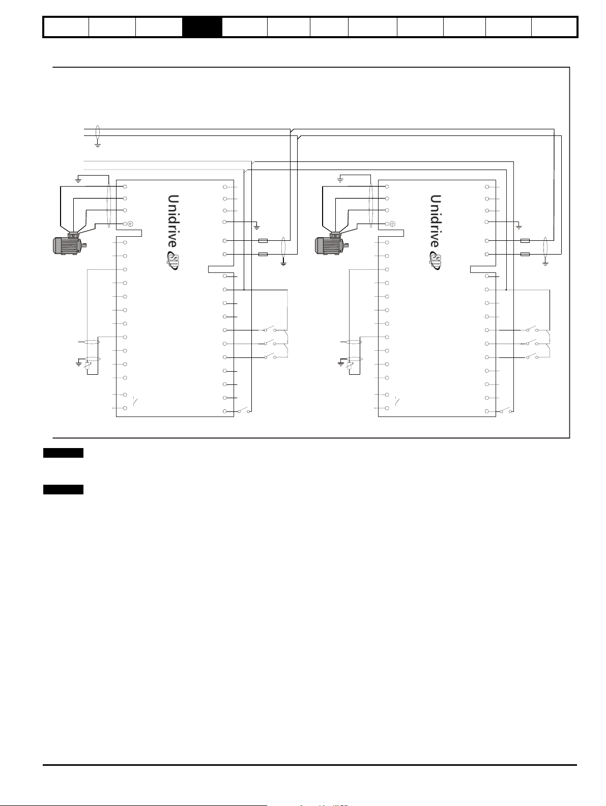
Safety
Information
-DC
+DC
T.2 4
T.3 0
Introduction
information
UVW
Connections
Product
Motor
System
design
Motoring drive
NOT USED
Connections
L1 L2 L3 PE
AC Supply
Mechanical
installation
Electrical
installation
Getting
started
Optimisation Parameters
UVW
Connections
Motor
Motoring drive
Technical
data
Connections
NOT USED
AC Supply
Component
L1 L2 L3 PE
sizing
Diagnostics
V
U
W
PE
Mt.1
NOTE
DC bus fusing is required for all motoring drives in a single Regen,
1
2 3 4 5 6 7 8 9 10 11 41 42
0V common
Motor thermistor
Drive healthy
Connections
drive DC
+24V output
Drive reset
Run forward
Run reverse
0V common
Drive enable
-DC +DC
Motoring
21
22 23 24 25 2 6 27 28 29 30 31
F4
F5
S3 S4
S5
S2
multiple motoring drive system in both the +DC and -DC.
NOTE
VDR4, VDR5 and VDR6 when operating with a 690Vac supply should
consist of two varistors each in series as detailed in Table 3-24 on
page 28.
See Chapter 10 Technical data on page 183 for fuse rating information.
V
U
Mt.2
W
PE
1
2 3 4 5 6 7 8 9 10 11 41 42
0V common
Motor thermistor
Drive healthy
Connections
drive DC
+24V output
Drive reset
Run forward
Run reverse
0V common
Drive enable
-DC +DC
Motoring
21
22 23 24 25 2 6 27 28 29 30 31
F6
F7
S3 S4
S5
S2
Unidr ive SP Re gen Inst allatio n Guide 37
Issue Number: 2 www.controltechniques.com
Page 38
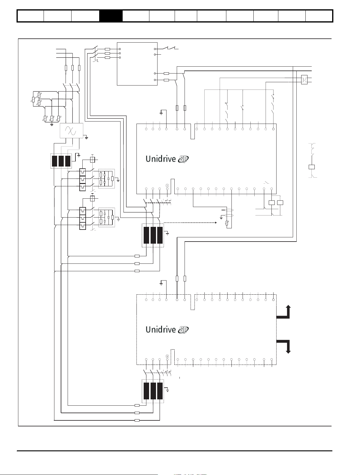
Safety
Information
Introduction
Product
information
System
design
Mechanical
installation
Electrical
installation
Getting
started
4.2.4 Multiple Regen, multiple motoring using Unidrive SPMC
Figure 4-4 Power connections: Multiple Regen, multiple motoring system
VDR3
VDR1
VDR2
VDR6
K3
L1
L2
L3
F1 F2 F3
K1
VDR4
VDR5
L1 L2 L3
RFI
L1
Aux.3
OPD1
F10
F11
F12
L1
L2
L3
Unidrive
SPMC
85
84
+DC
-DC
L1 L2 L3 PE
AC Supply
Connections not used
Regen drive 1 master
AC Supply
Connections
UVW
K2
OPD2
Aux.1
C1
Aux.2c
0V common
F13
F14
2a 2b 2c Aux
Aux.4c
+24Vdc external supply
F16
F15
-DC +DC
Motoring
drive DC
Connections
1
2 3 4 5 6 7 8 9 10 11 41 42
Optimisation Parameters
Aux.3
S6
Aux.2a
Aux.4a
21
22 23 24 25 26 27 28 29 30 31
0V common
V
+24 output
Enable motor drive
+10V user output
Contactor closed
Regen inductor
Drive healthy
thermistor
Reset input
Vsupply
Technical
data
V
0 common
control
Contactor
K2
Component
S1
Aux.2
Aux.1
Drive enable
K4
sizing
Rly.1
optional
Diagnostics
-DC
+DC
T.24
T.30
Vsupply
Aux.2b
Aux.4b
K3
Aux.2
Tc.1
C2
L2
F4
F5
F6
L1 L2 L3 PE
AC Supply
Connections not used
Regen drive 2 Slave
AC Supply
Connections
UVW
K4
L3
4a 4b 4c Aux
4a 4b 4c Aux
F18
F17
-DC +DC
Motoring
drive DC
Connections
1
21
22 23 24 25 26 27 28 29 30 31
2 3 4 5 6 7 8 9 10 11 41 42
Control cable
to regen master
Control cable
to additional
regen slave
F7
F8
F9
38 Unidrive SP Regen Installation Guide
www.controltechniques.com Issue Number: 2
Page 39
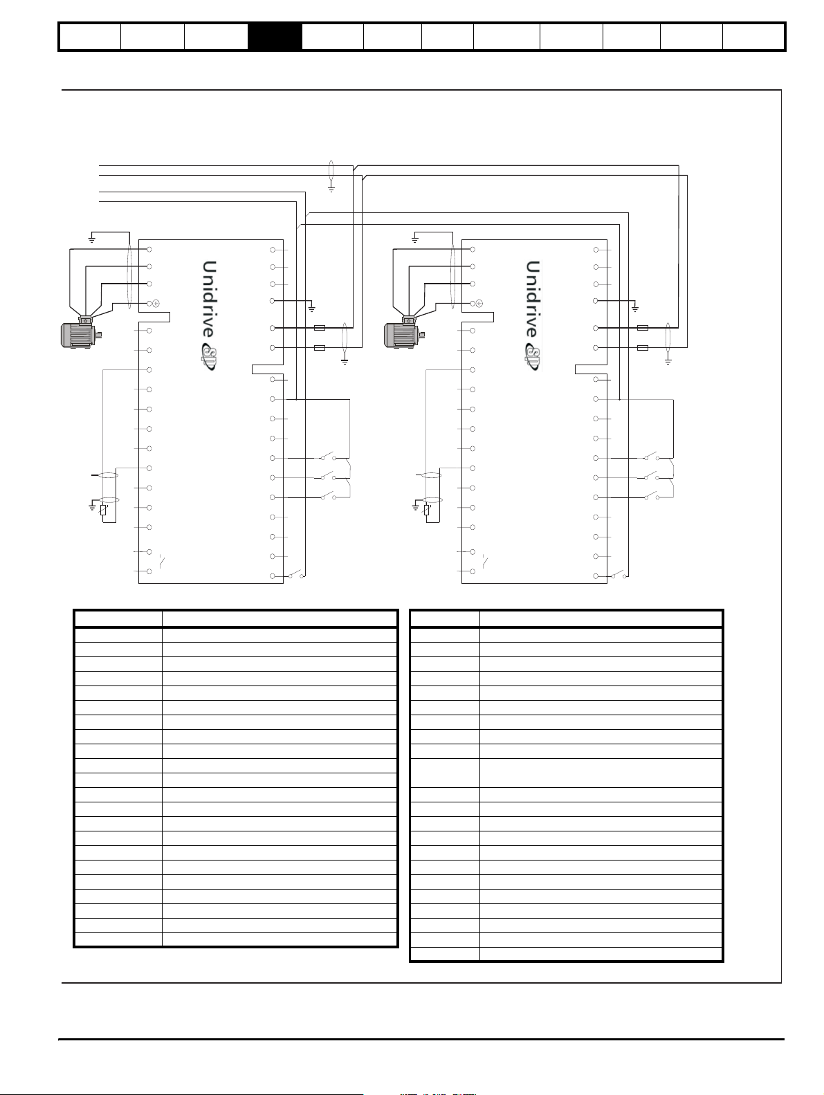
Safety
Information
-DC
+DC
T.24
T.30
Introduction
Product
information
System
design
Mechanical
installation
Electrical
installation
Getting
started
Optimisation Parameters
Technical
data
Component
sizing
Diagnostics
Connections
NOT USED
Connections
drive DC
+24V output
Drive reset
Run forward
Run reverse
0V common
Drive enable
AC Supply
Motoring
L1 L2 L3 PE
-DC +DC
21
22 23 24 25 26 27 28 29 30 31
UVW
Connections
Motor
Motoring drive
UVW
Mt.2
PE
1
2 3 4 5 6 7 8 9 10 11 41 42
0V common
Motor thermistor
Drive healthy
F19
F20
S3 S4
S5
S2
Connections
NOT USED
Connections
drive DC
+24V output
Drive reset
Run forward
Run reverse
0V common
Drive enable
AC Supply
Motoring
UVW
Mt.1
UVW
Connections
Motor
Motoring drive
PE
1
2 3 4 5 6 7 8 9 10 11 41 42
0V common
Motor thermistor
Drive healthy
Table 4-4 Key to Figure 4-4
Key Description Key Description
L1, L2, L3 Three phase supply Aux.1 OPD1 NO auxiliary contact
F1, F2, F3 Main regen system supply AC fuses Aux.2 OPD2 NO auxiliary contact
F4, F5, F6 Regen drive 1 AC fuses Aux.2a K2 NO auxiliary contact regen 1
F7, F8, F9 Regen drive 2 AC fuses Aux.2b K2 NC auxiliary contact regen 1
F10, F11, F12 SPMC AC fusing Aux.2c K2 NC auxiliary contact regen 1
F13, F14 DC Bus fusing to SPMC Aux.3 K3 NC auxiliary contact
F15, F16, F17, F18 DC Bus fusing to regen drives Aux.4a K4 NO auxiliary contact regen 2
F19, F20, F21, F22 DC Bus fusing to motoring drive Aux.4b K4 NC auxiliary contact regen 2
VDR1, 2, 3 Varistor network line-to-line Aux.4c K4 NC auxiliary contact regen 2
VDR4, 5, 6 Varistor network line-to-ground
RFI Optional RFI filter
Rly.1
Optional isolation for enable between Regen and
motoring drive(s)
L1 Switching frequency filter inductor Mt.1 Motor thermistor 1
L2 Regen inductor (regen 1) Mt.2 Motor thermistor 2
L3 Regen inductor (regen 2) Tc.1 Regen inductor thermistor
C1 Switching frequency filter capacitor (regen 1) Tc.2 Regen inductor thermistor
C2 Switching frequency filter capacitor (regen 2) +DC, -DC Motoring drive power connection to Regen drive
K1 Main supply contactor S1 Regen drive enable
K2 Regen drive 1 main contactor S2 Motoring drive enable
K3 Charging contactor S3 Motoring drive reset
K4 Regen drive 2 main contactor S4 Motoring drive run forward
OPD1 Overload protection device for C1 S5 Motoring drive run reverse
OPD2 Overload protection device for C2 S6 Regen drive reset (user programmed)
Vsupply System control supply
L1 L2 L3 PE
-DC +DC
21
22 23 24 25 26 27 28 29 30 31
F21
F22
S3 S4
S5
S2
Unidr ive SP Re gen Inst allatio n Guide 39
Issue Number: 2 www.controltechniques.com
Page 40
Safety
Information
NOTE
For the multiple motoring drive solution, the Regen drive and associated
Introduction
Product
information
System
design
Mechanical
installation
Electrical
installation
external components must be sized to the total power requirements of all
motoring drives.
NOTE
The regen inductor duty is very arduous and therefore selection is
critical. As a result only regen inductors specified in this guide should be
used.
NOTE
VDR4, VDR5 and VDR6 when operating with a 690Vac supply should
consist of two varistors each in series as detailed in Table 3-24 on
page 28.
4.2.5 Regen and motoring drive ratings
NOTE
The Regen drive’s current limits are detailed in section 3.3 Ratings on
page 13.
In general the Regen drive must be rated at a power greater than, or
equal to, the maximum braking power.
Example:
• Two 30kW motoring drives are each driving 30kW motors. The load
If each motor supplies between 20 and 30kW motoring, and the braking
power varies from 0 to 30kW, the maximum total braking power is 30 20 = 10kW, which is what the Regen drive should be rated for.
In drive configurations where the motoring drive power rating is several
times the expected braking power, it is necessary to consider the peak
braking power returned from the load.
Example:
• The motoring drive is a 75kW Unidrive SP. Motoring power is 75kW.
From these figures, it may appear that a 22kW Regen drive will provide
sufficient braking power. However, dynamically the peak braking power
could be much greater. If the 75kW drive current limits are set at 150%
for motoring and braking (default settings), the peak brake power could
be:
This is much greater than the 22kW Regen drive is able to return to the
supply, hence a larger drive is required.
NOTE
If the Regen drive is not rated for the required braking power, then the
drives will trip on DC bus over-voltage.
N
is such that only one drive is braking at a time.
Steady state braking power is 20kW.
√3 × 156A × 400V × 150% = 162kW
N
4.3 Non standard applications
4.3.1 Omitting the switching frequency filter
If the supply to the Regen drive is shared with other equipment, then it is
generally recommended that a switching frequency filter should be
incorporated in order to avoid the risk of interference or damage to the
other equipment. However some saving in cost and space is possible by
omitting the filter if the supply impedance is very low compared to that of
the drive, i.e. if the drive current rating is much less than that of the
supply where it is shared with other equipment.
4.3.2 Supply assessment
The following guidelines should be used when assessing whether or not
a switching frequency filter is required.
Symbols used are:
Nominal drive 100% current rating.
I
Drive
Short circuit current of supply at point of coupling with other
I
SC
equipment.
I
Rated current of supply.
Supply
Getting
started
Optimisation Parameters
Technical
data
Component
sizing
Diagnostics
The switching frequency filter may be omitted if the following relation is
true:
I
Drive
I
SC
1
<
140
If the short-circuit current is not known, then a reasonable estimate can
be made if it is assumed that the fault current of the supply is 20 times
the rated current. This is very commonly the case where the supply is
derived through a distribution transformer from a higher voltage supply
with a high fault level.
Then:
I
Drive
I
Supply
1
<
7
Note that the short-circuit current data used must be realistic, it must not
be the maximum likely value which is sometimes used when selecting
the interrupting capacity of switchgear and protection devices.
This second relation is helpful if the short-circuit current of the supply is
not known, but must be used with care. It is reliable where the Regen
drive is supplied through its own cable run from a point close to the
distribution transformer terminals. If the Regen drive shares a long cable
run with other equipment, then the effect of the cable impedance on the
fault level must be taken into account if a risk of disturbance to the other
equipment is to be avoided.
This procedure will normally be applied when assessing a non-dedicated
low-voltage supply. It may also be applied to the medium/high voltage
supply where the low-voltage supply is dedicated to the drive. In that
case the currents used must be referred to the high voltage side of the
transformer.
If the supply to the regen system has an unusually high impedance, for
example because it derives from a generator whose rating is not much
greater than that of the drive, then a more complex filter might be
required to ensure stability of the current control loops. Please contact
the supplier of the drive if it is to be used with a generator whose rating is
less than twice that of the drive.
4.4 Cable length restrictions
There are 3 significant cable lengths which must be taken into account
when designing a regen system. Refer to Figure 4-5 on page 41.
4.4.1 AC supply connection
A is the AC cable length between the regen inductor and the Regen
drives terminals.
In general, no special precautions are necessary for the AC supply
wiring in respect to the Regen drive. Ideally, the regen inductors should
be mounted close to the drive terminals.
If it is necessary to use a cable longer than 5m, a screened cable should
be used with the screen grounded.
4.4.2 DC bus connection
B is the length of the DC bus connection between the Regen and
motoring drive, the + DC bus connections between the drives should be
treated as a single two core cable and not two individual cable / bus bar
lengths.
The DC power output from the Unidrive SP which is used as the input
stage to the motoring drive(s) carries a common-mode high frequency
voltage comparable with the output voltage from a standard drive. All
precautions recommended for motor cables must also be applied to all
cables connected to this DC circuit.
40 Unidrive SP Regen Installation Guide
www.controltechniques.com Issue Number: 2
Page 41
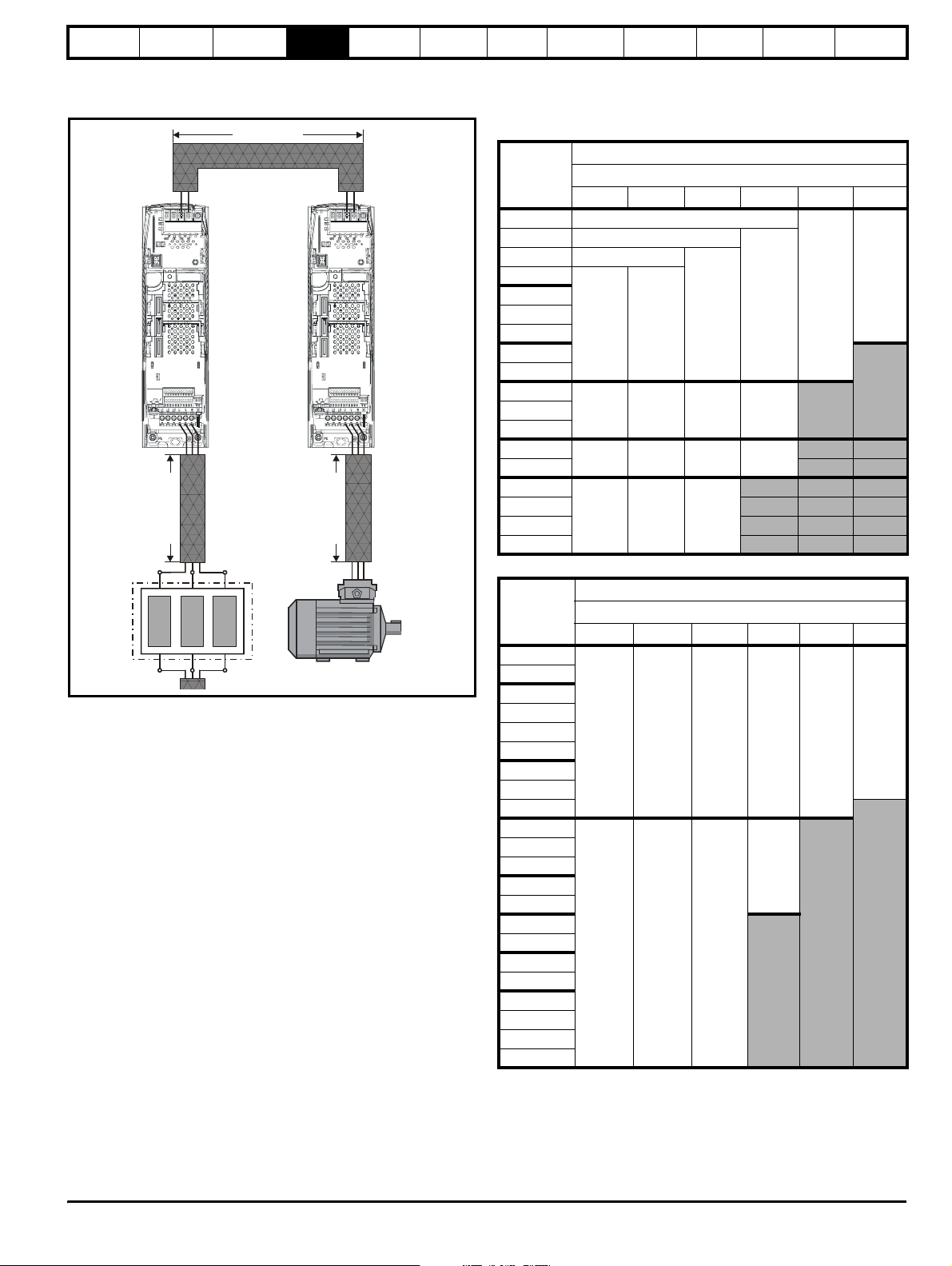
Safety
g
Information
Introduction
Product
information
System
design
Mechanical
installation
Electrical
installation
Getting
started
Optimisation Parameters
Technical
data
Component
sizing
Diagnostics
4.4.3 Motor connection
C is the AC cable length between the motoring drive and the motor.
Figure 4-5 Calculating the cable length of the regen system
Cable length B
4.4.4 Cable length
The sum total length of the DC bus and motor cables (B and C in Figure
4-5) must not exceed the values shown in the table below:
Table 4-5 200V Regen system maximum cable lengths
200V Nominal AC supply voltage
±
DC bus connections
Model
Maximum permissible cable length
3kHz 4kHz 6kHz 8kHz 12kHz 16kHz
R
e
e
n
d
r
i
v
e
M
o
t
o
r
i
n
g
d
r
i
v
e
SP1201 65m (210ft)
SP1202 100m (330ft)
SP1203 130m (425ft)
SP1204
SP2201
SP2202
SP2203
200m
(660ft)
150m
(490ft)
100m
(330ft)
75m
(245ft)
50m
(165ft)
37m
(120ft)
SP3201
SP3202
SP4201
SP4202
SP4203
SP5201
C
a
b
l
e
l
e
n
g
t
h
A
Regen inductor Motor
C
a
b
l
e
l
e
n
g
t
h
C
SP5202
SPMD1201
SPMD1202
SPMD1203
SPMD1204
Table 4-6 400V Regen system maximum cable lengths
65m
(210ft)
250m
(820ft)
250m
(820ft)
65m
(210ft)
185m
(607ft)
185m
(607ft)
65m
(210ft)
125m
(410ft)
125m
(410ft)
65m
(210ft)
90m
(295ft)
400V Nominal AC supply voltage
Model
Maximum permissible cable length
3kHz 4kHz 6kHz 8kHz 12kHz 16kHz
SP1405
SP1406
SP2401
SP2402
SP2403
SP2404
200m
(660ft)
150m
(490ft)
100m
(330ft)
75m
(245ft)
50m
(165ft)
37m
(120ft)
SP3401
SP3402
SP3403
SP4401
SP4402
SP4403
SP5401
90m
(295ft)
SP5402
SP6401
SP6402
SPMA1401
250m
(820ft)
185m
(607ft)
125m
(410ft)
SPMA1402
SPMD1401
SPMD1402
SPMD1403
SPMD1404
Unidr ive SP Re gen Inst allatio n Guide 41
Issue Number: 2 www.controltechniques.com
Page 42
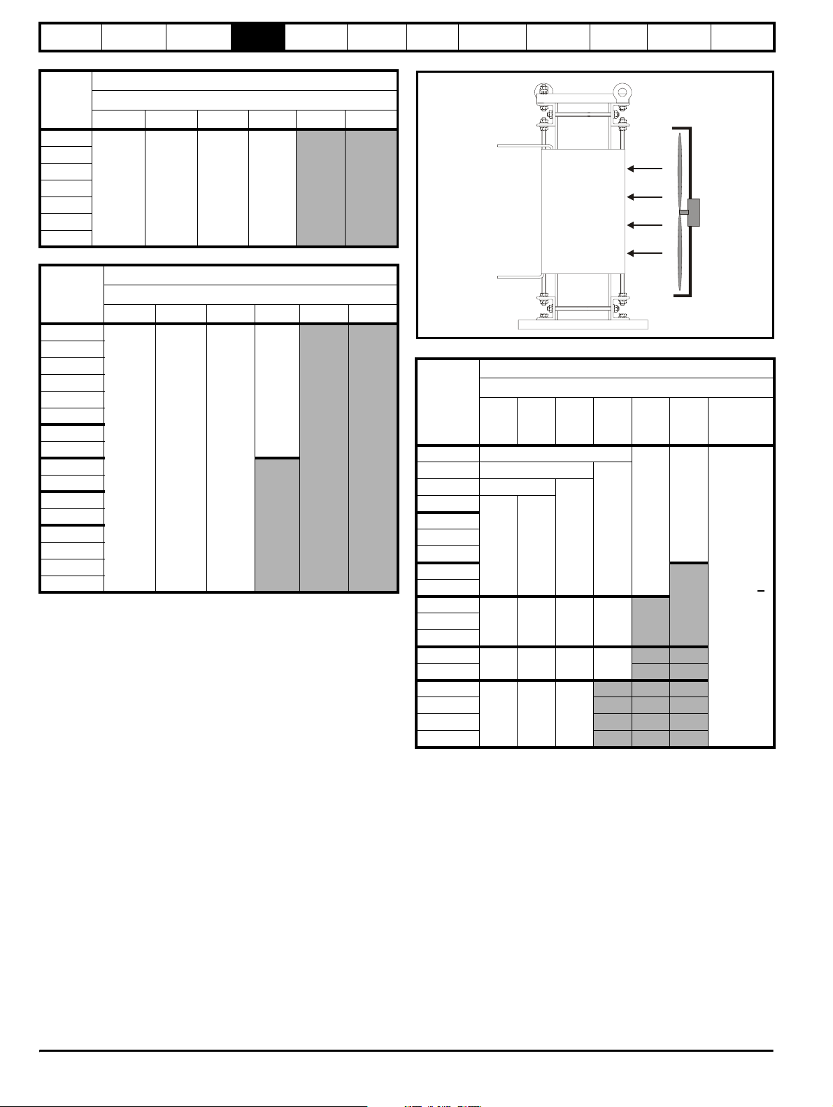
Safety
Information
Introduction
Product
information
System
design
Mechanical
installation
Electrical
installation
Table 4-7 575V Regen system maximum cable length
575V Nominal AC supply voltage
Model
Maximum permissible cable length
3kHz 4kHz 6kHz 8kHz 12kHz 16kHz
SP3501
SP3502
SP3503
SP3504
SP3505
200m
(660ft)
150m
(490ft)
100m
(330ft)
75m
(245ft)
SP3506
SP3507
Table 4-8 690V Regen system maximum cable length
690V Nominal AC supply voltage
Model
Maximum permissible cable length
3kHz 4kHz 6kHz 8kHz 12kHz 16kHz
SP4601
SP4602
SP4603
SP4604
SP4605
90m
(295ft)
SP4606
SP5601
SP5602
SP6601
200m
(660ft)
185m
(607ft)
125m
(410ft)
SP6602
SPMA1601
SPMA1602
SPMD1601
SPMD1602
SPMD1603
SPMD1604
If the cable length in the above table is exceeded, additional components
are required. Refer to section 4.6 Exceeding maximum cable length .
4.5 Cable types and lengths
Since capacitance in the cabling causes loading, ensure the cable length
does not exceed the values given.
Use 105°C (221°F) (UL 60/75°C temp rise) PVC-insulated cable with
copper conductors having a suitable voltage rating, for the following
power connections:
• AC supply to external EMC filter (when used)
• AC supply (or external EMC filter) to Regen drive
• Regen drive to motoring drive (or busbar arrangement could be
used)
• Motoring drive to motor
Getting
started
Optimisation Parameters
Technical
data
Component
sizing
Diagnostics
Figure 4-6 Location of forced cooling
Table 4-9 200V Regen system exceeding maximum cable lengths
200V Nominal AC supply voltage
Maximum permissible cable length with forced cooling
Model
3kHz 4kHz 6kHz 8kHz 12kHz 16kHz
Forced
cooling
required
SP1201 65m (210ft)
SP1202 100m (330ft)
SP1203 130m (425ft)
SP1204
SP2201
SP2202
SP2203
200m
(660ft)
150m
(490ft)
100m
(330ft)
75m
(245ft)
(165ft)
50m
37m
(120ft)
SP3201
SP3202
SP4201
SP4202
SP4203
SP5201
SP5202
65m
(210ft)
250m
(820ft)
65m
(210ft)
185m
(607ft)
65m
(210ft)
125m
(410ft)
65m
(210ft)
90m
(295ft)
Air flow >
160m3 / hr
SPMD1201
SPMD1202
SPMD1203
250m
(820ft)
185m
(607ft)
125m
(410ft)
SPMD1204
4.6 Exceeding maximum cable length
If the total maximum length specified is exceeded, the increased
circulating currents caused by the extra cable capacitance will have an
effect on the other parts of the system. This will necessitate additional
components to be added to the standard arrangement.
4.6.1 Regen inductor
If the maximum cable length specified is exceeded this will introduce
increased heating of the regen inductor. To overcome the additional
heating forced cooling should be introduced into the system as specified
in the following table.
The forced cooling should be positioned as shown below to provide the
specified airflow directly onto the regen inductor windings.
42 Unidrive SP Regen Installation Guide
www.controltechniques.com Issue Number: 2
Page 43
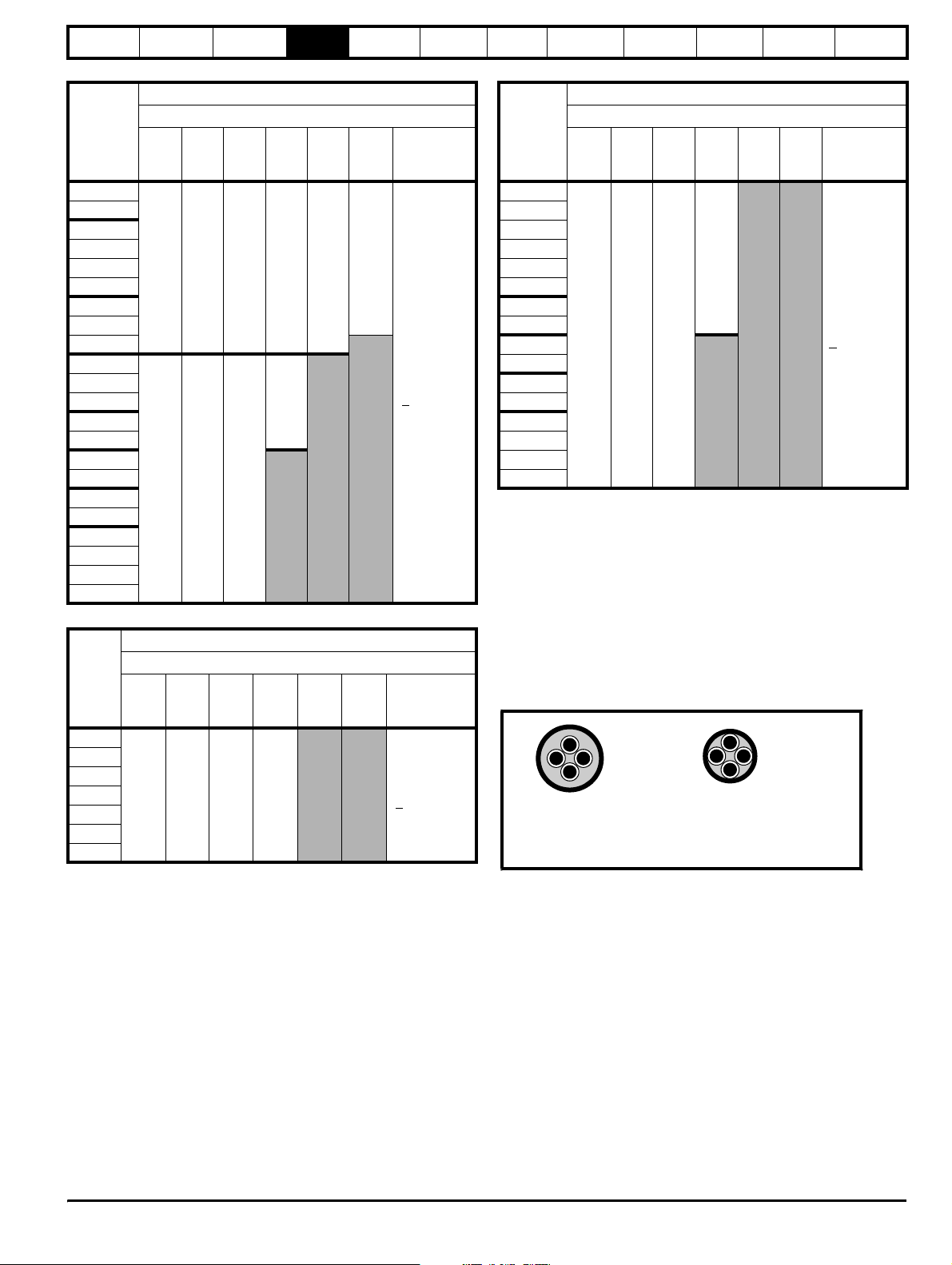
Safety
Information
Introduction
Product
information
System
design
Mechanical
installation
Table 4-10 400V Regen system maximum cable lengths
400V Nominal AC supply voltage
Maximum permissible cable length with forced cooling
Model
3kHz 4kHz 6kHz 8kHz 12kHz 16kHz
requirements
SP1405
SP1406
SP2401
SP2402
SP2403
SP2404
200m
(660ft)
150m
(490ft)
100m
(330ft)
75m
(245ft)
(165ft)
50m
37m
(120ft)
SP3401
SP3402
SP3403
SP4401
SP4402
SP4403
SP5401
90m
(295ft)
SP5402
250m
185m
SP6401
SP6402
(820ft)
(607ft)
125m
(410ft)
SPMA1401
SPMA1402
SPMD1401
SPMD1402
SPMD1403
SPMD1404
Table 4-11 575V Regen system maximum cable length
575V Nominal AC supply voltage
Maximum permissible cable length with forced cooling
Model
3kHz 4kHz 6kHz 8kHz 12kHz 16kHz
requirements
SP3501
SP3502
SP3503
SP3504
SP3505
200m
(660ft)
150m
(490ft)
100m
(330ft)
75m
(245ft)
>
SP3506
SP3507
Electrical
installation
Forced
cooling
Air flow
>
160m3 / hr
Forced
cooling
Air flow
160m3 / hr
Getting
started
Optimisation Parameters
Technical
data
Component
sizing
Diagnostics
Table 4-12 690V Regen system maximum cable length
690V Nominal AC supply voltage
Maximum permissible cable length with forced cooling
Model
3kHz 4kHz 6kHz 8kHz 12kHz 16kHz
Forced
cooling
requirements
SP4601
SP4602
SP4603
SP4604
SP4605
90m
(295ft)
SP4606
SP5601
SP5602
SP6601
200m
(660ft)
185m
(607ft)
125m
(410ft)
Air flow
160m3 / hr
>
SP6602
SPMA1601
SPMA1602
SPMD1601
SPMD1602
SPMD1603
SPMD1604
Cable lengths in excess of the above specified values may be used only
when special techniques are adopted; refer to the supplier of the drive.
4.6.2 High-capacitance cables
The maximum cable length is reduced from that shown if high
capacitance cables are used.
Most cables have an insulating jacket between the cores and the armour
or shield; these cables have a low capacitance and are recommended.
Cables that do not have an insulating jacket tend to have high
capacitance; if a cable of this type is used, the maximum cable length is
half that quoted in the tables. (Figure 4-7 shows how to identify the two
types.)
Figure 4-7 Cable construction influencing the capacitance
Normal capacitance
Shield or armour
separated from the cores
High capacitance
Shield or armour close
to the cores
The cable used is shielded and contains four cores. Typical capacitance
for this type of cable is 130pF/m (i.e. from one core to all others and the
shield connected together).
4.6.3 EMC filter
When an EMC filter is used the capacitors to ground carry common
mode current.
When the maximum cable length without additional ventilation specified
is exceeded, extra circulating currents can result in heating and
saturation of the EMC filter. To prevent this, some capacitance line to
ground should be provided as an additional path for this current, as
shown in Figure 4-8. See also section 4.4.3 Motor connection on
page 41.
Unidr ive SP Re gen Inst allatio n Guide 43
Issue Number: 2 www.controltechniques.com
Page 44
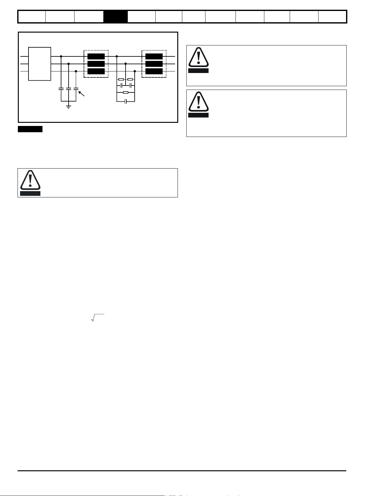
Safety
S
p
Information
Introduction
Figure 4-8 EMC filter
EMC
filter
Product
information
witching
frequency
filter inductor
System
design
Mechanical
installation
Regen
inductor
Electrical
installation
Getting
started
The I
Optimisation Parameters
is the total current line to ground, therefore each capacitor will
RMS
have to carry 4.5A.
Ground leakage current
The value of capacitance required means that the ground
leakage current exceeds the usual safety limit of 3.5mA. The
WARNING
user should be aware of the high leakage current. A
permanent fixed ground connection must be provided to the
system.
Technical
data
Component
sizing
Diagnostics
Line to
ground
capacitance
E
NOTE
If the cable length exceeds the maximum cable length with additional
Switching
frequency
filter ca
acitor
cooling, Control Techniques Technical Support must be consulted.
Whether or not an EMC filter is required is dependent upon the user
requirements and the AC supply network. For further details refer to
section 6.4 EMC (Electromagnetic compatibility) on page 77.
When using an EMC filter, a switching frequency filter must
also be used to protect the EMC filter from overload.
CAUTION
4.6.4 Line to ground capacitors for multi-drive
systems
Selection of line to ground capacitors for regen systems with long
cables.
In order to select the appropriate capacitors, the rms value of the current
line to ground, the AC supply voltage and minimum capacitance values
are required.
A minimum capacitance value of 1µF per phase should be used with the
final capacitance value being determined by the level of current line to
ground. In practice, to carry the required level of current the capacitor
will generally have a higher capacitive value. The current rating of the
capacitors should be at a high frequency such as 100kHz at the relevant
supply voltage. Polypropylene type capacitors (x type) are the most
suitable because of their low loss at high frequency.
The rms value of the current can be estimated from the following
formula:
WARNING
Discharge time
Resistors must be fitted in parallel with the capacitors to
ensure that they discharge when the supply is removed. The
resistor values should be chosen so that the discharge time
is no longer than for the drive itself. Typically values of about
5MΩ are suitable, and are high enough not to cause the
system to fail a simple insulation test.
I
2.8 104–KV
RMS
×=
×× Σlf
DC
s
Where:
k is 1 for simple rectifier-input systems, √2 for regen systems
V
is DC bus voltage
DC
∑lf
is the sum of the products of motor cable lengths and switching
s
frequencies of all drives in the system, including in the case of
regenerative systems the Regen drive with the total DC cable length
l is total cable length in m
is switching frequency in kHz
f
s
If all drives operate at 3kHz, the expression can be simplified to:
I
= 4.85 x 10
RMS
Example
A regen system operating with a supply of 400Vac giving a DC bus
-4
x K x V
DC
x √l
voltage of 620V at 3kHz switching frequency and a cable length of 1km
(motors + DC) has an I
I
= 4.85 x 10
RMS
I
= 4.85 x 10
RMS
= 13.4A
I
RMS
of:
RMS
-4
x K x V
DC
-4
x √2 x 620 x √1.000
x √l
44 Unidrive SP Regen Installation Guide
www.controltechniques.com Issue Number: 2
Page 45
Safety
Information
Introduction
Product
information
System
design
Mechanical
installation
Electrical
installation
Getting
started
Optimisation Parameters
Technical
data
Component
sizing
Diagnostics
5 Mechanical Installation
This chapter describes the installation of the Regen drive components.
Key features of this chapter include:
• Regen component dimensions
• Enclosure sizing and layout
• Enclosure ventilation
• Cubicle design with high ambient temperatures
Refer to the Mechanical Installation sections in both the Unidrive SP and
Unidrive SPM User Guides for drive mechanical information.
5.1 Safety information
Follow the instructions
The mechanical and electrical installation instructions must
be adhered to. Any questions or doubt should be referred to
WARNING
WARNING
5.2 Planning the installation
The following considerations must be made when planning the
installation:
5.2.1 Access
Access must be restricted to authorised personnel only. Safety
regulations which apply at the place of use must be complied with.
The IP (Ingress Protection) rating of the drive is installation dependent.
For further information, please refer to the Unidrive SP and Unidrive
SPM User Guides.
5.2.2 Environmental protection
The drive must be protected from:
• moisture, including dripping water or spraying water and
• contamination with electrically conductive material
• contamination with any form of dust which may restrict the fan, or
• temperature beyond the specified operating and storage ranges
5.2.3 Cooling
The heat produced by the drive / additional components must be
removed without its specified operating temperature being exceeded.
Note that a sealed enclosure gives much reduced cooling compared with
a ventilated one, and may need to be larger and/or use internal air
circulating fans.
For further information, please refer to section 5.5.2 Enclosure sizing on
page 62.
NOTE
Through hole mounting is possible for all Unidrive SP modules and the
Unidrive SPMC which can reduce cubicle heating and cooling
requirements. Refer to Unidrive SP User Guide and Unidrive SPM User
Guide.
the supplier of the equipment. It is the responsibility of the
owner or user to ensure that the installation of the drive and
any external option unit, and the way in which they are
operated and maintained, comply with the requirements of
the Health and Safety at Work Act in the United Kingdom or
applicable legislation and regulations and codes of practice in
the country in which the equipment is used.
Competence of the installer
The drive must be installed by professional assemblers who
are familiar with the requirements for safety and EMC. The
assembler is responsible for ensuring that the end product or
system complies with all the relevant laws in the country
where it is to be used.
condensation. An anti-condensation heater may be required, which
must be switched off when the drive is running.
impair airflow over various components
5.2.4 Electrical safety
The installation must be safe under normal and fault conditions.
Electrical installation instructions are given in Chapter 6 Electrical
Installation on page 65.
5.2.5 Fire protection
The drive enclosure is not classified as a fire enclosure. A separate fire
enclosure must be provided.
5.2.6 Electromagnetic compatibility
Variable speed drives are powerful electronic circuits which can cause
electromagnetic interference if not installed correctly with careful
attention to the layout of the wiring.
Some simple routine precautions can prevent disturbance to typical
industrial control equipment.
If it is necessary to meet strict emission limits, or if it is known that
electromagnetically sensitive equipment is located nearby, then full
precautions must be observed. Refer to section 6.4 EMC
(Electromagnetic compatibility) on page 77.
5.2.7 Hazardous areas
The drive must not be located in a classified hazardous area unless it is
installed in an approved enclosure and the installation is certified.
Isolation device
The AC supply must be disconnected from the drive using an
approved isolation device before any cover is removed from
WARNING
WARNING
the drive or before any servicing work is performed.
Stored charge
The drive contains capacitors that remain charged to a
potentially lethal voltage after the AC supply has been
disconnected. If the drive has been energised, the AC
supply must be isolated at least ten minutes before work
may continue.
Normally, the capacitors are discharged by an internal
resistor. Under certain, unusual fault conditions, it is possible
that the capacitors may fail to discharge, or be prevented
from being discharged by a voltage applied to the output
terminals. If the drive has failed in a manner that causes the
display to go blank immediately, it is possible the capacitors
will not be discharged. In this case, consult Control
Techniques or their authorised distributor.
Unidr ive SP Re gen Inst allatio n Guide 45
Issue Number: 2 www.controltechniques.com
Page 46
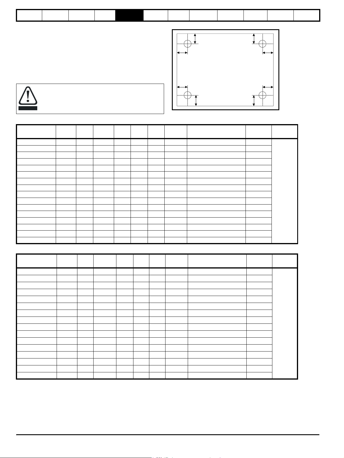
Safety
Information
Introduction
5.3 Regen component dimensions
The dimensions listed are for the following items:
• Regen inductor
• Switching frequency filter inductor
• Switching frequency filter capacitor
•Varistors
• External charging resistor (used in multiple motoring configurations)
Product
information
System
design
Mechanical
installation
Electrical
installation
Getting
started
Figure 5-1 Top view of fixing type A
Optimisation Parameters
y
x
5.3.1 Regen inductor
The following regen inductors can produce significant losses
with a normal operating temperature in the region of 170°C
dependant upon the ambient temperature. Location of the
CAUTION
Table 5-1 200V Regen inductor specifications
Inductor part
Table 5-2 400V Regen inductor specifications
Inductor part
4401-0205-00 350 0.16 2169.0 500 320 570 165 320 x 260 11
regen inductor should be considered to avoid damage to heat
sensitive components or create a fire risk.
number
4401-0310 9.6 3.5 71 215 180 200 10 120 x 140 9
4401-0311 11.0 2.7 72 215 180 200 11 120 x 140 9
4401-0312 15.5 2.2 116 215 180 200 12 120 x 140 9
4401-0313 22 1.6 157 215 180 200 15 120 x 140 9
4401-0314 31 1.10 193 270 180 240 17 160 x 140 9
4401-0315 42 0.81 200 270 200 240 24 160 x 160 9
4401-0316 56 0.6 264 325 220 320 32 200 x 180 11
4401-0317 68 0.5 299 325 220 320 33 200 x 180 11
4401-0318 80 0.4 298 325 220 320 39 200 x 180 11
4401-0319 105 0.32 338 370 260 360 55 240 x 220 11
4401-0320 130 0.26 394 375 280 360 65 240 x 240 11
4401-0321 156 0.22 475 395 280 360 77 240 x 240 11
4401-0322 192 0.18 526 395 280 360 97 240 x 240 11
4401-0323 250 0.14 610 430 300 410 110 280 x 260 11
4401-0324 312 0.11 776 430 300 410 120 280 x 260 11
4401-0325 350 0.10 863 490 320 480 130 320 x 260 11
number
4401-0001 9.5 6.32 125.0 200 180 215 12 120 x 140 9
4401-0002 12 5.00 146.0 200 180 215 14 120 x 140 9
4401-0003 16 3.75 175.0 240 180 270 17 160 x 140 9
4401-0004 25 2.40 210.0 240 180 270 24 160 x 160 9
4401-0005 34 1.76 285.0 320 220 325 32 200 x 180 11
4401-0006 40 1.50 310.0 320 220 325 33 200 x 180 11
4401-0007 46 1.30 320.0 320 220 325 39 200 x 180 11
4401-0008 60 1.00 345.0 360 260 370 55 240 x 220 11
4401-0009 70 0.78 415.0 360 260 370 65 240 x 240 11
4401-0010 96 0.63 515.0 360 260 370 75 240 x 240 11
4401-0011 124 0.48 585.0 360 260 370 95 240 x 240 11
4401-0012 156 0.38 645.0 410 300 430 110 280 x 260 11
4401-0013 180 0.33 775.0 410 300 430 120 280 x 260 11
4401-0014 200 0.30 845.0 480 320 490 130 320 x 260 11
4401-0015 300 0.20 1760.0 480 320 490 140 320 x 240 11
Amps mH
Amps mH
LossesWL
mmDmmHmm
LossesWL
mmDmmHmm
WeightkgFixing centres (x * y)
WeightkgFixing centres (x * y)
y
mm
mm
Technical
data
y
y
Fixing
mm
Fixing
mm
Component
sizing
x
xx
Fixing
Fixing
Diagnostics
type
A
type
A
46 Unidrive SP Regen Installation Guide
www.controltechniques.com Issue Number: 2
Page 47
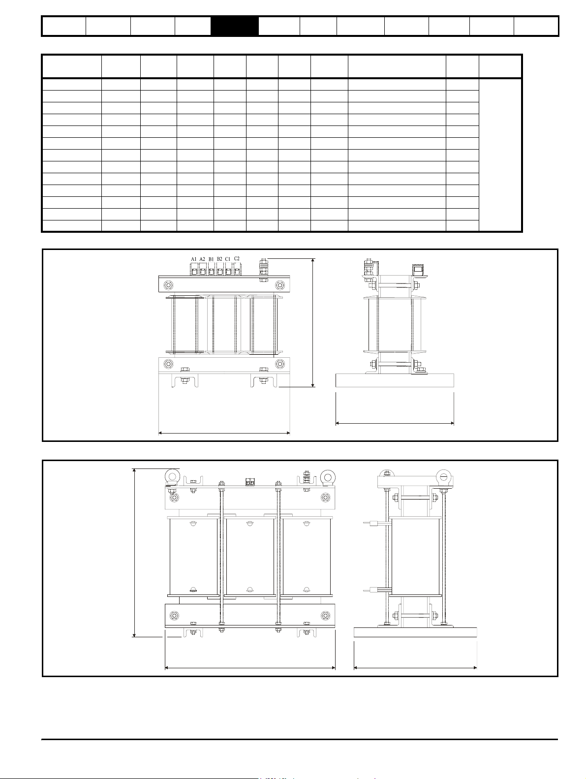
Safety
Information
Introduction
Product
information
System
design
Mechanical
installation
Electrical
installation
Getting
started
Optimisation Parameters
Technical
Table 5-3 575V / 690V Regen inductor specifications
Inductor part
number
Amps mH
LossesWL
mmDmmHmm
WeightkgFixing centres (x * y)mmFixingmmFixing
4401-0210 19 5.3 268 325 220 320 32 200 x 180 11
4401-0211 22 4.6 288 325 220 320 33 200 x 180 11
4401-0212 27 3.8 322 325 220 320 39 200 x 180 11
4401-0213 36 2.8 348 370 260 360 55 240 x 220 11
4401-0214 43 2.4 398 375 280 360 65 240 x 240 11
4401-0215 52 1.9 456 395 280 360 77 240 x 240 11
4401-0216 63 1.6 503 395 280 360 97 240 x 240 11
4401-0217 85 1.20 605 430 300 410 110 280 x 260 11
4401-0218 100 1.00 950 500 350 480 170 320 x 260 11
4401-0219 125 0.80 880 490 320 480 130 320 x 260 11
4401-0220 144 0.70 1022 500 320 480 140 320 x 260 11
4401-0221 168 0.60 1656 555 300 480 165 320 x 240 11
4401-0222 192 0.53 1350 600 350 480 180 320 x 260 11
Figure 5-2 Regen inductor type 1 dimensions
data
Component
sizing
type
A
Diagnostics
A1
A2
Figure 5-3 Regen inductor type 2 dimensions
A1 B1 C1
H
A2 B2 C2
B1
B2
C1
H
C2
D
L
TH
LD
Unidr ive SP Re gen Inst allatio n Guide 47
Issue Number: 2 www.controltechniques.com
Page 48
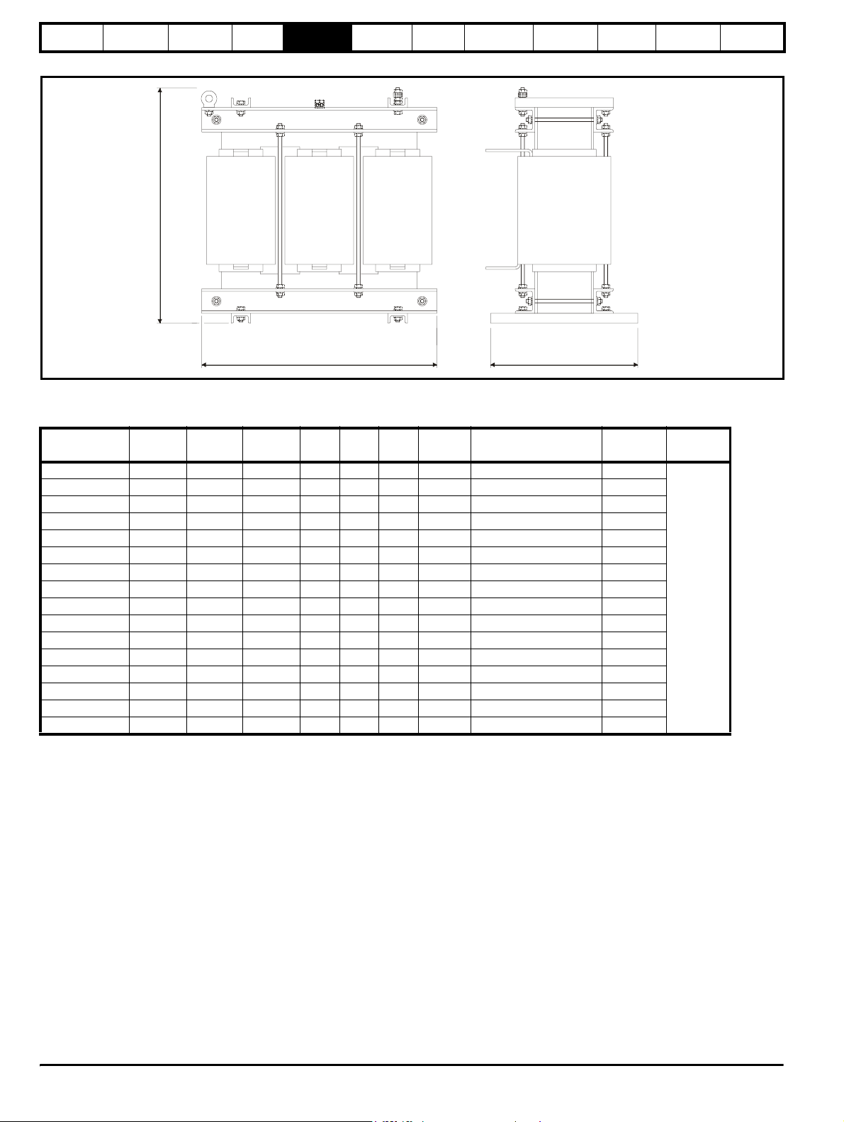
Safety
Information
Introduction
Product
information
System
design
Mechanical
installation
Electrical
installation
Getting
started
Optimisation Parameters
Technical
Figure 5-4 Regen inductor type 3 dimensions
TH
A1 B1 C1
H
A2 B2 C2
LD
5.3.2 Switching frequency filter inductor
Table 5-4 200V SFF inductor specifications
Inductor part
number
Amps mH
LossesWL
mmDmmHmm
4401-1310 9.6 0.88 10 150 90 150 4 120 x 47 8 x 18
4401-1311 11.0 1.50 18 150 90 150 4 120 x 47 8 x 18
4401-1312 15.5 1.10 26 150 90 150 4 120 x 47 8 x 18
4401-1313 22 0.70 33 150 90 150 4 120 x 47 8 x 18
4401-1314 31 0.50 37 190 100 180 6 130 x 54 8 x 20
4401-1315 42 0.40 38 190 120 180 10 130 x 74 8 x 20
4401-1316 56 0.30 48 190 160 180 12 130 x 184 8 x 20
4401-1317 68 0.25 58 190 160 180 12 130 x 184 8 x 20
4401-1318 80 0.20 60 190 160 180 13 130 x 184 8 x 20
4401-1319 105 0.16 78 255 160 240 16 200 x 180 10 x 20
4401-1320 130 0.13 86 255 170 240 20 200 x 90 10 x 20
4401-1321 156 0.11 92 255 180 240 22 200 x 100 10 x 20
4401-1322 192 0.088 97 255 190 240 25 200 x 100 10 x 20
4401-1323 250 0.068 119 300 180 300 37 204 x 113 10 x 20
4401-1324 312 0.055 170 300 180 300 37 204 x 113 10 x 20
4401-1325 350 0.048 162 300 190 300 49 204 x 123 10 x 20
WeightkgFixing centres (x * y)mmFixing
data
mm
Component
sizing
Fixing
type
B
Diagnostics
48 Unidrive SP Regen Installation Guide
www.controltechniques.com Issue Number: 2
Page 49
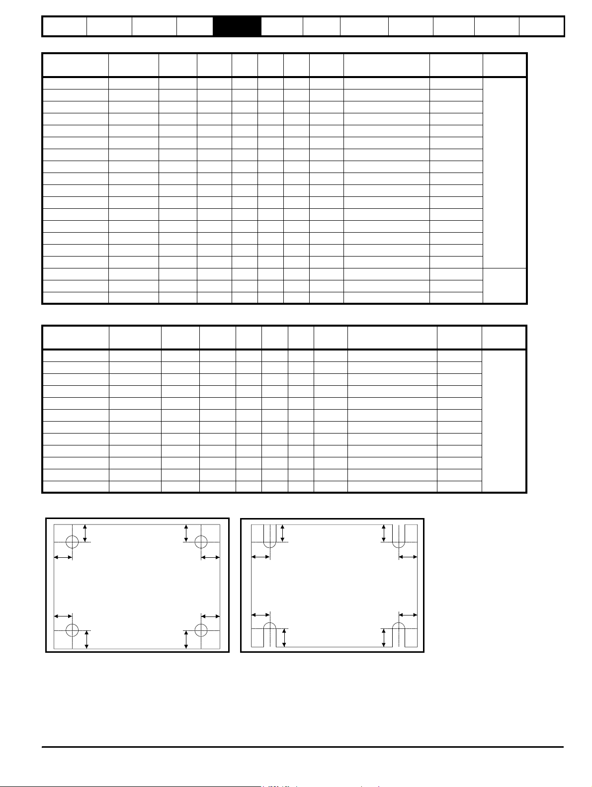
Safety
Information
Table 5-5 400V SFF inductor specifications
Inductor part
number
4401-0162 9.5 3.160 28 150 90 150 4 120 x 47 8 x 18
4401-0163 12 2.500 35 150 90 150 4 120 x 47 8 x 18
4401-0164 16 1.875 37 180 100 190 6 120 x 54 8 x 20
4401-0165 25 1.200 40 180 150 190 10 120 x 74 8 x 20
4401-0166 34 0.880 52 180 160 190 12 120 x 84 8 x 20
4401-0167 40 0.750 60 180 160 190 12 120 x 84 8 x 20
4401-0168 46 0.650 60 180 160 190 13 120 x 84 8 x 20
4401-0169 60 0.500 80 240 160 255 16 200 x 80 10 x 20
4401-0170 70 0.390 90 240 170 255 20 200 x 90 10 x 20
4401-0171 96 0.315 100 240 180 255 22 200 x 100 10 x 20
4401-0172 124 0.240 110 240 190 255 25 200 x 100 10 x 20
4401-0173 156 0.190 130 300 180 300 37 204 x 113 10 x 20
4401-0174 180 0.165 170 300 180 300 37 204 x 113 10 x 20
4401-0175 220 0.135 180 300 190 300 49 204 x 123 10 x 20
4401-0176 300 0.100 220 300 200 300 50 204 x 130 10 x 20
4401-1205 350 0.08 300 325 220 325 55 204 x 160 4 x 10
4401-0176 600 0.050 400 410 300 430 110 280 x 260 11
4401-0176 1200 0.025 700 480 320 560 170 320 x 240 11
Introduction
Product
information
Amps mH
System
design
LossesWL
Mechanical
installation
mmDmmHmm
Electrical
installation
Getting
started
WeightkgFixing centres (x * y)mmFixing
Optimisation Parameters
Technical
data
mm
Component
sizing
Fixing
type
B
A4401-0176 900 0.034 530 480 320 500 140 320 x 240 11
Diagnostics
Table 5-6 575V / 690V SFF inductor specifications
y
LossesWL
mmDmmHmm
x
y
x
Inductor part
number
4401-1211 22 1.40 36 190 120 180 10 130 x 74 8 x 20
4401-1213 36 1.40 81 255 160 240 16 200 x 80 10 x 20
4401-1214 43 1.20 86 255 170 240 20 200 x 90 10 x 20
4401-1215 52 1.00 93 255 180 240 22 200 x 100 10 x 20
4401-1216
4401-1217 85 0.60 122 300 180 300 37 204 x 113 10 x 20
4401-1218 100 0.50 190 300 180 300 37 204 x 120 4 x 10
4401-1219 125 0.40 172 300 190 300 49 204 x 123 10 x 20
4401-1220 144 0.35 177 300 200 300 50 204 x 130 10 x 20
4401-1221 168 0.30 207 300 200 300 50 204 x 130 10 x 20
4401-1222 192 0.26 220 325 220 325 55 204 x 160 4 x 10
4401-1223 192 0.21 189 300 200 300 50 204 x 130 10 x 20
Figure 5-5 Top view of fixing type A Figure 5-6 Top view of fixing type B
Amps mH
63 0.80 95 255 190 240 25 200 x 100 10 x 20
y
x
WeightkgFixing centres (x * y)mmFixing
y
x
mm
Fixing
type
B
xx
y
y
x
yy
x
Unidr ive SP Re gen Inst allatio n Guide 49
Issue Number: 2 www.controltechniques.com
Page 50
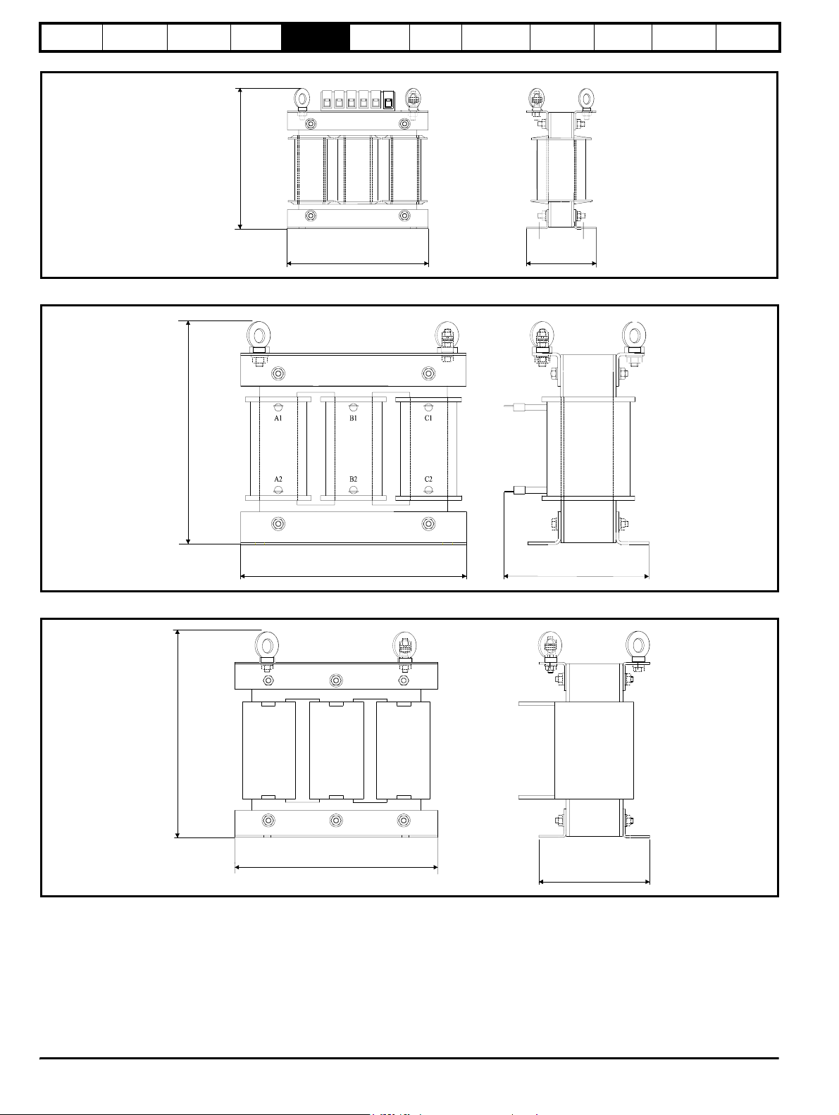
Safety
Information
Introduction
Product
information
System
design
Mechanical
installation
Electrical
installation
Figure 5-7 Switching frequency filter inductor type 1 dimensions
A1 A2 B1 B2 C1 C2
Getting
started
Optimisation Parameters
Technical
data
Component
sizing
Diagnostics
A1
B1
H
A2
B2
L
Figure 5-8 Switching frequency filter inductor type 2 dimensions
H
C1
C2
D
Figure 5-9 Switching frequency filter inductor type 3 dimensions
A1 B1
H
A2 B2 C2
L
DL
C1
D
50 Unidrive SP Regen Installation Guide
www.controltechniques.com Issue Number: 2
Page 51
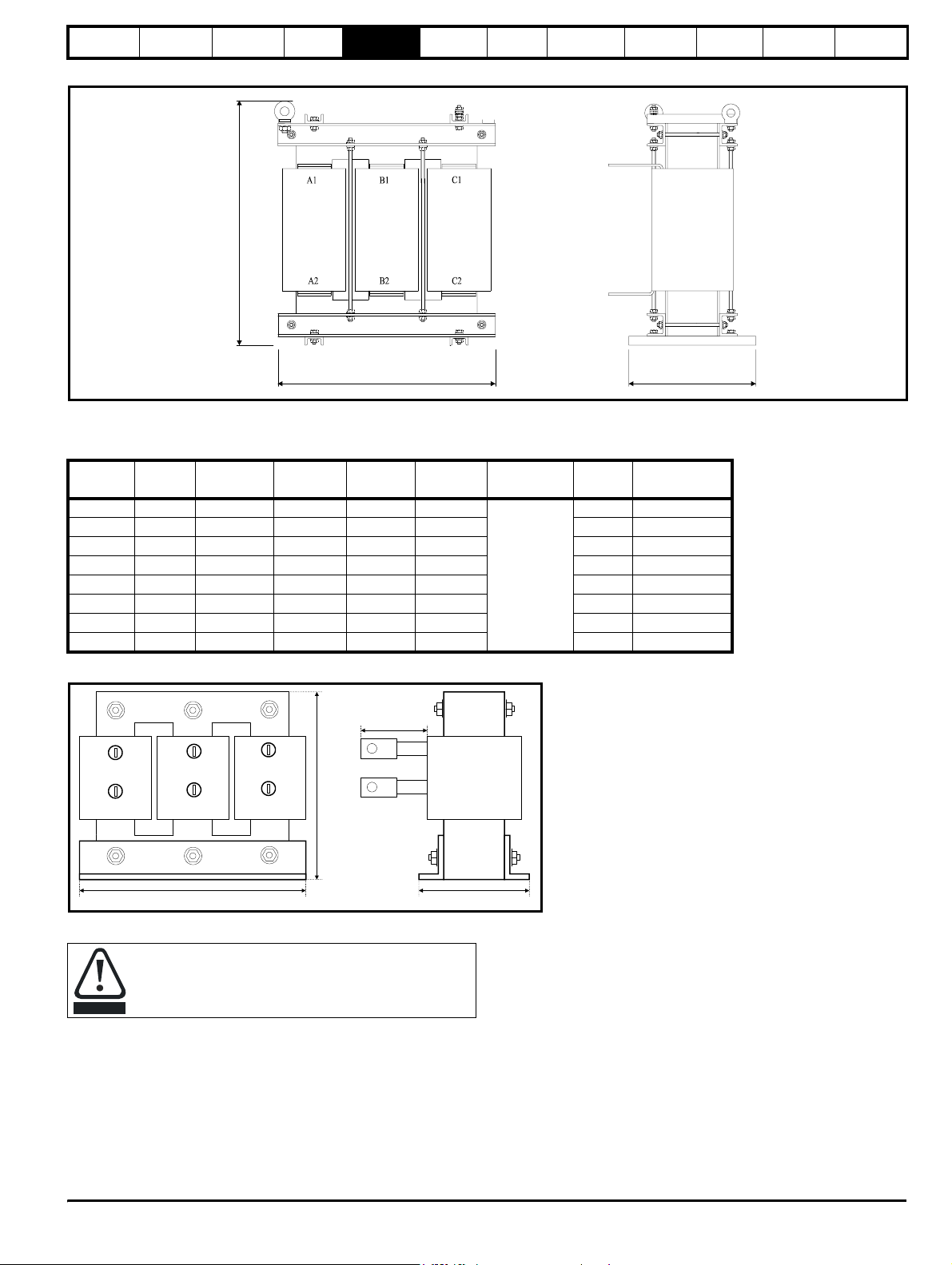
Safety
Information
Introduction
Product
information
System
design
Mechanical
installation
Electrical
installation
Getting
started
Optimisation Parameters
Figure 5-10 Switching frequency filter inductor type 4 dimensions
H
560(REF)
LD
5.3.3 Output sharing choke (for motoring drives only)
Table 5-7 400 / 600V output sharing choke ratings
Model
CurrentAInductanceµHWidth (W)mmDepth (D)mmHeight (H)mmCable length
(CLa) mm
OTL401 221 40.1 240 220 210
OTL402 267 34 242 220 205 20 4401-0198-00
OTL403 313 28.5 242 220 205 25 4401-0199-00
OTL404 378 23.9 242 220 205 25 4401-0200-00
OTL601 135 103.9 242 170 203 20 4401-0201-00
71.5
OTL602 156 81.8 242 170 203 20 4401-0202-00
OTL603 181 70.1 242 200 203 20 4401-0203-00
OTL604 207 59.2 242 200 203 20 4401-0204-00
Weight
kg
Part No.
20 4401-0197-00
Technical
data
Component
sizing
Diagnostics
Figure 5-11 OTLx0x output sharing choke
U1
U2
V1
V2
W
W1
W2
Centre tapped output sharing chokes
The OTLX1X centre tapped output sharing chokes can only
be used when two Unidrive SPM drives are paralleled
together. For all other combinations the OTLX0X output
CAUTION
sharing choke must be used.
CL(a)
M10
H
M10
D
Unidr ive SP Re gen Inst allatio n Guide 51
Issue Number: 2 www.controltechniques.com
Page 52
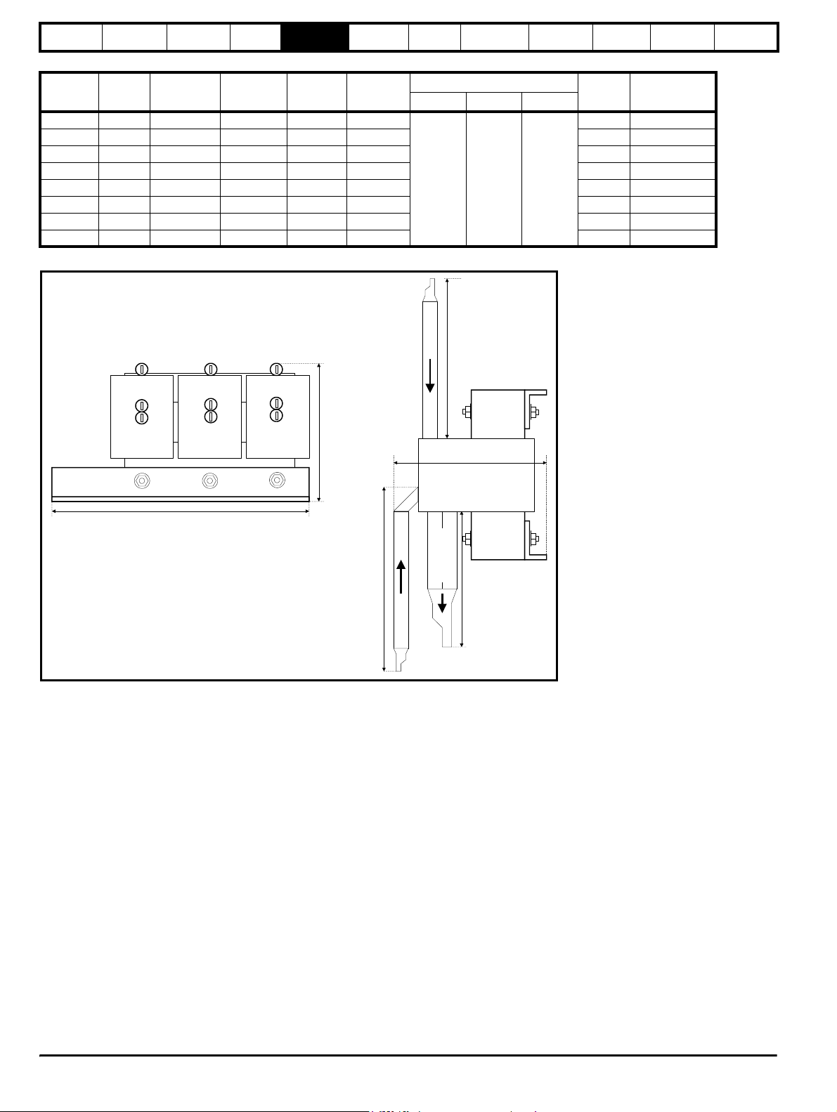
Safety
Information
Introduction
Product
information
System
design
Mechanical
installation
Electrical
installation
Getting
started
Optimisation Parameters
Technical
data
Component
sizing
Table 5-8 400 / 600V centre tapped output sharing choke ratings
Model
CurrentAInductanceµHWidth (W)mmDepth (D)mmHeight (H)
mm
OTL411 389.5 42.8 300 150 160
Cable length mm
CLa CLb CLc
Weight
kg
Part No.
8 4401-0188-00
OTL412 470.3 36.7 300 150 160 8 4401-0189-00
OTL413 551 31.1 300 150 160 8 4401-0192-00
OTL414 665 26.6 300 150 160 9 4401-0186-00
OTL611 237.5 110.4 300 150 160 8 4401-0193-00
335 335 265
OTL612 273.6 88.4 300 150 160 8 4401-0194-00
OTL613 319.2 76.7 300 150 160 8 4401-0195-00
OTL614 364.8 65.7 300 150 160 8 4401-0196-00
Figure 5-12 OTLx1x centre tapped dual output sharing choke
M10
U, V, W (b)
Diagnostics
Ua Va
U motor V motor
W
Wa
W motor
CL(b)
H
D
CL(a)
U, V, W motor
CL(c)
M10
U, V, W (a)
M10
52 Unidrive SP Regen Installation Guide
www.controltechniques.com Issue Number: 2
Page 53
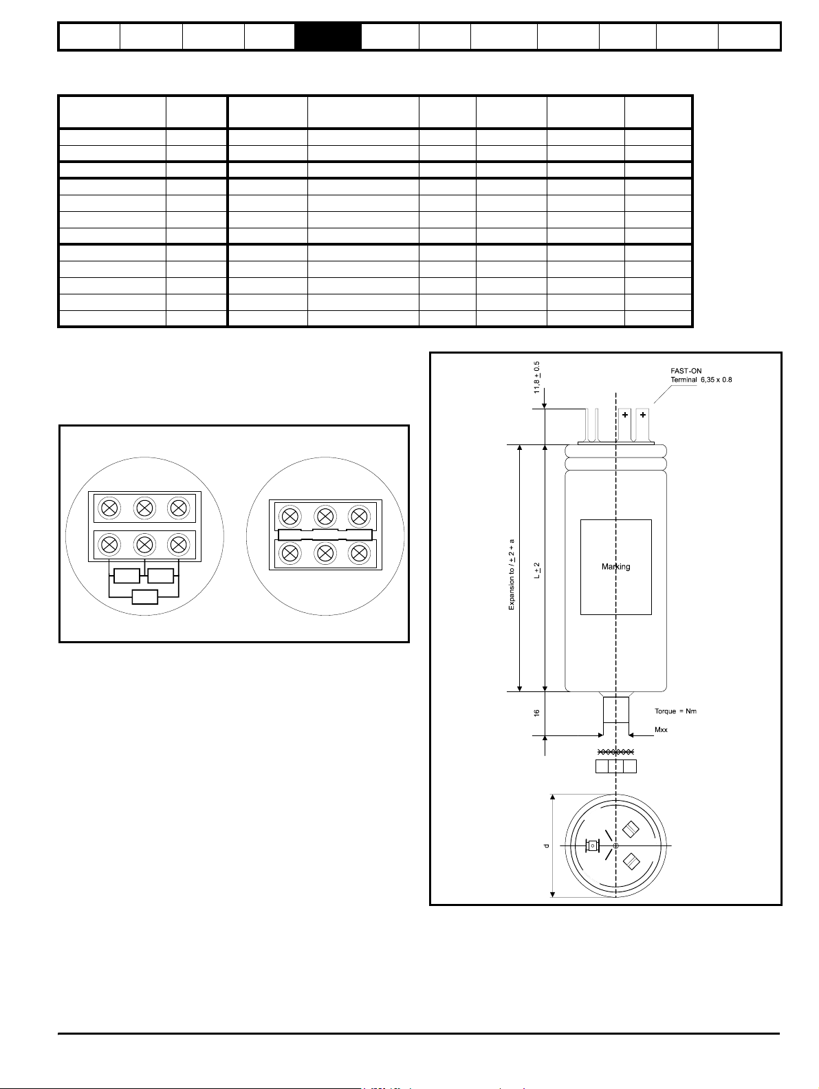
Safety
odule
Information
Introduction
Product
information
System
design
Mechanical
installation
Electrical
installation
Getting
started
Optimisation Parameters
Technical
5.3.4 Switching frequency filter capacitors
Table 5-9 Switching frequency filter capacitors
3-phase capacitor
Pt No.
CN
(uF)
∅ x L
(mm)
Discharge resistor
(kΩ)
Weight
(kg)
Mounting
1664-1074 3 x 7.0 53 x 114 390 0.3 M8 Stud 4 PHIcap
1664-2174 3 x 16.6 63.5 x 129 390 0.4 M12 Stud 10 PHIcap
1610-7804 3 x 8.0 75 x 210 390 0.5 M12 Stud 15 Polecap
1668-7833 3 x 8.3 116.2 x 204 390 1.2 M12 Stud 10 Windcap
1666-8113 3 x 11.2 116.2 x 204 390 1.3 M12 Stud 10 Windcap
1668-8163 3 x 16.6 116.2 x 204 390 1.2 M12 Stud 10 Windcap
1666-8223 3 x 22.5 116.2 x 204 390 1.4 M12 Stud 10 Windcap
1665-8324 3 x 32 116.2 x 204 390 1.1 M12 Stud 10 Phasecap
1665-8394 3 x 39 116.2 x 204 390 1.2 M12 Stud 10 Phasecap
1665-8484 3 x 48 116.2 x 204 390 1.3 M12 Stud 10 Phasecap
1664-2644 3 x 64 116.2 x 204 390 1.2 M12 Stud 10 Phasecap
1665-8774 3 x 77 116.2 x 204 390 1.8 M12 Stud 10 Phasecap
Max torque
(Nm)
data
Component
Typ e N o
sizing
Diagnostics
Discharge resistors
PoleCap capacitors have a pre-mounted ceramic discharge module, all
other capacitor types (Windcap, Phasecap or PHI capacitors) can have
either three preformed discharge resistors or a pre-mounted ceramic
discharge module supplied with capacitors.
Figure 5-13 Discharge resistor arrangement
Discharge Resistor
Arrangements
Three preformed
resistors
Ceramic discharge
m
Cautions and warnings
In case of dents of more than 2 mm depth or any other mechanical
damage, capacitors must not be used at all.
To ensure the full functionality of the overpressure disconnector, elastic
elements must not be hindered and a minimum space of 5 cm has to be
kept above each capacitor.
Protection should be provided to prevent over current and short circuit.
Discharging
Capacitors must be discharged to a maximum of 10% of rated voltage
before they are switched in again.
The capacitor must be discharged to 75 V or less within 3 minutes.
There must be not any switch, fuse or any other disconnecting device in
the circuit between the power capacitor and the discharging device.
Over current and short circuit protection
Use HRC fuses or MCCBs for short circuit protection. Short circuit
protection and connecting cables should be selected so that 1.5 times
the rated capacitor current can be permanently handled.
HRC fuses do not protect a capacitor against overload - they are only for
short circuit protection.
The HRC fuse rating should be 1.6 to 1.8 times rated capacitor current.
Figure 5-14 3-phase PHIcap dimensions
Unidr ive SP Re gen Inst allatio n Guide 53
Issue Number: 2 www.controltechniques.com
Page 54
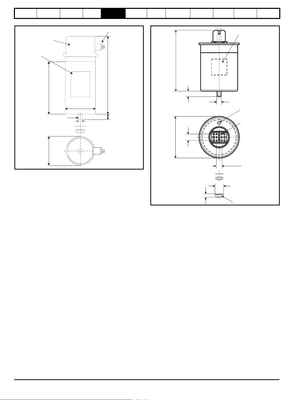
Safety
Information
Introduction
Product
information
System
design
Mechanical
installation
Electrical
installation
Getting
started
Optimisation Parameters
Technical
data
Component
sizing
Figure 5-15 3-phase Polecap dimensions Figure 5-16 3-phase Windcap / Phasecap dimensions
Terminal cover
(uv resistant)
Label
Torqu e = N m
81.2 0.3mm
±
Cable gland
L
210mm max.
L
16 +1mm
Mxx
∅
16.0 0.1mm
Mxx
±
19.6 0.5mm
±
∅
Marking
Tor q ue
T=Nm
Impregnating
Hole
To rq ue
T=1.2Nm
Diagnostics
18mm
16.8 0.5mm
±
Ø22mm
SW 17mm
54 Unidrive SP Regen Installation Guide
www.controltechniques.com Issue Number: 2
Page 55
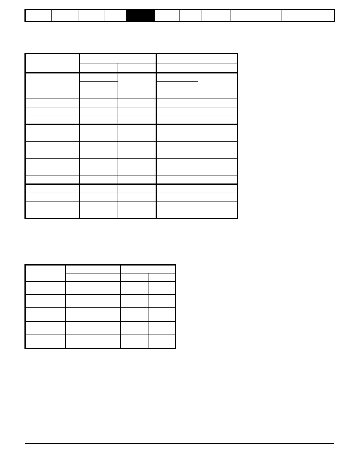
Safety
Information
Introduction
Product
information
System
design
Mechanical
installation
Electrical
installation
Getting
started
Optimisation Parameters
Technical
data
Component
sizing
Diagnostics
5.4 External EMC filter
In order to provide our customers with a degree of flexibility, external EMC filters have been sourced from two manufacturers: Schaffner & Epcos.
Filter details for each drive rating are provided in the tables below. Both the Schaffner and Epcos filters meet the same specifications.
Table 5-10 Drive EMC filter details (size 1 to 6)
Drive
CT part no. Weight CT part no. Weight
SP1201 to SP1204
4200-6118
4200-6119 4200-6120
SP2201 to SP2203 4200-6210 2.0 kg (4.4 lb) 4200-6211 3.3 kg (7.3 lb)
SP3201 to SP3202 4200-6307 3.5 kg (7.7 lb) 4200-6306 5.1 kg (11.2 lb)
SP4201 to SP4203 4200-6406 4.0 kg (8.8 lb) 4200-6405 7.8 kg (17.2 lb)
SP5201 to SP5202 4200-6503 6.8 kg (15.0 lb) 4200-6501 12.0 kg (26.5 lb)
SP1401 to SP1404 4200-6118
SP1405 to SP1406 4200-6119 4200-6120
SP2401 to SP2404 4200-6210 2.0 kg (4.4 lb) 4200-6211 3.3 kg (7.3 lb)
SP3401 to SP3403 4200-6305 3.5 kg (7.7 lb) 4200-6306 5.1 kg (11.2 lb)
SP4401 to SP4403 4200-6406 4.0 kg (8.8 lb) 4200-6405 7.8 kg (17.2 lb)
SP5401 to SP5402 4200-6503 6.8 kg (15.0 lb) 4200-6501 12.0 kg (26.5 lb)
SP6401 to SP6402 4200-6603 5.25 kg (11.6 lb) 4200-6601 10.0 kg (22.0 lb)
SP3501 to SP3507 4200-6309 3.5 kg (7.7 lb) 4200-6308 5.1 kg (11.2 lb)
SP4601 to SP4606 4200-6408 3.8 kg (8.4 lb) 4200-6407 8.0 kg (17.6 lb)
SP5601 to SP5602 4200-6504 4.4 kg (9.7 lb) 4200-6502 10.0 kg (22.0 lb)
SP6601 to SP6602 4200-6604 5.25 kg (11.6 lb) 4200-6602 8.6 kg (18.9 Ib)
Schaffner Epcos
1.4 kg (3.1 lb)
1.4 kg (3.1 lb)
4200-6121
4200-6121
2.1 kg (4.6 lb)
2.1 kg (4.6 lb)
In order to provide our customers with a degree of flexibility, external
EMC filters have been sourced from two manufacturers: Schaffner &
Epcos.
Filter details for each drive rating are provided in the tables below. Both
the Schaffner and Epcos filters meet the same specifications.
Table 5-11 Drive EMC filter details
Drive
SPMD1201 to
SPMD1204
SPMA1401 to
SPMA1402
SPMD1401 to
SPMD1404
SPMD1601 to
SPMD1602
SPMD1601 to
SPMD1604
Schaffner Epcos
CT part no. Weight CT part no. Weight
4200-6315
4200-6603
4200-6315
4200-6604
4200-6316
5.5 kg
(12.1 Ib)
5.25 kg
(11.6 lb)
5.5 kg
(12.1 Ib)
5.25 kg
(11.6 lb)
5.5 kg
(12.1 Ib)
4200-6313
4200-6601
4200-6313
4200-6602
4200-6314
8.6 kg
(18.9 Ib)
10.0 kg
(22.0 Ib)
8.6 kg
(18.9 Ib)
8.6 kg
(18.9 Ib)
8.5 kg
(18.7 Ib)
Unidr ive SP Re gen Inst allatio n Guide 55
Issue Number: 2 www.controltechniques.com
Page 56
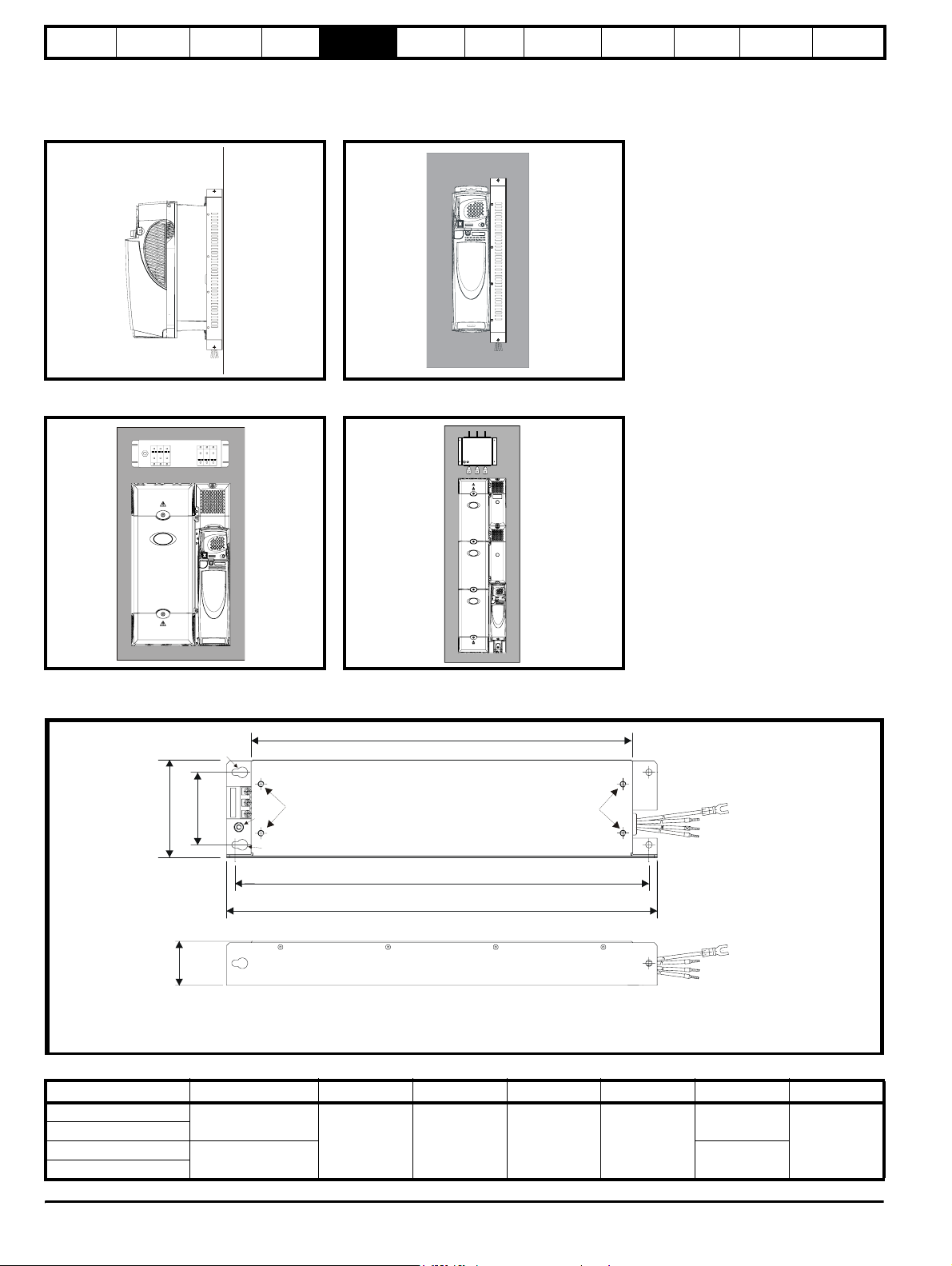
Safety
Information
Introduction
Product
information
System
design
Mechanical
installation
Electrical
installation
Getting
started
Optimisation Parameters
Technical
data
Component
sizing
Diagnostics
The external EMC filters for sizes 1 to 3 can be footprint or bookcase mounted, see Figure 5-17 and Figure 5-18. The external EMC filters for sizes 4
to 6 are designed to be mounted above the drive, as shown in Figure 5-19.
Mount the external EMC filter following the guidelines in section 4.11.5 Compliance with generic emission standards on page 88.
Figure 5-17 Footprint mounting the EMC filter Figure 5-18 Bookcase mounting the EMC filter
Figure 5-19 Size 4 to 6 mounting of EMC filter Figure 5-20
Mounting the external EMC filter
Mount the external EMC filter following the guidelines in section 6.12.5 Compliance with generic emission standards on page 62
Figure 5-21 Size 1 external EMC filter
A
Y
Z
L3L1 L2
CW
X
V
Y
B
H
X
Z
Cable size:
2
2.5mm
14AWG
DY
V: Ground stud: M5
X: M6 threaded holes for footprint mounting of the drive
Y: Footprint mounting holes 6.5mm (0.256in)
Z: Bookcase mounting holes 6.5mm (0.256in)
∅
∅
Z
All filter mounting holes are suitable for M6 fasteners.
CT part no.ManufacturerABCDHW
4200-6118
4200-6119
4200-6121
4200-6120
Schaffner
Epcos
390 mm
(15.354 in)
423 mm
(16.654 in)
74 mm
(2.913 in)
45 mm
(1.772 in)
440 mm
(17.323 in)
450 mm
(17.717 in)
100 mm
(3.937 in)
56 Unidrive SP Regen Installation Guide
www.controltechniques.com Issue Number: 2
Page 57
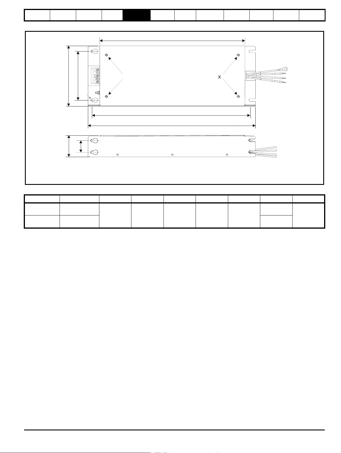
Safety
Information
Introduction
Product
information
Figure 5-22 Size 2 external EMC filter
System
design
Mechanical
installation
Electrical
installation
A
Getting
started
Optimisation Parameters
Technical
data
Component
sizing
Diagnostics
Y
L3
CW
L2
L1
V
Y
X
'
1
L
L
2
'
L
3
'
Cable size:
2
4mm
10AWG
Z
B
H
Z
ED
Y
Z
V: Ground stud: M5
X: M6 threaded holes for footprint mounting of the drive
Y: Footprint mounting holes 6.5mm (0.256in)
∅
Z: Bookcase mounting slots 6.5mm (0.256in) wide
All filter mounting holes are suitable for M6 fasteners.
CT part no. Manufacturer A B C D E H W
4200-6210 Schaffner
4200-6211 Epcos
371.5 mm
(14.626 in)
404.5 mm
(15.925 in)
125 mm
(4.921 in)
55 mm
(2.165 in)
30 mm
(1.181 in)
428.5 mm
(16.870 in)
431.5 mm
(16.988 in)
155 mm
(6.102 in)
Unidr ive SP Re gen Inst allatio n Guide 57
Issue Number: 2 www.controltechniques.com
Page 58
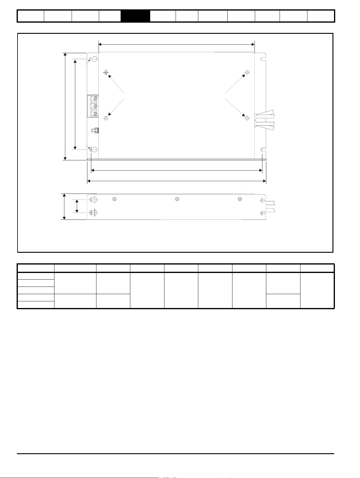
Safety
:
Information
Introduction
Product
information
Figure 5-23 Size 3 external EMC filter
Y
System
design
Mechanical
installation
Electrical
installation
A
Getting
started
Optimisation Parameters
Technical
data
Z
Component
sizing
Diagnostics
X
X
CW
V
Cable size
2
Y
16mm
6AWG
Z
B
H
ED
Z
V: Ground stud: M6
X: M6 threaded holes for footprint mounting of the drive
Y: Footprint mounting holes 6.5mm (0.256in)
∅
Z: Bookcase mounting slots 6.5mm (0.256in) wide
CT part no. Manufacturer A B C D E H W
4200-6305
4200-6307
4200-6309
4200-6306
4200-6308
Schaffner
Epcos
361 mm
(14.213 in)
365 mm
(14.370 in)
396 mm
(15.591 in)
210 mm
(8.268 in)
60 mm
(2.362 in)
30 mm
(1.181 in)
414 mm
(16.299 in)
425 mm
(16.732 in)
250 mm
(9.843 in)
58 Unidrive SP Regen Installation Guide
www.controltechniques.com Issue Number: 2
Page 59
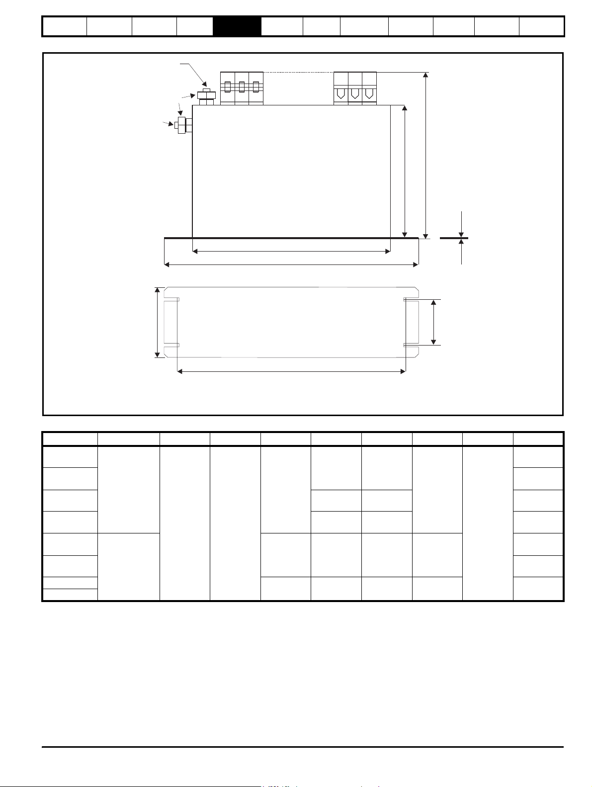
Safety
Information
Introduction
Product
information
System
design
Figure 5-24 Size 4 and 5 external EMC filter
Schaffner
V
Epcos
Mechanical
installation
Electrical
installation
A
H
Getting
started
Optimisation Parameters
C
Z
W
Technical
data
F
Component
sizing
Diagnostics
D
E
Z
B
V: Ground stud: M10
Z: Bookcase mounting slots 6.5mm (0.256in wide)
CT part no.ManufacturerABCDEFHW
4200-6406
4200-6408
4200-6503
4200-6504
4200-6405
4200-6407
4200-6501
4200-6502
Schaffner
Epcos
260 mm
(10.236 in)
275 mm
(10.827 in)
170 mm
(6.693 in)
150 mm
(5.906 in)
170 mm
(6.693 in)
100 mm
(3.937 in)
120 mm
(4.724 in)
100 mm
(3.937 in)
90 mm
(3.543in)
120 mm
(4.724 in)
65 mm
(2.559 in)
85 mm
(3.346 in)
65 mm
(2.559 in)
65 mm
(2.559 in)
85 mm
(3.346 in)
1.5 mm
(0.059in)
300 mm
(11.811 in)
2 mm
(0.079 in)
1 mm
(0.039 in)
225 mm
(8.858 in)
208 mm
(8.189 in)
249 mm
(9.803 in)
225 mm
(8.858 in)
207 mm
(8.150 in)
205 mm
(8.071 in)
249 mm
(9.803 in)
Unidr ive SP Re gen Inst allatio n Guide 59
Issue Number: 2 www.controltechniques.com
Page 60
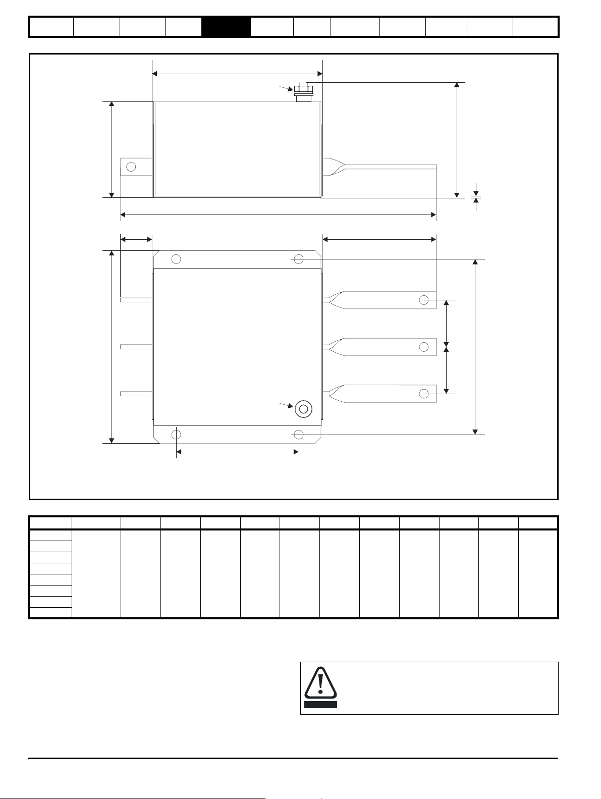
Safety
Information
Introduction
Product
information
Figure 5-25 Size 6 external EMC filter
System
design
Mechanical
installation
A
Electrical
installation
V
Getting
started
Optimisation Parameters
Technical
data
Component
sizing
Diagnostics
C
H
Z
F
W
GI
ZZ
Z
J
D
Z
E
J
Z
V
ZZ
B
V: Ground stud: M10
Z: Hole size: 10.5mm
CT part no.
4200-6601
4200-6602
4200-6603
4200-6604
4200-6313
4200-6314
4200-6315
4200-6316
Manufacturer
Schaffner
ABCDEFGH I JW
196 mm
(7.717 in)
139.9 mm
(5.508 in)
108 mm
(4.252 in)
230 mm
(9.055 in)
In order to provide our customers with a degree of flexibility, external
EMC filters have been sourced from two manufacturers: Schaffner and
Epcos. The external EMC Filter ratings and dimensions information are
available in the Unidrive SP User Guide.
For currents exceeding 300A up to 2500A, suitable filters are also
available from both Epcos and Schaffner as detailed.
• Epcos B84143-B250-5xx (range up to 2500A)
• Schaffner FN3359-300-99 (range up to 2400A)
210 mm
(8.268 in)
2 mm
(0.079in)
38 mm
(1.496 in)
136 mm
(5.354 in)
128 mm
(5.039 in)
53.5 mm
(2.106 in)
These filters may not give strict conformity with EN6000-6-4 but in
conjunction with EMC installation guidelines they will reduce emissions
to sufficiently low levels to minimise the risk of disturbance.
When a EMC filter is used, the switching frequency filter
detailed must also be used. Failure to observe this may result
in the EMC filter becoming ineffective and being damaged.
CAUTION
Refer to section 6.4 EMC (Electromagnetic compatibility) on
page 77.
364 mm
(14.331 in)
60 Unidrive SP Regen Installation Guide
www.controltechniques.com Issue Number: 2
Page 61
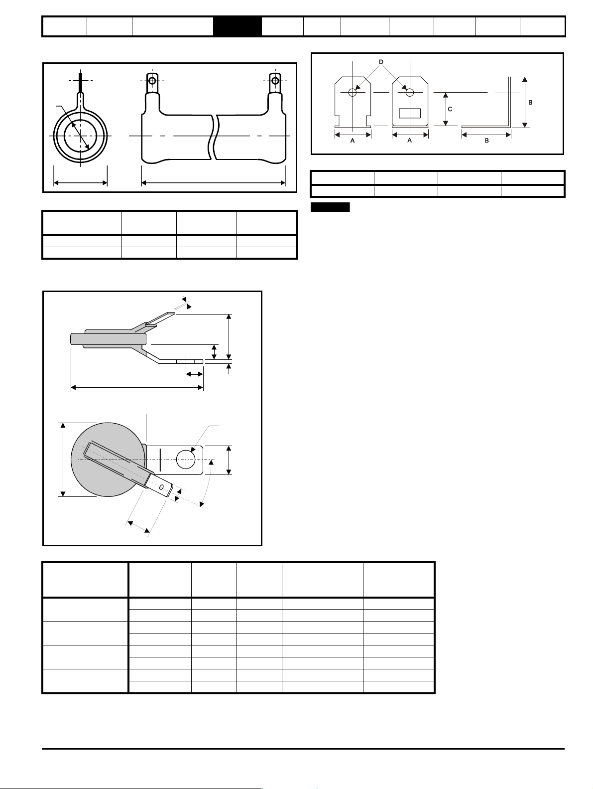
Safety
34
Information
Introduction
Product
information
System
design
Mechanical
installation
Electrical
installation
Getting
started
Optimisation Parameters
Technical
data
Component
sizing
Diagnostics
5.4.1 External charging resistor - type TG series
Figure 5-26 External charging resistor dimensions
Ø
A
B
Table 5-12 External charging resistor specifications
External charging
resistor part no.
Resistance
Diameter (A) mmLength (B)
mm
1270-3157 150Ω 19.1 73
1270-2483 48Ω x 1 22.2 165.1
5.4.2 Varistors
Figure 5-28 Varistor dimensions
1Nom
Figure 5-27 Resistor mounting bracket dimensions
Table 5-13 Resistor mounting bracket dimensions
ABCD
24.0mm 33.5mm 21.45mm±0.2 ∅5.0
NOTE
For component selection refer to either Chapter 10 Technical data on
page 183 or section 3.10 Regen components on page 25.
60 max
Coat line
max
8
m
i
n
Table 5-14 Varistor specifications
Varisto r
Drive rating
200V
(200V to 240V±10%)
400V
(380V to 480V±10%)
575V
(500V to 575V±10%)
690V
(690V±10%)
voltage rating
V
RMS
550 620 3 Line to line 2482-3291
680 760 3 Line to ground 2482-3211
550 620 3 Line to line 2482-3291
680 760 3 Line to ground 2482-3211
680 760 3 Line to line 2482-3211
1000 1200 3 Line to ground 2482-3218
385 550 6 2 in series line to line 2482-3262
1000 1200 3 Line to ground 2482-3218
21 max
6
8
5
3
.
6
8dia.hole
25°
Energy
rating
J
1.613
Quantity
per
system
Configuration CT part number
Unidr ive SP Re gen Inst allatio n Guide 61
Issue Number: 2 www.controltechniques.com
Page 62
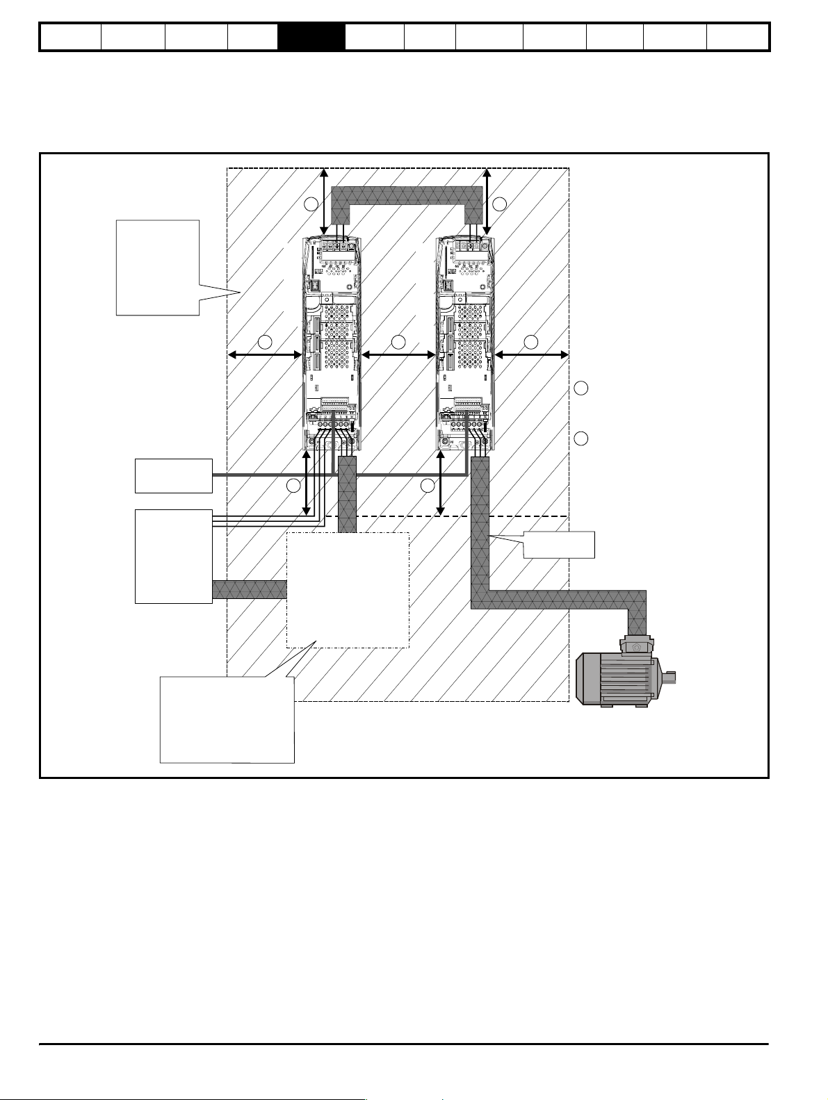
Safety
)
Information
Introduction
Product
information
System
design
Mechanical
installation
Electrical
installation
5.5 Enclosure
5.5.1 Enclosure layout
Please observe the clearances in the diagram below for the Unidrive SP
plus also take into account any clearances required for other devices /
auxiliary equipment when planning the installation.
Figure 5-29 Enclosure layout
Getting
started
Optimisation Parameters
Technical
data
Component
sizing
Diagnostics
Ensure minimum
clearances are
maintained for the
drive and external
EMC filter. Forced
or convection airflow must not be
restricted by any
object or cabling
External
controller
3 phase
AC supply,
PE, contactor
isolator
A
B B
Regen drive
B
components
Regen
±
DC bus connections
Motoring drive
B
AA
A
Size 1: 0mm (0in)
Sizes 2 to 6: 30mm (1.181in
B
≥
100mm (4in)
Standard wiring
practices apply
≥
≥
Cubicle layout must take into
account the addition regen
components required ensuring
suitable clearances are allowed.
Sensitive components should
not be placed above heat
producing components such as
the regen inductor.
5.5.2 Enclosure sizing
1. Add the dissipation figures from Chapter 10 Technical data for each
drive that is to be installed in the enclosure.
2. Calculate the total heat dissipation (in Watts) of any other equipment
to be installed in the enclosure.
• EMC filter
• Switching frequency filter
• Regen choke
3. Add the heat dissipation figures obtained above. This gives a figure
in Watts for the total heat that will be dissipated inside the enclosure.
Calculating the size of a sealed enclosure
The enclosure transfers internally generated heat into the surrounding
air by natural convection (or external forced air flow); the greater the
surface area of the enclosure walls, the better is the dissipation
capability. Only the surfaces of the enclosure that are unobstructed (not
in contact with a wall or floor) can dissipate heat.
Calculate the minimum required unobstructed surface area A
enclosure from:
A
e
P
-----------------------------------=
–()
kT
intText
Where:
A
Unobstructed surface area in m2 (1 m2 = 10.9 ft2)
e
T
Maximum expected temperature in
ext
o
C outside the
enclosure
T
Maximum permissible temperature in oC inside the
int
enclosure
P Power in Watts dissipated by all heat sources in the
enclosure
k Heat transmission coefficient of the enclosure material
2/o
in W/m
C
for the
e
62 Unidrive SP Regen Installation Guide
www.controltechniques.com Issue Number: 2
Page 63
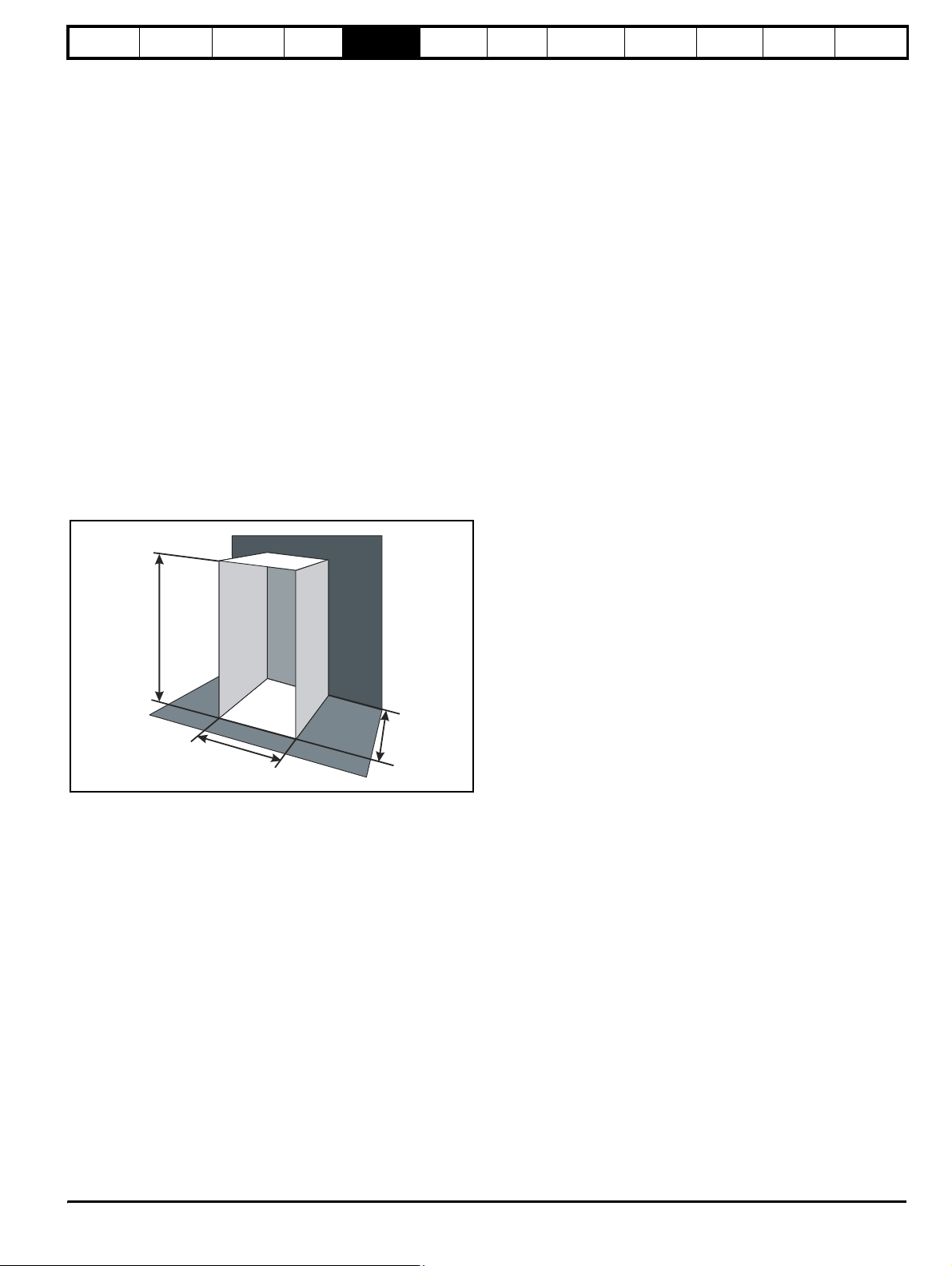
Safety
Information
Introduction
Product
information
System
design
Mechanical
installation
Electrical
installation
Example
To calculate the size of a non-ventilated enclosure for the following:
• Two SP 1405 (1 x Regen and 1 x motoring drive) models
operating at the Normal Duty rating
• Each drive to operate at 6kHz PWM switching frequency
• Schaffner 16 A (4200-6119) external EMC filter for each drive
• Maximum ambient temperature inside the enclosure: 40°C
• Maximum ambient temperature outside the enclosure: 30°C
Dissipation of each drive: 147 W (see Chapter 12 Technical Data in the
Unidrive SP User Guide)
Dissipation of external EMC filter: 9.2 W (max) (see Chapter 12
Tech n i c a l D a ta in the Unidrive SP User Guide)
Dissipation of each external regen inductor: 125 W x 1 (see section
10.4.1 Regen inductors on page 196)
Dissipation of external switching frequency filter: 28 W x 1 (see Chapter
10 Technical data on page 183)
Total dissipation: ((147 x 2) + 9.2 + 125 + 28) = 456.2 W
The enclosure is to be made from painted 2 mm (0.079 in) sheet steel
having a heat transmission coefficient of 5.5 W/m
2/o
C. Only the top,
front, and two sides of the enclosure are free to dissipate heat.
2
The value of 5.5 W/m
/ºC can generally be used with a sheet steel
cubicle (exact values can be obtained by the supplier of the material). If
in any doubt, allow for a greater margin in the temperature rise.
Figure 5-30 Enclosure having front, sides and top panels free to
dissipate heat
H
D
W
Insert the following values:
T
40°C
int
30°C
T
ext
k 5.5
P 456.2 W
The minimum required heat conducting area is then:
A
= 8.294 m
456.2
---------------------------------=
e
5.5 40 30–()
2
(90.36 ft2) (1 m2 = 10.9 ft2)
Estimate two of the enclosure dimensions - the height (H) and depth (D),
for instance. Calculate the width (W) from:
2HD–
A
e
--------------------------=
W
HD+
Inserting H = 2m and D = 0.6m, obtain the minimum width:
10.72 2 2× 0.6×()–
W
-----------------------------------------------------=
20.6+
=3.2 m (126.02 in)
Getting
started
Optimisation Parameters
Technical
data
Component
sizing
Diagnostics
If the enclosure is too large for the space available, it can be made
smaller only by attending to one or all of the following:
• Using a lower PWM switching frequency to reduce the dissipation in
the drives
• Reducing the ambient temperature outside the enclosure, and/or
applying forced-air cooling to the outside of the enclosure
• Reducing the number of drives in the enclosure
• Removing other heat-generating equipment
Calculating the air-flow in a ventilated enclosure
The dimensions of the enclosure are required only for accommodating
the equipment. The equipment is cooled by the forced air flow.
Calculate the minimum required volume of ventilating air from:
3kP
V
---------------------------=
T
–
intText
Where:
V Air-flow in m
T
Maximum expected temperature in °C outside the
ext
enclosure
T
Maximum permissible temperature in °C inside the
int
enclosure
P Power in Watts dissipated by all heat sources in the
enclosure
k Ratio of
Where:
P
is the air pressure at sea level
0
is the air pressure at the installation
P
I
Typically use a factor of 1.2 to 1.3, to allow also for pressure-drops in
dirty air-filters.
Example
To calculate the size of an enclosure for the following:
• Two SP1406 (1 x Regen and 1 x motoring drive) models
operating at the Normal Duty rating
• Each drive to operate at 6kHz PWM switching frequency
• Schaffner 16A (4200-6119) external EMC filter for each drive
• Maximum ambient temperature inside the enclosure: 40°C
• Maximum ambient temperature outside the enclosure: 30°C
Dissipation of each drive: 147 W (see Chapter 12 Technic a l D a t a in the
Unidrive SP User Guide)
Dissipation of external EMC filter: 9.2 W (max) (see Chapter 12
Technical Data in the Unidrive SP User Guide)
Dissipation of external regen inductor: 125 W x 1 (see section
10.4.1 Regen inductors on page 196)
Dissipation of external switching frequency filter: 28 W x 1 (see Chapter
10 Technical data on page 183)
Total dissipation: ((147 x 2) + (9.2 + 125 + 28) = 456.2 W
Insert the following values:
T
40°C
int
30°C
T
ext
k 1.3
P 456.2 W
Then:
21.3× 456.2×
V
---------------------------------------=
= 118.6 m
3
per hour (1 m3/hr = 0.59 ft3/min)
P
o
-------
P
l
40 30–
3
/hr (70.05 ft3 /min) (1 m3/ hr = 0.59 ft3/min)
Unidr ive SP Re gen Inst allatio n Guide 63
Issue Number: 2 www.controltechniques.com
Page 64
Safety
Information
Introduction
Product
information
System
design
Mechanical
installation
Electrical
installation
5.6 Cubicle design and drive ambient temperature
Drive derating is required for operation in high ambient temperatures
(derating information is provided in the Unidrive SP User Guide).
Totally enclosing or through panel mounting the drive in either a sealed
cabinet (no airflow) or in a well ventilated cabinet makes a significant
difference on drive cooling.
The chosen method affects the ambient temperature value (T
should be used for any necessary derating to ensure sufficient cooling
for the whole of the drive.
The ambient temperature for the four different combinations is defined
below:
1. Totally enclosed with no air flow (<2 m/s) over the drive
T
= T
rate
+ 5°C
int
2. Totally enclosed with air flow (>2 m/s) over the drive
T
= T
rate
int
3. Through panel mounted with no airflow (<2 m/s) over the drive
T
= the greater of T
rate
+5°C, or T
ext
int
4. Through panel mounted with air flow (>2 m/s) over the drive
T
= the greater of T
rate
ext
or T
int
Where:
= Temperature outside the cabinet
T
ext
= Temperature inside the cabinet
T
int
= Temperature used to select current rating from tables in
T
rate
Chapter 10 Technical data on page 183.
rate
) which
Getting
started
Optimisation Parameters
Technical
data
Component
sizing
Diagnostics
CAUTION
Regen inductors can produce significant losses with a normal
operating temperature in the region of 150°C dependant
upon the ambient temperature. Location of the regen
inductors should be considered to prevent damage to heat
sensitive components or create a fire risk.
64 Unidrive SP Regen Installation Guide
www.controltechniques.com Issue Number: 2
Page 65
Safety
Information
Introduction
Product
information
System
design
Mechanical
installation
6 Electrical Installation
Electric shock risk
The voltages present in the following locations can cause
severe electric shock and may be lethal:
WARNING
WARNING
WARNING
• AC supply cables and connections
• DC connections
• Output cables and connections
• Many internal parts of the drive, and external option units
Unless otherwise indicated, control terminals are single
insulated and must not be touched.
Isolation device
The AC supply must be disconnected from the drive using
an approved isolation device before any cover is removed
from the drive or before any servicing work is performed.
Stored charge
The drive contains capacitors that remain charged to a
potentially lethal voltage after the AC supply has been
disconnected. If the drive has been energised, the AC
supply must be isolated at least ten minutes before work
may continue.
Normally, the capacitors are discharged by an internal
resistor. Under certain, unusual fault conditions, it is possible
that the capacitors may fail to discharge, or be prevented
from being discharged by a voltage applied to the output
terminals. If the drive has failed in a manner that causes the
display to go blank immediately, it is possible the capacitors
will not be discharged. In this case, consult Control
Techniques or their authorised distributor.
Electrical
installation
Getting
started
Optimisation Parameters
Te ch n ic a l
data
Component
sizing
Diagnostics
WARNING
Equipment supplied by plug and socket
Special attention must be given if the drive is installed in
equipment which is connected to the AC supply by a plug
and socket. The AC supply terminals of the drive are
connected to the internal capacitors through rectifier diodes
which are not intended to give safety isolation. If the plug
terminals can be touched when the plug is disconnected
from the socket, a means of automatically isolating the plug
from the drive must be used (e.g. a latching relay).
Unidr ive SP Re gen Inst allatio n Guide 65
Issue Number: 2 www.controltechniques.com
Page 66

Safety
connectio
Information
Introduction
Product
information
System
design
Mechanical
installation
Electrical
installation
6.1 Power connections
6.1.1 AC and DC regen connections
Figure 6-1 Unidrive SP size 1 Regen drive power connections
DC connections
(High current DC to motoring drive[s])
Getting
started
Optimisation Parameters
Te ch ni ca l
data
Component
sizing
Diagnostics
BR48V -DC +DC
Internal
EMC filter
To b e
removed
Regen drive
1
AC supply connections
L2L1 L3 U V W
PE
BR48V -DC +DC
Internal
EMC filter
To b e
removed
Motoring drive
1
Motor connections
L2L1 L3 U V W
PE
L1, L2, L3
(Refer to Chapter 4
System design)
Motor
Vac supply
Optional ground
n
66 Unidrive SP Regen Installation Guide
www.controltechniques.com Issue Number: 2
Page 67
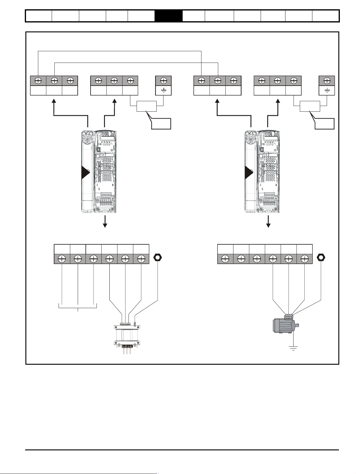
Safety
connectio
Information
Introduction
Product
information
System
design
Mechanical
installation
Figure 6-2 Unidrive SP size 2 power connections
Electrical
installation
DC connections
(High current DC to motoring drive[s])
Getting
started
Optimisation Parameters
Te ch n ic a l
data
Component
sizing
Diagnostics
DC1 =
DC2 = +
BRDC1 DC2 48V -DC +DC
-
Internal
EMC filter
To b e
removed
DC1 =
DC2 = +
-
Regen drive
2
AC supply connections
L2L1 L3 U V W PE
BRDC1 DC2
48V -DC +DC
Motoring drive
2
Motor connections
L2L1 L3 U V W PE
Internal
EMC filter
To b e
removed
L1, L2, L3
(Refer to Chapter 4
)System design
Motor
Vac supply
Optional ground
n
If the heatsink mounted resistor is used (size 1 and 2 only), an overload
protection device is not required. The resistor is designed to fail safely
under fault conditions.
See Figure 6-8 for further information on ground connections.
Unidr ive SP Re gen Inst allatio n Guide 67
Issue Number: 2 www.controltechniques.com
Page 68
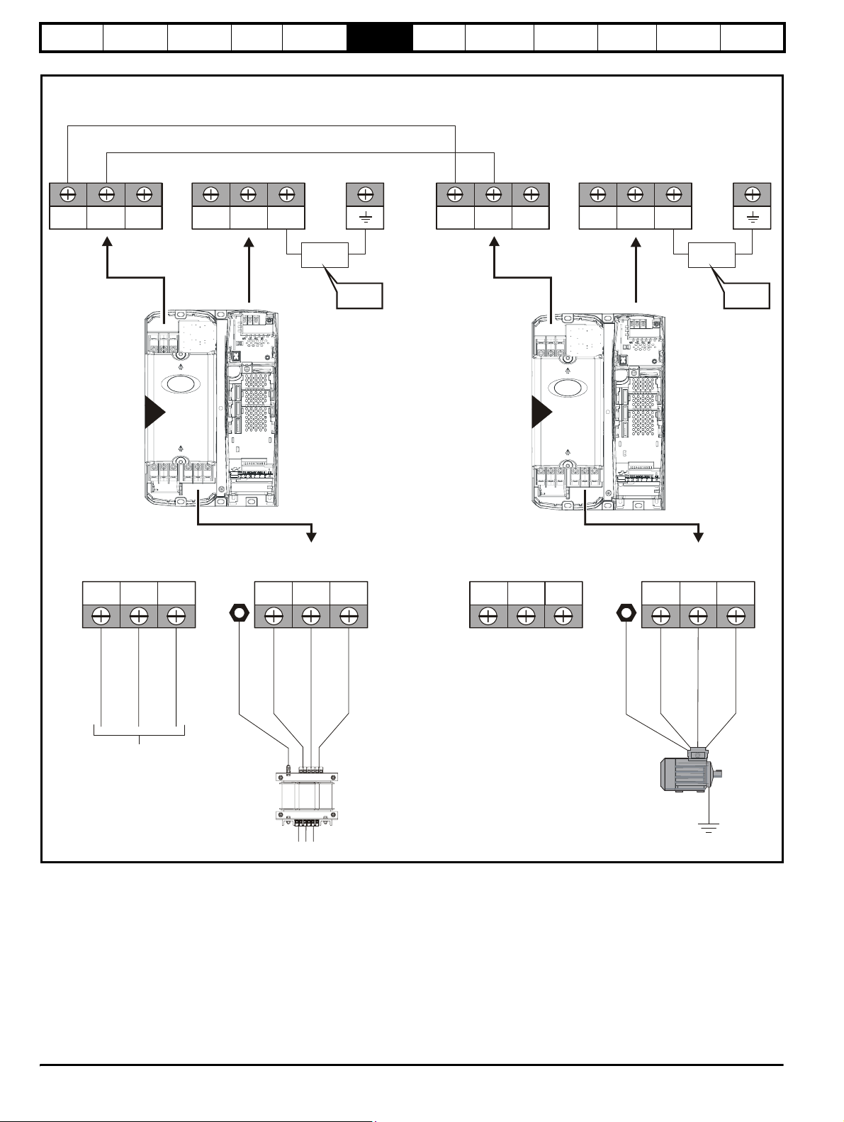
Safety
connectio
Information
Introduction
Product
information
System
design
Mechanical
installation
Figure 6-3 Unidrive SP size 3 power connections
Electrical
installation
DC connections
(High current DC to motoring drive[s])
Getting
started
Optimisation Parameters
Te ch ni ca l
data
Component
sizing
Diagnostics
DC1 =
DC2 = +
BRDC1 DC2
-
Regen drive
3
L2L1 L3 U V WPE
48V -DC +DC
AC supply connections
Internal
EMC filter
To b e
removed
DC1 =
DC2 = +
BRDC1 DC2 48V -DC +DC
-
Internal
EMC filter
To b e
removed
Motoring drive
3
Motor connections
L2L1 L3 U V WPE
L1, L2, L3
(Refer to Chapter 4
)System design
Motor
Vac su pp ly
Optional ground
n
On Unidrive SP size 2 and 3, the high current DC connections must
always be used when using a braking resistor, supplying the drive from
DC (low voltage 48V or high voltage) or using the drive in a parallel DC
bus system. The low current DC connection is used only to connect the
internal EMC filter.
See Figure 6-9 for further information on ground connections.
68 Unidrive SP Regen Installation Guide
www.controltechniques.com Issue Number: 2
Page 69
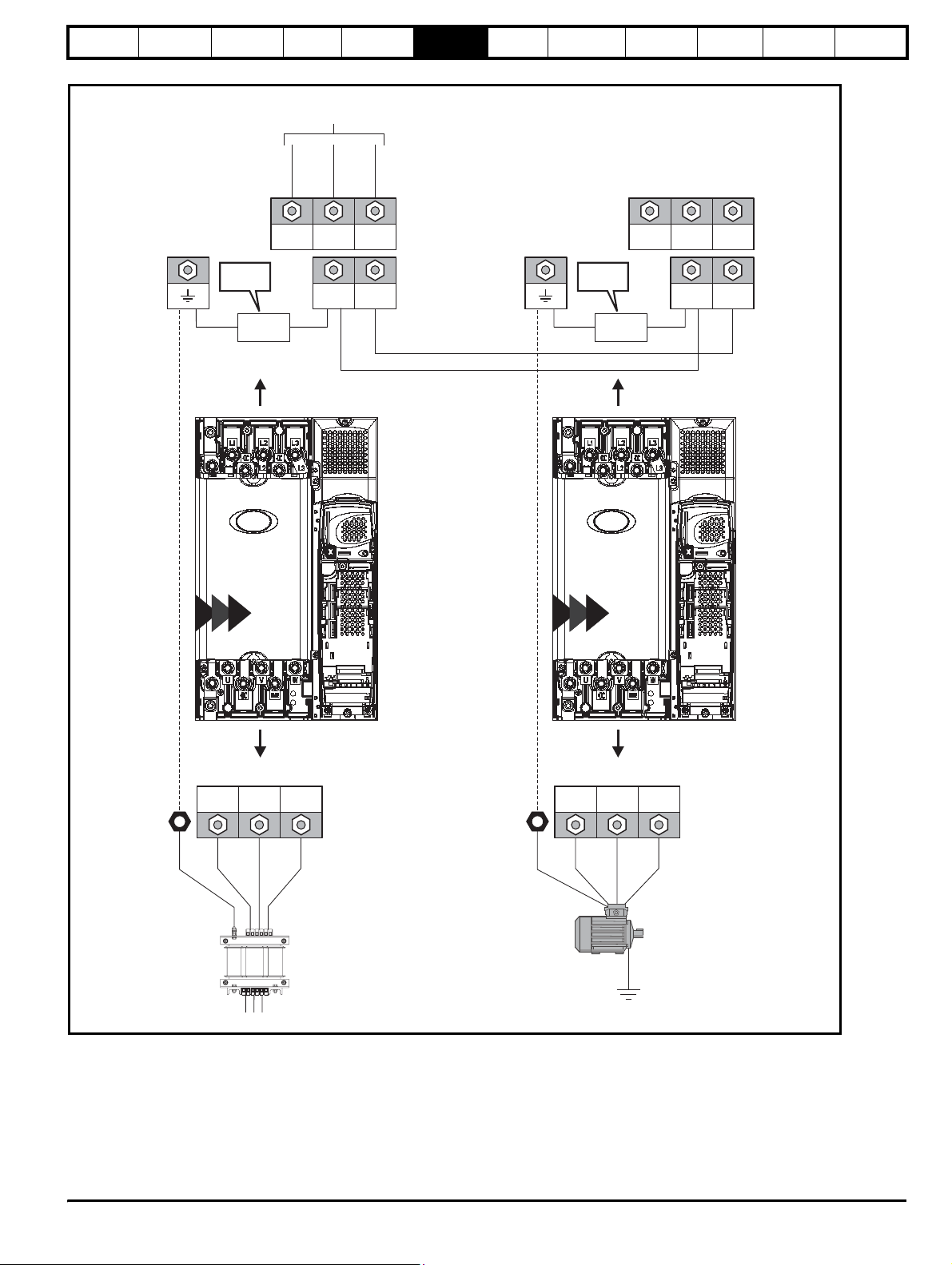
Safety
Information
Introduction
Product
information
System
design
Mechanical
installation
Figure 6-4 Unidrive SP size 4, 5 and 6 power connections
(Refer to Chapter 4
System design
L1, L2, L3
)
Electrical
installation
Getting
started
Optimisation Parameters
Te ch n ic a l
data
Component
sizing
Diagnostics
L1 L2 L3
To be
removed
To be
removed
+DC -DC
*
Internal
EMC filter
DC Connections
(High current DC
to motoring drive[s])
*
Regen drive
4
5 6
4
5 6
L1 L2 L3
Internal
EMC filter
+DC -DC
Motoring drive
AC supply connections
PE
UVW
*
Vac supply
PE
UVW
*
Motor
Optional ground
connection
* See section 6.1.2 Ground connections .
Unidr ive SP Re gen Inst allatio n Guide 69
Issue Number: 2 www.controltechniques.com
Page 70
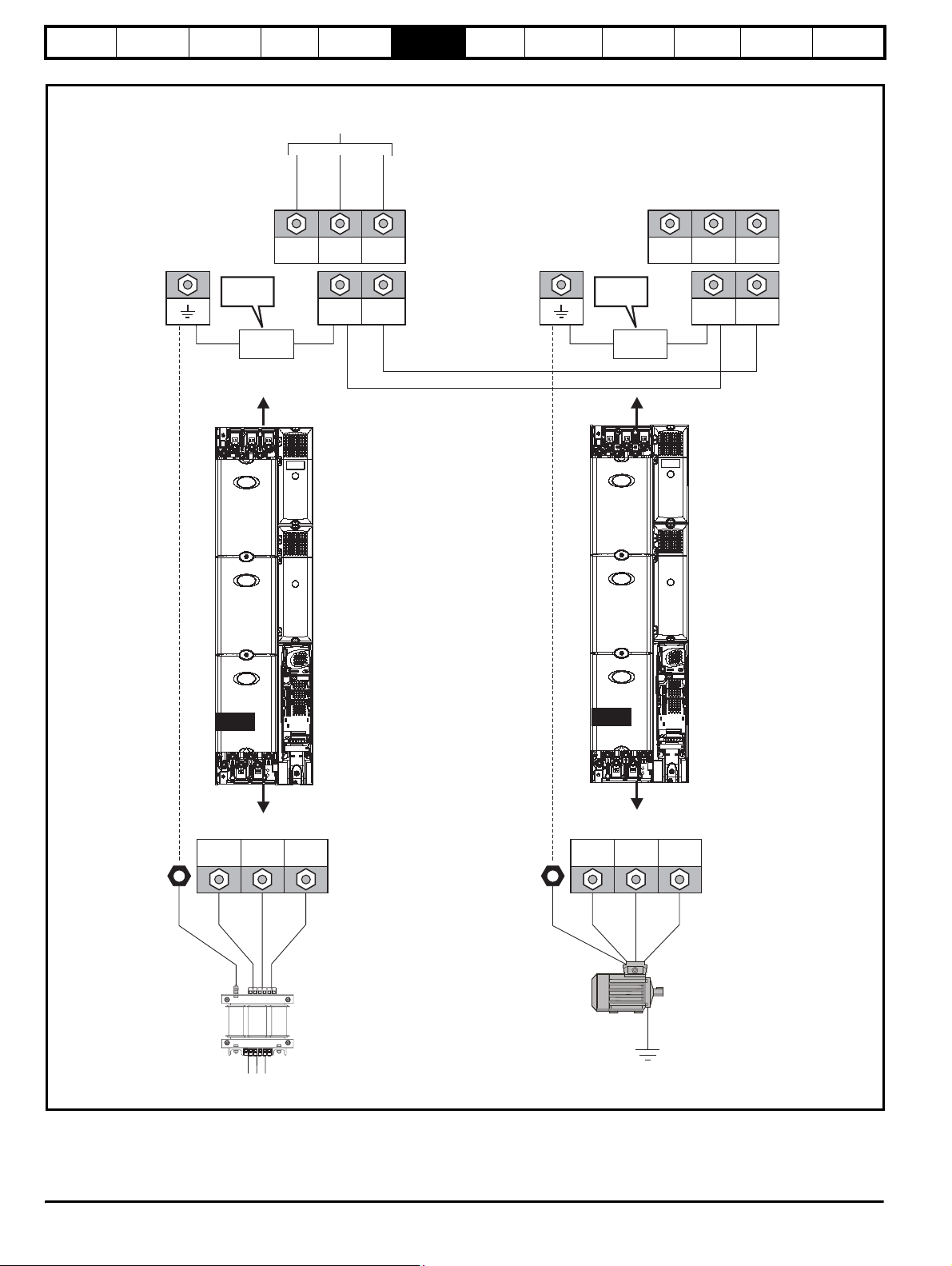
Safety
Information
Introduction
Product
information
System
design
Figure 6-5 Unidrive SPMA power connections
Mechanical
installation
Electrical
installation
Getting
started
Optimisation Parameters
Te ch ni ca l
data
Component
sizing
Diagnostics
(Refer to Chapter 4
System design
L1, L2, L3
L1 L2 L3
To be
removed
*
Internal
EMC filter
)
+DC -DC
DC Connections
(High current DC
to motoring drive[s])
L1 L2 L3
To be
removed
+DC -DC
*
Internal
EMC filter
Motoring drive
Regen drive
SPMA
AC supply connections
UVW
*
PE
Vac supply
PE
4
56
SPMA
Motor connections
UVW
*
Motor
Optional ground
connection
70 Unidrive SP Regen Installation Guide
www.controltechniques.com Issue Number: 2
Page 71
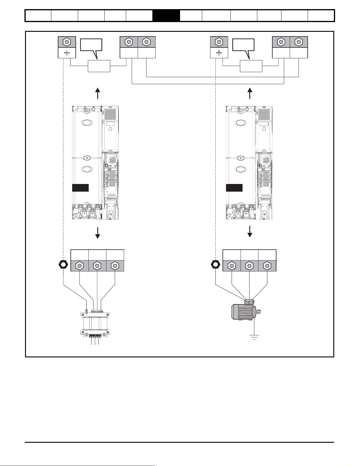
Safety
Information
Figure 6-6 Unidrive SPMD power connections
Introduction
Product
information
System
design
Mechanical
installation
Electrical
installation
Getting
started
Optimisation Parameters
Te ch n ic a l
data
Component
sizing
Diagnostics
To b e
removed
+DC -DC
*
Internal
EMC filter
DC Connections
(High current DC
to motoring drive[s])
*
To b e
removed
Internal
EMC filter
+DC -DC
Motoring drive
Regen drive
4
SPMD
56
SPMD
PE
SPMA
AC supply connections
*
UVW
Vac supply
PE
Motor connections
*
UVW
Motor
Optional ground
connection
Unidr ive SP Re gen Inst allatio n Guide 71
Issue Number: 2 www.controltechniques.com
Page 72
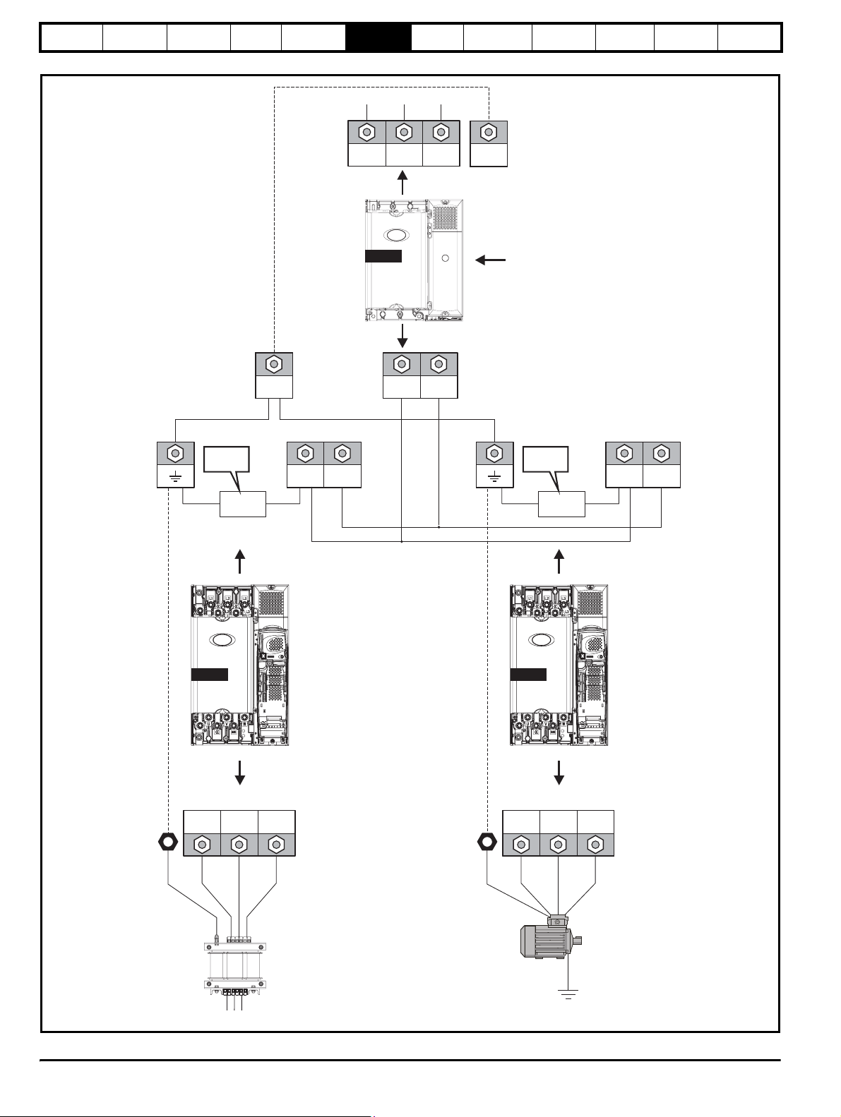
Safety
Information
Introduction
Product
information
System
design
Figure 6-7 Unidrive SPMC power connections
Mechanical
installation
Electrical
installation
Getting
started
Optimisation Parameters
Te ch ni ca l
data
Component
sizing
Diagnostics
L1 L2 L3
SPMC
PE
Used as only
softstart
+DC -DCPE
To be
removed
+DC -DC
*
Internal
EMC filter
DC Connections
(High current DC
to motoring drive[s])
*
To be
removed
Internal
EMC filter
+DC -DC
SPMD SPMD
56
AC supply connections
UVW
*
PE
Vac supply
* See section 6.1.2 Ground connections .
Regen drive
PE
56
Motor connections
UVW
*
Motor
Optional ground
Motoring drive
connection
72 Unidrive SP Regen Installation Guide
www.controltechniques.com Issue Number: 2
Page 73
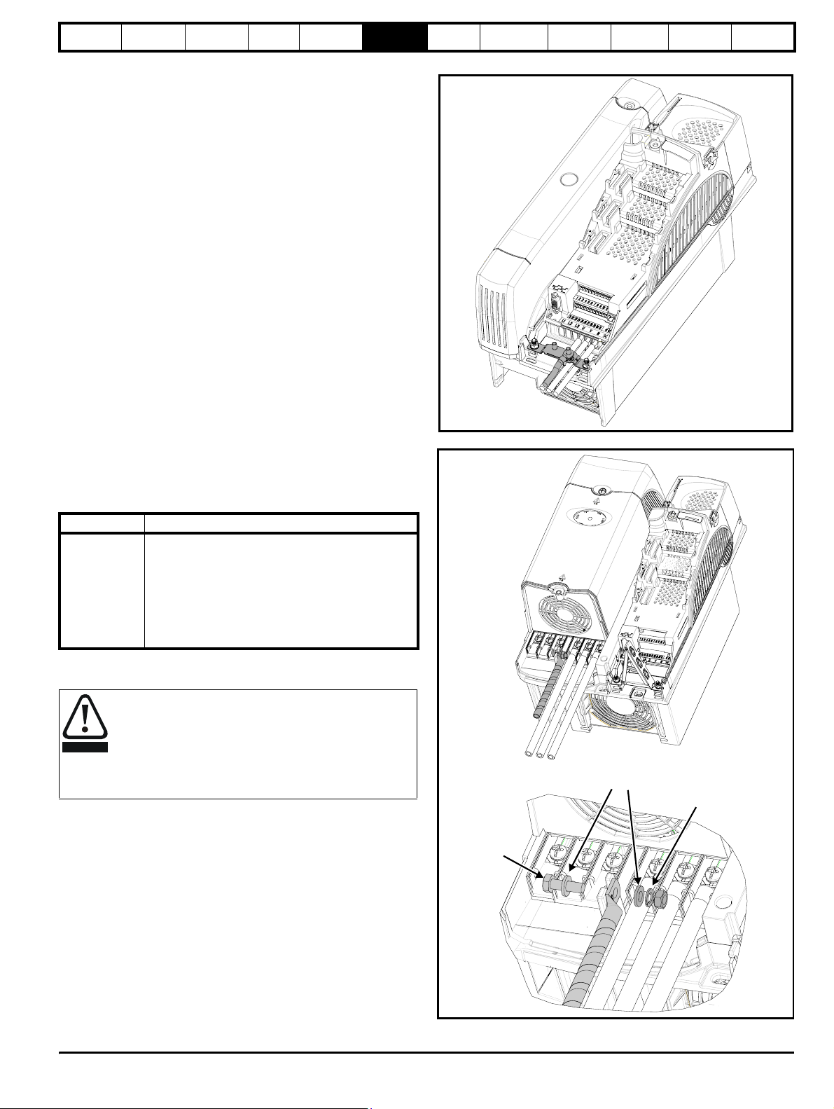
Safety
Information
Introduction
Product
information
System
design
Mechanical
installation
Electrical
installation
6.1.2 Ground connections
Size 1
On a Unidrive SP size 1, the supply and motor ground connections are
made using the studs located either side of the drive near the plug-in
power connector. Refer to Figure 6-1 on page 66.
Size 2
On a Unidrive SP size 2, the supply and motor ground connections are
made using the grounding bridge that locates at the bottom of the drive.
See Figure 6-8 for details.
Size 3
On a Unidrive SP size 3, the supply and motor ground connections are
made using an M6 nut and bolt that locates in the fork protruding from
the heatsink between the AC supply and motor output terminals. See
Figure 6-9 for details.
Size 4, 5, 6, SPMA and SPMD
On a Unidrive SP size 4, 5, 6, SPMA and SPMD the supply and motor
ground connections are made using an M10 bolt at the top (supply) and
bottom (motor) of the drive. See Figure 6-10.
The supply ground and motor ground connections to the drive are
connected internally by a copper conductor with a cross-sectional area
given below:
Size 4: 19.2mm
Size 5: 60mm
Size 6: 75mm
SPMA: 75mm
SPMD: 120mm
This connection is sufficient to provide the ground (equipotential
bonding) connection for the motor circuit under the following conditions:
Table 6-1 Cables and standards
Standard Conditions
IEC 60204-1 &
EN 60204-1
If the necessary conditions are not met, an additional ground connection
must be provided to link the motor circuit ground and the supply ground.
2
(0.03in2, or slightly bigger than 6 AWG)
2
(0.09in2, or slightly bigger than 1 AWG)
2
(0.12in2, or slightly bigger than 2/0 AWG)
2
(0.12in2, or slightly bigger than 2/0 AWG)
2
(0.18in2, or slightly bigger than 2 AWG)
Supply phase conductors having cross-sectional area
not exceeding:
Size 4: 38.4mm
Size 5: 120mm
Size 6: 150mm
SPMA: 150mm
SPMD: 240mm
2
2
2
2
2
Getting
started
Optimisation Parameters
Te ch n ic a l
data
Component
sizing
Figure 6-8 Unidrive SP size 2 ground connections
Figure 6-9 Unidrive SP size 3 ground connections
Diagnostics
The ground loop impedance must conform to the
requirements of local safety regulations.
The drive must be grounded by a connection capable of
WARNING
carrying the prospective fault current until the protective
device (fuse, etc.) disconnects the AC supply.
The ground connections must be inspected and tested at
appropriate intervals.
Plain washers
Spring washer
M6 bolt
Unidr ive SP Re gen Inst allatio n Guide 73
Issue Number: 2 www.controltechniques.com
Page 74
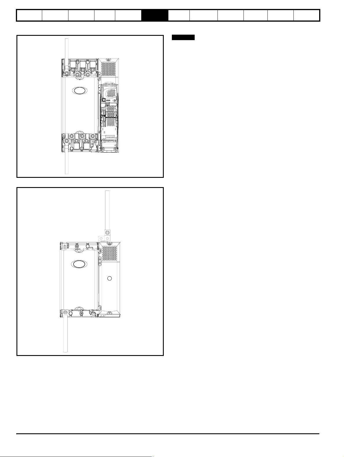
Safety
Information
Figure 6-10 Unidrive SP size 4, 5, 6, SPMA and SPMD ground
Introduction
connections
Product
information
System
design
Mechanical
installation
Electrical
installation
Supply
ground
Motor
ground
Figure 6-11 Unidrive SPMC/U ground connections
Supply
ground
Getting
started
Optimisation Parameters
Te ch ni ca l
data
Component
sizing
Diagnostics
6.2 AC supplies
NOTE
Drives rated for supply voltages up to 690V are suitable for use with
supply types with neutral or centre grounding i.e. TN-S, TN-C-S, TT
The following supplies are not permitted with Unidrive SP Regen
1. Corner grounded supplies (grounded Delta)
2. Ungrounded supplies (IT) > 575V
6.2.1 Supply types
Drives are suitable for use on supplies of installation category III and
lower, according to IEC60664-1. This means they may be connected
permanently to the supply at its origin in a building, but for outdoor
installation additional over-voltage suppression (transient voltage surge
suppression) must be provided to reduce category IV to category III.
6.2.2 Dedicated supplies
The nature of the mains supply has an important effect on the EMC
arrangements. For a dedicated supply, i.e. one which has no other
electrical equipment fed from the secondary of its distribution
transformer, normally neither an EMC filter or a switching frequency filter
are required. Refer to section 4.3.1 Omitting the switching frequency
filter on page 40.
6.2.3 Other supplies
Wherever other equipment shares the same low voltage supply, i.e.
400Vac, careful consideration must be given to the likely need for both
switching frequency and EMC filters, as explained in section
6.5.11 Switching frequency emission and section 6.5.12 Conducted RF
emission .
6.2.4 Supply voltage notching
Because of the use of input inductors and an active rectifier the drive
causes no notching - but see section 6.5.11 Switching frequency
emission for advice on switching frequency emission.
6.2.5 Supply harmonics
When operated from a balanced sinusoidal three-phase supply, the
regenerative Unidrive SP generates minimal harmonic current.
Imbalance between phase voltages will cause the drive to generate
some harmonic current. Existing voltage harmonics on the power
system will cause some harmonic current to flow from the supply into the
drive. Note that this latter effect is not an emission, but it may be difficult
to distinguish between incoming and outgoing harmonic current in a site
measurement unless accurate phase angle data is available for the
harmonics. No general rule can be given for these effects, but the
generated harmonic current levels will always be small compared with
those caused by a conventional drive with rectifier input.
N
Motor
ground
74 Unidrive SP Regen Installation Guide
www.controltechniques.com Issue Number: 2
Page 75
Safety
Information
Introduction
Product
information
System
design
Mechanical
installation
Electrical
installation
6.3 Cable and fuse ratings
The input current is affected by the supply voltage and impedance.
Typical input current
The values of typical input current are given to aid calculations for power
flow and power loss.
The values of typical input current are stated for a balanced supply.
Maximum continuous input current
The values of maximum continuous input current are given to aid the
selection of cables and fuses. These values are stated for the worst case
condition with the unusual combination of stiff supply with bad balance.
The value stated for the maximum continuous input current would only
be seen in one of the input phases. The current in the other two phases
would be significantly lower.
The values of maximum input current are stated for a supply with a 2%
negative phase-sequence imbalance and rated at the maximum supply
fault current given in Table 6-2 to Table 6-2.
Tab le 6-2
Model
SP1201 5.2 10 1.0 10 18
SP1202 6.8 10 1.0 10 16
SP1203 9.6 12 1.0 12 14
SP1204 11 12 1.0 12 14
SP2201 15.5 20 2.5 20 14
SP2202 22 25 4.0 25 10
SP2203 28 32 6.0 32 8
SP3201 42 50 16 50 16
SP3202 54 63 25 63 25
SP1405 8.8 12 1.0 15 14
SP1406 11 16 1.5 15 14
SP2401 15.3 20 2.5 20 14
SP2402 21 25 4.0 25 10
SP2403 29 32 6.0 30 8
SP2404 29 32 6.0 30 8
SP3401 35 40 10 40 6
SP3402 43 50 16 45 6
SP3403 56 63 25 60 4
SP3501 5.4 8 1.0 8 18
SP3502 6.1 8 1.0 8 16
SP3503 8.4 12 1.0 12 14
SP3504 11 12 1.0 12 14
SP3505 16 20 2.5 20 14
SP3506 22 25 4.0 25 10
SP3507 27 32 6.0 32 8
Size 1 to 3 input current, fuse and cable size ratings
European USA
Maximum
A
Cable size
EN60204
Input
2
mm
Fuse
rating
IEC gG
A
UL508C
continuous
input
current
A
Fuse
rating
IEC gG
Cable
size
Input
AWG
Getting
started
Optimisation Parameters
Te ch n ic a l
data
Component
sizing
Diagnostics
Unidr ive SP Re gen Inst allatio n Guide 75
Issue Number: 2 www.controltechniques.com
Page 76
Safety
Information
Tab le 6-3
Model
Introduction
Size 4, 5, 6 and the SPM input current, fuse and cable size ratings (universal)
Maximum
continuous
input
current
A
Product
information
System
design
Mechanical
installation
IEC class gR OR
American Ferraz HSJ
IEC classgRNorth American
Ferraz HSJ
North
Electrical
installation
HRC AND
HRC IEC class gG
UL class J
Getting
started
Optimisation Parameters
Semi-conductor Cable size
Semi- Conductor
IEC class aR
Te ch ni ca l
data
2
mm
AWG
SP4201 68 100 90 90 160 25 3
SP4202 80 100 100 100 160 35 3
SP4203 104 125 125 125 200 70 1
SP5201 130 200 175 160 200 95 210
SP5202 154 250 225 200 250 120 410
SP4401 68 80 80 80 160 25 3
SP4402 83 110 110 100 200 35 2
SP4403 104 125 125 125 200 70 1
SP5401 138 200 175 160 200 95 2/0
SP5402 168 250 225 200 250 120 4/0
SP6401 205 250 250 250 315 2 x 70 2 x 2/0
SP6402 236 315 300 300 350 2 x 120 2 x 4/0
SPMA1401 205 315 300 250 315 2 x 70 2 x 2/0
SPMA1402 246 315 300 300 350 2 x 120 2 x 4/0
SPMD1201 192
SPMD1202 248
SPMD1203 312
Refer to SPMC
SPMD1204 350
SPMD1401 205
SPMD1402 246
SPMD1403 290
Refer to SPMC
SPMD1404 350
SP4601 22 63 60 32 125 4 10
SP4602 27 63 60 40 125 6 8
SP4603 36 63 60 50 125 10 8
SP4604 43 63 60 50 125 16 6
SP4605 52 63 60 63 125 16 6
SP4606 62 80 60 63 125 25 4
SP5601 84 125 100 90 160 35 2
SP5602 99 125 100 125 160 50 1
SP6601 125 160 175 150 315 2 x 50 2 x 1
SP6602 144 160 175 160 315 2 x 50 2 x 1
SPMA1601 125 200 200 200 200 2 x 50 2 x 1
SPMA1602 144 200 200 200 200 2 x 50 2 x 1
SPMD1601 125
SPMD1602 144
SPMD1603 168
Refer to SPMC
SPMD1604 192
Component
sizing
Diagnostics
Table 6-4 Unidrive SPMD input current, fuse and cabling ratings
Model
Typical DC
Input current
A
Maximum DC
Input current
A
Maximum DC
Input voltage
Vdc
DC fuse
IEC class aR
A
DC Cable size
2
mm
AWG
SPMD1401 222 343 800 400 2 x 70 2 x 2/0
SPMD1402 268 400 800 560 2 x 95 2 x 4/0
SPMD1403 314 457 800 560 2 x 120 2 x 4/0
SPMD1404 379 552 800 560 2 x 120 2 x 4/0
SPMD1601 135 191 1150 250 2 x 95 2 x 4/0
SPMD1602 157 240 1150 315 2 x 120 2 x 4/0
SPMD1603 184 275 1150 350 2 x 120 2 x 4/0
SPMD1604 209 323 1150 400 2 x 120 2 x 4/0
76 Unidrive SP Regen Installation Guide
www.controltechniques.com Issue Number: 2
Page 77
Safety
Information
Introduction
Product
information
System
design
Mechanical
installation
Electrical
installation
Getting
started
Optimisation Parameters
Te ch n ic a l
data
Table 6-5 SPMC / U input current, fuse and cable ratings
Cable sizes
AWG
mm
2
AWG
Model
Typical
input
current
A
Maximum
input
current
A
Typical
DC
current
Adc
Semi-conductor fuse
in series with HRC fuse
HRC IEC
class gG UL
class J
Semi-
conductor
IEC class aR
AC input DC output
2
mm
SPMC1402 339 344 379 540 400 2 x 120 2 x 4/0 2 x 120 2 x 4/0
SPMC2402 2 x 308 2 x 312 2 x 345 450 400 2 x 120 2 x 4/0 2 x 120 2 x 4/0
SPMU1401 207 210 222 250 315 2 x 70 2 x 2/0 2 x 70 2 x 2/0
SPMU1402 339 344 379 540 400 2 x 120 2 x 4/0 2 x 120 2 x 4/0
SPMU2402 2 x 339 609 2 x 379 450 400 2 x 120 2 x 4/0 2 x 120 2 x 4/0
SPMC1601 192 195 209 250 250 2 x 70 2 x 2/0 2 x 120 2 x 4/0
SPMC2601 2 x 170 2 x 173 2 x 185 250 250 2 x 70 2 x 2/0 2 x 120 2 x 4/0
SPMU1601 192 195 209 250 250 2 x 70 2 x 2/0 2 x 120 2 x 4/0
SPMU2601 2 x 170 2 x 173 2 x 185 250 250 2 x 70 2 x 2/0 2 x 120 2 x 4/0
The recommended cable sizes above are only a guide. Refer to local
wiring regulations for the correct size of cables. In some cases a larger
cable is required to avoid excessive voltage drop.
NOTE
N
The recommended cable sizes above are only a guide. The mounting
and grouping of cables affects their current-carrying capacity, in some
cases smaller cables may be acceptable but in other cases a larger
cable is required to avoid excessive temperature or voltage drop. Refer
3. B - detects AC, pulsating DC and smooth DC fault currents
• Type AC should never be used with drives.
• Type A can only be used with single phase drives
• Type B must be used with three phase drives
Only type B ELCB / RCD are suitable for use with 3-phase
inverter drives.
WARNING
to local wiring regulations for the correct size of cables.
6.4 EMC (Electromagnetic compatibility)
Fuses
The AC supply to the drive must be fitted with suitable
protection against overload and short-circuits. Failure to
WARNING
observe this requirement will cause risk of fire.
A fuse or other protection must be included in all live connections to the
AC supply.
An MCB (miniature circuit breaker) or MCCB (moulded-case circuitbreaker) with type C may be used in place of fuses on Unidrive SP sizes
1 to 3 under the following conditions:
• The fault-clearing capacity must be sufficient for the installation
• For frame sizes 2 and 3, the drive must be mounted in an enclosure
which meets the requirements for a fire enclosure.
Fuse types
The fuse voltage rating must be suitable for the drive supply voltage.
Ground connections
The drive must be connected to the system ground of the AC supply.
The ground wiring must conform to local regulations and codes of
practice.
6.3.1 Main AC supply contactor
The recommended AC supply contactor type for sizes 1 to 6 is AC1.
6.3.2 Motor winding voltage
Refer to the guidelines given in section 4.7.2 of the Unidrive SP User
Guide. The DC bus voltage in a regen system with a 400V supply is
usually 700V, which corresponds to an AC supply voltage of 519V.
Unless the motor cable is less than 10m long it is recommended that
either an inverter-grade motor should be used or else output chokes
should be fitted to protect the motor from the effect of the fast-rising
output voltage pulses.
The requirements for EMC are divided into three levels in the following
three sections:
Section 6.5.2, General requirements for all applications, to ensure
reliable operation of the drive and minimise the risk of disturbing nearby
equipment. The immunity standards specified in section 11 will be met,
but no specific emission standards. Note also the special requirements
given in Surge immunity of control circuits - long cables and connections
outside a building in the EMC section of the Unidrive SP User Guide for
increased surge immunity of control circuits where control wiring is
extended.
Section 6.5.3, Requirements for meeting the EMC standard for
power drive systems, IEC61800-3 (EN61800-3).
Section 6.5.4, Requirements for meeting the generic emission
standards for the industrial environment, IEC61000-6-4, EN61000-6-4,
EN50081-2.
The recommendations of section 6.5.2 will usually be sufficient to avoid
causing disturbance to adjacent equipment of industrial quality. If
particularly sensitive equipment is to be used nearby, or in a nonindustrial environment, then the recommendations of section 6.5.3 or
section 6.5.4 should be followed to give reduced radio-frequency
emission.
In order to ensure the installation meets the various emission standards
described in:
• The EMC data sheet available from the supplier of the drive
• The Declaration of Conformity at the front of this manual
• Chapter 10 Technical data
...the correct external EMC filter must be used and all of the guidelines in
section 6.5.2 General requirements for EMC and section
6.5.4 Compliance with generic emission standards must be followed.
Component
sizing
Diagnostics
6.3.3 Use of residual current device (RCD)
There are three common types of ELCB / RCD:
1. AC - detects AC fault currents
2. A - detects AC and pulsating DC fault currents (provided the DC
current reaches zero at least once every half cycle)
Unidr ive SP Re gen Inst allatio n Guide 77
Issue Number: 2 www.controltechniques.com
Page 78

Safety
Information
Introduction
Product
information
System
design
Mechanical
installation
Electrical
installation
Getting
started
Optimisation Parameters
Te ch ni ca l
data
Component
sizing
Diagnostics
Table 6-6 Unidrive SP / EMC filter cross reference
Drive
Schaffner Epcos
CT part no. CT part no.
SP1201 to SP1202 4200-6118 4200-6121
SP1203 to SP1204 4200-6119 4200-6120
SP2201 to SP2203 4200-6210 4200-6211
SP3201 to SP3202 4200-6307 4200-6306
SP4201 to SP4203 4200-6406 4200-6405
SP5201 to SP5202 4200-6503 4200-6501
SPMD1201 to SPMD1204 4200-6315 4200-6313
SP1401 to SP1404 4200-6118 4200-6121
SP1405 to SP1406 4200-6119 4200-6120
SP2401 to SP2404 4200-6210 4200-6211
SP3401 to SP3403 4200-6305 4200-6306
SP4401 to SP4403 4200-6406 4200-6405
SP5401 to SP5402 4200-6503 4200-6501
SP6401 to SP6402 4200-6603 4200-6601
SPMA1401 to SPMA1402 4200-6603 4200-6601
SPMD1401 to SPMD1404 4200-6315 4200-6313
SP3501 to SP3507 4200-6309 4200-6308
SP4601 to SP4606 4200-6408 4200-6407
SP5601 to SP5602 4200-6504 4200-6502
SP6601 to SP6602 4200-6604 4200-6602
SPMA1601 to SPMA1602 4200-6604 4200-6602
SPMD1601 to SPMD1604 4200-6316 4200-6314
6.5.1 Removal of internal EMC filter
The internal EMC filter must be removed from the drive.
CAUTION
Figure 6-12 Removal of internal EMC filter (size 1 to 3)
1
2
3
4
Loosen / remove screws as shown (1) and (2).
Remove filter (3), and ensure the screws are replaced and re-tightened (4).
Figure 6-13 Removal of internal EMC filter (size 4 to 6)
1
2
6.5 External EMC filter
In order to provide our customers with a degree of flexibility, external
EMC filters have been sourced from two manufacturers: Schaffner and
Epcos. The external EMC Filter ratings and dimensions information are
available in the Unidrive SP User Guide.
For currents exceeding 300A up to 2500A, suitable filters are also
available from both Epcos and Schaffner as detailed.
• Epcos B84143-B250-5xx (range up to 2500A)
• Schaffner FN3359-300-99 (range up to 2400A)
These filters may not give strict conformity with EN6000-6-4 but in
conjunction with EMC installation guidelines they will reduce emissions
to sufficiently low levels to minimise the risk of disturbance.
When a EMC filter is used, the switching frequency filter
detailed must also be used. Failure to observe this may result
in the EMC filter becoming ineffective and being damaged.
CAUTION
WARNING
CAUTION
Refer to section 6.4 EMC (Electromagnetic compatibility) on
page 77.
When an EMC filter is used, a permanent fixed ground
connection must be provided which does not pass through a
connector or flexible power cord. This includes the internal
EMC filter.
The installer of the drive is responsible for ensuring
compliance with the EMC regulations that apply where the
drive is to be used.
Loosen screws (1). Remove EMC filter in the direction shown (2).
78 Unidrive SP Regen Installation Guide
www.controltechniques.com Issue Number: 2
Page 79
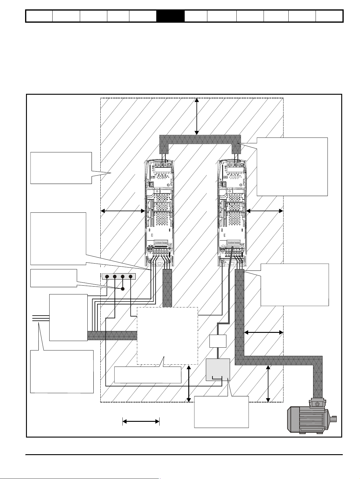
Safety
Information
Introduction
Product
information
System
design
Mechanical
installation
Electrical
installation
Getting
started
6.5.2 General requirements for EMC
Ground (earth) connections
The grounding arrangements should be in accordance with Figure 6-14,
which shows both drives mounted on a back-plate with or without an
additional enclosure.
Figure 6-14 shows how to manage EMC when using a shielded motor
cable, and indicates the clearances which should be observed around
the drive and related ‘noisy’ power cables by all sensitive control signals
/ equipment.
Figure 6-14 General EMC enclosure layout showing earth / ground connections
±
DC bus connections
Do not place sensitive
(unscreened) signal circuits
in a zone extending
300mm (12”) all around the
drive, motor cable, input
cable from EMC filter
Regen drive
Optimisation Parameters
Motoring drive
Te ch n ic a l
data
The DC connection between the
Regen and motoring drive carries
common mode high frequency
voltage comparable with the
output voltage from a standard
drive.
Screened cable should be used
with the screen connection
connected to a single power
ground busbar or low impedance
ground terminal inside the cubicle.
Component
sizing
Diagnostics
The voltage present in the
wiring between the Regen
drive and regen inductor
is a source of radio
emission. These cables
should be kept as short as
possible. (I.e. The regen
inductor mounted as
close as possible to the
Regen drive.)
Metal backplate
safety bonded to
power ground busbar
EMC filter
The incoming supply ground,
PE, should be connected to a
single power ground bus bar
or low impedance ground
terminal inside the cubicle.
This should be used as a
common 'clean' ground for all
components inside the cubicle.
Grounding
bar
Regen
components
Screen and ground connections
should be followed as shown in
.Electrical Installation
Signal
cables
External
controller
PE
0V
Use four core cable to
connect the motor to the drive.
The ground conductor in the
motor cable must be connected
directly to the ground terminal of
the drive and motor.
It must not be connected directly
to the power ground busbar.
If the control circuit 0V
is to be grounded, this
300mm
(12in)
should be done at the
system controller only to
avoid injecting noise
currents into the 0V circuit
Unidr ive SP Re gen Inst allatio n Guide 79
Issue Number: 2 www.controltechniques.com
Page 80
Safety
Information
Introduction
Product
information
System
design
Mechanical
installation
Electrical
installation
Getting
started
Optimisation Parameters
Te ch ni ca l
data
Component
sizing
Diagnostics
6.5.3 Compliance with EN61800-3 (standard for Power Drive Systems)
Meeting the requirements of this standard depends on the environment
that the drive is intended to operate in, as follows:
Operation in the first environment
Observe the guidelines given in section 6.5.4 Compliance with generic
emission standards on page 80. An external EMC filter will always be
required.
This is a product of the restricted distribution class according
to IEC61800-3
In a domestic environment this product may cause radio
CAUTION
interference in which case the user may be required to take
adequate measures.
Operation in the second environment
In all cases a shielded motor cable must be used, and an EMC filter is
required for all Unidrive SPs with a rated input current of less than 100A.
Size 1
Where a filter is required, follow the guidelines in section 6.5.2 General
requirements for EMC on page 79.
For cable lengths up to 10m compliance can be maintained by fitting a
ferrite ring, part no. 4200-0000, 4200-0001 or 4200-3608, to the drive
output. Feed the motor cables (U,V,W) through the ring once.
Size 2 and 3
Where a filter is required, follow the guidelines in section 6.5.2 General
requirements for EMC on page 79.
The second environment typically includes an industrial lowvoltage power supply network which does not supply
buildings used for domestic purposes. Operating the drive in
this environment without an external EMC filter may cause
CAUTION
interference to nearby electronic equipment whose sensitivity
has not been appreciated. The user must take remedial
measures if this situation arises. If the consequences of
unexpected disturbances are severe, it is recommended that
the guidelines in section 6.5.4 Compliance with generic
emission standards be adhered to.
Refer to section 6.4 EMC (Electromagnetic compatibility) on page 77 for
further information on compliance with EMC standards and definitions of
environments.
Detailed instructions and EMC information are given in the Unidrive SP
EMC Data Sheet which is available from the supplier of the drive.
6.5.4 Compliance with generic emission standards
Use the recommended filter and shielded motor cable. Observe the
layout rules given in the current Unidrive SP User Guide.
6.5.5 Immunity
The immunity of the individual drive modules is not affected by operation
in the regenerative mode. See drive EMC data sheets for further
information.
This guide recommends the use of varistors between the incoming AC
supply lines. These are strongly recommended to protect the drive from
surges caused by lightning activity and/or mains supply switching
operations.
Since the regenerative input stage must remain synchronised to the
supply, there is a limit to the permitted rate of change of supply
frequency. If rates of change exceeding 100Hz/s are expected then C.T.
Technical Support should be consulted. This would only arise under
exceptional circumstances e.g. where the power system is supplied from
an individual generator.
6.5.6 Emission
Emission occurs over a wide range of frequencies. The effects are
divided into three main categories:
• Low frequency effects, such as supply harmonics and notching
• High frequency emission below 30MHz where emission is
predominantly by conduction
• High frequency emission above 30MHz where emission is
predominantly by radiation
6.5.7 Dedicated supplies
The nature of the mains supply has an important effect on the EMC
arrangements. For a dedicated supply, i.e. one which has no other
electrical equipment fed from the secondary of its distribution
transformer, normally neither an EMC filter or a switching frequency filter
are required. Refer to section 4.3.1 Omitting the switching frequency
filter on page 40.
6.5.8 Other supplies
Wherever other equipment shares the same low voltage supply, i.e.
400Vac, careful consideration must be given to the likely need for both
switching frequency and EMC filters, as explained in section
6.5.11 Switching frequency emission and section 6.5.12 Conducted RF
emission .
6.5.9 Supply voltage notching
Because of the use of input inductors and an active rectifier the drive
causes no notching - but see section 6.5.11 Switching frequency
emission for advice on switching frequency emission.
6.5.10 Supply harmonics
When operated from a balanced sinusoidal three-phase supply, the
regenerative Unidrive SP generates minimal harmonic current.
Imbalance between phase voltages will cause the drive to generate
some harmonic current. Existing voltage harmonics on the power
system will cause some harmonic current to flow from the supply into the
drive. Note that this latter effect is not an emission, but it may be difficult
to distinguish between incoming and outgoing harmonic current in a site
measurement unless accurate phase angle data is available for the
harmonics. No general rule can be given for these effects, but the
generated harmonic current levels will always be small compared with
those caused by a conventional drive with rectifier input.
6.5.11 Switching frequency emission
The Regen drive uses a PWM technique to generate a sinusoidal input
voltage phase-locked to the mains supply. The input current therefore
contains no harmonics of the supply unless the supply itself contains
harmonics or is unbalanced. It does however contain current at the
switching frequency and its harmonics, modulated by the supply
frequency. For example, with a 3kHz switching frequency and 50Hz
supply frequency there is current at 2.90, 3.10, 5.95, 6.05kHz etc. The
switching frequency is not related to that of the supply, so the emission
will not be a true harmonic - it is sometimes referred to as an
“interharmonic”. The possible effect of this current is similar to that of a
high-order harmonic, and it spreads through the power system in a
manner depending on the associated impedances. The internal
impedance of the Regen drive is dominated by the series inductors at
the input. The voltage produced at switching frequency at the supply
point is therefore determined by the potential divider action of the series
inductors and the supply impedance; Supply assessment on page 40
gives guidelines to help in assessing whether a switching-frequency filter
is required. In case of doubt, unless the drive operates from a dedicated
supply not shared with other loads, it is strongly recommended that the
filter be fitted.
Failure to fit a switching frequency filter may result in damage
to other equipment, e.g. fluorescent light fittings, power factor
correction capacitors and EMC filters.
CAUTION
80 Unidrive SP Regen Installation Guide
www.controltechniques.com Issue Number: 2
Page 81
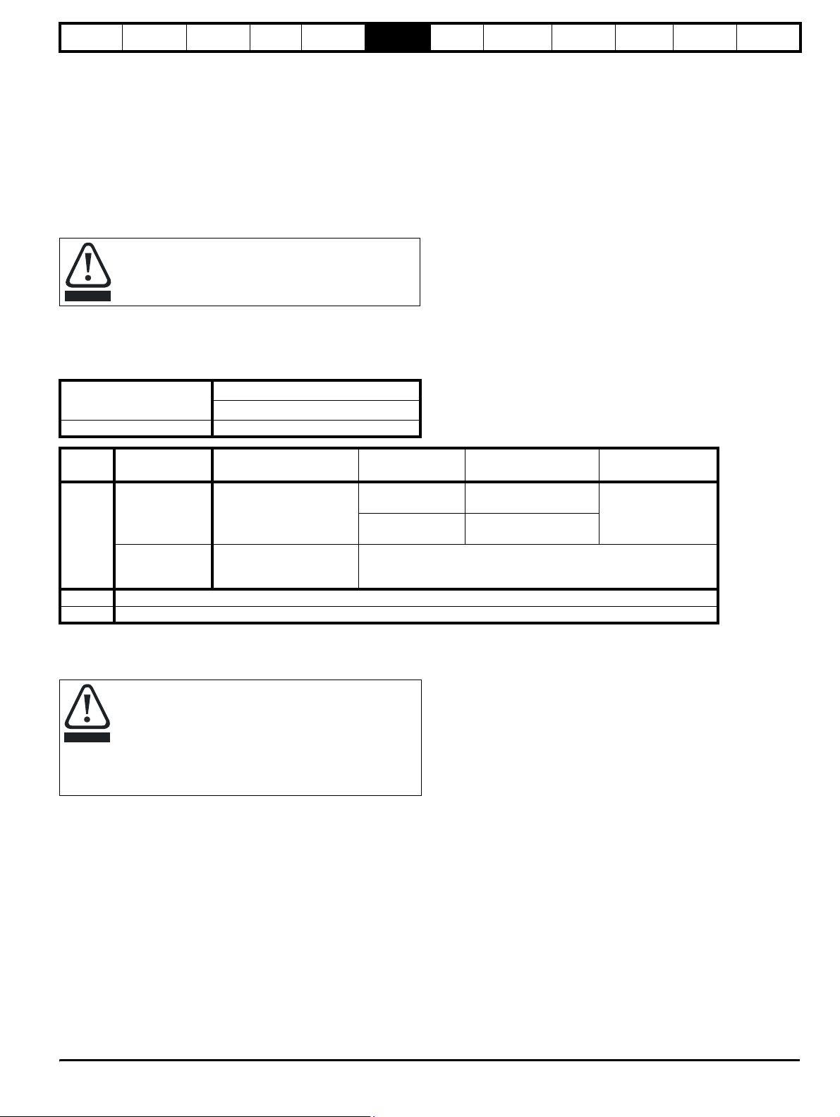
Safety
Information
Introduction
Product
information
System
design
Mechanical
installation
Electrical
installation
6.5.12 Conducted RF emission
Radio frequency emission in the frequency range from 150kHz to
30MHz is mainly conducted out of the equipment through electrical
wiring. It is essential for compliance with all emission standards, except
for IEC61800-3 second environment, that the recommended EMC filter
and a shielded (screened) motor cable are used. Most types of cable
can be used provided it has an overall screen. For example, the screen
formed by the armouring of steel wired armoured cable is acceptable.
The capacitance of the cable forms a load on the drive and should be
kept to a minimum. The same considerations apply to any cables
connecting the DC bus between drives, except that short direct wiring
within the same enclosure need not be screened.
When an EMC filter is used the switching frequency filter
discussed above must also be used. Failure to observe this
may result in the EMC filter becoming ineffective and being
CAUTION
When used with the recommended filters, the Regen drive system
complies with the requirements for conducted emission in the following
standards:
Table 6-7 Requirements for conducted emission
damaged.
Motor cable length (m)
0 to 100 I
Switching frequency (kHz)
3
Getting
started
Optimisation Parameters
Te ch n ic a l
data
Component
sizing
Diagnostics
Key to
table
I
1
2
Standard Description
EN50081-2
Generic emission standard
for the industrial
environment
EN61800-3
IEC1800-3
Product standard for
adjustable speed power
drive systems
The first environment is one where the low voltage supply network also supplies domestic premises
Restricted distribution means that drives are available only to installers with EMC competence
Frequency
range
0.15 to 0.5MHz
0.5 to 30MHz
Requirements for the first environment
Requirements for the second environment: unrestricted distribution
For installation in the “second environment”, i.e. where the low voltage
supply network does not supply domestic premises, no filter is required
in order to meet IEC61800-3 (EN61800-3):1996.
Operation without a filter is a practical cost-effective
possibility in an industrial installation where existing levels of
electrical noise are likely to be high, and any electronic
CAUTION
equipment in operation has been designed for such an
environment. There is some risk of disturbance to other
equipment, and in this case the user and supplier of the drive
system must jointly take responsibility for correcting any
problem which occurs.
Limits Application
79dBµV quasi peak
66dBµV average
73dBµV quasi peak
60dBµV average
1
: restricted distribution2
AC supply lines
Unidr ive SP Re gen Inst allatio n Guide 81
Issue Number: 2 www.controltechniques.com
Page 82
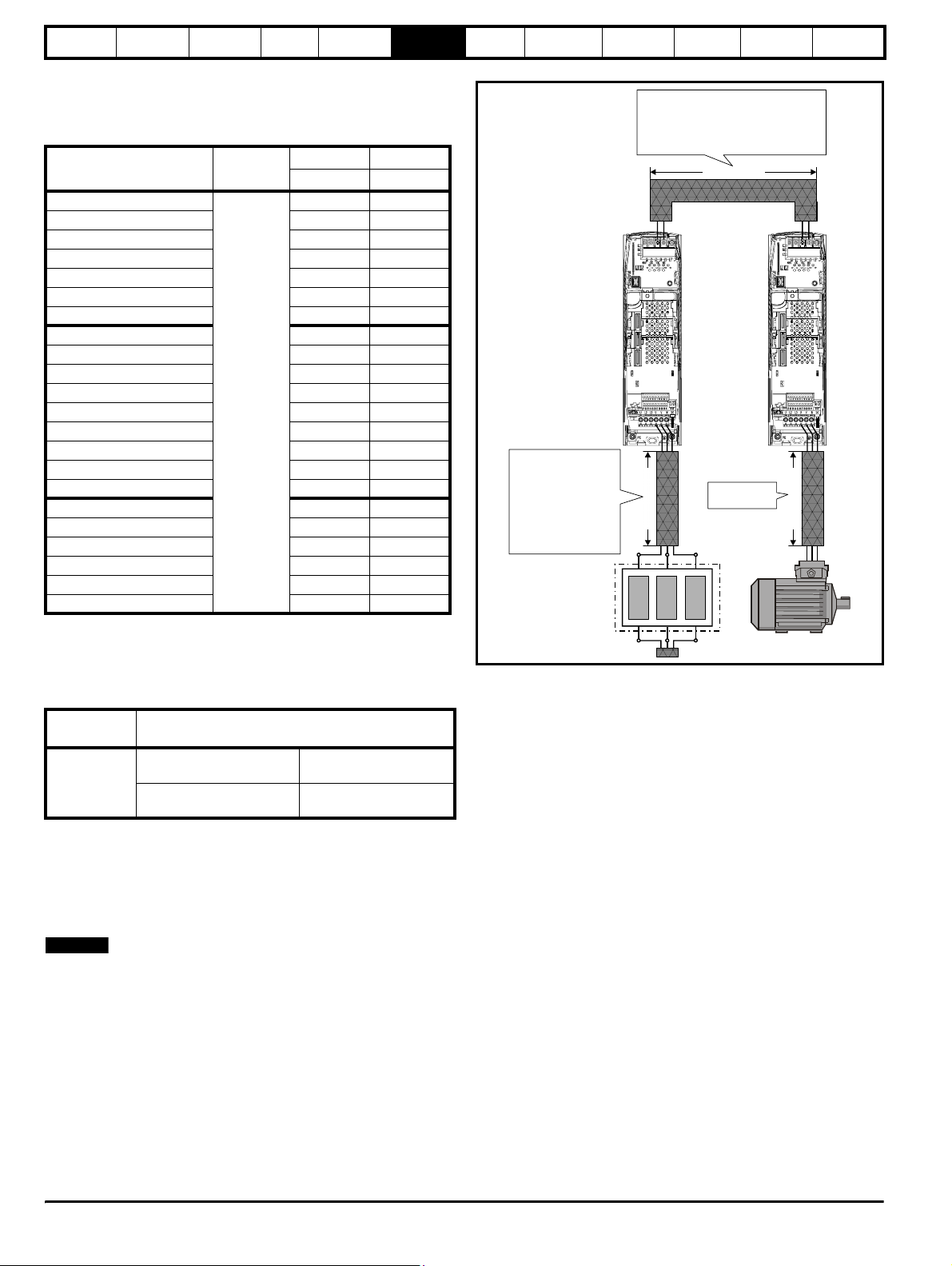
Safety
r
Information
Introduction
Product
information
System
design
Mechanical
installation
Electrical
installation
Recommended EMC filters
These are the same filters as recommended for standard (nonregenerative) operation:
Table 6-8 Recommended filters
Drive
Motor cable
length m
SP1201 to SP1202
SP1203 to SP1204 4200-6119 4200-6120
SP2201 to SP2203 4200-6210 4200-6211
SP3201 to SP3202 4200-6307 4200-6306
SP4201 to SP4203 4200-6406 4200-6405
SP5201 to SP5202 4200-6503 4200-6501
SPMD1201 to SPMD1204 4200-6315 4200-6313
SP1401 to SP1404 4200-6118 4200-6121
SP1405 to SP1406 4200-6119 4200-6120
SP2401 to SP2404 4200-6210 4200-6211
SP3401 to SP3403 4200-6305 4200-6306
SP4401 to SP4403 4200-6406 4200-6405
100
SP5401 to SP5402 4200-6503 4200-6501
SP6401 to SP6402 4200-6603 4200-6601
SPMA1401 to SPMA1402 4200-6603 4200-6601
SPMD1401 to SPMD1404 4200-6315 4200-6313
SP3501 to SP3507 4200-6309 4200-6308
SP4601 to SP4606 4200-6408 4200-6407
SP5601 to SP5602 4200-6504 4200-6502
SP6601 to SP6602 4200-6604 4200-6602
SPMA1601 to SPMA1602 4200-6604 4200-6602
SPMD1601 to SPMD1604 4200-6316 4200-6314
Schaffner Epcos
CT part no. CT part no.
4200-6118 4200-6121
Getting
started
Optimisation Parameters
Te ch ni ca l
data
Figure 6-15 Power cable considerations
The DC connection between the Regen and
motoring drive carries common mode high
frequency voltage comparable with the output
voltage from a standard drive. Clearances and
recommendations for standard power cables
must be applied here.
Cable length B
±
DC bus connections
Regen drive
The voltage present in the
wiring between the Regen
drive and regen inductor
is a source of radio
emission. These cables
should be kept as short as
possible. (I.e. The regen
inductor mounted as
close as possible to the
Regen drive.)
Cable length A
Standard wiring
practices apply.
Regen inductor Moto
Component
sizing
Motoring drive
Cable length C
Diagnostics
Related product standards
The conducted emission levels specified in EN50081-2 are equivalent to
the levels required by the following product specific standards:
Table 6-9 Conducted emission from 150kHz to 30MHz
Generic
standard
EN61000-6-4
EN55011 Class A Group 1
CISPR 11 Class A Group 1
EN55022 Class A
CISPR 22 Class A
Product standard
Industrial, scientific and
medical equipment
Information technology
equipment
6.5.13 Radiated emission
Radio frequency emission in the frequency range from 30MHz to 1GHz
is mainly radiated directly from the equipment and from the wiring in its
immediate vicinity. Operation in regenerative mode does not alter the
radiated emission behaviour, and the EMC data sheet for the individual
Unidrive SPs used should be consulted for further information.
NOTE
N
Theoretically the use of two drives physically close together can cause
an increase in emission level of 3dB compared with a single drive,
although this is usually not observed in practice. All Unidrive SPs have
sufficient margin in respect of the generic standard for the industrial
environment EN61000-6-4 to allow for this increase.
6.5.14 Wiring guidelines
The wiring guidelines provided for the individual drives also apply to
regenerative operation, except that the switching frequency filter must
be interposed between the input drive and the EMC filter. The same
principles apply, the most important aspect being that the input
connections to the EMC filter should be carefully segregated from the
power wiring of the drives which carries a relatively high “noise” voltage.
6.5.15 Main contactors K2 with SPMC
When using an SPMC for the charging of a regen system the main
contactor K2 should be positioned as close as possible to the Regen
drives power terminals.
6.5.16 Multi-drive systems
It is common for regenerative drive systems to be constructed using
numbers of drives with a single input stage, or other more complex
arrangements. It is generally not possible to lay down specific EMC
requirements for such systems, since they are too large for standardised
tests to be carried out. In many cases the environment corresponds to
the “second environment” as described in IEC61800-3, in which case no
specific limit to conducted emission is required. National legislation such
as the European Union EMC Directive does not usually require that
complex installations meet specific standards, but only that they meet
the essential protection requirements, i.e. not to cause or suffer from
electromagnetic interference.
Where the environment is known to include equipment which is sensitive
to electromagnetic disturbance, or the low voltage supply network is
shared with domestic dwellings, then precautions should be taken to
minimise conducted radio frequency emission by the use of a filter at the
system power input.
For currents exceeding 300A up to 2500A suitable filters are available
from the following manufacturers:
Epcos B84143-B250-5xx (range up to 2500A)
Schaffner FN3359-300-99 (range up to 2400A)
These filters may not give strict conformity with EN61000-6-4, but in
conjunction with the relevant EMC installation guidelines they will reduce
emission to sufficiently low levels to minimise the risk of disturbance.
82 Unidrive SP Regen Installation Guide
www.controltechniques.com Issue Number: 2
Page 83
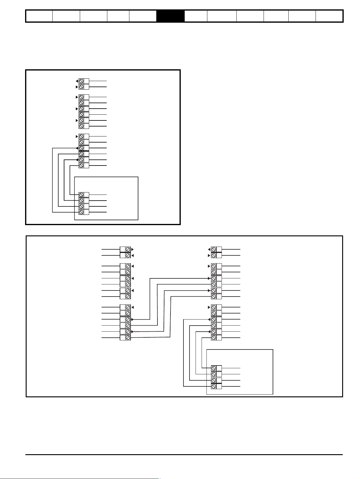
Safety
Information
Introduction
Product
information
System
design
Mechanical
installation
Electrical
installation
6.6 Control connections
6.6.1 Unidrive SPMC control terminals
The following diagram shows the required connections for the SPMC to
T.84 and T.85. Also shown is the status relay which can be utilised if
required.
Figure 6-16 Single rectifier control terminals and descriptions
Single Rectifier
91
90
Status relay
Getting
started
Optimisation Parameters
Te ch n ic a l
data
Component
sizing
Diagnostics
75
74
73
72
71
70
85
84
83
82
81
80
Inverter (master)
60
61
62
63
Fan control
0V common
Status input 0
0V common
Status input 1
0V common
External 24V supply
0V common
Status output 0
0V common
Status output 1
0V common
SPMA / SPMD
0V common
Status 1 input
0V common
Status 0 input
Figure 6-17 Parallel rectifier control terminals and descriptions
Rectifier 1
Status relay
Fan control
0V common
Status input 0
0V common
Status input 1
0V common
91
90
75
74
73
72
71
70
91
90
75
74
73
72
71
70
Rectifier 2
Status relay
Fan control
0V common
Status input 0
0V common
Status input 1
0V common
External 24V supply
0V common
Status output 0
0V common
Status output 1
0V common
85
84
83
82
81
80
85
84
83
82
81
80
Inverter (master)
SPMA / SPMD
60
61
62
63
External 24V supply
0V common
Status output 0
0V common
Status output 1
0V common
0V common
Status 1 input
0V common
Status 0 input
Unidrive SPMC/U external 24V supply requirements
Nominal voltage: 24V
Minimum voltage: 23V
Maximum voltage: 28V
Current drawn: 3A
Minimum start-up voltage: 18V
Recommended power supply: 24V, 100W, 4.5A
Recommended fuse:
4A fast blow (I2t <20A2s)
Unidr ive SP Re gen Inst allatio n Guide 83
Issue Number: 2 www.controltechniques.com
Page 84
Safety
Information
Introduction
Product
information
System
design
Mechanical
installation
Electrical
installation
6.6.2 Unidrive SP control terminals
Table 6-10 The Unidrive SP control connections consist of:
Function Qty Control parameters Terminal No.
Differential analogue
input
Single ended analogue
input
Analogue output 2 Source, mode, scaling, 9,10
Digital input 3 Destination, invert, logic select 27,28,29
Digital input / output 3
Relay 1
Drive enable (Secure
Disable)
+10V User output 1
+24V User output 1 Source, invert 22
0V common 6
+24V External input 1
All analogue terminal functions can be programmed in menu 7.
Available digital terminal functions can be programmed in menu 8.
NOTE
N
The digital I/O at default has been configured to accept external signals
from main and auxiliary contactors to allow the regen mode to function
correctly. Before changing any routing, refer to Menu 8 descriptions.
Destination, offset, offset trim,
1
invert, scaling
Mode, offset, scaling, invert,
2
destination
Not user available, used for
regen configuration
Relay configured for contactor
coil power supply
1
5,6
7,8
24,25,26
41,42
31
4
1, 3, 11, 21,
23, 30
2
Getting
started
Optimisation Parameters
Te ch ni ca l
data
Component
sizing
Diagnostics
The control circuits are isolated from the power circuits in the
drive by basic insulation (single insulation) only. The installer
must ensure that the external control circuits are insulated
WARNING
from human contact by at least one layer of insulation
(supplementary insulation) rated for use at the AC supply
voltage.
If the control circuits are to be connected to other circuits
classified as Safety Extra Low Voltage (SELV) (e.g. to a
personal computer), an additional isolating barrier must be
WARNING
included in order to maintain the SELV classification.
If any of the digital inputs or outputs (including the drive
enable input) are connected in parallel with an inductive load
(i.e. contactor or motor brake) then suitable suppression (i.e.
CAUTION
diode or varistor) should be used on the coil of the load. If no
suppression is used then over voltage spikes can cause
damage to the digital inputs and outputs on the drive.
Ensure the logic sense is correct for the control circuit to be
used. Incorrect logic sense could cause the motor to be
started unexpectedly.
CAUTION
NOTE
Positive logic is the default state for Unidrive SP.
N
The Secure Disable / drive enable terminal is a positive logic input only.
It is not affected by the setting of Pr 8.29 Positive logic select.
NOTE
N
The common 0V from analogue signals should, wherever possible, not
be connected to the same 0V terminal as the common 0V from digital
signals. Terminals 3 and 11 should be used for connecting the 0V
common of analogue signals and terminals 21, 23 and 30 for digital
signals. This is to prevent small voltage drops in the terminal
connections causing inaccuracies in the analogue signals.
84 Unidrive SP Regen Installation Guide
www.controltechniques.com Issue Number: 2
Page 85
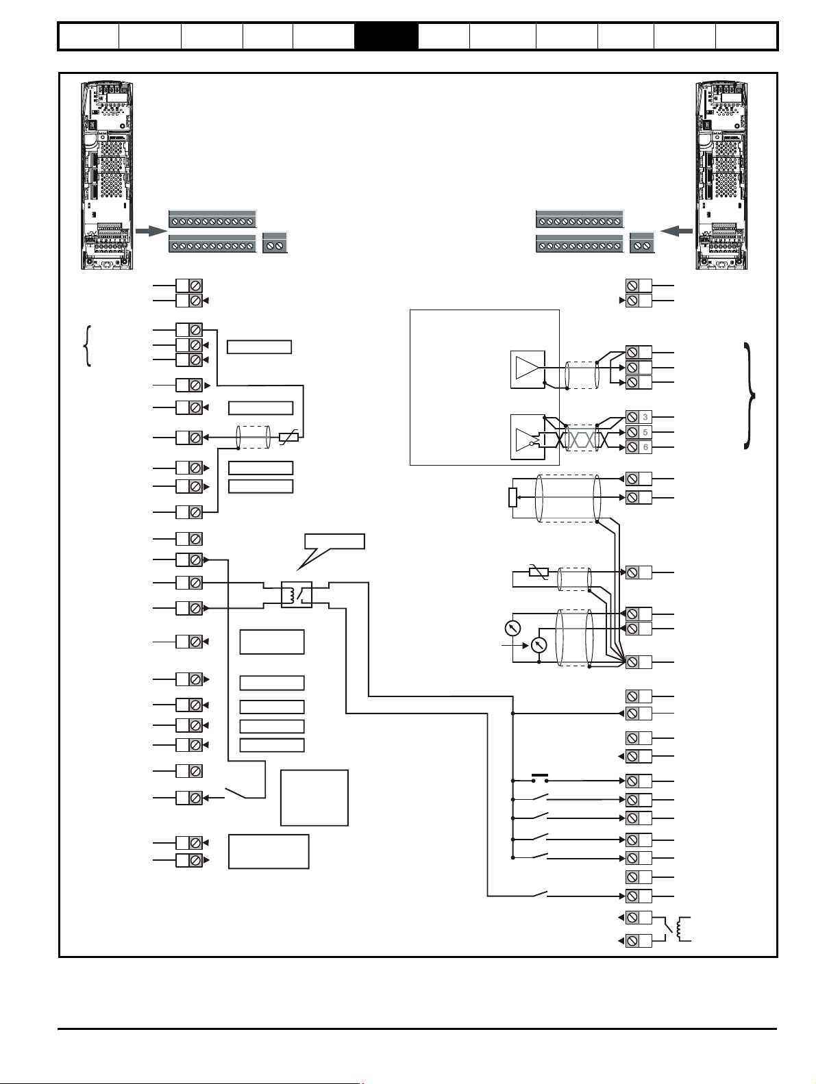
Safety
A
A
1
Information
Introduction
Product
information
System
Figure 6-18 Default terminal functions
design
Mechanical
installation
Electrical
installation
Getting
started
Optimisation Parameters
Te ch n ic a l
data
Component
sizing
Diagnostics
0V common
External +24V input
0V common
Non inverting
Inverting
Analogue input 1
+10V output
Analogue input 2
Analogue input 3
Analogue output 1
Analogue output 2
0V common
Regen drive
Polarised signal
connectors
1
21 31
1
2
3
5
6
4
7
8
9
10
11
11
42
41
User definable
User definable
User definable
User definable
Regen inductor
thermistor
Analogue frequency/speed
reference 1
Connections for
single-ended input
differential input signal
frequency/speed
signal
Connections for
nalogue
reference 2
Motoring drive
Polarised signal
connectors
1
21 31
11
42
41
1
3
5
2
6
0V common
External +24V input
0V common
Non inverting
Inverting
Analogue input
0V common
Non inverting
Inverting
4
7
+10V output
Analogue input 2
0V common
+24V output
0V common
Enable motor drive
Contactor closed
Drive healthy
Reset input
0V common
Secure Disable/
Drive enable**
Status relay
21
22
23
24
25
26
27
28
29
30
31
41
42
Enable relay
Input from
regen circuit
User definable
User definable
User definable
User definable
Used for control
of external regen
system contactors
Optional
Enable
connected
through Regen
system
auxiliaries
nalogue input 3
(Motor thermistor*)
Speed /
frequency
Torque
(active
current)
8
Analogue input 3
9
10
11
21
22
23
24
25
26
27
28
29
30
31
41
42
Analogue output 1
Analogue output 2
0V common
0V common
+24V output
0V common
At zero speed
Reset
Run forward
Run reverse
Analogue input 1
/ input 2 select
Jog forward
0V common
Secure Disable/
Drive enable**
Status r elay drive healthy
* Analogue input 3 can be configured as a motor thermistor input, refer
to the Unidrive SP User Guide.
**The Secure Disable / Drive enable terminal is a positive logic input only.
Unidr ive SP Re gen Inst allatio n Guide 85
Issue Number: 2 www.controltechniques.com
Page 86
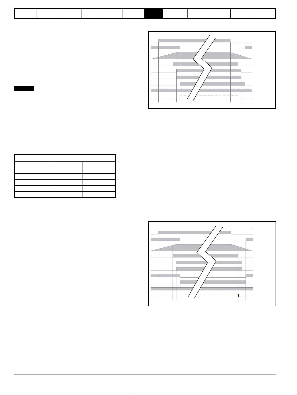
Safety
y
56
8S19
Information
Introduction
Product
information
System
design
Mechanical
installation
Electrical
installation
7 Getting started
7.1 Regen parameter settings
7.1.1 Switching frequency Pr 5.18 (Pr 0.41)
Set the switching frequency on the Regen drive to the required value
(3kHz default value).
A higher switching frequency setting has the following advantages:
• Line current ripple at the switching frequency is reduced, giving
improved waveform quality.
• Acoustic noise produced by the line inductors is reduced.
• Dynamic DC bus voltage response is improved.
NOTE
In some cases, setting the switching frequency to a value greater than
the default 3kHz results in current derating. Refer to Chapter 12
Technical Data in the Unidrive SP User Guide.
7.1.2 DC bus voltage set point
The table below defines the DC Bus voltage set point levels, assuming a
tolerance of ±10% on the given supply voltage. The minimum value is
defined as the peak input voltage plus some headroom. Headroom is
required by the drive to allow correct control of the current. It is advisable
to set the voltage below the maximum value to give more allowance for
transient voltage overshoots.
Table 7-1 DC bus voltage set point - Pr 3.05 (Pr 0.01)
The DC bus voltage set point, see Pr 3.05 (Pr 0.01), should be set to a
level that is suitable for the AC supply voltage being used. It is very
important that the Regen drive DC bus voltage set point Pr 3.05
(Pr 0.01) is set above the peak AC supply voltage by at least 50Vac.
7.2 Regen drive sequencing
When a Regen drive is enabled, it goes through a line synchronisation
sequence. During this procedure, test pulses are applied to the incoming
line to determine the voltage and phase. When it has been successfully
synchronised to the line, the DC bus voltage controller is enabled and
the DC bus voltage rises to the target voltage.
Only when all of these stages have been completed successfully is the
motoring drive enabled. If at any time there is a fault, or the Regen drive
is disabled, the motoring drive will also be disabled.
This sequence of events is important to prevent damage to the Regen
drive, motoring drive or external power circuit components.
The sequence of events is as follows:
N
Voltage levels DC Bus voltage set-point
Supply voltage
Vac
200 350 350
400 700 700
575 835 835
690 1005 1005
Default
Vdc
Recommended
Vdc
Getting
started
Optimisation Parameters
Technical
data
Component
sizing
Diagnostics
Power applied and power removed 400V system
Single Regen: Single Motoring
K1
K3
Vdc
Drive Health
K2
Aux.2
Aux.1
Aux.3
1234
7
1. K1 (main supply contactor / isolator) is closed with charging circuit
active (K3 closed).
2. DC bus charges through the Regen drives Vac inputs L1, L2, L3
(charging circuit)
3. If the DC Bus > 430Vdc then K2 Regen drive main contactor and
Aux.2 are closed via Regen drives relay, control terminals 41, 42.
4. K3 charging contactor is opened via K2 (Regen drive main
contactor) and Aux.1 closes. The Regen drive enable, S1 can now
be applied
5. The Regen drive and motoring drives can be enabled (enable signal
from Regen drive to motoring drives active, control terminal 24)
6. K1 (main supply contactor / isolator) is opened removing power from
the regen system.
7. DC bus discharges to 410Vdc at which point drive the healthy relay
becomes in-active. The Regen drives enable is removed. The
motoring drives enable signal from Regen drive becomes in-active
8. Regen drive main contactor, K2 is opened via the drive healthy relay,
control terminals 41, 42. Aux.2 opens informing the drive that the
Regen drives main contactor K2 is open.
9. K3 charging contactor is closed and Aux.1 opens
Power applied and power removed 400V system
Single Regen: Multiple Motoring (Unidrive SPMC)
K1
K3
Vdc
Drive Healthy
K2
Aux.2
Aux.2A
Aux.1
Aux.3
S1
1234 5 678
1. K1 (main supply contactor / isolator) is closed with charging circuit
active (K3 closed).
2. DC bus charges through Unidrive SPMC (charging circuit).
3. If the DC Bus > 430Vdc then K2 Regen drive main contactor and
Aux.2 are closed via Regen drives relay, control terminals 41, 42.
4. K3 charging contactor is opened via K2 (Regen drive main
contactor), SPMC 24Vdc is removed Aux.2A and Aux.1 closes. The
Regen drive enable, S1 can now be applied.
5. The Regen drive and motoring drives can be enabled (enable signal
from Regen drive to motoring drives active, control terminal 24).
6. K1 (main supply contactor / isolator) is opened removing power from
the regen system.
9
86 Unidrive SP Regen Installation Guide
www.controltechniques.com Issue Number: 2
Page 87
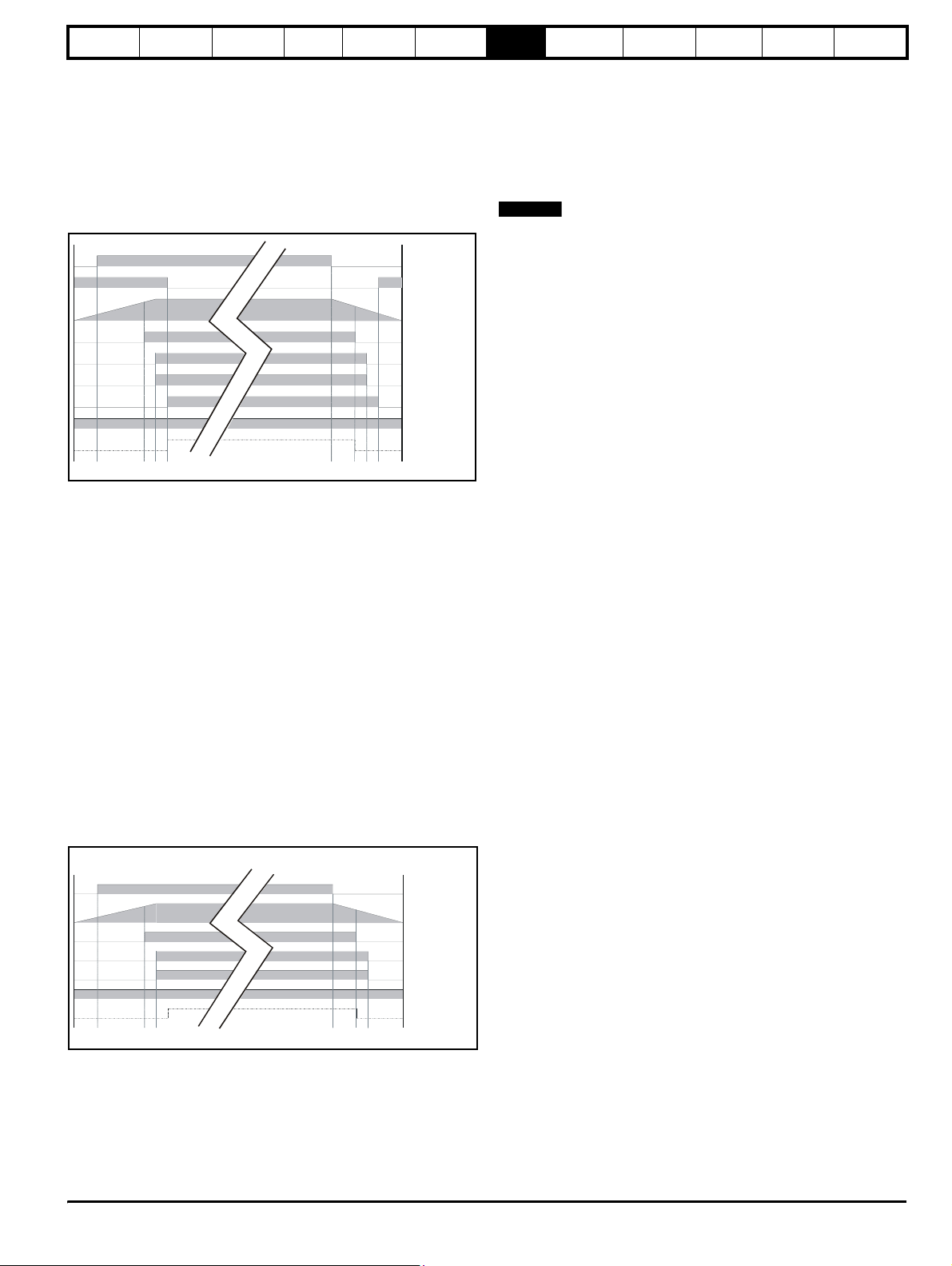
Safety
56
8S19
Information
Introduction
Product
information
System
design
Mechanical
installation
Electrical
installation
7. DC bus discharges to 410Vdc at which point drive the healthy relay
becomes in-active. The Regen drives enable is removed. The
motoring drives enable signal from Regen drive becomes in-active.
8. Regen drive main contactor, K2 is opened via the drive healthy relay,
control terminals 41, 42.
9. Aux.2 opens informing the drive that the Regen drives main
contactor K2 is open. K3 charging contactor is closed and Aux.1
opens.
Power applied and power removed 400V system
Single Regen: Multiple Motoring - external charging resistor
K1
K3
Vdc
Drive Healthy
K2
Aux.2
Aux.1
Aux.3
1234
7
1. K1 (main supply contactor / isolator) is closed with charging circuit
active (K3 closed).
2. DC bus charges through the external charging resistors (charging
circuit).
3. If the DC Bus > 430Vdc then K2 Regen drive main contactor and
Aux.2 are closed via Regen drives relay, control terminals 41, 42.
4. K3 charging contactor is opened via K2 (Regen drive main
contactor) and Aux.1 closes. The Regen drive enable, S1 can now
be applied.
5. The Regen drive and motoring drives can be enabled (enable signal
from Regen drive to motoring drives active, control terminal 24).
6. K1 (main supply contactor / isolator) is opened removing power from
the regen system.
7. DC bus discharges to 410Vdc at which point drive the healthy relay
becomes in-active. The Regen drives enable is removed. The
motoring drives enable signal from Regen drive becomes in-active.
8. Regen drive main contactor, K2 is opened via the drive healthy relay,
control terminals 41, 42. Aux.2 opens informing the drive that the
Regen drives main contactor K2 is open.
9. K3 charging contactor is closed and Aux.1 opens
Power applied and power removed 400V system
Regen brake resistor replacement
K1
Vdc
Drive Healthy
K2
Aux.2
Aux.1
S1
12345678
1. K1 (main supply contactor / isolator) is closed.
2. DC bus charges through motoring drives L1, L2, L3 Vac inputs.
3. If the DC Bus > 430Vdc then K2 Regen drive main contactor and
Aux.2 are closed via Regen drives relay, control terminals 41, 42.
4. Regen drive enable, S1 can now be applied.
5. The Regen drive and motoring drives can be enabled (enable signal
from Regen drive to motoring drives active, control terminal 24).
Getting
started
Optimisation Parameters
Te ch ni ca l
data
Component
sizing
Diagnostics
6. K1 (main supply contactor / isolator) is opened removing power from
the regen system.
7. DC bus discharges to 410Vdc at which point drive the healthy relay
becomes in-active. The Regen drives enable is removed. The
motoring drives enable signal from Regen drive becomes in-active.
8. Regen drive main contactor, K2 is opened via the drive healthy relay,
control terminals 41, 42. Aux.2 opens informing the drive that the
Regen drives main contactor K2 is open.
NOTE
N
When the Regen drive has powered-up and the DC bus voltage has
exceeded 430Vdc, Pr 3.07 changes from 0 to 1 activating the drives
relay which in turn closes the Regen drive main contactor. If either the
DC bus voltage falls below the contactor open voltage (410Vdc) or the
system is synchronised and the AC voltage falls below contactor open
voltage (150Vac), Pr 3.07 will change from a 1 to 0 opening the Regen
drive main contactor.
Synchronisation:
• Apply test pulses to line to determine magnitude and phase.
• Attempt to synchronise to the line.
• If synchronisation is successful then enable the DC bus voltage
controller.
DC bus voltage controller active:
• DC bus voltage rises to reference level.
• Motoring drive enabled by digital output from Regen drive.
Motoring drive active:
• The motor may now be energised and rotated.
• Power flows to and from the line as necessary via the Regen drive.
• DC bus voltage remains stable.
·
Whilst running if:
• The line voltage dips too low
The Regen drive synchronises to the Vac supply and therefore
knows the supply voltage (Pr 5.02)
• OR the DC bus voltage goes out of regulation
DC bus drops below the contactor open voltage level (410 Vdc)
• OR there is any trip on the Regen drive
Drive healthy no longer active. Regen and motoring drive(s)
enable removed
• OR the supply contactor is de-energised
Aux.2 connected to control terminal 25 of Regen drive
• OR the Regen drive is disabled
• OR the MCB trips
Switching frequency filter or external charging resistor
Then:
• the Regen drive will inhibit
• the motoring drive will be disabled by the Regen drive
• the Regen drive main contactor will be opened
7.2.1 Sequence
The motoring drive must only be enabled when the Regen drive is
enabled, healthy, and synchronised to the AC supply. This will prevent
any damage to the regen drive start-up circuit and prevent OV trips.
7.3 Regen drive commissioning
• Ensure power and control connections are made as specified in this
Installation Guide.
• Ensure the Regen and motoring drives are not enabled.
• Switch on the AC supply.
• Both the Regen and motoring drives should now power up through
the relevant start-up circuits in standard open loop mode.
• On the Regen drive, configure the drive type Pr 11. 31 (Pr 0.48) to
REGEN.
• The main contactors should now close; the relevant start-up circuit is
disabled at this point.
• On the Regen drive, set up the switching frequency and DC bus set
point voltage to the required values in either Menu 0 or Menu 3, refer
to section 7.1.2 DC bus voltage set point . Save the parameters.
Unidr ive SP Re gen Inst allatio n Guide 87
Issue Number: 2 www.controltechniques.com
Page 88
Safety
Information
Introduction
Product
information
System
design
Mechanical
installation
Electrical
installation
• The Regen drive can now be enabled, the Regen drive should
display ACT.
• The commissioning of the motoring drive(s) can now be carried out.
7.4 Motoring drive commissioning
7.4.1 Motoring drive enable
When the Regen drive has been successfully synchronised, Pr 3.09 on
the Regen drive will become active and digital output F1 on terminal 24
also becomes active allowing the motoring drive(s) to be enabled. If the
Regen drive trips or attempts to re-synchronise to the supply, Pr 3.09
becomes zero and the enable signal for the motoring drive(s) is
removed.
The setting of certain parameters in the motoring drive must be given
special consideration when used in a regen system.
7.4.2 Ramp Mode - Pr 2.04 (Pr 0.15)
When a motoring drive is used in a regen system, the ramp mode should
be set to FAST. The default setting of standard control will result in
incorrect operation.
7.4.3 Voltage Control Mode - Open loop only Pr 5.14
(Pr 0.07)
The default setting of UR_I does not function correctly in the motoring
drive when used in a regen system. When the system is powered up, the
motoring drive is disabled while the Regen drive synchronises to the AC
supply. The resultant delay before the motoring drive is enabled means
that the stator resistance test cannot be completed. When open loop
vector operation is required the voltage mode should be set to UR_S.
7.4.4 AC Supply Loss Mode - Pr 6.03
The motoring drive will not operate correctly if the AC supply loss mode
is set to STOP. If the AC supply is lost, the Regen drive disables the
motoring drive and prevents a controlled stop from being completed.
Getting
started
Optimisation Parameters
Technical
data
Component
sizing
Diagnostics
88 Unidrive SP Regen Installation Guide
www.controltechniques.com Issue Number: 2
Page 89
Safety
eedbac
A
A
Information
Introduction
Product
information
System
design
Mechanical
installation
Electrical
installation
8 Optimisation
The following section covers optimisation of the regen system which can
be carried out by the user.
Feature Detail
Power feed-forward
Voltage controller gain
Current loop gains
Power factor correction
The Regen drive uses a DC bus voltage controller with inner current
controllers as shown in Figure 8-1 Regen controllers :
Figure 8-1 Regen controllers
3.05
Pr DC
bus voltage
set point
-
DC bus
voltage
f
The gains of the voltage and current controllers affect the stability of the
Regen system, with incorrect settings resulting in over-voltage or overcurrent trips.
8.1 Power feed-forward compensation
(Pr 3.10)
Power feed-forward compensation can be used to reduce the transient
DC bus voltages produced when a fast load transient occurs on the
motoring drives connected to the Regen drive.
100.0% power feed-forward is equivalent to an active current of:
Drive rated current / 0.45 (i.e. over current trip level)
and a Vac terminal peak phase voltage equal to:
DC_VOLTAGE_MAX / 2
This scaling is the same as the power output from Pr 5.03 when highspeed output mode is used (Refer to section 9.7 Menu 7: Analogue I/O ).
Therefore an analogue output from the drive supplying the load, and
analogue input 2 or 3 of the drive acting as the supply Regen drive can
be connected together to give power feed-forward compensation without
further scaling if the two drives are of equal rating.
If the ratings are different the analogue input scaling must be used to
give the correct power feed-forward, where the scaling is given by (load
drive) drive rated current / (Regen drive) drive rated current.
Figure 8-2 shows the Regen drives analogue inputs and motoring drives
analogue outputs which can be used to pass Pr 5.03 (motoring drive
output power) to the Regen drive which is then used for the power
feedforward.
Power feed-forward can be used to reduce fast transient DC Bus voltage effects produced by transient load conditions on
motoring drives mainly in Dynamic applications
where spurious over-voltage and/or over-current trips are experienced.
The voltage controller gain can be implemented to overcome instability in the DC voltage on the common DC Bus in the
following conditions,
• A brake resistor replacement system where the ratio between regen brake drive and motoring drive(s) DC Bus
capacitance is large
• With multiple motoring drive(s) where the ratio between the regen drive(s) and motor drive(s) DC Bus capacitance is
large.
Ensure the voltage controller gain is not increased to high as this can also introduce excessive ripple and instability on
the DC Bus.
The current loop gains can be optimised to overcome spurious over-current trips during either synchronisation to the
power supply, or during operation.
The default gain settings are sufficient for most applications however these can be modified with the proportional (Kp)
being the most critical for stability.
This does not optimize the regen system but improves the power factor of the supply that is connected to the regen
system.
• Will introduce cost saving (electricity bill), compensate for inductive loads on the same supply, and overcome voltage
drops due to “soft supplies”.
• A separate power factor correction unit may not be required.
• The symmetrical current limit must be below its maximum in order for power factor correction to work (therefore may
be limited due to regen drive size).
Voltage
controller
Current
controllers
-
Current
k
feedback
Getting
started
Optimisation
Parameters
Technical
data
Component
sizing
Diagnostics
Only one analogue output from the motoring drive and one analogue input
to the Regen drive is required to configure the power feedforward term.
Figure 8-2 Power Feedforward configurations
Pr set-up
Analogue input 2
Destination Pr
= 3.10
7.12
Scaling Pr
Analogue input 3
Destination Pr
= 3.10
Scaling Pr
7.16
7.14
7.18
Regen drive
Analogue I/P 2
Analogue I/P 3
0V common
Motoring drive
7
8
11
9
Analogue O/P 1
Analogue O/P 2
10
11
0V common
Pr set-up
nalogue output 1
7.19
Source Pr =
5.03
Mode Pr =
7.21
H.SPd
nalogue output 2
7.22
Source Pr = 5.03
7.24
Mode Pr =
H.SPd
8.2 Current loop gains
The defaults current loop gains (Kp, Pr 4.13 and Ki, Pr 4.14) are suitable
for most standard regen systems. However if the input inductance is
significantly higher the proportional gain may need to be adjusted as
described following.
The most critical parameter for stability is the current controller
proportional gain, Pr 4.13. The required value for this is dependent
upon the Regen drives input inductance. If the inductance of the supply
is a significant proportion of the recommended regen inductor
i.e. 60/I
Where:
I
DR
then the proportional gain may need to be increased.
The supply inductance is likely to be negligible compared to the regen
inductor value with small drives, but is likely to be significant with larger
drives. The proportional gain, Pr 4.13 should be adjusted as described
following using the total inductance per phase.
The proportional gain, Pr 4.13 can be set by the user so that
Pr 4.13 = Kp = (L / T) x (I
Where:
T is the sample time of the current controllers. The drive compensates
for any change of sample time, and so it should be assumed that the
sample time is equivalent to the lowest sample rate of 167µs.
mH per phase,
DR
is the drive rated current
fs
/ Vfs) x (256 / 5)
Unidr ive SP Re gen Inst allatio n Guide 89
Issue Number: 2 www.controltechniques.com
Page 90
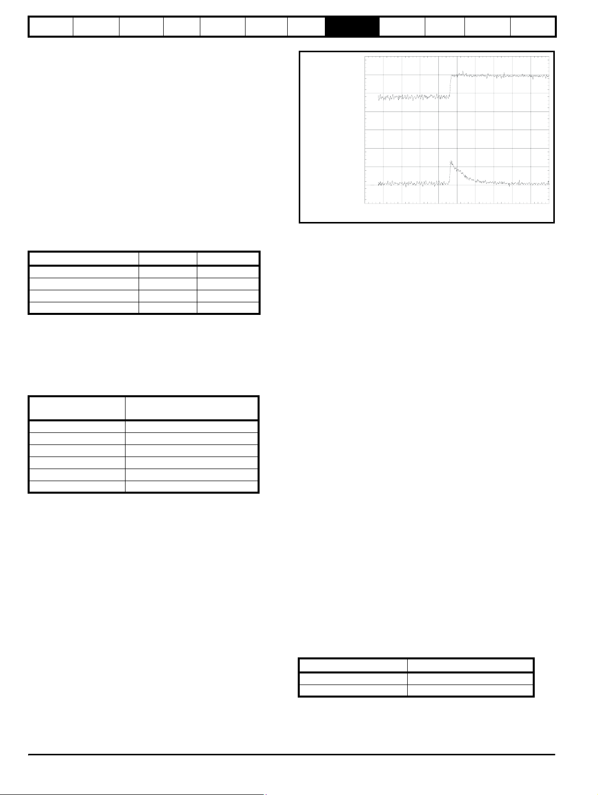
Safety
Information
Introduction
Product
information
System
design
Mechanical
installation
Electrical
installation
L is the total input inductance. This is the inductance value in Pr 3.02 (at
power-up this parameter is zero). Each time the Regen drive is enabled
the total input inductance is measured and displayed in Pr 3.02. The
value given is only approximate, and will give an indication as whether
the input inductance is correct for the sinusoidal rectifier unit size. The
measured value should include the supply inductance as well as the
Regen drives input inductors, however, the supply filter capacitance,
masks the effect of the supply inductance. Therefore the value
measured is usually the Regen drive regen inductor value.
I
is the peak full-scale current feedback
fs
= Drive rated current x √2 / 0.45 (Drive rated current [Pr 11. 32])
I
fs
Vfs is the maximum DC bus voltage.
Therefore:
Pr
4.13
= Kp = (L / 167µs) x (Drive rated current x √2 / 0.45 / Vfs) x (256 / 5)
= K x L x Rated drive current
Where:
K = √2 / (0.45 x Vfs x 167µs) x (256 / 5)
Drive voltage rating Vfs K
200V 415V 2322
400V 830V 1161
575V 990V 973
690V 1190V 809
This set-up will give a step response with minimum overshoot after a
step change of current reference. The approximate performance of the
current controllers will be as given below. The proportional gain can be
increased by a factor of 1.5 giving a similar increase in bandwidth,
however, this gives a step response with approximately 12.5%
overshoot.
Table 8-1 Current loop sample times
Switching frequency
kHz
Current control sample time (T)
µs
3 167
4 125
683
8 125
12 83
16 125
As previously detailed the current controller integral gain, Pr 4.14 is not
so critical with the recommended value being the default setting.
8.3 Voltage controller gain (Pr 3.06)
Even when the voltage controller gain is set correctly there will be a
transient change of DC bus voltage when there is a change in the load
on any motoring drive connected to the Regen drive. This can be
reduced substantially by using an analogue input for power feed forward
compensation.
The following discussion relates to a system without power feed-forward
compensation.
If the power flow from the supply is increased (i.e. more power is taken
from the supply or less power is fed back into the supply) the DC bus
voltage will fall, but the minimum level will be limited to just below the
peak rectified level of the supply provided the maximum rating of the unit
is not exceeded.
If the power flow from the supply is reduced (i.e. less power is taken from
the supply or more power is fed back into the supply) the DC bus voltage
will rise. During a rapid transient the DC bus will rise and then fall as
shown in Figure 8-3 DC Bus transient .
Getting
started
Optimisation
Parameters
Technical
data
Component
sizing
Diagnostics
Figure 8-3 DC Bus transient
ch3: dT= 194ms dV=2.24 V
Active regen
unit current
Regen unit
DC bus voltage
50ms/div
The example shown is for a very rapid load change where the torque
reference of the motor drive has been changed instantly from one value
to another.
The proportional gain of the voltage controller, Kp, Pr 3.06, defines the
voltage transient because the integral term is too slow to have an effect.
(In applications where the motor drive is operating under speed control,
the speed controller may only require a limited rate of change of torque
demand, and so the transient voltage may be less than covered in the
discussion below.)
If the DC Bus voltage set point voltage Pr 3.05, plus the transient rise
exceed the over-voltage trip level the Regen drive will trip.
When a 400V motor is operated above base speed from a drive in
closed loop vector mode, fed from the Regen drive with the same rating,
supplying a DC voltage of 700V, and an instantaneous change of torque
is demanded (i.e. -100% to +100%) the peak of the voltage transient
(∆V) is approximately 80V if the current controllers are set up correctly
and the voltage controller uses the default gain. (Operating with
maximum voltage on the motor, i.e. above base speed, gives the biggest
transient of power and hence the biggest value of (∆V. )
If the load change, drive voltage rating, motor voltage or DC Bus voltage
set point are different then ∆V is calculated from:
∆V = 80V x K
L
x K
x KMV x K
RAT
SP
Where:
= Load change / 200%
K
L
K
= Drive voltage rating / 400
RAT
= Motor voltage / 400
K
MV
= 700 / DC bus voltage set point
K
SP
In some applications, particularly with a high DC bus voltage set point
and low switching frequency it may be necessary to limit the rate of
change of power flow to prevent over voltage trips. A first order filter on
the torque reference of the motor drive (Pr 4.12) is the most effective
method to reduce the transient further. (A fixed limit of the rate of change
of torque demand is less effective.) Table 8-2 Rate of change gives an
approximate indication of the reduction in ∆V for different time constants.
(As already mentioned the value of ∆V given is for an instantaneous
change of torque representing the worst case. In applications where a
speed controller is used in the motor drive the transient will already
include an inherent filter).
Table 8-2 Rate of change
Time constant Change in ∆V
20ms x 0.75
40ms x 0.5
The transient produced is approximately proportional to the voltage
controller gain Pr 3.06. The default voltage controller gain is set to give a
value that is suitable for most applications. The gain may need to be
increased if the DC bus capacitance is high compared to two drives of
90 Unidrive SP Regen Installation Guide
www.controltechniques.com Issue Number: 2
Page 91
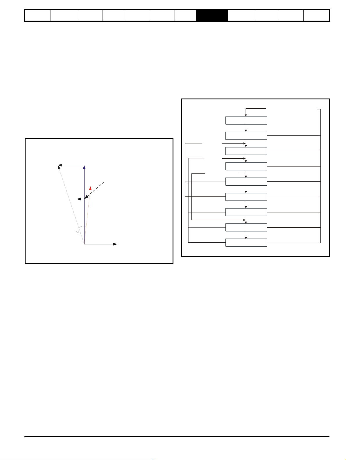
Safety
Information
Introduction
Product
information
System
design
Mechanical
installation
Electrical
installation
similar rating coupled together. However, care must be taken to ensure
that the gain is not too high as this can cause excessive ripple in the DC
bus voltage.
8.4 Power factor correction (Pr 4.08)
In regen mode it is possible to produce some current in the x axis of the
reference frame so that the Regen drive can be made to produce or
consume reactive power. Pr 4.08 defines the level of reactive current as
a percentage of the regen drives rated current (Pr 5.07). Positive
reactive current produces a component of current flowing from the
supply to the drive at the Regen drive terminals that lags the respective
phase voltage, and negative reactive current produces a component of
current that leads the respective voltage. It should be noted that the
maximum current in regen mode is limited to DRIVE_CURRENT_MAX,
and so the drive applies a limit to this parameter
(REGEN_REACTIVE_MAX) to limit the current magnitude. Therefore
the symmetrical current limit (Pr 4.07) must be reduced below its
maximum value before Pr 4.08 can be increased from zero.
Figure 8-4 Power flow from supply to regen drive
Voltage across
regen inductor
JwLIr
Vs
Power
factor
Vs Supply voltage
Vr Voltage at regen drive terminals
Ir Total current at regen drive terminals
JwLIr Voltage across regen inductor
ϕ Power factor
Vr
Modifying Ir directly
affects power factor
Ir
X axis component of
Isx
current
Getting
started
Optimisation
Parameters
Technical
data
Component
sizing
Diagnostics
Mode 2 (Pr 3.11 = 1) is available to allow the current trimming to be
optimised, and overcome any inaccuracies due to noise / harmonics
from the AC Supply connected to the regen system.
If operating in Mode 2 (Pr 3.11 = 1) the auxiliary contact on the "Regen
drive main contactor" as shown in this installation guide needs to be
moved from T.31 to T.25 to allow the current trimming to be carried out
during each enable. The current trimming only occurs when the main
contactor is open, therefore when the regen drive enable signal is given
with Mode 2 (Pr 3.11 = 1) the main contactor will open and close before
the regen drive becomes active.
Both strategies are shown in the following state machine
Figure 8-5 Current trimming state diagram
Mains loss or contactor open
when it should be closed
Mains Loss
Supply o.k
Current Trim
Disabled
Disabled
Enabled Pr
Close Main Contactor
Waiting for Ena ble
3.11
=0
Open Contactor
Current Trim
Close Main Contactor
Active
(not synchronised)
Synchronied
Trim co mplete
Contactor closed + 100ms delay
Enabled (Pr3.11=1)
Contactor open + 100ms delay
Trim co mplete
Contactor closed + 100ms delay
Synchronised
8.5 Current trimming
From software V1.10 for Unidrive SP the current trimming can be user
configurable. The default setting for the current trimming in software
V1.10 is as with previous software versions.
The current trimming mode parameter (Pr 3.11) defines the strategy
used for trimming the current feedback when operating in regen mode
with Unidrive SP.
The two modes that can be selected are as detailed following
Mode 1 - At power up only [Pr 3.11 = 0]
Current trimming is only carried out once after power-up, as
previously available (pre software V1.10) with Unidrive SP Regen.
Mode 2 - At power up and on each enable [Pr 3.11 = 1]
Current trimming is carried out as previously available, once after
power-up, and now in addition it is also carried out before the drive
runs each time it is enabled (software V1.10 onwards) with Unidrive
SP Regen.
Unidr ive SP Re gen Inst allatio n Guide 91
Issue Number: 2 www.controltechniques.com
Page 92

Safety
Information
Introduction
Product
information
System
design
Mechanical
installation
Electrical
installation
Getting
started
Optimisation
Parameters
Technical
data
Component
sizing
Diagnostics
9 Parameters
9.1 Parameter ranges and variable maximums:
The two values provided define the minimum and maximum values for the given parameter. In some cases the parameter range is variable and
dependant on either:
• other parameters
• the drive rating
• drive mode
• or a combination of these
The values given in Table 9-1 are the variable maximums used in the drive.
Table 9-1 Definition of parameter ranges & variable maximums
Maximum Definition
Maximum motor rated current
RATED_CURRENT_MAX
[9999.99A]
DRIVE_CURRENT_MAX
[9999.99A]
RATED_CURRENT_MAX = 1.36 x Rated drive current.
The rated current can be increased above the Regen drive rated current up to a level not exceeding 1.36 x
Regen drive rated current. (Maximum rated current is the maximum Normal Duty current rating.)
The actual level varies from one drive size to another, refer to Table 3-2 on page 14.
Maximum drive current
The maximum drive current is the current at the over current trip level and is given by:
DRIVE_CURRENT_MAX = Regen drive rated current / 0.45
Unidrive SP in regen mode operates in a reference frame that is aligned to the voltage at the drive terminals. As
the phase shift across the input inductors is small, the reference frame is approximately aligned with the supply
voltage. The maximum normal operating current is controlled by the current limits.
DRIVE_CURRENT_MAX is used in calculating the maximum of some parameters and is fixed at 1.75 x rated
drive current. The drive can operate up to this level under normal conditions.
CURRENT_LIMIT_MAX is used as the maximum for some parameters such as the user current limits. The
maximum current limit is defined as follows (with a maximum of 1000%):
Maximum current
⎛⎞
CURRENT_LIMIT_MAX
------------------------------------------------------------- ------------
⎝⎠
Regen drive rated current
100%×=
CURRENT_LIMIT_MAX
[1000.0%]
TORQUE_PROD_CURRENT_MAX
[1000.0%]
USER_CURRENT_MAX
[1000.0%]
DC_VOLTAGE_SET_MAX
[1150V]
DC_VOLTAGE_MAX
[1190V]
POWER_MAX
[9999.99kW]
Where:
The Regen drive rated current is give by Pr 5.07
The maximum current is either 1.75 x rated drive current when the rated current set by Pr 5.07 is ≤maximum
Heavy Duty current rating, otherwise it is 1.1 x maximum rated current.
The rated active and rated magnetising currents are calculated from regen mode rated current (Pr 5.07) as:
Rated active current = Regen mode rated current
Rated magnetising current = 0
In this mode, the drive only requires the regen mode rated current to set the maximum current limit correctly
and scale the current limits, and so no user autotuning is required to set these accurately.
It is possible to set a level of reactive current with Pr 4.08 in regen mode. This parameter has a limit defined as
REGEN_REACTIVE_MAX that is provided to limit the total current to DRIVE_CURRENT_MAX.
REGEN_REACTIVE_MAX
Reactive drive current 1.75×
⎛⎞
------------------------------------------------------------ ---------------------
⎝⎠
Regen drive rated current
2
–
Pr 4.07
2
100%×=
Motor rated current is given by Pr 5.07
Maximum torque producing current
This is used as a maximum for the real current (active current) in a Regen drive.
Current parameter limit selected by the user
The user can select a maximum for Pr 4.08 (reactive current reference) and Pr 4.20 (active current reference)
to give suitable scaling for analogue I/O with Pr 4.24. This maximum is subject to a limit of
MOTOR1_CURRENT_LIMIT_MAX. USER_CURRENT_MAX = Pr 4.24
Maximum DC voltage set-point
400V rating drive: 0 to 800V
Maximum DC bus voltage
The maximum measurable DC bus voltage
400V drives: 830V
Maximum power in kW
The maximum power has been chosen to allow for the maximum power that can be output by the drive with
maximum AC output voltage, maximum controlled current and unity power factor. Therefore:
Software V01.07.01 and earlier: POWER_MAX = √3 x AC_VOLTAGE_MAX x RATED_CURRENT x 1.75
Software V01.08.00 and later: POWER_MAX = √3 x AC_VOLTAGE_MAX x DRIVE_CURRENT_MAX
The values given in square brackets indicate the absolute maximum value allowed for the variable maximum.
92 Unidrive SP Regen Installation Guide
www.controltechniques.com Issue Number: 2
Page 93

Safety
Information
Introduction
Product
information
System
design
Mechanical
installation
Electrical
installation
Getting
started
Optimisation
Parameters
Te ch ni ca l
data
Component
sizing
Diagnostics
9.2 Menu 0: Basic parameters
Table 9-2 Unidrive SP Regen menu 0 parameter descriptions
Parameter
0.00 xx.00 0 to 32,767 0 RW Uni
0.01 Voltage setpoint {3.05} 0 to DC_VOLTAGE_SET_MAX V 700 Vdc RW Uni US
0.02 Voltage controller Kp gain {3.06} 0 to 65535 4000 RW Bi US
0.03 Enable motor drive {3.09} OFF (0) or On (1) RO Uni NC
0.04 DC bus voltage {5.05} 0 to +DC_VOLTAGE_MAX V RO Uni FI NC PT
0.05 Output / supply voltage {5.02} 0 to AC_VOLTAGE_MAX V RO Uni FI NC PT
0.06 Regen drive status {3.03} 0 to 15 RO Uni NC PT
0.07 Regen restart mode {3.04}0 to 2 1RWUniUS
0.08 Close soft start contactor {3.07} OFF (0) or On (1) RO Uni NC
0.09 Soft start contactor closed {3.08} OFF (0) or On (1) RO Uni NC
0.10 Power feed forward compensation {3.10} ±100.0 % 0.0 RW Bi NC
0.11 Output / supply frequency {5.01} ±100.0 Hz RO Bi FI NC PT
0.12 Current magnitude {4.01} 0 to DRIVE_CURRENT_MAX A RO Uni FI NC PT
0.13 Active current {4.02} ±DRIVE_CURRENT_MAX A RO Bi FI NC PT
0.14 Output / supply power {5.03}±POWER_MAX kW RO Bi FI NC PT
0.15 Reactive power {3.01} ±POWER_MAX kVAR’s RO Bi FI NC PT
0.16 Input inductance {3.02} 0.000 to 500.000 mH RO Uni NC PT
0.17 Reactive current reference {4.08} ±REGEN_REACTIVE_MAX % 0.0 RW Bi US
0.18 Positive logic select {8.29} OFF (0) or On (1) On (1) RW Bit PT US
0.19 T7 analogue input 2 mode {7.11}
0.20 T7 analogue input 2 destination {7.14}Pr 0.00 to 21.51 Pr 3.10 RW Uni DE PT US
0.21 T8 analogue input 3 mode {7.15}
0.22 Not used
0.23 Not used
0.24 Not used
0.25 Not used
0.26 Not used
0.27 Not used
0.28 Not used
SMARTCARD parameter data
0.29
previously loaded
0.30 Parameter cloning {11. 42 }
0.31 Drive voltage rating {11.33 } 200 (0), 400 (1), 575 (2), 690 (3) RO Txt NC PT
0.32 Maximum Heavy Duty current rating {11. 32} 0.00 to 9999.99A RO Uni NC PT
0.33 Not used
0.34 User security code {11.30}0 to 999 0RWUniNCPTPS
0.35 Serial mode {11.2 4} AnSI (0), rtU (1) rtU (1) RW Txt US
0.36 Baud rate {11.25}
0.37 Serial address {11.23}0 to 247 1RWUniUS
0.38 Current controller Kp gain {4.13} 0 to 30,000 45 RW Uni US
0.39 Current controller Ki gain {4.14} 0 to 30,000 1,000 RW Uni US
0.40 Not used
0.41 Maximum switching frequency {5.18} 0 to 5 (3, 4, 6, 8, 12, 16 kHz) 0 (3kHz) RW Uni US
0.42 Not used
0.43 Not used
0.44 Not used
0.45 Thermal time constant {4.15} 0.0 to 400.0 89.0 RW Uni US
0.46 Regen drive rated current {5.07} 0 to RATED_CURRENT_MAX A RW Uni US
0.47 Not used
0.48 User drive mode {11. 31 }
0.49 Security status {11 .44} L1 (0), L2 (1), Loc (2) L2 (1) RW Txt PT US
0.50 Software version {11. 29} 1.00 to 99.99 RO Uni NC PT
0.51 to
Not used
0.59
11.36} 0 to 999 0 RO Uni NC PT US
{
0-20 (0), 20-0 (1), 4-20.tr (2), 20-4.tr (3),
4-20 (4), 20-4 (5), VOLt (6)
0-20 (0), 20-0 (1), 4-20.tr (2), 20-4.tr (3),
4-20 (4), 20-4 (5), VOLt (6), th.SC (7),
nonE (0), rEAd (1), Prog (2), AutO (3),
300 (0), 600 (1), 1200 (2), 2400 (3), 4800 (4),
57600 (8)*, 115200 (9)* *Modbus RTU only
th (8), th.diSP (9)
9600 (5), 19200 (6), 38400 (7),
OPEn LP (1), CL VECt (2),
SErVO (3), rEGEn (4)
Ú) Default(Ö)
Range(
boot (4)
VOLt (6) RW Txt US
VOLt (6) RW Txt US
nonE (0) RW Txt NC *
19200 (6) RW Txt US
rEGEn (4) RW Txt NC PT
Typ e
RW Read / Write RO Read only Uni Unipolar Bi Bi-polar Bit Bit parameter Txt Text string
FI Filtered DE Destination NC Not cloned RA Rating dependent PT Protected US User save PS Power down save
* Modes 1 and 2 are not user saved, Modes 0, 3 and 4 are user saved
Unidr ive SP Re gen Inst allatio n Guide 93
Issue Number: 2 www.controltechniques.com
Page 94

Safety
Information
Introduction
Product
information
System
design
Mechanical
installation
Electrical
installation
Getting
started
Optimisation
Parameters
Technical
data
Component
sizing
Diagnostics
9.3 Menu 3: Regen sequencer
In regen mode the drive assumes the mains is lost, it does not close the input, and does not attempt synchronisation if the DC bus voltage is below
the levels given in the table below.
If the unit is synchronised and the DC bus voltage falls below this level the unit is disabled and the Regen drive main contactor is opened.
The Regen drive also monitors the voltage at it's AC terminals (U, V and W) for mains loss and if this falls below the levels given in the table the unit
is disabled and the Regen drive main contactor is opened.
Vol tag e
rating
DC voltage mains loss
detection level
AC voltage mains loss
detection level
200 V 205 Vdc 75 Vac 215 Vdc
400 V 410 Vdc 150 Vac 430 Vdc
575 V 540 Vdc 225 Vac 565 Vdc
690 V 540 Vdc 225 Vac 565 Vdc
Figure 9-1 Menu 3 Regen logic diagram
Main
contactor
Enable
input
Power
feed-forward
compensation
Voltage
set-point
DC bus
voltage
closed
25
31
3.10
3.05
2.01
5.05
3.08
+
_
Power to
current
conversion
Kp gain
Regen
sequencer
3.04
3.06
Ki gain No user access
Regen
restart
mode
+
+
DC voltage for supply
healthy
2.013.03
Voltage
controller
kp gain
Current
control
(Menu 4)
Close start up
contactor
3.07
Enable
motor drive
3.09
Regen
status
Modulator
and power
circuit
Mains
supply
41
42
24
Key
Input
X
X
X
The parameters are all shown at their default settings
X
terminals
Output
terminals
0.XX
0.XX
Read-write (RW)
parameter
Read-only (RO)
parameter
Output
voltage
Output
power
Reactive
power
Output
frequency
Input
inductance
2.01
5.02
2.01
5.03
2.01
3.01
2.01
5.01
2.01
3.02
94 Unidrive SP Regen Installation Guide
www.controltechniques.com Issue Number: 2
Page 95
Safety
Information
Introduction
Product
information
System
design
Mechanical
installation
Electrical
installation
Getting
started
Optimisation
Parameters
Te ch ni ca l
data
Component
sizing
Diagnostics
Table 9-3 Menu 3 Regen parameter descriptions
Parameter
Ú) Default(Ö)
Range(
3.01 Reactive power ±POWER_MAX kVAR’s RO Bi FI NC PT
3.02 Input inductance 0.000 to 500.000 mH RO Uni NC PT
3.03 Regen drive status 0 to 15 RO Uni NC PT
3.04 Regen restart mode 0 to 2 1 RW Uni US
3.05 Voltage setpoint 0 to DC_VOLTAGE_SET_MAX V 700 Vdc RW Uni US
3.06 Voltage controller Kp gain 0 to 65535 4000 RW Bi US
3.07 Close start up contactor OFF (0) or On (1) RO Uni NC
3.08 Main contactor closed OFF (0) or On (1) 0 RO Uni NC
3.09 Enable motor drive OFF (0) or On (1) RO Uni NC
3.10 Power feed forward compensation ±100.0 % 0.0 RW Bi NC
3.11 Current trimming mode 0 to 1 0 RW Uni US
RW Read / Write RO Read only Uni Unipolar Bi Bi-polar Bit Bit parameter Txt Text string
FI Filtered DE Destination NC Not cloned RA Rating dependent PT Protected US User save PS Power down save
Typ e
Figure 9-2 Current trimming state diagram
Mains loss or contactor open
when it should be closed
Mains Loss
Supply o.k
Current Trim
Disabled
Disabled
Enabled Pr
Close Main Contactor
Waiting for Ena ble
3.11
=0
Open Contactor
Current Trim
Close Main Contactor
Active
(not synchronised)
Synchronied
Trim co mplete
Contactor closed + 100ms delay
Enabled (Pr3.11=1)
Contactor open + 100ms delay
Trim co mplete
Contactor closed + 100ms delay
Synchronised
3.01
Reactive power
Drive mode Regen
Coding
Bit SP FI DE Txt VM DP ND RA NC NV PT US RW BU PS
1 12111
Range Regen ±POWER_MAX kVAR’s
Update rate Background
The power (Pr 5.03) and the reactive power are the power or VAR's respectively that flow from the supply to the drive. Therefore when this parameter
is positive the phase current flowing from the supply to the drive contains a component that lags the respective phase voltage, and when this
parameter is negative the phase current contains a component which leads the respective phase voltage at the drive terminals.
Unidr ive SP Re gen Inst allatio n Guide 95
Issue Number: 2 www.controltechniques.com
Page 96
Safety
Information
Introduction
Product
information
System
design
Mechanical
installation
Electrical
installation
Getting
started
Optimisation
Parameters
Technical
data
Component
sizing
Diagnostics
3.02
Input inductance
Drive mode Regen
Coding
Bit SP FI DE Txt VM DP ND RA NC NV PT US RW BU PS
3111 1
Range Regen 0.000 to 500.000mH
Update rate Background
At power-up this parameter is zero. Each time the Regen drive is enabled the supply inductance is measured and displayed by this parameter. The
value given is only approximate, but will give an indication as whether the input inductance is correct for the sinusoidal rectifier unit size. The
measured value should include the supply inductance as well as the Regen drive input inductance, however, the supply filter capacitance, masks the
effect of the supply inductance. Therefore the value measured is usually the Regen drive input inductor value.
3.03
Regen status
Drive mode Regen
Coding
Bit SP FI DE Txt VM DP ND RA NC NV PT US RW BU PS
111 1
Range Regen 0 to 15
Update rate 4ms
If an L.Sync trip occurs Pr 3.03 indicates the reason. At power-up and on trip reset this parameter is set to zero. Once an L.Sync trip has occurred this
parameter shows when the trip occurred and the reason for the last L.Sync trip as indicated by the bits in the table below. The reasons for the trip are
either because the supply frequency is out of range or the PLL (phase lock loop) within the drive cannot synchronise to the supply waveforms.
Bit Status
0 Tripped during synchronisation
1 Tripped while running
2 Reason for trip was supply frequency <30.0Hz
3 Reason for trip was supply frequency >100.0Hz
4 Reason for trip was PLL could not be synchronised
3.04
Regen restart mode
Drive mode Regen
Coding
Bit SP FI DE Txt VM DP ND RA NC NV PT US RW BU PS
1 1111
Range Regen 0 to 2
Default Regen 1
Update rate Background
Pr 3.04 defines the action taken after enable and when a synchronisation failure occurs.
0, rESYnC: Continuously attempt to re-synchronise
1, del.triP: delayed trip
Attempt to synchronise for 30s. If unsuccessful after this time then give a LI.SYnC trip. After a failure during running attempt to re-synchronise for 30s
before tripping.
2, triP: immediate trip
Attempt to synchronise for 30s. If unsuccessful after this time then give a LI.SYnC trip. After a failure during running, trip immediately.
96 Unidrive SP Regen Installation Guide
www.controltechniques.com Issue Number: 2
Page 97
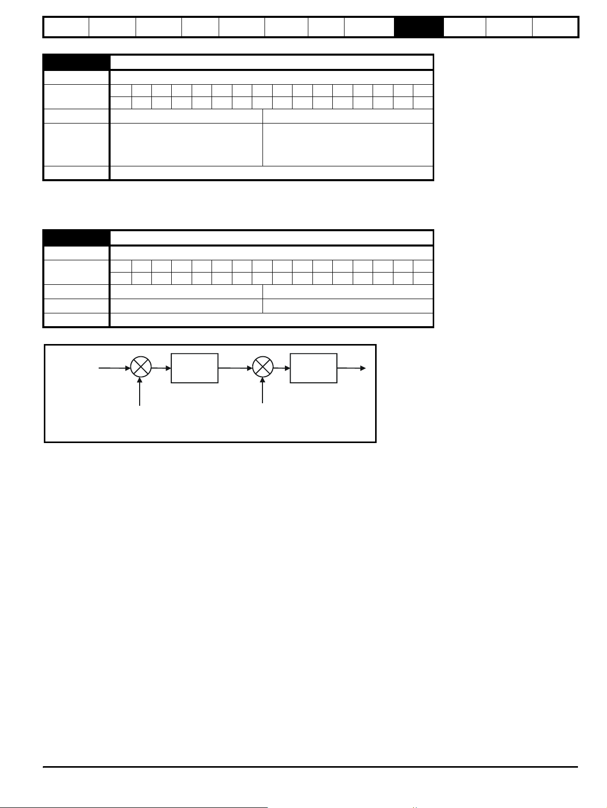
Safety
Information
Introduction
Product
information
System
design
Mechanical
installation
Electrical
installation
Getting
started
Optimisation
Parameters
Te ch ni ca l
data
Component
sizing
Diagnostics
3.05
Voltage set-point
Drive mode Regen
Coding
Bit SP FI DE Txt VM DP ND RA NC NV PT US RW BU PS
1 1 111
Range Regen 0 to DC_VOLTAGE_SET_MAX V
200V rating drive: 350
Default Regen
400V rating drive: 700
575V rating drive: 835
690V rating drive: 1005
Update rate Background
The Regen drive will attempt to hold the DC bus at the level specified by this parameter. The DC bus voltage must always be higher than the peak of
the line to line supply voltage if the unit is to operate correctly. The default values can be used with most supplies giving a reasonable level of control
headroom. However, with higher voltage supplies the set-point must be raised.
3.06
Voltage controller Kp gain
Drive mode Regen
Coding
Bit SP FI DE Txt VM DP ND RA NC NV PT US RW BU PS
111
Range Regen 0 to 65,535
Default Regen 4,000
Update rate Background
When the drive is operated as a Regen drive it uses a DC bus voltage controller with inner current controllers as shown below.
Pr DC
3.05
bus voltage
set point
-
DC bus
voltage
Voltage
controller
Current
controllers
-
Current
feedback
feedback
The gains of the voltage and current controllers affect the stability of the regen unit control system and incorrect gain settings can result in overvoltage or over-current trips. In many applications the default gains given for the current controllers (Pr 4.13 and Pr 4.14) will be suitable, however, it
may be necessary for the user to change these if the inductance or resistance of the supply plus the regen inductors varies significantly from the
expected values.
Setting the current controller gains
The most critical parameter for stability is the current controller proportional gain (Pr 4.13). The required value for this is dependent on the Regen unit
input inductance. If the inductance of the supply is a significant proportion of the recommended regen inductor (i.e. 60/IDR mH per phase, where IDR
is equivalent to Kc), then the proportional gain may need to be increased. The supply inductance is likely to be negligible compared to the regen
inductor value with small drives, but is likely to be significant with larger drives.
The proportional gain Pr 4.13 should be adjusted as described below using the total inductance per phase. The current controller integral gain Pr 4.14
is not so critical, and in a majority of cases the default value is suitable. However, if it is necessary to adjust this parameter it should be set up as
described below using the supply resistance for one phase.
The proportional gain Kp (Pr 4.13) is the most critical value in controlling the performance of the current controllers. The value can be set by the user
so that
Kp = (L / T) x (I
/ Vfs) x (256 / 5)
fs
Where:
T is the sample time of the current controllers. The drive compensates for any change of sample time, and so it should be assumed that the sample
time is equivalent to the lowest sample rate of 167µs.
L is the total inductance per phase
is the peak full scale current feedback = Kc x √2 / 0.45. Where Kc is the current scaling for each size of drive.
I
fs
V
is the maximum DC link voltage.
fs
Therefore:
Kp = (L / 167µs) x (Kc x √2 / 0.45 / V
) x (256 / 5) = K x L x Kc
fs
Where:
K = [√2 / (0.45 x V
x 167µs)] x (256 / 5)
fs
Unidr ive SP Re gen Inst allatio n Guide 97
Issue Number: 2 www.controltechniques.com
Page 98
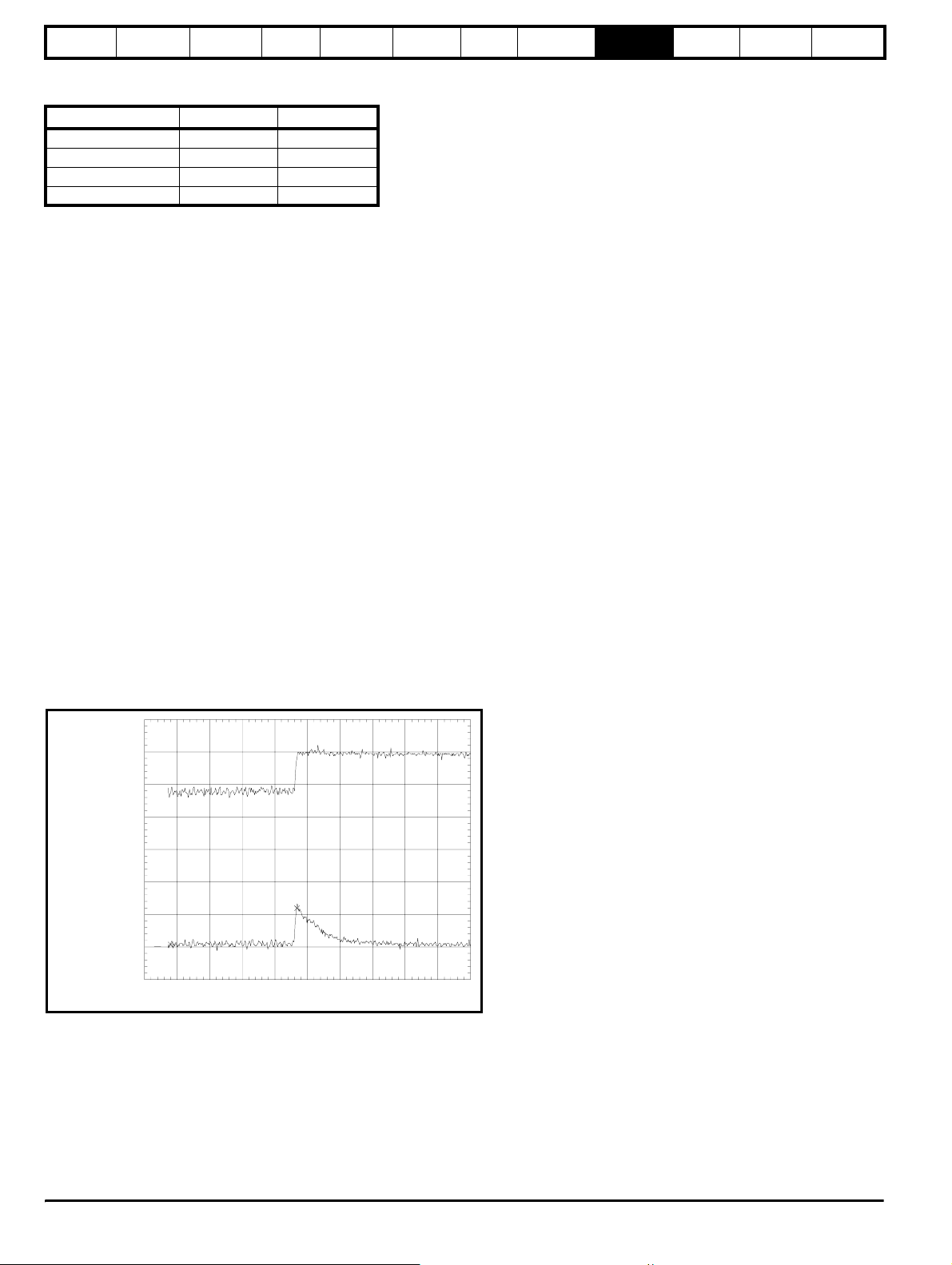
Safety
A
Information
Introduction
Product
information
System
design
Mechanical
installation
Electrical
installation
Getting
started
Optimisation
Parameters
Technical
data
Component
sizing
Diagnostics
There is one value of the scaling factor K for each drive voltage rating as shown in the table below.
Drive voltage rating Vfs K
200V 415V 2322
400V 830V 1161
575V 990V 973
690V 1190V 809
The integral gain Ki (Pr 4.14) is less critical and should be set so that
Ki = Kp x 256 x T / τ
m
where
is the time constant (L / R).
τ
m
R is the resistance of the supply for one phase.
Therefore
Ki = (K x L x Kc) x 256 x 167µs x R / L = 0.0427 x K x R x Kc
The above equations give the gain values that should give the best response at all switching frequencies with minimal overshoot. If required the gains
can be adjusted to improve performance as follows:
1. The integral gain (Ki) can be used to improve the performance of the current controllers by reducing the effects of inverter non-linearity. These
effects become more significant with higher switching frequency. These effects will more significant for drives with higher current ratings and
higher voltage ratings. If Ki is increased by a factor of 4 it is possible to get up to 10% overshoot in response to a step change of current
reference. For high performance applications, it is recommended that Ki is increased by a factor of 4 from the auto-tuned values. As the inverter
non-linearity is worse with higher switching frequencies it is may be necessary to increase Ki by a factor of 8 for operation with 16kHz switching
frequency.
2. It is possible to increase the proportional gain (Kp) to reduce the response time of the current controllers. If Kp is increased by a factor of 1.5 then
the response to a step change of reference will give 12.5% overshoot. It is recommended that Ki is increased in preference to Kp.
Setting the voltage controller gain
Even when the gains are set correctly there will be a transient change of DC Bus voltage when there is a change in the load on any drive connected
to the Regen unit. This can be reduced substantially by using an analogue input for power feed forward compensation (see Pr 3.10). The following
discussion relates to a system without power feed-forward compensation.
If the power flow from the supply is increased (i.e. more power is taken from the supply or less power is fed back into the supply) the DC Bus voltage
will fall, but the minimum level will be limited to just below the peak rectified level of the supply provided the maximum rating of the unit is not
exceeded. If the power flow from the supply is reduced (i.e. less power is taken from the supply or more power is fed back into the supply) the DC Bus
voltage will rise. During a rapid transient the bus will rise and then fall as shown below.
ch3: dT= 194ms dV=2.24 V
ctive regen
unit current
Regen unit
DC Bus
voltage
50mS/div
The example shown is for a very rapid load change where the torque reference of the motor drive has been changed instantly from one value to
another. The proportional gain of the voltage controller defines the voltage transient because the integral term is too slow to have an effect. (In
applications where the motor drive is operating under speed control, the speed controller may only require a limited rate of change of torque demand,
and so the transient voltage may be less than covered in the discussion below.) If the set point voltage (Pr 3.05) plus the transient rise exceed the
over-voltage trip level the Regen unit will trip.
When a 400V motor is operated above base speed from a drive in vector mode, fed from the Regen unit with the same rating supplying a DC voltage
of 700V, and an instantaneous change of torque is demanded (i.e. -100% to +100%) the peak of the voltage transient (∆V) is approximately 80V if the
current controllers are set up correctly and the voltage controller uses the default gain. (Operating with maximum voltage on the motor, i.e. above
base speed, gives the biggest transient of power and hence the biggest value of ∆V. )
98 Unidrive SP Regen Installation Guide
www.controltechniques.com Issue Number: 2
Page 99
Safety
Information
Introduction
Product
information
System
design
Mechanical
installation
Electrical
installation
Getting
started
Optimisation
Parameters
Te ch ni ca l
data
Component
sizing
Diagnostics
If the load change, drive voltage rating, motor voltage or DC Bus set-point are different then ∆V is calculated from:
X K
∆V = 80V x K
L
x KMV X KSP
RAT
Where:
= load change / 200%
K
L
= Drive voltage rating / 400
K
RAT
= motor voltage / 400
K
MV
K
= 700 / DC Bus voltage set point
SP
In some applications, particularly with a high d.c. bus voltage set point and low switching frequency it may be necessary to limit the rate of change of
power flow to prevent over voltage trips. A first order filter on the torque reference of the motor drive (i.e. using Pr 4.12) is the most effective method
to reduce the transient further. (A fixed limit of the rate of change of torque demand is less effective.) The following table gives an approximate
indication of the reduction in ∆V for different time constants. (As already mentioned the value of ∆V given if for an instantaneous change of torque
representing the worst case. In applications where a speed controller is used in the motor drive the transient will already include an inherent filter).
Time constant Change in ∆V
20mS x 0.75
40mS x 0.5
The transient produced is approximately proportional to the voltage controller gain. The default voltage controller gain is set to give a value that is
suitable for most applications. The gain may need to be increased if the DC Bus capacitance is high compared to two drives of similar rating coupled
together. However, care must be taken to ensure that the gain is not too high as this can cause excessive ripple in the DC Bus voltage.
3.07
Close start up contactor
Drive mode Regen
Coding
Bit SP FI DE Txt VM DP ND RA NC NV PT US RW BU PS
111
Update rate 4ms
When the Regen drive has powered-up through the soft-start and the DC Bus voltage has stopped rising and is higher than the contactor close
voltage this bit changes from 0 to 1. If the DC Bus voltage falls below the contactor open voltage DC or the system is synchronised and the AC
voltage falls below contactor open voltage AC this bit changes to zero. When regen mode is selected this bit is routed to the drive relay output
(Terminals 41/42) as default.
This output, or an alternative output, can be used to control the soft-start contactor.
Drive Rating
Vac
Contactor Close
Vdc
Contactor Open
Vdc
Contactor Open
Vac
200V 215 205 75
400V 430 410 150
575V 565 540 225
690V 565 540 225
3.08
Main contactor closed
Drive mode Regen
Coding
Bit SP FI DE Txt VM DP ND RA NC NV PT US RW BU PS
111
Default Regen 0
Update rate 4ms
When regen mode is selected Pr 3.08 is the destination for the digital input on terminal 25 (T25) as default. This input, or an alternative input, should
be connected to an auxiliary contact on the soft-start contactor so that it follows the state of the contactor. The Regen drive will only attempt to
synchronise to the supply when this parameter is one. This parameter is also used to monitor the contactor when the Regen drive is running. If at any
time this parameter is zero the Regen drive is immediately disabled.
3.09
Enable motor drive
Drive mode Regen
Coding
Bit SP FI DE Txt VM DP ND RA NC NV PT US RW BU PS
111
Update rate 4ms
When the unit has been enabled and successfully synchronised this bit will become active. If the Regen drive attempts to re-synchronise or trips, this
bit becomes inactive. When regen mode is selected this bit is routed to a the digital output on terminal 24 (T24) as default. The output, or an
alternative output, should be used to enable the motor drive(s) connected to the DC bus of the Regen drive.
Unidr ive SP Re gen Inst allatio n Guide 99
Issue Number: 2 www.controltechniques.com
Page 100
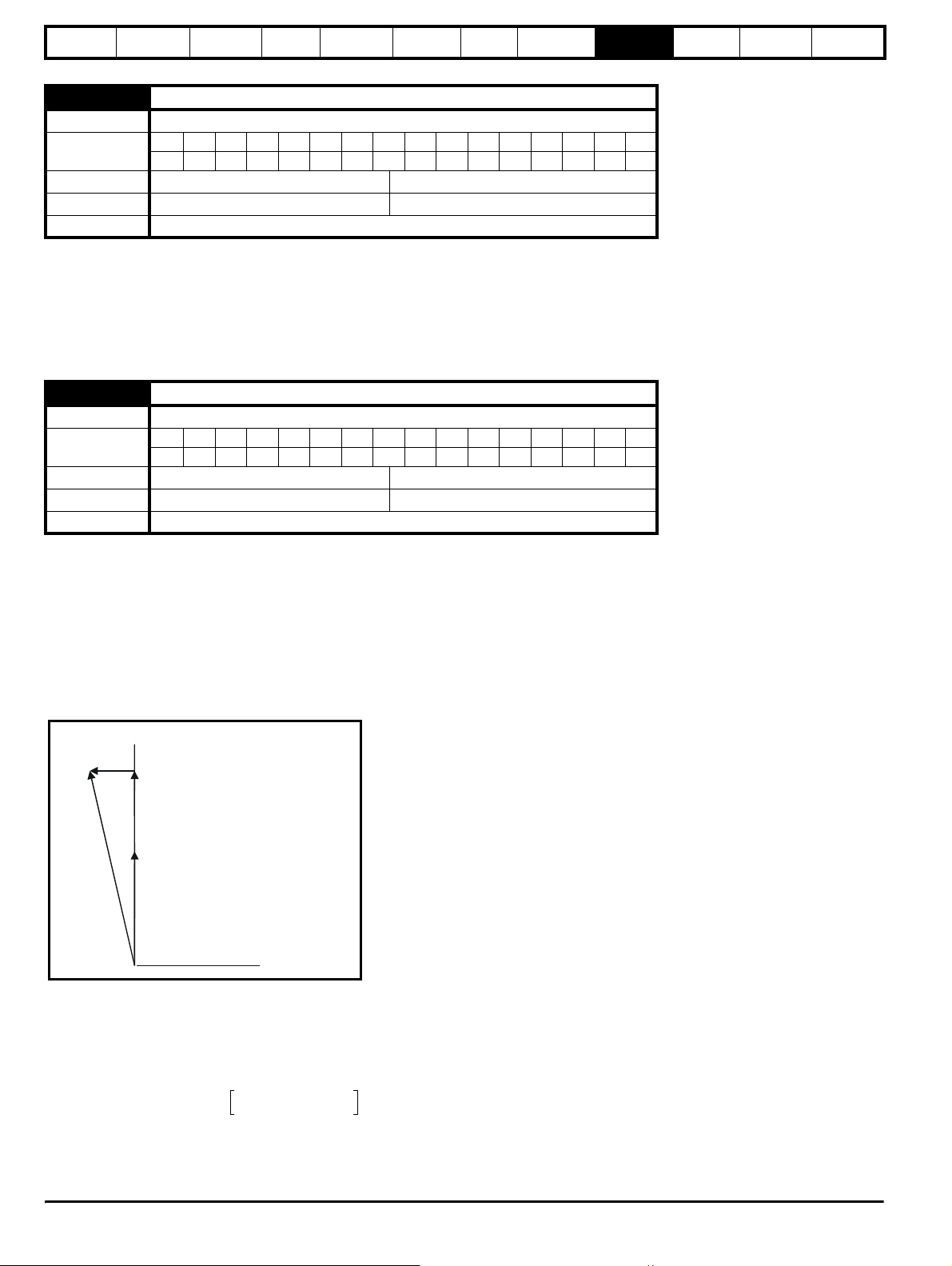
Safety
e
Information
Introduction
Product
information
System
design
Mechanical
installation
Electrical
installation
Getting
started
Optimisation
Parameters
Technical
data
Component
sizing
Diagnostics
3.10
Power feed-forward compensation
Drive mode Regen
Coding
Bit SP FI DE Txt VM DP ND RA NC NV PT US RW BU PS
12 1 1
Range Regen ±100 %
Default Regen 0.00
Update rate 4ms
Power feed-forward compensation can be used to reduce the transient DC bus voltage produced when a fast load transient occurs on drives
connected to the Regen drive. 100.0% power feed-forward is equivalent to an active current of Rated drive current / 0.45 (i.e. over current trip level)
and an AC terminal peak phase voltage equal to DC_VOLTAGE_MAX / 2. This scaling is the same as the power output from Pr 5.03 when high speed
output mode is used (see section 9.7 Menu 7: Analogue I/O ). Therefore an analogue output of the drive supplying the load and analogue input 2 or 3
of the drive acting as the supply Regen drive can be connected together to give power feed-forward compensation without further scaling if the two
drives are of equal rating. If the ratings are different the analogue input scaling must be used to give the correct power feed-forwards, where the
scaling is given by:
Load drive Rated drive current / Regen drive rated drive current
3.11
Current trimming mode
Drive mode Regen
Coding
Bit SP FI DE Txt VM DP ND RA NC NV PT US RW BU PS
111
Range Regen 0 to 1
Default Regen 0
Update rate 4ms read
This parameter defines the strategy used for current trimming in regen mode. If Pr 3.11=0 then current trimming is only carried out once after powerup. If Pr 3.11=1 current trimming is carried out after power-up and then before the drive runs each time it is enabled.
9.4 Menu 4: Current control
In Regen mode the drive operates in a reference frame that is aligned to the voltage at the drive terminals. Because the phase shift across the input
inductors is small, the reference frame is approximately aligned with the supply voltage. The maximum normal operating current is controlled by the
current limits.
DRIVE_CURRENT_MAX is used in calculating the maximum of some parameters and is fixed at 1.75 x rated drive current. The drive can operate up
to this level under normal conditions.
The relationship between the voltage and current for Regen mode operation is shown in the following vector diagram.
Regen mod
wLi
sy
vs
= Regen unit
terminal voltage
Supply
voltage
Definitions:
is = Regen drive terminal voltage vector
vs = Regen drive current vector
CURRENT_LIMIT_MAX is used as the maximum for some parameters such as the user current limits. The maximum current limit is defined as
follows (with a maximum of 1000%):
CURRENT_LIMIT_MAX
i
s
Maximum current
-------------------------------------------------------
Motor rated current
100%×=
Where:
Regen drive rated current is given by Pr 5.07
100 Unidrive SP Regen Installation Guide
www.controltechniques.com Issue Number: 2
 Loading...