

Page 1
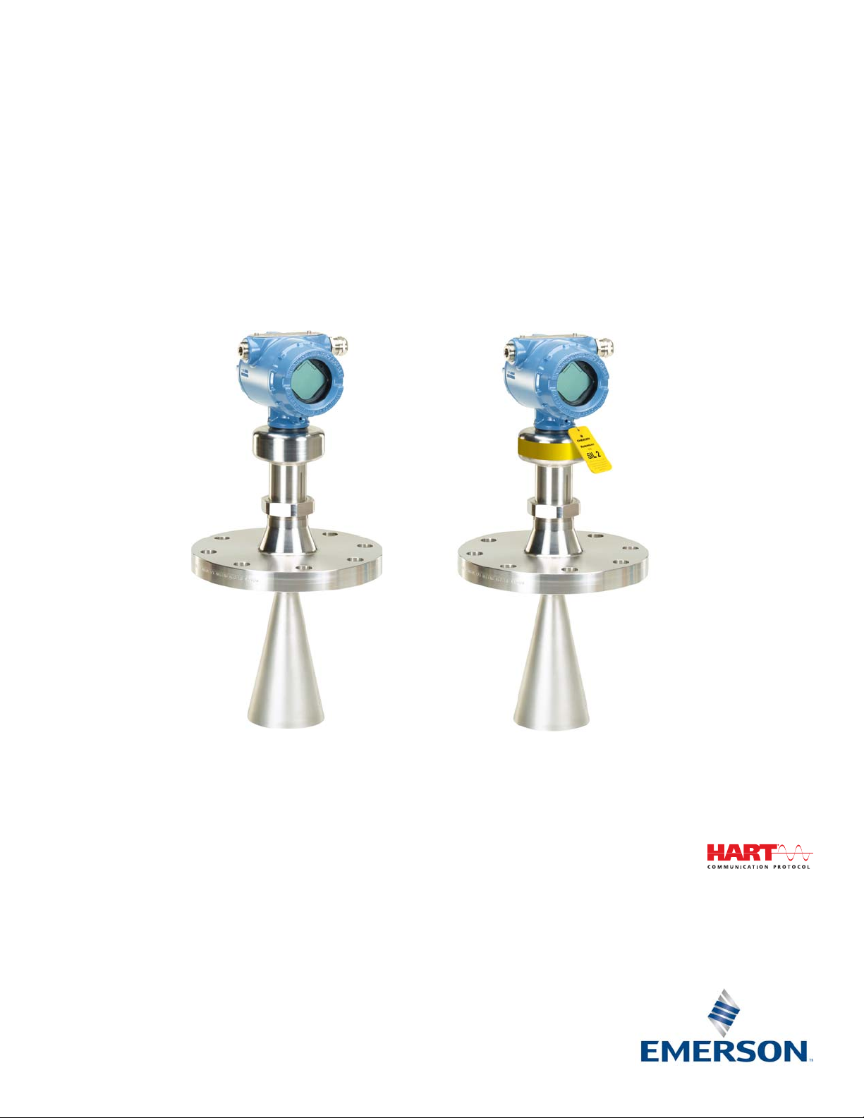
Rosemount™ 5408 and 5408:SIS Level Transmitters
Non-Contacting Radar
Reference Manual
00809-0100-4408, Rev BA
November 2017
Page 2

Page 3

Reference Manual
00809-0100-4408, Rev BA
Contents
1Section 1: Introduction
2Section 2: Transmitter Overview
Contents
November 2017
1.1 Using this manual . . . . . . . . . . . . . . . . . . . . . . . . . . . . . . . . . . . . . . . . . . . . . . . . . . . . . . . . . . . . . . . . . 1
1.2 Product recycling/disposal. . . . . . . . . . . . . . . . . . . . . . . . . . . . . . . . . . . . . . . . . . . . . . . . . . . . . . . . . . 1
2.1 Measurement principle. . . . . . . . . . . . . . . . . . . . . . . . . . . . . . . . . . . . . . . . . . . . . . . . . . . . . . . . . . . . . 3
2.2 Process characteristics . . . . . . . . . . . . . . . . . . . . . . . . . . . . . . . . . . . . . . . . . . . . . . . . . . . . . . . . . . . . . 4
2.2.1 Dielectric constant. . . . . . . . . . . . . . . . . . . . . . . . . . . . . . . . . . . . . . . . . . . . . . . . . . . . . . . . . . . 4
2.2.2 Foam and turbulence. . . . . . . . . . . . . . . . . . . . . . . . . . . . . . . . . . . . . . . . . . . . . . . . . . . . . . . . . 4
2.2.3 Condensation . . . . . . . . . . . . . . . . . . . . . . . . . . . . . . . . . . . . . . . . . . . . . . . . . . . . . . . . . . . . . . . 5
2.2.4 Dust. . . . . . . . . . . . . . . . . . . . . . . . . . . . . . . . . . . . . . . . . . . . . . . . . . . . . . . . . . . . . . . . . . . . . . . . 5
2.2.5 Solid surface . . . . . . . . . . . . . . . . . . . . . . . . . . . . . . . . . . . . . . . . . . . . . . . . . . . . . . . . . . . . . . . . 5
2.3 Vessel characteristics . . . . . . . . . . . . . . . . . . . . . . . . . . . . . . . . . . . . . . . . . . . . . . . . . . . . . . . . . . . . . . 6
2.3.1 In-tank obstructions. . . . . . . . . . . . . . . . . . . . . . . . . . . . . . . . . . . . . . . . . . . . . . . . . . . . . . . . . . 6
2.3.2 Tank shape. . . . . . . . . . . . . . . . . . . . . . . . . . . . . . . . . . . . . . . . . . . . . . . . . . . . . . . . . . . . . . . . . . 6
2.4 Application examples . . . . . . . . . . . . . . . . . . . . . . . . . . . . . . . . . . . . . . . . . . . . . . . . . . . . . . . . . . . . . . 6
2.5 Components of the transmitter . . . . . . . . . . . . . . . . . . . . . . . . . . . . . . . . . . . . . . . . . . . . . . . . . . . . . 9
2.6 System integration . . . . . . . . . . . . . . . . . . . . . . . . . . . . . . . . . . . . . . . . . . . . . . . . . . . . . . . . . . . . . . . 10
3Section 3: Mechanical Installation
3.1 Safety messages. . . . . . . . . . . . . . . . . . . . . . . . . . . . . . . . . . . . . . . . . . . . . . . . . . . . . . . . . . . . . . . . . . 11
3.2 Confirm approval type . . . . . . . . . . . . . . . . . . . . . . . . . . . . . . . . . . . . . . . . . . . . . . . . . . . . . . . . . . . . 12
3.3 Review mounting considerations . . . . . . . . . . . . . . . . . . . . . . . . . . . . . . . . . . . . . . . . . . . . . . . . . . . 12
3.3.1 Mounting position . . . . . . . . . . . . . . . . . . . . . . . . . . . . . . . . . . . . . . . . . . . . . . . . . . . . . . . . . . 12
3.3.2 Free space requirements. . . . . . . . . . . . . . . . . . . . . . . . . . . . . . . . . . . . . . . . . . . . . . . . . . . . . 13
3.3.3 Antenna size . . . . . . . . . . . . . . . . . . . . . . . . . . . . . . . . . . . . . . . . . . . . . . . . . . . . . . . . . . . . . . . 14
3.3.4 Antenna inclination . . . . . . . . . . . . . . . . . . . . . . . . . . . . . . . . . . . . . . . . . . . . . . . . . . . . . . . . . 14
3.3.5 Non-metallic tanks . . . . . . . . . . . . . . . . . . . . . . . . . . . . . . . . . . . . . . . . . . . . . . . . . . . . . . . . . . 14
3.3.6 Beam width and beam angle . . . . . . . . . . . . . . . . . . . . . . . . . . . . . . . . . . . . . . . . . . . . . . . . . 15
3.3.7 Nozzle requirements . . . . . . . . . . . . . . . . . . . . . . . . . . . . . . . . . . . . . . . . . . . . . . . . . . . . . . . . 16
3.3.8 Still pipe/chamber installations . . . . . . . . . . . . . . . . . . . . . . . . . . . . . . . . . . . . . . . . . . . . . . . 19
3.3.9 Ball valve installation . . . . . . . . . . . . . . . . . . . . . . . . . . . . . . . . . . . . . . . . . . . . . . . . . . . . . . . . 20
3.4 Review mounting preparations. . . . . . . . . . . . . . . . . . . . . . . . . . . . . . . . . . . . . . . . . . . . . . . . . . . . . 21
Contents
3.4.1 Assemble the segmented cone antenna . . . . . . . . . . . . . . . . . . . . . . . . . . . . . . . . . . . . . . . 21
iii
Page 4

Contents
November 2017
Reference Manual
00809-0100-4408, Rev BA
3.4.2 Shorten the extended cone antenna . . . . . . . . . . . . . . . . . . . . . . . . . . . . . . . . . . . . . . . . . . 23
3.5 Mount the cone antenna . . . . . . . . . . . . . . . . . . . . . . . . . . . . . . . . . . . . . . . . . . . . . . . . . . . . . . . . . . 24
3.5.1 Flanged version . . . . . . . . . . . . . . . . . . . . . . . . . . . . . . . . . . . . . . . . . . . . . . . . . . . . . . . . . . . . . 25
3.5.2 Flanged version with air purge ring (option code PC1) . . . . . . . . . . . . . . . . . . . . . . . . . . . 26
3.5.3 Threaded version . . . . . . . . . . . . . . . . . . . . . . . . . . . . . . . . . . . . . . . . . . . . . . . . . . . . . . . . . . . 28
3.5.4 Bracket mounting. . . . . . . . . . . . . . . . . . . . . . . . . . . . . . . . . . . . . . . . . . . . . . . . . . . . . . . . . . . 34
3.5.5 Align transmitter head. . . . . . . . . . . . . . . . . . . . . . . . . . . . . . . . . . . . . . . . . . . . . . . . . . . . . . . 37
3.6 Mount the process seal antenna . . . . . . . . . . . . . . . . . . . . . . . . . . . . . . . . . . . . . . . . . . . . . . . . . . . . 39
3.6.1 Flanged version . . . . . . . . . . . . . . . . . . . . . . . . . . . . . . . . . . . . . . . . . . . . . . . . . . . . . . . . . . . . . 39
3.6.2 Tri Clamp version . . . . . . . . . . . . . . . . . . . . . . . . . . . . . . . . . . . . . . . . . . . . . . . . . . . . . . . . . . . 41
3.7 Mount the parabolic antenna . . . . . . . . . . . . . . . . . . . . . . . . . . . . . . . . . . . . . . . . . . . . . . . . . . . . . . 42
3.7.1 Flanged version . . . . . . . . . . . . . . . . . . . . . . . . . . . . . . . . . . . . . . . . . . . . . . . . . . . . . . . . . . . . . 43
3.7.2 Threaded version . . . . . . . . . . . . . . . . . . . . . . . . . . . . . . . . . . . . . . . . . . . . . . . . . . . . . . . . . . . 44
3.7.3 Welded version. . . . . . . . . . . . . . . . . . . . . . . . . . . . . . . . . . . . . . . . . . . . . . . . . . . . . . . . . . . . . 48
3.7.4 Adjust the inclination of the antenna . . . . . . . . . . . . . . . . . . . . . . . . . . . . . . . . . . . . . . . . . . 53
3.7.5 Connect the air purging . . . . . . . . . . . . . . . . . . . . . . . . . . . . . . . . . . . . . . . . . . . . . . . . . . . . . 56
3.8 Adjust display orientation (optional) . . . . . . . . . . . . . . . . . . . . . . . . . . . . . . . . . . . . . . . . . . . . . . . . 57
4Section 4: Electrical Installation
4.1 Safety messages. . . . . . . . . . . . . . . . . . . . . . . . . . . . . . . . . . . . . . . . . . . . . . . . . . . . . . . . . . . . . . . . . . 59
4.2 Cable selection . . . . . . . . . . . . . . . . . . . . . . . . . . . . . . . . . . . . . . . . . . . . . . . . . . . . . . . . . . . . . . . . . . . 60
4.3 Cable gland/conduit . . . . . . . . . . . . . . . . . . . . . . . . . . . . . . . . . . . . . . . . . . . . . . . . . . . . . . . . . . . . . . 60
4.4 Power supply . . . . . . . . . . . . . . . . . . . . . . . . . . . . . . . . . . . . . . . . . . . . . . . . . . . . . . . . . . . . . . . . . . . . 60
4.5 Hazardous areas. . . . . . . . . . . . . . . . . . . . . . . . . . . . . . . . . . . . . . . . . . . . . . . . . . . . . . . . . . . . . . . . . . 60
4.6 Wiring diagram . . . . . . . . . . . . . . . . . . . . . . . . . . . . . . . . . . . . . . . . . . . . . . . . . . . . . . . . . . . . . . . . . . 61
4.7 Grounding. . . . . . . . . . . . . . . . . . . . . . . . . . . . . . . . . . . . . . . . . . . . . . . . . . . . . . . . . . . . . . . . . . . . . . . 62
4.7.1 Transmitter housing . . . . . . . . . . . . . . . . . . . . . . . . . . . . . . . . . . . . . . . . . . . . . . . . . . . . . . . . 62
4.7.2 Signal cable shield grounding . . . . . . . . . . . . . . . . . . . . . . . . . . . . . . . . . . . . . . . . . . . . . . . . 62
4.8 Wiring and power up. . . . . . . . . . . . . . . . . . . . . . . . . . . . . . . . . . . . . . . . . . . . . . . . . . . . . . . . . . . . . . 63
4.9 Optional devices . . . . . . . . . . . . . . . . . . . . . . . . . . . . . . . . . . . . . . . . . . . . . . . . . . . . . . . . . . . . . . . . . 66
4.9.1 Rosemount
™
333 HART Tri-Loop™ . . . . . . . . . . . . . . . . . . . . . . . . . . . . . . . . . . . . . . . . . . . . 66
5Section 5: Configuration
5.1 Safety messages. . . . . . . . . . . . . . . . . . . . . . . . . . . . . . . . . . . . . . . . . . . . . . . . . . . . . . . . . . . . . . . . . . 67
5.2 Overview . . . . . . . . . . . . . . . . . . . . . . . . . . . . . . . . . . . . . . . . . . . . . . . . . . . . . . . . . . . . . . . . . . . . . . . . 67
5.3 System readiness . . . . . . . . . . . . . . . . . . . . . . . . . . . . . . . . . . . . . . . . . . . . . . . . . . . . . . . . . . . . . . . . . 68
5.3.1 Confirm correct device driver. . . . . . . . . . . . . . . . . . . . . . . . . . . . . . . . . . . . . . . . . . . . . . . . . 68
5.4 Get started with your preferred configuration tool. . . . . . . . . . . . . . . . . . . . . . . . . . . . . . . . . . . . 68
iv
Contents
Page 5

Reference Manual
00809-0100-4408, Rev BA
6Section 6: Operation
Contents
November 2017
5.4.1 Rosemount Radar Master Plus . . . . . . . . . . . . . . . . . . . . . . . . . . . . . . . . . . . . . . . . . . . . . . . . 68
5.4.2 AMS Device Manager. . . . . . . . . . . . . . . . . . . . . . . . . . . . . . . . . . . . . . . . . . . . . . . . . . . . . . . . 69
5.4.3 Field Communicator . . . . . . . . . . . . . . . . . . . . . . . . . . . . . . . . . . . . . . . . . . . . . . . . . . . . . . . . 70
5.5 Confirm HART revision capability . . . . . . . . . . . . . . . . . . . . . . . . . . . . . . . . . . . . . . . . . . . . . . . . . . . 70
5.5.1 Switch HART revision mode . . . . . . . . . . . . . . . . . . . . . . . . . . . . . . . . . . . . . . . . . . . . . . . . . . 70
5.6 Configure device using Guided Setup . . . . . . . . . . . . . . . . . . . . . . . . . . . . . . . . . . . . . . . . . . . . . . . 71
5.7 Verify Level . . . . . . . . . . . . . . . . . . . . . . . . . . . . . . . . . . . . . . . . . . . . . . . . . . . . . . . . . . . . . . . . . . . . . . 72
5.8 Establish multidrop communication . . . . . . . . . . . . . . . . . . . . . . . . . . . . . . . . . . . . . . . . . . . . . . . . 73
5.9 Use with the Rosemount 333 HART Tri-Loop
6.1 LCD display screen messages . . . . . . . . . . . . . . . . . . . . . . . . . . . . . . . . . . . . . . . . . . . . . . . . . . . . . . 75
6.1.1 Startup screen sequence. . . . . . . . . . . . . . . . . . . . . . . . . . . . . . . . . . . . . . . . . . . . . . . . . . . . . 75
6.1.2 Variable screens . . . . . . . . . . . . . . . . . . . . . . . . . . . . . . . . . . . . . . . . . . . . . . . . . . . . . . . . . . . . 76
™
. . . . . . . . . . . . . . . . . . . . . . . . . . . . . . . . . . . . . . . . 74
6.2 Set up the LCD display. . . . . . . . . . . . . . . . . . . . . . . . . . . . . . . . . . . . . . . . . . . . . . . . . . . . . . . . . . . . . 76
6.3 View measurement data . . . . . . . . . . . . . . . . . . . . . . . . . . . . . . . . . . . . . . . . . . . . . . . . . . . . . . . . . . 77
6.3.1 View current measurement values . . . . . . . . . . . . . . . . . . . . . . . . . . . . . . . . . . . . . . . . . . . . 77
6.3.2 Interpret measurement status . . . . . . . . . . . . . . . . . . . . . . . . . . . . . . . . . . . . . . . . . . . . . . . . 78
6.4 Check device status. . . . . . . . . . . . . . . . . . . . . . . . . . . . . . . . . . . . . . . . . . . . . . . . . . . . . . . . . . . . . . . 78
7Section 7: Service and Troubleshooting
7.1 Safety messages. . . . . . . . . . . . . . . . . . . . . . . . . . . . . . . . . . . . . . . . . . . . . . . . . . . . . . . . . . . . . . . . . . 81
7.2 Diagnostic messages. . . . . . . . . . . . . . . . . . . . . . . . . . . . . . . . . . . . . . . . . . . . . . . . . . . . . . . . . . . . . . 82
7.3 Troubleshooting guide . . . . . . . . . . . . . . . . . . . . . . . . . . . . . . . . . . . . . . . . . . . . . . . . . . . . . . . . . . . . 87
7.4 Service and troubleshooting tools . . . . . . . . . . . . . . . . . . . . . . . . . . . . . . . . . . . . . . . . . . . . . . . . . . 92
7.4.1 Use the echo curve. . . . . . . . . . . . . . . . . . . . . . . . . . . . . . . . . . . . . . . . . . . . . . . . . . . . . . . . . . 92
7.4.2 Manage disturbance echoes. . . . . . . . . . . . . . . . . . . . . . . . . . . . . . . . . . . . . . . . . . . . . . . . . . 95
7.4.3 Perform an analog loop test . . . . . . . . . . . . . . . . . . . . . . . . . . . . . . . . . . . . . . . . . . . . . . . . . 100
7.4.4 Use the TEST terminal . . . . . . . . . . . . . . . . . . . . . . . . . . . . . . . . . . . . . . . . . . . . . . . . . . . . . . 101
7.4.5 Calibrate analog out. . . . . . . . . . . . . . . . . . . . . . . . . . . . . . . . . . . . . . . . . . . . . . . . . . . . . . . . 102
7.4.6 Save and load configuration files. . . . . . . . . . . . . . . . . . . . . . . . . . . . . . . . . . . . . . . . . . . . . 103
7.4.7 Restore to default settings . . . . . . . . . . . . . . . . . . . . . . . . . . . . . . . . . . . . . . . . . . . . . . . . . . 103
7.4.8 Use the simulation mode . . . . . . . . . . . . . . . . . . . . . . . . . . . . . . . . . . . . . . . . . . . . . . . . . . . 104
7.4.9 View input registers . . . . . . . . . . . . . . . . . . . . . . . . . . . . . . . . . . . . . . . . . . . . . . . . . . . . . . . . 104
Contents
7.4.10View/edit holding registers . . . . . . . . . . . . . . . . . . . . . . . . . . . . . . . . . . . . . . . . . . . . . . . . . 104
7.5 Write protect a transmitter . . . . . . . . . . . . . . . . . . . . . . . . . . . . . . . . . . . . . . . . . . . . . . . . . . . . . . . 105
7.6 Application challenges . . . . . . . . . . . . . . . . . . . . . . . . . . . . . . . . . . . . . . . . . . . . . . . . . . . . . . . . . . . 106
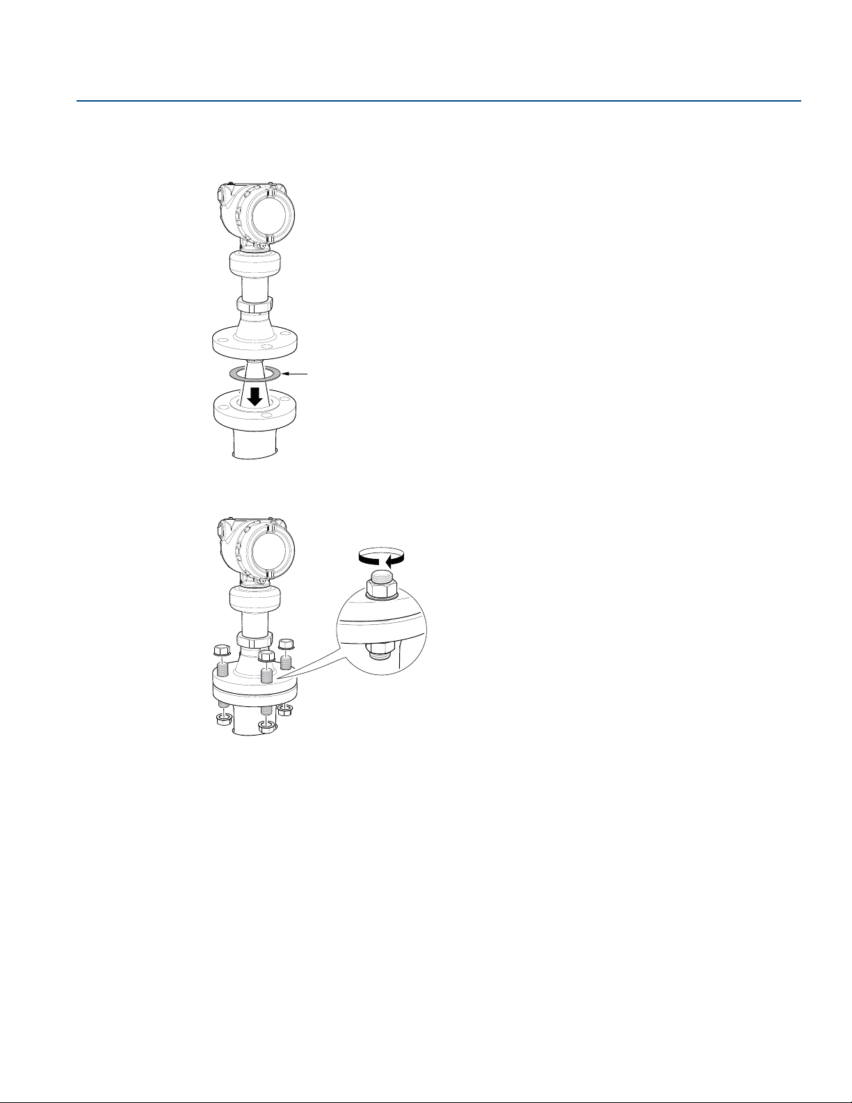
7.6.1 Handling disturbances at top of tank . . . . . . . . . . . . . . . . . . . . . . . . . . . . . . . . . . . . . . . . . 106
v
Page 6

Contents
November 2017
Reference Manual
00809-0100-4408, Rev BA
7.6.2 Tracking of weak surface echoes close to tank bottom . . . . . . . . . . . . . . . . . . . . . . . . . 108
7.6.3 Handling ghost echoes in still pipes . . . . . . . . . . . . . . . . . . . . . . . . . . . . . . . . . . . . . . . . . . 110
7.6.4 Handling strong double bounce echoes . . . . . . . . . . . . . . . . . . . . . . . . . . . . . . . . . . . . . . 111
7.7 Transmitter head replacement . . . . . . . . . . . . . . . . . . . . . . . . . . . . . . . . . . . . . . . . . . . . . . . . . . . . 112
7.8 Cleaning or replacing the PTFE sealing . . . . . . . . . . . . . . . . . . . . . . . . . . . . . . . . . . . . . . . . . . . . . 115
7.8.1 Remove from service. . . . . . . . . . . . . . . . . . . . . . . . . . . . . . . . . . . . . . . . . . . . . . . . . . . . . . . 115
7.8.2 Cleaning . . . . . . . . . . . . . . . . . . . . . . . . . . . . . . . . . . . . . . . . . . . . . . . . . . . . . . . . . . . . . . . . . . 115
7.8.3 Replacing . . . . . . . . . . . . . . . . . . . . . . . . . . . . . . . . . . . . . . . . . . . . . . . . . . . . . . . . . . . . . . . . . 115
7.9 Service support. . . . . . . . . . . . . . . . . . . . . . . . . . . . . . . . . . . . . . . . . . . . . . . . . . . . . . . . . . . . . . . . . . 119
8Section 8: Safety Instrumented Systems (4-20 mA only)
8.1 Safety messages. . . . . . . . . . . . . . . . . . . . . . . . . . . . . . . . . . . . . . . . . . . . . . . . . . . . . . . . . . . . . . . . . 121
8.2 Terms and definitions . . . . . . . . . . . . . . . . . . . . . . . . . . . . . . . . . . . . . . . . . . . . . . . . . . . . . . . . . . . . 122
8.3 Safety Instrumented System (SIS) certification . . . . . . . . . . . . . . . . . . . . . . . . . . . . . . . . . . . . . . 124
8.4 Safety certified identification . . . . . . . . . . . . . . . . . . . . . . . . . . . . . . . . . . . . . . . . . . . . . . . . . . . . . 125
8.5 Installation . . . . . . . . . . . . . . . . . . . . . . . . . . . . . . . . . . . . . . . . . . . . . . . . . . . . . . . . . . . . . . . . . . . . . 126
8.5.1 Measuring range. . . . . . . . . . . . . . . . . . . . . . . . . . . . . . . . . . . . . . . . . . . . . . . . . . . . . . . . . . . 126
8.6 Configuration . . . . . . . . . . . . . . . . . . . . . . . . . . . . . . . . . . . . . . . . . . . . . . . . . . . . . . . . . . . . . . . . . . . 126
8.6.1 Prerequisites . . . . . . . . . . . . . . . . . . . . . . . . . . . . . . . . . . . . . . . . . . . . . . . . . . . . . . . . . . . . . . 126
8.6.2 Configure device using Guided Setup . . . . . . . . . . . . . . . . . . . . . . . . . . . . . . . . . . . . . . . . 126
8.6.3 Set operational mode . . . . . . . . . . . . . . . . . . . . . . . . . . . . . . . . . . . . . . . . . . . . . . . . . . . . . . 126
8.6.4 Enable safety mode . . . . . . . . . . . . . . . . . . . . . . . . . . . . . . . . . . . . . . . . . . . . . . . . . . . . . . . . 127
8.6.5 Alarm and saturation levels . . . . . . . . . . . . . . . . . . . . . . . . . . . . . . . . . . . . . . . . . . . . . . . . . 128
8.7 Site acceptance . . . . . . . . . . . . . . . . . . . . . . . . . . . . . . . . . . . . . . . . . . . . . . . . . . . . . . . . . . . . . . . . . 128
8.8 Proof-testing. . . . . . . . . . . . . . . . . . . . . . . . . . . . . . . . . . . . . . . . . . . . . . . . . . . . . . . . . . . . . . . . . . . . 128
8.8.1 Overview . . . . . . . . . . . . . . . . . . . . . . . . . . . . . . . . . . . . . . . . . . . . . . . . . . . . . . . . . . . . . . . . . 128
8.8.2 1-point level and analog output verification . . . . . . . . . . . . . . . . . . . . . . . . . . . . . . . . . . . 130
8.8.3 2-point level and analog output verification . . . . . . . . . . . . . . . . . . . . . . . . . . . . . . . . . . . 131
8.8.4 Analog output verification . . . . . . . . . . . . . . . . . . . . . . . . . . . . . . . . . . . . . . . . . . . . . . . . . . 132
8.8.5 Level deviation monitoring. . . . . . . . . . . . . . . . . . . . . . . . . . . . . . . . . . . . . . . . . . . . . . . . . . 133
8.8.6 Product repair . . . . . . . . . . . . . . . . . . . . . . . . . . . . . . . . . . . . . . . . . . . . . . . . . . . . . . . . . . . . . 133
8.9 Specifications . . . . . . . . . . . . . . . . . . . . . . . . . . . . . . . . . . . . . . . . . . . . . . . . . . . . . . . . . . . . . . . . . . . 133
AAppendix A: Specifications and Reference Data
A.1 Performance specifications . . . . . . . . . . . . . . . . . . . . . . . . . . . . . . . . . . . . . . . . . . . . . . . . . . . . . . . 135
A.1.1 General . . . . . . . . . . . . . . . . . . . . . . . . . . . . . . . . . . . . . . . . . . . . . . . . . . . . . . . . . . . . . . . . . . . 135
A.1.2 Measuring range. . . . . . . . . . . . . . . . . . . . . . . . . . . . . . . . . . . . . . . . . . . . . . . . . . . . . . . . . . . 135
A.1.3 Environment . . . . . . . . . . . . . . . . . . . . . . . . . . . . . . . . . . . . . . . . . . . . . . . . . . . . . . . . . . . . . . 137
vi
Contents
Page 7

Reference Manual
00809-0100-4408, Rev BA
Contents
November 2017
A.2 Functional specifications . . . . . . . . . . . . . . . . . . . . . . . . . . . . . . . . . . . . . . . . . . . . . . . . . . . . . . . . . 137
A.2.1 General . . . . . . . . . . . . . . . . . . . . . . . . . . . . . . . . . . . . . . . . . . . . . . . . . . . . . . . . . . . . . . . . . . . 137
A.2.2 Display and configuration. . . . . . . . . . . . . . . . . . . . . . . . . . . . . . . . . . . . . . . . . . . . . . . . . . . 137
A.2.3 4-20 mA HART. . . . . . . . . . . . . . . . . . . . . . . . . . . . . . . . . . . . . . . . . . . . . . . . . . . . . . . . . . . . . 138
A.2.4 Diagnostics . . . . . . . . . . . . . . . . . . . . . . . . . . . . . . . . . . . . . . . . . . . . . . . . . . . . . . . . . . . . . . . 139
A.2.5 Process temperature and pressure rating . . . . . . . . . . . . . . . . . . . . . . . . . . . . . . . . . . . . . 140
A.2.6 Temperature limits. . . . . . . . . . . . . . . . . . . . . . . . . . . . . . . . . . . . . . . . . . . . . . . . . . . . . . . . . 141
A.2.7 Flange rating . . . . . . . . . . . . . . . . . . . . . . . . . . . . . . . . . . . . . . . . . . . . . . . . . . . . . . . . . . . . . . 141
A.2.8 Conditions used for flange strength calculations. . . . . . . . . . . . . . . . . . . . . . . . . . . . . . . 141
A.2.9 Air purging. . . . . . . . . . . . . . . . . . . . . . . . . . . . . . . . . . . . . . . . . . . . . . . . . . . . . . . . . . . . . . . . 141
A.2.10System integration . . . . . . . . . . . . . . . . . . . . . . . . . . . . . . . . . . . . . . . . . . . . . . . . . . . . . . . . 142
A.3 Physical specifications. . . . . . . . . . . . . . . . . . . . . . . . . . . . . . . . . . . . . . . . . . . . . . . . . . . . . . . . . . . . 142
A.3.1 Material selection . . . . . . . . . . . . . . . . . . . . . . . . . . . . . . . . . . . . . . . . . . . . . . . . . . . . . . . . . . 142
A.3.2 Engineered solutions . . . . . . . . . . . . . . . . . . . . . . . . . . . . . . . . . . . . . . . . . . . . . . . . . . . . . . . 142
A.3.3 Housing and enclosure . . . . . . . . . . . . . . . . . . . . . . . . . . . . . . . . . . . . . . . . . . . . . . . . . . . . . 142
A.3.4 Tank connection . . . . . . . . . . . . . . . . . . . . . . . . . . . . . . . . . . . . . . . . . . . . . . . . . . . . . . . . . . . 143
A.3.5 Flange dimensions . . . . . . . . . . . . . . . . . . . . . . . . . . . . . . . . . . . . . . . . . . . . . . . . . . . . . . . . . 143
A.3.6 Antenna versions . . . . . . . . . . . . . . . . . . . . . . . . . . . . . . . . . . . . . . . . . . . . . . . . . . . . . . . . . . 143
A.3.7 Material exposed to tank atmosphere . . . . . . . . . . . . . . . . . . . . . . . . . . . . . . . . . . . . . . . . 143
A.4 Ordering information . . . . . . . . . . . . . . . . . . . . . . . . . . . . . . . . . . . . . . . . . . . . . . . . . . . . . . . . . . . . 144
A.5 Spare parts and accessories. . . . . . . . . . . . . . . . . . . . . . . . . . . . . . . . . . . . . . . . . . . . . . . . . . . . . . . 155
A.6 Dimensional drawings . . . . . . . . . . . . . . . . . . . . . . . . . . . . . . . . . . . . . . . . . . . . . . . . . . . . . . . . . . . 163
A.6.1 Standard flanges. . . . . . . . . . . . . . . . . . . . . . . . . . . . . . . . . . . . . . . . . . . . . . . . . . . . . . . . . . . 167
BAppendix B: Product Certifications
B.1 European directive information . . . . . . . . . . . . . . . . . . . . . . . . . . . . . . . . . . . . . . . . . . . . . . . . . . . 169
B.2 Safety Instrumented Systems (SIS). . . . . . . . . . . . . . . . . . . . . . . . . . . . . . . . . . . . . . . . . . . . . . . . . 169
B.3 Telecommunication compliance . . . . . . . . . . . . . . . . . . . . . . . . . . . . . . . . . . . . . . . . . . . . . . . . . . 169
B.4 FCC . . . . . . . . . . . . . . . . . . . . . . . . . . . . . . . . . . . . . . . . . . . . . . . . . . . . . . . . . . . . . . . . . . . . . . . . . . . . 169
B.5 IC. . . . . . . . . . . . . . . . . . . . . . . . . . . . . . . . . . . . . . . . . . . . . . . . . . . . . . . . . . . . . . . . . . . . . . . . . . . . . . 170
B.6 Radio Equipment Directive (RED) 2014/53/EU . . . . . . . . . . . . . . . . . . . . . . . . . . . . . . . . . . . . . . 170
B.7 Installing Equipment in North America . . . . . . . . . . . . . . . . . . . . . . . . . . . . . . . . . . . . . . . . . . . . . 170
B.8 U.S.A. . . . . . . . . . . . . . . . . . . . . . . . . . . . . . . . . . . . . . . . . . . . . . . . . . . . . . . . . . . . . . . . . . . . . . . . . . . 170
B.9 Canada. . . . . . . . . . . . . . . . . . . . . . . . . . . . . . . . . . . . . . . . . . . . . . . . . . . . . . . . . . . . . . . . . . . . . . . . . 172
Contents
B.10Europe . . . . . . . . . . . . . . . . . . . . . . . . . . . . . . . . . . . . . . . . . . . . . . . . . . . . . . . . . . . . . . . . . . . . . . . . . 174
B.11International. . . . . . . . . . . . . . . . . . . . . . . . . . . . . . . . . . . . . . . . . . . . . . . . . . . . . . . . . . . . . . . . . . . . 176
B.12Brazil . . . . . . . . . . . . . . . . . . . . . . . . . . . . . . . . . . . . . . . . . . . . . . . . . . . . . . . . . . . . . . . . . . . . . . . . . . 177
B.13China . . . . . . . . . . . . . . . . . . . . . . . . . . . . . . . . . . . . . . . . . . . . . . . . . . . . . . . . . . . . . . . . . . . . . . . . . . 177
vii
Page 8

Contents
November 2017
B.14Republic of Korea . . . . . . . . . . . . . . . . . . . . . . . . . . . . . . . . . . . . . . . . . . . . . . . . . . . . . . . . . . . . . . . 178
B.15Additional certifications. . . . . . . . . . . . . . . . . . . . . . . . . . . . . . . . . . . . . . . . . . . . . . . . . . . . . . . . . . 178
B.16Installation drawings . . . . . . . . . . . . . . . . . . . . . . . . . . . . . . . . . . . . . . . . . . . . . . . . . . . . . . . . . . . . 178
CAppendix C: Configuration Parameters
C.1 Menu tree . . . . . . . . . . . . . . . . . . . . . . . . . . . . . . . . . . . . . . . . . . . . . . . . . . . . . . . . . . . . . . . . . . . . . . 185
C.2 Device setup . . . . . . . . . . . . . . . . . . . . . . . . . . . . . . . . . . . . . . . . . . . . . . . . . . . . . . . . . . . . . . . . . . . . 187
C.2.1 HART
C.2.2 Units . . . . . . . . . . . . . . . . . . . . . . . . . . . . . . . . . . . . . . . . . . . . . . . . . . . . . . . . . . . . . . . . . . . . . 187
C.2.3 Analog output . . . . . . . . . . . . . . . . . . . . . . . . . . . . . . . . . . . . . . . . . . . . . . . . . . . . . . . . . . . . . 187
C.2.4 Display . . . . . . . . . . . . . . . . . . . . . . . . . . . . . . . . . . . . . . . . . . . . . . . . . . . . . . . . . . . . . . . . . . . 188
C.2.5 Security . . . . . . . . . . . . . . . . . . . . . . . . . . . . . . . . . . . . . . . . . . . . . . . . . . . . . . . . . . . . . . . . . . 189
C.2.6 Device Information . . . . . . . . . . . . . . . . . . . . . . . . . . . . . . . . . . . . . . . . . . . . . . . . . . . . . . . . 189
C.3 Level setup . . . . . . . . . . . . . . . . . . . . . . . . . . . . . . . . . . . . . . . . . . . . . . . . . . . . . . . . . . . . . . . . . . . . . 189
®
protocol . . . . . . . . . . . . . . . . . . . . . . . . . . . . . . . . . . . . . . . . . . . . . . . . . . . . . . . . . . . 187
Reference Manual
00809-0100-4408, Rev BA
C.3.1 Geometry. . . . . . . . . . . . . . . . . . . . . . . . . . . . . . . . . . . . . . . . . . . . . . . . . . . . . . . . . . . . . . . . . 189
C.3.2 Environment . . . . . . . . . . . . . . . . . . . . . . . . . . . . . . . . . . . . . . . . . . . . . . . . . . . . . . . . . . . . . . 196
C.3.3 Volume. . . . . . . . . . . . . . . . . . . . . . . . . . . . . . . . . . . . . . . . . . . . . . . . . . . . . . . . . . . . . . . . . . . 196
C.3.4 Scaled variable . . . . . . . . . . . . . . . . . . . . . . . . . . . . . . . . . . . . . . . . . . . . . . . . . . . . . . . . . . . . 197
C.3.5 Antenna . . . . . . . . . . . . . . . . . . . . . . . . . . . . . . . . . . . . . . . . . . . . . . . . . . . . . . . . . . . . . . . . . . 198
C.3.6 Advanced . . . . . . . . . . . . . . . . . . . . . . . . . . . . . . . . . . . . . . . . . . . . . . . . . . . . . . . . . . . . . . . . . 199
C.4 Alert setup. . . . . . . . . . . . . . . . . . . . . . . . . . . . . . . . . . . . . . . . . . . . . . . . . . . . . . . . . . . . . . . . . . . . . . 203
C.4.1 Measurement recovery . . . . . . . . . . . . . . . . . . . . . . . . . . . . . . . . . . . . . . . . . . . . . . . . . . . . . 203
C.4.2 Signal quality alert . . . . . . . . . . . . . . . . . . . . . . . . . . . . . . . . . . . . . . . . . . . . . . . . . . . . . . . . . 203
C.4.3 High/low user defined alert . . . . . . . . . . . . . . . . . . . . . . . . . . . . . . . . . . . . . . . . . . . . . . . . . 204
viii
Contents
Page 9

Reference Manual
NOTICE
00809-0100-4408, Rev BA
Rosemount™ 5408 and 5408:SIS Level
Transmitters – Non-Contacting Radar
Read this manual before working with the product. For personal and system safety, and for optimum
product performance, make sure you thoroughly understand the contents before installing, using, or
maintaining this product.
For technical assistance, contacts are listed below:
Customer Central
Technical support, quoting, and order-related questions.
United States - 1-800-999-9307 (7:00 am to 7:00 pm CST)
Asia Pacific- 65 777 8211
Europe / Middle East / Africa - 49 (8153) 9390
North American Response Center
Equipment service needs.
1-800-654-7768 (24 hours a day — includes Canada)
Outside of these areas, contact your local Emerson
™
representative.
Title Page
November 2017
Title Page
ix
Page 10

Title Page
November 2017
Reference Manual
00809-0100-4408, Rev BA
Failure to follow safe installation and service guidelines could result in death or serious injury.
Make sure the transmitter is installed by qualified personnel and in accordance with applicable code
of practice.
Use the equipment only as specified in this manual. Failure to do so may impair the protection
provided by the equipment.
For installations in hazardous locations, the transmitter must be installed according to the
Rosemount 5408 and 5408:SIS Product Certifications
(D7000002-885).
Explosions could result in death or serious injury.
Verify that the operating environment of the transmitter is consistent with the appropriate
hazardous locations certifications.
Before connecting a Field Communicator in an explosive atmosphere, make sure the instruments in
the loop are installed in accordance with intrinsically safe or non-incendive field wiring practices.
Do not remove the transmitter covers in explosive atmospheres when the circuit is alive.
Both transmitter covers must be fully engaged to meet explosion-proof requirements.
Electrical shock can result in death or serious injury.
Avoid contact with the leads and terminals. High voltage that may be present on leads can cause
electrical shock.
Make sure the main power to the transmitter is off and the lines to any other external power source
are disconnected or not powered while wiring the transmitter.
Process leaks could result in death or serious injury.
Make sure that the transmitter is handled carefully. If the process seal is damaged, gas might escape
from the tank.
Any substitution of non-authorized parts or repair, other than exchanging the complete
transmitter head or antenna assembly, may jeopardize safety and is prohibited.
Unauthorized changes to the product are strictly prohibited as they may unintentionally and
unpredictably alter performance and jeopardize safety. Unauthorized changes that interfere with the
integrity of the welds or flanges, such as making additional perforations, compromise product
integrity and safety. Equipment ratings and certifications are no longer valid on any products that
have been damaged or modified without the prior written permission of Emerson. Any continued use
of product that has been damaged or modified without the written authorization is at the customer’s
sole risk and expense.
document and System Control Drawing
Hot surfaces
The flange and process seal may be hot at high process temperatures.
Allow to cool before servicing.
x
Title Page
Page 11

Reference Manual
00809-0100-4408, Rev BA
The products described in this document are NOT designed for nuclear-qualified applications.
Using non-nuclear qualified products in applications that require nuclear-qualified hardware or
products may cause inaccurate readings. For information on Rosemount nuclear-qualified products,
contact your local Emerson Sales Representative.
Title Page
November 2017
Title Page
xi
Page 12

Title Page
November 2017
Reference Manual
00809-0100-4408, Rev BA
xii
Title Page
Page 13

Reference Manual
00809-0100-4408, Rev BA
Section 1 Introduction
1.1 Using this manual
The sections in this manual provide information on installing, operating, and maintaining the
Rosemount
The sections are organized as follows:
Section 2: Transmitter Overview provides an introduction to theory of operation, a description of the
transmitter, information on typical applications, and process characteristics.
Section 3: Mechanical Installation contains mechanical installation instructions.
Section 4: Electrical Installation contains electrical installation instructions.
Section 5: Configuration provides instructions on configuration of the transmitter.
Section 6: Operation contains operation and maintenance techniques.
Section 7: Service and Troubleshooting provides troubleshooting techniques for the most common
operating problems.
™
5408 and 5408:SIS Level Transmitters – Non-Contacting Radar.
Introduction
November 2017
Section 8: Safety Instrumented Systems (4-20 mA only) contains identification, commissioning,
maintenance, and operations information for safety-certified transmitter used in Safety Instrumented
Systems (SIS) applications.
Appendix A: Specifications and Reference Data supplies reference and specification data, as well as
ordering information.
Appendix B: Product Certifications contains safety approval information and approval drawings.
Appendix C: Configuration Parameters provides extended information about the configuration
parameters.
1.2 Product recycling/disposal
Recycling of equipment and packaging should be taken into consideration and disposed of in accordance
with local and national legislation/regulations.
Introduction
1
Page 14

Introduction
November 2017
Reference Manual
00809-0100-4408, Rev BA
2
Introduction
Page 15

Reference Manual
Transmitted signal
Reflected signal
Frequency (GHz)
Time (s)
00809-0100-4408, Rev BA
Section 2 Transmitter Overview
Measurement principle . . . . . . . . . . . . . . . . . . . . . . . . . . . . . . . . . . . . . . . . . . . . . . . . . . . . . . . . . . . . . . . . .page 3
Process characteristics . . . . . . . . . . . . . . . . . . . . . . . . . . . . . . . . . . . . . . . . . . . . . . . . . . . . . . . . . . . . . . . . .page 4
Vessel characteristics . . . . . . . . . . . . . . . . . . . . . . . . . . . . . . . . . . . . . . . . . . . . . . . . . . . . . . . . . . . . . . . . . . .page 6
Application examples . . . . . . . . . . . . . . . . . . . . . . . . . . . . . . . . . . . . . . . . . . . . . . . . . . . . . . . . . . . . . . . . . .page 6
Components of the transmitter . . . . . . . . . . . . . . . . . . . . . . . . . . . . . . . . . . . . . . . . . . . . . . . . . . . . . . . . . .page 9
System integration . . . . . . . . . . . . . . . . . . . . . . . . . . . . . . . . . . . . . . . . . . . . . . . . . . . . . . . . . . . . . . . . . . . page 10
2.1 Measurement principle
The Rosemount™ 5408 and 5408:SIS are two-wire transmitters for continuous level measurements over
a broad range of liquids, slurries, and solids. The measurement principle is fast-sweep Frequency
Modulated Continuous Wave (FMCW).
Transmitter Overview
November 2017
The transmitter continuously emits signal sweeps with a constantly varying frequency towards the
product surface. Since the transmitter continuously changes the frequency of the transmitted signal,
there will be a difference in frequency between the transmitted and the reflected signals (see
Figure 2-1).
The frequency of the reflected signal is subtracted from the frequency of the signal transmitted at that
moment, resulting in a low frequency signal which is proportional to the distance to the product surface.
This signal is further processed to obtain fast, reliable, and highly accurate level measurements. See
Figure 2-2 for a schematic overview of the signal processing.
Figure 2-1. FMCW-method
f
max
f
in
f
f
out
f
min
t
f d=Distance
d
f
f
in
out
Tra nsm itter Overview
3
Page 16

Transmitter Overview
Microwave module
A/D converter
Fast Fourier transform (FFT)
Peak search
Peak interpolation
Echo tracker
Echo identifier
Distance filtering
Variable calculation
Aout handler LCD handler HART
®
November 2017
Figure 2-2. Flowchart of the Signal Processing
Reference Manual
00809-0100-4408, Rev BA
2.2 Process characteristics
2.2.1 Dielectric constant
A key parameter for measurement performance is reflectivity. A high dielectric constant of the media
provides better reflection and enables a longer measuring range.
2.2.2 Foam and turbulence
Foaming liquids or turbulence may cause weak and varying surface echo amplitudes. The effects of
turbulence are usually minor, but in the most challenging conditions, the transmitter may be mounted in
a still pipe. In addition, measurement performance can be optimized by configuring the appropriate
process conditions settings, see “Process conditions” on page 196.
Measurement in foamy applications depends largely on the foam properties. When the foam is light and
airy, the actual product level is measured. For heavy and dense foam, the transmitter may measure the
level of the foam’s upper surface. The Double Surface Handling function allows the user to select if the
foam layer or product surface should be used as output (see “Double surface handling” on page 201).
4
Tra nsmitter Over vie w
Page 17

Reference Manual
00809-0100-4408, Rev BA
2.2.3 Condensation
Generally, the radar signal is unaffected by condensation and low pressure steam. However, heavy
condensation can affect the measurement. In such applications, air purging may be required to prevent
clogging of the antenna.
In high temperature applications, it is recommended to insulate the tank nozzle. Insulation prevents the
nozzle from becoming a cold spot, and thus reduces the amount of water build up and condensation on
the antenna.
If the temperature in the tank is much higher than the ambient temperature (i.e. tank is heated and
located in a cold area), it might be necessary to heat trace the nozzle in addition to the insulation.
2.2.4 Dust
Dust is often present in solids applications, and even if the non-contacting radar is not affected by the
dust in the vapor space, dust can be sticky and create a layer on the antenna. If this layer becomes too
thick, it may affect the measurement. This is best managed by using air purging.
2.2.5 Solid surface
Transmitter Overview
November 2017
Solids have some common characteristics which may cause weak and varying surface reflections. The
surface is rarely flat or horizontal, the angle of the sloping surface differs during filling and emptying, and
the dielectric constant of many solids is fairly low. Tab l e 2- 1 presents common characteristics of some
solids applications.
The parabolic antenna is ideal for applications with weak surface reflections. A larger diameter
concentrates the radar beam and ensures maximum antenna gain. The parabolic antenna comes with a
swivel connection that adjusts for angled tank roofs.
Table 2-1. Common Characteristics of Solids Applications
Applications Common characteristics
Particle size Vapor space
Dust or
powder
Wood chip bins Yes Ye s Yes Yes Possible
Grain silo - small kernel grains Yes Ye s No Ye s No
Grain silo - large kernel grains No Yes No No No
Lime stone silo No Yes Ye s Possible No
Cement - raw mill silo Yes Ye s No Ye s No
Cement - finished product silo Yes Ye s No Ye s No
Coal bin Yes Ye s Yes Yes Yes
Small
(<1 in.)
Larger
(>1 in.)
Dust
Steam or
condensation
Tra nsm itter Overview
Saw dust Yes Ye s No Ye s No
High consistency - pulp stock No No No No Ye s
Alumina Yes Ye s No Ye s No
Salt No Yes Ye s No No
5
Page 18
Transmitter Overview
November 2017
2.3 Vessel characteristics
2.3.1 In-tank obstructions
The transmitter should be mounted so that objects such as heating coils, ladders, and agitators are not in
the radar signal path. These objects may cause false echoes resulting in reduced measurement
performance. However, the transmitter has built-in functions designed to reduce the influence from
disturbing objects where such objects cannot be totally avoided.
Vertical and inclined structures cause minimal effect since the radar signal is scattered rather than
directed back to the antenna.
2.3.2 Tank shape
The shape of the tank bottom affects the measurement signal when the product surface is close to the
tank bottom. The transmitter has built-in functions which optimize measurement performance for
various bottom shapes.
2.4 Application examples
Reference Manual
00809-0100-4408, Rev BA
The Rosemount 5408 and 5408:SIS are ideal for level measurements over a broad range of liquid and
solids applications. The transmitters are virtually unaffected by changing density, temperature, pressure,
media dielectric, pH, and viscosity. Non-contacting radar level is ideal for harsh conditions such as
corrosive and sticky media, or when internal tank obstructions are a limiting factor.
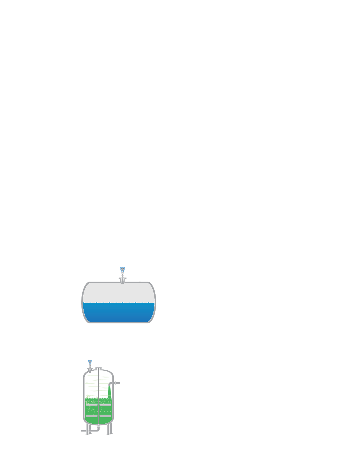
Storage and buffer tanks
The Rosemount 5408 provides accurate and reliable level measurement for both metallic or non-metallic
vessels containing almost any liquid (e.g. oil, gas condensate, water, chemicals).
Reactors
The Rosemount 5408 is ideal for the most challenging applications, including reactors where there can
be agitation, foaming, condensation as well as high temperatures and pressures.
6
Tra nsmitter Over vie w
Page 19

Reference Manual
00809-0100-4408, Rev BA
Blenders and mixers
The Rosemount 5408 can help you withstand the rigors of blenders and mixing tanks. Easy to install and
commission, it is also unaffected by virtually any fluid property change.
Open atmospheric applications
The Rosemount 5408 measures reliably in open applications, from short range sumps or ponds to long
range dams.
Transmitter Overview
November 2017
Still pipe and chamber installations
The Rosemount 5408 is an excellent choice for level measurement in tanks with still pipes. It may also be
used in chambers, but guided wave radar is generally the best fit for these applications. See “Still
pipe/chamber installations” on page 19 for installation guidelines.
Tra nsm itter Overview
7
Page 20

Transmitter Overview
SI
L
2
November 2017
Bulk solids
The Rosemount 5408 is the ideal solution for small to medium sized silos with rapid level changes. The
narrow beam avoids internal obstructions while still keeping good level measurement.
Safety applications
The Rosemount 5408:SIS is the ideal choice for safety functions such as overfill prevention, level
deviation monitoring or dry-run prevention.
Reference Manual
00809-0100-4408, Rev BA
8
Tra nsmitter Over vie w
Page 21
Reference Manual
00809-0100-4408, Rev BA
2.5 Components of the transmitter
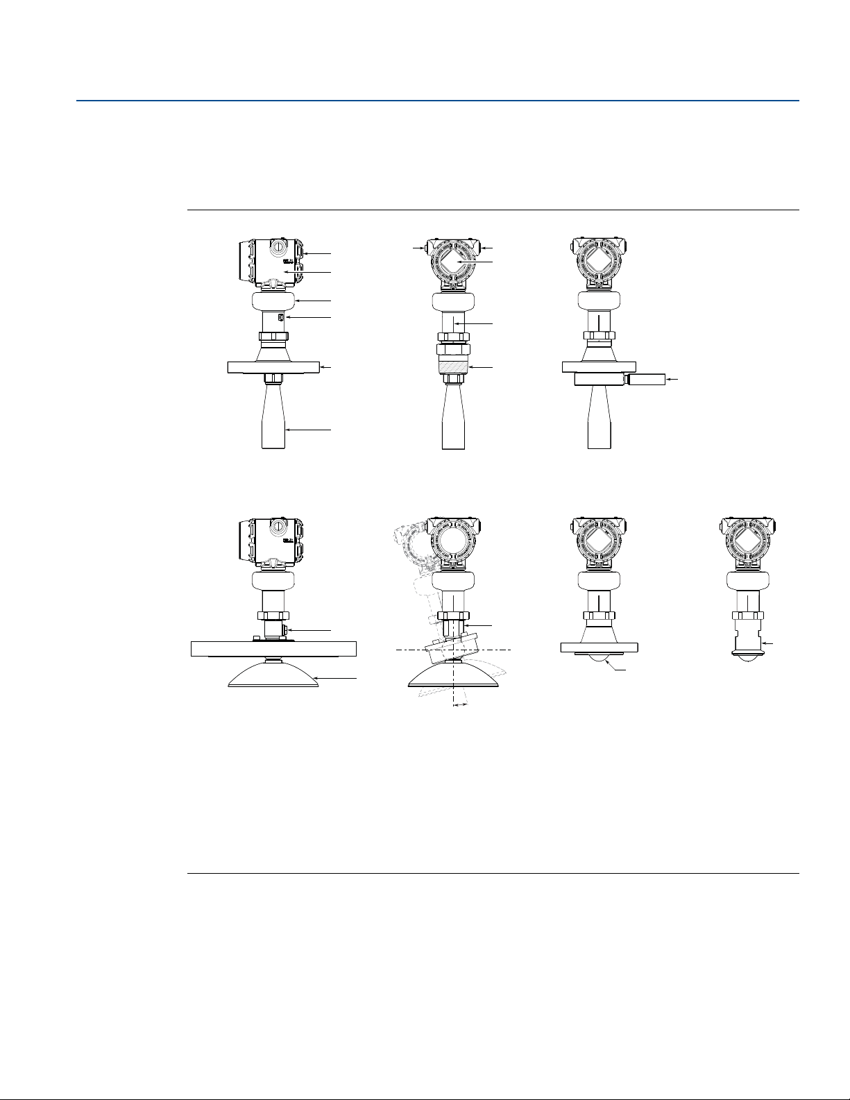
Figure 2-3 shows the different components of the transmitter. There are different antenna types and
sizes available for various applications.
Figure 2-3. Components
Transmitter Overview
November 2017
A
B
C
D
E
F
L
G
G
H
I
J
K
N
P
Tra nsm itter Overview
M
Terminal compartment
A.
Transmitter housing (aluminum or stainless steel)
B.
Sensor module with signal processing electronics
C.
External ground screw
D.
Flanged process connection
E.
Cone antenna
F.
Two cable/conduit entries
G.
(½-14 NPT, M20 x 1.5, or G½)
Optional adapters: eurofast
®
and minifast
O
±15°
LCD display (optional)
H.
Alignment marker (one per side)
I.
Threaded process connection (NPT or BSPP (G))
J.
Air purge ring (option code PC1 for cone antenna)
K.
Integrated air purge connection
L.
Parabolic antenna
M.
Parabolic antenna with swivel mount
N.
Process seal antenna
®
O.
Tri Clamp process connection
P.
9
Page 22

Transmitter Overview
AB C
D
F
G
H
I
E
November 2017
2.6 System integration
The transmitter is loop-powered, and uses the same two wires for power supply and output signal. The
output is a 4-20 mA analog signal superimposed with a digital HART signal. The transmitter can be
configured for either HART Revision 6 (default) or 7 (option code HR7). The HART Revision can be
switched in field.
By using the optional Rosemount 333 HART Tri-Loop
three additional 4-20 mA analog signals. With the HART protocol, multidrop configuration is possible. In
this case, communication is restricted to digital, since current is fixed to the 4 mA minimum value.
The transmitter can be combined with the Emerson
communicate HART data with IEC 62591 (WirelessHART
be connected to a Rosemount 751 Field Signal Indicator, or it can be equipped with an LCD display.
Reference Manual
00809-0100-4408, Rev BA
™
, the digital HART signal can be converted into
™
Wireless 775 THUM™ Adapter to wirelessly
®
) technology. In addition, the transmitter can
The transmitter can easily be configured by using a PC with the Rosemount Radar Master Plus software
(running in the Instrument Inspector
™
Application), a Field Communicator, the AMS Device Manager, or
any other Device Descriptor (DD) or Field Device Integration (FDI) compatible host system.
The Rosemount 5408 and 5408:SIS are compliant with NAMUR NE 107 Field Diagnostics for standardized
device diagnostic information.
Figure 2-4. System Architecture
10
Emerson Wireless 775 THUM Adapter
A.
Rosemount 5408
B.
Rosemount 751
C.
Field Communicator
D.
Approved IS barrier (for Intrinsically Safe installations only)
E.
Rosemount 333
F.
Host/DCS system
G.
HART modem
H.
Rosemount Radar Master Plus or AMS Device Manager
I.
Tra nsmitter Over vie w
Page 23

Reference Manual
00809-0100-4408, Rev BA
Section 3 Mechanical Installation
Safety messages . . . . . . . . . . . . . . . . . . . . . . . . . . . . . . . . . . . . . . . . . . . . . . . . . . . . . . . . . . . . . . . . . . . . . page 11
Confirm approval type . . . . . . . . . . . . . . . . . . . . . . . . . . . . . . . . . . . . . . . . . . . . . . . . . . . . . . . . . . . . . . . page 12
Review mounting considerations . . . . . . . . . . . . . . . . . . . . . . . . . . . . . . . . . . . . . . . . . . . . . . . . . . . . . . page 12
Review mounting preparations . . . . . . . . . . . . . . . . . . . . . . . . . . . . . . . . . . . . . . . . . . . . . . . . . . . . . . . . page 21
Mount the cone antenna . . . . . . . . . . . . . . . . . . . . . . . . . . . . . . . . . . . . . . . . . . . . . . . . . . . . . . . . . . . . . . page 24
Mount the process seal antenna . . . . . . . . . . . . . . . . . . . . . . . . . . . . . . . . . . . . . . . . . . . . . . . . . . . . . . . page 39
Mount the parabolic antenna . . . . . . . . . . . . . . . . . . . . . . . . . . . . . . . . . . . . . . . . . . . . . . . . . . . . . . . . . . page 42
Adjust display orientation (optional) . . . . . . . . . . . . . . . . . . . . . . . . . . . . . . . . . . . . . . . . . . . . . . . . . . . page 57
3.1 Safety messages
Procedures and instructions in this section may require special precautions to ensure the safety of the
personnel performing the operation. Information that raises potential safety issues is indicated by a
warning symbol ( ). Refer to the following safety messages before performing an operation preceded
by this symbol.
Mechanical Installation
November 2017
Failure to follow safe installation and service guidelines could result in death or serious injury.
Make sure the transmitter is installed by qualified personnel and in accordance with applicable code
of practice.
Use the equipment only as specified in this manual. Failure to do so may impair the protection
provided by the equipment.
For installations in hazardous locations, the transmitter must be installed according to the
Rosemount 5408 and 5408:SIS Product Certifications
(D7000002-885).
Process leaks could result in death or serious injury.
Make sure that the transmitter is handled carefully. If the process seal is damaged, gas might escape
from the tank.
Explosions could result in death or serious injury.
Verify that the operating environment of the transmitter is consistent with the appropriate
hazardous locations certifications.
document and System Control Drawing
Mechanical Installation
11
Page 24
Mechanical Installation
November 2017
3.2 Confirm approval type
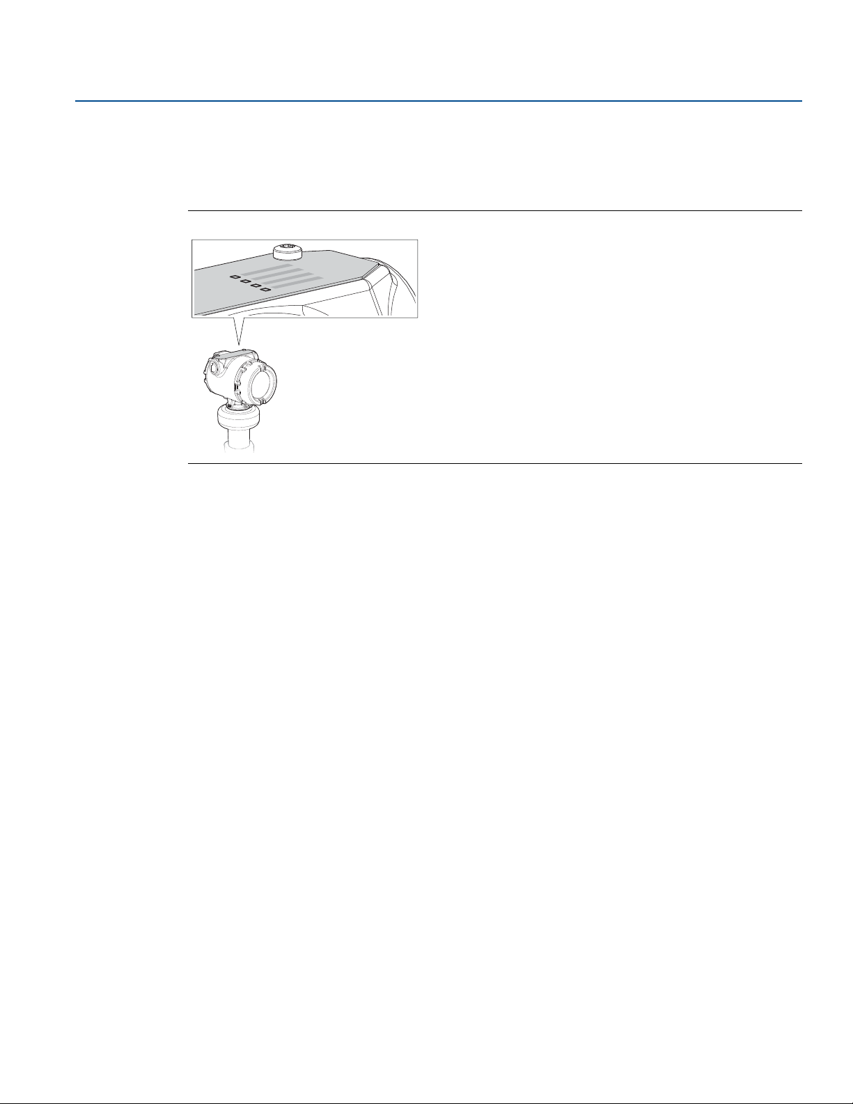
For hazardous locations transmitters labeled with multiple approval types:
Permanently mark the checkbox of the selected approval type(s).
Figure 3-1. Label with Multiple Approval Types
Reference Manual
00809-0100-4408, Rev BA
3.3 Review mounting considerations
Before installing the transmitter, consider recommendations for mounting position, sufficient free
space, nozzle requirements, etc.
3.3.1 Mounting position
When finding an appropriate location on the tank for the transmitter, the conditions of the tank must be
carefully considered.
Consider the following guidelines when mounting the transmitter:
For optimal performance, the transmitter should be installed in locations with a clear and
unobstructed view of the product surface.
The transmitter should be mounted with as few internal structures as possible within the signal beam,
see “Beam width and beam angle” on page 15.
Do not install the transmitter in the center of the tank.
Do not mount close to or above the inlet stream.
Multiple Rosemount
interfering with each other.
™
5408 and 5408:SIS Level Transmitters can be used in the same tank without
12
Mechanical Installation
Page 25

Reference Manual
L
L
B
A
00809-0100-4408, Rev BA
Figure 3-2. Recommended Mounting Position
Mechanical Installation
November 2017
3.3.2 Free space requirements
If the transmitter is mounted close to a wall or other tank obstructions such as heating coils and ladders,
noise might appear in the measurement signal. Therefore the following minimum clearance, according
to Ta b le 3 - 1 , must be maintained.
For easy access to the transmitter, mount it with sufficient service space (see Ta bl e 3 - 2).
Figure 3-3. Free Space Requirements
Mechanical Installation
Table 3-1. Distance to Tank Wall (L)
Application Minimum Recommended
Liquids 8 in. (200 mm)
Solids 8 in. (200 mm)
1
/2 of tank radius
2
/3 of tank radius
13
Page 26
Mechanical Installation
90°
Max. 3° Max. 1.5°
90°
Cone antenna/
process seal antenna
Parabolic antenna
November 2017
Table 3-2. Free Space Requirements
Description Distance
Service space width (A) 20 in. (500 mm)
Service space height (B) 24 in. (600 mm)
3.3.3 Antenna size
Choose as large antenna diameter as possible. A larger antenna diameter concentrates the radar beam
and ensures maximum antenna gain. Increased antenna gain permits greater margin for weak surface
echoes.
In addition, a larger antenna diameter results in a smaller beam angle and thereby, less interference from
any internal structures in the tank.
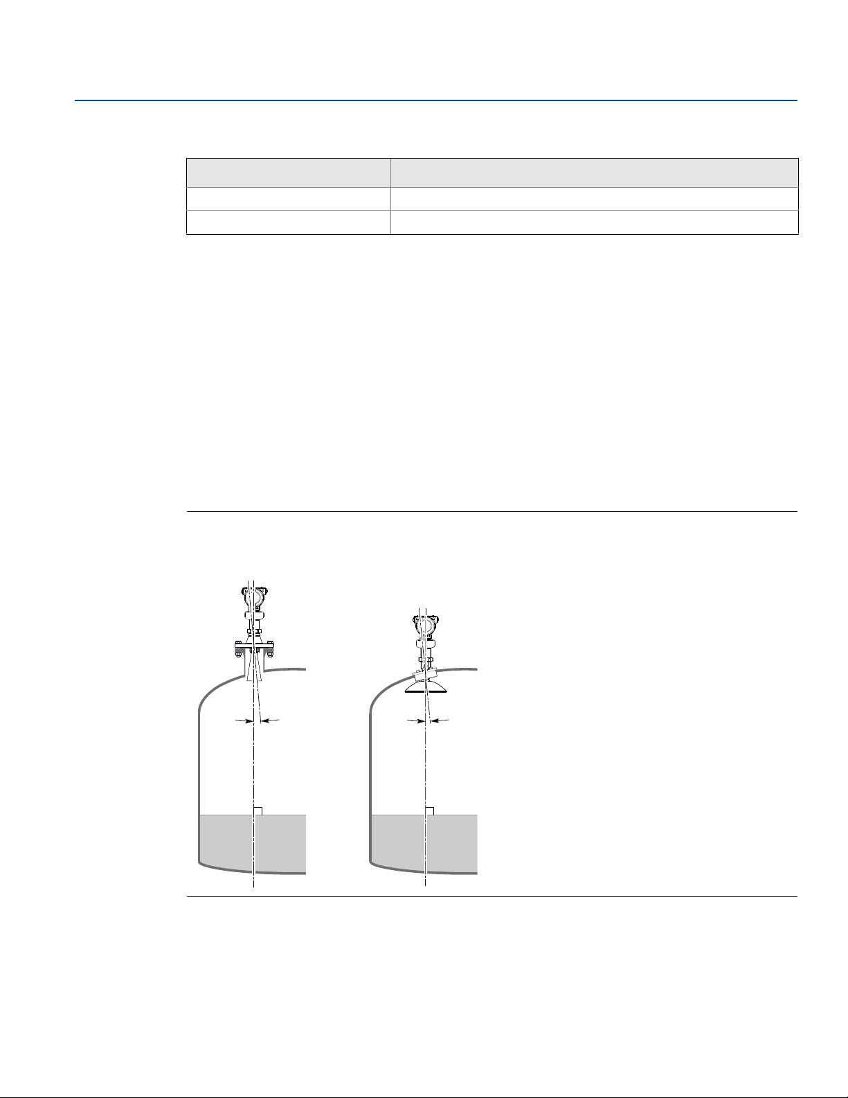
3.3.4 Antenna inclination
Ensure the antenna is aligned perpendicular to the product surface (see Figure 3-4). The parabolic
antenna comes with a swivel connection that adjusts for angled tank roofs.
Reference Manual
00809-0100-4408, Rev BA
Note that if the surface echo is weak in solids applications, then a small inclination of the parabolic
antenna toward the surface slope may improve the performance.
Figure 3-4. Inclination
3.3.5 Non-metallic tanks
The walls in non-metallic tanks can be invisible to the radar signal, so nearby objects outside the tank
may cause disturbing radar echoes. Wherever possible, the transmitter should be positioned so that
14
objects close to the tank are kept outside the signal beam.
Mechanical Installation
Page 27
Reference Manual
D
W
00809-0100-4408, Rev BA
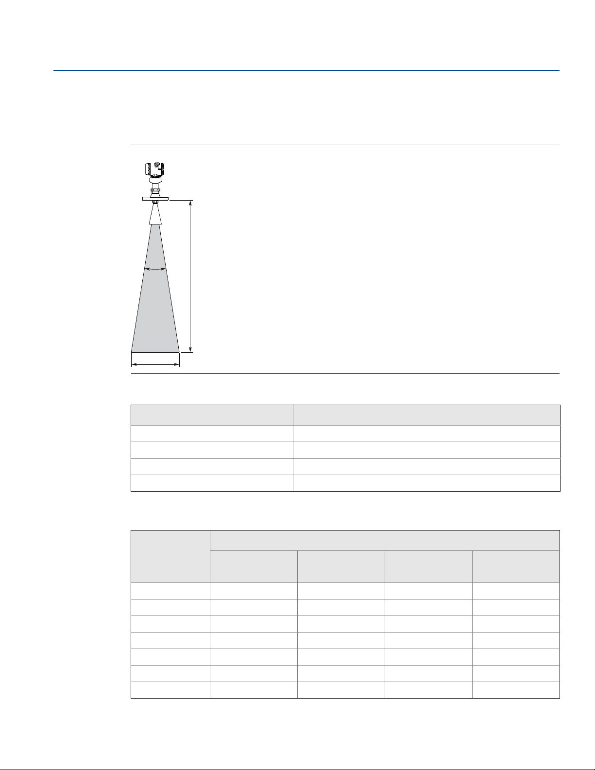
3.3.6 Beam width and beam angle
The transmitter should be mounted with as few internal structures as possible within the signal beam.
Refer to Ta b le 3 - 3 for beam angle and Tab l e 3 -4 for beam width at different distances.
Figure 3-5. Beam Angle and Beam Width
Mechanical Installation
November 2017
Table 3-3. Beam Angle
Antenna size Beam angle (α)
2-in. (DN50) cone/process seal 18°
3-in. (DN80) cone/process seal 14°
4-in. (DN100) cone/process seal 10°
8-in. (DN200) parabolic 4.5°
Table 3-4. Beam Width, ft. (m)
Distance (D) Beam width (W)
2-in. cone/
process seal
16 (5) 5.2 (1.6) 4.0 (1.2) 2.9 (0.9) 1.3 (0.4)
33 (10) 10.4 (3.2) 8.1 (2.5) 5.7 (1.8) 2.6 (0.8)
49 (15) 15.6 (4.8) 12.1 (3.7) 8.6 (2.6) 3.9 (1.2)
66 (20) 20.8 (6.3) 16.1 (4.9) 11.5 (3.5) 5.2 (1.6)
82 (25) 26.0 (7.9) 20.1 (6.1) 14.3 (4.4) 6.4 (2.0)
98 (30) 31.2 (9.5) 24.2 (7.4) 17.2 (5.3) 7.7 (2.4)
131 (40) 41.6 (12.7) 32.2 (9.8) 23.0 (7.0) 10.3 (3.1)
3-in. cone/
process seal
4-in. cone/
process seal
Parabolic
Mechanical Installation
15
Page 28

Mechanical Installation
D
H
> 0.4 in. (10 mm)
November 2017
3.3.7 Nozzle requirements
In order to allow the microwaves to propagate undisturbed, the nozzle dimensions should be kept within
the specified limits as given in Ta bl e 3 - 5, Tab l e 3 -6 , and Ta b le 3- 7 .
Cone antenna
For best performance, the cone antenna should extend at least 0.4 in. (10 mm) below the nozzle. If
required, use the extended cone antenna versions (option code S1 or S2).
However, the antenna can be recessed in smooth nozzles up to 4 ft. (1.2 m). Note that if the inside of the
nozzle has irregularities (e.g. due to bad welding, rust, or deposit), then use the extend cone antenna.
Figure 3-6. Mounting of the Cone Antenna
Reference Manual
00809-0100-4408, Rev BA
16
Table 3-5. Nozzle Requirements for Cone Antenna, in Inches (Millimeters)
Antenna size Minimum nozzle
diameter (D)
(1)
Recommended maximum nozzle height (H)
(2)(3)
Antenna Antenna with air purge ring
(code PC1)
2-in. (DN50) 1.94 (49.3) 5.71 (145) 4.69 (119)
3-in. (DN80) 2.80 (71.0) 5.63 (143) 4.61 (117)
4-in. (DN100) 3.78 (96.0) 6.54 (166) 5.51 (140)
1. The antennas are sized to fit within schedule 80 or lower schedules.
2. The values are valid for cone antennas without antenna extension.
3. For liquid applications, the cone antenna can be recessed in smooth nozzles up to 4 ft. (1.2 m), but note that the accuracy may be reduced
in the region close to the nozzle.
Mechanical Installation
Page 29

Reference Manual
D
H
00809-0100-4408, Rev BA
Process seal antenna
The antenna can be used on nozzles up to 4 ft. (1.2 m). Disturbing objects inside the nozzle may impact
the measurement, and should therefore be avoided.
Figure 3-7. Mounting of the Process Seal Antenna
Mechanical Installation
November 2017
Table 3-6. Nozzle Requirements for Process Seal Antenna
Antenna size Minimum nozzle diameter (D)
2-in. (DN50) 1.77 in. (45 mm) 4 ft. (1.2 m)
3-in. (DN80) 2.76 in. (70 mm) 4 ft. (1.2 m)
4-in. (DN100) 2.76 in. (70 mm) 4 ft. (1.2 m)
1. The antennas are sized to fit within schedule 120 or lower schedules.
(1)
Recommended maximum nozzle height (H)
Mechanical Installation
17
Page 30
Mechanical Installation
α
H
Ø
8
i
n
.
(
2
0
0
m
m
)
D
Nozzle mounting Flange mounting in manhole cover
α
H
November 2017
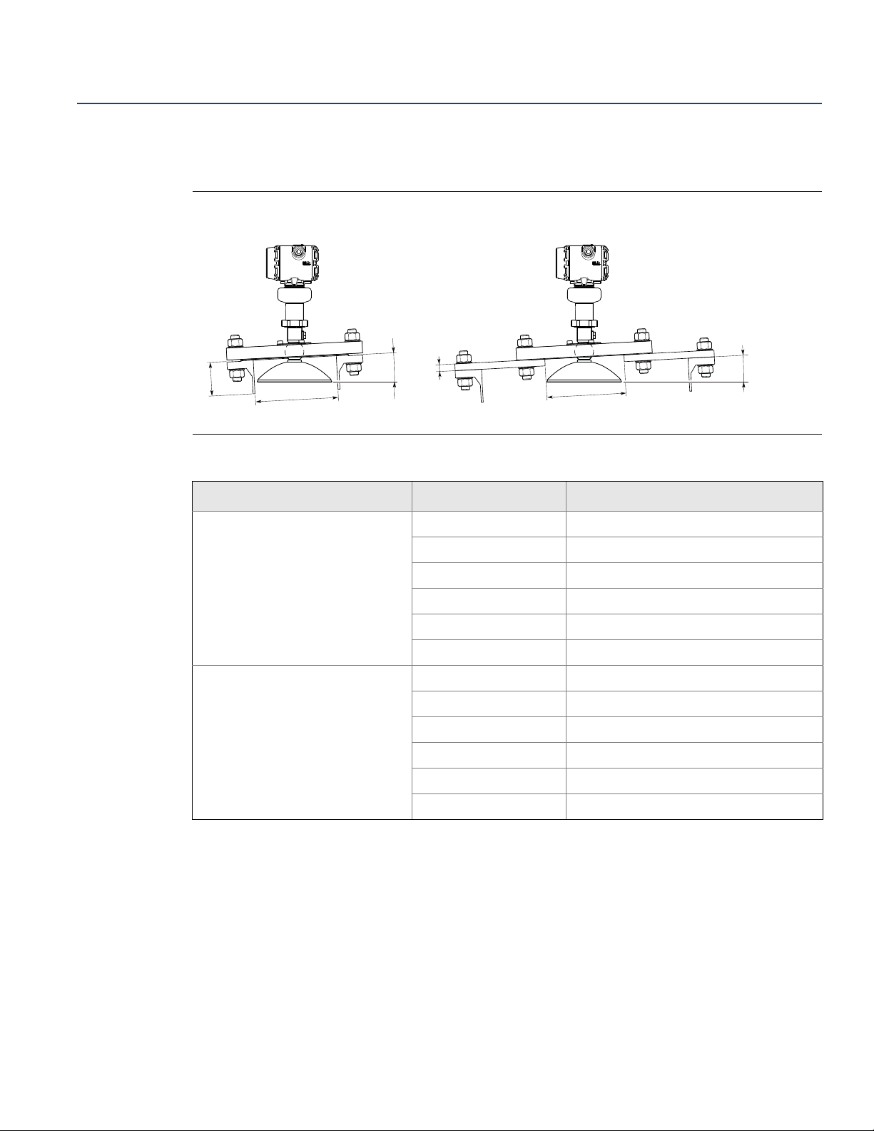
Parabolic antenna
See Ta bl e 3 - 7 for nozzle height recommendations at different inclination angle.
Figure 3-8. Mounting of the Parabolic Antenna
Table 3-7. Nozzle Requirements for Parabolic Antenna, in Inches (Millimeters)
Reference Manual
00809-0100-4408, Rev BA
Nozzle size (D) Inclination angle (α) Maximum nozzle height (H)
Pipe schedule std, Ø 8 in. (200 mm)
Pipe schedule std, Ø10 in. (250 mm)
1. Note that the inside of the nozzle must be smooth (i.e. avoid bad welding, rust, or deposit).
0° 5.9 (150)
3° 5.5 (140)
6° 1.6 (40)
9° 1.2 (30)
12° 1.0 (25)
15° 0.6 (15)
0° 8.0 (200)
3° 8.0 (200)
6° 8.0 (200)
9° 8.0 (200)
12° 5.9 (150)
15° 4.3 (110)
(1)
18
Mechanical Installation
Page 31
Reference Manual
Max. 1 in. (25 mm)
Max. 0.2 in.
(5 mm)
Min. 6 in. (150 mm)
Max. 1°
Level = 100%
Level = 0%
00809-0100-4408, Rev BA
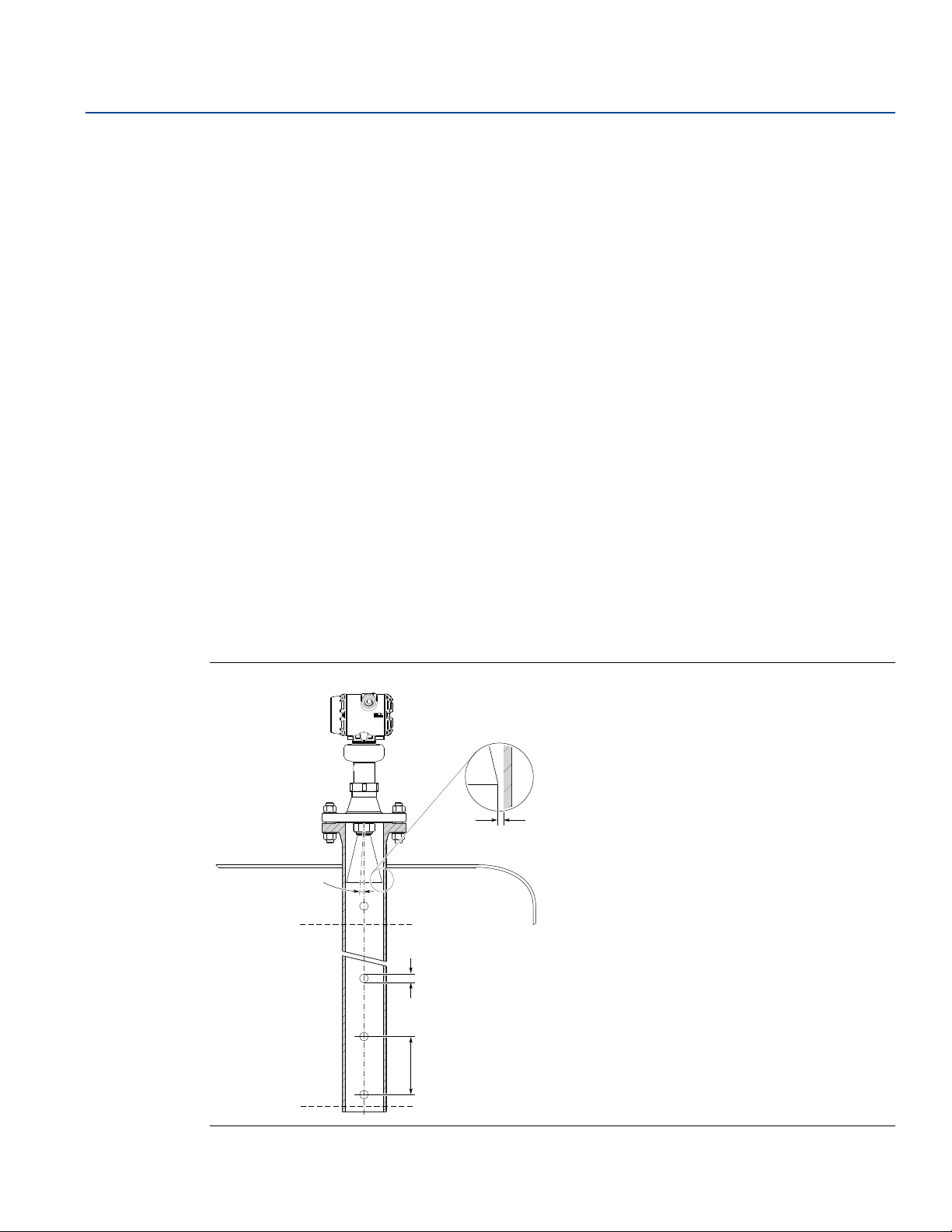
3.3.8 Still pipe/chamber installations
Installation in still pipe/chamber is recommended for tanks where there are excessive foaming or
turbulence. Still pipe/chamber may also be used to avoid disturbing objects in the tank.
All cone/process seal antenna sizes can be used for still pipe/chamber installations.
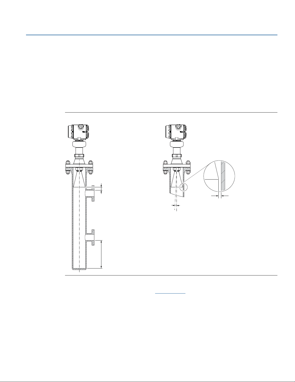
Still pipe
Consider the following still pipe requirements:
Pipe
Pipes should be an all-metal material.
Pipe should have a constant inside diameter.
The inner surface must be smooth and clear of any rough edges.
(Smooth pipe joints are acceptable, but may reduce accuracy.)
The end of the pipe must extend beyond the zero level.
Holes
Maximum hole diameter is 1 in. (25 mm).
Minimum distance between holes is 6 in. (150 mm).
Holes should be drilled on one side only and deburred.
Drill one hole above maximum product surface.
Mechanical Installation
November 2017
Antenna
The gap between the cone antenna and the still pipe should be maximum 0.2 in. (5 mm). If required,
order a larger antenna and cut on location. See Figure A-10 on page 163 for antenna dimensions.
Figure 3-9. Still Pipe Requirements
Mechanical Installation
19
Page 32
Mechanical Installation
Max. 0.2 in.
(5 mm)
Min. 6 in. (150 mm)
Max. 1°
Min. 0.4 in. (10 mm)
November 2017
Chamber
Consider the following chamber requirements:
Pipes should be an all-metal material.
Pipe should have a constant inside diameter.
Inlet pipes should not protrude into the inside of the stand pipe.
The inner surface must be smooth and clear of any rough edges.
(Smooth pipe joints are acceptable, but may reduce accuracy.)
The gap between the cone antenna and the stand pipe should be maximum 0.2 in. (5 mm). If required,
order a larger antenna and cut on location. See Figure A-10 on page 163 for antenna dimensions.
Figure 3-10. Chamber Requirements
Reference Manual
00809-0100-4408, Rev BA
For more information and installation requirements, refer to the Guidelines for Choosing and Installing
Radar in Stilling Wells and Bypass Chambers Techni cal N ote
3.3.9 Ball valve installation
The transmitter can be isolated from the process by using a valve:
Use a full-port ball valve.
Ensure there is no edge between the ball valve and the nozzle or still pipe, the inside should be
smooth.
Valves can be combined with still pipes.
20
.
Mechanical Installation
Page 33
Reference Manual
00809-0100-4408, Rev BA
3.4 Review mounting preparations
3.4.1 Assemble the segmented cone antenna
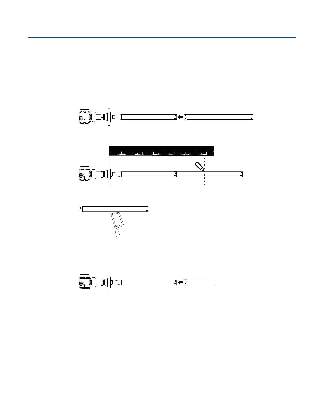
This section applies to the segmented cone antenna (option code S2). Use only one segment; the total
antenna length should not exceed 47.2 in. (1200 mm).
To determine the antenna length, follow the guidelines in section “Nozzle requirements” on page 16.
1. Insert the segment into the cone antenna until it bottoms.
2. Mark where to cut the segment.
0
12
3
4
5
6
8
7
Mechanical Installation
November 2017
9
3. Remove and cut the segment at the marking.
4. Remove any burrs.
5. Insert the segment into the cone antenna until it bottoms.
Mechanical Installation
21
Page 34

Mechanical Installation
L
12
3
4
5
6
7
8
0
9
November 2017
6. Secure the segment to the antenna.
Reference Manual
00809-0100-4408, Rev BA
1
2
3 4
7. Measure the Antenna Extension Length (L).
8. Update the transmitter configuration to the new Antenna Extension Length (L).
Rosemount Radar Master Plus: AMS Device Manager and Field Communicator:
Under Configure, select Level Setup > Antenna. Select Configure > Manual Setup > Level Setup >
Antenna.
22
Mechanical Installation
Page 35
Reference Manual
12
3
4
5
6
0
00809-0100-4408, Rev BA
3.4.2 Shorten the extended cone antenna
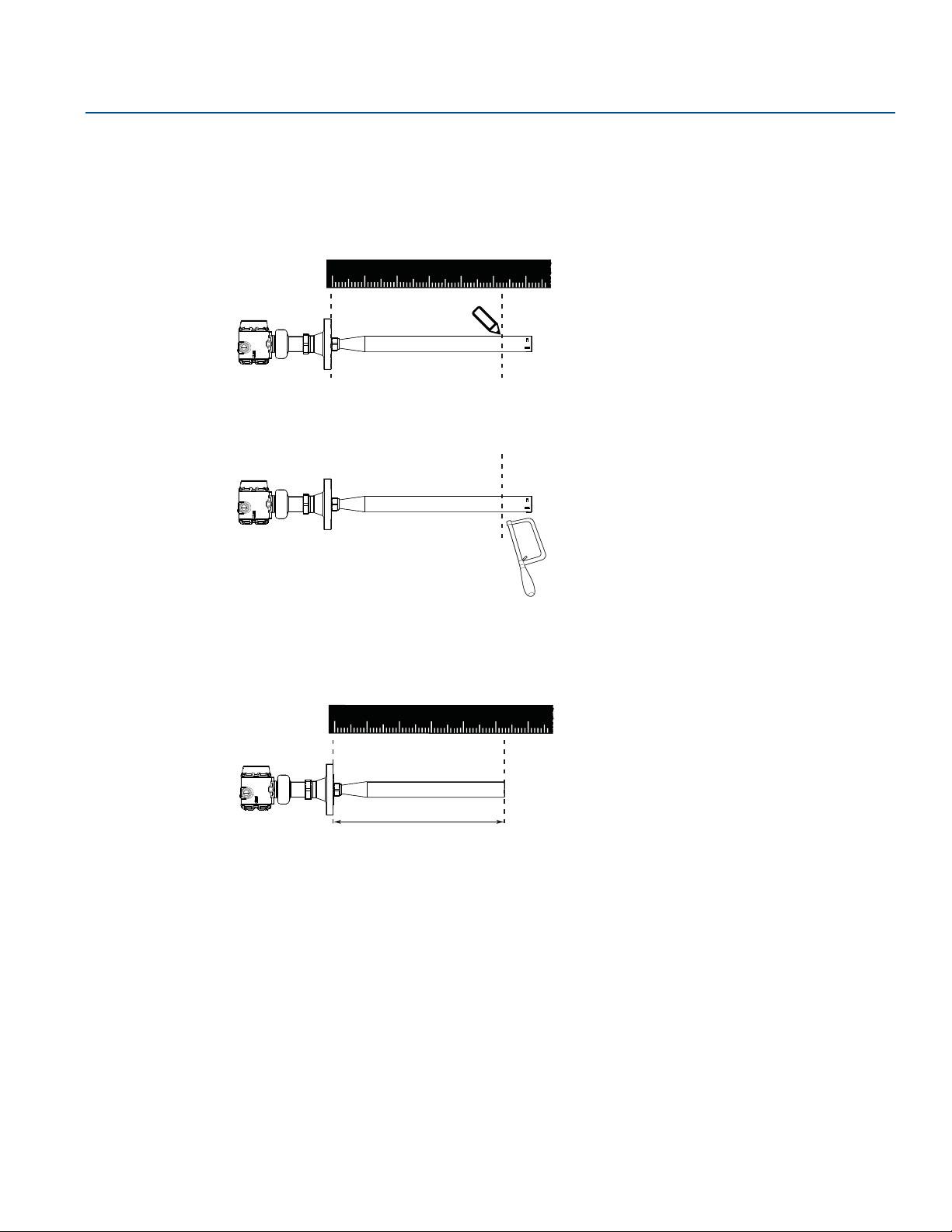
This section only applies to the extended cone antenna (option code S1).
To determine the antenna length, follow the guidelines in section “Nozzle requirements” on page 16.
1. Mark where to cut the antenna.
2. Cut the antenna at the marking.
Mechanical Installation
November 2017
3. Remove any burrs.
4. Measure the Antenna Extension Length (L).
3
4
5
0
12
6
L
5. Update the transmitter configuration to the new Antenna Extension Length (L).
Rosemount Radar Master Plus: AMS Device Manager and Field Communicator:
Under Configure, select Level Setup > Antenna. Select Configure > Manual Setup > Level Setup >
Antenna.
Mechanical Installation
23
Page 36
Mechanical Installation
d
D
d
D
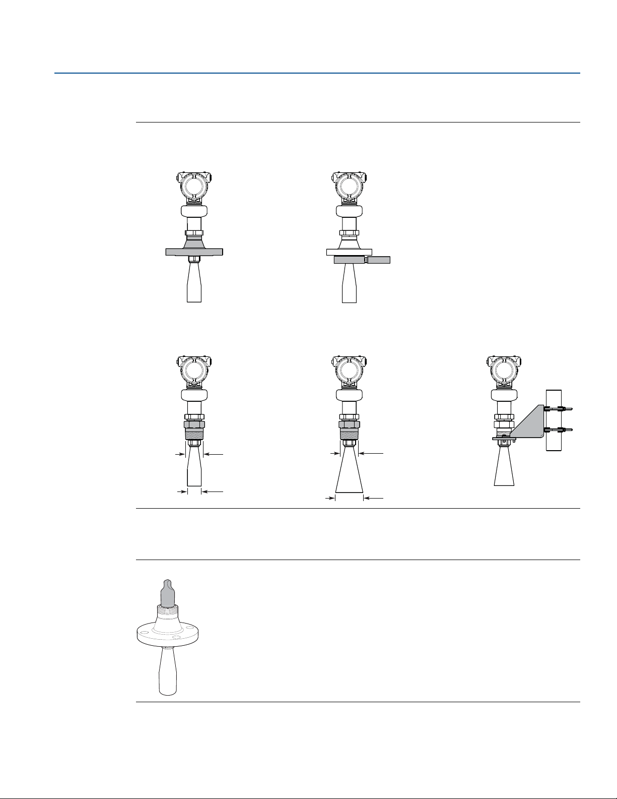
Flanged version
(see page 25)
Flanged version with air purge ring
(see page 26)
Threaded version, D
< d
(see page 28)
Threaded version, D > d
(see page 31)
Bracket mounting
(see page 34)
November 2017
3.5 Mount the cone antenna
Figure 3-11. Overview
Reference Manual
00809-0100-4408, Rev BA
For spare antennas, keep the protective cap in place until installing the transmitter head. The cap
protects the process seal from dust and water.
Figure 3-12. Protective Cap
24
Mechanical Installation
Page 37
Reference Manual
Gasket
00809-0100-4408, Rev BA
3.5.1 Flanged version
1. Lower transmitter with antenna and flange into the nozzle.
Mechanical Installation
November 2017
2. Tighten bolts and nuts with sufficient torque for the flange and gasket choice.
3. Align the transmitter head (see page 37).
Mechanical Installation
25
Page 38
Mechanical Installation
Antenna with air purge holes
November 2017
Reference Manual
00809-0100-4408, Rev BA
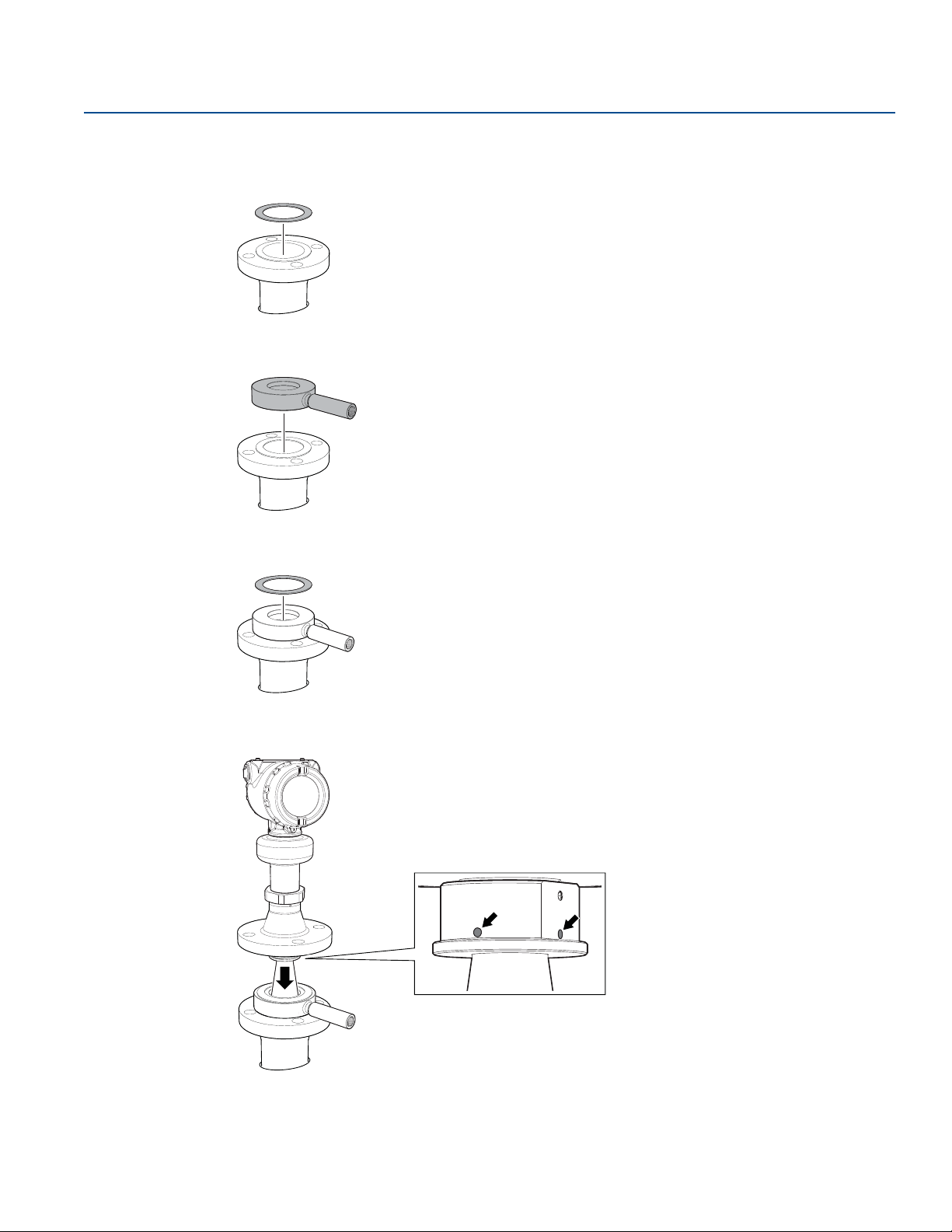
3.5.2 Flanged version with air purge ring (option code PC1)
1. Place a suitable gasket on the tank flange.
2. Place the purge ring over the gasket.
3. Place a suitable gasket over the purge ring.
4. Lower transmitter with antenna and flange into the nozzle.
26
Mechanical Installation
Page 39
Reference Manual
1.0 in. (25.5 mm)
G3/8-in.
0.4 in. (10 mm)
or
00809-0100-4408, Rev BA
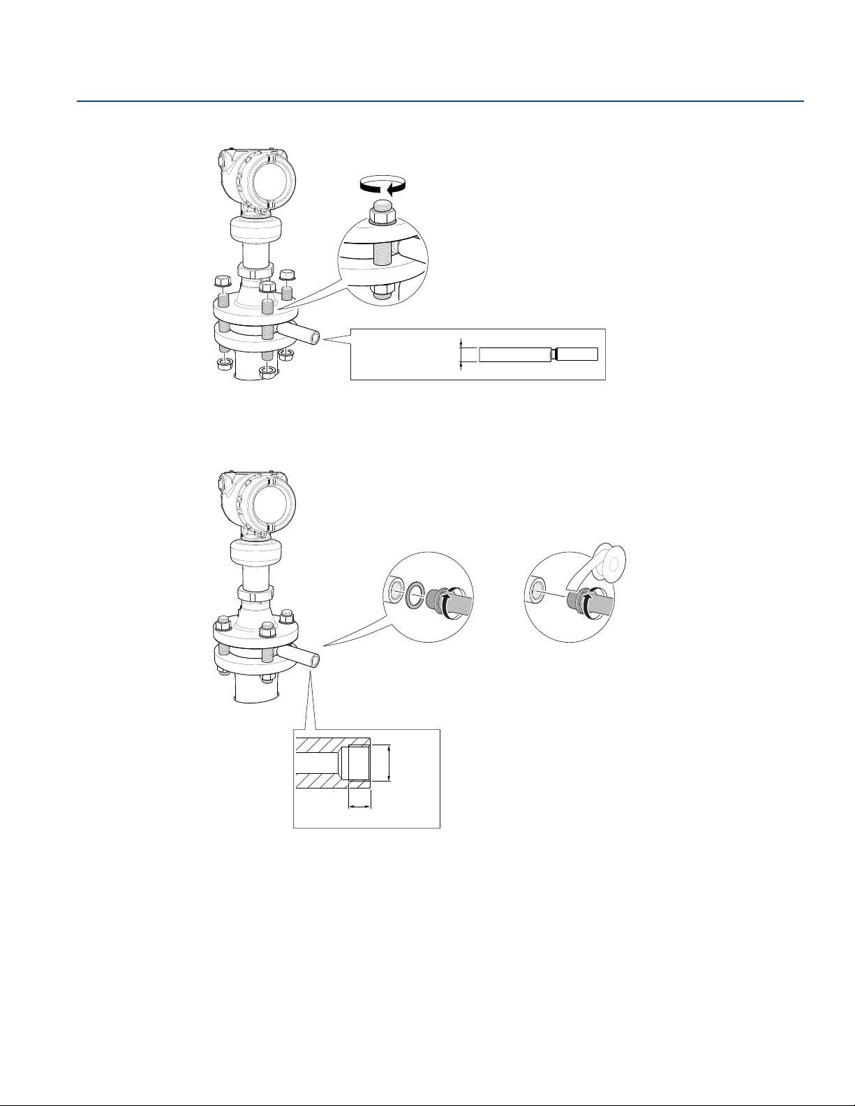
5. Tighten bolts and nuts with sufficient torque for the flange and gasket choice.
6. Connect the air purging system. Refer to page 142 for air supply specification.
Use thread sealant or suitable gasket according to your site procedures.
Mechanical Installation
November 2017
Mechanical Installation
7. Align the transmitter head (see page 37).
27
Page 40
Mechanical Installation
November 2017
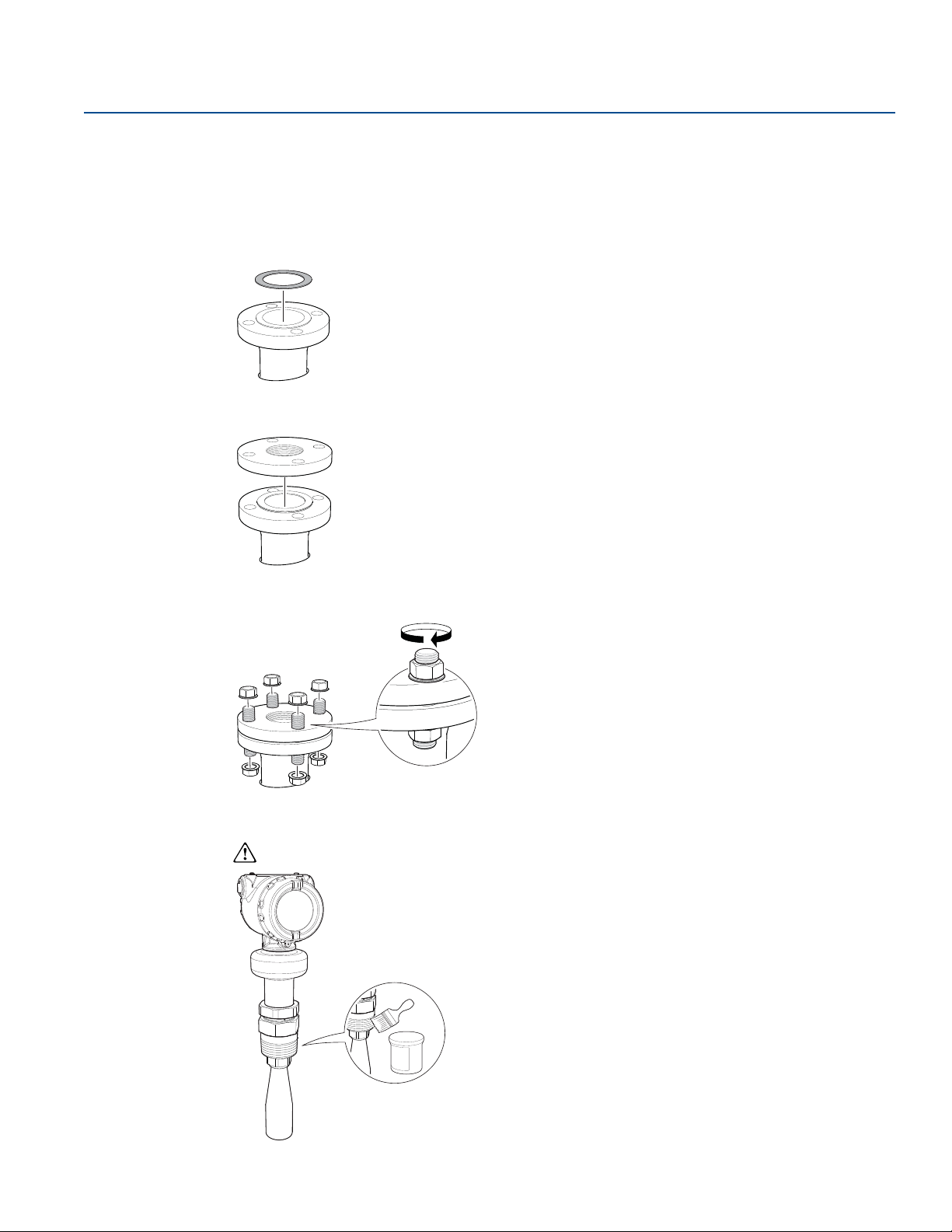
3.5.3 Threaded version
Antenna diameter (D) < Thread diameter (d)
Flanged tank connection
1. Place a suitable gasket on the tank flange.
2. Place the customer supplied flange over the gasket.
Reference Manual
00809-0100-4408, Rev BA
3. Tighten the bolts and nuts with sufficient torque for the flange and gasket choice.
4. Apply anti-seize paste or PTFE tape on threads according to your site procedures.
Gasket may be used as a sealant for adapters with 1½- or 2-in. BSPP (G) threads.
28
Mechanical Installation
Page 41
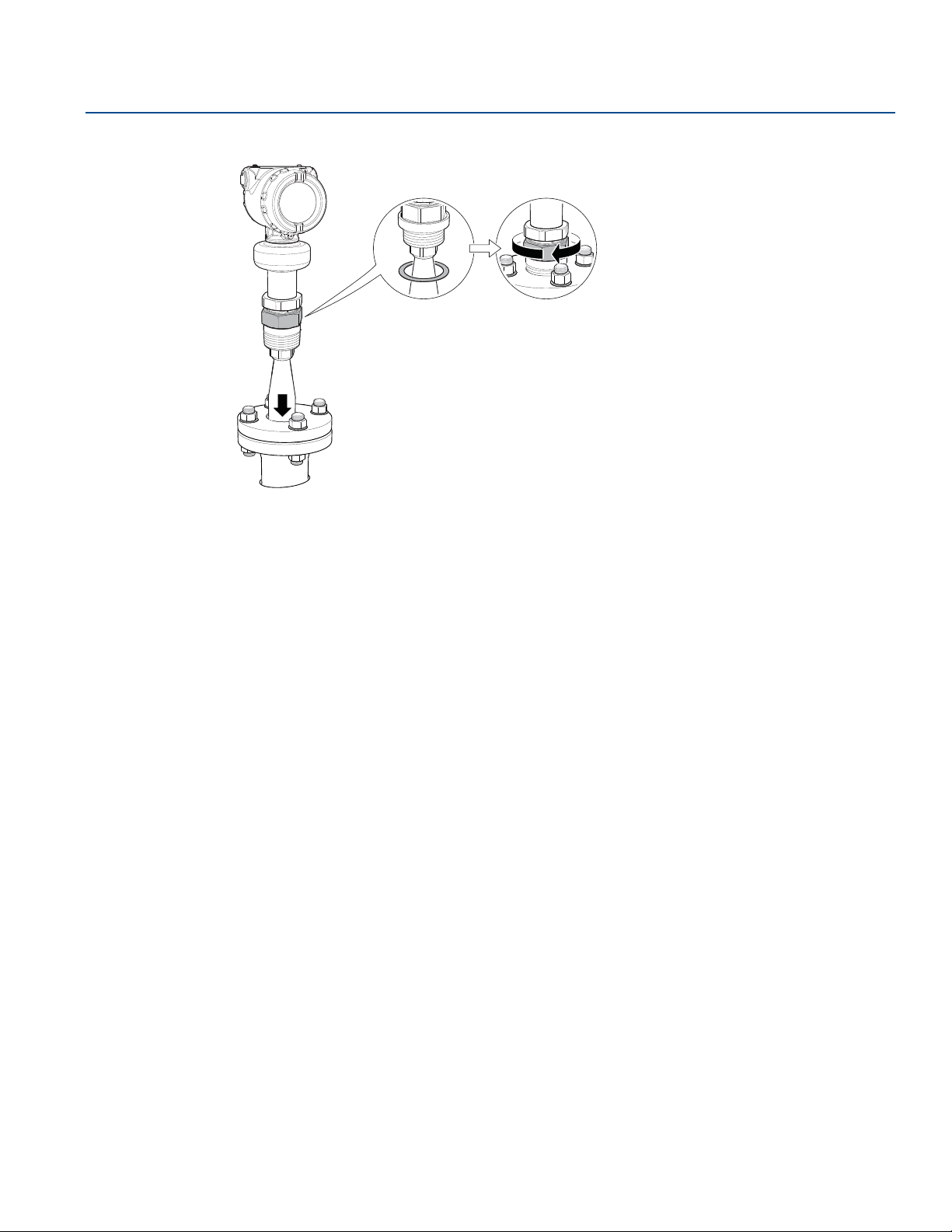
Reference Manual
Gasket
(for 1½-in. and 2-in. BSPP (G)
threads only)
00809-0100-4408, Rev BA
5. Lower transmitter with antenna and flange into the nozzle.
Mechanical Installation
November 2017
6. Align the transmitter head (see page 37).
Mechanical Installation
29
Page 42
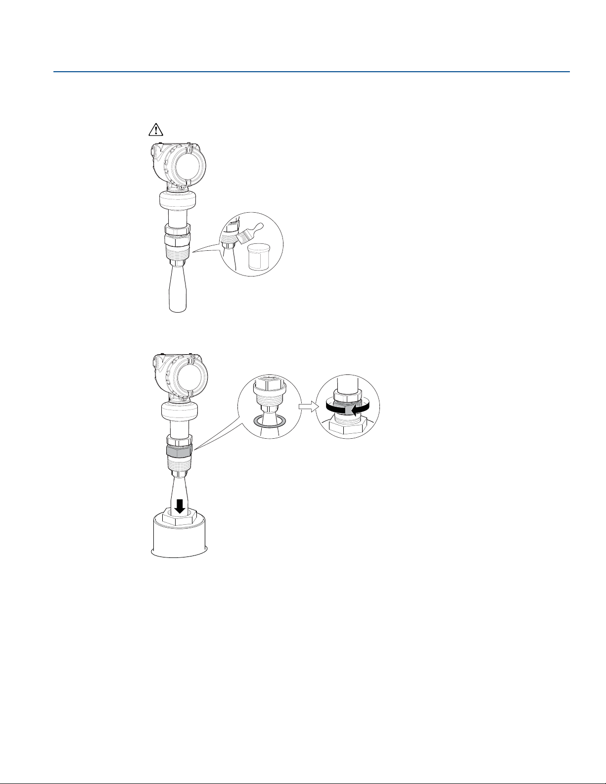
Mechanical Installation
Gasket
(for 1½-in. and 2-in. BSPP (G)
threads only)
November 2017
Threaded tank connection
1. Apply anti-seize paste or PTFE tape on threads according to your site procedures.
Gasket may be used as a sealant for adapters with 1½- or 2-in. BSPP (G) threads.
Reference Manual
00809-0100-4408, Rev BA
2. Mount the transmitter on the tank.
3. Align the transmitter head (see page 37).
30
Mechanical Installation
Page 43
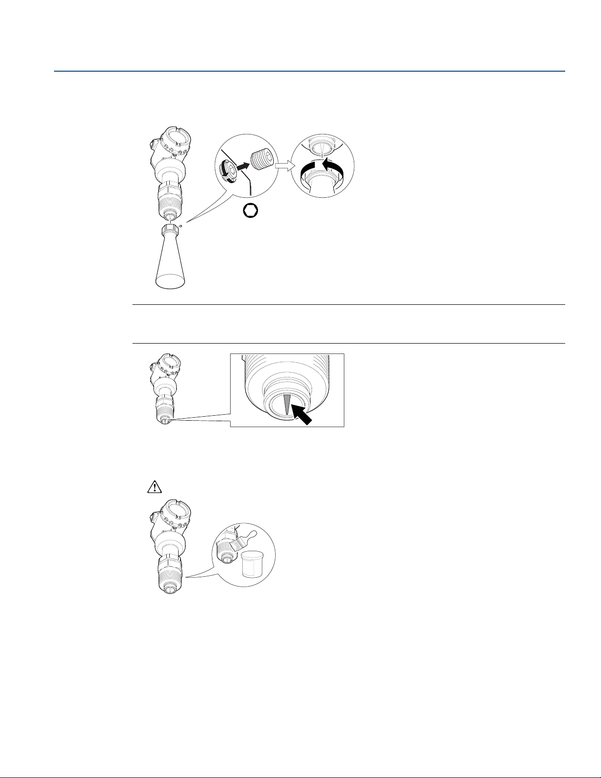
Reference Manual
Microwave launcher
00809-0100-4408, Rev BA
Antenna diameter (D) > Thread diameter (d)
1. Unscrew and remove the antenna.
Note
Be careful not to scratch the microwave launcher. The microwave launcher is sensitive to mechanical
impacts.
Mechanical Installation
November 2017
H2 mm
Mechanical Installation
2. Apply anti-seize paste or PTFE tape on threads according to your site procedures.
Gasket may be used as a sealant for adapters with 1½- or 2-in. BSPP (G) threads.
31
Page 44
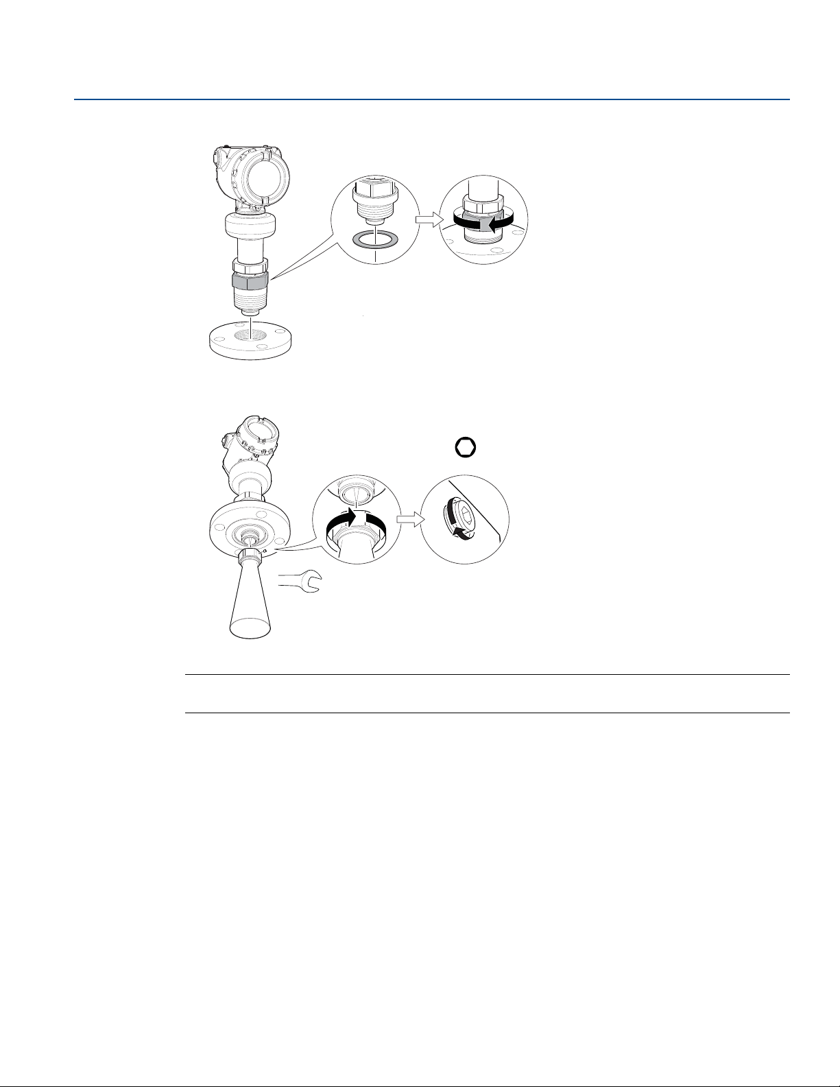
Mechanical Installation
Gasket
(for 1½-in. and 2-in. BSPP (G)
threads only)
Tor que 5 in-l b (0 .5 N- m)
H2 mm
Torque 250 in-lb (28 N-m)
38 mm
November 2017
3. Mount the adapter on the customer supplied flange.
4. Mount the antenna.
Reference Manual
00809-0100-4408, Rev BA
32
Note
Visually inspect the microwave launcher for damage and dirt. See page 31.
Mechanical Installation
Page 45
Reference Manual
Gasket
00809-0100-4408, Rev BA
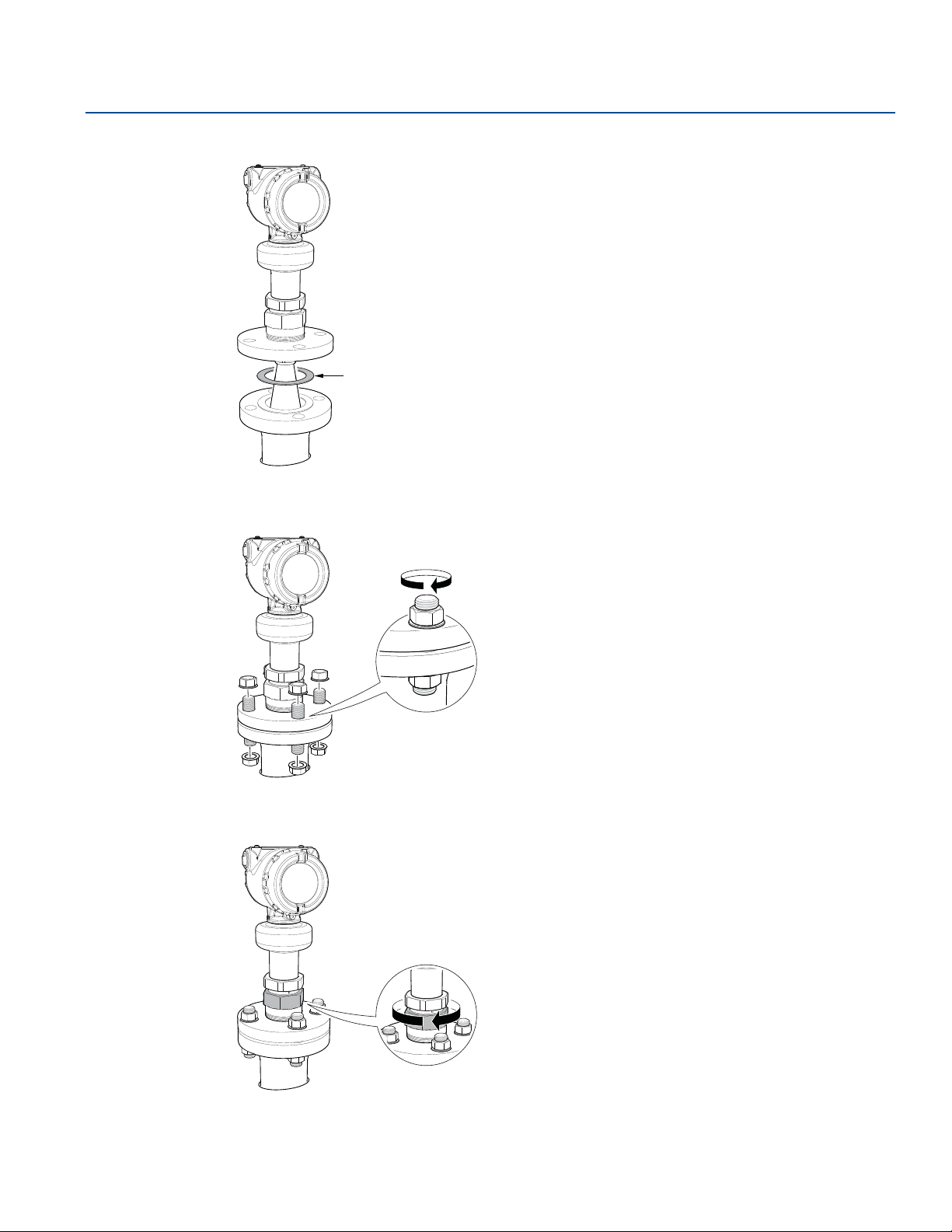
5. Lower transmitter with antenna and flange into the nozzle.
Mechanical Installation
November 2017
6. Tighten the bolts and nuts with sufficient torque for the flange and gasket choice.
7. Screw the adapter until it is properly tightened.
Mechanical Installation
8. Align the transmitter head (see page 37).
33
Page 46
Mechanical Installation
4X
Vertical pipe
Horizontal pipe
4X
Use screws suitable
for the purpose
November 2017
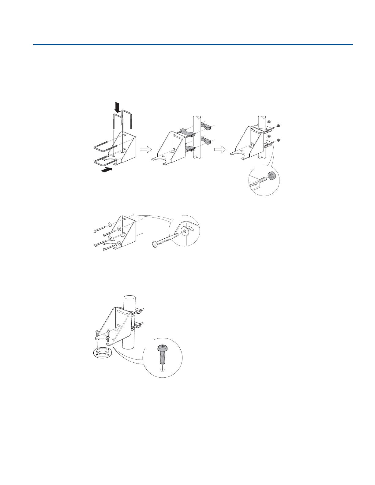
3.5.4 Bracket mounting
1. Mount the bracket to the pipe/wall.
On pipe:
Reference Manual
00809-0100-4408, Rev BA
On wall:
2. Mount the holder to the bracket.
3X
34
Mechanical Installation
Page 47
Reference Manual
Microwave launcher
00809-0100-4408, Rev BA
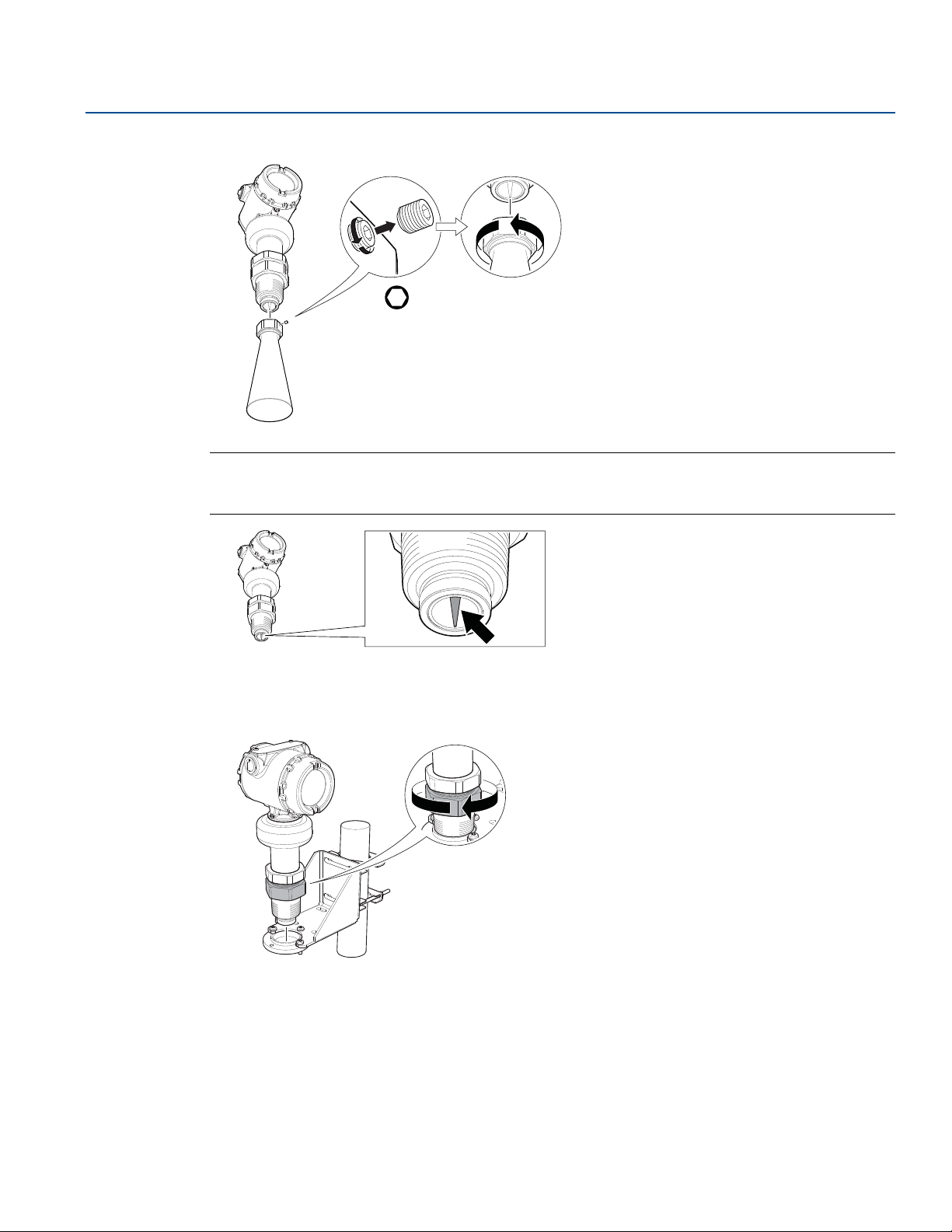
3. Unscrew and remove the antenna.
Note
Be careful not to scratch the microwave launcher. The microwave launcher is sensitive to mechanical
impacts.
Mechanical Installation
November 2017
H2 mm
Mechanical Installation
4. Screw the transmitter into the holder.
35
Page 48
Mechanical Installation
Tor que 5 in -lb (0. 5 N- m)
H2 mm
Torque 250 in-lb (28 N-m)
38 mm
November 2017
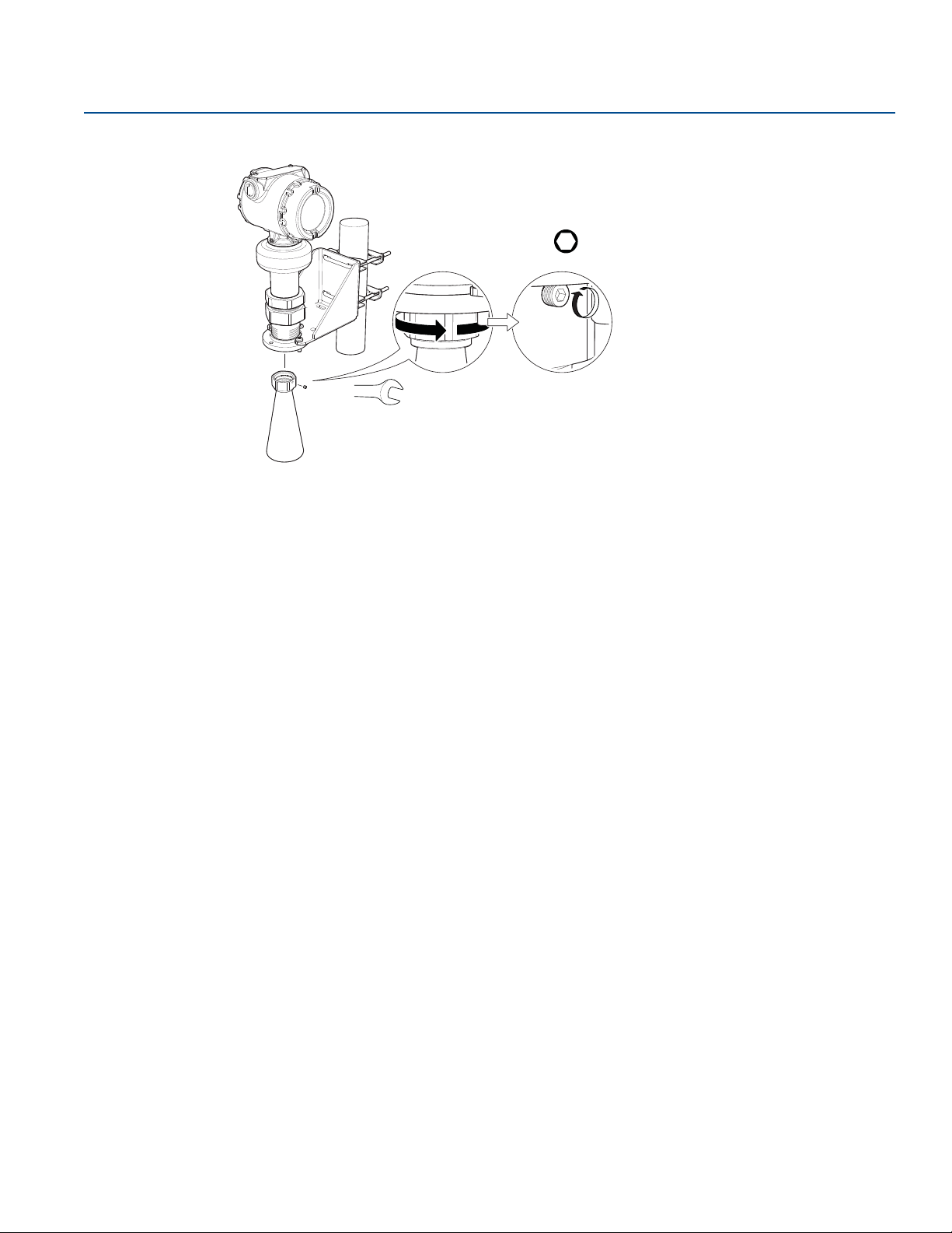
5. Mount the antenna.
6. Align the transmitter head (see page 37).
Reference Manual
00809-0100-4408, Rev BA
36
Mechanical Installation
Page 49
Reference Manual
00809-0100-4408, Rev BA
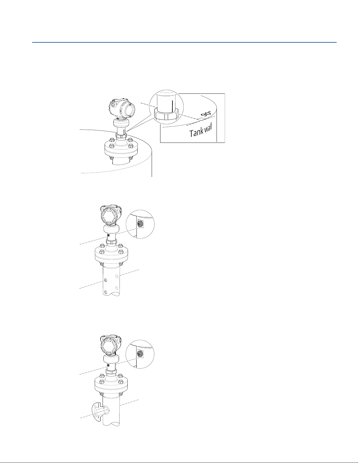
3.5.5 Align transmitter head
Open tank
Align the marking on the sensor module toward the tank wall.
Still pipe
Mechanical Installation
November 2017
Align the external ground screw toward the holes of the still pipe.
Chamber
Align the external ground screw toward the process connections.
Mechanical Installation
37
Page 50
Mechanical Installation
60 mm
Torque 355 in-lb (40 N-m)
60 mm
November 2017
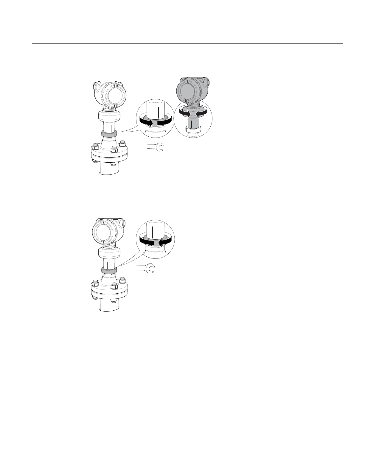
Procedure
1. Loosen the nut slightly and turn the transmitter.
2. Verify the transmitter head is properly aligned (see page 37 for direction).
Reference Manual
00809-0100-4408, Rev BA
3. Tighten the nut.
38
Mechanical Installation
Page 51
Reference Manual
Flanged version
(see page 39)
Tri Clamp ve rsion
(see page 41)
PTFE sealing
00809-0100-4408, Rev BA
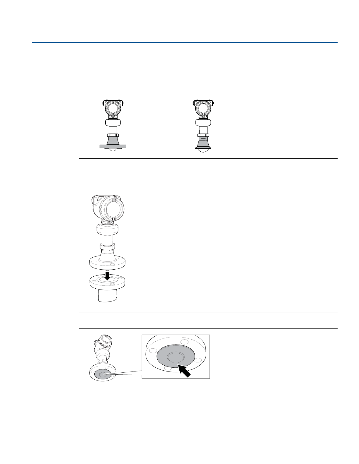
3.6 Mount the process seal antenna
Figure 3-13. Overview
3.6.1 Flanged version
1. Lower the transmitter into the nozzle.
Mechanical Installation
November 2017
Mechanical Installation
Note
Be careful not to scratch or otherwise damage the PTFE sealing.
39
Page 52
Mechanical Installation
November 2017
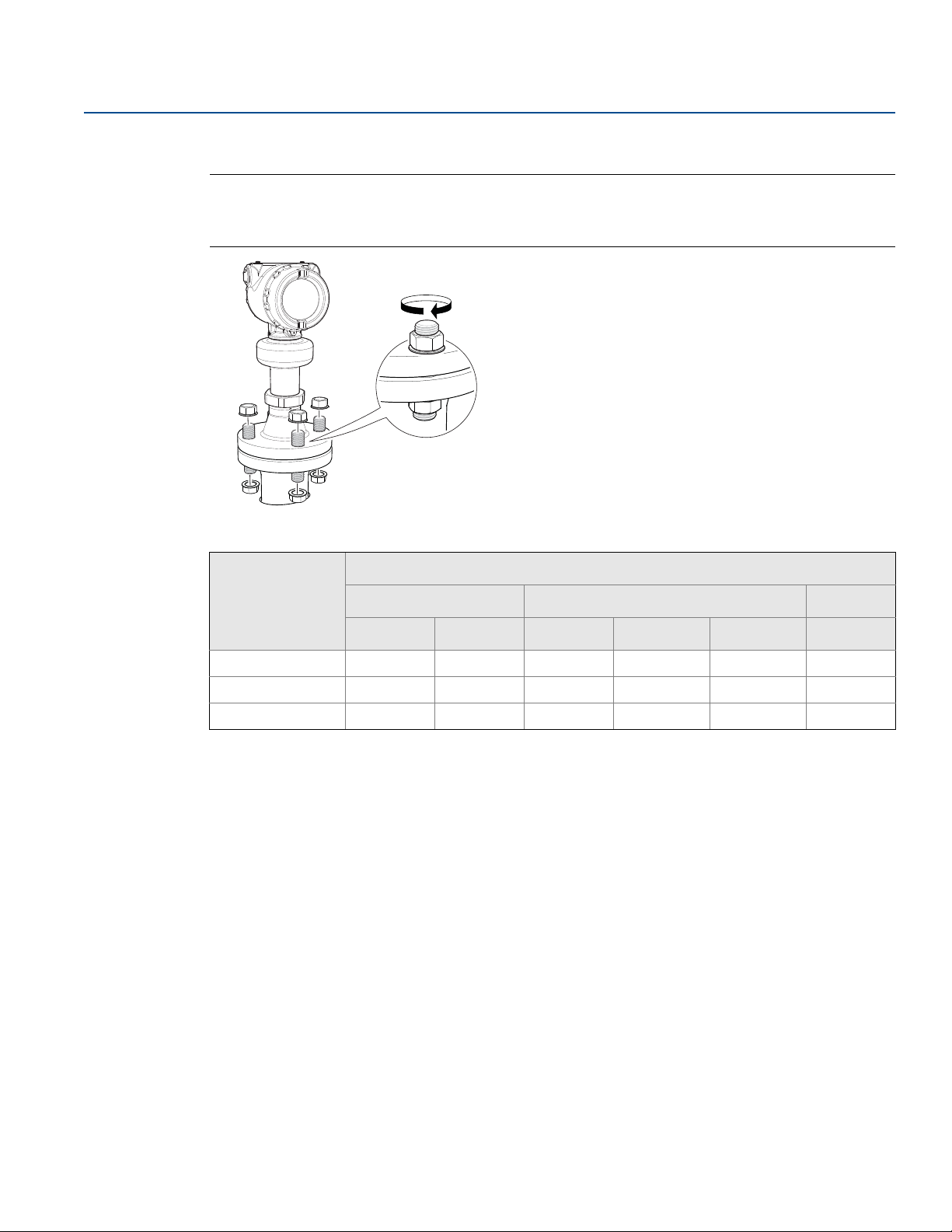
2. Tighten the bolts and nuts (see Ta bl e 3 - 8).
Note
Re-tighten after 24 hours and again after the first temperature cycle.
Check at regular intervals and re-tighten if necessary.
Reference Manual
00809-0100-4408, Rev BA
Table 3-8. Torque Value, lb-ft (N-m)
Process
(1)(2)
Process connection rating
connection size
ASME B16.5 EN1092-1 JIS B2220
Class 150 Class 300 PN6 PN10/PN16 PN25/PN40 10K
2-in./DN50/50A 29 (40) 52 (70) 15 (20) 26 (35) 29 (40) 18 (25)
3-in./DN80/80A 33 (45) 48 (65) 37 (50) 37 (50) 41 (55) 22 (30)
4-in./DN100/100A 59 (80) 52 (70) 37 (50) 37 (50) 74 (100) 26 (35)
1. The conditions used for the calculation are: Standard mating metal flange, A193 B8M Cl.2 / A4-70 bolt material, and a friction coefficient of
μ=0.16.
2. Low strength bolt and non-metallic mating flange may require lower tightening torque.
3. Align the transmitter head (see page 37).
40
Mechanical Installation
Page 53
Reference Manual
PTFE sealing
00809-0100-4408, Rev BA
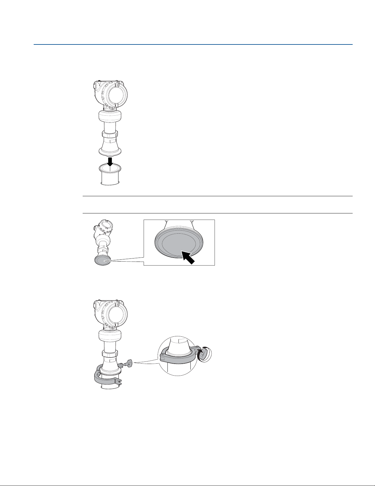
3.6.2 Tri Clamp version
1. Lower the transmitter into the nozzle.
Note
Be careful not to scratch or otherwise damage the PTFE sealing.
Mechanical Installation
November 2017
Mechanical Installation
2. Tighten the clamp to the recommended torque (see the manufacturer’s instruction manual).
3. Align the transmitter head (see page 37).
41
Page 54

Mechanical Installation
Flanged version
(see page 43)
Threaded version
(see page 44)
Welded version
(see page 48)
November 2017
3.7 Mount the parabolic antenna
Figure 3-14. Overview
Reference Manual
00809-0100-4408, Rev BA
42
Mechanical Installation
Page 55
Reference Manual
Gasket
00809-0100-4408, Rev BA
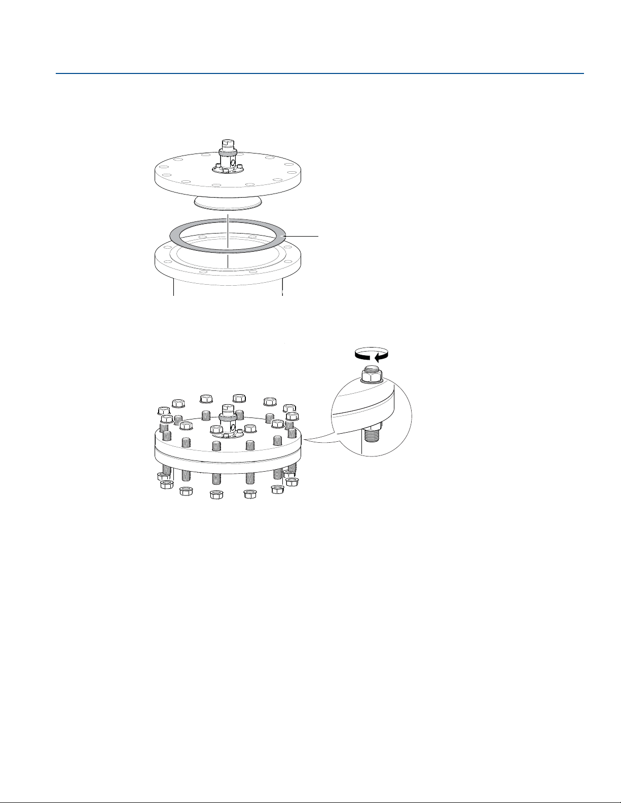
3.7.1 Flanged version
1. Lower the flange and antenna assembly into the nozzle.
2. Tighten the bolts and nuts with sufficient torque for the flange and gasket choice.
Mechanical Installation
November 2017
Mechanical Installation
3. Adjust the inclination of the antenna (see page 53).
4. Connect the air purging system (see page 56).
43
Page 56
Mechanical Installation
2x
1x
E
1x
F
1x
G
1x
D
1x
C
1x
B
1x
A
November 2017
3.7.2 Threaded version
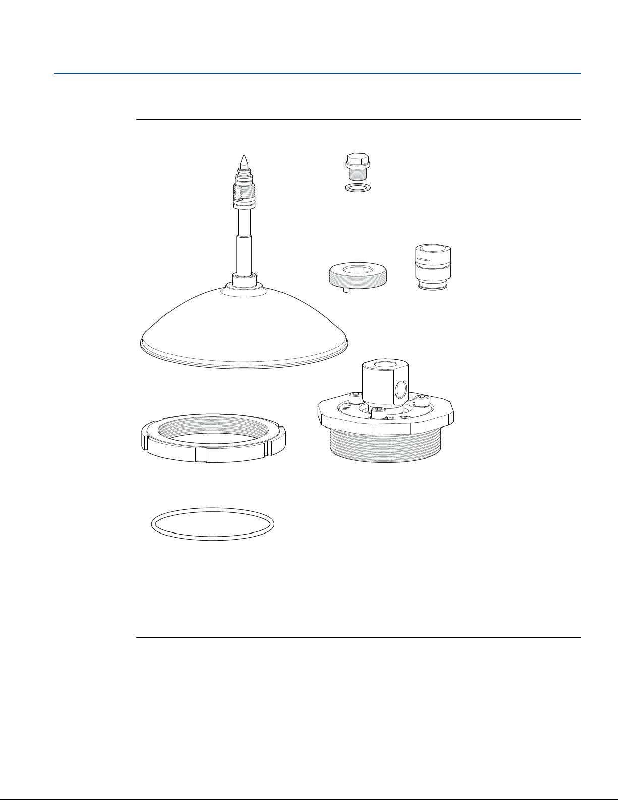
Figure 3-15. Components
Reference Manual
00809-0100-4408, Rev BA
Antenna
A.
Purge plug kit
B.
Threaded sleeve
C.
M20 adapter
D.
Lock nut BSPP (G) 3½"
E.
Antenna adapter with ball joint
F.
G.
O-ring
44
Mechanical Installation
Page 57
Reference Manual
E
F
G
Ø 3.98 ± 0.02 in.
(Ø 101 ± 0.6 mm)
OR
BSPP (G) 3½-in.
Max. 1.18 in. (30 mm)
> 0.59 in. (15 mm)
00809-0100-4408, Rev BA
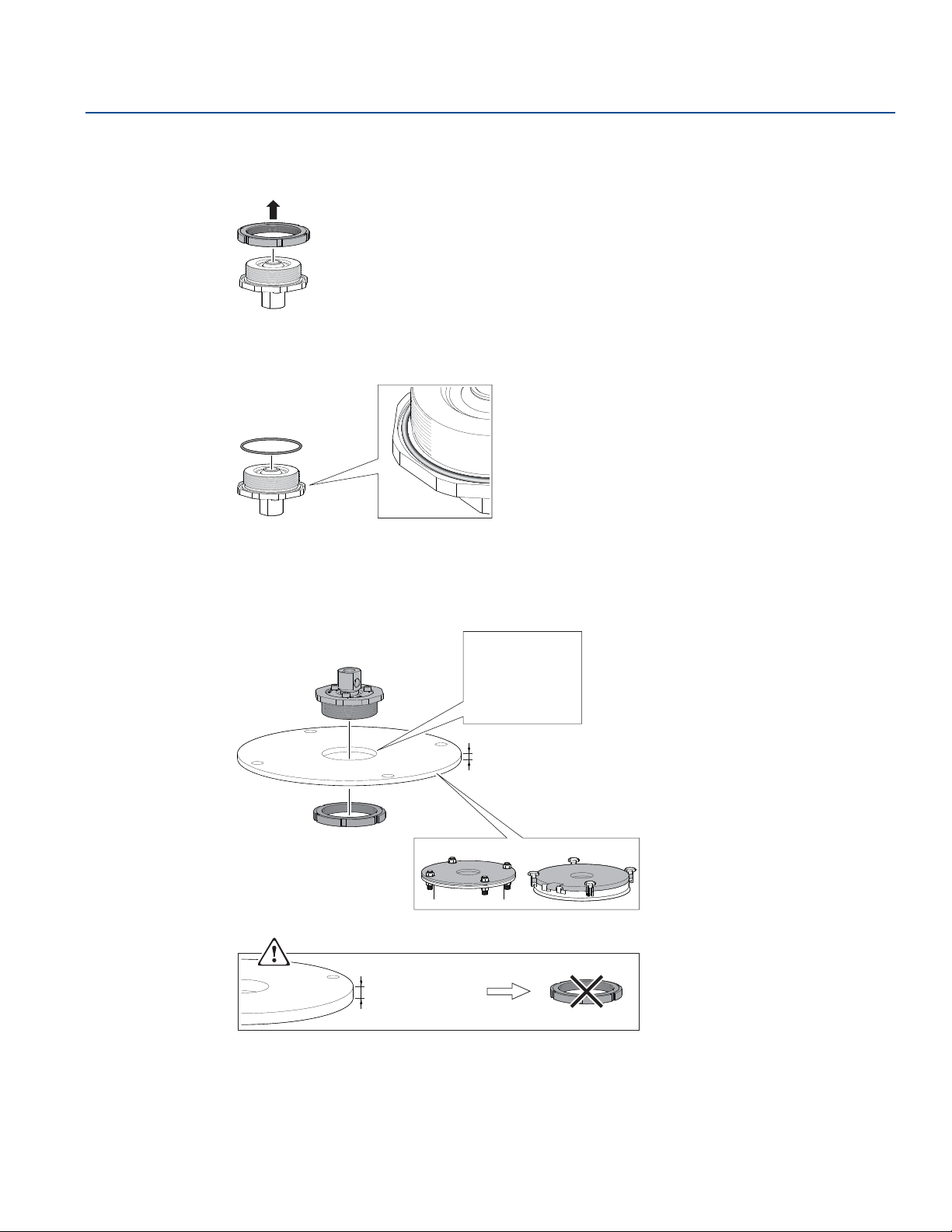
Procedure
1. Remove the lock nut.
2. Mount the O-ring.
Mechanical Installation
November 2017
3. Mount the antenna adapter on flange/manhole cover.
Ensure the antenna adapter fits tightly to the flange/manhole cover.
Mechanical Installation
45
Page 58
Mechanical Installation
O-rings
A
D
C
D
Torque 180 in-lb (20 N-m)
27 mm
November 2017
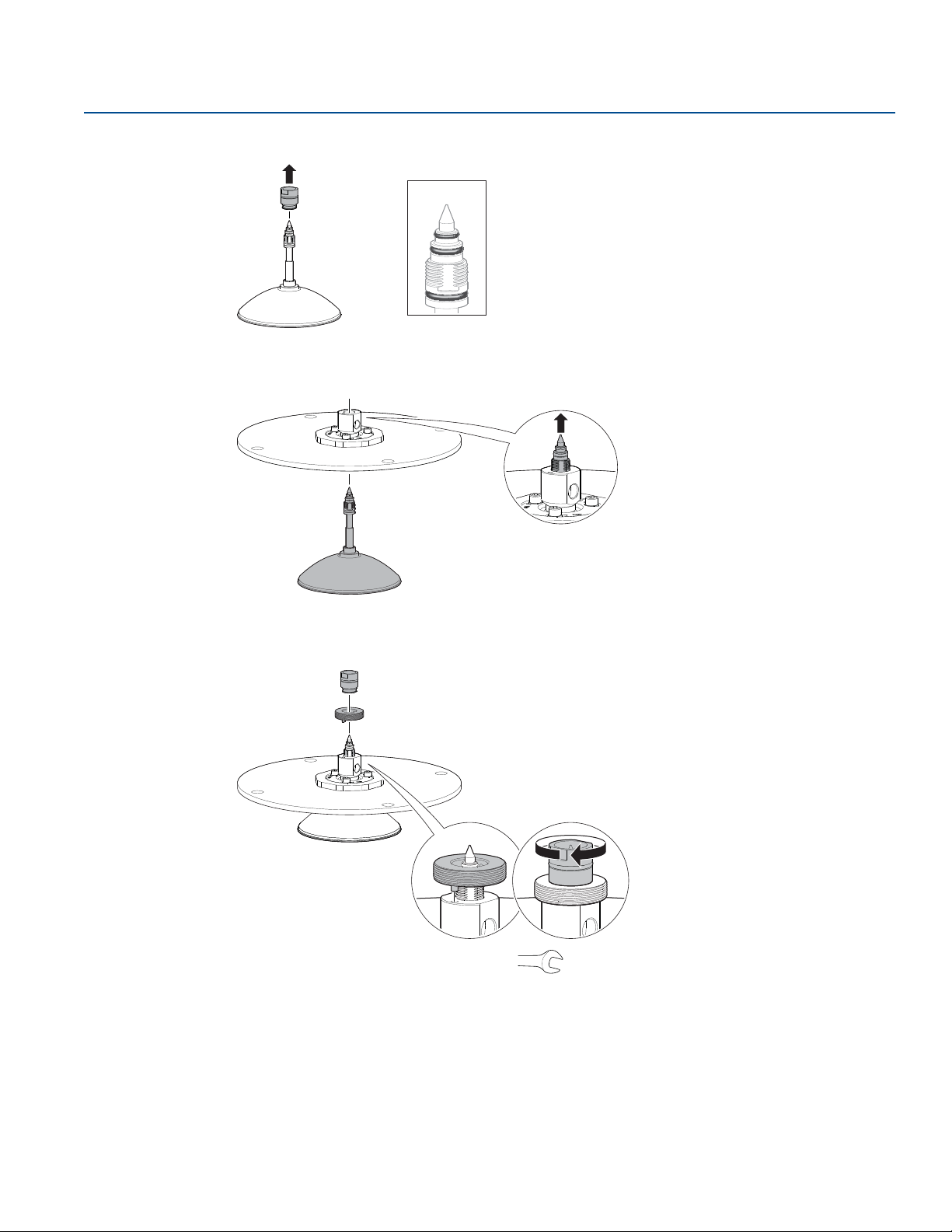
4. Remove the M20 adapter and visually inspect the O-rings for damage and dirt.
5. Carefully insert the antenna.
Reference Manual
00809-0100-4408, Rev BA
6. Secure the antenna.
46
Mechanical Installation
Page 59
Reference Manual
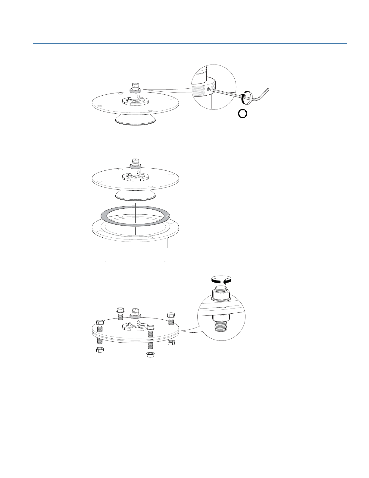
Tor que 5 in -lb (0. 5 N- m)
Gasket
00809-0100-4408, Rev BA
7. Tighten the set screw.
8. Lower the antenna assembly into the tank.
Mechanical Installation
November 2017
H2 mm
9. Tighten the bolts and nuts with sufficient torque for the flange and gasket choice.
10. Adjust the inclination of the antenna (see page 53).
11. Connect the air purging system (see page 56).
Mechanical Installation
47
Page 60
Mechanical Installation
2x
E
1x
G
1x
F
1x
H
1x
J
1x
I
1x
D
1x
C
3x
K
3x
L
1x
A
1x
B
November 2017
3.7.3 Welded version
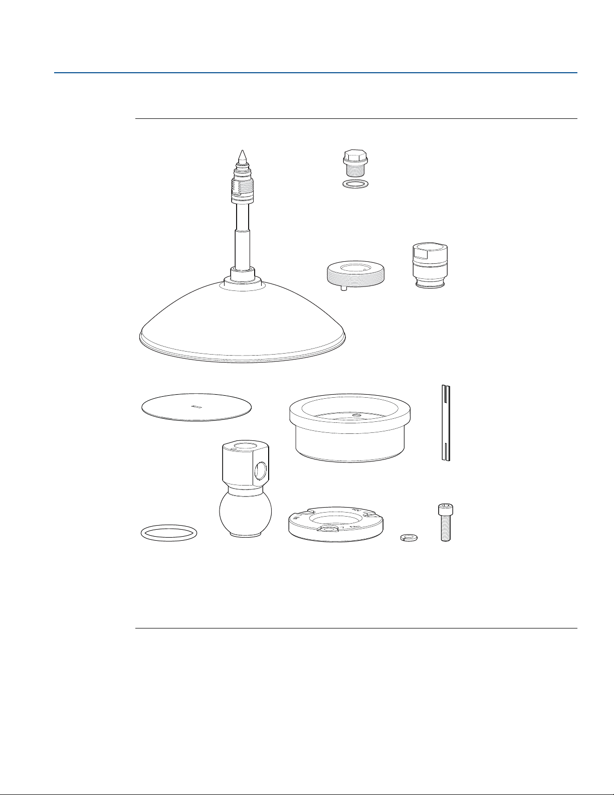
Figure 3-16. Components
Reference Manual
00809-0100-4408, Rev BA
Antenna
A.
Purge plug kit
B.
Threaded sleeve
C.
M20 adapter
D.
Weld protection plate
E.
Flange ball
F.
Weld protection bar
G.
O-ring
H.
Ball joint
I.
Clamp flange
J.
Washer
K.
M8 screw
L.
48
Mechanical Installation
Page 61
Reference Manual
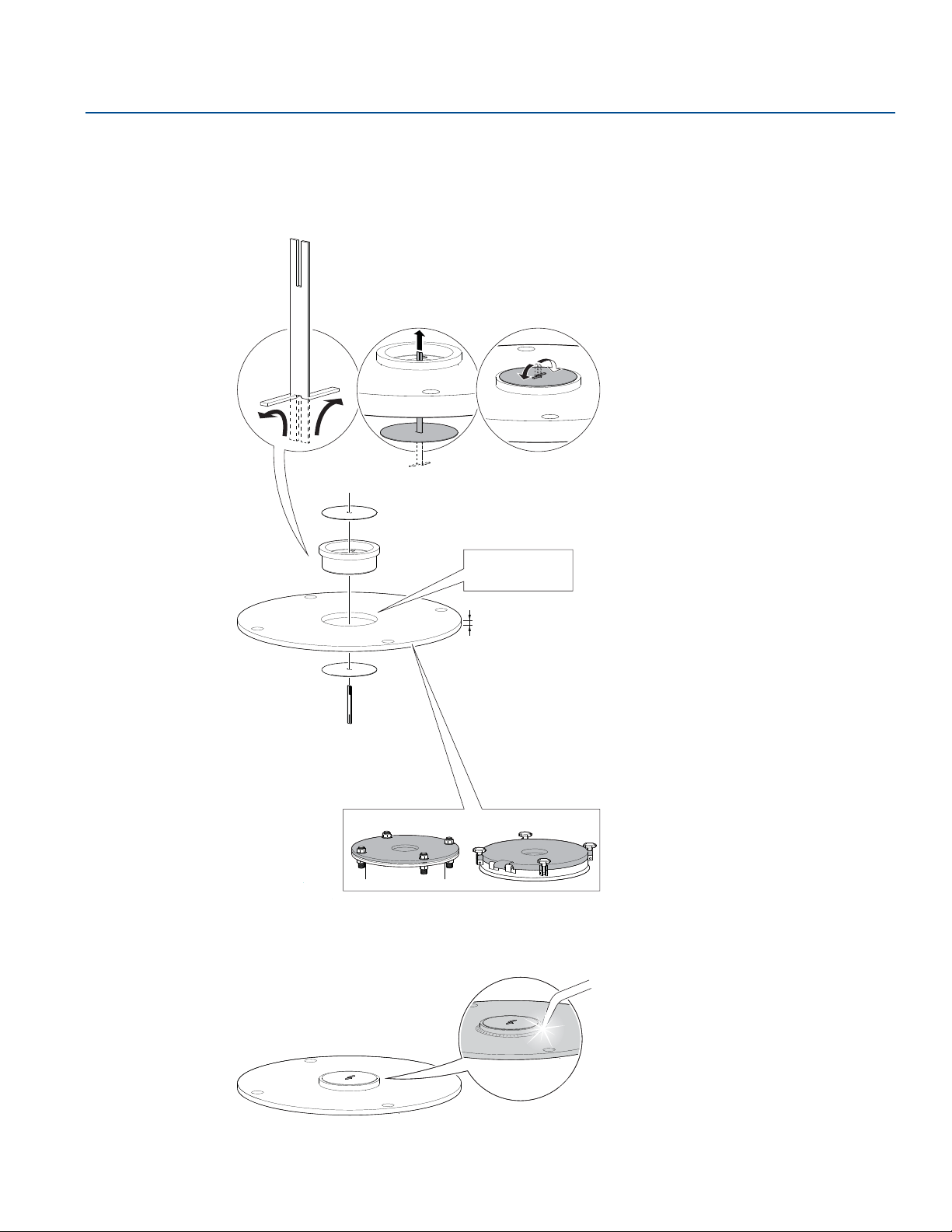
Ø 3.94 ± 0.02 in.
(Ø 100 ± 0.5 mm)
E
F
G
E
Max. 1.18 in. (30 mm)
00809-0100-4408, Rev BA
Procedure
1. Mount the protection plates to flange/manhole cover.
These plates protect the internal surfaces of the flange ball from dust and sparks during welding.
Mechanical Installation
November 2017
2. Weld the flange ball.
Mechanical Installation
49
Page 62
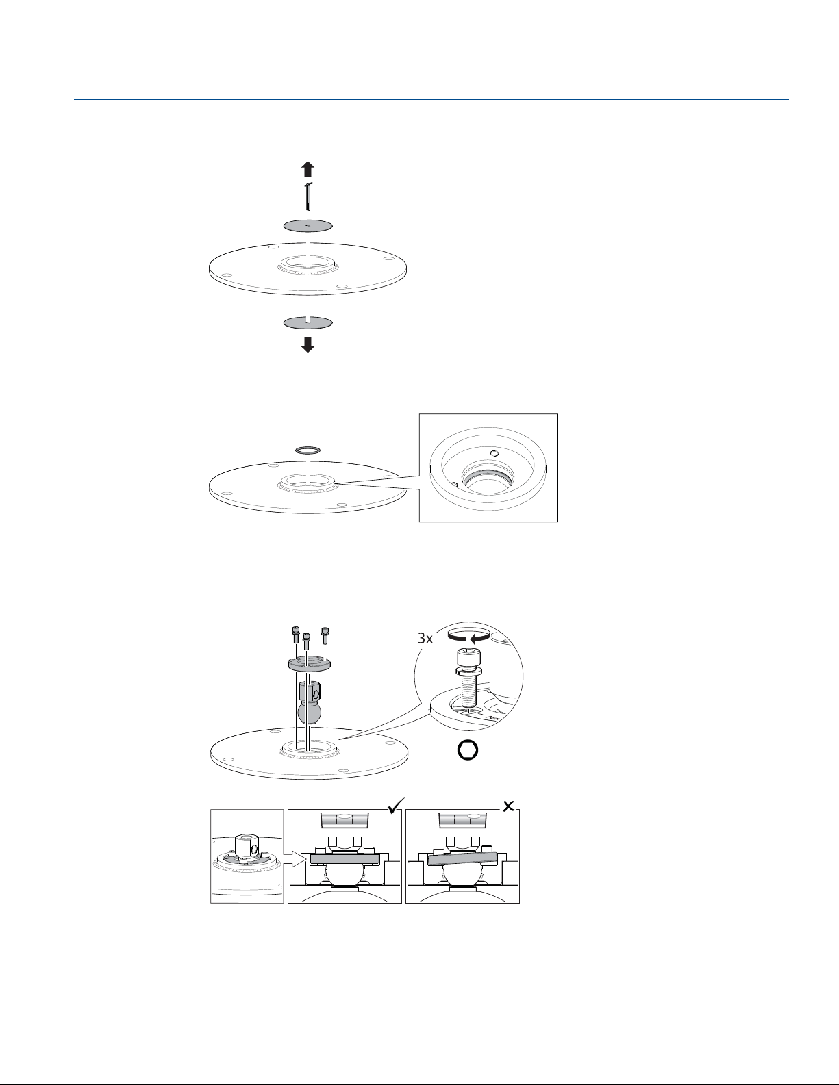
Mechanical Installation
H
H6 mm
Tor que 65 in -lb (7 N- m)
K
L
J
I
November 2017
3. Remove the protection plates and visually inspect the internal surfaces of the flange ball for damage
and dirt.
4. Mount the O-ring.
Reference Manual
00809-0100-4408, Rev BA
5. Mount the ball joint.
a. Insert the ball joint and place the clamp flange with the “7 Nm” marking side up.
b. Gradually tighten the M8 screws.
50
Mechanical Installation
Page 63
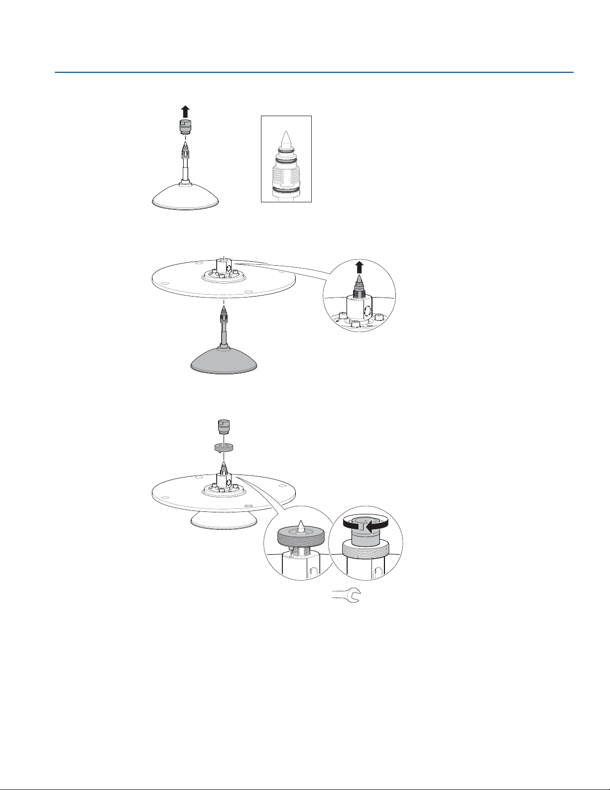
Reference Manual
O-rings
A
D
C
D
Torque 180 in-lb (20 N-m)
27 mm
00809-0100-4408, Rev BA
6. Remove the M20 adapter and visually inspect the O-rings for damage and dirt.
7. Carefully insert the antenna.
Mechanical Installation
November 2017
8. Secure the antenna.
Mechanical Installation
51
Page 64
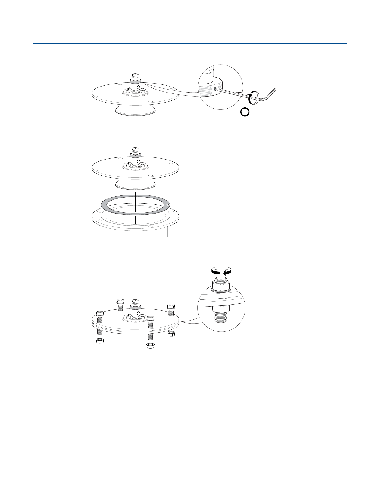
Mechanical Installation
H2 mm
Tor que 5 in- lb ( 0.5 N -m)
Gasket
November 2017
9. Tighten the set screw.
10. Lower the antenna assembly into the tank.
Reference Manual
00809-0100-4408, Rev BA
11. Tighten the bolts and nuts with sufficient torque for the flange and gasket choice.
12. Adjust the inclination of the antenna (see page 53).
13. Connect the air purging system (see page 56).
52
Mechanical Installation
Page 65
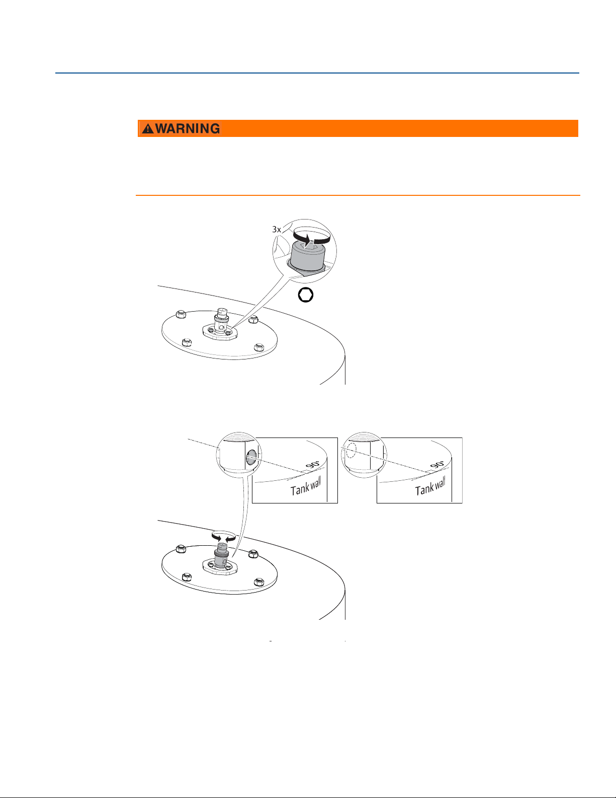
Reference Manual
or
00809-0100-4408, Rev BA
3.7.4 Adjust the inclination of the antenna
Contents may be under pressure.
Do not loosen the M8 screws while in operation. Attempting to do so may release pressurized gases,
resulting in serious injury or death.
1. Loosen the M8 screws until the antenna can rotate smoothly.
H6 mm
Mechanical Installation
November 2017
2. Rotate the antenna so the air purge connection is directed toward the tank wall.
Mechanical Installation
53
Page 66
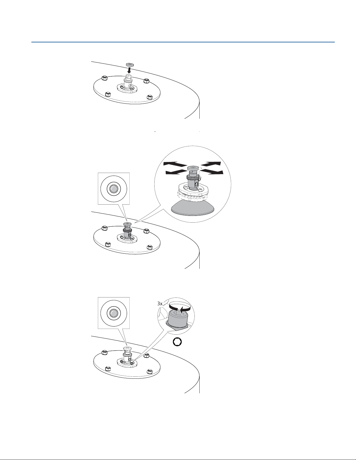
Mechanical Installation
H6 mm
Torque 65 in-lb (7 N-m)
November 2017
3. Place the circular level on top of the antenna assembly.
4. Adjust the inclination of the antenna.
Reference Manual
00809-0100-4408, Rev BA
54
5. Gradually tighten the M8 screws.
Mechanical Installation
Page 67
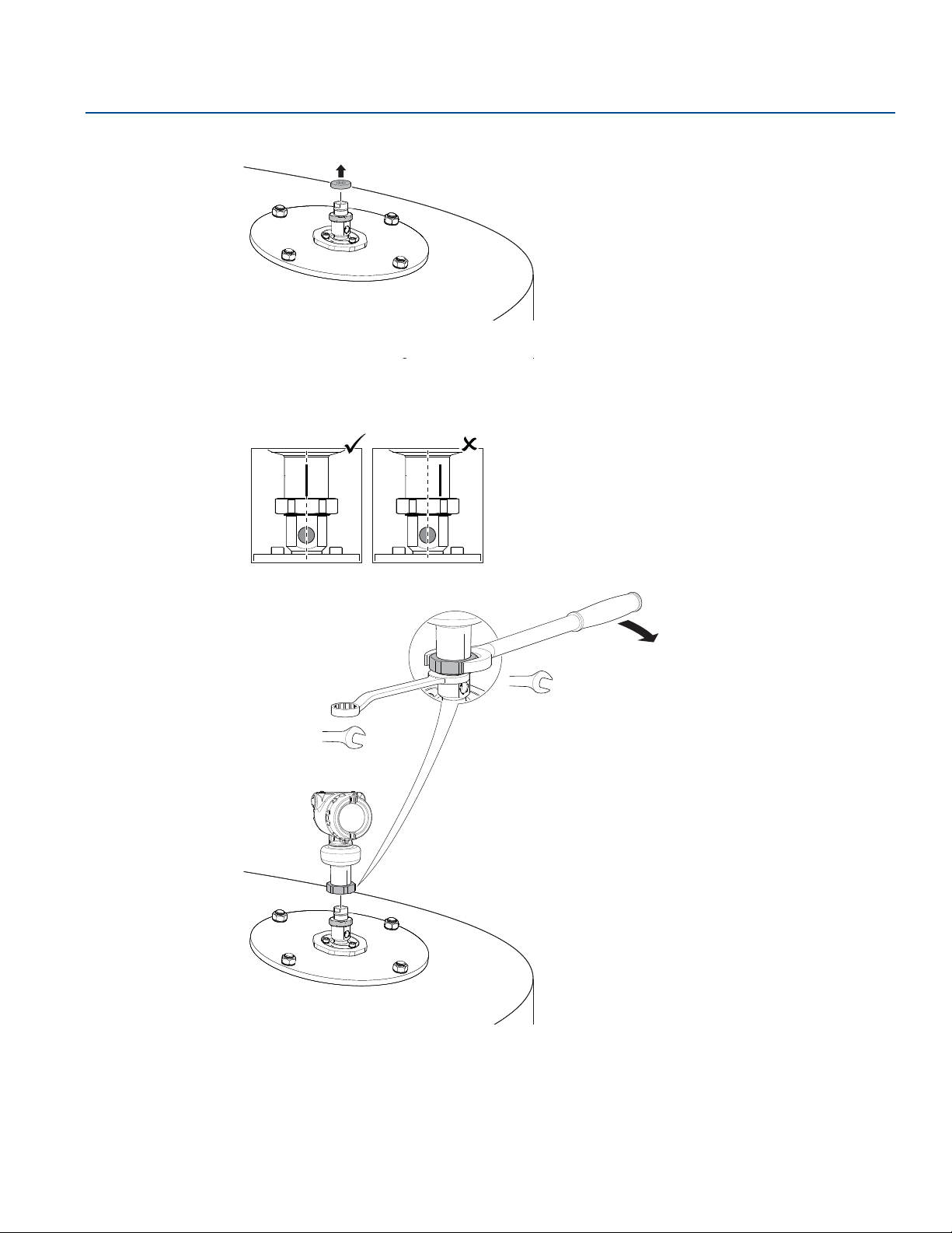
Reference Manual
60 mm
Torque 355 in-lb (40 N-m)
36 mm
00809-0100-4408, Rev BA
6. Remove the circular level.
7. Mount the transmitter head.
Align the marking on the sensor module with the air purge connection.
Mechanical Installation
November 2017
Mechanical Installation
55
Page 68
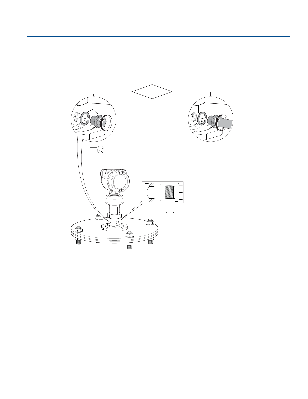
Mechanical Installation
G3/8-in.
Air purging?No Yes
0.3-0.4 in. (8-10 mm)
(gasket excluded)
Use thread sealant or
gasket according to
your site procedures.
B
Torque 180 in-lb (20 N-m)
17 mm
November 2017
3.7.5 Connect the air purging
Refer to page 142 for air supply specification. If air purging is not used, plug and seal the entry with the
purge plug kit.
Figure 3-17. Air Purging
Reference Manual
00809-0100-4408, Rev BA
56
Mechanical Installation
Page 69
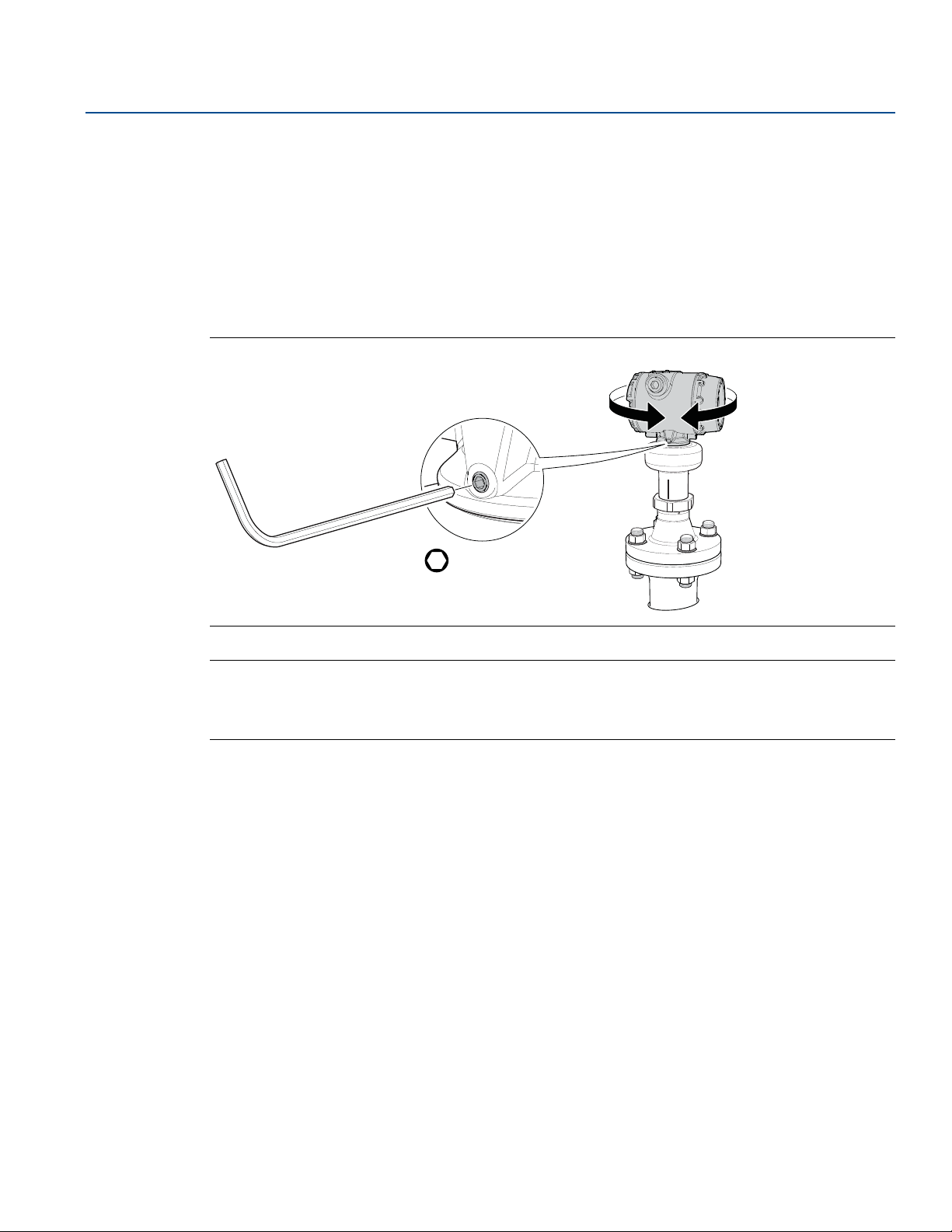
Reference Manual
Torque 30 in-lb (3 N-m)
00809-0100-4408, Rev BA
3.8 Adjust display orientation (optional)
To improve field access to wiring or to better view the optional LCD display:
1. Loosen the set screw until the transmitter housing can rotate smoothly.
2. First, rotate the housing clockwise to the desired location. If the desired location cannot be achieved
due to thread limit, rotate the housing counterclockwise to the desired location (up to 360° from
thread limit).
3. Re-tighten the set screw.
Figure 3-18. Rotate the Transmitter Housing
Mechanical Installation
November 2017
H3/32 in.
Note
In high vibration applications, the transmitter housing must be fully engaged into the sensor module to
meet the vibration test specifications. This is achieved by rotating the transmitter housing clockwise to
thread limit.
Mechanical Installation
57
Page 70

Mechanical Installation
November 2017
Reference Manual
00809-0100-4408, Rev BA
58
Mechanical Installation
Page 71

Reference Manual
00809-0100-4408, Rev BA
Section 4 Electrical Installation
Safety messages . . . . . . . . . . . . . . . . . . . . . . . . . . . . . . . . . . . . . . . . . . . . . . . . . . . . . . . . . . . . . . . . . . . . . page 59
Cable selection . . . . . . . . . . . . . . . . . . . . . . . . . . . . . . . . . . . . . . . . . . . . . . . . . . . . . . . . . . . . . . . . . . . . . . page 60
Cable gland/conduit . . . . . . . . . . . . . . . . . . . . . . . . . . . . . . . . . . . . . . . . . . . . . . . . . . . . . . . . . . . . . . . . . page 60
Power supply . . . . . . . . . . . . . . . . . . . . . . . . . . . . . . . . . . . . . . . . . . . . . . . . . . . . . . . . . . . . . . . . . . . . . . . . page 60
Hazardous areas . . . . . . . . . . . . . . . . . . . . . . . . . . . . . . . . . . . . . . . . . . . . . . . . . . . . . . . . . . . . . . . . . . . . . page 60
Wiring diagram . . . . . . . . . . . . . . . . . . . . . . . . . . . . . . . . . . . . . . . . . . . . . . . . . . . . . . . . . . . . . . . . . . . . . . page 61
Grounding . . . . . . . . . . . . . . . . . . . . . . . . . . . . . . . . . . . . . . . . . . . . . . . . . . . . . . . . . . . . . . . . . . . . . . . . . . page 62
Wiring and power up . . . . . . . . . . . . . . . . . . . . . . . . . . . . . . . . . . . . . . . . . . . . . . . . . . . . . . . . . . . . . . . . . page 63
Optional devices . . . . . . . . . . . . . . . . . . . . . . . . . . . . . . . . . . . . . . . . . . . . . . . . . . . . . . . . . . . . . . . . . . . . . page 66
4.1 Safety messages
Electrical Installation
November 2017
Procedures and instructions in this section may require special precautions to ensure the safety of the
personnel performing the operation. Information that raises potential safety issues is indicated by a
warning symbol ( ). Refer to the following safety messages before performing an operation preceded
by this symbol.
Failure to follow safe installation and service guidelines could result in death or serious injury.
Make sure the transmitter is installed by qualified personnel and in accordance with applicable code
of practice.
Use the equipment only as specified in this manual. Failure to do so may impair the protection
provided by the equipment.
For installations in hazardous locations, the transmitter must be installed according to the
Rosemount 5408 and 5408:SIS Product Certifications
document and System Control Drawing
(D7000002-885).
Explosions could result in death or serious injury.
Verify that the operating environment of the transmitter is consistent with the appropriate
hazardous locations certifications.
Before connecting a Field Communicator in an explosive atmosphere, make sure the instruments in
the loop are installed in accordance with intrinsically safe or non-incendive field wiring practices.
Do not remove the transmitter covers in explosive atmospheres when the circuit is alive.
Both transmitter covers must be fully engaged to meet explosion-proof requirements.
Electrical shock can result in death or serious injury.
Avoid contact with the leads and terminals. High voltage that may be present on leads can cause
electrical shock.
Make sure the main power to the transmitter is off and the lines to any other external power source
are disconnected or not powered while wiring the transmitter.
Electrical Installation
59
Page 72
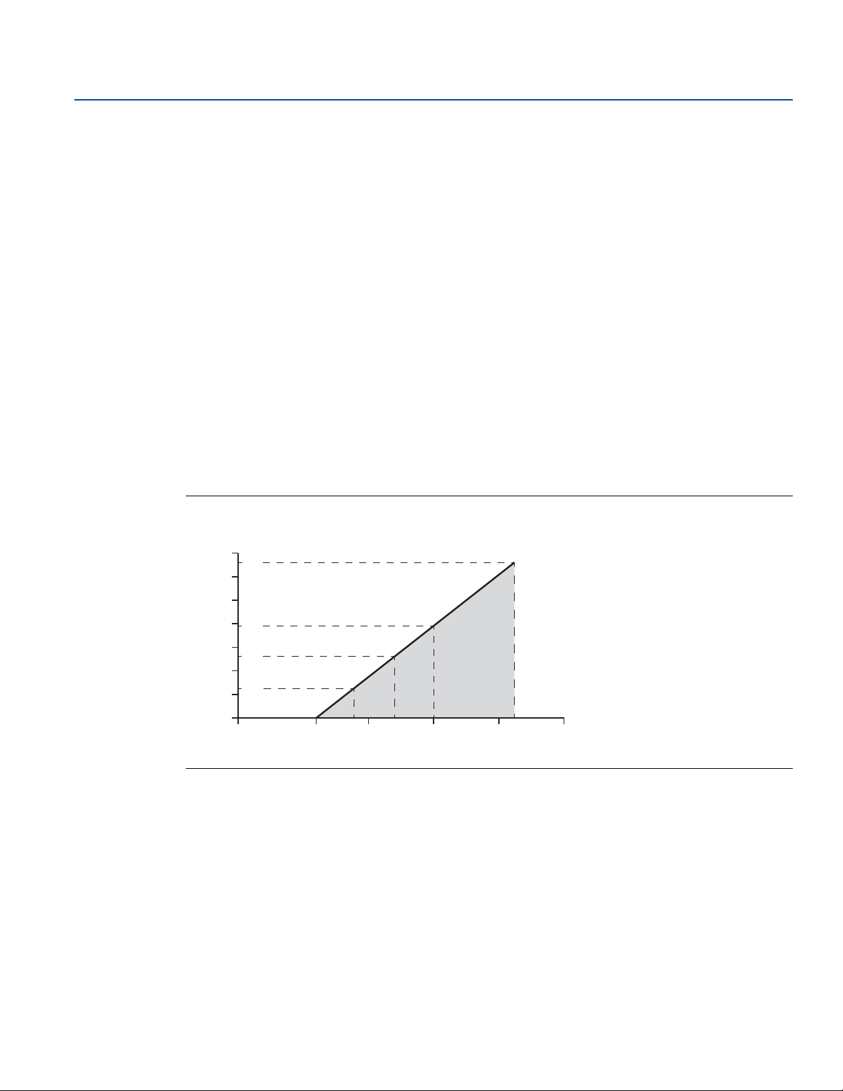
Electrical Installation
42.4
2417.8
12
0
400
200
1000
800
600
1200
1400
20 30 40 50
521
250
782
1322
External Power Supply Voltage (Vdc)
Loop Resistance (Ohms)
Maximum Loop Resistance = 43.5 * (External Power Supply Voltage - 12)
November 2017
4.2 Cable selection
Use 24-14 AWG wire. Twisted pairs and shielded wiring are recommended for environments with high
EMI (electromagnetic interference).
The cables must be suitable for the supply voltage and approved for use in hazardous areas, where
applicable. Two wires can be safely connected to each terminal screw.
4.3 Cable gland/conduit
For explosion-proof/flameproof installations, only use cable glands or conduit entry devices certified
explosion-proof or flameproof.
4.4 Power supply
The transmitter operates on 12-42.4 Vdc (12-30 Vdc in Intrinsically Safe installations) at the transmitter
terminals.
For HART
determined by the voltage level of the external power supply, as described by Figure 4-1.
®
communication, a minimum loop resistance of 250 is required. Maximum loop resistance is
Reference Manual
00809-0100-4408, Rev BA
Figure 4-1. Load Limits
4.5 Hazardous areas
When the transmitter is installed in hazardous areas, local regulations, and specifications in applicable
certificates must be observed. See Appendix B: Product Certifications for more information.
60
Electrical Installation
Page 73
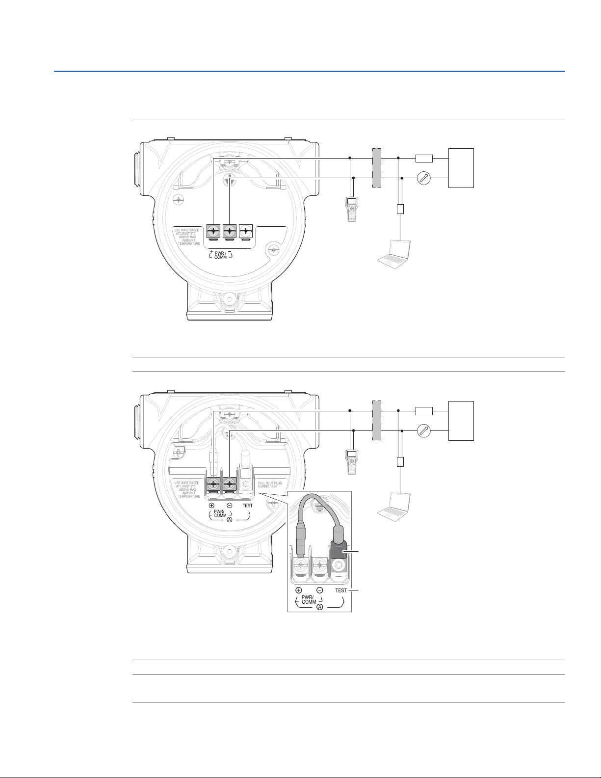
Reference Manual
00809-0100-4408, Rev BA
4.6 Wiring diagram
Figure 4-2. 4-20 mA/HART Communication
Electrical Installation
November 2017
+
D
F
+
-
B
123
456
7809
C
-
E
A
Load resistance (≥250
Field Communicator
A.
Approved IS barrier (for Intrinsically Safe installations only)
B.
HART modem
C.
D.
Current meter
E.
Power supply
F.
Figure 4-3. 4-20 mA/HART Communication - Terminal Block with TEST Terminal
+
D
-
B
123
456
7809
E
C
A
F
+
-
(1)
G
H
Current meter
Field Communicator
A.
Approved IS barrier (for Intrinsically Safe installations only)
B.
HART modem
C.
Load resistance (≥250
D.
E.
Power supply
F.
Blue plug
G.
TEST terminal
H.
Note
Blue plug must only be disconnected during loop current measurement procedure.
1. Applicable for Rosemount 5408:SIS and Rosemount 5408 with option code EF1 (ready for upgrade to Rosemount 5408:SIS).
Electrical Installation
61
Page 74
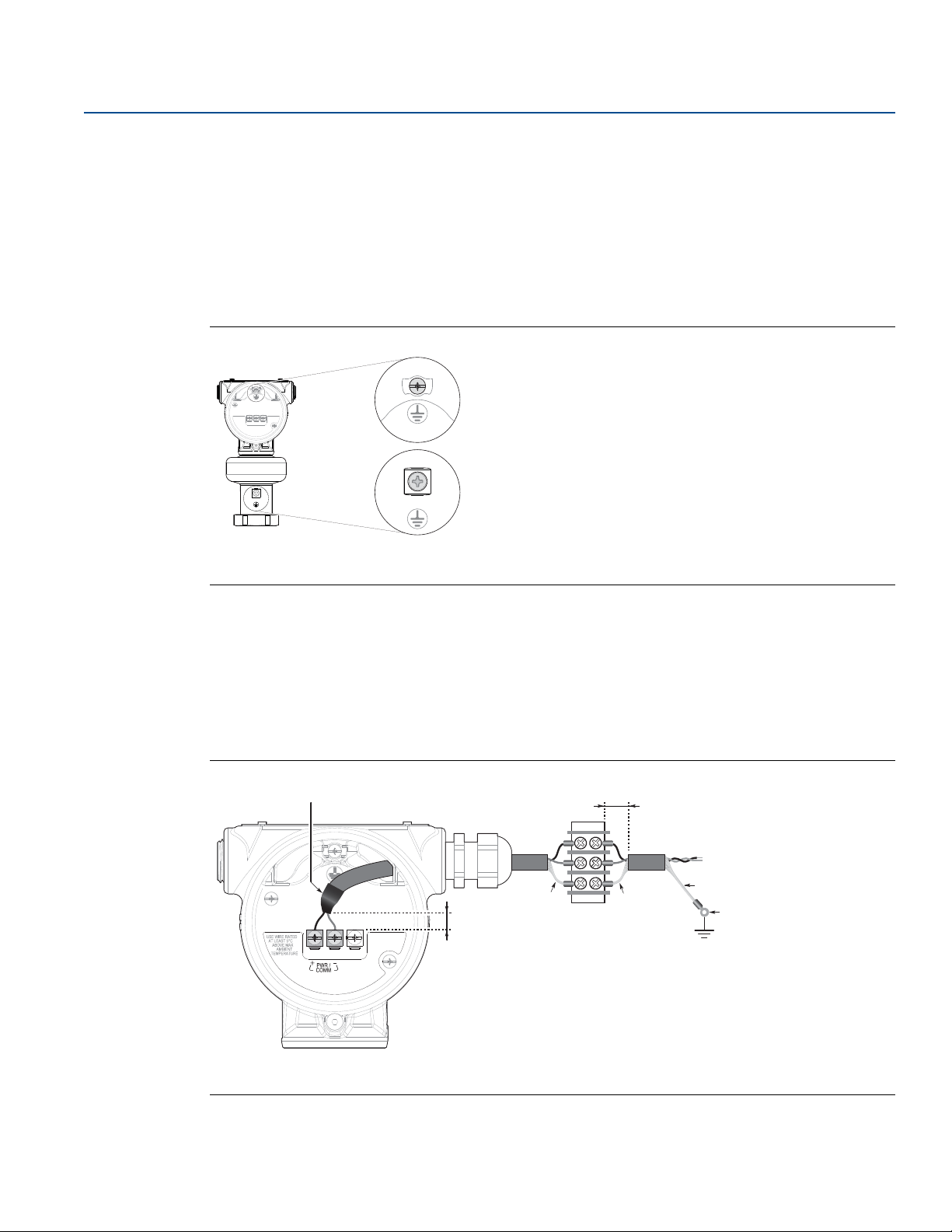
Electrical Installation
A
B
B
BA
CC
C
D
November 2017
4.7 Grounding
Make sure grounding is done according to national and local electrical codes. Failure to do so may impair
the protection provided by the equipment.
4.7.1 Transmitter housing
The most effective grounding method is direct connection to earth ground with minimal impedance.
There are two grounding screw connections provided (see Figure 4-4).
Figure 4-4. Ground Screws
Reference Manual
00809-0100-4408, Rev BA
A.B.Internal ground screw
External ground screw
4.7.2 Signal cable shield grounding
Make sure the instrument cable shield is:
Trimmed close and insulated from touching the transmitter housing.
Continuously connected throughout the segment.
Connected to a good earth ground at the power supply end.
Figure 4-5. Cable Shield
62
A.B.Insulate shield
Minimize distance
C.D.Trim shield and insulate
Connect shield back to the power supply ground
Electrical Installation
Page 75
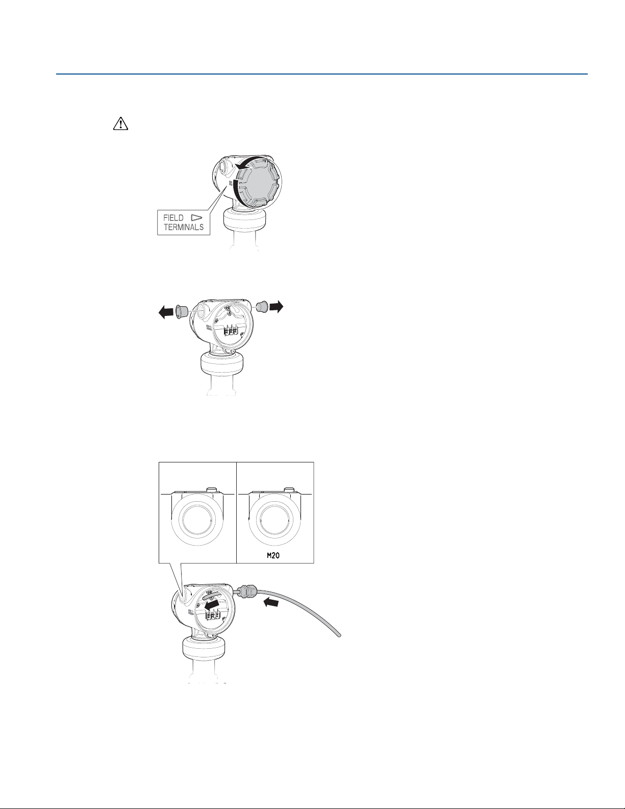
Reference Manual
½-14 NPT M20 x 1.5
Identification of thread size and type
00809-0100-4408, Rev BA
4.8 Wiring and power up
1. Verify the power supply is disconnected.
2. Remove the cover.
3. Remove the plastic plugs.
Electrical Installation
November 2017
4. Pull the cable through the cable gland/conduit.
(1)
1. Unless marked, the conduit/cable entries in the transmitter housing use a ½–14 NPT thread form.
Electrical Installation
63
Page 76
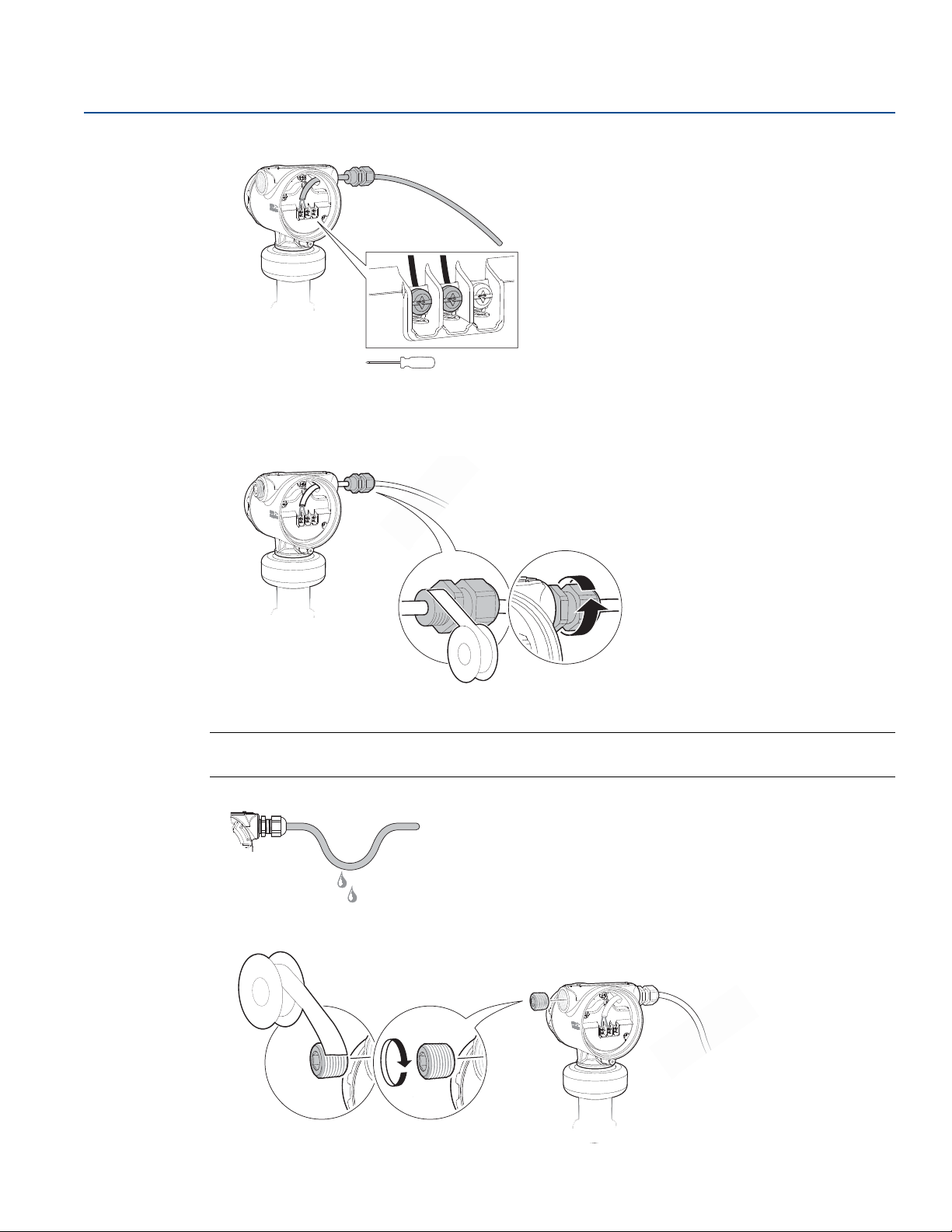
Electrical Installation
Tor que 7 in- lb ( 0.8 N -m)
PTFE tape or other sealant
PTFE tape or other sealant
November 2017
5. Connect the cable wires (see “Wiring diagram” on page 61).
6. Ensure proper grounding (see“Grounding” on page 62).
7. Tighten the cable gland.
Reference Manual
00809-0100-4408, Rev BA
64
Note
Make sure to arrange the wiring with a drip loop.
8. Seal any unused ports with the enclosed metal plug.
Electrical Installation
Page 77
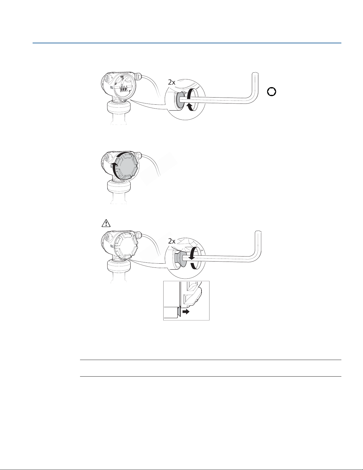
Reference Manual
Cover jam screw
(one per side)
00809-0100-4408, Rev BA
9. Attach and tighten the covers. Make sure the covers are fully engaged.
a. Verify the cover jam screws are completely threaded into the housing.
b. Attach and tighten the covers.
Electrical Installation
November 2017
H2.5 mm
c. Turn the jam screw counterclockwise until it contacts the cover.
Required for explosion-proof/flameproof installations only.
d. Turn the jam screw an additional ½ turn counterclockwise to secure the cover.
10. Connect the power supply.
Note
It may take up to 15 seconds before the LCD display lights up.
Electrical Installation
65
Page 78
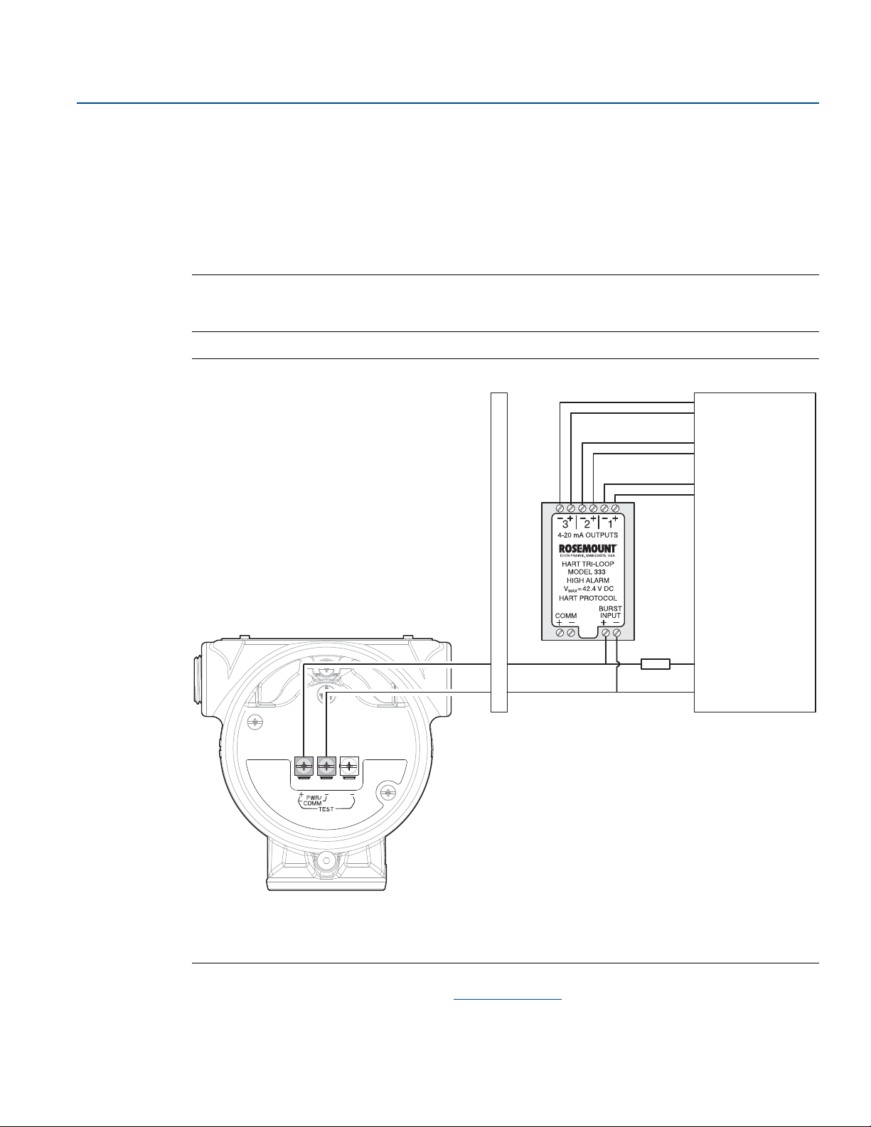
Electrical Installation
-
+
+
+
+
-
+
B
AD
C
PV
SV
TV
QV
Each Tri-Loop
channel receives
power from
control room
Channel 1 must
be powered for
the Tri-Loop to
operate
Rosemount 5408
receives power
from control
room
November 2017
4.9 Optional devices
Reference Manual
00809-0100-4408, Rev BA
4.9.1 Rosemount™ 333 HART Tri-Loop
The Rosemount 5408 and 5408:SIS Level Transmitters output a HART signal with four process variables.
By using the Rosemount 333 HART Tri-Loop, up to three additional analog 4-20 mA outputs are
provided.
Note
The operational mode on the Rosemount 5408:SIS must be set to Control/Monitoring when used with
the Rosemount 333 HART Tri-Loop.
Figure 4-6. Example Installation of Rosemount 333 with Rosemount 5408
™
Approved IS barrier
A.
DIN rail mounted Rosemount 333
B.
Load resistance (≥250
C.
Control room
D.
Refer to the Rosemount 333 HART Tri-Loop Reference Manual for further information on how to install
and configure the Rosemount 333.
66
Electrical Installation
Page 79

Reference Manual
00809-0100-4408, Rev BA
Section 5 Configuration
Safety messages . . . . . . . . . . . . . . . . . . . . . . . . . . . . . . . . . . . . . . . . . . . . . . . . . . . . . . . . . . . . . . . . . . . . . page 67
Overview . . . . . . . . . . . . . . . . . . . . . . . . . . . . . . . . . . . . . . . . . . . . . . . . . . . . . . . . . . . . . . . . . . . . . . . . . . . page 67
System readiness . . . . . . . . . . . . . . . . . . . . . . . . . . . . . . . . . . . . . . . . . . . . . . . . . . . . . . . . . . . . . . . . . . . . page 68
Get started with your preferred configuration tool . . . . . . . . . . . . . . . . . . . . . . . . . . . . . . . . . . . . . . . page 68
Confirm HART revision capability . . . . . . . . . . . . . . . . . . . . . . . . . . . . . . . . . . . . . . . . . . . . . . . . . . . . . . page 70
Configure device using Guided Setup . . . . . . . . . . . . . . . . . . . . . . . . . . . . . . . . . . . . . . . . . . . . . . . . . . page 71
Verify Level . . . . . . . . . . . . . . . . . . . . . . . . . . . . . . . . . . . . . . . . . . . . . . . . . . . . . . . . . . . . . . . . . . . . . . . . . page 72
Establish multidrop communication . . . . . . . . . . . . . . . . . . . . . . . . . . . . . . . . . . . . . . . . . . . . . . . . . . . page 73
Use with the Rosemount 333 HART Tri-Loop™ . . . . . . . . . . . . . . . . . . . . . . . . . . . . . . . . . . . . . . . . . . . page 74
5.1 Safety messages
Configuration
November 2017
Procedures and instructions in this section may require special precautions to ensure the safety of the
personnel performing the operation. Information that raises potential safety issues is indicated by a
warning symbol ( ). Refer to the following safety messages before performing an operation preceded
by this symbol.
Explosions could result in death or serious injury.
Verify that the operating environment of the transmitter is consistent with the appropriate
hazardous locations certifications.
Before connecting a Field Communicator in an explosive atmosphere, make sure the instruments in
the loop are installed in accordance with intrinsically safe or non-incendive field wiring practices.
Do not remove the transmitter covers in explosive atmospheres when the circuit is alive.
Both transmitter covers must be fully engaged to meet explosion-proof requirements.
Electrical shock can result in death or serious injury.
Avoid contact with the leads and terminals. High voltage that may be present on leads can cause
electrical shock.
5.2 Overview
This chapter provides information about configuration and configuration tools. Appendix C:
Configuration Parameters provides extended information about the configuration parameters. The
menu trees can be found in section “Menu tree” on page 185.
Config uration
67
Page 80

Configuration
November 2017
5.3 System readiness
5.3.1 Confirm correct device driver
The transmitter meets the NAMUR recommendation NE 53. Verify the latest Device Descriptor (DD) or
FDI Package is loaded on your systems to ensure proper communication.
1. Within Ta b l e 5 - 1 , use the HART
DD or FDI Package.
®
Universal Revision and Device Revision numbers to find the correct
Reference Manual
00809-0100-4408, Rev BA
2. Download the latest DD at EmersonProcess.com/DeviceFiles
3. Download the latest FDI Package at Emerson.com/RosemountRadarMasterPlus
.
.
Table 5-1. Identification and Compatibility According to NAMUR NE 53
Release
date
NAMUR hardware
revision
March-17 1.0.xx 1.0.xx 1.Axx 6 1 00809-0100-4408 N/A
1. NAMUR Revision is located on the transmitter label. Differences in level 3 changes, signified above by xx, represent minor product changes as defined per NE53.
Compatibility and functionality are preserved and product can be used interchangeably.
2. Device software revision is located on the transmitter label, e.g. 1.A3. It ca n also be fou nd in Rosemou nt Radar Master Plus (under Overview, select Device Information
> Revision s).
3. HART Revision 6 and 7 can be switched in field. Default HART universal revision from fac tory is located on the transmitter head label, e.g. PROTOCOL 6.
4. Device revision is located on the transmitter label, e.g. DEVICE REV 1.
Device identification DD and FDI identification Review
(1)
NAMUR software
revision
(1)
Device software
revision
(2)
HART® universal
(3)
revision
7 1
Device
revision
Manual document
(4)
instructions
number
Review
functionality
Change
description
5.4 Get started with your preferred configuration tool
The Rosemount™ 5408 and 5408:SIS Level Transmitters can easily be configured by using:
Rosemount Radar Master Plus (running in the Instrument Inspector
Device Descriptor (DD) based systems, e.g. AMS Device Manager, 475 Field Communicator, AMS Trex
Device Communicator, and DeltaV
Field Device Integration (FDI) based systems
™
, or any other EDDL or enhanced-EDDL host
™
Application)
™
Rosemount Radar Master Plus is the recommended tool for configuration.
5.4.1 Rosemount Radar Master Plus
The Rosemount Radar Master Plus is a user-friendly software package that includes basic configuration
options, as well as advanced configuration and service functions. The Instrument Inspector Application
or any FDI compliant host is needed to run Rosemount Radar Master Plus.
Instrument Inspector is shipped with every transmitter. See the CD installation guide for a list of
supported HART modems and system requirements.
Instrument Inspector is also available at:
Emerson.com/InstrumentInspector
68
Configuration
Page 81

Reference Manual
00809-0100-4408, Rev BA
Get the latest FDI Package
The Rosemount 5408 FDI Package is typically installed together with Instrument Inspector. If the FDI
Package is not installed, it can be found on the enclosed CD. The latest FDI Package can also be
downloaded from:
Emerson.com/RosemountRadarMasterPlus
After downloading, add the FDI Package to Instrument Inspector:
1. Start Instrument Inspector.
2. From the menu bar, select , and then select Add Device Package.
3. Browse to the downloaded FDI Package and select Open.
4. Select Add.
5. Select Back.
5.4.2 AMS Device Manager
Get the latest Device Descriptor (DD)
Configuration
November 2017
The Device Descriptor (DD) is a configuration tool that is developed to assist the user through the
configuration. The Rosemount 5408 DD is typically installed together with AMS Device Manager.
To download the latest DD, visit the Emerson
EmersonProcess.com/devicefiles
After downloading, add the DD to AMS Device Manager:
1. Close AMS Device Manager.
2. Click the Start button, and then select All Programs > AMS Device Manager > Add Device Type.
3. Browse to the downloaded DD files and select OK.
In the Add Device Type application, select the Help button for more information on how to complete this
operation.
™
Device Install Kit site at:
Configure the HART modem interface
Before connecting to the device using a HART modem, the HART modem interface must be configured
in AMS Device Manager:
1. Close AMS Device Manager.
2. Click the Start button, and then select All Programs > AMS Device Manager > Network
Configuration.
3. Select Add.
4. In the drop down list, select HART modem and select Install.
Config uration
5. Follow the on-screen instructions.
In the Network Configuration application, select the Help button for more information on how to
complete this operation.
69
Page 82

Configuration
November 2017
5.4.3 Field Communicator
Get the latest Device Descriptor (DD)
If the DD is not installed in your Field Communicator, see the appropriate Field Communicator User’s
Manual available at Emerson.com/FieldCommunicator
Communicator with the latest DD.
for instructions on how to update the Field
5.5 Confirm HART revision capability
If using HART based control or asset management systems, confirm the HART capability of those
systems prior to transmitter installation. Not all systems are capable of communicating with HART
Revision 7 protocol. This transmitter can be configured for either HART Revision 6 or Revision 7.
5.5.1 Switch HART revision mode
If the HART configuration tool is not capable of communicating with HART Revision 7, the device will
load a generic menu with limited capability.
To switch the HART revision mode from the generic menu:
Reference Manual
00809-0100-4408, Rev BA
1. Locate the “Message” field.
2. In the Message field, enter HART6 or HART7 and then 27 trailing spaces.
70
Configuration
Page 83
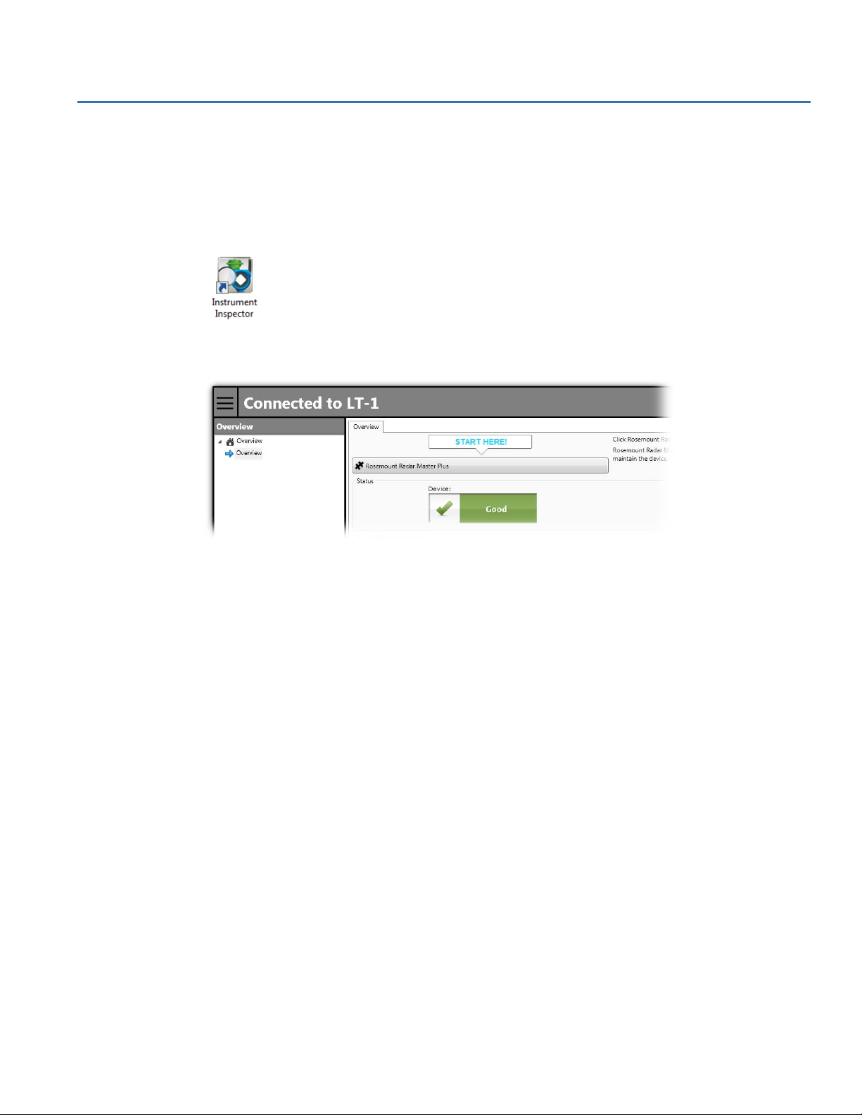
Reference Manual
00809-0100-4408, Rev BA
5.6 Configure device using Guided Setup
The options available in the Guided Setup wizard include all items required for basic operation. All basic
configuration parameters are described in Appendix C: Configuration Parameters.
Rosemount Radar Master Plus
1. Start Instrument Inspector Application.
2. Under HART, double-click the device icon.
3. From the Overview screen, select Rosemount Radar Master Plus.
Configuration
November 2017
4. Under Configure, select Guided Setup and follow the on-screen instructions.
AMS Device Manager
1. Start AMS Device Manager.
2. Select View > Device Connection View.
3. In the Device Connection View, double-click the HART modem icon.
4. Double-click the device icon.
5. Select Configure > Guided Setup.
6. Select Basic Setup and follow the on-screen instructions.
Field Communicator
1. Turn on the Field Communicator and connect to the device.
2. Select Configure > Guided Setup.
3. Select Basic Setup and follow the on-screen instructions.
Config uration
71
Page 84
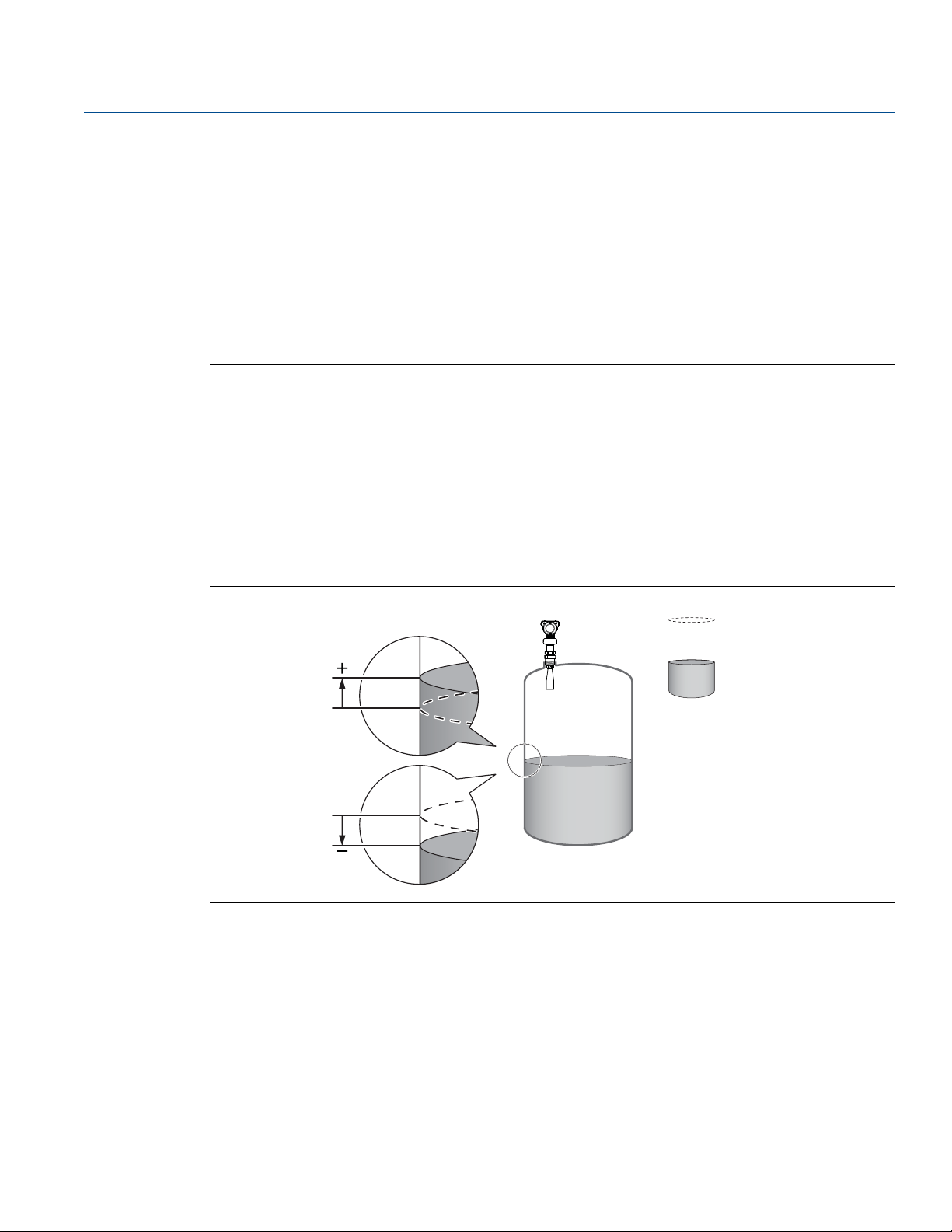
Configuration
Reported level
Actual level
Positive Calibration
Offset value
Negative Calibration
Offset value
November 2017
5.7 Verify Level
Run the Verify Level tool to match the product level reported by the device to a reference measurement
(measured by using for example handgauging).
If any difference, the Calibration Offset parameter will be adjusted as shown in Figure 5-1. A minor
adjustment using Calibration Offset is normal. There may, for example, be a deviation between the
actual tank height and the configured value.
Note
Before running Verify Level, make sure that: the product surface is calm, the tank is not being filled or
emptied, and the actual level is well above the tank bottom.
Verify Level is included as part of the Guided Setup wizard. The tool is also available as follows:
Rosemount Radar Master Plus
1. Under Configure, select Verify Level to check your level measurement, and follow the on-screen
instructions.
AMS Device Manager and Field Communicator
Reference Manual
00809-0100-4408, Rev BA
1. Select Configure > Guided Setup.
2. Select Verify Level to check your level measurement, and follow the on-screen instructions.
Figure 5-1. Calibration Offset
72
Configuration
Page 85

Reference Manual
00809-0100-4408, Rev BA
5.8 Establish multidrop communication
Multidropping transmitters refers to the connection of several transmitters to a single communications
transmission line. Communication between the host and the transmitters takes place digitally with the
analog output of the transmitters deactivated.
In multidrop communication, each transmitter in the loop must have a unique HART address.
Rosemount Radar Master Plus
1. Under Configure, select Device Setup > HART.
2. Under Communication Interface, select HART Multidrop.
3. In the HART Address box, type or select the HART address you want to use.
4. Select Save.
AMS Device Manager
1. Select Configure > Manual Setup > Device Setup > HART.
2. Select Change Address, and then type the HART address you want to use.
Configuration
November 2017
3. Select Next.
4. Select Finish when the Method Complete message appears.
5. Ensure the Multidrop check box is selected.
Field Communicator
1. Select Configure > Manual Setup > Device Setup > HART.
2. Select Change Address.
3. Type the HART address you want to use, and then select ENTER.
4. Ensure Multidrop is set to “ON”.
Config uration
73
Page 86

Configuration
November 2017
Reference Manual
00809-0100-4408, Rev BA
5.9 Use with the Rosemount 333 HART Tri-Loop
To prepare the transmitter for use with a Rosemount 333 HART Tri-Loop, the transmitter must be
configured to Burst Mode and the process variable output order must be set.
AMS Device Manager and Field Communicator
1. Make sure the transmitter is properly configured.
2. If desired, change the measurement units.
Select Configure > Manual Setup > Device Setup > Units.
3. Set the desired transmitter variable to use for Primary Variable (PV), Secondary Variable (SV), Third
Variable (TV), and Fourth Variable (QV).
a. Select Configure > Manual Setup > Device Setup > HART.
b. Under Variable Mapping, select variables for PV, SV, TV, and QV.
4. Set the Rosemount 5408 to Burst Mode.
HART Revision 6: HART Revision 7:
a. Select Configure Burst Mode.
b. Under Burst Mode, select On.
c. Under Burst Command, select PV, SV, TV, QV.
d. Select Send.
a. Select Configure Burst Mode.
b. Select View/Configure Message 1.
c. Under Message 1 Broadcast, select Wired
HART Enabled.
d. Under Burst Command, select PV, SV, TV,
QV, and then select Next.
e. Under Burst Msg Trigger Mode, select
Continuous, and then select Next.
f. Set the Update Period, and then select
Finish.
™
5. Prior to exiting the configuration, note the selected variables for SV, TV, and QV, and the units set for
each of the variables. The same configuration must be used for the Rosemount 333.
Refer to the Rosemount 333 HART Tri-Loop Reference Manual
configuring the Rosemount 333.
for full information about installing and
74
Configuration
Page 87
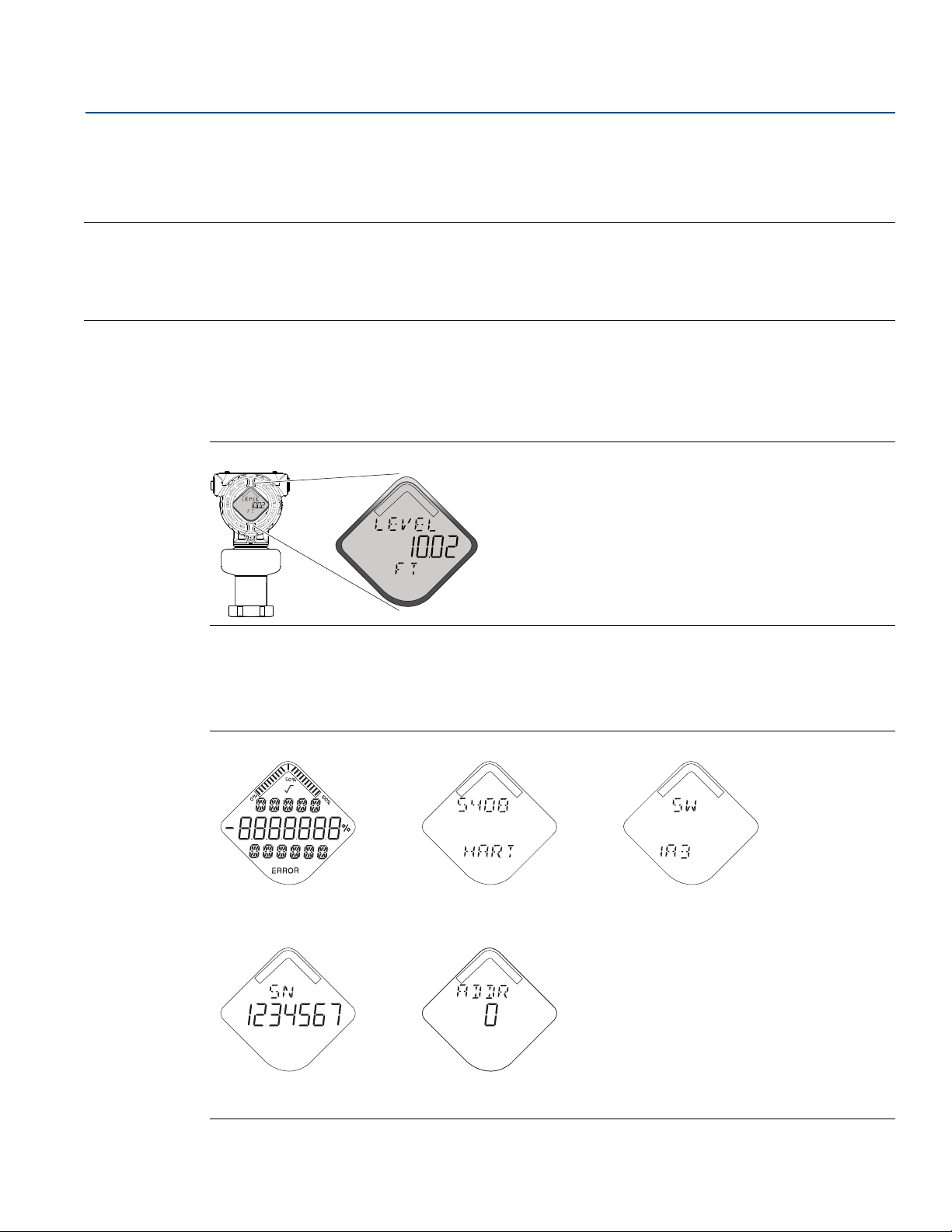
Reference Manual
00809-0100-4408, Rev BA
Section 6 Operation
LCD display screen messages . . . . . . . . . . . . . . . . . . . . . . . . . . . . . . . . . . . . . . . . . . . . . . . . . . . . . . . . . . page 75
Set up the LCD display . . . . . . . . . . . . . . . . . . . . . . . . . . . . . . . . . . . . . . . . . . . . . . . . . . . . . . . . . . . . . . . . page 76
View measurement data . . . . . . . . . . . . . . . . . . . . . . . . . . . . . . . . . . . . . . . . . . . . . . . . . . . . . . . . . . . . . . page 77
Check device status . . . . . . . . . . . . . . . . . . . . . . . . . . . . . . . . . . . . . . . . . . . . . . . . . . . . . . . . . . . . . . . . . . page 78
6.1 LCD display screen messages
The optional LCD display shows output variables and abbreviated diagnostic messages.
Figure 6-1. LCD Display (Option Code M5)
Operation
November 2017
6.1.1 Startup screen sequence
The following screens are shown on the LCD display when the transmitter is switched on:
Figure 6-2. Startup Screen Sequence
1. All segments on 2. Device type and
communication protocol
4. Serial number 5. Device HART® address
3. Software revision
Operation
75
Page 88

Operation
November 2017
6.1.2 Variable screens
The Rosemount™ 5408 and 5408:SIS Level Transmitters can display the following variables:
Table 6-1. LCD Display Variables
Reference Manual
00809-0100-4408, Rev BA
Parameter Presentation
Description
on display
Level LEVEL The current level measurement value.
Distance DIST Distance from the upper reference point to the product surface.
Level Rate LR
Signal Strength AMP The signal amplitude of the surface echo.
Vol ume VOLUM Volume of the product at the current level.
Electronics Temperature ITEMP The current temperature at the electronics.
Signal Quality
Scaled Variable
Percent of Range
Primary Variable
Auxiliary Percent of
Range
User Defined Variable
1. Only for transmitters ordered with Smart Diagnostics Suite (option code DA1).
2. Default, user selec table display text (up to f ive characters).
(1)
(1)
SIG
QUALITY
(2)
SCALE
PV
%RANGE
AUX
%RANGE
(1)
USER
(2)
The current velocity at which the level is moving. A positive value
indicates the surface is moving up.
The quality of product surface echo signal compared to surface
threshold and noise.
A variable calculated from a scaling table (as defined by pairs of
input/scaled values).
A variable value expressed in percent within a range defined by a
Lower Range Value (LRV) and an Upper Range Value (URV).
A variable value expressed in percent within a range defined by a
Lower Range Value (LRV) and an Upper Range Value (URV).
A variable associated with a selected register in the device. Refer
Table C-4 on page 200 for a list of suitable register variables.
6.2 Set up the LCD display
It is possible to specify the variables to be presented on the optional LCD display.
Rosemount Radar Master Plus
1. Under Configure, select Device Setup, and then select the Display tab.
2. Select the desired variables to be displayed on the LCD display.
3. Select Save.
AMS Device Manager and Field Communicator
1. Select Configure > Manual Setup > Device Setup > Display.
2. Select the desired variables to be displayed on the LCD display.
3. Select Send.
76
Operation
Page 89
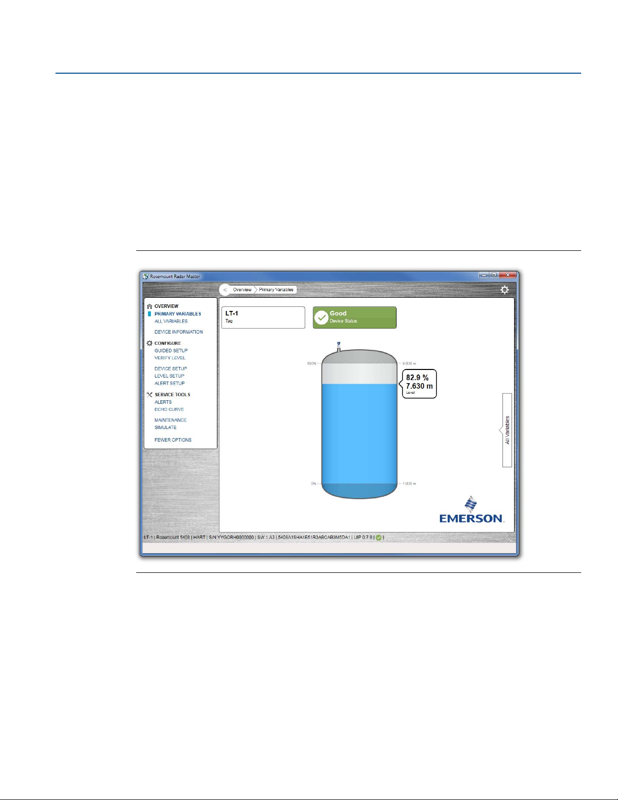
Reference Manual
00809-0100-4408, Rev BA
6.3 View measurement data
Measurement values can be viewed using Rosemount Radar Master Plus, AMS Device Manager, Field
Communicator, or other communicator.
6.3.1 View current measurement values
Rosemount Radar Master Plus
Current measurement data of the primary variables are presented on the Overview screen together with
a graphical representation of the tank (see Figure 6-3).
Select All Variables to view a complete list of all variables within the transmitter.
Figure 6-3. Rosemount Radar Master Plus - Overview Screen
Operation
November 2017
Operation
AMS Device Manager and Field Communicator
Current measurement data of the primary variables are presented on the Overview screen. To view all
current measurement values, do the following:
1. Select Service Tools > Variables.
2. Select Mapped Variable, Process, Device, or Signal Quality.
77
Page 90
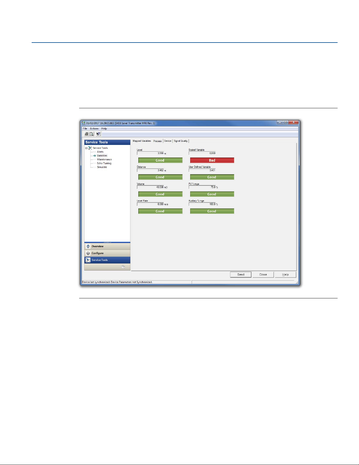
Operation
November 2017
6.3.2 Interpret measurement status
A “Good” or “Bad” status next to a value is an indication of the reliability or integrity of the data being
received, not an indication of whether or not the value is within the configured upper or lower ranges
(see Figure 6-4). A value that triggers an alert, such as a high or low temperature indication, will change
the overall status of the device, but the measurement might still be indicated as “Good” if the reliability
of the data is good.
Figure 6-4. AMS Device Manager - Status Indicators
Reference Manual
00809-0100-4408, Rev BA
6.4 Check device status
The overall device status is presented under the Overview screen in Rosemount Radar Master Plus, AMS
Device Manager, and Field Communicator. The transmitter reports diagnostic alerts when there is a
device malfunction. For information on these alerts, see “Diagnostic messages” on page 82.
The device can also be configured to report user defined alerts based on the measured variables, see
“Alert setup” on page 203 for more information.
To check device status and see whether there are any active alerts reported:
Go to the Overview screen to view the overall device status. If status is anything than Good, click the
button in the device status image to open a window with active alerts. The different device status
images are shown in Tab l e 6 -2 and Ta b le 6 - 3 .
OR
Select Service Tools > Alerts.
78
Operation
Page 91
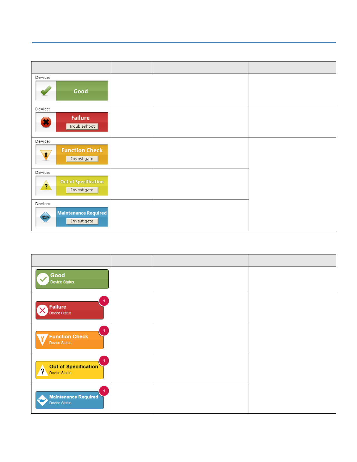
Reference Manual
00809-0100-4408, Rev BA
Table 6-2. Presentation of Device Status Images as per NAMUR NE 107 - AMS Device Manager
Device status image Category Description Action
Good No active alert. N/A
Failure At least one Failure alert is active. Click the Tro ub le sh oo t button to
open a window with active alerts
together with recommended
actions.
Operation
November 2017
Func tion
Check
Out of
Specification
Maintenance
Required
At least one Function Check alert is
active (and no Failure alerts).
At least one Out of Specification alert is
active (and no Failure or Function Check
alerts).
At least one Maintenance Required alert
is active (and no Failure, Function
Check, or Out of Specification alerts).
Click the Investigate button to
open a window with active alerts
together with recommended
actions.
Table 6-3. Presentation of Device Status Images as per NAMUR NE 107 - Rosemount Radar Master Plus
Device status image Category Description Action
Good No active alert. N/A
Failure At least one Failure alert is active.
Operation
Func tion
Check
Out of
Specification
Maintenance
Required
At least one Function Check alert is
active (and no Failure alerts).
At least one Out of Specification alert is
active (and no Failure or Function Check
alerts).
At least one Maintenance Required alert
is active (and no Failure, Function
Check, or Out of Specification alerts).
Click the device status image to
open a window with active alerts
together with recommended
actions.
79
Page 92

Operation
November 2017
Reference Manual
00809-0100-4408, Rev BA
80
Operation
Page 93

Reference Manual
Service and Troubleshooting
00809-0100-4408, Rev BA
Section 7 Service and Troubleshooting
Safety messages . . . . . . . . . . . . . . . . . . . . . . . . . . . . . . . . . . . . . . . . . . . . . . . . . . . . . . . . . . . . . . . . . . . . . page 81
Diagnostic messages . . . . . . . . . . . . . . . . . . . . . . . . . . . . . . . . . . . . . . . . . . . . . . . . . . . . . . . . . . . . . . . . . page 82
Troubleshooting guide . . . . . . . . . . . . . . . . . . . . . . . . . . . . . . . . . . . . . . . . . . . . . . . . . . . . . . . . . . . . . . . page 87
Service and troubleshooting tools . . . . . . . . . . . . . . . . . . . . . . . . . . . . . . . . . . . . . . . . . . . . . . . . . . . . . page 92
Write protect a transmitter . . . . . . . . . . . . . . . . . . . . . . . . . . . . . . . . . . . . . . . . . . . . . . . . . . . . . . . . . . page 105
Application challenges . . . . . . . . . . . . . . . . . . . . . . . . . . . . . . . . . . . . . . . . . . . . . . . . . . . . . . . . . . . . . . page 106
Transmitter head replacement . . . . . . . . . . . . . . . . . . . . . . . . . . . . . . . . . . . . . . . . . . . . . . . . . . . . . . . page 112
Cleaning or replacing the PTFE sealing . . . . . . . . . . . . . . . . . . . . . . . . . . . . . . . . . . . . . . . . . . . . . . . . . page 115
Service support . . . . . . . . . . . . . . . . . . . . . . . . . . . . . . . . . . . . . . . . . . . . . . . . . . . . . . . . . . . . . . . . . . . . . page 119
7.1 Safety messages
November 2017
Procedures and instructions in this section may require special precautions to ensure the safety of the
personnel performing the operation. Information that raises potential safety issues is indicated by a
warning symbol ( ). Refer to the following safety messages before performing an operation preceded
by this symbol.
Failure to follow safe installation and service guidelines could result in death or serious injury.
Make sure only qualified personnel perform the installation.
Explosions could result in death or serious injury.
Verify that the operating environment of the transmitter is consistent with the appropriate
hazardous locations certifications.
Before connecting a Field Communicator in an explosive atmosphere, make sure the instruments in
the loop are installed in accordance with intrinsically safe or non-incendive field wiring practices.
Do not remove the transmitter covers in explosive atmospheres when the circuit is alive.
Both transmitter covers must be fully engaged to meet explosion-proof requirements.
Process leaks could result in death or serious injury.
Make sure that the transmitter is handled carefully. If the process seal is damaged, gas might escape
from the tank.
Electrical shock can result in death or serious injury.
Avoid contact with the leads and terminals. High voltage that may be present on leads can cause
electrical shock.
Make sure the main power to the transmitter is off and the lines to any other external power source
are disconnected or not powered while wiring the transmitter.
Service and Troubleshooting
81
Page 94

Service and Troubleshooting
November 2017
7.2 Diagnostic messages
Diagnostic messages per NAMUR NE 107 are listed in Tab l e 7- 1 to Ta b le 7 - 5 .
Table 7-1. Status - Failed
Reference Manual
00809-0100-4408, Rev BA
LCD display
message
ELEC
FAI LUR
ELEC
FAI LUR
MEMRY
FAI LUR
SIGNL
FAI LUR
START
FAI LUR
SW
ERROR
MEAS
FAI LUR
Host diagnostic
Description Recommended actions
message
Electronics Failure,
Tr an sm i tt er
Electronics Failure, Sensor
Module
Device Memory Failure A device memory error has occurred.
Radar Signal Failure The received radar signal is invalid
Startup Failure Device repeatedly failed to start up with
Software Error The software in the device encountered a
Level Measurement Lost No valid level reading. Reasons may be
An electronics error has occurred.
The device measurement reading is
invalid.
An electronics error has occurred.
The device measurement reading is
invalid.
The device measurement reading is
invalid.
resulting in an invalid device
measurement reading.
user configuration settings.
The device measurement reading is
invalid.
problem and stopped running which may
cause an invalid measurement reading.
In some cases, problems may be caused
by temporary environmental conditions
(e.g. electromagnetic interferences) and
not observed again.
multiple:
No valid surface echo peak in the
measuring range.
Incorrect device configuration.
1. Restart the device.
2. If the condition persists, replace the
device.
1. Restart the device.
2. If the condition persists, replace the
device.
1. Restore default settings, restart device,
and reconfigure the device.
2. If the condition persists, replace the
device.
1. Clean the antenna.
2. If the condition persists, replace the
device.
1. Check supply voltage is within range
and restart device.
2. Restore default settings, restart device,
and reconfigure the device.
3. If the condition persists, replace the
device.
1. Restart the device.
2. Restore default settings and
reconfigure the device.
3. If the condition persists, replace the
device.
1. Analyze the Echo Curve at time of loss
for reason and check device
configuration, especially thresholds.
2. Check device physical installation (for
instance antenna contamination).
3. Consider increasing Measurement
Recovery Time parameter for
intermittent conditions.
4. Restart the device.
5. Restore default settings and
reconfigure the device.
6. If the condition persists, replace the
device.
82
Service and Troubleshooting
Page 95

Reference Manual
00809-0100-4408, Rev BA
Service and Troubleshooting
November 2017
LCD display
message
CONFG
ERROR
Host diagnostic
Description Recommended actions
message
Configuration Error The device has detected a configuration
error. Reasons may be multiple (see
Ta bl e 7 - 2 for details).
1. Click the Details button for more
information.
2. Correct the parameter causing the
error.
Table 7-2. Configuration Error Details
Host diagnostic message Description Recommended actions
Volume Configuration Error The volume cannot be calculated correctly
with the current configuration.
Scaled Variable Configuration
Error
Geometry Configuration Error The configured tank geometry results in a
Primary Variable Configuration
Error
The Scaled Variable configuration is
incorrect.
too large level measuring range for this
device.
The Primary Variable selection is not
supported.
Note
Rosemount™ 5408:SIS only supports level
or distance as Primary Variable.
1. If strapping table is used, check that level-volume
values are entered in increasing order.
2. If strapping table is used, check that number of
strapping points to use is correct.
3. If tank dimensions are used for volume, check
that geometry shape and size measures are
correct.
4. If condition persists, restore default settings and
reconfigure the device.
1. Check that the value pairs in the scaled variable
table are entered in increasing order.
2. Check the number of table points to use is
correct.
3. If condition persists, restore default settings, and
reconfigure the device.
1. Check tank geometry configuration and reduce
Reference Height.
2. If condition persists, restore default settings and
reconfigure the device.
1. Change Primary Variable to variable supported by
device.
2. Consider purchasing an upgrade of the device to
access additional variables.
Measurement Correction
Configuration Error
Threshold Configuration Error The surface threshold configuration is
Service and Troubleshooting
The factory measurement correction data
is invalid.
incorrect.
1. Restore default settings and reconfigure the
device.
2. If the condition persists, replace the device.
1. In the threshold table, check that
distance-threshold values are entered in
increasing order.
2. Check that the number of threshold points to use
is correct.
3. If condition persists, restore default settings and
reconfigure the device.
83
Page 96

Service and Troubleshooting
November 2017
Host diagnostic message Description Recommended actions
Reference Manual
00809-0100-4408, Rev BA
Factory Approval Error The Sensor Module factory approval is
missing.
The Transmitter factory approval is
missing.
SIS Configuration Error It is currently not possible to enable Safety
Mode due to other active alerts.
Note
Rosemount 5408:SIS only supports liquids
level measurement when operating in
Safety (SIS) mode.
Function Not Supported Functionality in the device is enabled, but
not supported by this device.
Additional features may be enabled by
purchasing an upgrade of the device.
Antenna Type Configuration
Error
Factory Calibration Error The factory calibration in the device is
Analog Out Span Configuration
Error
Analog Out Calibration Error Analog output calibration failed.
SIS Multidrop Error HART® multidrop mode is not supported
Engineering Unit Configuration
Error
The configured Antenna Type is not
supported by the device.
missing.
The span for the configured analog out
range is too small.
for safety (SIS) devices. Only 4-20 mA
output is supported for safety devices.
One of the configured engineering units is
not supported by the device.
1. Restart the device.
2. Restore default settings and reconfigure device.
3. If the condition persists, replace the device.
1. Clear other active alerts by priority order until this
alert is cleared.
2. Change Operational Mode to Control/Monitoring
if device is not intended to be used as safety
device.
3. If the condition persists, restore default settings
and reconfigure device.
1. Check that selections for variables (e.g. Primary
Variable) are supported by this device.
2. Turn off functionality not supported by this
device.
3. Consider purchasing an upgrade of the device to
access additional variables and functionality.
4. If condition persists, restore default settings and
reconfigure device.
1. Check configuration of Antenna Type.
2. Make sure the configured antenna type matches
the physical antenna for the device.
1. Replace the device.
1. Increase analog out span by adjusting Upper or
Lower Range Value.
1. Try calibrating the analog output again.
2. If the condition persists, replace the device.
1. Disable multidrop mode.
2. Change Operational Mode to Control/Monitoring
if device is not intended to be used as safety
device.
3. If the condition persists, restore default settings
and reconfigure device.
1. Check unit configuration.
2. If condition persists, restore default settings and
reconfigure device.
84
Service and Troubleshooting
Page 97

Reference Manual
Service and Troubleshooting
00809-0100-4408, Rev BA
Host diagnostic message Description Recommended actions
November 2017
Burst Mode Configuration Error The burst mode configuration is incorrect.
Start Code Configuration Error The start code to enable options in the
device is invalid.
Note
Start codes are unique for individual
devices and cannot be copied from one
device to another.
Table 7-3. Status - Function Check
LCD display
message
SAFE
DISBLD
SIMUL
ACTIVE
Host diagnostic
Description Recommended actions
message
Safety Mode Not
Activated
Simulation/Test Active The device is in simulation or test mode
Safety Mode is disabled and device is in
alarm mode.
This device is configured for use in Safety
Instrumented Systems (SIS) which
requires Safety Mode to be enabled.
and is not reporting actual information.
1. Check configuration of burst mode.
2. If condition persists, restore default settings and
reconfigure device.
1. Enter a valid start code for this device using the
Upgrade function.
2. If condition persists, contact your local Emerson
representative to get a valid start code.
1. Change Safety Mode to Enabled for use
in SIS application.
2. Change Operational Mode to
Control/Monitoring if device is not
intended to be used as safety device.
1. If this behavior is not desired, stop
simulation or test mode.
2. If the condition persists, restart device.
™
Table 7-4. Status - Out of Specification
LCD display
message
TEMP
LIMITS
Host diagnostic
message
Electronics Temperature
Out of Limits
Table 7-5. Status - Maintenance Required
LCD display
message
SUPLY
LOW
LOW
SIG Q
Host diagnostic
message
Supply Voltage Low The supply voltage is low and may affect
Low Signal Quality The Signal Quality is below the defined
Description Recommended actions
The temperature of the electronics board
has exceeded the transmitter’s operating
range.
1. Verify ambient temperature is within
the operating range.
2. Remote mount the transmitter away
from the process and environmental
conditions.
Description Recommended actions
1. Check supply voltage is within range.
device operation.
1. Take ac tion based on your intended use
alert limit.
of this alert.
2. Clean the antenna.
3. If no actions were necessary, consider
to change the limit.
Service and Troubleshooting
85
Page 98

Service and Troubleshooting
November 2017
Reference Manual
00809-0100-4408, Rev BA
LCD display
message
HIGH
ALERT
LOW
ALERT
VAR
OUTRNG
DC
DEGRAD
Host diagnostic
Description Recommended actions
message
High User Defined Alert The user defined variable is above the
defined limit.
Low User Defined Alert The user defined variable is below the
defined limit.
Linearized Variable Out of
Range
Dielectric Constant
Estimation Degraded
The level measurement is outside the
configured range for volume or scaled
variable, or both.
Accuracy of volume/scaled variable
measurement may be degraded.
The dielectric constant estimation is
degraded.
Accuracy of level measurement may be
degraded.
1. Bring the system to a safe state.
2. Verify that the process variable is within
specified limits.
3. Reconfirm the user defined alarm limit.
4. If not needed, disable this alert.
1. Bring the system to a safe state.
2. Verify that the process variable is within
specified limits.
3. Reconfirm the user defined alarm limit.
4. If not needed, disable this alert.
1. If volume strapping table is used, make
sure level values within operating
range are included.
2. If scaled variable table is used, make
sure input variable values within
operating range are included.
1. Check configuration of Bottom Product
Dielectric Constant.
2. Check configuration of Reference
Height and Bottom Offset.
3. If not needed, disable Tank Bottom
Projection.
86
Service and Troubleshooting
Page 99
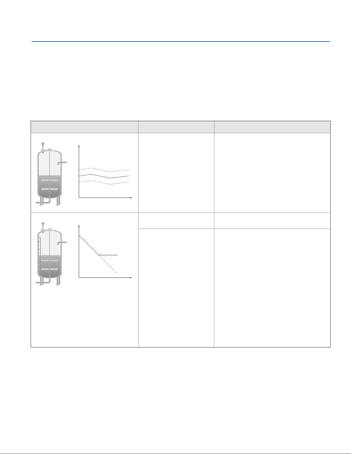
Reference Manual
Level
Time
Level
Time
00809-0100-4408, Rev BA
7.3 Troubleshooting guide
If there is a malfunction despite the absence of alerts, see Ta b l e 7- 6 and Ta bl e 7 - 7 for information on
possible causes and recommended actions.
The troubleshooting guide contains the following symptoms:
Incorrect level readings (see Tab l e 7 -6 )
Troubleshooting the 4-20 mA/HART output (see Ta b le 7 - 7 )
Table 7-6. Incorrect Level Readings
Service and Troubleshooting
November 2017
Symptom
(1)
Possible causes Recommended actions
Reported level is too high or low. Incorrect tank geometry
configuration.
Level is stuck in measuring range. Incorrect alignment of the
transmitter.
Disturbing objects in the tank.
Verify the tank geometry parameters are
configured correctly (especially the Reference
Height).
Run Verify Level to adjust level measurement,
see “Verify Level” on page 72.
Analyze the echo curve and check amplitude
thresholds, see “Set amplitude thresholds” on
page 96.
Restore default settings and reconfigure the
device.
Verify the transmitter head is correctly aligned,
see “Align transmitter head” on page 37.
Use the suppress false echoes function to
manage strong disturbance echoes, see
“Suppress false echoes” on page 97.
Analyze the echo curve and check amplitude
thresholds, see “Set amplitude thresholds” on
page 96.
Remove the disturbing object.
Change alignment of transmitter head in steps of
about 15 degrees, see “Align transmitter head”
on page 37. After each step, check if impact of
disturbing echoes is decreased using the echo
curve.
Put an inclined metal plate on top of the
disturbing object.
Move the transmitter to another position. Refer
to Section 3: Mechanical Installation for
installation considerations.
Service and Troubleshooting
87
Page 100
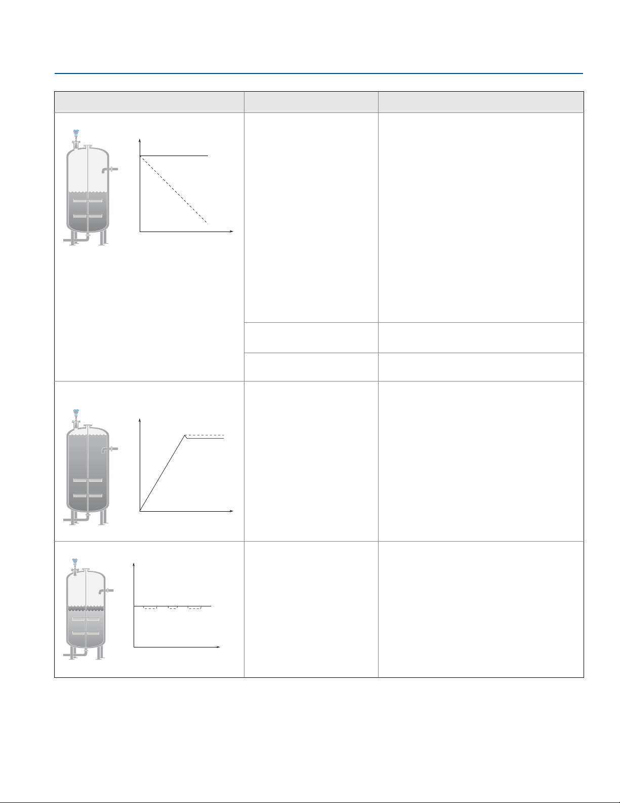
Service and Troubleshooting
Level
Time
Level
Time
November 2017
Reference Manual
00809-0100-4408, Rev BA
Symptom
(1)
Possible causes Recommended actions
Level is stuck in full tank. Disturbing objects near the
antenna.
Level
Time
Product build-up on the
antenna.
Cone antenna does not extend
below the nozzle.
Level value drops to a lower value when
product surface is close to antenna.
Product surface is within the
Upper Null Zone and a
disturbance echo is
interpreted as the product
surface.
Use the suppress false echoes function to
manage strong disturbance echoes, see
“Suppress false echoes” on page 97.
Analyze the echo curve and check amplitude
thresholds, see “Set amplitude thresholds” on
page 96.
For process seal antenna installed in a nozzle
taller than 10-in. (25 cm), adjust the
pre-configured amplitude threshold, see
“Handling disturbances at top of tank” on
page 106.
Increase the Upper Null Zone, see “Handling
disturbances at top of tank” on page 106.
Remove the disturbing object.
Move the transmitter to another position. Refer
to Section 3: Mechanical Installation for
installation considerations.
Clean the antenna.
Use transmitter with air purging connection.
Use the extended cone antenna.
Check the setting of the Upper Null Zone, see
“Upper null zone” on page 199.
Measured value jumps to a lower value. Multiple products in the tank,
e.g. thin oil layer on top of
water that is sometimes
detected, sometimes not.
88
Set Double Surface Handling to Track Upper
Surface or Track Lower Surface, see “Double
surface handling” on page 201.
Service and Troubleshooting
 Loading...