

Emerson Sempell S Series, Sempell SO, Sempell SB, Sempell SC, Sempell SOH Operating Instructions Manual
SEMPELL SERIES S, TYPES SO, SC, SB, SOH FULL-LIFT SAFETY VALVES
OPERATING INSTRUCTIONS
Before installation these instructions must be fully read and understood
ATTENTION
This operating instruction does not specify the
extent of delivery. It is valid for several sizes,
designs, accessories and additional devices.
It contents generally exceeds the contractual
determined extent of delivery.
1 DANGER AND WARNING INDICATIONS
The construction of the Sempell safety valves
of the series S corresponds to the standard
technology and the valid safety regulations.
Nevertheless, improper use or improper
installation can cause risks for the personnel
or can lead to restrictions in regard of the
operational safety. Therefore, the Sempell
GmbH recommends the operator of the safety
valves to take appropriate measures and make
sure that the present operating instructions
are read and understood by the assigned
personnel.
Type
Series S, types SO, SC, SB, SOH full-lift
safetyvalves
Orifice letter D - Z
Design
• Spring-loaded
• With DIN and ANSI connections
• According to API Standard 526
• According to AD A2, TRD 421
For the application of a pneumatic drive A160
see corresponding operating instruction
VCIOM-02239.
Observe design data on the nameplate!
APPLICATION LIMITS
It is only allowed to use the valves according to the
details of this operating instruction and according
to the parameters and application cases agreed
in the delivery contract (see nameplate). The
application of the valve has to take place adequate
to the medium tolerances of the used materials.
WARNINGS FOR THE OPERATING AND
MAINTENANCE PERSONNEL
Before commissioning and maintenance works
familiarise yourself with the legal accident
prevention regulations, the local safety
instructions and this operating instruction and
observe them.
Use the safety valve and its individual parts and
accessories only for the purpose intended byus.
Emerson.com/FinalControl © 2017 Emerson. All rights reserved.
MA.280.01.1215 E
VCIOM-02373-EN 16/07

SEMPELL SERIES S, TYPES SO, SC, SB, SOH FULL-LIFT SAFETY VALVES
OPERATING INSTRUCTIONS
Please observe the following points besides
the notes given in the text
• Danger of burning at safety valves and with
their connected lines while operating under
increased temperature.
• Disassembly of the safety valve only in case of
pressureless plant or after cooling down.
• Protection against risks caused by
evaporation also in case of pressureless
system; for information please contact the
safety inspector concerned.
• After assembly check all sealing points in
regard of tightness.
• In case of adjustment make changes at
pressure screw and adjusting ring only with
sunstantially reduced pressure to avoid
unintended response.
• Carry ear protection during adjustment,
ifnecessary.
• Danger of burning by discharge of small
amounts of possibly hot medium in case
of safety valves with open spring bonnet
(typeSO).
• Danger of injury while discharging in case of
disconnected discharge line.
• Extreme vibrations can lead to inadmissible
increase of operating pressure with the
possibly destruction of the safety valve or to
the destruction of the balanced bellows with
unintentional escape of medium.
• In case the valve is provided with a steam
jacket or a steam flushing device, the
corresponding design must be considered
while connecting.
Plant downtimes
NOTICE
For longer system downtimes, a downtime
preservation must be carried out.
If systems are set out of operation for a shorter
or longer time, procedures (VGB - R 116)
depending on downtime duration and frequency
should be applied to preserve the system.
Limitation of liability
All specifications and notices in this instruction
manual were drawn up with consideration of
the applicable standards and regulations, the
status of technology and our longstanding
findings and experiences.
The manufacturer does not assume liability for
damages in the following cases:
• Non-adherence to this instruction manual
• Usage deviating from the intended use
• Employment of untrained personnel
• Independent reconstruction
• Technical modifications
• Usage of unauthorized spare parts
• Use of unauthorized operating media
• Improper maintenance and setting of
thevalve
• Temporary or permanent connection of
devices not authorized by us
The actual scope of delivery may deviate from
the explanations and figures described here
regarding special versions, the utilization
of additional order options or due to newest
technical modifications.
The obligations, General Business Terms and
Conditions and the delivery conditions of the
manufacturer agreed upon in the delivery
contract are applicable, along with the legal
regulations valid at the time of contract
conclusion.
2 DESCRIPTION
Spring-loaded safety valves are direct acting
safety valves with which pressure vessels
are protected against inadmissible excess
pressure.
A cylindrical compression spring creates the
closing force on the valve disc against the
opening pressure of the medium below the
valve disc. Under normal operating conditions
the valve seat is kept tight.
By changing the spring compression the
set pressure can be changed. When the set
pressure is surpassed, the pressure of the
medium prevails and the safety valve opens.
In case of full-lift characteristic the safety valve
opens abruptly over the full lift and discharges
the whole mass flow which is necessary to
prevent further increase of the pressure.
The safety valve closes again after a defined
pressure reduction.
Please observe the planning manual for the
precise design of the safety valves.
For the application of this operating instruction
please take the exact type name (e.g. SC, SB)
from the nameplate of your valve.
Use within areas exposed to danger of
explosion:
The safety valves underwent a hazard analysis
according to code 94/9/EC with the following
result:
• The safety valves do not have a potential
ignition source. ATEX 94/9/EC is not
applicable to these valves.
• The valves safety may be used in the EX area
• Electrical / pneumatically accessories have to
undergo a separate assessment of conformity
according to ATEX.
• The surface temperature does not depend
from the valve itself but from the operational
conditions. Observe while installing.
2

SEMPELL SERIES S, TYPES SO, SC, SB, SOH FULL-LIFT SAFETY VALVES
OPERATING INSTRUCTIONS
3 OPERATION
3.1 Warning indications for the operation
Observe safety regulations!
ATTENTION
Unstable behaviour of safety valves such as
chattering or vibrating can destroy the valve seat,
the safety valve or the line and thus causing the
failure of the safety function or the shutdown of
the plant.
Therefore, observe regulations and empirical
notes regarding design and dimensioning, fitting
and installation.
• Design and dimensioning: do not use larger
safety valves than necessary! In case of back
pressure use safety valves with bellows.
• Fitting and installation: design supply line
as short as possible. Use as few bends as
possible.
• Keep supply line free from vibrations. Absorb
or avoid pressure surges and waves, e. g.
caused by pumps or other valves.
• Drain the discharge line and the valve body at
their lowest point. Condensate can impair the
function of the safety valve.
• Protect lines and valve against freezing.
3.2 Storage rules
To preclude damages during loading and
unloading move the valves cautiously.
At delivery the outsides of all ferritic parts of
the safety valve are supplied with a coat of paint
except the welding edges and gasket surfaces.
The insides are protected by a watery corrosion
preservative that has a long-term effect
because of the film formative active agents.
All connection inlets are closed by
corresponding caps.
In this state the safety valve can be stored in
closed, dust-free and dry rooms lying on a
pallet without difficulties. Time of storage about
six months.
Storage of more than six months asks for a
disassembly and a visual check of the inner
parts of the safety valves. A weather-protected
outside storage is not allowed.
For spare parts out of elastic material
(O-rings, scraper rings, rod and piston
gaskets) additionally apply:
Moisture
To prevent the formation of condensate, avoid
moist storerooms. A relative humidity of
below65% is at best.
Lighting
The products of elastic materials are to protect
from direct sun light and from strong artificial
light with a high ultraviolet part. Therefore
supply the windows of the storerooms with a
red or orange (in no case blue) paint.
Ozone
Protect products of elastic materials from
ozone (formation of cracks and embrittlement).
The storeroom may not contain ozone
generating systems (fluorescing sources
of light, mercury vapour lamps, electric
motors,etc.).
Oxygen
Protect products out of elastic materials from
draught by storage in airtight boxes. Oxygen
causes cracking and embrittlement.
If these requirements are guaranteed for
products out of elastic materials the storage
time is about 5 years.
For spare parts out of steel
Store the parts in closed, dust-free and dry
rooms so that damages do not occur.
Especially the following protection measures
have to take place:
Disc (3): wax coat of the gasket, net coat
Disc holder (7): protection by net coat
3.3 Transport instructions
The welding ends or flanges are protected by
plastic caps.
The coating is a primer which is designed to
provide protection against corrosion during
transport and storage. Do not damage the layer
of coating.
Transport is only permitted on original
manufacturer’s transport items (e.g. pallets).
WARNING
Material damage due to improper transport!
If not transported properly, transport items can
fall or crash. This can result in significant material
and personal damage.
Temperature
The temperature of the storage shall be
between 0°C and 25°C since otherwise a
hardening of the material and so a shortening
of durability will follow. Shield heating elements
and lines in heated storeroom so that no direct
heat irradiation arises. The distance between
the heat source and the stocks has to be 1 m
at least.
3
SEMPELL SERIES S, TYPES SO, SC, SB, SOH FULL-LIFT SAFETY VALVES
OPERATING INSTRUCTIONS
• Proceed with caution and observe the
information on the packaging when unloading
the transport items on delivery and when
transporting internally.
• Protect the valve against bumps and blows
during transport.
• Use the attachment points provided.
• Only remove packaging just before assembly.
To preclude damages during transport move
valves by hand or with suitable lifting gears.
It is not permitted in any case to lift or transport
the valve by means of the lifting lever.
Actuator elements are not suitable as
attachment points. If the use of a lifting device
is necessary, it is preferable to wind a round
sling around the valve body and upper part in
order to transport the valve in a vertical position
to its destination.
3.4 Installation instructions
NOTE
Clean lines before installing safety valves as otherwise
the valve seats can be damaged by foreign particles
when discharging!
• Remove plastic caps protection just before
installation.
• Check plant identification and details on the
nameplate.
• Vertical installation position, inlet from
below. Prevent bracing of the valve body by
connected line.
3.5 Connection of lines
3.5.1 Inlet line
If possible arrange safety valve directly at the
nozzle of the tank to be protected. Otherwise
lay inlet line between tapping point and safety
valve as short and as low in resistance as
possible.
In no case the inlet line diameter shall be
smaller than the inlet nominal size of the
safetyvalve.
The pressure loss in the inlet line must not
exceed 3% of the set pressure at the highest
possible discharge quantity.
Check inlet line in regard of pressure vibrations
according to FBR 153 as far as possible.
ATTENTION
A pressure loss higher than the closing pressure
difference may lead to an unstable, uncontrollable
behaviour of the safety valve; chattering or
vibrating may destroy the valve seat, the safety
valve or the line and thus lead to the failure of the
safety function or to the shutdown of the plant!
In order to facilitate the drainage of
condensate, the inlet line must be mounted to
the valve with at least a 15-degree ascending
slope position.
ATTENTION
Condensate at the inlet of the safety valve
changes the functional behaviour and may lead
to an inadmissible pressure increase. Danger of
explosion!
X
Y
PLEASE NOTE
Stresses at the valve body may lead to leaking at
the valve seat!
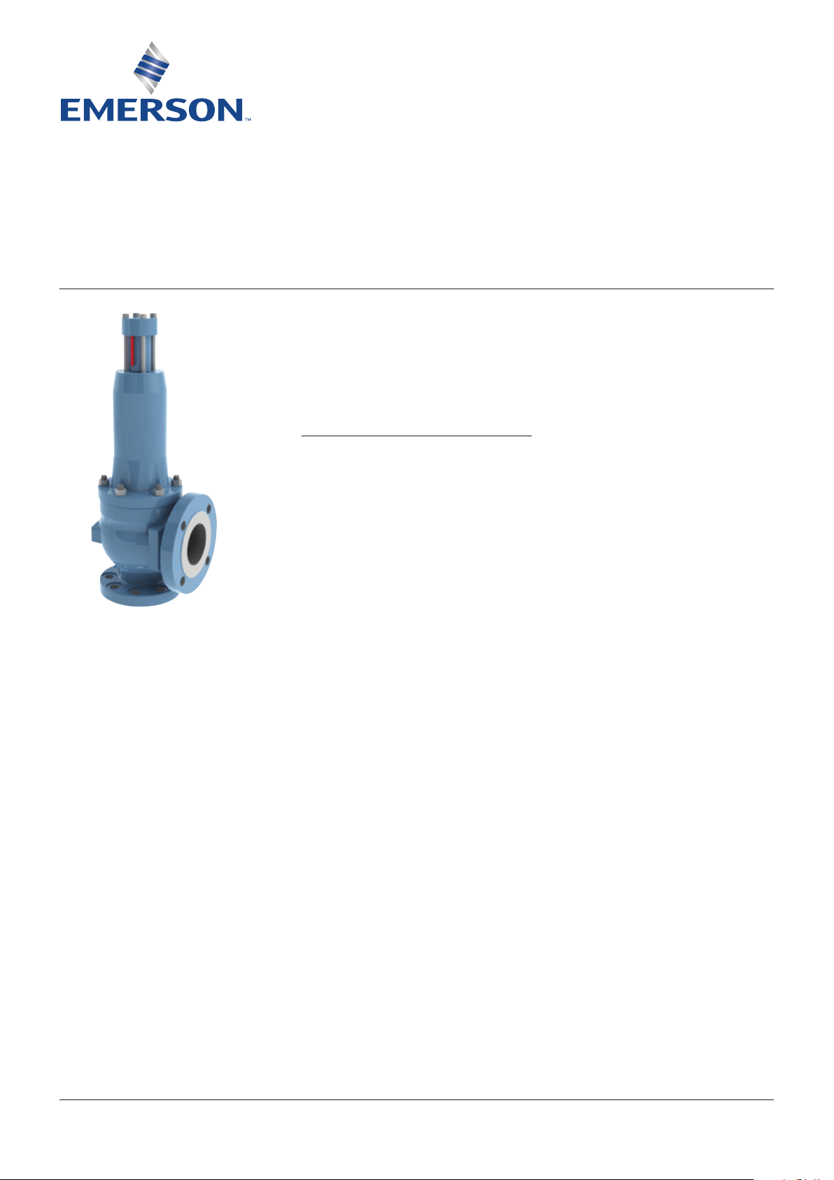
The installation point must be easily accessible
so that necessary maintenance works can be
carried out. The free space above the valve
should at least correspond to the dimensionX
(see table). In case of major valves (over 4”)
additional space should be provided for lifting
gears, at least 500 mm.
In case of hot medium, e. g. steam, insulate
supply line and valve body. The spring bonnet
must remain free. Without insulation the
produced condensate may cause malfunction.
Orifice letter Overhead dimension X (mm)
D - J 300
K - R 700
T 900
T1 1000
U - Z 1200
Y = Upper edge insulation
In case of liquids with temperatures higher than
the ambient temperature, the inlet line must
be assembled with slope to the safety valve, or
designed as a siphon-type bend in front of the
safety valve. Thereby, a heat transmission to
the safety valve is avoided which could impair
the tightness at the valve seat.
4

SEMPELL SERIES S, TYPES SO, SC, SB, SOH FULL-LIFT SAFETY VALVES
OPERATING INSTRUCTIONS
ADMISSIBLE BACK PRESSURES
Valve type Medium Maximum back pressure
SO.. Gases/vapours Superimposed back pressure constant 0% p
Superimposed back pressure variable 0% p
Built-up back pressure 15% p
SC.. Gases/vapours Superimposed back pressure constant 50% p
Superimposed back pressure variable 0% p
Built-up back pressure 15% p
Liquid Superimposed back pressure constant 80% p
Superimposed back pressure variable 0% p
Built-up back pressure 15% p
SB.. Gases/vapours Superimposed back pressure constant 50% p
Superimposed back pressure variable 50% p
Built-up back pressure 50% p
Liquid Superimposed back pressure constant 50% p
Superimposed back pressure variable 50% p
Built-up back pressure 50% p
3.5.2 Exhaust line
In no case the exhaust line diameter must be
smaller than the outlet nominal size of the
safety valve.
For valves type SO and SC back pressures
up to 15% of the set pressure and for valves
with bellows of type SB and valves with
compensating piston (SN 144) back pressures
up to 50% are acceptable unless there are
other restrictions such as mechanical loading
capacity of the bellows or insufficient strength
of the body connection flange.
ATTENTION
Higher back pressures may lead to an unstable,
uncontrollable behaviour of the safety valve;
chattering or vibrating may destroy the valve seat,
the safety valve or the line and thus lead to failure
of the safety function or to shutdown of the plant!
ATTENTION
An icy, frozen or clogged exhaust line leads to the
failure of the safety function! Dangerof explosion
in case of excess-pressure!
At the deepest point the exhaust line must be
equipped with a drain large enough to enable
the discharge of minor leaks, e. g. in case of
untight valve seat. Particularly in the open air
exhaust line, valve body and drain must be
protected against icing and freezing, e.g. by
(electrical) trace heating; merely insulating is
not sufficient!
CAUTION
In case of several safety valves with one common
exhaust line, take special safety precautions for
disassembling of only one safety valve to exclude
danger in case of unintended discharge of other
safety valves!
Recommendation! Sound isolate exhaust line
and/or provide the same with silencer; in doing
so, regard allowable back pressure!
3.6 Pressure test of installation
The response of the safety valve must be
prevented.
Either flange off the safety valve and close
the supply line with a blind flange or block
the valve. In case of welded-in safety valve a
pressure test insert can be used.
ATTENTION
In case of a blocked safety valve the test pressure
can amount up to 1.5 × of the set pressure without
consultation with Sempell.
5
35
U - Z
21.1
20
U - Z
21.1
20
SEMPELL SERIES S, TYPES SO, SC, SB, SOH FULL-LIFT SAFETY VALVES
OPERATING INSTRUCTIONS
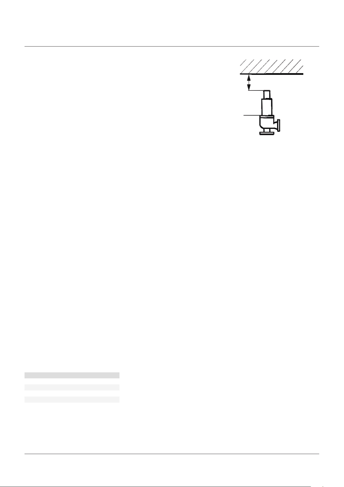
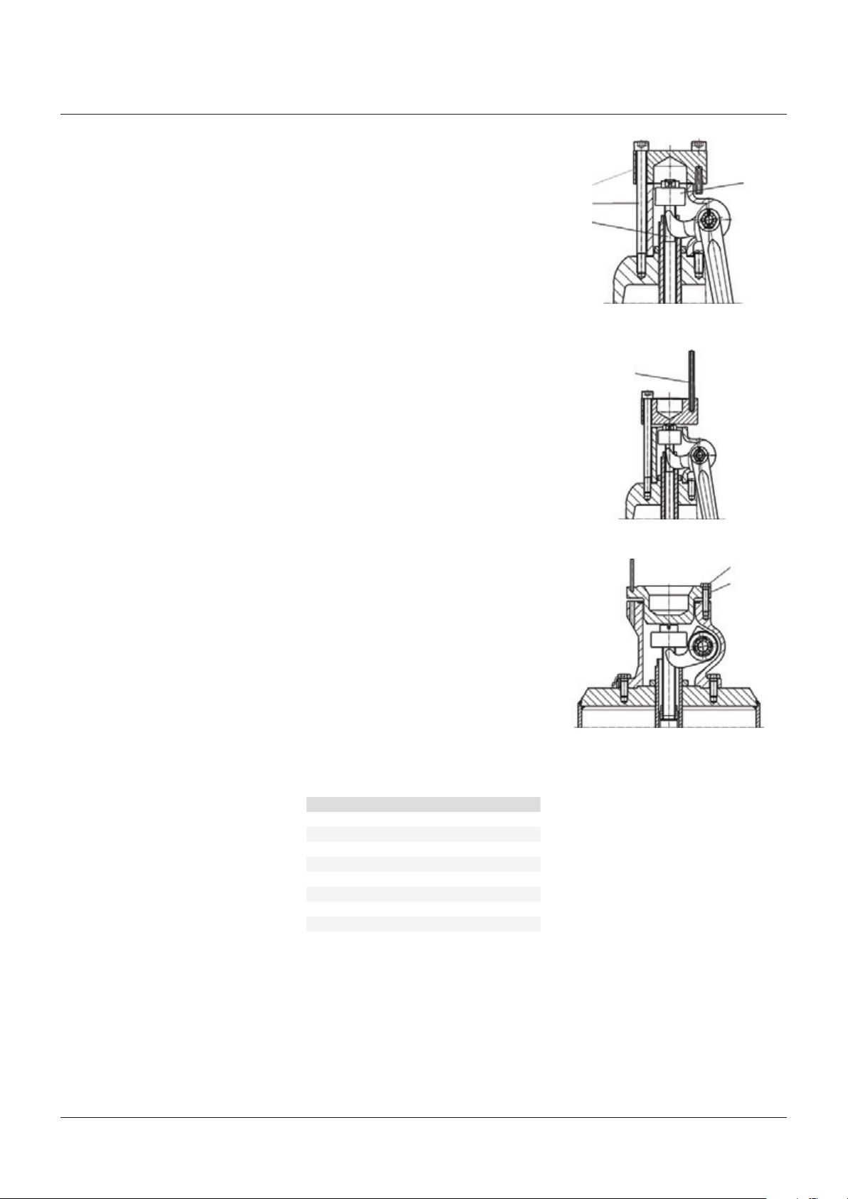
For orifice D to T1 loosen the 4 cap bolts
(21) and for orifice U to Z the four hexagonal
screws (21.1). Remove the cap top (20) and put
it reversed on place again. Now it rests on the
spindle end (11) and will be retightened again.
Now the valve is blocked. The signal pin (35)
or the blocking screw fixed in the cap top (20)
points upward and so shows the blocked state.
ATTENTION
After the pressure test restore and control the
ready-to-operate state.
3.7 Commissioning
The blocking screw must be removed for all
valves delivered in the blocked position.
The safety valve is ready for operation.
Theset pressure is adjusted and lead sealed
to prevent unauthorized adjustment. Higher
medium temperatures can lower the response
point by about 1% per 100 °C and require a
readjustment under operating conditions.
Please take standard values from the table in
section 3.9, “Adjustment of the set pressure”.
3.8 Operational test, discharge test
The function and reliability of the safety
valves, type S, have been proved by a type test
conducted by the US National Board of Boiler
and Pressure Vessels Inspectors as well as
by a component test according to VdTÜV 966.
Therefore, an operational test in the plant
need not be conducted and is restricted to
exceptions, normally at the time of revision of
steam boiler safety valves.
Before discharge test, apply ear plugs.
Slowly increase the operating pressure in the
plant until the safety valve is fully opened.
Lower the operating pressure until the safety
valve closes.
In case of several discharge tests with hot
steam allow intermediate cooling down of the
safety valve as, caused by the heating of the
spring, a slight decrease of the set pressure is
possible.
ATTENTION
In case of safety valves, type SO.. (with open valve
bonnet) some leaking medium may pass out
at the bonnet (12) when discharging. Danger of
scalding by steam!
3.9 Adjusting the set pressure
ATTENTION
A change of the lead sealed spring adjustment
must only take place in the presence of the
competent inspector.
The adjustment of the set pressure takes place
on the test stand. It shall be adjusted in the
plant only if there is no other possibility.
In any case the adjustment in the plant should
be applied with the pneumatic measuring
device A143 as by means of this device the set
pressure can be adjusted without increasing
the operating pressure (see Technische Schrift
KW 271: Sesi-Test, “Mobile Device A 143 for the
Test of Spring-loaded Safety Valves”.)
Apply ear plugs.
ATTENTION
Perform adjusting works only at lowered
pressure. At operating pressure, unscheduled
response of the safety valve can occur when the
adjusting screw (17). Small amounts of leakages
can escape at the spindle guide of the adjusting
screw (17).
Remove the lead seal; take off cap (19, 20, 21).
Loosen adjusting screw nut (18). For work at
the adjusting screw (17) secure spindle (11)
(or(7.2) (at orifice U-Z), SOH) against turning
for otherwise the valve seat (2.1) or the bellows
(8) can be damaged.
Tighten adjusting screw (17) (turn right) =
setpressure higher
Loosen adjusting screw (17) (turn left) =
setpressure lower.
Secure adjusting screw (17) with adjusting
screw nut (18). Mount cap (19 ... 21) and
leadseal.
Standard values for the change of the set
pressure in % for a quarter turn of the adjusting
screw (17):
Orifice letter Change
D/E 10
F 7
G-K 4
L-N 3
P-R 1.5
T 1
T1 1
U-Z 0.5
20
21
11
U - Z
22
35
21.1
20
6
 Loading...