

Page 1
Uninterruptible Power Systems
SDU Series
500, 850, 500-5, 850-5
Instruction Manual
Page 2

While every precaution has been taken to ensure accuracy and completeness in this
manual, SolaHD assumes no responsibility, and disclaims all liability for damages resulting
from use of this information or for any errors or omissions.
©2008 SolaHD. All rights reserved throughout the world. Specications are subject to
change without notice.
®SolaHD name and logo are registered trademarks of EGS Electrical Group, LLC. All
names referred to are trademarks or registered trademarks of their respective owners.
Aunque se han tomado todas las precauciones para asegurar la exactitud y acuciosidad de
este manual, SolaHD no asume responsabilidad alguna, y rechaza toda responsabilidad
por daños que pudieran resultar debido al uso de esta información o por cualquier error u
omisión.
©2008 SolaHD. Todos los derechos reservados en el mundo entero. Las especicaciones
pueden cambiar sin previo aviso.
El nombre y el logotipo de ®SolaHD son marcas registradas de EGS Electrical Group, LLC.
Todos los nombre mencionados son marcas comerciales o registradas de sus respectivos
titulares.
Bien que toutes les précautions aient été prises an d’assurer que les renseignements du
présent manuel sont complets et exacts, Sola/Hevi-Duty n’assume aucune responsabilité,
et décline toute responsabilité pour des dommages découlant de l’utilisation de cette
information ou de toute erreur ou omission.
©2008 SolaHD Tous droits réservés mondialement. Les caractéristiques techniques sont
sujettes à modication sans préavis.
Le nom et le logo ®SolaHD sont des marques déposées de EGS Electrical Group, LLC.
Tous les noms évoqués sont des marques de commerce ou des marques déposées de
leurs propriétaires respectifs.
SDU Series Instruction Manual • ii
Page 3

Table of Contents/Índice/Table des matières
English
1.0 Important Safety Instructions .......................................................................................................... 4–5
2.0 Warnings Dened ............................................................................................................................... 5
3.0 Introduction ......................................................................................................................................... 6
4.0 System Description ......................................................................................................................... 7–8
5.0 Installation Instructions ....................................................................................................................... 9
6.0 Operating Instructions .................................................................................................................. 9–10
7.0 Battery Overload Alarms ................................................................................................................... 10
8.0 PIN-Out Conguration for DB9 Connector ....................................................................................... 11
9.0 Battery Backup Times ....................................................................................................................... 11
10.0 Troubleshooting .............................................................................................................................. 12
11.0 Storage ........................................................................................................................................... 12
12.0 Specications ................................................................................................................................. 13
13.0 Conditions for Safe Use of SDU 500 & 850 .............................................................................. 14–15
14.0 Product Registration & Warranty Information ................................................................................. 15
Español
1.0 Instrucciones importantes de seguridad ..................................................................................... 16–17
2.0 Denición de advertencias ............................................................................................................... 17
3.0 Introducción ...................................................................................................................................... 18
4.0 Descripción de sistema ...............................................................................................................19–20
5.0 Instrucciones de instalación ............................................................................................................. 21
6.0 Instrucciones de operación ......................................................................................................... 21–22
7.0 Tiempo de autonomía de la batería (Alarma) ................................................................................... 23
8.0 Conguración de disposición de las clavijas del conector DB9 ........................................................ 23
9.0 Tiempo de reserva de la batería ....................................................................................................... 24
10.0 Almacenamiento ............................................................................................................................. 24
11.0 Solución de problemas ................................................................................................................... 25
12.0 Especicaciones ............................................................................................................................. 26
13.0 Registro del Producto y Información sobre la Garantía .................................................................. 27
Français
1.0 Instructions importantes sur la sécurité ...................................................................................... 28–29
2.0 Dénition des avertissements ........................................................................................................... 29
3.0 Introduction ....................................................................................................................................... 30
4.0 Description du système .............................................................................................................. 31–32
5.0 Instructions d’installation .................................................................................................................. 33
6.0 Instructions d’utilisation .............................................................................................................. 33–34
7.0 Alarmes de la batterie de secours .................................................................................................... 35
8.0 Conguration des broches de sortie du connecteur DB9 ................................................................. 35
9.0 Temps de secours de batterie .......................................................................................................... 36
10.0 Entreposage ................................................................................................................................... 36
11.0 Dépannage ..................................................................................................................................... 37
12.0 Spécications ................................................................................................................................. 38
13.0 Enregistrement du produit et information sur la garantie ................................................................ 39
SDU Series Instruction Manual • iii
Page 4

1.0 Important Safety Instructions
This manual contains important safety instructions that should be followed during
the installation of the Uninterruptible Power System (UPS). Please read all safety,
installation, and operating instructions before attempting to install or operate the
UPS. Please adhere to all warnings on the unit and in this manual during installation and operation.
The UPS is designed for Industrial or Commercial use and can be installed and
operated by individuals without previous training.
1.1 Safety Precautions—Warnings
• To prevent the risk of re or electric shock, install the UPS in a temperature
and humidity controlled ventilated enclosure, free of conductive contaminants,
moisture, flammable liquids, gases, and corrosive substances.
• Operate the UPS only from a properly grounded (earthed) ac supply.
• To reduce the risk of electric shock, do not remove the cover, as it has no user-
serviceable parts inside. Some components are live, even when ac power is
disconnected. For service, contact a qualied technician.
Although your UPS has been designed and manufactured to assure personal
safety, improper use can result in electrical shock or re. To ensure safety, please
observe the following rules:
• Turn OFF UPS and disconnect the ac supply before cleaning. Do not use
liquid or aerosol cleaners. A dry cloth is recommended to remove dust from the
surface of your UPS.
• Do not install or operate the UPS in or near water.
• Do not place the UPS on an unstable cart, stand, or table.
• Do not place the UPS under direct sunlight or close to heat-emitting sources.
• To allow proper ventilation of the UPS, do not block or cover the top and bottom
sides of the unit.
• Never block or insert any objects into the ventilation holes or other openings of
the UPS. Keep all vents free of dust accumulation that could restrict airflow.
SDU Series Instruction Manual • 4English version
Page 5
• Follow all warnings and instructions marked on the UPS. Do not attempt to
2.0 Warnings Dened
service the UPS, as it has no user-serviceable parts inside. Refer all repairs to
qualied service personnel.
• Do not dispose of batteries in a re; they may explode.
• Do not open or damage the battery. Released electrolyte is harmful to the skin
and eyes and may be toxic.
If your UPS demonstrates any of the following conditions, turn OFF the UPS,
disconnect the ac supply and contact your local distributor, SolaHD representative or SolaHD Technical Support at 1-800-377-4384.
• Liquid has been spilled on the UPS.
• The circuit breaker opens frequently.
• The UPS does not operate in accordance with the user manual.
1.2 Conditions of Use
Your UPS provides conditioned power to connected equipment. The maximum
load must not exceed that shown on UPS rating label. If uncertain, contact your
distributor or SolaHD Technical Support at 1-800-377-4384.
U.S. Only: For Conditions of Acceptability in accordance with UL 508A, see “13.0
Conditions for Safe Use of SDU 500 & 850”.
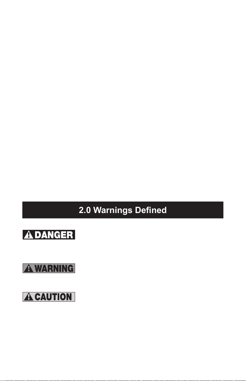
Danger: Indicates an imminently hazardous situation
that, if not avoided, will result in death or serious injury.
This signal word is limited to the most extreme situations.
Warning: Indicates a potentially hazardous situation that,
if not avoided, could result in death or serious injury.
Caution: Indicates a potentially hazardous situation that,
if not avoided, may result in minor or moderate injury. It
may also be used to alert against unsafe practices.
SDU Series Instruction Manual • 5English version
Page 6

3.0 Introduction
Congratulations on your choice of the SDU Uninterruptible Power System (UPS).
The SDU is a compact, “Off-Line” DIN rail mountable UPS, which provides conditioned power to sensitive electronic equipment. It supplies connected equipment
with stepped approximation to sinewave power to simulate the power generated
by the utility.
The SDU is a powerful, microprocessor-controlled UPS. Input voltage range is
80% to 110% (ideal protection for the critical connected loads). Battery charging
occurs automatically when ac power is applied, no need to switch ON the UPS.
When power fails, the UPS can be automatically turned OFF, as long as the
connected loads are not operating to save the battery energy. The SDU also
includes an automatic self-test feature to test the UPS function and battery. If the
battery is no longer useful, the unit will sound an alarm and an LED indicator will
illuminate.
NOTE: This equipment has been tested and found to comply with the limits for
a Class A digital device, pursuant to Part 15 of the FCC Rules. These limits are
designed to provide reasonable protection against harmful interference in an
industrial installation. This equipment uses, generates and can radiate radio
frequency energy and, if not installed and used in accordance with the instructions, may cause harmful interference with radio communications. However, there
is no guarantee that interference will not occur in a particular installation. If this
equipment does cause harmful interference to radio or television reception, which
can be determined by turning the equipment OFF and ON, the user is encouraged to try to correct the interference by one or more of the following measures:
• Reorient or relocate the receiving antenna.
• Increase the separation between the UPS and the receiver.
• Connect the UPS into a circuit different from that which the receiver is
connected.
• Consult the dealer or an experienced radio/TV technician for help.
SDU Series Instruction Manual • 6English version
Page 7
4.0 System Description
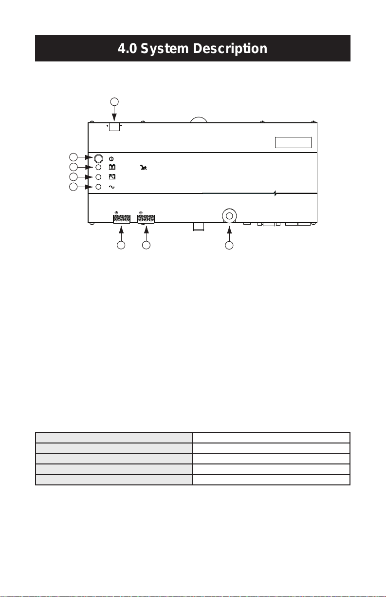
4.1 Front Panel
Surge Protection
Remote
Vout
N
Input:
Industrial UPS
S O L A
POWER ON / OFF / TEST
REPLACE BATTERY /
ON BATTERY (BACK UP MODE)
AC INPUT NORMAL (AC MODE)
OVERLOAD
Circuit Breaker
L N L
Output:
REMOTE
ON / OFF
+5V–30 V dc
+
–
1
2
3
4
5 6
7
8
1. Power ON/OFF/Test Button: Press the button for more than one second to
turn the UPS ON. Press the button for less than one second to activate the
self-testing. Press for more than ve seconds to turn OFF.
2. Battery Warning/Overload Indicator (Red LED): The LED flashes when the
battery needs to be recharged and tested. The LED will illuminate when the
unit is subjected to an overload condition. If the unit shuts down due to overload, the LED and alarm will continue for two minutes.
3. ON Battery Indicator (Yellow LED): The LED illuminates when the UPS is
supplying battery power to the loads.
4. Ac Input Normal Indicator (Green LED): The LED illuminates when the line
input voltage is normal.
5. IP20-rated Input Screw Terminals (see table below)
6. IP20-rated Output Screw Terminals (see table below)
Screw M3.0; Current rating = 30 A, Ac 300 V
Insulation Withstands Volts Ac 2000 V min.
PCB Hole Diameter 1.8 mm, wire strip length = 8 mm
Wire Range 10–24 AWG
Screw Torque 5.5 lb.-in.
7. Input Circuit Breaker: Protection from ac overload and short circuit.
8. Remote ON/OFF: The remote switch provides the same functions as the front
panel switch including ON/OFF/Test functions with Green Mode enabled or
disabled.
SDU Series Instruction Manual • 7English version
Page 8
4.0 System Description continued
9
10
11
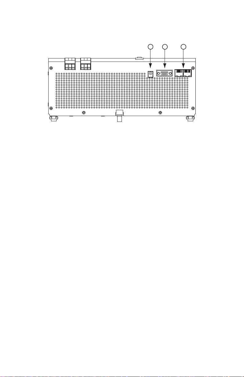
4.2 Bottom Panel
9. V Output: Output terminal providing 12 V power source to the optional
relay card.
10. Remote: RS232 communication port; DB-9 connector.
11. Tel/Surge Protection: Data line surge protection for phones (UL497A).
4.3 What’s Included
The SDU UPS is shipped with the following items:
• User manual
• UPSMON software CD
NOTE: Monitoring/diagnostic software is included on the UPSMON CD. The
software is compatible with Windows NT and Windows 2000 (including XP
operating systems).
• UPSMON DB-9 serial cable
• RJ-11 cord
• Electrical shock warning label
4.4 Accessories
• UPSMON-USB: RS232 to USB adapter cable
• RELAYCARD-SDU: Dry contact relay box
• SDU-PMBRK: Mounting brackets to secure the UPS to the wall, back of the
panel or enclosure
SDU Series Instruction Manual • 8English version
Page 9
5.0 Installation Instructions
1. Placement: Install the UPS in a protected area with adequate airflow and free
Risk of electrical shock—
hazardous live parts inside this
panel may be energized from the
battery supply, even when the
input ac power is disconnected.
6.0 Operating Instructions
of excessive dust. Do not operate the UPS outdoors.
2. Connect to Utility: To power up the UPS, connect the ac input connector to
the utility power.
3. Charge the Battery: The UPS charges its battery whenever it is connected to
utility power. For best results, charge the battery for four hours during initial use.
4. Connect the Loads: Connect the loads to the output hardwire connector.
5. Apply the Electrical Shock Warning Label: Apply the electrical shock
warning label to the panel, in a way that is clearly visible to the user.
1. Output Connector: The output connector will provide protection from surges
and power failures to the critical loads.
2. Switch ON Green Mode Enabled: After connecting the UPS to the utility
power, press the ON button until you hear the rst beep, then release the
button immediately. The Green Mode is enabled, i.e. if a load less than forty
watts (or no load) is connected and the UPS operates in the Backup Mode.
The UPS will enter into the Green Mode status after three minutes of backup
time; the green light will flash every three to ve seconds and after a short
period of time; and the unit will enter a “power save” status by shutting down
to prevent deep discharge of the battery. To reactivate the unit, power the unit
OFF then ON again or reapply utility power.
3. Switch ON Green Mode Disabled: After connecting the UPS to the utility
power, press the ON button and keep pressing it until you hear two short
beeps “Bi-Bip”, then release the button immediately. The Green Mode is now
disabled. Any kind of load, whether smaller than forty watts or larger, will not
affect the normal operation of the UPS under Ac or Battery Mode.
4. Switch OFF: To switch OFF the UPS, press and hold the Power ON/OFF/Test
button until the “Ac Power Normal” LED or “ON Battery” LED turns OFF.
SDU Series Instruction Manual • 9English version
Page 10
6.0 Operating Instructions continued
REMOTE
ON/OFF
5~30 Vdc
Remote Push
Button Switch
7.0 Battery Overload Alarms
5. Self-test: Use the self-test to verify both the operation of the UPS and the
condition of the battery. In normal utility power, push the Power ON/OFF/Test
button for less than one second; the UPS will perform a self-test. During the
self-test, the UPS runs in Backup Mode. If the UPS passes the self-test, it
returns to “Ac Input Normal” operation.
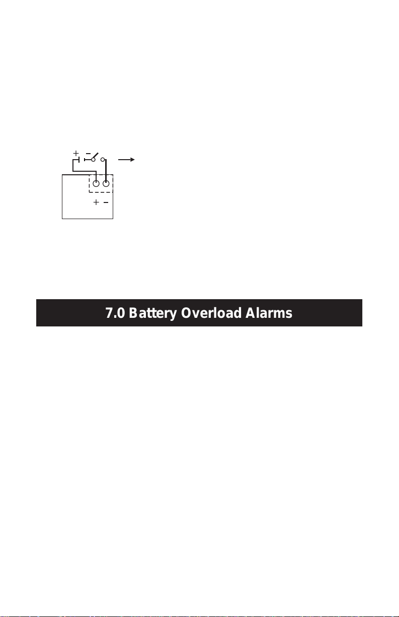
6. Remote ON/OFF: To ensure the remote ON/OFF function, connect a remote
push-button switch in series with 5–30 V dc voltage source to the ON/OFF
terminal as shown below.
The remote switch provides the same functions as the front panel switch
including ON/OFF/Test functions with Green Mode enabled or disabled. If the
Green Mode is not needed, a remote toggle switch can be used.
1. ON Battery (slow beeping): When in ON Battery Mode, the yellow LED illumi-
nates and the UPS sounds an audible alarm. The alarm stops when the UPS
returns to Ac Input Normal operation.
2. Low Battery (rapid beeping): In ON Battery Mode when the battery energy
runs low, the UPS beeps rapidly until the UPS shuts down from battery
exhaustion or returns to Ac Input Normal operation.
3. Overload (continuous alarm): When the UPS is overloaded (the connected
loads exceed the maximum rated capacity), the UPS sounds a continuous
alarm and LED to warn of an overload condition. Reduce the load to eliminate
the overload.
SDU Series Instruction Manual • 10English version
Page 11
8.0 PIN-Out Conguration for DB9 Connector
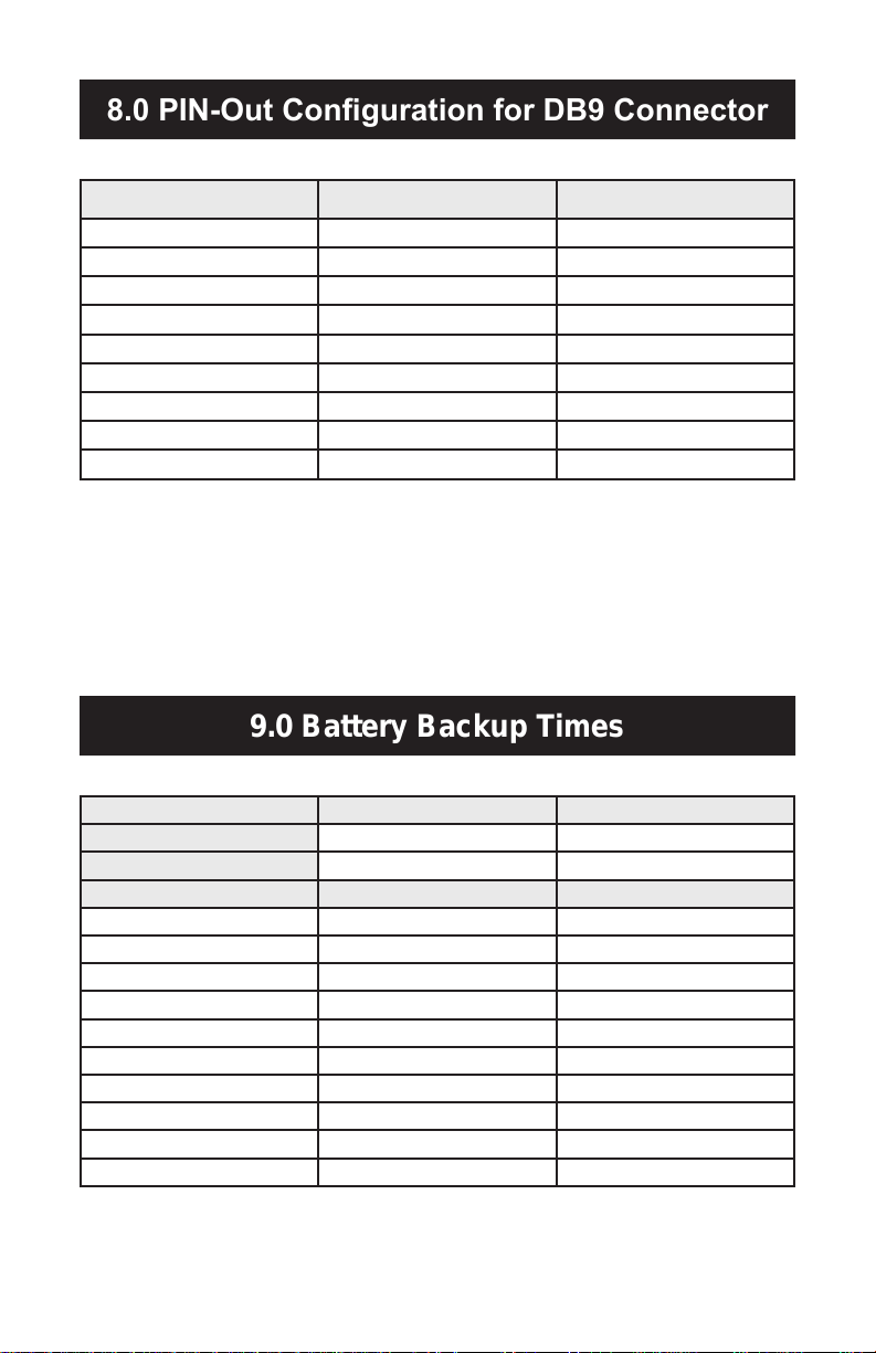
Female Connector PIN No. RS-232 Signal Open Collector Signal
9.0 Battery Backup Times
1 --- --2 TX --3 RD Remote shutdown*
4 DTR (+12 V) --5 GND GND
6 --- Ac failure
7 RTS (-12 V) --8 --- Battery low
9 TX ---
DTR = Data terminal ready
RTS = Request to send
RD = Transmitted data
GND = Signal Ground
TX = Received data
*When a remote shutdown signal is applied for one second, the UPS will shut down in three minutes.
SDU 500, SDU 500-5 SDU 850, SDU 850-5
VA/Watts 500/300 850/510
Battery YUASA NP7-12 YUASA REW45-12
Load Level Backup Time (Minutes) Backup Time (Minutes)
10% 130 80
20% 55 37
30% 36 20
40% 23 13
50% 18 10
60% 13 7
70% 10 5
80% 9 4
90% 6 3
100% 5 2.5
SDU Series Instruction Manual • 11English version
Page 12
10.0 Troubleshooting
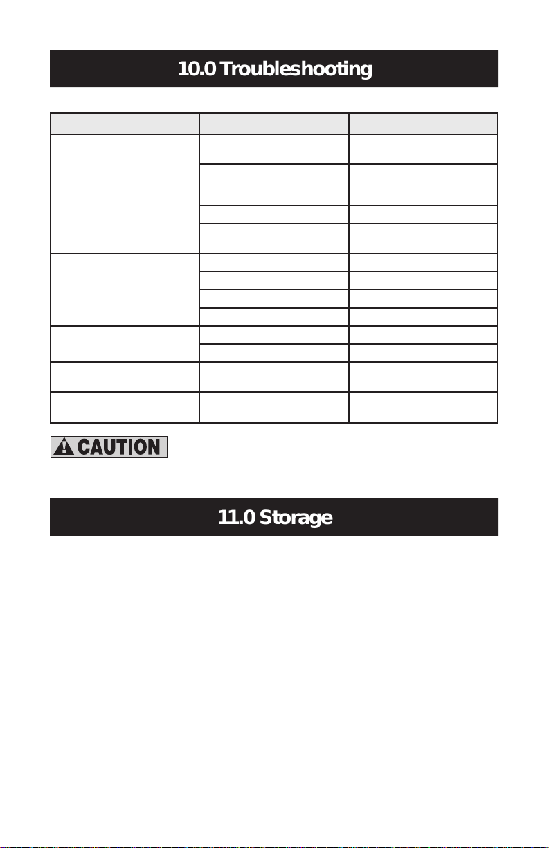
Problem Probable Cause Required Action
11.0 Storage
UPS is OFF or the ON/OFF/Test button
was not pushed for 1+ seconds
UPS is not ON; LED will not light
UPS is always in Backup Mode
Backup time is too short
Continuous beep & LED overload
indication
Red LED is ashing Battery failure
Battery voltage is less than 10 V
Other failure Call SolaHD Technical Support
Load is less than 20 W in Backup
Mode
Loose ac input power connection Tighten the ac power connection
Circuit breaker trips Reset the breaker
Line voltage too high, too low, or blackout Normal condition
Other failure Call SolaHD Technical Support
Battery is not fully charged Recharge the UPS for at least 4 hours
Other failure Call SolaHD Technical Support
Overload condition Remove the overload
Do not attempt to open the UPS or replace the battery. Call
SolaHD Technical Support for further instructions.
Press the ON/OFF/Test button for
more than 2 seconds
Recharge the UPS for at least 4 hours.
If the unit still does not start, check the
input fuse.
Normal condition
Recharge the UPS for at least 8 hours.
Perform UPS self-test.
11.1 Storage Conditions
Store the UPS covered and upright in a cool, dry location, with its battery fully
charged. Before storing, charge the UPS for at least four hours. Remove any
accessories in the accessory slot and disconnect any cables connected to the
computer interface port to avoid unnecessary draining of the battery.
11.2 Extended Storage
During extended storage in environments where the ambient temperature is -15
to +30 °C (+5 to +86 °F), charge the UPS battery every six months.
During extended storage in environments where the ambient temperature is +30 to
+45 °C (+86 to +113 °F), charge the UPS battery every three months.
SDU Series Instruction Manual • 12English version
Page 13

12.0 Specications
Description
INPUT
Capacity VA/Watts 500/300 850/510 500/300 850/510
Voltage (Single Phase) 120 V + 10%, -20% 230 V +/ -20%
Frequency 50 or 60 Hz, +/ -10% (auto-sensing)
OUTPUT
Voltage (on battery)
Frequency (on battery) 50 or 60 Hz, +/-0.5% auto-sensing
Transfer Time <4 milliseconds
PROTECTION
Unit Input Circuit breaker for overload and short circuit protection
Overload Protection UPS automatic shutdown if overload exceeds 105% of nominal at 20 s, 120% at 10 s, 130% at 3 s
Short Circuit UPS output cut off immediately
BATTERY
Type Sealed, maintenance-free, lead acid batteries
Typical Recharge Time
(to 90% of full capacity)
Backup Time
(at full load)
ALARM
ON Battery Slow beeping every 4 seconds
Battery Low Rapid beeping every second
Overload Continuous beeping sound
ENVIRONMENT
Ambient Operation 0–95% humidity, non-condensing. 50
Audible Noise <40 dBA (1 m from surface)
WEIGHT & DIMENSIONS
Net Weight, lb. (kg) 10.7 (4.7) 11.4 (5.0) 11.5 (5.2) 11.9 (5.4)
H x W x D, in. (mm) 4.88 x 11.1 x 4.55 (124 x 281 x 116)
SAFETY/APPROVALS
*For Conditions of Acceptability in accordance with UL 508A, see “13.0 Conditions for Safe Use of SDU 500 & 850”.
SDU 500 SDU 850 SDU 500-5 SDU 850-5
120 V +/-5% 230 V +/-5%
4 min. 2 min. 4 min. 2 min.
UL 1778 C-UL Recognized* for industrial
applications in accordance with UL 508A
without derating. Overvoltage Category 3,
Pollution Degree 3. FCC Part 15, Subpart B,
Class A.
Catalog Number
Simulated sine wave
8 hours
°
C up to 10,000 ft. (3000 m).
CE Marked; LVD: EN62040-1-1; EMC:
EN50091-2, EN61000-3-2, EN61000-3-3,
IEC801-2, IEC801-3, IEC801-4, IEC1000-2-2
SDU Series Instruction Manual • 13English version
Page 14

13.0 Conditions for Safe Use of SDU 500 & 850
NOTE: Applicable for U.S. only.
Considerations shall be given to the following:
1. The equipment shall be installed in compliance with the enclosure, mounting,
spacing, casualty, and segregation requirements of the ultimate application.
2. The equipment has been judged on the basis of the required spacings for
use in Overvoltage Category III and Pollution Degree 3 and in the Second
Edition of the Standard for Uniterruptible Power Supply Equipment, UL 1778,
par. 23 and table 23.1, which would cover the component itself if submitted
for unrestricted listing.
3. The suitability of grounding connection shall be determined in the end-use
product.
4. The equipment is provided with means for permanent mounting, the suit-
ability of assembly shall be determined in the end-use product.
5. Equipment is considered acceptable for use in a maximum ambient of 50°C.
6. The equipment inside live parts are energized from the battery supply even
when the input ac power is disconnected.
7. For CNR investigation, total harmonic distortion of 44.8% and maximum
single harmonic of 33.1%.
8. The equipment was investigated under 20 amperes branch circuit in accor-
dance with the National Electrical Code, ANSI/NFPA 70, to reduce the risk
of re, connect only to a circuit provided with 20 amperes maximum branch
circuit over current protection.
9. Use No. 18 AWG, 90°C copper wire and 9 lb.-in. Torque force when
connecting to terminal block.
10. Polarity Identication in UPS unit for led wiring terminals: Provided with
label adjacent to the unit supply connections. See below for details.
Input Output
N L N L
SDU Series Instruction Manual • 14English version
Page 15

14.0 Product Registration & Warranty Information
11. The following tests were additionally conducted at specied conditions as
noted below, in accordance with the Standard for Industrial Control Equipment, UL 508A, 17th Edition.
Temperature Test: Models SDU 850 and SDU 500 were mounted in an enclo-
sure (150% of the dimensions of the device, overall 420 by 180 by 160 mm),
in accordance with par. 42.6 of UL 508A. The suitability usage of industrial
control equipment shall be considered in end application.
Breakdown of Components Test: Model SDU 850 had been conducted through
a 30-ampere non-time-delay fuse, in accordance with par. 57.5 of UL 508A.
12. The products, Models SDU 850 and SDU 500 were evaluated based on
Pollution Degree 3 and Overvoltage Category III criteria and a minimum
end use ambient of 40°C, so that these devices do not have to be
derated when installed within an industrial control panel.
14.1 Product Registration
To register your product for updates and information on service and support:
• Visit the Technical Support section of our Web site at:
http://www.solahd.com/support/registration.htm
• Click on the Product Registration link and ll in the form. This will register your
product with SolaHD.
14.2 Warranty Information
Please see “Terms and Conditions of Sale”.
SDU Series Instruction Manual • 15English version
Page 16

1.0 Instrucciones importantes de seguridad
Este manual contiene instrucciones importantes de seguridad que deberán
seguirse durante la instalación del Sistema de Energía Eléctrica Ininterrumpible
(UPS). Por favor lea este manual completamente antes de intentar instalar u
operar este UPS.
Lea todas las instrucciones de seguridad, instalación y operación antes de
operar el UPS. Cumpla con todas las advertencias indicadas en la unidad y en
este manual. Siga todas las instrucciones de operación y deuso.
Este equipo está diseñado para uso Industrial o Comercial. Este equipo puede
ser instalado y operado por personas no capacitadas previamente para hacer
estas funciones.
1.1 Precauciones de seguridad—Advertencia
• Para evitar el riesgo de incendio o choque eléctrico, instale el UPS en una
habitación con temperatura y humedad controladas, libre de contaminantes
conductivos, humedad, líquidos inflamables, gases y sustancias corrosivas.
• Opere el UPS únicamente desde una fuente de suministro de CA debidamente
conectada a tierra (unida a tierra).
• Para reducir el riesgo de choque eléctrico, no retire la cubierta, ya que la
unidad no contiene piezas que el usuario puede reemplazar o reparar. Algunos
de los componentes tienen energía eléctrica, aún cuando la energía de CA
está desconectada. Para obtener servicio, póngase en contacto con un técnico
calicado.
Aunque su UPS ha sido diseñado y fabricado para garantizar la seguridad
personal del usuario, el uso indebido del mismo puede resultar en un choque
eléctrico o incendio. Para garantizar su seguridad, por favor observe las
siguientes normas:
• Apague el UPS y desconecte el suministro de energía de CA antes de limpiarlo.
No utilice limpiadores líquidos o aerosol. Se recomienda utilizar un trapo seco
para quitar el polvo de la super cie de su UPS.
• No instale ni opere su UPS en o cerca del agua.
• No coloque el UPS en un carro, soporte o mesa inestable.
• No coloque el UPS bajo la luz directa del sol o cerca de fuentes emisoras de calor.
Versión española Manual de la instrucción de la serie de SDU • 16
Page 17

• Para permitir una ventilación adecuada del UPS, no bloquee ni cubra los lados
2.0 Denición de advertencias
superior e inferior de la unidad.
• Nunca bloquee ni inserte ningún objeto en los ori cios de ventilación u otras
aberturas del UPS. Mantenga todas las aberturas de ventilación libre de
acumulaciones de polvo que puedan restringir el fl ujo del aire.
• Siga todas las advertencias e instrucciones marcadas en el UPS. No intente
darle servicio al UPS, ya que este no contiene ninguna pieza que usted pueda
reparar o reemplazar. Re era todas las reparaciones al personal de servicio
técnico cali cado.
• No deseche la batería o las baterías en el fuego. La batería podría explotar.
• No abra ni dañe la batería. El electrolito derramado es peligroso para la piel y
los ojos. Podría ser tóxico.
Si su UPS exhibe cualquiera de las siguientes condiciones, apague el UPS,
desconecte el suministro de energía de CA y póngase en contacto con su
distribuidor local, representante de SolaHD o Servicios Técnicos de SolaHD.
• Se ha derramado o vertido líquido en el UPS.
• El cortacircuito se abre frecuentemente.
• El UPS no funciona de acuerdo con el manual del usuario.
1.2 Condiciones de Uso
Su UPS le proporciona energía eléctrica acondicionada al equipo conectado. La
carga máxima no deberá exceder la capacidad indicada en la etiqueta o placa
del UPS. Si no está seguro, póngase en contacto con su distribuidor o SolaHD.
Peligro: Indica una situación de riesgo inminente que,
si no se evita, causará lesiones graves o letales. Esta
palabra de señal se utilizará sólo en las situaciones más
extremas.
Advertencia: Indica una situación potencialmente riesgosa, que si no se evita, podría causar lesiones graves o
letales.
Precaución: Indica una situación potencialmente riesgosa, que si no se evita, podría causar lesiones leves
o moderadas. También se puede utilizar para indicar
prácticas poco seguras.
Versión española Manual de la instrucción de la serie de SDU • 17
Page 18

3.0 Introducción
Felicitaciones por su elección de un Sistema de Energía Eléctrica Ininterrumpible
(UPS) de la Serie SDU Sola. Éste proporciona energía eléctrica acondicionada a
los equipos electrónicos sensibles.
La Serie SDU es un UPS compacto “Fuera de línea”, montable en Riel DIN. El
mismo le proporciona al equipo conectado una aproximación escalonada de
alimentación eléctrica sinusoidal para simular la energía generada por la fuente
pública.
La unidad SDU es un potente UPS controlado por microprocesador. La gama del
voltaje de entrada es de un 80% a un 110%, una protección ideal para las cargas
críticas conectadas. La recarga de la batería se realiza automáticamente cuando
se conecta el suministro de energía de CA, no es necesario encender (poner
en ON) el UPS. Cuando se corta la energía eléctrica, puede apagarse automáticamente el UPS si ninguna de las cargas conectadas está funcionando, para
conservar la energía de la batería. La unidad SDU incluye una función de auto-
comprobación automática que veri ca el funcionamiento del UPS y la batería.
Si se detecta que la batería ya no funciona, la unidad se pone en alarma y un
indicador LED se ilumina.
NOTA: Este equipo ha sido sometido a prueba y se ha determinado que cumple
con los límites para un dispositivo digital de Clase A, según la parte 15 de las
Normas de la FCC. Estos límites están diseñados para proporcionar una protección razonable contra las interferencias dañinas en una instalación industrial.
Este equipo utiliza, genera y puede emitir energía de radiofrecuencia y, si no
se instala y se utiliza de acuerdo con las instrucciones, es posible que pueda
causar interferencia dañina con las comunicaciones por radio. Sin embargo, no
hay ninguna garantía de que la interferencia no se producirá en una instalación
en particular. Si este equipo produce interferencia dañina en la recepción de las
señales de radio o televisión, lo cual puede determinarse apagando y encendiendo el equipo, el usuario debe tratar de corregir la interferencia mediante una o
más de las siguientes medidas:
• Vuelva a orientar o ubicar la antena de recepción.
• Aumente la separación entre el UPS y el receptor.
• Conecte el UPS en un circuito diferente al que esté conectado el receptor.
• Consulte con su distribuidor o un técnico especializado en radio/televisión para
obtener ayuda.
Versión española Manual de la instrucción de la serie de SDU • 18
Page 19

4.0 Descripción de sistema
4.1 Panel frontal
Surge Protection
Remote
Vout
N
Input:
Industrial UPS
S O L A
POWER ON / OFF / TEST
REPLACE BATTERY /
ON BATTERY (BACK UP MODE)
AC INPUT NORMAL (AC MODE)
OVERLOAD
Circuit Breaker
L N L
Output:
REMOTE
ON / OFF
+5V–30 V dc
+
–
1
2
3
4
5 6
7
8
1. Botón “POWER ON/OFF/TEST” (Encendido/Apagado/Prueba): Presione
el botón durante más de 1 segundo para encender el UPS. Presione el botón
durante menos de 1 segundo para activar la autocomprobación del UPS.
Presione el botón durante más de 5 segundos para apagar.
2. Indicador (LED ROJO) “BATTERY WARNING/OVERLOAD” (Advertencia
de Batería/Sobrecarga): El LED destella cuando es necesario recargar y
comprobar la batería del UPS. El LED se enciende cuando la unidad está en
condición de sobrecarga. Si la unidad se apaga debido a una condición de
sobrecarga, el LED y la alarma permanecerán activados durante 2 minutos.
3. Indicador (LED AMARILLO) “ON-BATTERY” (En Batería): El LED se
enciendecuando el UPS suministra energía de la batería a las cargas.
4. Indicador (LED VERDE) “AC INPUT NORMAL” (Entrada de CA Normal): El
LED se enciende cuando el voltaje de entrada de línea es normal.
5. Terminales de entrada con tornillos de capacidad IP20 (vea la tabla abajo)
6. Terminales de salida con tornillos de capacidad IP20 (vea la tabla abajo)
Tornillo M3.0, capacidad de corriente = 30 Amp CA 300V
Voltaje no disruptivo del aislamiento CA 2000 V mín.
Diámetro de agujero PCB 1.8 mm, longitud de alambre pelado = 8 mm
Gama de tamaños de alambre 10 a 24 AWG
Par torsor para los tornillos 5.5 libras - pulgada
7. Cortacircuito de entrada: Protección contra sobrecargas de CA y cortocircuitos.
8. Encendido/Apagado Remoto: El interruptor remoto proporciona las mismas
funciones que el interruptor en el panel frontal, incluyendo las funciones ON/
OFF/TEST con la modalidad verde habilitada o no habilitada.
Versión española Manual de la instrucción de la serie de SDU • 19
Page 20

4.0 La Descripción de Sistema continuó
9
10
11
4.2 Panel inferior
9. V Out (salida de voltaje): Terminal de salida que proporciona un suministro
de energía de 12 voltios a la tarjeta opcional de relés.
10. Remoto: Puerto de comunicación RS-232 con conector DB9.
11. Protección contra sobretensiones en la línea de teléfono: Protección
contra sobretensiones para línea de datos telefónica (UL497A).
4.3 Qué se incluye
El UPS SDU se envía con los siguientes artículos:
• Manual del usuario del SDU
• CD con el software UPSMON
NOTA: Junto con la unidad se suministran un CD UPSMON que incluye un
software de monitoreo y diagnóstico. El programa es compatible con Windows
NT y Windows 2000 (incluyendo el Protocolo XP).
• Cable serie UPSMON
• Cordón RJ-11
• Etiqueta de advertencia de descarga eléctrica
4.4 Accesorios
• UPSMON-USB: Cable de adaptación de RS232 a USB
• RELAYCARD-SDU: Caja de relés de contacto seco
• SDU-PMBRK: Soportes de montaje para sujetar el UPS en la pared, detrás de
un panel o en un recinto
Versión española Manual de la instrucción de la serie de SDU • 20
Page 21

5.0 Instrucciones de instalación
1. Ubicación: Instale el UPS en una zona protegida con un fl ujo de aire adec-
Risk of electrical shock—
hazardous live parts inside this
panel may be energized from the
battery supply, even when the
input ac power is disconnected.
6.0 Instrucciones de operación
uado y libre de polvo excesivo. No opere el UPS en el exterior.
2. Conecte el UPS a la fuente eléctrica pública: Acople el conector de entrada
de CA a la fuente de energía eléctrica pública para energizar el UPS.
3. Cargue la batería: El UPS recarga su batería siempre que está conectado a
la fuente de energía pública. Para obtener los mejores resultados, cargue la
batería durante 4 horas en el uso inicial de la unidad.
4. Conecte las cargas: Acople las cargas al conector cableado de salida.
5. Aplicar la etiqueta de advertencia de descarga eléctrica: Aplicar la etiqueta
de advertencia de descarga eléctrica al grupo de una manera que sea claramente visible para el usuario.
1. Conector de salida: El Conector de salida proporcionará protección
contra sobretensiones e interrupciones del suministro eléctrico a las cargas
críticas suyas.
2. Encendido con el ‘Modo verde’ habilitado: Luego de conectar el UPS
(Sistema de Energía Eléctrica Ininterrumpible) al suministro de energía
pública, presione el botón de encendido (ON) hasta que escuche el primer
pitido después de transcurridos menos de 3 segundos, y luego suéltelo de
inmediato. El modo Verde se encuentra habilitado, por ejemplo, si una carga
inferior a 40 vatios (o ninguna carga) está conectada y el UPS funciona en el
modo de respaldo, el UPS pasará al estado de modo verde luego de tran-
scurridos 3 minutos del tiempo de respaldo; la luz verde destellará cada 3
a 5 segundos y tras un corto período de tiempo, la unidad pasará al modo
de ‘ahorro de energía’ y se desactivará para impedir que la batería se descargue demasiado. Para reactivar la unidad, apague y encienda la unidad, o
reconecte el suministro de energía pública al UPS y la energía se encenderá
nuevamente.
Versión española Manual de la instrucción de la serie de SDU • 21
Page 22

6.0 Instrucciones de operación continuó
REMOTE
ON/OFF
5~30 Vdc
Interruptor del Boton
de Empuje Remoto
3. Encendido con el ‘Modo verde’ inhabilitado: Luego de conectar el UPS
(Sistema de Energía Eléctrica Ininterrumpible) al suministro de energía
pública, presione el botón de encendido (ON) y continúe presionándolo hasta
que escuche dos pitidos cortos; luego suéltelo de inmediato y el modo verde
quedará inhabilitado. Ningún tipo de carga, ya sea menor o mayor que 40
vatios, afectará de manera alguna el funcionamiento normal del UPS bajo el
modo batería o CA.
4. Apagado: Para apagar el UPS, presione y no suelte el botón Power ON/OFF/
Test (Encendido / Apagado /Prueba) hasta que se apague el LED “AC INPUT
NORMAL” (Entrada de CA Normal) o el LED “ON BATTERY” (En Batería).
5. Autocomprobación: Utilice la autocomprobación para veri car el funcio-
namiento del UPS y la condición de la batería.Con el suministro de energía
pública, presione el botón Power ON/OFF/Test (Encendido/Apagado/Prueba)
durante menos de 1 segundo y el UPS realizará la función de autocomprobación. Durante la autocomprobación, el UPS funciona en la modalidad de
respaldo (en batería). Si el UPS pasa la autocomprobación, éste regresa al
funcionamiento de Entrada de CA Normal (“AC INPUT NORMAL”).
6. Encendido/Apagado Remoto: Para asegurar la función CON./DESC.
alejada, conecte un interruptor de botón alejado en serie con fuente del voltaje
de 5~30 VDC con el terminal con./desc. según lo demostrado en la gura
siguiente.
El interruptor remoto proporciona las mismas funciones que el interruptor en
el panel frontal, incluyendo las funciones ON/OFF/TEST con la modalidad
verde habilitada o no habilitada. Si no necesita el modo verde, se puede usar
uninterruptor de palanca.
Versión española Manual de la instrucción de la serie de SDU • 22
Page 23

7.0 Tiempo de autonomía de la batería (Alarma)
1. “EN BATERÍA” (pitidos lentos): Cuando la unidad está en la modalidad EN
8.0 Configuración de disposición de
las clavijas del conector DB9
BATERÍA, el LED AMARILLO se enciende y el UPS emite una alarma audible.
La alarma cesa cuando el UPS regresa al funcionamiento con ENTRADA DE
CA NORMAL (AC INPUT NORMAL).
2. “BATERÍA BAJA” (pitidos rápidos): En la modalidad EN BATERÍA, cuando
la carga de energía de la batería está baja, el UPS emite pitidos rápidos hasta
que el UPS se apaga porque la batería ya no tiene carga o el UPS regresa al
funcionamiento con ENTRADA DE CA NORMAL (AC INPUT NORMAL).
3. “SOBRECARGA” (alarma continua): Cuando el UPS está en condición de
sobrecarga (las cargas conectadas ex-ceden la capacidad nominal máxima de
la unidad), el UPS emite un sonido de alarma continuo y un LED se enciende
y permanece encendido para advertir sobre la condición de sobrecarga.
Disminuya la carga para eliminar la condición de sobrecarga.
Número de clavija del
conector hembra DB9
1 --- --2 TX --3 RD Desactivación Remota*
4 DTR (+12 V) --5 GND GND
6 --- Fallo de CA
7 RTS (-12 V) --8 --- Batería Baja
9 TX ---
DTR = Terminal de datos listo
RTS = Petición para enviar
RD = Datos transmitidos
GND = Señal de Tierra
TX = Datos recibidos
*Cuando se aplica la señal de desactivación remota durante 1 segundo, el UPS se desactivará (o apagará) al cabo de 3
minutos.
Versión española Manual de la instrucción de la serie de SDU • 23
Señal RS-232 Señal de colector abierto
Page 24

9.0 Tiempo de reserva de la batería
SDU 500, SDU 500-5 SDU 850, SDU 850-5
10.0 Almacenamiento
VA/Watts 500/300 850/510
Batería YUASA NP7-12 YUASA REW45-12
Nivel de la carga Tiempo de reserva (Minutos) Tiempo de reserva (Minutos)
10% 130 80
20% 55 37
30% 36 20
40% 23 13
50% 18 10
60% 13 7
70% 10 5
80% 9 4
90% 6 3
100% 5 2.5
10.1 Condiciones de almacenamiento
Almacene el UPS cubierto y en posición vertical en un lugar seco y frío, con
su batería plenamente cargada. Antes de almacenarlo, cargue el UPS durante
4 horas como mínimo. Retire todo accesorio de la ranura de accesorios y
desconecte todo cable que esté conectado al puerto interfaz para computadora,
a n de impedir el drenaje innecesario de la batería.
10.2 Almacenamiento prolongado
Durante los almacenamientos prolongados en los entornos donde la temperatura ambiente es de -15 a +30°C (+5 a +86°F), cargue la batería del UPS cada
6 meses.Durante los almacenamientos prolongados en los entornos donde la
temperatura ambiente es de +30 +45°C (+86 +113°F), cargue la batería del UPS
cada 3 meses.
Versión española Manual de la instrucción de la serie de SDU • 24
Page 25

11.0 Solución de problemas
Problema Causa probable Acción a tomar
El UPS está apagado o no se ha
presionado el botón On/Off/Test
(Encendido/Apagado/Prueba) la
cantidad de tiempo suficiente
El UPS no enciende; el LED está
apagado
El UPS permanece en la modalidad
de respaldo (en batería)
Tiempo de respaldo demasiado
corto
Pitido continuo y se enciende el
LED de indicación de sobrecarga
LED rojo intermitente Fallo de la batería
Voltaje de batería inferior a 10V
Otra avería Llame a Servicios Técnicos
Carga inferior a 20 vatios en modali-
dad de respaldo (en batería)
Conexión de entrada de energía de CA
suelta o floja
El cortacircuito se dispara Reponga el cortacircuito
Voltaje de línea demasiado alto, de-
masiado bajo o se produjo un apagón
Otra avería Llame a Servicios Técnicos
La batería no está totalmente cargada
Otra avería Llame a Servicios Técnicos
Condición de sobrecarga Elimine la sobrecarga
No intente abrir el UPS ni reemplazar la batería. Llame a
Servicios Técnicos para obtener más explicaciones.
Presione el botón On/Off/Test (Encendido/Apagado/Prueba) durante más de
2 segundos
Recargue el UPS durante 4 horas
como mínimo. Si la unidad no en-
ciende, verifi que el fusible de entrada
Condición normal
Apriete la conexión de energía de CA
Condición normal
Recargue el UPS durante 4 horas
como mínimo
Recargue el UPS durante 8 horas
como mínimo, luego realice la autocomprobación del UPS
Versión española Manual de la instrucción de la serie de SDU • 25
Page 26

12.0 Especificaciones
Descripción
ENTRADA
Capacidad VA/Vatios 500/300 850/510 500/300 850/510
Voltaje (Monofásico) 120 V + 10%, -20% 230 V +/-20%
Frecuencia 50 ó 60Hz +/-10% (autodetección)
SALIDA
Voltaje (en batería)
Frecuencia (en batería) 50 ó 60Hz; +/-0.5% autodetección
Tiempo de transferencia <4 milisegundos
PROTECCIóN
Entrada de la unidad Cortacircuito para proteger contra sobrecargas y cortocircuitos
Protección contra
sobrecargas
Cortocircuito La salida del UPS se corta automáticamente
BATERÍA
Tipo Baterías selladas de plomo y ácido que no requieren mantenimiento
Tiempo de recarga
típico (hasta el 90% de
plena capacidad)
Tiempo de autonomía
en minutos a plena
carga
ALARMA
En batería Pitidos lentos a cada 4 segundos
Batería baja Pitidos rápidos cada segundo
Sobrecarga Sonido de pitido continuo
AMBIENTE
Operación ambiental 0-95% de humedad sin condensación; 50°C hasta 10,000 pies (3000 m)
Ruido audible <40 dBA (a 1 metro de la superficie)
PESO/DIMENSIONES
Peso neto, lb. (kg) 10.7 (4.7) 11.4 (5.0) 11.5 (5.2) 11.9 (5.4)
Altura x Anchura x
Profundidad, pulg. (mm)
SEGURIDAD/APROBACIONES
SDU 500 SDU 850 SDU 500-5 SDU 850-5
120 V +/-5% 230 V +/-5%
El UPS se apaga automáticamente si la sobrecarga excede el 105% del valor nominal a 20
segundos, 120% a 10 segundos, 130% a 3 segundos
4 min. 2 min. 4 min. 2 min.
4.88 x 11.1 x 4.55 (124 x 281 x 116)
Clasificación UL 1778 C-UL, reconocida para
aplicaciones industriales de acuerdo con
UL508 sin ninguna corrección. Categoría 3 de
sobrevoltaje, grado 3 de contaminación. Parte
15, Subparte B, Clase A de la FCC.
Modelo
Onda sinusoidal simulada
8 horas
Clasificación CE; LVD: EN62040-1-1;EMC:
EN50091-2, EN61000-3-2, EN61000-3-3,
IEC801-2, IEC801-3, IEC801-4, IEC1000-2-2
Versión española Manual de la instrucción de la serie de SDU • 26
Page 27

13.1 Registro del producto
13.0 Registro del producto y
información sobre la garantía
A n de registrar su producto para obtener actualizaciones e información sobre
servicio y apoyo:
• Visite la sección Apoyo Técnico o nuestro sitio Web en:
http://www.solahd.com/support/registration.htm
• Haga clic en el enlace de Registro de Productos y complete el formulario. Así,
su producto quedará registrado con SolaHD. Vous pourrez ainsi enregistrer
votre produit chez SolaHD.
13.2 Información sobre la garantía
Sírvase consultar “Términos y Condiciones”.
Versión española Manual de la instrucción de la serie de SDU • 27
Page 28

1.0 Instructions importantes sur la sécurité
Ce manuel contient des instructions importantes sur la sécurité, qui doivent être
respectées lors de l’installation de l’UPS. Veuillez lire attentivement ce manuel
avant de commencer à installer ou utiliser cet UPS.
Lire toutes les instructions sur la sécurité, l’installation et le fonctionnement avant
d’utiliser l’UPS. Respecter tous les avertissements indiqués sur l’appareil et
dans ce manuel. Suivre toutes les instructions d’utilisation et celles destinées à
l’utilisateur.
Cet équipement est conçu pour un usage industriel ou commercial. Cet équipement peut être installé et utilisé par des personnes n’ayant reçu aucune formation préalable.
1.1 Mesures de sécurité—avertissements
• An d’éviter les risques d’incendie ou de décharge électrique, installer l’UPS
dans une enceinte dont la température et l’humidité sont contrôlées, exempte
de contaminants conducteurs, d’humidité, de liquides et gaz infl ammables et
de substances corrosives.
• Utiliser l’UPS seulement à partir d’une source d’alimentation en courant alternatif correctement mise à la terre.
• An de réduire les risques de décharge électrique, ne pas enlever le couvercle,
car aucune pièce réparable par l’utilisateur ne se trouve à l’intérieur. Certains
composants sont sous tension, même lorsque l’alimentation c.a est coupée.
Pour obtenir du service, contacter un technicien qualié.
Bien que l’UPS ait été conçu et fabriqué pour assurer la sécurité personnelle,
une utilisation incorrecte peut entraîner une décharge électrique ou un incendie.
An d’assurer la sécurité, observer les règles suivantes :
• Mettre l’UPS hors tension et couper l’alimentation c.a avant de le nettoyer. Ne
pas utiliser de nettoyants liquides ou aérosols. On recommande d’utiliser un
chiffon sec pour enlever la poussière de la surface de l’UPS.
• Ne pas installer ou utiliser l’UPS dans ou à proximité d’un plan d’eau.
• Ne pas placer l’UPS sur un chariot, un support ou une table instable.
• Ne pas placer l’UPS sous les rayons directs du soleil ou à proximité d’une
source de chaleur.
Version française Manuel d’instruction de série de SDU • 28
Page 29

• Pour assurer une ventilation adéquate de l’UPS, ne pas bloquer ou recouvrir le
2.0 Dénition des avertissements
ATTENTION
dessus et les côtés inférieurs de l’appareil.
• Ne jamais bloquer ou insérer un quelconque objet dans les trous de ventilation
ou dans les autres ouvertures de l’UPS. Faire en sorte qu’aucune poussière
susceptible de restreindre le débit d’air ne s’accumule sur aucun des évents.
• Suivre tous les avertissements et les instructions apposés sur l’UPS. Ne pas
tenter de réparer l’UPS, aucune pièce réparable par l’utilisateur ne se trouve à
l’intérieur. Consulter du personnel quali é pour effectuer des réparations.
• Ne pas jeter la ou les batteries dans un feu. La batterie pourrait exploser.
• Ne pas ouvrir ou endommager la batterie. Une fuite d’électrolyte est nocive
pour la peau et les yeux. Ca peut être toxique.
Si votre UPS présente une des anomalies suivantes, mettre l’UPS hors tension,
couper l’alimentation c.a. et contacter votre distributeur local, un représentant
SolaHD ou les services techniques de SolaHD.
• En cas de liquide versé sur l’UPS.
• Le disjoncteur déclenche fréquemment.
• L’UPS ne fonctionne pas suivant les indications du manuel de l’utilisateur.
1.2 Conditions d’utilisation
Votre UPS fournit une l’alimentation conditionnée à l’équipement raccordé. La
charge maximale ne doit pas excéder celle indiquée sur l’étiquette. En cas de
doute, contacter votre distributeur ou SolaHD.
Danger: Indique une situation éminemment dangereuse
qui, si elle n’est pas évitée, peut causer la mort ou des
blessures graves. Ce signal n’est utilisé que pour les situ-
ations les plus dangereuses.
Avertissement: Indique une situation potentiellement
dangereuse qui, si elle n’est pas évitée, peut causer la
mort ou des blessures graves.
Attention: Indique une situation potentiellement
dangereuse qui, si elle n’est pas évitée, peut causer
des blessures légères ou modérées. Elle peut aussi être
utilisée pour mettre en garde contre les pratiques non
sécuritaires.
Version française Manuel d’instruction de série de SDU • 29
Page 30

3.0 Introduction
Félicitations pour avoir choisi l’UPS de Sola, série SDU. Il assure une
l’alimentation conditionnée aux l’équipements électroniques sensibles.
L’UPS de la série SDU est compact, « autonome », montable sur rail DIN. Il
fournit à l’équipement raccordé une approximation par étape de puissance
d’ondes sinusoïdales pour simuler la puissance générée par le fournisseur
d’électricité.
Le SDU est un UPS puissant commandé par microprocesseur. La plage de
tension d’entrée se situe entre 80 % et 110 %, une protection idéale pour les
charges critiques raccordées. La recharge de la batterie est automatique lorsque
l’alimentation c.a. est appliquée; aucun besoin de mettre l’UPS sous tension. En
cas de panne de courant, l’UPS peut être mis HORS TENSION automatiquement
si aucune des charges raccordées ne fonctionne, a n d’économiser l’énergie
de la batterie. Le SDU inclut une fonction d’auto-véri cation du fonctionnement
de l’UPS et de la batterie. Si la batterie n’est plus utile, l’appareil déclenche une
alarme et la DÉL s’allume.
REMARQUE : Cet équipement a été mis à l’essai et déclaré conforme aux
limites prévues pour un appareil numérique de classe A, conformément à la
partie 15 du règlement de la FCC. Ces limites ont pour but d’assurer une protec-
tion raisonnable contre une interférence nuisible dans une installation résiden-
tielle. Cet équipement utilise, génère et peut émettre de l’énergie en radiofréquence et, s’il n’est pas installé et utilisé conformé-ment aux directives, il peut
causer un brouillage nuisible dans les communications radio. Cependant, il est
impossible de garantir qu’aucune interférence ne se produira dans une installation particulière. Si cet équipement cause un brouillage de la réception de radio
ou de télévision (que vous pouvez déterminer en éteignant puis en rallumant
l’appareil), l’utilisateur est prié d’essayer d’éviter le brouillage au moyen de l’une
ou de plusieurs des mesures suivantes :
• Réorienter ou déplacer l’antenne de réception.
• Éloigner davantage l’UPS du récepteur.
• Raccorder l’UPS à un circuit différent de celui du récepteur.
• Consulter le concessionnaire ou un technicien en radio / télévision qualié pour
obtenir de l’aide.
Version française Manuel d’instruction de série de SDU • 30
Page 31

4.0 Description du système
4.1 Panneau avant
Surge Protection
Remote
Vout
N
Input:
Industrial UPS
S O L A
POWER ON / OFF / TEST
REPLACE BATTERY /
ON BATTERY (BACK UP MODE)
AC INPUT NORMAL (AC MODE)
OVERLOAD
Circuit Breaker
L N L
Output:
REMOTE
ON / OFF
+5V–30 V dc
+
–
1
2
3
4
5 6
7
8
1. Bouton « POWER ON/OFF/TEST » : Appuyer sur le bouton pendant plus
d’une (1) seconde pour mettre l’UPS sous tension. Appuyer sur le bouton
pendant moins d’une seconde pour activer l’auto-vérication de l’UPS.Appuy-
erpendant plus de 5 secondes pour mettre hors tension.
2. Voyant « BATTERYWARNING / OVERLOAD » (DÉL ROUGE) : La DÉLcli-
gnote lorsque la batterie de l’UPS doit être rechargée et vériée. La DÉL
s’allume lorsque l’appareil est en surcharge. Si l’appareil s’éteint suite à une
surcharge, la DÉL et l’alarme sont activées pendant 2 minutes.
3. Voyant « ON BATTERY » (DÉL JAUNE) : La DÉL s’illumine lorsque l’UPS
alimente les charges en courant de la batterie.
4. Voyant «AC INPUT NORMAL » (DÉL VERTE) : La DÉL s’allume lorsque la
tension d’entrée de ligne est normale.
5.Bornesàvisd’entréeclassifiéesIP-20 (voir le tableau ci-dessous)
6.BornesàvisdesortieclassifiéesIP-20 (voir le tableau ci-dessous)
Vis M3.0, courant nominal = 30A c.a. 300 V
L’isolation résiste à la tension c.a. 2000 V min
Diamètre du trou PCB 1,8 mm, longueur de dénudage de câble = 8 mm
Calibre du fil 10 ~ 24AWG
Couple de serrage des vis 5,5 lb - po
7. Disjoncteur du circuit d’entrée : Protection contre une surcharge de c.a. et
des courts-circuits.
8. Commande à distance marche/arrêt : La commande à distance marche/
arrêt offre les mêmes fonctions que L’interrupteur marche/arrêt sur le panneau.
Version française Manuel d’instruction de série de SDU • 31
Page 32

4.0 La description de système a continué
9
10
11
4.2 Panneau inférieur
9. Sortie V : Borne de sortie fournissant une source d’alimentation de 12 V à la
carte de relais en option.
10. Distant : Port de communication RS 232, connecteur DB9.
11. Protection contre Téléphone/surtension : Protection contre la surtension
de ligne de données pour téléphone (UL497A).
4.3 Ce qui est inclus
L’UPS SDU est expédié avec les articles suivants :
• Manuel utilisateur du SDU
• CD delogiciel UPSMON
REMARQUE : Le logiciel de surveillance / diagnostic est inclus sur le CD
UPSMON. Le programme est compatible avec Windows NT et Windows 2000,
incluant le protocole XP.
• Câble série UPSMON DB-9
• Cordon RJ-11
• Etiquette indiquant Choc électrique de mise en garde
4.4 Accessoires
• UPSMON-USB : RS232 à câble adaptateur USB
• RELAYCARD-SDU : Boîte à relais avec contact sec
• SDU-PMBRK : Supports de montage pour xer solidement l’UPS à un mur, à
l’arrière d’un panneau ou dans une enceinte
Version française Manuel d’instruction de série de SDU • 32
Page 33

5.0 Instructions d’installation
1. Placement : Installer l’UPS dans une zone protégée, avec une circulation
Risk of electrical shock—
hazardous live parts inside this
panel may be energized from the
battery supply, even when the
input ac power is disconnected.
6.0 Instructions d’utilisation
d’air adéquate et exempte de poussière excessive. Ne pas utiliser l’UPS à
l’extérieur.
2. Branchement à la source d’alimentation électrique : Brancher le connec-
teur d’entrée de c.a. au secteur pour mettre l’UPS sous tension.
3. Recharge de la batterie : L’UPS recharge sa batterie dès qu’il est branché
au secteur. Pour obtenir de meilleurs résultats, recharger la batterie pendant 4
heures avant son utilisation initiale.
4. Raccordement des charges : Raccorder les charges au connecteur câblé de
sortie.
5. Appliquer l’étiquette indiquant la mise en garde contre le choc électrique :
Appliquer l’étiquette indiquant la mise en garde contre le choc électrique sur le
panneau de façon à être clairement visible à l’utilisateur.
1. Connecteur de sortie : Le connecteur de sortie protège vos charges critiques
contre les surtensions et les pannes de courant.
2. Mise en marche avec le « Mode vert » activé : Après avoir connecté
l’UPS à l’alimentation secteur, appuyer sur le bouton de mise en marche «
ON » jusqu’à ce que le premier bip se fasse entendre après moins de trois
secondes, puis relâcher immédiatement le bouton. Le mode vert est activé,
c.-à-d. que si une charge inférieure à 40 watts (ou aucune charge) est
connectée et que l’UPS fonctionne en mode de secours; l’UPS passe en mode
vert après avoir été trois minutes en mode de secours; le voyant vert clignote
à toutes les trois ou cinq secondes, puis, après une brève période, passe
en mode « économie d’énergie » en s’éteignant pour éviter une décharge
excessive de la batterie. Pour réactiver l’appareil, le mettre hors tension puis
sous tension ou remettre l’alimentation secteur vers l’appareil après que
l’alimentation secteur soit revenue.
Version française Manuel d’instruction de série de SDU • 33
Page 34

6.0 Instructions d’installation continues
REMOTE
ON/OFF
5~30 Vdc
Commande à distance
par bouton-poussoir
3. Mise en marche avec le « Mode vert » désactivé : Après avoir connecté
l’UPS à l’alimentation secteur, appuyer sur le bouton de mise en marche «
ON » jusqu’à ce que deux bi-bip courts se fassent entendre, puis relâcher
immédiatement le bouton; le mode vert est désactivé. Toute charge, qu’elle
soit inférieure à 40 watts ou plus, ne modiera pas le fonctionnement normal
de l’UPS en mode c.a. ou de batterie.
4. Mise hors tension : Pour mettre l’UPS hors tension, maintenir enfoncé
le bouton POWER ON /OFF / TEST, jusqu’à ce que la DÉL « AC POWER
NORMAL » ou « ON BATTERY » s’éteigne.
5.Auto-vérification: Utiliser l’auto-vérication pour contrôler le fonctionnement
de l’UPS et l’état de la batterie. Si l’alimentation secteur est normale, appuyer
sur le bouton POWER ON / OFF / TEST pendant moins d’une (1) seconde et
l’UPS exécute une autovérication. Pendant l’auto-vérication, l’UPS fonctionne en mode de secours. Si l’UPS réussit l’auto-vérication, elle reprend
son mode de fonctionnement « AC INPUT NORMAL ».
6. Commande à distance marche/arrêt : Pour assurer la fonction commande
a distance marche/arrêt, connecter un interrupteur a bouton poussoir en série
avec une source de tension continue 5~30Vdc au bornes « On/Off » comme
indiqué sur la gure suivante :
La commande à distance marche/arrêt offre les mêmes fonctions que
L’interrupteur marche/arrêt sur le panneau. Si le mode vert n’est pas nécessaire, un interrupteur à bascule marche/arrêt peut être utilisé au lieu de
l’interrupteur à bouton poussoir.
Version française Manuel d’instruction de série de SDU • 34
Page 35

7.0 Alarmes de la batterie de secours
1.« ON BATTERY » (bip lent) : Lorsqu’en mode ON BATTERY, la DÉL JAUNE
8.0 Configuration des broches de
sortie du connecteur DB9
s’allume et l’UPS émet une alarme audible. L’alarme arrête lorsque l’UPS
retourne au mode de fonc-tionnementAC INPUT NORMAL.
2.« LOW BATTERY » (bip rapide) : En mode ONBATTERY,lorsque l’énergie
de la batterie faiblit,l’UPS émet un bip rapide jusqu’à ce que l’UPS arrête de
fonctionner en raison de l’épuisement de la batterie ou qu’il retourne au mode
de fonctionnementAC INPUT NORMAL.
3.« OVERLOAD » (alarme continue) : Lorsque l’UPS est surchargé (les
charges raccordées excèdent la capacité nominale maximale), l’UPS émet un
son d’alarme continu et la DÉL indique une condition de surcharge. Réduire la
charge pour éliminer la surcharge.
Connecteur UPS DB9
femelle, broche no
1 --- --2 TT --3 RD Coupure à distance*
4 DTR (+12 V) --5 TERRE TERRE
6 --- Défaillance c.a.
7 RTS (-12 V) --8 --- Batterie faible
9 TT ---
DTR = Terminal prêt
RTS = Demande d’émission
RD = Données transmises
TERRE = Retour commun du signal
TT = Données reçues
*Cuando se aplica la señal de desactivación remota durante 1 segundo, el UPS se desactivará (o apagará) al cabo de 3
minutos.
Version française Manuel d’instruction de série de SDU • 35
Signal RS-232 Signal de collecteur ouvert
Page 36

9.0 Temps de secours de batterie
SDU 500, SDU 500-5 SDU 850, SDU 850-5
10.0 Entreposage
VA/Watts 500/300 850/510
Batterie YUASA NP7-12 YUASA REW45-12
Niveau de charge Temps de secours (Minutes) Temps de secours (Minutes)
10% 130 80
20% 55 37
30% 36 20
40% 23 13
50% 18 10
60% 13 7
70% 10 5
80% 9 4
90% 6 3
100% 5 2.5
10.1 Conditions d’entreposage
Entreposer l’UPS en le recouvrant, en le plaçant en position verticale dans un
endroit frais et sec, avec la batterie à pleine charge. Avant d’entreposer, charger
l’UPS pendant au moins 4 heures. Enlever tous les accessoires de la fente aux
accessoires et débrancher tous les câbles connectés au port de l’interface ordinateur, a n d’éviter une décharge inutile de la batterie.
10.2 Entreposage de longue durée
Lors d’un entreposage prolongé dans un environnement où la température ambiante est de -15 à +30 °C (+5 à +86 °F), recharger la batterie tous les 6 mois.
Lors d’un entreposage prolongé dans un environnement où la température ambiante est de +30 à +45 °C (+86 à +113 °F), recharger la batterie tous les 3 mois.
Version française Manuel d’instruction de série de SDU • 36
Page 37

11.0 Dépannage
Probléme Cause Probable Action Corrective
ATTENTION
L’UPS est hors tension ou le bouton
ON / OFF / TEST n’a pas été enfoncé
suffi samment longtemps
UPS hors tension, la DÉL ne
s’allume pas
L’UPS est toujours en mode de
secours
Temps de fonctionnement en
secours trop court
Bip continu et indication de DÉL de
surcharge
La DÉL rouge clignote Défaillance de la batterie
La tension de la batterie est inférieure
à 10 V
Autre défaillance Appeler les services techniques
La charge est inférieure à 20 W en
mode de secours
Desserrer la connexion de
l’alimentation d’entrée de c.a.
Déclenchement du disjoncteur Réenclencher le disjoncteur
La tension de ligne est trop élevée,
trop faible ou en panne
Autre défaillance Appeler les services techniques
La batterie n’est pas complètement
chargée
Autre défaillance Appeler le service technique
Condition de surcharge Éliminer la surcharge
Ne pas essayer d’ouvrir l’UPS ou de remplacer la batterie.
Appeler les servic-es techniques pour obtenir des explications supplémentaires.
Appuyer sur POWER / ON / OFF /
TEST pendant plus de 2 secondes
Recharger l’UPS pendant au moins 4
heures. Si l’appareil ne se met toujours
pas en marche, vérifi er le fusible
d’entrée.
Condition normale
Resserrer la connexion d’alimentation
c.a.
Condition normale
Recharger l’UPS pendant au moins
4 heures
Recharger l’UPS pendant au moins
8 heures, effectuer l’auto-vérifi cation
de l’UPS.
Version française Manuel d’instruction de série de SDU • 37
Page 38

12.0 Spécifications
Description
ENTRÉE
Capacité V A / Watts 500/300 850/510 500/300 850/510
Tension (Monophasé) 120 V + 10%, -20% 230 V +/-20%
Fréquence 50 ou 60 Hz +/-10 % (auto-détection)
SORTIE
Tension (sur batterie)
Fréquence (sur batterie) 50 ou 60 Hz, +/-0,5% auto-détection
Temps de transfert < 4 millisecondes
PROTECTION
Entrée de l’appareil Disjoncteur protégeant contre les surcharges et les courts-circuits
Protection contre les
surcharges
Court-circuit La sortie UPS est coupée immédiatement
BATTERIE
Type Accumulateurs au plomb, sans entretien et hermétiques
Temps typique de
recharge (à 90 % de la
pleine charge)
Durée en utilisation
secours – minutes à
pleine charge
ALARME
Sur la batterie Bip lent toutes les 4 secondes
Batterie faible Bip rapide chaque seconde
Surcharge Bip continu
ENVIRONNEMENT
Fonctionnement à
température ambiante
Bruit audible < 40 dBA (1 mètre de la surface)
POIDS / DIMENSIONS
Poids net en kg (livres) 4,7 (10,7) 5,0 (11,4) 5,2 (11,5) 5,4 (11,9)
H x L x P, mm (po) 124 x 281 x 116 (4,88 x 11,1 x 4,55)
SÉCURITÉ / AUTORISATIONS
SDU 500 SDU 850 SDU 500-5 SDU 850-5
120 V +/-5% 230 V +/-5%
Coupure automatique UPS si la surcharge dépasse 105 % de la charge nominale à
20 secondes, 120 % à 10 secondes, 130 % à 3 secondes
4 min. 2 min. 4 min. 2 min.
0 à 95 % d’humidité, sans condensation50 °C jusqu’à 3000 m (10 000 pi)
Reconnu UL 1778 C-UL pour les applications
industrielles, conformément à UL508, sans
déclassement. Surtension de catégorie 3,
degré de pollution : 3. FCC, partie 15, souspartie B, classe A.
Modèle
Onde sinusoïdale simulée
8 heures
Marqué CE; LVD: EN62040-1-1;EMC:
EN50091-2, EN61000-3-2, EN61000-3-3,
IEC801-2, IEC801-3, IEC801-4, IEC1000-2-2
Version française Manuel d’instruction de série de SDU • 38
Page 39

13.1 Enregistrement du produit
13.0 Enregistrement du produit
et information sur la garantie
Pour enregistrer votre produit an de recevoir des mises à jour et de l’information
sur le service et le soutien :
• Visiter la section du Soutien technique sur notre site Web au :
http://www.solahd.com/support/registration.htm
• Cliquer sur le lien d’enregistrement du produit et remplir le formulaire. Vous
pourrez ainsi enregistrer votre produit chez SolaHD.
13.2 Informations sur la garantie
Veuillez voir le « Termes et conditions générales de Sale » .
Version française Manuel d’instruction de série de SDU • 39
Page 40

Technical Support
U.S.: (800) 377-4384
International: (847) 268-6000
E-mail: www.solahd.com
Servicio Técnico
EE.UU. (800) 377-4384
Internacional: (847) 268-6000
Correo electrónico: www.solahd.com
Assistance technique
États-Unis: (800) 377-4384
International: (847) 268-6000
Courriel: www.solahd.com
Part Number: A272-080 Rev 8
May 30, 2008
 Loading...