

Power Supplies
SDN-D High Performance DIN Rail Series
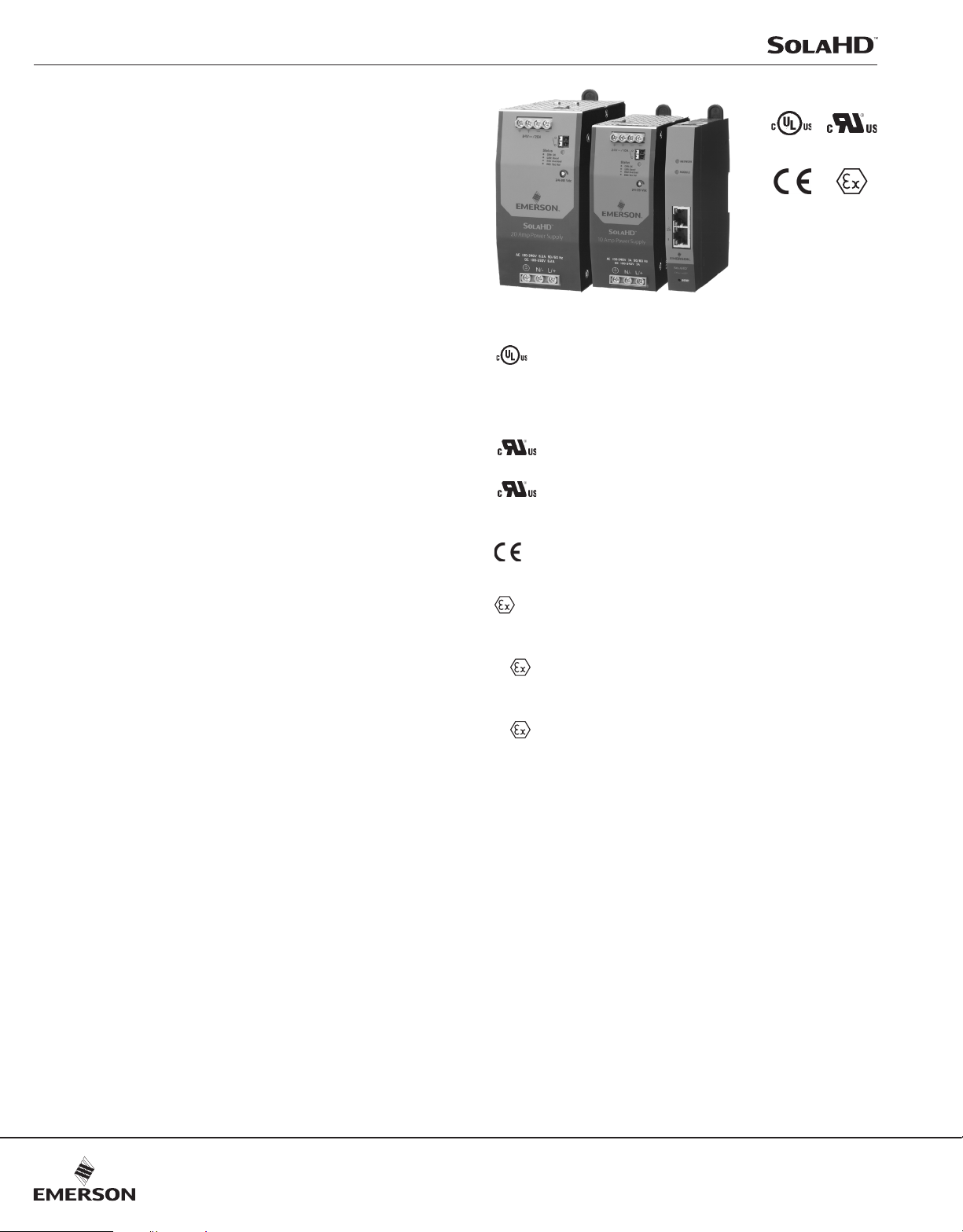
In spite of its small size, the SDN-D high performance DIN
rail power supply boasts one of the highest efciencies
available in the market today. Higher efciency means
less heat is generated, potentially extending the life of
all components in the enclosure. Extensive diagnostic
monitoring capabilities are possible with the optional SCM
network communication module, which utilizes popular
industrial network protocols to provide critical power supply
data to computers, PLCs, DCSs HMIs, and other devices.
For applications requiring even higher reliability, combine
the SDN-D with SDN redundancy modules. With its
extensive capabilities, compact design, and notable global
certications, the SDN-D is the ideal solution for use in harsh
environments, extreme temperatures (–40 °C to +70 °C),
and hazardous locations worldwide.
Applications
• Industrial Automation
• Process Control
• Material Handling and Conveyors
• Hazardous Locations
Features
• High performance unit in a compact package
• Optional network communications modules provides
important diagnostic information to controllers, HMI, and
computers
• Continuous Power Boost: Up to 120% continuous, for
temperatures up to 50 °C
• Multi-turn potentiometer simplies accurate setting of
output voltage
• Extensive international hazardous location certications,
including Class I Zone 2, ATEX, and IECEx. Hazardous
location temperature code (T-Code) rating of T4
• Inductive Load Power Boost additional short term
power, to assist in starting loads with high inrush current
• Dual output terminals for convenience in wiring
• DC OK relay to provide diagnostic information to a PLC,
controller, or monitoring system
• Circuit Interruption Power Boost provides short duration
peak current sufcient to trip properly-sized load side
fuse or circuit breaker in the event of a load fault
• Universal AC and DC input voltages to accommodate
global requirements
• Wide operating temperature range accommodates both
extreme hot and extreme cold environments
• Active Power Factor Correction greater than 0.98
• Parallel operation capability standard
• Supports redundant power supply operation using
optional SDN™ Redundancy modules
• 5-year limited warranty
* Refer to user manual for installation requirements when used in hazardous locations.
E61379
IECEx
Certifications and Compliances *
•
•
•
• - Low Voltage Directive
• ATEX Directive
Model SDN 10-24-100D
Model SDN 20-24-100D
• IECEx Certied
Model SDN 10-24-100D
Model SDN 20-24-100D
• RoHS (Europe, China)
Related Products
• IP67 SCP-X Standalone Power Supplies
• SDU UPS
Accessories
• SCM Network Communication Modules for
• SDN Redundancy Modules
• Chassis Mount Brackets
Listed, Electrical Equipment for Measurement,
Control and Laboratory Use; Control Equipment,
E61379
– UL 61010-1, UL 61010-2-201, CSA 61010-1,
CSA 61010-2-201
UL Recognized Component, ITE, E137632
– UL/CSA 60950-1, UL/CSA 62368-1
UL Recognized Component, Haz Loc, E234790;
Class I Div 2, Groups A, B, C, D T4
– UL 121201/CSA 213
– IEC/EN60950-1, IEC/EN 62368-1, IEC/EN 61010-1,
IEC/EN 61010-2-201
– EN IEC 60079-0, EN IEC 60079-7
– II 3 G, Ex ec IIC T4 Gc
– EN IEC 60079-0, EN IEC 60079-7, EN IEC 60079-15
– II 3 G, Ex ec nC IIC T4 Gc
– IEC 60079-0, IEC 60079-7; Ex ec IIC T4 Gc
– IEC 60079-0, IEC 60079-7, IEC 60079-15;
Ex ec nC IIC T4 Gc
Power Supplies
E137632
E234790
122
Visit our website at www.emerson.com or contact Technical Services at (800) 377-4384 with any questions.
© March 2021
Power Supplies
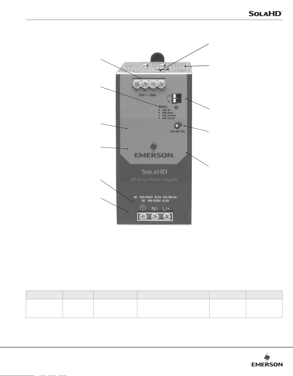
The SolaHD Difference
Multiple output connections for
ease of wiring multiple devices
Single two-color LED, with printed
status legend, provides intuitive
diagnostic information
Automatically adjusts to single or
parallel operation, no switch required
Clearly labeled front panel
Connection to optional SCM Network
Communication Module, to provide
extensive diagnostic capabilities
Rugged metal housing
DC OK Relay Terminals provide diagnostic
information to a PLC or controller
Multi-turn potentiometer, for precise
setting of desired output voltage
No internal fan, no extra cooling required
in any power level
Automatically adjusts for global
Multiple certications for
versatility in applications
Input voltages
Up to 31% narrower than SDN-C models
LED Light Status Conditions
Bi-color LED: Green indicates output power is present. Red indicates no output power due to power supply
protection circuitry.
OK Loss of AC Continuous Power Boost Inductive Load Power Boost Overload Too Hot
Green
(steady)
–
Green
(blinking)
Power alternatives On/Off:
Green (4s blinking): Output ON
Red (4s blinking): Output OFF
Red
(blinking)
Red
(steady)
Visit our website at www.emerson.com or contact Technical Services at (800) 377-4384 with any questions.
© March 2021
123
Power Supplies
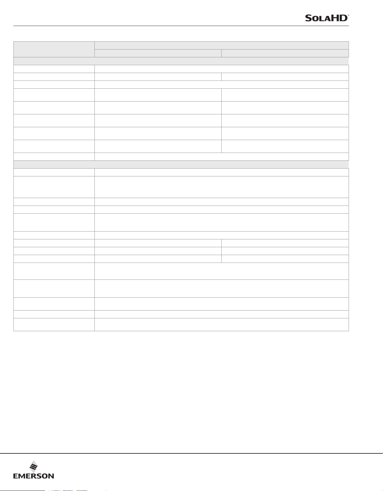
SDN-D Specifications (Single Phase)
Description
Nominal Input Voltage, AC (Range)
Nominal Input Voltage, DC (Range)
Frequency, AC Input
Input Current, AC
(typical value at 24.5 Vdc, 10A/20A output)
Input Current, DC
(typical value at 24.5 Vdc, 10A/20A output)
Typical Input Inrush current, AC
120 Vac, 25 °C, 100% full load current
Worst case Input Inrush current, AC
240 Vac, 60 °C, 100% full load current
Efficiency (Losses) at full load.
Losses are heat dissipation in watts
Power Factor Correction (PFC) at 25 °C
Output Voltage, Nominal
Output Voltage, Adjustable Range
Output Voltage, Initial Factory Setting
Output Voltage, Tolerance
Output Voltage Ripple, typical
(measured with a 20 MHz bandwidth scope
and 50 Ohm resistor)
Periodic and Random Deviation (PARD)
Nominal Output Current (Power)
Continuous Power Boost
High Temperature Output Power De-rating
Parallel Output Operation for increased
power (using similar SDN-D power supplies)
Parallel Output Operation for Redundancy
(using two similar SDN-D power supplies)
Turn On Time, after AC is applied to input,
25 °C
Holdup Time
Output Voltage Fall Time (from 95% to 10%
rated voltage, at full load, 25 °C)
Catalog Number
SDN 10-24-100D SDN 20-24-100D
Input
100 - 240 Vac (85-264 Vac)
100-300 Vdc (90-375 Vdc) 100-250 Vdc (90-275 Vdc)
43 - 67 Hz
3.0A at 100 Vac, 1.11A at 240 Vac 6.2A at 100 Vac, 2.19A at 240 Vac
3.0A at 100 Vdc, 0.85A at 300 Vdc 6.2A at 100 Vdc, 2.04A at 250 Vdc
<7A <10A
<10A <13A
93.7% 94.2%
Active PFC >0.98
Output
24 Vdc
Multi-turn potentiomenter: 3-turn (approximate)
Minimum range: 24-28 Vdc
Absolute Maximum: 28.8 Vdc
Typical Maximum: 28.6 Vdc
24.5 V ± 1%
< ±2 % overall
<50 mvpp
<100 mvpp
10A (240W) at +60 °C, continuous 20A (480W) at +60 °C, continuous
12A (288W) from -40 °C to +50 °C, continuous 22A (528W) from -40 °C to +50 °C, continuous
Linear derating from 240W to 216W power from +60 °C to +70 °C Linear derating from 480W to 360W power from +60 °C to +70 °C
Power supplies can be connected in parallel for increased power. However, for loads higher than 100% of individual SDN-D,
it is recommended that power supplies are initially powered up with no load applied. The outputs of SDN-D should also be adjusted
to <100mV of each other. Otherwise, unexpected results may occur due to differences in power up time for each power supply.
Yes, with SDN Redundancy modules.
Resistive load: < 1.0 sec
Capacitive load (7000μF): < 1.5 sec
> 20 msec
< 150 msec
NOTE: Unless otherwise noted, all specications apply to the full range of rated line, load, and temperature parameters, after 5 minutes run time. Convection cooled; no fans
required.
124
Visit our website at www.emerson.com or contact Technical Services at (800) 377-4384 with any questions.
© March 2021

Power Supplies
SDN-D Specifications (Single Phase)
Description
Inductive Load Power Boost
Circuit Interruption Power Boost
Short Circuit Protection
Back EMF Immunity
Overvoltage Protection
Overtemperature Protection
Surge Ratings
Emissions
Immunity
General Protection / Safety
Environmental Rating
Ingress Protection (IP) Rating
Temperature, Operating
Temperature, Storage
Humidity
Vibration
Shock
Altitude
Restriction on Hazardous Substances (RoHS)
Catalog Number
SDN 10-24-100D SDN 20-24-100D
Protection
Short duration: 1.5X for 4 sec
Peak Current: 6X for 15 msec at >19 V
Output automatically goes to near zero and output is protected from continuous short circuit. Auto-recovery.
< 35 V No damage, Auto-recovery
30.0 V maximum. Auto-recovery.
Output shutdown, LED Alarm. Auto-recovery.
Environmental Data
2kV L-N, 4kV L-PE, 4kV N-PE
(EN 61000-4-11, Criterion A)
EN61000-6-3, EN61000-6-4, EN 61326-1, EN55011, EN55032 Class B. EN61000-3-2, EN 61000-3-3
EN61000-6-1, EN61000-6-2, EN 61326-1, EN 55035, IEC 61000-4 Series (Level 4, Class A). SEMI F47 Sag Immunity
Protected against continuous short circuit, continuous overload, continuous open circuit.
IEC 62477-1: Overvoltage Category III, Pollution Degree II, up to 3000m. Overvoltage Category II from 3000-6000m
UL/CSA 60950-1, UL/CSA 62368-1, Overvoltage Category II, Pollution Degree II, SELV
UL/CSA 61010-1, UL/CSA 61010-2-201, Overvoltage Category II, Pollution Degree II
CB Report: IEC/EN 60950-1, IEC/EN 62368-1 Overvoltage Category II, Pollution Degree II, SELV
Pollution Degree II
IP20
From -40 °C to +70 °C. Refer to temperature-dependent de-rating and Continuous Power Boost specications in Output section.
Convection cooling
-40 °C to +85 °C
5 to 95 % RH Non-Condensing; IEC 60068-2-2, IEC 60068-2-3
2.5(g) RMS, 10-2000 Hz (random); three axes for 20 minutes each - IEC 60068-2-6
30g 6 msec, 20g 11 msec, 3-axis, 3 bumps/direction (18 bumps in total) - IEC 60068-2-27
0-3000 meters full power
Directive 2011/65/EU amended with Directive EU 2015/863, China RoHS
NOTE: Unless otherwise noted, all specications apply to the full range of rated line, load, and temperature parameters, after 5 minutes run time. Convection cooled; no fans
required.
Visit our website at www.emerson.com or contact Technical Services at (800) 377-4384 with any questions.
© March 2021
125

Power Supplies
SDN-D Specifications (Single Phase)
Description
MTBF: Telcordia SR-332 Issue 2 Method 1
Case 3
Operating Service Life
Fusing - Input
Fusing - Output
Mounting
Input Terminal Connections
Output Terminal Connections
DC OK Terminal Connections
Free Space - Above and Below
Free Space - Left and Right
Free Space - Front
Dimensions - WxDxH in (mm)
Weight - lbs (kg)
Case
Diagnostic Status Indicators
Warranty
1
Catalog Number
SDN 10-24-100D SDN 20-24-100D
Reliability
>773,575 hours @ 115 Vac, 25 °C
>869,055 hours @ 230 Vac, 25 °C
>527,547 hours @ 115 Vac, 40 °C
>584,514 hours @ 230 Vac, 40 °C
>304,000 hours @ 100 Vac input, 25 °C, 24 Vdc @ 10A output
>453,100 hours @ 230 Vac input, 25 °C, 24 Vdc @ 10A output
>198,600 hours @ 100 Vac input, 40 °C, 24 Vdc @ 10A output
>260,300 hours @ 230 Vac input, 40 °C, 24 Vdc @ 10A output
Internal non-replaceable fuse.
Outputs are capable of providing high currents for short periods of time for inductive load startup or switching. Fusing may be required
for wire/loads if 2x Nominal O/P current rating cannot be tolerated. Continuous current overload allows for reliable fuse tripping.
Simple snap-on to DIN TS35/7.5 or TS35/15 rail system.
Screw terminals. Connector size range: 16–10 AWG (1.5–6 mm2) for solid or stranded conductors.
Screw torque: 4.4-6.5 lb-inch (50-73 N-cm). Use only one copper wire per terminal.
Two terminals per output. Connector size range: 16–10 AWG (1.5–6 mm2) for solid or stranded conductors.
Screw torque: 4.4-6.5 lb-inch (50-73 N-cm). Use only one copper wire per terminal.
Connector size range: 16-24 AWG (1.5-0.25 mm2) solid or stranded conductors.
Use only one copper wire per terminal.
0.98 in (25 mm)
0.39 in (10 mm)
0.59 in (15 mm)
4.8 x 2.0 x 4.4 (123 x 50 x 111) 4.8 x 2.4 x 5.0 (123 x 60 x 127)
1.54 lbs (0.7 kg) 2.2 lbs (1.0 kg)
Fully enclosed metal housing with ne ventilation grid to keep out small parts.
Single 2-color LED
“DC OK” Relay: N.O. contact rated 50 Vdc, 1A. Signal Active when Vout> 18.5 Vdc +/-5%.
5 Year Limited Warranty
>114,600 hours @ 100 Vac input, 25 °C, 24 Vdc @ 20A output
>322,100 hours @ 230 Vac input, 25 °C, 24 Vdc @ 20A output
>56,000 hours @ 100 Vac input, 40 °C, 24 Vdc @ 20A output
>154,200 hours @ 230 Vac input, 40 °C, 24 Vdc @ 20A output
Installation
General
>944,000 hours @ 115 Vac, 25 °C
>1,048,000 hours @ 230 Vac, 25 °C
>609,000 hours @ 115 Vac, 40 °C
>837,000 hours @ 230 Vac, 40 °C
1. Based on the lifetime expectancy of the built-in electrolytic capacitors, as reported by the capacitor manufacturer’s specication. Values exceeding 131,400 hours are theoretical
calculations, provided for comparison purposes only.
NOTE: Unless otherwise noted, all specications apply to the full range of rated line, load, and temperature parameters, after 5 minutes run time. Convection cooled; no fans
required.
126
Visit our website at www.emerson.com or contact Technical Services at (800) 377-4384 with any questions.
© March 2021

Power Supplies
W
D
W
D
SDN-D Series Dimensions
H
Catalog Number
SDN-10-24-100D
SDN-20-24-100D
H
Dimensions - inches (mm)
H W D
4.8 (123) 2.0 (50) 4.4 (111)
4.8 (123) 2.4 (60) 5.0 (127)
Visit our website at www.emerson.com or contact Technical Services at (800) 377-4384 with any questions.
© March 2021
127

Power Supplies
1. Remove the M3X6 mm Phillips Screws, shoulder screw, plastic slide, spring
and C-Insert from the DIN Brackets.
DIN Bracket
2. Retain and slide back the two DIN brackets to use as a guide for the installation
of the panel mount brackets.
3. Push and slide the panel mount brackets on the top of DIN bracket and secure
with M3X8 mm Phillips Screw and lock washer (use 7kgf torque).
C-Insert
Spring
Plastic slide
Shoulder screw
M3X6 mm
Phillips Screw
DIN Bracket
Panel Mount Brackets Installation
Power Supply Accessories
SDN-PMBRK3
Panel Mount Brackets Installation Manual
P/N: A272-289 REV. 1 (07/16)
©2016 Appleton Grp LLC d/b/a Appleton Group
All rights reserved. Specifications
subject to change without notice.
Dimensions in Inches (Millimeters)
1. Remove the M3X6 mm Phillips Screws and C-Insert from the DIN Brackets.
This set consists of two panel mount brackets, which replace the existing two
DIN mounting brackets at the back of the unit.
FOR USE WITH:
CHASSIS MOUNTING
SDN 5-24-100C
SDN 10-24-100C
SDN 40-24-100C
SDN 10-24-480C
SDN 2X20RED
DIN Bracket
2. Retain and slide back the two DIN brackets to use as a guide for the installation
of the panel mount brackets.
3.
Push and slide the panel mount brackets on the top of DIN bracket and secure
with M3X10 mm Phillips Screw and lock washer (use 7kgf torque).
Two M3x10 mm phillips screws
Two brackets
Two M3 lock washers
Four 8-32 x 1/2” screws for mounting unit to panel
Four 8-32 flat washers
INCLUDED:
NOT INCLUDED:
C-Insert
M3X6 mm
Phillips Screw
DIN Bracket
Panel Mount Brackets Installation
7 9
83472 00651
1.93 (49.0)
Top View 3D View
1.65 (41.9)
CAUTION:
Risk of Electric Shock and Personal Injury
Ensure unit is disconnected from all power
sources prior to replacing brackets.
Panel Mount
Bracket
DIN Bracket
Lock washers
M3X10 mm
Phillips Screw
SDN-D Series Mounting
SolaHD SDN-D power supplies are designed to be easily and reliably mounted to DIN rail. For applications requiring
mounting the power supply directly to the panel, optional Panel Mount Adapter Brackets are available.
DIN Rail Mounting
Snap on the DIN rail:
1. Tilt unit slightly backwards. Put it onto the DIN rail
3. Push downwards until stopped
4. Push at the lower front edge to lock
5. Shake the unit slightly to ensure that the retainer
has locked
Panel Mounting
Panel mounting of SDN-D power supplies is simplied by using an optional SDN-PMBRK3 Panel Mounting Bracket kit.
Each kit comes with two brackets for screw mounting one power supply to a panel. Note that the Panel Mount bracket will
add approximately 2-4mm in depth, compared to DIN rail mounting. Refer to the manual that comes with the bracket kit for
detailed instructions on assembly and mounting.
SDN-PMBRK3
Power Supply
SDN 10-24-100D
SDN 20-24-100D
Panel Mount
Bracket
DIN Bracket
Back View
M3X8 mm
Phillips Screw
Detachment from DIN Rail:
Dimensions - in. (mm)
Top View 3D View
128
Visit our website at www.emerson.com or contact Technical Services at (800) 377-4384 with any questions.
© March 2021
 Loading...