

Page 1

Quick Start Guide
00825-0100-4210, Rev AB
Rosemount™ Wireless Permasense
WT210 Corrosion Transmitter
July 2019
Page 2

Quick Start Guide July 2019
NOTICE
This guide provides basic guidelines for the installation of the Rosemount™ Wireless Permasense
Corrosion Transmitter. It does not provide instructions for configuration, diagnostics, maintenance,
service, troubleshooting or intrinsically safe (I.S.) installations. Refer to the Rosemount Wireless
Permasense Corrosion Transmitter Reference Manual for more instruction. The manual and this guide
are also available electronically on Emerson.com\Rosemount.
Shipping considerations
Each device contains two “D” size primary lithium-thionyl chloride battery cells. Primary lithium
batteries are regulated in transportation by the U.S. Department of Transportation, and are also
covered by IATA (International Air Transport Association), ICAO (International Civil Aviation
Organization), and ARD (European Ground Transportation of Dangerous Goods). It is the responsibility
of the shipper to ensure compliance with these or any other local requirements. Consult current
regulations and requirements before shipping.
WARNING
Explosions could result in death or serious injury.
Installation of this transmitter in an explosive environment must be in accordance with the
appropriate local, national, and international standards, codes, and practices. Review the approvals
section of this manual for any restrictions associated with a safe installation.
Before connecting a CC21 in an explosive atmosphere, make sure the instruments in the segment
are installed in accordance with intrinsically safe or non-incendive field wiring practices.
This device complies with Part 15 of the FCC Rules. Operation is subject to the following
conditions:
This device may not cause harmful interference.
This device must accept any interference received, including interference that may cause undesired
operation.
This device must be installed to ensure a minimum antenna separation distance of 20 cm (8 in.)
from all persons.
The power module may be replaced in a hazardous area.
The power module has surface resistivity greater than one gigaohm and must be properly installed
on the wireless device. Care must be taken during transportation to and from the point of
installation to prevent a potential electrostatic charging hazard.
Polymer enclosure has surface resistivity greater than one gigaohm.
Care must be taken during transportation to and from the point of installation to prevent a potential
electrostatic charging hazard.
WARNING
Physical access
Unauthorized personnel may potentially cause significant damage to and/or misconfiguration of
end users’ equipment. This could be intentional or unintentional and needs to be protected against.
Physical security is an important part of any security program and fundamental to protecting your
system. Restrict physical access by unauthorized personnel to protect end users’ assets. This is true
for all systems used within the facility.
2 Emerson.com/Rosemount
Page 3

July 2019 Quick Start Guide
Contents
Overview......................................................................................................................................5
Wireless considerations................................................................................................................7
Field communicator connections................................................................................................. 8
Physical installation...................................................................................................................... 9
Commissioning device............................................................................................................... 12
Additional hardware...................................................................................................................16
Product certifications................................................................................................................. 19
Quick Start Guide 3
Page 4

Quick Start Guide July 2019
4 Emerson.com/Rosemount
Page 5

July 2019 Quick Start Guide
1 Overview
Figure 1-1: Rosemount™ Wireless Permasense WT210 Corrosion
Transmitter
A. Antenna
B. Power module
C. Head
D. Waveguide
E. Waveguide spacer
F. Stabilizer
G. Foot
H. Thermocouple
Quick Start Guide 5
Page 6

Quick Start Guide July 2019
1.1 Required equipment
Measuring tape
Standard tools (e.g., screwdriver,
wrench, pliers)
IK220
1.2 Hardware not supplied
• Full plain nuts, to suit welded stud thread and metallurgy:
— Thread: M8 or 5/16 in.
— Material: Stainless steel — or suitable other corrosion resistant steel
• Socket for 5/16-in. nuts
1.3
6 Emerson.com/Rosemount
What's in the box
• Rosemount™ Wireless Permasense WT210 transmitter
• Rosemount Permasense BP20E power module, including two M3 x 16
mm stainless steel retaining bolts
• Stainless steel circular heat shield
• M8 (compatible with 5/16-in. studs) Nord-Lock anti vibration washers,
two per sensor
• Lanyard kit, 316 stainless steel lanyard 6.5 ft. (2 m) in length, gripple
No.2, release key
Page 7

July 2019 Quick Start Guide
2 Wireless considerations
Power up sequence
The Emerson Wireless Gateway should be installed and functioning properly
before any wireless devices are powered. Commission the Rosemount
Wireless Permasense WT210 and install the BP20E power module to power
the device only (following instructions below) after the gateway has been
installed and functioning. This results in a simpler and faster network
installation. Enabling active advertising on the Gateway ensures new devices
are able to join the network faster. For more information see the Emerson
Wireless 1420 Gateway Manual (document number 00809-0200-4420).
Antenna position
The antenna is internal to the Rosemount Wireless Permasense WT210
transmitter. The antenna should also be approximately 3 ft. (1 m) from any
large structure, building, or conductive surface to allow for clear
communication to other devices.
Quick Start Guide 7
Page 8

Quick Start Guide July 2019
3 Field communicator connections
The CC21 commissioning cable is connected and removed from the
transmitter in the same way as the Rosemount ™ BP20E power module. The
USB connector is plugged in to the tablet PC as shown in Figure 3-1.
Figure 3-1: IK220 Commissioning Kit
A. Tablet PC
B. CC21
C. USB cable plugged into USB port
D. Rosemount™ Wireless Permasense WT210/ET210 sensor
8 Emerson.com/Rosemount
Page 9

July 2019 Quick Start Guide
4 Physical installation
The corrosion transmitter is connected directly to the piping being
measured.
Mounting considerations
Procedure
1. When mounting sensors on pipe bends and elbows, studs must be
aligned as follows
a) Fit two nuts to the stud, the first at the top of the thread and
the second 15-20 mm down the thread as shown in Figure
4-1.
b) Use M13 deep hex socket with extension bar to bring the
studs parallel to each other and perpendicular to the pipe
surface at the center point between the two studs.
c) Correct stud alignment will ensure the correct orientation of
the nut and washer with respect to the sensor foot.
Figure 4-1: Orientation
2. Observe the sensor contact from the side. As shown in the following
illustrations, check that:
a) Sensor feet are parallel to the pipe surface.
b) Studs are perpendicular to the pipe surface.
c) Sensor tip is in the middle of the two studs.
Quick Start Guide 9
Page 10

Quick Start Guide July 2019
Figure 4-2: Improper Installations of the Metal Standoffs
4.1 Mounting
For pipe clamp mounting, see clamp installation guide.
Procedure
1. On painted pipe-work, remove a singular patch of the coating about
1-in. (25 mm) diameter midway between the studs to allow
waveguides to contact pipe directly.
2. On straight pipes, ensure the studs are perpendicular to the sensor
contact point.
3. Apply Loctite® 8009 anti-seize compound to the threads.
4. Record the installation location, sensor ID, MAC address of the
sensor, and power module serial number.
5. Examine the thermocouple and make sure it is protruding past the
end of the waveguide by about ⅛ in. (3mm) so that it will press onto
the pipe when the sensor is tightened as shown in Figure 4-3.
10 Emerson.com/Rosemount
Page 11

July 2019 Quick Start Guide
Figure 4-3: Thermocouple Guidelines
Correct Incorrect
6. Locate and place the WT210 sensor over the studs, ensuring the
waveguides are positioned centrally to +/-0.2 in. (5 mm).
7. Place washers over the studs.
8. Thread nut onto the studs and run them down several threads.
9. Carefully secure the sensor in this position by finger tightening each
nut after observing the sensor in Figure 4-4.
Figure 4-4: Equal Spacing Guidelines
Quick Start Guide 11
Page 12

Quick Start Guide July 2019
5 Commissioning device
Mechanical installation and validation procedure
Procedure
1. Power up the rugged tablet PC and connect the CC21.
2. Double-click the Rosemount™ Wireless Permasense WT210
installation app desktop icon. Within approximately 10 seconds, the
installation tool software should open.
3. Attach the CC21 to the sensor.
4. In the Rosemount WT210 in installation app software, as seen in
Figure 5-1:
a) Select the Provision tab.
b) Enter the five-digit network ID and the 32 hexadecimal
(numbers 0-9 and letters A-F) join key.
c) Click the Provision button. Confirmation is given when
provisioning is complete.
d) Check in the Network Discovery panel to confirm that the
sensor can hear a device with the network ID you wish the
sensor to join.
Note
Joining the device to the network could take several minutes.
Figure 5-1: Rosemount WT210 Install Tool
12 Emerson.com/Rosemount
Page 13

July 2019 Quick Start Guide
CAUTION
Overtightening the nuts can damage the waveguides.
Torque wrench setting value of 8Nm (6ft.lbs) and ensure nuts are
ONLY tightened incrementally as described below.
5. Select the Install tab.
6. Select Start.
7. Observe the graphical information displayed in the install tool
software as shown in Figure 5-2.
a) As the sensor is tightened and becomes coupled to the pipe,
the coupling amplitude will rise in line with each ¼ turn
tightening of the nuts.
b) At 10 seconds after the start button is pressed, an ultrasonic
waveform will appear in the bottom window. This waveform
is continuously updated every 10 seconds.
c) The ultrasonic waveform will comprise several peaks. It is
important that the first TWO peaks are clean and well
defined, as illustrated in the example.
8. Continue to tighten each nut in ¼ turn increments, alternating
between nuts until torque is reached on each nut. Continue to
monitor the install tool software during this process.
Quick Start Guide 13
Page 14

Quick Start Guide July 2019
Figure 5-2: Rosemount W210 Installation Tab
A. Ultrasonic signal strength varying with time. Updated every 1
second.
B. Minimum installation amplitude. At the end of installation, the
graph must be ABOVE this line.
C. Plot of ultrasonic waveform (green) and the "envelope" of the
signal (blue). Updated every 10 seconds.
D. Click to pause the install; re-click to continue.
E. Click to complete the sensor installation. It will then try to join its
network.
5.1
14 Emerson.com/Rosemount
Complete the sensor installation
Procedure
1. Review the graphs following tightening and check these criteria are
met:
a) The coupling amplitude history plot shows an increasing
trend, in-line with nut tightening.
b) The coupling amplitude is above 20.
c) The last displayed ultrasonic waveform shows the first two
peaks are clean and well defined.
Page 15

July 2019 Quick Start Guide
d) The measured thickness displayed in the bottom right of the
window is comparable with expectations for the
measurement location.
2. When all of the above criteria are satisfactorily met, press the
Complete button.
3. Ensure all required sensor information is accurately logged (e.g.
sensor ID and location).
4. Remove the CC21 and fit the power module.
Note
When the power module is fitted, the sensor will restart and try to
join the WirelessHART® gateway. In a large network of 100 sensors,
this can often take two hours and sometimes up to six hours.
Quick Start Guide 15
Page 16

Quick Start Guide July 2019
6 Additional hardware
6.1 Lanyard installation
Procedure
1. Wrap the lanyard around the circumference of the pipe. The 6.6 ft. (2
m) length of lanyard will accommodate a maximum diameter of 20
in. (51 cm). When it is not possible to wrap the lanyard around a pipe,
find an alternative attachment point for the lanyard.
Figure 6-1: Lanyard Installation to Pipe/Fixed Attachment Point
2. Thread the bare end of the lanyard through the lanyard loop to
secure it to the pipe as shown in Figure 6-1.
Figure 6-2: Gripple Installation
3. Feed the bare end of the lanyard into the gripple as shown in Figure
6-2 and push the gripple 18 in. (45 cm) in from the bare end.
16 Emerson.com/Rosemount
Page 17

July 2019 Quick Start Guide
Figure 6-3: Lanyard Installation
A. Lanyard hole in sensor housing
B. Stabilizer
4. Feed the bare end of the lanyard through either lanyard hole in the
sensor housing, then through the stabilizer (between the
waveguides) as shown in Figure 6-1
5. Feed the bare end of the lanyard into the return hole of the gripple.
Adjust the gripple to minimize the slack in the lanyard cable between
the attachment point and the sensor.
Quick Start Guide 17
Page 18

Quick Start Guide July 2019
Figure 6-4: Gripple Installation Complete
Note
The wire can be released from the gripple using the release key.
Figure 6-5: Wire Release
A. Release key
18 Emerson.com/Rosemount
Page 19

July 2019 Quick Start Guide
7 Product certifications
Rev: 0.1
7.1 European Directive Information
A copy of the EU Declaration of Conformity can be found at the end of the
Quick Start Guide. The most recent revision of the EU Declaration of
Conformity can be found at Emerson.com/Rosemount.
7.2 Telecommunications Compliance
All wireless devices require certification to ensure they adhere to regulations
regarding the use of the RF spectrum. Nearly every country requires this type
of product certification. Emerson is working with governmental agencies
around the world to supply fully compliant products and remove the risk of
violating country directives or laws governing wireless device usage.
7.3 FCC and IC
This device complies with Part 15 of the FCC Rules. Operation is subject to
the following conditions: This device may not cause harmful interference.
This device must accept any interference received, including interference
that may cause undesired operation. This device must be installed to ensure
a minimum antenna separation distance of 20 cm from all persons.
7.4 Ordinary Location Certification
As standard, the transmitter has been examined and tested to determine
that the design meets the basic electrical, mechanical, and fire protection
requirements by a nationally recognized test laboratory (NRTL) as accredited
by the Federal Occupational Safety and Health Administration (OSHA).
7.5
North America
The US National Electrical Code® (NEC) and the Canadian Electrical Code
(CEC) permit the use of Division marked equipment in Zones and Zone
marked equipment in Divisions. The markings must be suitable for the area
classification, gas, and temperature class. This information is clearly defined
in the respective codes.
7.6
USA
I5 U.S.A. Intrinsicially Safe (IS)
Certificate:
Quick Start Guide 19
SGSNA/17/SUW/00281
Page 20

Quick Start Guide July 2019
Standards:
Markings:
UL 913 - 8th Edition, Revision Dec 6 2013
CLASS I, DIV 1, GP ABCD, T4, Tamb = -50 ˚C to +75 ˚C, IP67
Canada
I6 Canada Intrinsicially Safe (IS)
Certificate:
Standards:
Markings:
SGSNA/17/SUW/00281
CAN/CSA C22.2 No. 157-92 (R2012) +UPD1 +UPD2
CLASS I, DIV 1, GP ABCD, T4, Tamb = -50 ˚C to +75 ˚C, IP67
Europe
I1 ATEX Intrinsically Safe (IS)
Certificate:
Standards:
Baseefa 14ATEX0053X
EN IEC 60079-0:2018
EN 60079-11: 2012
Markings:
II 1 G, Ex ia IIC T4 Ga, Tamb = -50 ºC to +75 ºC, IP67
Specific Conditons For Safe Use (X):
1. The optional silicone rubber boot may present a potential
electrostatic ignition hazard and must not be rubbed or cleaned with
a dry cloth.
2. The polymer enclosure may present a potential electrostatic ignition
hazard and must not be rubbed or cleaned with a dry cloth.
International
I7 IECEx Intrinsically Safe (IS)
Certificate:
Standards:
Markings:
BAS 14.0022X
IEC 60079-0:2017 Edition 7.0, IEC 60079-11: 2011 Edition 6.0
Ex ia IIC T4 Ga, Tamb = -50 ºC to +75 ºC, IP67
Specific Conditons For Safe Use (X):
1. The optional silicone rubber boot may present a potential
electrostatic ignition hazard and must not be rubbed or cleaned with
a dry cloth.
2. The polymer enclosure may present a potential electrostatic ignition
hazard and must not be rubbed or cleaned with a dry cloth.
20 Emerson.com/Rosemount
Page 21
July 2019 Quick Start Guide
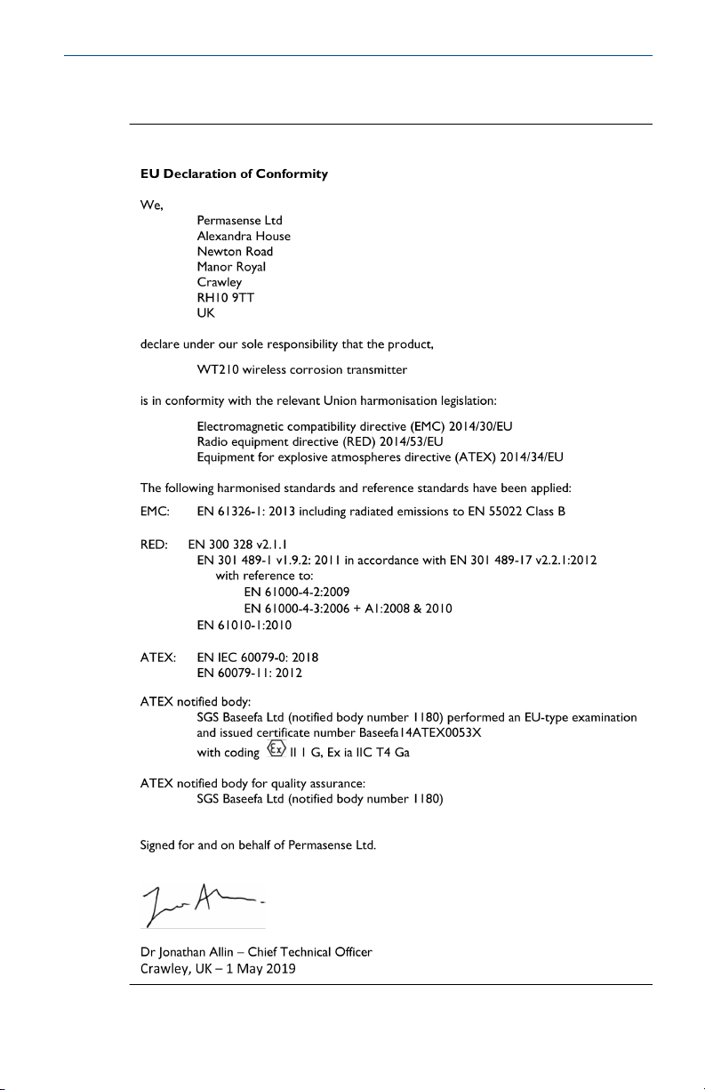
7.7 Declaration of Conformity
Figure 7-1: Declaration of Conformity
Quick Start Guide 21
Page 22

Quick Start Guide July 2019
7.8 China RoHS
22 Emerson.com/Rosemount
Page 23

July 2019 Quick Start Guide
Quick Start Guide 23
Page 24

*00825-0100-4210*
00825-0100-4210, Rev. AB
Quick Start Guide
July 2019
Global Headquarters
Emerson Automation Solutions
6021 Innovation Blvd.
Shakopee, MN 55379, USA
+1 800 999 9307 or +1 952 906 8888
+1 952 949 7001
RFQ.RMD-RCC@Emerson.com
Latin America Regional Office
Emerson Automation Solutions
1300 Concord Terrace, Suite 400
Sunrise, FL 33323, USA
+1 954 846 5030
+1 954 846 5121
RFQ.RMD-RCC@Emerson.com
Asia Pacific Regional Office
Emerson Automation Solutions
1 Pandan Crescent
Singapore 128461
+65 6777 8211
+65 6777 0947
Enquiries@AP.Emerson.com
North America Regional Office
Emerson Automation Solutions
8200 Market Blvd.
Chanhassen, MN 55317, USA
+1 800 999 9307 or +1 952 906 8888
+1 952 949 7001
RMT-NA.RCCRFQ@Emerson.com
Europe Regional Office
Emerson Automation Solutions Europe
GmbH
Neuhofstrasse 19a P.O. Box 1046
CH 6340 Baar
Switzerland
+41 (0) 41 768 6111
+41 (0) 41 768 6300
RFQ.RMD-RCC@Emerson.com
Middle East and Africa Regional Office
Emerson Automation Solutions
Emerson FZE P.O. Box 17033
Jebel Ali Free Zone - South 2
Dubai, United Arab Emirates
+971 4 8118100
+971 4 8865465
RFQ.RMTMEA@Emerson.com
Linkedin.com/company/Emerson-
Automation-Solutions
Twitter.com/Rosemount_News
Facebook.com/Rosemount
Youtube.com/user/
RosemountMeasurement
©
2019 Emerson. All rights reserved.
Emerson Terms and Conditions of Sale are
available upon request. The Emerson logo is a
trademark and service mark of Emerson Electric
Co. Rosemount is a mark of one of the Emerson
family of companies. All other marks are the
property of their respective owners.
 Loading...