

Page 1
Quick Start Guide
00825-0100-4004, Rev FG
August 2020
Rosemount™ 8800D Series Vortex Flow
Meter
Page 2

Quick Start Guide August 2020
Contents
About this guide...........................................................................................................................3
Return policy................................................................................................................................6
Emerson Flow customer service................................................................................................... 7
Pre-installation............................................................................................................................. 8
Basic installation.........................................................................................................................21
Basic configuration.....................................................................................................................40
Safety instrumented systems installation................................................................................... 49
Product certifications................................................................................................................. 50
2 Rosemount™ 8800D Series Vortex Flow Meter
Page 3
August 2020 Quick Start Guide
1 About this guide
This guide provides basic installation and configuration instructions for the
Rosemount™ 8800D Series Vortex Flow meters with single, dual, or quad
transmitters.
For more information on installation and configuration instructions,
diagnostics, maintenance, service, and troubleshooting for:
• Foundation Fieldbus devices consult 00809-0100-4772 Manual
• Non-MultiVariable meters and meters with the MTA option code for
HART and all Foundation Fieldbus devices, please consult
00809-0100-4004 Manual
For more information on installation and configuration instructions,
diagnostics, maintenance, service, and troubleshooting, for meters with the
MPA or MCA option code, please consult 00809-1100-4004 Manual.
For hazardous location installation, including Explosion-proof, Flameproof,
or Intrinsic Safety (I.S.), please consult 00825-VA00-0001 Approval
Document.
1.1 Hazard messages
This document uses the following criteria for hazard messages based on
ANSI standards Z535.6-2011 (R2017).
DANGER
Serious injury or death will occur if a hazardous situation is not avoided.
WARNING
Serious injury or death could occur if a hazardous situation is not avoided.
CAUTION
Minor or moderate injury will or could occur if a hazardous situation is not
avoided.
NOTICE
Data loss, property damage, hardware damage, or software damage can
occur if a situation is not avoided. There is no credible risk of physical injury.
Quick Start Guide 3
Page 4

Quick Start Guide August 2020
Physical access
NOTICE
Unauthorized personnel can potentially cause significant damage and/or
misconfiguration of end users' equipment. Protect against all intentional or
unintentional unauthorized use.
Physical security is an important part of any security program and
fundamental to protecting your system. Restrict physical access to protect
users' assets. This is true for all systems used within the facility.
1.2 Safety messages
WARNING
Explosion hazards. Failure to follow these instructions could cause an
explosion, resulting in death or serious injury.
• Verify the operating atmosphere of the transmitter is consistent with the
appropriate hazardous locations certifications.
• Installation of this transmitter in an explosive environment must be in
accordance with the appropriate local, national, and international
standards, codes, and practices. Review the approvals documents for
any restrictions associated with a safe installation.
• Do not remove transmitter covers or thermocouple (if equipped) in
explosive atmospheres when the circuit is live. Both transmitter covers
must be fully engaged to meet explosion-proof requirements.
• Before connecting a hand-held communicator in an explosive
atmosphere, make sure the instruments in the loop are installed in
accordance with intrinsically safe or non-incendive field wiring practices.
WARNING
Electrical shock hazard. Failure to follow this instruction could result in death
or serious injury. Avoid contact with the leads and terminals. High voltage
that may be present on leads can cause electrical shock.
4 Rosemount™ 8800D Series Vortex Flow Meter
Page 5

August 2020 Quick Start Guide
WARNING
General hazard. Failure to follow these instructions could result in death or
serious injury.
• This product is intended to be used as a flowmeter for liquid, gas, or
steam applications. Do not use for any other purpose.
• Make sure only qualified personnel perform the installation.
Quick Start Guide 5
Page 6

Quick Start Guide August 2020
2 Return policy
Emerson procedures must be followed when returning equipment. These
procedures ensure legal compliance with government transportation
agencies and help provide a safe working environment for Emerson
employees. Failure to follow Emerson procedures will result in your
equipment being refused delivery.
6 Rosemount™ 8800D Series Vortex Flow Meter
Page 7
August 2020 Quick Start Guide
3 Emerson Flow customer service
Email:
• Worldwide: flow.support@emerson.com
• Asia-Pacific: APflow.support@emerson.com
Telephone:
North and South America Europe and Middle East Asia Pacific
United States 800 522 6277 U.K. 0870 240
Canada +1 303 527
5200
Mexico +41 (0) 41
7686 111
Argentina +54 11 4837
7000
Brazil +55 15 3413
8000
Venezuela +58 26 1731
3446
The
Netherlands
France 0800 917 901 India 800 440 1468
Germany 0800 182
Italy 8008 77334 China +86 21 2892
Central &
Eastern
Europe
Russia/CIS +7 495 995
Egypt 0800 000
Oman 800 70101 Thailand 001 800 441
Qatar 431 0044 Malaysia 800 814 008
Kuwait 663 299 01
South Africa 800 991 390
Saudi Arabia 800 844 9564
UAE 800 0444
1978
+31 (0) 704
136 666
5347
+41 (0) 41
7686 111
9559
0015
0684
Australia 800 158 727
New Zealand 099 128 804
Pakistan 888 550 2682
9000
Japan +81 3 5769
6803
South Korea +82 2 3438
4600
Singapore +65 6 777
8211
6426
Quick Start Guide 7
Page 8

Quick Start Guide August 2020
4 Pre-installation
4.1 Planning
For a successful installation, consider each aspect of your application and the
meter you are installing.
4.1.1 Sizing
To determine the correct meter size for optimal flow meter performance:
• Determine the limits of measuring flow.
• Determine the process conditions so that they are within the stated
requirements for Reynolds number and velocity.
For sizing details, refer to the product reference manual.
Sizing calculations are required to select the proper flow meter size. These
calculations provide pressure loss, accuracy, and minimum and maximum
flow rate data to guide in proper selection. Vortex sizing software can be
found using the Selection and Sizing tool. The Selection and Sizing tool can
be accessed online or downloaded for offline use using this link:
www.Emerson.com/FlowSizing.
4.1.2 Wetted material selection
Ensure that the process fluid is compatible with the meter body wetted
materials when specifying the Rosemount 8800D. Corrosion will shorten the
life of the meter body. Consult recognized sources of corrosion data or
contact Emerson Flow Sales Representative for more information.
Note
If Positive Material Identification (PMI) is required, perform test on a
machined surface.
4.1.3 Orientation
The best orientation for the meter depends on the process fluid,
environmental factors, and any other nearby equipment.
Vertical installation
Vertical, upward, installation allows upward process liquid flow and is
generally preferred. Upward flow ensures that the meter body always
remains full and that any solids in the fluid are evenly distributed.
The meter can be mounted in the vertical down position when measuring
gas or steam flows. This type of application is strongly discouraged for liquid
flows, although it can be done with proper piping design.
8 Rosemount™ 8800D Series Vortex Flow Meter
Page 9
August 2020 Quick Start Guide
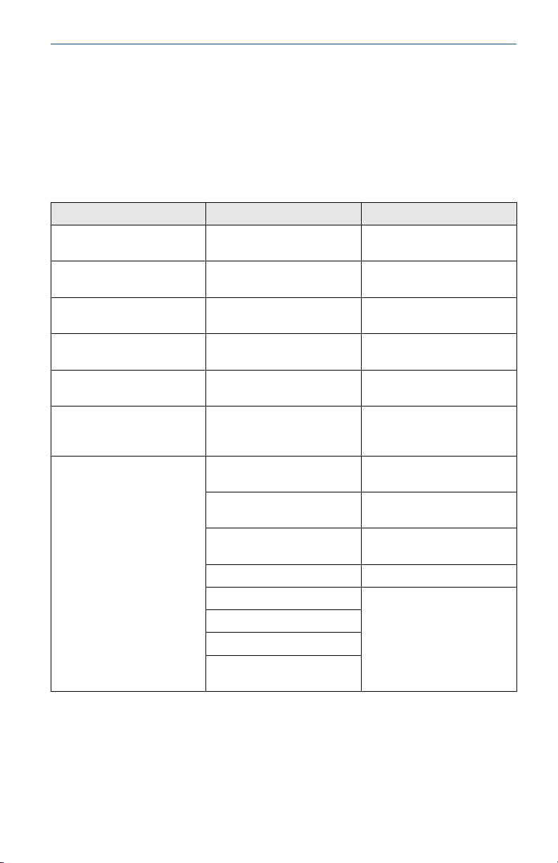
Figure 4-1: Vertical installation
A B
A. Liquid or gas flow
B. Gas flow
Note
To ensure the meter body remains full, avoid downward vertical liquid flows
where back pressure is inadequate.
Horizontal installation
For horizontal installation, the preferred orientation is to have the
electronics installed to the side of the pipe. In liquid applications, this helps
prevent any entrained air or solids from striking the shedder bar and
disrupting the shedding frequency. In gas or steam applications, this helps
prevent any entrained liquid (such as condensate) or solids do not strike the
shedder bar and disrupt the shedding frequency.
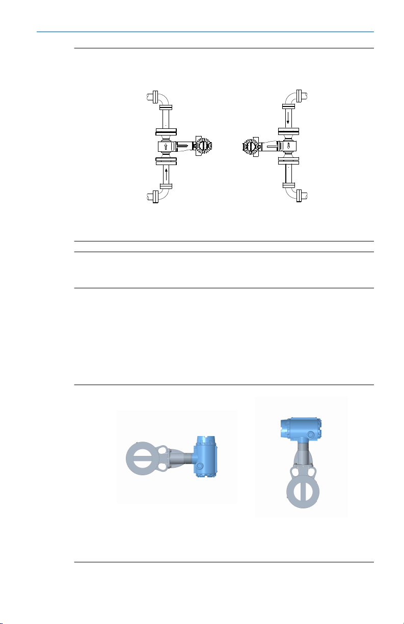
Figure 4-2: Horizontal installation
B
A
A. Preferred installation—meter body installed with electronics to side of
pipe
B. Acceptable installation—meter body installed with electronics above pipe
Quick Start Guide 9
Page 10
Quick Start Guide August 2020
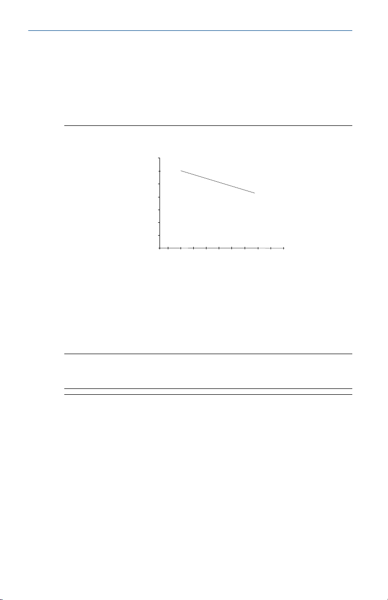
High-temperature installations
The maximum process temperature for integral electronics is dependent on
the ambient temperature where the meter is installed. The electronics must
not exceed 185 °F (85 °C).
Figure 4-3 shows combinations of ambient and process temperatures
needed to maintain a housing temperature of less than 185 °F (85 °C).
Figure 4-3: Ambient/Process temperature limits
200 (93)
180(82)
160 (71)
600 (316)
700 (371)
C
800 (427)
900 (482)
1000 (538)
A
140 (60)
120 (49)
100 (38)
80 (27)
60 (16)
0
100 (38)
200 (93)
300 (149)
400 (204)
500 (260)
B
A. Ambient temperature °F (°C)
B. Process temperature °F (°C)
C. 185 °F (85 °C) Housing temperature limit.
Note
The indicated limits are for horizontal pipe and vertical meter position, with
meter and pipe insulated with 3 in. (77 mm) of ceramic fiber insulation.
Install the meter body so the electronics are positioned to the side of the
pipe or below the pipe as shown in Figure 4-4. Insulation may also be
required around the pipe to maintain an electronics temperature below
185 °F (85 °C). See Figure 5-2 for special insulation considerations.
10 Rosemount™ 8800D Series Vortex Flow Meter
Page 11
August 2020 Quick Start Guide
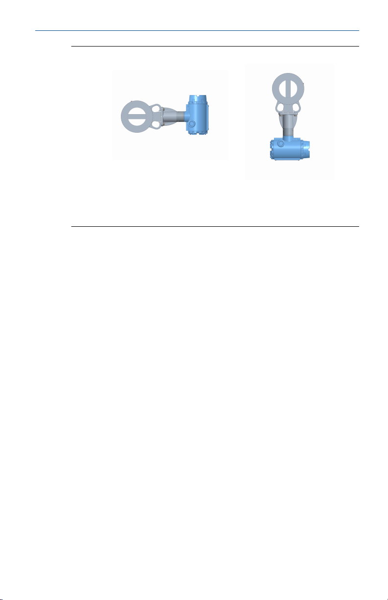
Figure 4-4: Examples of high-temperature installations
B
A
A. Preferred installation—The meter body installed with the electronics to
the side of the pipe.
B. Acceptable installation—The meter body installed with the electronics
below the pipe.
4.1.4 Location
Hazardous area
The transmitter has an explosion-proof housing and circuitry suitable for
intrinsically safe and non-incendive operation. Individual transmitters are
clearly marked with a tag indicating the certifications they carry. See Product
certifications.
Environmental considerations
Avoid excessive heat and vibration to ensure maximum flow meter life.
Typical problem areas include high-vibration lines with integrally mounted
electronics, warm-climate installations in direct sunlight, and outdoor
installations in cold climates.
Although the signal conditioning functions reduce susceptibility to
extraneous noise, some environments are more suitable than others. Avoid
placing the flow meter or its wiring close to devices that produce high
intensity electromagnetic and electrostatic fields. Such devices include
electric welding equipment, large electric motors and transformers, and
communication transmitters.
Upstream and downstream piping
The meter may be installed with a minimum of ten diameters (D) of straight
pipe length upstream and five diameters (D) of straight pipe length
downstream.
To achieve reference accuracy, straight pipe lengths of 35D upstream and
5D downstream are required. The value of the K-factor may shift up to 0.5%
when the upstream straight pipe length is between 10D and 35D. For
Quick Start Guide 11
Page 12
Quick Start Guide August 2020
optional K-factor corrections, see Rosemount™ 8800 Vortex Installation Effects
Technical Data Sheet.
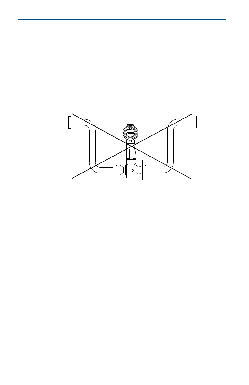
Steam piping
For steam applications, avoid installations such as the one shown in the
following figure. Such installations may cause a water-hammer condition at
start-up due to trapped condensation. The high force from the water
hammer can stress the sensing mechanism and cause permanent damage to
the sensor.
Figure 4-5: Wrong steam pipe installation
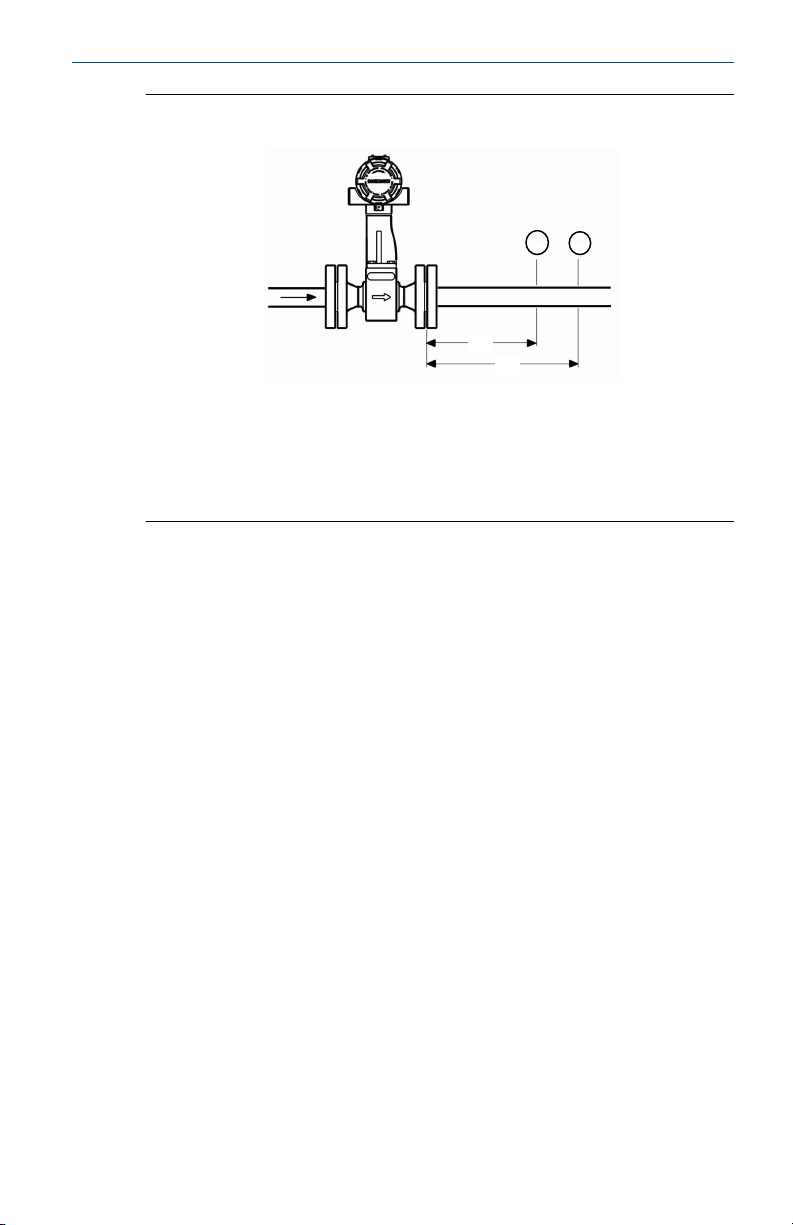
Pressure and temperature transmitter location
When using pressure and temperature transmitters in conjunction with the
vortex flow meter for compensated mass flows, install the transmitter(s)
downstream of the vortex flow meter.
12 Rosemount™ 8800D Series Vortex Flow Meter
Page 13
August 2020 Quick Start Guide
Figure 4-6: Pressure and temperature transmitter location
C
A
B
D
A. Pressure transmitter
B. Four straight pipe diameters downstream
C. Temperature transmitter
D. Six straight pipe diameters downstream
4.1.5 Power supply (HART)
Analog 4–20 mA Power supply
External power supply required. Each transmitter operates on 10.8 VDC to
42 VDC terminal voltage. See Figure 4-7.
Power consumption
One watt maximum per transmitter.
Quick Start Guide 13
Page 14
5വ
9SV
Quick Start Guide August 2020
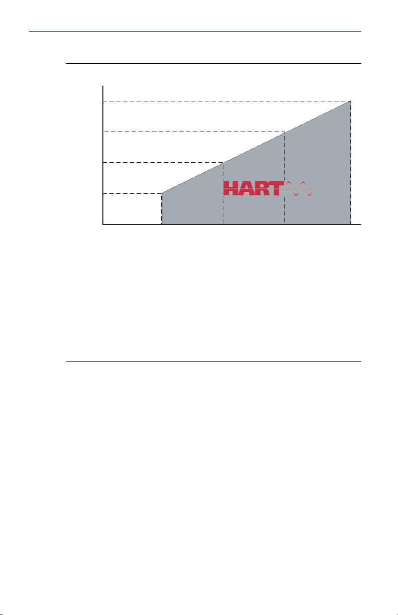
HART communication
Figure 4-7: HART communication voltage/resistance requirement
Maximum loop resistance is determined by the voltage level of the external
power supply, as described in the graph.
Note that HART Communication requires a minimum loop resistance of
250 ohms up to a maximum of 1100 ohms.
R(Ω)
V
ps
Load resistor value.
Minimum power supply voltage required
R(Ω)max = 41.7 (Vps – 10.8 V).
Additional wiring information
• The DC power supply should provide power with less than two percent
ripple. The total resistance load is the sum of the resistance of the signal
wiring and the load resistance of the controller, indicator, and related
pieces. Note that the resistance of intrinsic safety barriers, if used, must
be included.
• If a Smart Wireless THUM™ Adapter is being used with the flow meter to
exchange information via IEC 62591 (WirelessHART® Protocol)
technology, a minimum loop resistance of 250 ohms is required. In
addition, a minimum power supply voltage (Vps) of 19.3 volts will be
required to output 24 mA.
• If a single power supply is used to power more than one transmitter, the
power supply used and circuitry common to the transmitters should not
have more than 20 ohms of impedance at 1200 Hz. See Table 4-1.
14 Rosemount™ 8800D Series Vortex Flow Meter
Page 15

August 2020 Quick Start Guide
Table 4-1: Resistance based on wire gauge
Gauge number Ohms per 1,000 ft (305 m) at 68 °F
14 AWG (2 mm2) 2.5
16 AWG (1 mm2) 4.0
18 AWG (0.8mm2) 6.4
20 AWG (0.5 mm2) 10
22 AWG (0.3 mm2) 16
24 AWG (0.2 mm2) 26
4.1.6 Power supply (FOUNDATION fieldbus)
The flowmeter requires 9-32 Vdc at the power terminals. Each fieldbus
power supply requires a power conditioner to decouple the power supply
output from the fieldbus wiring segment.
4.2 Commissioning
For proper configuration and operation, commission the meter before
putting it into operation. Bench commissioning also enables you to check
hardware settings, test the flowmeter electronics, verify flowmeter
configuration data, and check output variables. Any problems can be
corrected—or configuration settings changed—before going out into the
installation environment. To commission on the bench, connect a
configuration device to the signal loop in accordance the device
instructions.
(20 °C) equivalent
4.2.1 HART jumper configuration
Two jumpers on the transmitter specify the alarm and security modes. Set
these jumpers during the commissioning stage to avoid exposing the
electronics to the plant environment. The two jumpers can be found on the
electronics board stack or on the LCD meter.
Alarm
Security
Quick Start Guide 15
As part of normal operations, the transmitter continuously runs
a self-diagnostic routine. If the routine detects an internal failure
in the electronics, flow meter output is driven to a low or high
alarm level, depending on the position of the failure mode
jumper. The factory sets the jumper according to the
Configuration Data Sheet, if applicable, or HI by default.
You can protect the configuration data with the security lockout
jumper. With the security lockout jumper ON, any configuration
changes attempted on the electronics are disallowed. You can
still access and review any of the operating parameters and scroll
Page 16
Quick Start Guide August 2020
through the available parameters, but no changes can be made.
The factory sets the jumper according to the Configuration Data
Sheet, if applicable, or OFF by default.
Note
If you will be changing configuration variables frequently, it may
be useful to leave the security lockout jumper in the OFF position
to avoid exposing the flow meter electronics to the plant
environment.
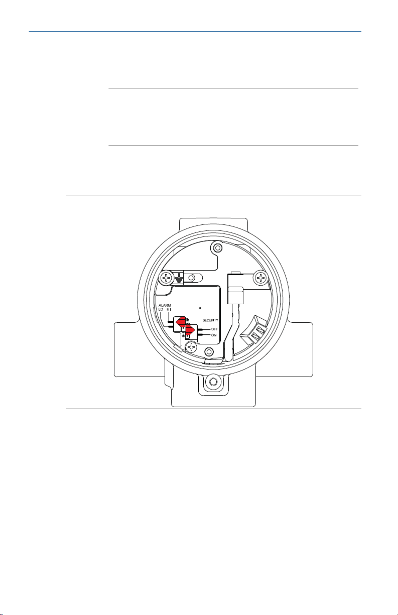
To access the jumpers, remove the transmitter electronics housing or the
LCD cover (if equipped) opposite of the terminal blocks, See Figure 4-8 and
Figure 4-9.
Figure 4-8: Alarm and security jumpers (no LCD option)
VORTEX
4-20mA
HART
TEST FREQ
IN
TP1
16 Rosemount™ 8800D Series Vortex Flow Meter
Page 17

August 2020 Quick Start Guide
Figure 4-9: LCD indicator alarm and security jumpers (with LCD option)
HI LO
HI LO
ALARM
ALARM
FLOW
SECURITY
SECURITY
ON OFF
ON OFF
Failure mode vs. saturation output values
The failure mode alarm output levels differ from the output values that
occur when the operating flow is outside the range points. When the
operating flow is outside the range points, the analog output continues to
track the operating flow until reaching the saturation value listed below; the
output does not exceed the listed saturation value regardless of the
operating flow. For example, with standard alarm and saturation levels and
flows outside the 4–20 mA range points, the output saturates at 3.9 mA or
20.8 mA. When the transmitter diagnostics detect a failure, the analog
output is set to a specific alarm value that differs from the saturation value
to allow for proper troubleshooting. The saturation and alarm levels are
software selectable between Rosemount Standard and NAMUR levels.
Table 4-2: Analog output: standard alarm values vs. saturation values
Level 4–20 mA saturation value 4–20 mA alarm value
Low 3.9 mA ≤ 3.75 mA
High 20.8 mA ≥ 21.75 mA
Table 4-3: Analog output: NAMUR-compliant alarm values vs. saturation
values
Level 4–20 mA saturation value 4–20 mA alarm value
Low 3.8 mA ≤ 3.6 mA
High 20.5 mA ≥ 22.6 mA
Quick Start Guide 17
Page 18

Quick Start Guide August 2020
4.2.2 FOUNDATION fieldbus jumper configuration
Two jumpers on the transmitter specify the simulation and security modes.
Set these jumpers during the commissioning stage to avoid exposing the
electronics to the plant environment. The two jumpers can be found on the
electronics board stack or on the LCD meter.
Simulate
The simulate enable jumper is used in conjunction with the
Analog Input (AI) function block simulation. The jumper is also
used as a lock-out feature for the AI function block. To enable
the simulate enable feature, the jumper must transition from
OFF to ON after power is applied to the transmitter, preventing
the transmitter from being accidentally left in simulator mode.
The factory sets the jumper to OFF by default.
Security
You can protect the configuration data with the security lockout
jumper. With the security lockout jumper ON, any configuration
changes attempted on the electronics are disallowed. You can
still access and review any of the operating parameters and
scroll through the available parameters, but no changes can be
made. The factory sets the jumper to OFF by default.
To access the jumpers, remove the transmitter LCD cover (if equipped) or
the electronics housing cover opposite of the terminal blocks, See Figure
4-10 and Figure 4-11.
18 Rosemount™ 8800D Series Vortex Flow Meter
Page 19

Installation
May 2019
The hardware jumpers on the flowmeter enable you to set the fieldbus simulate enable and
transmitter security (see Figure 3-19). To access the jumpers, remove the electronics
housing cover from the end of the flowmeter. If the flowmeter does not include an LCD
display, the jumpers are accessible by removing the cover on the electronics side. If the
flowmeter includes an LCD display option, the fieldbus simulate enable and security
jumpers are found on the face of the LCD display (see Figure 3-20).
Note
If you will be changing configuration variables frequently, leave the security lockout jumper
in the OFF position to avoid exposing the flowmeter electronics to the plant environment.
Set jumpers during the commissioning stage to avoid exposing the electronics to the plant
environment.
Figure 3-19. Fieldbus Simulate Enable and Transmitter Security Jumpers
August 2020 Quick Start Guide
Figure 4-10: Alarm and security jumpers (no LCD option)
Quick Start Guide 19
Page 20

Reference Manual
00809-0100-4772, Rev FB
After you configure the transmitter, you may want to protect the configuration data from
unwarranted changes. Each transmitter is equipped with a security jumper that can be
positioned ON to prevent the accidental or deliberate change of configuration data. The
jumper is located on the front side of the electronics module and is labeled SECURITY (see
Figure 3-19).
If your electronics are equipped with the LCD display (Option M5), the fieldbus simulate
enable and transmitter security jumpers are located on the face of the indicator as shown in
Figure 3-20.
Figure 3-20. LCD Display Fieldbus Simulate Enable and Transmitter Security Jumpers
SIMULATE ENABLE
SECURITY
ON
OFF
OFF
ON
Quick Start Guide August 2020
Figure 4-11: LCD indicator alarm and security jumpers (with LCD option)
4.2.3 Calibration
The flow meter is wet-calibrated at the factory and needs no further
calibration during installation. The calibration factor (K-factor) is indicated
on each meter body and is entered into the electronics. Verification can be
accomplished with a configuration device.
20 Rosemount™ 8800D Series Vortex Flow Meter
Page 21

August 2020 Quick Start Guide
5 Basic installation
5.1 Handling
Handle all parts carefully to prevent damage. Whenever possible, transport
the system to the installation site in the original shipping containers. Keep
the shipping plugs in the conduit connections until you are ready to connect
and seal them.
NOTICE
To avoid damage to the meter, do not lift the flow meter by the transmitter.
Lift the meter by the meter body. Lifting supports can be tied around the
meter body as shown.
Figure 5-1: Lifting supports
5.2 Flow direction
Mount the meter body so the FORWARD end of the flow arrow, shown on
the meter body, points in the direction of the flow in the pipe.
5.3
Quick Start Guide 21
Gaskets
The flow meter requires gaskets supplied by the user. Be sure to select
gasket material that is compatible with the process fluid and pressure
ratings of the specific installation.
Note
Ensure the inside diameter of the gasket is larger than the inside diameter of
the flow meter and adjacent piping. If gasket material extends into the flow
stream, it will disturb the flow and cause inaccurate measurements.
Page 22

Quick Start Guide August 2020
5.4 Insulation
Insulation should extend to the end of the bolt on the bottom of the meter
body and should leave at least 1-in. (25 mm) of clearance around the
electronics bracket. The electronics bracket and electronics housing should
not be insulated. See #unique_12/unique_12_Connect_42_Insulation.
Figure 5-2: Insulation best practice to prevent electronics overheating
CAUTION
To avoid damage to electronics in high temperature installations, and for
both integral and remote electronics, only insulate the meter body as
shown, do not insulate the area around the electronics.
5.5
22 Rosemount™ 8800D Series Vortex Flow Meter
Flanged-style flow meter mounting
Most vortex flow meters use a flanged-style process connection. Physical
mounting of a flanged-style flow meter is similar to installing a typical
section of pipe. Conventional tools, equipment, and accessories (such as
bolts and gaskets) are required. Tighten the nuts following the sequence
shown in Figure 5-4.
Note
The required bolt load for sealing the gasket joint is affected by several
factors, including operating pressure and gasket material, width, and
condition. A number of factors also affect the actual bolt load resulting from
a measured torque, including condition of bolt threads, friction between the
nut head and the flange, and parallelism of the flanges. Due to these
Page 23

August 2020 Quick Start Guide
application-dependent factors, the required torque for each application may
be different. Follow the guidelines outlined in ASME PCC-1 for proper bolt
tightening. Make sure the flow meter is centered between flanges of the
same nominal size as the flow meter.
Figure 5-3: Flanged-style flow meter installation
A. Installation studs and nuts (supplied by customer)
B. Gaskets (supplied by customer)
C. Flow
Quick Start Guide 23
Page 24

Quick Start Guide August 2020
Figure 5-4: Flange bolt torquing sequence
Note
See the product reference manual for instructions on retrofitting 8800D to
8800A installations.
5.6
24 Rosemount™ 8800D Series Vortex Flow Meter
Wafer-style flow meter alignment and mounting
Center the wafer-style meter body inside diameter with respect to the inside
diameter of the adjoining upstream and downstream piping. This will ensure
the flow meter achieves its specified accuracy. Alignment rings are provided
with each wafer-style meter body for centering purposes. Follow these steps
to align the meter body for installation. Refer to Figure 5-5.
1. Place the alignment rings over each end of the meter body.
2. Insert the studs for the bottom side of the meter body between the
pipe flanges.
3. Place the meter body (with alignment rings) between the flanges.
• Make sure the alignment rings are properly placed onto the
studs.
• Align the studs with the markings on the ring that correspond to
the flange you are using.
• If a spacer is used, see the product reference manual.
Page 25

August 2020 Quick Start Guide
Note
Be sure to align the flow meter so the electronics are accessible, the
conduits drain, and the flow meter is not subject to direct heat.
4. Place the remaining studs between the pipe flanges.
5. Tighten the nuts in the sequence shown in Figure 5-4.
6. Check for leaks at the flanges after tightening the flange bolts.
Note
The required bolt load for sealing the gasket joint is affected by
several factors, including operating pressure and gasket material,
width, and condition. A number of factors also affect the actual bolt
load resulting from a measured torque, including condition of bolt
threads, friction between the nut head and the flange, and
parallelism of the flanges. Due to these application-dependent
factors, the required torque for each application may be different.
Follow the guidelines outlined in ASME PCC-1 for proper bolt
tightening. Make sure the flow meter is centered between flanges of
the same nominal size as the flow meter.
Figure 5-5: Wafer-style flow meter installation with alignment
rings
B
B
A
D
C
A. Installation studs and nuts (supplied by customer)
B. Alignment rings
C. Spacer (for Rosemount 8800D to maintain Rosemount 8800A
dimensions)
D. Flow
5.6.1 Stud bolts for wafer-style flow meters
The following tables list the recommended minimum stud bolt lengths for
wafer-style meter body size and different flange ratings.
Quick Start Guide 25
Page 26

Quick Start Guide August 2020
Table 5-1: Stud bolt length for wafer-style flow meters with ASME B16.5
flanges
Line size Minimum recommended stud bolt lengths (in inches) for
½-inch 6.00 6.25 6.25
1-inch 6.25 7.00 7.50
1½-inch 7.25 8.50 9.00
2-inch 8.50 8.75 9.50
3-inch 9.00 10.00 10.50
4-inch 9.50 10.75 12.25
6-inch 10.75 11.50 14.00
8-inch 12.75 14.50 16.75
each flange rating
Class 150 Class 300 Class 600
Table 5-2: Stud bolt length for wafer-style flow meters with EN 1092
flanges
Line size Minimum recommended stud bolt lengths (in mm) for each
DN 15 160 160 170 170
DN 25 160 160 200 200
DN 40 200 200 230 230
DN 50 220 220 250 270
DN 80 230 230 260 280
DN 100 240 260 290 310
DN 150 270 300 330 350
DN 200 320 360 400 420
flange rating
PN 16 PN 40 PN 63 PN 100
Line size Minimum recommended stud bolt lengths (in mm) for
15mm 150 155 185
25mm 175 175 190
40mm 195 195 225
26 Rosemount™ 8800D Series Vortex Flow Meter
each flange rating
JIS 10k JIS 16k and 20k JIS 40k
Page 27

August 2020 Quick Start Guide
Line size Minimum recommended stud bolt lengths (in mm) for
50mm 210 215 230
80mm 220 245 265
100mm 235 260 295
150mm 270 290 355
200mm 310 335 410
each flange rating
JIS 10k JIS 16k and 20k JIS 40k
5.7 Cable glands
If you are using cable glands instead of conduit, follow the cable gland
manufacturer’s instructions for preparation and make the connections in a
conventional manner in accordance with local or plant electrical codes. Be
sure to properly seal unused ports to prevent moisture or other
contamination from entering the terminal block compartment of the
electronics housing.
5.8 Flow meter grounding
Grounding is not required in typical vortex applications; however, a proper
ground will eliminate possible noise pickup by the electronics. Grounding
straps may be used to ensure that the meter is grounded to the process
piping. If you are using the transient protection option (T1), grounding
straps are required to provide a proper low impedance ground.
Note
Properly ground flow meter body and transmitter per the local code.
To use grounding straps, secure one end of the grounding strap to the bolt
extending from the side of the meter body and attach the other end of each
grounding strap to a suitable ground. See Figure 5-6.
Quick Start Guide 27
Page 28

Quick Start Guide August 2020
Figure 5-6: Grounding connections
A. Internal ground connection
B. External ground assembly
5.9 Grounding the transmitter case
The transmitter case should always be grounded in accordance with national
and local electrical codes. The most effective transmitter case grounding
method is direct connection to earth ground with minimal impedance.
Methods for grounding the transmitter case include:
Internal
Ground
Connection
External
Ground
Assembly
Note
Grounding the transmitter case using the threaded conduit connection may
not provide a sufficient ground. The transient protection terminal block
(Option Code T1) does not provide transient protection unless the
28 Rosemount™ 8800D Series Vortex Flow Meter
The Internal Ground Connection screw is inside the FIELD
TERMINALS side of the electronics housing. This screw is
identified by a ground symbol ( ), and is standard on all
Rosemount 8800D transmitters.
This assembly is located on the outside of the electronics
housing and is included with the optional transient
protection terminal block (Option Code T1). The External
Ground Assembly can also be ordered with the
transmitter (Option Code V5) and is automatically
included with certain hazardous area approvals. See
Figure 5-6 for the location of the external ground
assembly.
Page 29

August 2020 Quick Start Guide
transmitter case is properly grounded. For transient terminal block
grounding, see the Reference Manual. Use the above guidelines to ground
the transmitter case. Do not run the transient protection ground wire with
signal wiring as the ground wire may carry excessive electric current if a
lightning strike occurs.
5.10 Conduit installation
Prevent condensation in any conduit from flowing into the housing by
mounting the flowmeter at a high point in the conduit run. If the flowmeter
is mounted at a low point in the conduit run, the terminal compartment
could fill with fluid.
If the conduit originates above the flowmeter, route conduit below the
flowmeter before entry. In some cases a drain seal may need to be installed.
Figure 5-7: Proper conduit installation
A A
A. Conduit line
5.11
Quick Start Guide 29
Wiring
The signal terminals are located in a compartment of the electronics housing
separate from the flow meter electronics. Connections for a configuration
tool and an electric current test connection are above the signal terminals.
Note
A power disconnect is required to remove power from the transmitter for
maintenance, removal, and replacement.
Common wiring practices
Twisted pairs are required to minimize noise pickup in the 4–20 mA signal
and digital communication signal. For high EMI/RFI environments, shielded
signal wire is required and recommended in all other installations. To ensure
Page 30

A
Quick Start Guide August 2020
communication, wiring should be 24 AWG (0.205 mm²) or larger, and not
exceed 5,000 ft (1500 m).
5.11.1 Analog output
The flow meter provides a 4–20 mA dc isolated electric current output,
linear with the flow rate. To make connections, remove the FIELD
TERMINALS side cover of the electronics housing. All power to the
electronics is supplied over the 4–20 mA signal wiring. Connect the wires as
shown.
Note
Twisted pairs are required to minimize noise pickup in the 4–20 mA signal
and digital communication signal. For high EMI/RFI environments, shielded
signal wire is required and recommended in all other installations. To ensure
communication, wiring should be 24 AWG or larger, and not exceed 5,000 ft
(1500 m).
Figure 5-8: 4–20 mA wiring
A. Power supply. See Power supply (HART).
5.11.2 FOUNDATION fieldbus wiring
Each fieldbus power supply requires a power conditioner to decouple the
power supply output from the fieldbus wiring segment.
All power to the transmitter is supplied over the segment wiring. Use
shielded, twisted pair for best results. For new installations or to get
maximum performance, twisted pair cable designed especially for fieldbus
should be used. Table 5-3 lists the cable characteristics and ideal
specifications.
30 Rosemount™ 8800D Series Vortex Flow Meter
Page 31

August 2020 Quick Start Guide
Table 5-3: Ideal cable specifications for fieldbus wiring
Characteristic Ideal specification
Impedance 100 Ohms ±20% at 31.25 kHz
Wire size 18 AWG (0.8 mm2)
Shield coverage 90%
Attenuation 3 db/km
Capacitive unbalance 2 nF/km
Note
The number of devices on a fieldbus segment is limited by the power supply
voltage, the resistance of the cable, and the amount of current drawn by
each device.
Transmitter wiring connection
To make the transmitter wiring connection, remove the FIELD TERMINALS
end cover on the electronics housing. Connect the power leads to the
positive (+) and negative (–) terminals. The power terminals are polarity
insensitive: the polarity of the DC power leads does not matter when
connecting to the power terminals. When wiring to screw terminals,
crimped lugs are recommended. Tighten the terminals to ensure adequate
contact. No additional power wiring is required.
Quick Start Guide 31
Page 32

Quick Start Guide August 2020
Figure 5-9:
H
5.12
A
I
FOU DATION
Configuration
J
Tool
G
F
E
D
C*
D
A. Integrated power conditioner and filter
B. The power supply, filter, first terminator, and configuration tool are
typically located in the control room.
C. Devices 1 through 16 (Intrinsically safe installations may allow fewer
devices per I.S. barrier).
D. Spur
E. Trunk.
F. Fieldbus segment
G. Terminators
H. 6234 ft (1900 m) max (depending upon cable characteristics)
I. Power supply
J. Fieldbus configuration tool
Remote installation
If a remote electronics option (Rxx or Axx) was ordered, the flow meter
assembly will be shipped in two parts:
• The meter body with an adapter installed in the support tube and an
interconnecting coaxial cable attached to it.
• The electronics housing installed on a mounting bracket.
If an armored remote electronics option (Axx) was ordered, follow the same
instructions as for the standard remote cable connection with the exception
that the cable may not need to be run through conduit. Armored includes
the glands. Information on remote installation can be found in Cable
connections.
5.12.1 Mounting
Mount the meter body in the process flow line as described earlier in this
section. Mount the bracket and electronics housing in the desired location.
32 Rosemount™ 8800D Series Vortex Flow Meter
Page 33

August 2020 Quick Start Guide
The housing can be repositioned on the bracket to facilitate field wiring and
conduit routing.
5.12.2 Cable connections
Complete these steps for connecting the loose end of the coaxial cable to
the electronics housing. If connecting/disconnecting the meter adapter to
the meter body, refer to the product reference manual.
Figure 5-10: Remote installation
A
B
C
D
E
F
P
G
O
H
N
J
K
I
M
L
A. ½ NPT conduit adapter or cable gland (supplied by customer)
B. Coaxial cable
C. Meter adapter
D. Union
E. Washer
F. Nut
G. Sensor cable nut
H. Support tube
I. Meter body
J. Electronics housing
K. Coaxial cable SMA nut
L. ½ NPT conduit adapter or cable gland (supplied by customer)
M. Housing adapter screws
N. Housing adapter
O. Housing base screw
P. Ground connection
Quick Start Guide 33
Page 34

Quick Start Guide August 2020
CAUTION
To prevent moisture from entering the coaxial cable connections, install the
interconnecting coaxial cable in a single dedicated conduit run or use sealed
cable glands at both ends of the cable.
In remote mount configurations when ordered with a hazardous area option
code, the remote sensor cable and the interconnecting thermocouple cable
(MTA or MCA option) are protected by separate intrinsic safety circuits, and
must be segregated from each other, other intrinsically safe circuits, and
non-intrinsically safe circuits per local and national wiring code.
CAUTION
The coaxial remote cable cannot be field terminated or cut to length. Coil
any extra coaxial cable with no less than a 2-in. (51 mm) radius.
1. If you plan to run the coaxial cable in conduit, carefully cut the
conduit to the desired length to provide for proper assembly at the
housing. A junction box may be placed in the conduit run to provide a
space for extra coaxial cable length.
2. Slide the conduit adapter or cable gland over the loose end of the
coaxial cable and fasten it to the adapter on the meter body support
tube.
3. If using conduit, route the coaxial cable through the conduit.
4. Place a conduit adapter or cable gland over the end of the coaxial
cable.
5. Remove the housing adapter from the electronics housing.
6. Slide the housing adapter over the coaxial cable.
7. Remove one of the four housing base screws.
8. Attach the coaxial cable ground wire to the housing via the housing
base ground screw.
9. Attach and hand tighten the coaxial cable SMA nut to the electronics
housing to 7 in-lbs (0.8 N-m).
34 Rosemount™ 8800D Series Vortex Flow Meter
Page 35

August 2020 Quick Start Guide
Figure 5-11: Attaching and tightening SMA nut
A
B
A. SMA nut
B. Hand tighten
Note
Do not over-tighten the coaxial cable nut to the electronics housing.
10. Align the housing adapter with the housing and attach with two
screws.
11. Tighten the conduit adapter or cable gland to the housing adapter.
5.12.3 Housing rotation
The entire electronics housing may be rotated in 90° increments for easy
viewing. Use the following steps to change the housing orientation,
1. Loosen the three housing rotation set screws at the base of the
electronics housing with a 5/32” hex wrench by turning the screws
clockwise (inward) until they clear the support tube.
2. Slowly pull the electronics housing out of the support tube.
CAUTION
Do not pull the housing more than 1.5 in. (40 mm) from the top of
the support tube until the sensor cable is disconnected. Damage to
the sensor may occur if this sensor cable is stressed.
3. Unscrew the sensor cable from the housing with a 5/16” open end
wrench.
4. Rotate the housing to the desired orientation.
5. Hold it in this orientation while you screw the sensor cable onto the
base of the housing.
Quick Start Guide 35
Page 36

Quick Start Guide August 2020
CAUTION
Do not rotate the housing while the sensor cable is attached to the
base of the housing. This will stress the cable and may damage the
sensor.
6. Place the electronics housing into the top of the support tube.
7. Use a hex wrench to turn the three housing rotation screws counterclockwise (outward) to engage the support tube.
5.12.4 Specifications and requirements for remote sensor cable
If using a Rosemount remote sensor cable, observe these specifications and
requirements.
• The remote sensor cable is a proprietary design tri-axial cable
• It is considered a low voltage signal cable
• It is rated for and/or part of intrinsically safe installations
• Non armored version is designed to be run through metal conduit
• Cable is water resistant, but not submersible. As a best practice,
exposure to moisture should be avoided if possible
• Rated operating temperature is –58°F to +392°F (–50°C to +200°C)
• Flame Resistant in accordance with IEC 60332-3
• Non-armored and armored version minimum bend diameter is 8 inches
(203 mm)
• Nominal O.D. of the non-armored version is 0.160 inches (4 mm)
• Nominal O.D. of the armored version is 0.282 inches (7.1 mm)
36 Rosemount™ 8800D Series Vortex Flow Meter
Page 37

August 2020 Quick Start Guide
Figure 5-12: Non-armored cable
A. Transmitter end
B. Sensor end
C. Minimum bend diameter
D. Nominal O.D.
Figure 5-13: Armored cable
A. Transmitter end
B. Sensor end
C. Minimum bend diameter
5.12.5 Quad transmitter numbering and orientation
When quad vortex flow meters are ordered, for configuration purposes, the
transmitters are identified as Transmitter 1, Transmitter 2, Transmitter 3,
and Transmitter 4. The transmitter and meter body nameplate of a Quad
Vortex flow meter can be used to identify and verify the transmitter number.
See Figure 5-14 for Quad transmitter orientation and nameplate locations.
Quick Start Guide 37
Page 38

Quick Start Guide August 2020
See Figure 4-14 and 4-15 for Quad transmitter and meter body nameplate
number location.
Figure 5-14: Quad transmitter numbering
A. Transmitter 1 transmitter nameplate
B. Transmitter 1 meter body nameplate
C. Transmitter 2 transmitter nameplate
D. Transmitter 2 meter body nameplate
E. Transmitter 3 transmitter nameplate
F. Transmitter 3 meter body nameplate
G. Transmitter 4 transmitter nameplate
H. Transmitter 4 meter body nameplate
38 Rosemount™ 8800D Series Vortex Flow Meter
Page 39

August 2020 Quick Start Guide
Figure 5-15: Quad transmitter nameplate
Figure 5-16: Quad meter body nameplate
Quick Start Guide 39
Page 40

Quick Start Guide August 2020
6 Basic configuration
The transmitter must be configured for certain basic variables in order to be
operational. In most cases, all of these variables are pre-configured at the
factory. Configuration may be required if your transmitter is not configured
or if the configuration variables need revision. The basic setup section
includes parameters typically required for basic operation.
Note
ProLink III paths are only applicable to HART devices. For more information
on Fieldbus devices, refer to the 8800D product manual for Fieldbus
protocol (00809-0100-4772).
6.1 Process variables
Process variables define the flow meter output. When commissioning a flow
meter, review each process variable, its function and output, and take
corrective action if necessary before using the flow meter in a process
application.
6.1.1 Primary variable mapping
Allows the user to select which variables the transmitter will output.
ProLink III Device Tools → Configuration → Communications
Note
The Primary Variable is also the Analog Output variable.
This can be either Process Temperature (MTA or MCA option only) or Flow.
Flow variables are available as Corrected Volume Flow, Mass Flow, Velocity
Flow, or Volume Flow. When bench commissioning, the flow values for each
variable should be zero and the temperature value should be the ambient
temperature.
If the units for the flow or temperature variables are not correct, refer to
Process variable units. Use the Process Variable Units function to select the
units for your application.
(HART)
6.1.2 Percent of range
ProLink III Device Tools → Configuration → Outputs → Analog
The primary variable as a percentage of range provides a gauge as to where
the measured flow rate of the meter is within the configured range of the
40 Rosemount™ 8800D Series Vortex Flow Meter
Output
Page 41

August 2020 Quick Start Guide
meter. For example, the range may be defined as 0 gal/min to 20 gal/min. If
the measured flow rate is 10 gal/min, the percent of range is 50 percent.
6.1.3 Analog output
ProLink III Device Tools → Configuration → Outputs → Analog
The analog output variable provides the analog value for the primary
variable. The analog output refers to the industry standard output in the 4–
20 mA range. Check the analog output value against the actual loop reading
given by a multi-meter. If it does not match, a 4–20 mA, trim is required.
6.1.4 Process variable units
ProLink III Device Tools → Configuration → Process
Allows for the viewing and configuration of Process Variable Units such as
Volume, Velocity, Mass Flow, Electronics Temperature, Process Density, and
Corrected Volume units, including corrected volume Special Units
configuration.
Volume flow
Allows the user to view the volumetric flow rate value.
Volume flow units
Allows the user to select the volumetric flow units from the available list.
Table 6-1: Volume flow units
gallons per second gallons per minute gallons per hour
gallons per day cubic feet per second cubic feet per minute
cubic feet per hour cubic feet per day barrels per second
barrels per minute barrels per hour barrels per day
imperial gallons per
second
imperial gallons per day liters per second liters per minute
liters per hour liters per day cubic meters per second
cubic meters per minute cubic meters per hour cubic meters per day
mega cubic meters per
day
Output
Measurement → (select type)
imperial gallons per
minute
special units
imperial gallons per hour
Quick Start Guide 41
Page 42

Quick Start Guide August 2020
Corrected volumetric flow units
Allows the user to select the corrected volumetric flow units from the
available list.
Table 6-2: Corrected volume flow units
gallons per second gallons per minute gallons per hour
gallons per day cubic feet per second standard cubic feet per
standard cubic feet per
hour
barrels per minute barrels per hour barrels per day
imperial gallons per
second
imperial gallons per day liters per second liters per minute
liters per hour liters per day normal cubic meters per
normal cubic meters per
hour
cubic meters per minute cubic meters per hour cubic meters per day
special units
cubic feet per day barrels per second
imperial gallons per
minute
normal cubic meters per
day
minute
imperial gallons per hour
minute
cubic meters per second
Note
When measuring corrected volumetric flow, a base density and process
density must be provided.
Mass flow
Allows the user to view the mass flow rate values and units.
Mass flow units
Allows the user to select the mass flow units from the available list. (1 STon =
2000 lb; 1 MetTon = 1000 kg)
Table 6-3: Mass flow units
grams per hour grams per minute grams per second
kilograms per day kilograms per hour kilograms per minute
kilograms per second pounds per minute pounds per hour
pounds per day special units short tons per day
short tons per hour short tons per minute pounds per second
tons (metric) per day tons (metric) per hour tons (metric) per minute
42 Rosemount™ 8800D Series Vortex Flow Meter
Page 43

August 2020 Quick Start Guide
Note
If you select a Mass Flow Units option, you must enter process density in
your configuration.
Velocity flow
Allows the user to view the velocity flow rate value and units.
Velocity flow units
Allows the user to select the Velocity Flow Units from the available list.
• feet per second
• meters per second
Velocity measurement base
Determines if the velocity measurement is based on the mating pipe ID or
the meter body ID. This is important for Reducer™ Vortex Applications.
6.2 Tag
ProLink III Device Tools → Configuration → Informational
Parameters → Transmitter
The quickest way to identify and distinguish between flow meters. Flow
meters can be tagged according to the requirements of your application.
The tag may be up to eight characters long.
6.3
6.4
Quick Start Guide 43
Long Tag
ProLink III Device Tools → Configuration → Informational
Parameters → Transmitter
Available for HART 7 and allows for up to 32 characters.
Process configuration
ProLink III Device Tools → Configuration → Device Setup
The flow meter can be used for liquid, gas, or steam applications, but it must
be configured specifically for the application. If the flow meter is not
configured for the proper process, readings will be inaccurate. Select the
appropriate process configuration parameters for your application:
Page 44

Quick Start Guide August 2020
Set process fluid
NonMultiVariable
and MTA meters
Select the fluid type—either Liquid, Gas/Steam, Tcomp
Sat Steam, or Tcomp Liquids. Tcomp Sat Steam and
Tcomp Liquids require the MTA Option and provide
dynamic density compensation based on the process
temperature reading. For more information on
temperature compensation configuration, please
consult the advance functionality of the Operation
section of the 00809-0100-4004 Manual.
MPA and MCA
meters
Select the fluid type - either Liquid, Gas, or Steam. For
more information on pressure and temperature
compensation configuration, please consult the
advanced installation and advanced configuration
sections of the 00809-1100-4004 Manual.
Fixed process temperature
Needed for the electronics to compensate for thermal expansion of the
flowmeter as the process temperature differs from the reference
temperature. Process temperature is the temperature of the liquid or gas in
the line during flowmeter operation.
May also be used as a back-up temperature value in the event of a
temperature sensor failure if the MTA or MCA option is installed.
Fixed process density
A Fixed Process Density must be accurately configured if mass flow or
corrected volume flow measurements are used. In mass flow it is used to
convert volume flow to mass flow. In corrected volume flow it is used with
the base process density to derive a density ratio which in turn is used to
convert volume flow to corrected volume flow. In temperature
compensated fluids the fixed process density is still required as it is used to
convert volume flow sensor limits to sensor limits for temperature
compensated fluids.
Note
If mass or corrected volume units are chosen, you must enter the density of
your process fluid into the software. Be careful to enter the correct density.
The mass flow rate and density ratio are calculated using this user-entered
density, and unless:
Meters with
MTA option
The transmitter is in TComp Sat Steam or TComp Liquids for
MTA meters. When the process fluid is set to Tcomp Sat
Steam or TComp Liquids, the changes in density are
automatically being compensated for and any error in the
user-entered density will cause error in the measurement.
44 Rosemount™ 8800D Series Vortex Flow Meter
Page 45

August 2020 Quick Start Guide
Meters with
MPA or
MCA option
Base process density
The density of the fluid at base conditions. This density is used in corrected
volume flow measurement. It is not required for volume flow, mass flow, or
velocity flow. The Base Process Density is used with the Process Density to
calculate the Density Ratio. In temperature compensated fluids, the Process
Density is calculated by the transmitter. In non-temperature compensated
fluids the Fixed Process Density is used to calculate a fixed Density Ratio.
Density Ratio is used to convert actual volumetric flow to standard
volumetric flow rates based on the following equation:
Density ratio = density at actual (flowing) conditions/density at standard
(base) conditions
Actual Compensation reads Temperature, Pressure or
Pressure and Temperature Compensation. If Actual
Compensation reads Temperature, Pressure or Pressure and
Temperature Compensation, density is automatically
compensated, any error in the user-entered density will
result in error in the measurement.
6.5 Reference K-factor
ProLink III Device Tools → Configuration → Device Setup
A factory calibration number relating the flow through the meter to the
shedding frequency measured by the electronics. Every vortex meter
manufactured by Emerson is run through a water calibration to determine
this value.
6.6
Quick Start Guide 45
Flange type
ProLink III Device Tools → Configuration → Device Setup
Enables the user to specify the type of flange on the flow meter for later
reference. This variable is preset at the factory but can be changed if
necessary.
Table 6-4: Flange types
Wafer ASME 150 ASME 150 Reducer
ASME 300 ASME 300 Reducer ASME 600
ASME 600 Reducer ASME 900 ASME 900 Reducer
ASME 1500 ASME 1500 Reducer ASME 2500
ASME 2500 Reducer PN10 PN10 Reducer
Page 46

Quick Start Guide August 2020
Table 6-4: Flange types (continued)
PN16 PN16 Reducer PN25
PN25 Reducer PN40 PN40 Reducer
PN64 PN64 Reducer PN100
PN100 Reducer PN160 PN160 Reducer
JIS 10K JIS 10K Reducer JIS 16K/20K
JIS 16K/20K Reducer JIS 40K JIS 40K Reducer
Spcl
6.7 Pipe I.D.
ProLink III Device Tools → Configuration → Device Setup
The pipe I.D. (inside diameter) of the pipe adjacent to the flow meter can
cause entrance effects that may alter flow meter readings. Configuring the
actual mating pipe inside diameter will correct for theses effects. Enter the
appropriate value for this variable.
Pipe I.D. values for schedule 10, 40, and 80 piping are given in the following
table. If the mating pipe I.D. is not listed in the table, confirm it with the
manufacturer or measure it yourself.
Table 6-5: Pipe IDs for Schedule 10, 40, and 80 piping
Pipe size inches
(mm)
½ (15) 0.674 (17,12) 0.622 (15,80) 0.546 (13,87)
1 (25) 1.097 (27,86) 1.049 (26,64) 0.957 (24,31)
1½ (40) 1.682 (42,72) 1.610 (40,89) 1.500 (38,10)
2 (50) 2.157 (54,79) 2.067 (52,50) 1.939 (49,25)
3 (80) 3.260 (82,80) 3.068 (77,93) 2.900 (73,66)
4 (100) 4.260 (108,2) 4.026 (102,3) 3.826 (97,18)
6 (150) 6.357 (161,5) 6.065 (154,1) 5.761 (146,3)
8 (200) 8.329 (211,6) 7.981 (202,7) 7.625 (193,7)
10 (250) 10.420 (264,67) 10.020 (254,51) 9.562 (242,87)
12 (300) 12.390 (314,71) 12.000 (304,80) 11.374 (288,90)
46 Rosemount™ 8800D Series Vortex Flow Meter
Schedule 10
inches (mm)
Schedule 40
inches (mm)
Schedule 80
inches (mm)
Page 47

August 2020 Quick Start Guide
6.8 Upper and lower range values
ProLink III Device Tools → Configuration → Outputs → Analog
Enables you to set the upper and lower range values in order to maximize
the resolution of the analog output. The meter is most accurate when
operated within the expected flow ranges for your application. Setting the
range to the limits of expected readings will maximize flow meter
performance.
The range of expected readings is defined by the Lower Range Value and
Upper Range Value. Set the values within the limits of flow meter operation
as defined by the line size and process material for your application. Values
set outside that range will not be accepted.
Upper Range
Value
Lower Range
Value
6.9 Damping
ProLink III Device Tools → Configuration → Outputs → Analog
Damping changes the response time of the flow meter to smooth variations
in output readings caused by rapid changes in input. Damping is applied to
the Analog Output, Primary Variable, Percent of Range, and Vortex
Frequency.
The default damping value is 2.0 seconds. This can be configured to any
value between 0.2 to 255 seconds when PV is a flow variable or 0.4 to 32
seconds when PV is Process Temperature. Determine the appropriate
damping setting based on the necessary response time, signal stability, and
other requirements of the loop dynamics in your system.
Output
This is the 20 mA set point for the meter.
This is the 4 mA set point for the meter, and is typically
set to 0 when the primary variable is a flow variable.
Output
Note
If the vortex shedding frequency is slower than the damping value selected,
no damping is applied. Process Temperature damping can be modified when
PV is set to Process Temperature.
6.10
Quick Start Guide 47
Optimize Digital Signal Processing (DSP)
ProLink III Device Tools → Configuration → Process
Measurement → Signal Processing
Page 48

Quick Start Guide August 2020
A function that can be used to optimize the range of the flow meter based
on the density of the fluid. The electronics uses process density to calculate
the minimum measurable flow rate, while retaining at least a 4:1 signal to
the trigger level ratio. This function will also reset all of the filters to optimize
the flow meter performance over the new range. If the configuration of the
device has changed, this method should be executed to ensure the signal
processing parameters are set to their optimum settings. For dynamic
process densities, select a density value that is lower than the lowest
expected flowing density.
48 Rosemount™ 8800D Series Vortex Flow Meter
Page 49

August 2020 Quick Start Guide
7 Safety instrumented systems installation
For safety certified installations, refer to the Rosemount 8800D Safety
Manual (Document # 00809-0200-4004) for installation procedure and
system requirements.
Quick Start Guide 49
Page 50

Quick Start Guide August 2020
8 Product certifications
For information about product certifications, refer to Rosemount™ 8800D
Series Vortex Flowmeter Approval Document (00825-VA00-0001). You can find
it at emerson.com or contact an Emerson Flow representative (see back
page).
50 Rosemount™ 8800D Series Vortex Flow Meter
Page 51

August 2020 Quick Start Guide
Quick Start Guide 51
Page 52

*00825-0100-4004*
00825-0100-4004, Rev. FG
Quick Start Guide
August 2020
Emerson Automation Solutions USA
7070 Winchester Circle
Boulder, Colorado USA 80301
T +1 303-527-5200
T +1 800-522-6277
F +1 303-530-8459
www.emerson.com
Emerson Automation Solutions Europe
Neonstraat 1
6718 WX Ede
The Netherlands
T +31 (0) 318 495 555
F +31 (0) 318 495 556
©
2020 Rosemount, Inc. All rights reserved.
The Emerson and Rosemount logos are trademarks and service marks of
Emerson Electric Co. All other marks are property of their respective
owners.
Emerson Automation Solutions Asia
1 Pandan Crescent
Singapore 128461
Republic of Singapore
T +65 6363-7766
F +65 6770-8003
Emerson Automation Solutions United
Kingdom
Emerson Process Management Limited
Horsfield Way
Bredbury Industrial Estate
Stockport SK6 2SU U.K.
T +44 0870 240 1978
F +44 0800 966 181
 Loading...