

Page 1
Reference Manual
00809-0200-4648, Rev CA
Rosemount™ 648 Wireless Temperature
Transmitter
with Rosemount X-well™ Technology
May 2020
Page 2

Safety messages
Rosemount 648 Wireless Hardware Revision
HART® Device Revision
Device Install Kit/DD Revision
1
4
Device Revision 4, DD Revision 1 or higher
NOTICE
Read this manual before working with the product. For personal and system safety, and for optimum product performance, make
sure to thoroughly understand the contents before installing, using, or maintaining this product
For technical assistance. contacts are listed below:
Customer Central
Technical support, quoting, and order related questions.
United States:
Asia Pacific:
Europe/Middle East/Africa:
North American Response Center
Equipment service needs
1-800-654-7768 (24 hours - includes Canada)
Outside of these areas, contact your local Emerson representative.
The Rosemount 648 Wireless and all other wireless devices should be installed only after the Wireless Gateway has been installed
and is functioning properly. Wireless devices should also be powered up in order of proximity from the Wireless Gateway,
beginning with the closest. This will result in a simpler and faster network installation.
Shipping considerations for wireless products (lithium batteries: Black Power Module, model number 701PBKKF):
The unit was shipped to you without the power module installed. Remove the power module prior to shipping the unit. Each Black
Power Module contains two “C” size primary lithium-thionyl chloride battery. Primary lithium batteries are regulated in
transportation by the U. S. Department of Transportation, and are also covered by IATA (International Air Transport Association),
ICAO (International Civil Aviation Organization), and ARD (European Ground Transportation of Dangerous Goods). It is the
responsibility of the shipper to ensure compliance with these or any other local requirements. Consult current regulations and
requirements before shipping.
Power Module Considerations (Black Power Module, model number 701PBKKF):
The Black Power Module with the wireless unit contains two “C” size primary lithium-thionyl chloride battery (model number
701PGNKF). Each battery contains approximately 2.5 grams of lithium, for a total of 5 grams in each pack. Under normal
conditions, the battery materials are self-contained and are not reactive as long as the batteries and the pack integrity are
maintained. Care should be taken to prevent thermal, electrical or mechanical damage. Contacts should be protected to prevent
premature discharge. Battery hazards remain when cells are discharged. Power modules should be stored in a clean and dry area.
For maximum power module life, storage temperature should not exceed 30 °C.
1-800-999-9307 (7:00 a.m. to 7:00 p.m. CST)
65 777 8211
49 (8153) 9390
CAUTION
The products described in this document are NOT designed for nuclear-qualified applications.
Using non-nuclear qualified products in applications that require nuclear-qualified hardware or products may cause inaccurate
readings.
For information on Rosemount nuclear-qualified products, contact a Emerson Sales Representative.
WARNING
Follow instructions
Failure to follow these installation guidelines could result in death or serious injury.
Ensure only qualified personnel perform the installation.
2
Page 3

WARNING
Explosions
Explosions could result in death or serious injury.
Installation of this transmitter in an explosive environment must be in accordance with the appropriate local, national, and
international standards, codes, and practices. Review the approvals section of this manual for any restrictions associated with a
safe installation.
Before connecting a communicator in an explosive atmosphere, ensure the instruments in the segment are installed in
accordance with intrinsically safe or non-incendive field wiring practices.
Process leaks
Process leaks could result in death or serious injury.
Install and tighten process connectors before applying pressure.
Electrical shock
Electrical shock could cause death or serious injury.
Avoid contact with the leads and terminals. High voltage that may be present on leads can cause electrical shock.
This device complies with Part 15 of the FCC Rules. Operation is subject to the following conditions:
This device may not cause harmful interference.
This device must accept any interference received, including interference that may cause undesired operation.
This device must be installed to ensure a minimum antenna separation distance of 8-in. (20 cm) from all persons.
The power module may be replaced in a hazardous area. The power module has surface resistivity greater than one gigaohm and
must be properly installed in the wireless device enclosure. Care must be taken during transportation to and from the point of
installation to prevent electrostatic charge build-up.
Physical access
Unauthorized personnel may potentially cause significant damage to and/or misconfiguration of end users’ equipment. This could
be intentional or unintentional and needs to be protected against.
Physical security is an important part of any security program and fundamental to protecting your system. Restrict physical access
by unauthorized personnel to protect end users’ assets. This is true for all systems used within the facility.
3
Page 4

4
Page 5

Reference Manual Contents
00809-0200-4648 May 2020
Contents
Chapter 1 Introduction.............................................................................................................. 7
1.1 Using this manual........................................................................................................................ 7
1.2 Product recycling/disposal...........................................................................................................7
Chapter 2 Configuration............................................................................................................ 9
2.1 Overview..................................................................................................................................... 9
2.2 Safety messages.......................................................................................................................... 9
2.3 Sensor connections....................................................................................................................11
2.4 Bench top configuration............................................................................................................ 15
2.5 HART menu tree........................................................................................................................ 17
2.6 Fast Key sequence..................................................................................................................... 20
2.7 Basic setup.................................................................................................................................20
2.8 Calibration.................................................................................................................................23
2.9 Advanced setup.........................................................................................................................27
2.10 Remove power module............................................................................................................31
Chapter 3 Installation...............................................................................................................33
3.1 Overview................................................................................................................................... 33
3.2 Safety messages........................................................................................................................ 33
3.3 Wireless considerations............................................................................................................. 34
3.4 Physical installation....................................................................................................................36
3.5 Ground the transmitter..............................................................................................................40
3.6 Fast Key sequence..................................................................................................................... 42
Chapter 4 Commissioning........................................................................................................ 43
4.1 Overview................................................................................................................................... 43
4.2 Safety messages........................................................................................................................ 43
4.3 Verify operation.........................................................................................................................45
Chapter 5 Operation and maintenance.....................................................................................49
5.1 LCD display screen messages.....................................................................................................49
5.2 Power module replacement.......................................................................................................57
Chapter 6 Troubleshooting...................................................................................................... 59
6.1 Overview................................................................................................................................... 59
Appendix A Reference data......................................................................................................... 67
A.1 Ordering information, specifications, and drawings...................................................................67
A.2 Product certifications................................................................................................................ 67
Appendix B Mapping for Non-DD Based Integration with Host Systems...................................... 69
B.1 Alert message mapping.............................................................................................................69
Rosemount 648 Wireless 5
Page 6

Contents Reference Manual
May 2020 00809-0200-4648
B.2 Mapping of device variable index numbers................................................................................ 71
6 Rosemount 648 Wireless
Page 7

Reference Manual Introduction
00809-0200-4648 May 2020
1 Introduction
1.1 Using this manual
The sections in this manual provide information on installing, operating, and maintaining
the Rosemount 648 Wireless Temperature Transmitter with WirelessHART™ protocol. The
sections are organized as follows:
Configuration provides instruction on commissioning and operating Rosemount 648
Wireless. Information on software functions, configuration parameters, and online
variables is also included.
Installation contains mechanical and electrical installation instructions.
Commissioning contains techniques for properly commissioning the device.
Operation and maintenance contains operation and maintenance techniques.
Reference data contains troubleshooting tips as well as information to contact technical
support over the phone or through email.
Reference data supplies procedure on how to get the specifications, ordering information,
and product certification.
Mapping for Non-DD Based Integration with Host Systems contains important alerts in the
HART® command 48 additional status field for the Rosemount 648 Wireless.
1.2 Product recycling/disposal
Consider recycling equipment and packaging. Dispose of the product and packaging in
accordance with local and national legislation.
Rosemount 648 Wireless 7
Page 8

Introduction Reference Manual
May 2020 00809-0200-4648
8 Rosemount 648 Wireless
Page 9

Reference Manual Configuration
00809-0200-4648 May 2020
2 Configuration
2.1 Overview
This section contains information on configuration and verification that should be
performed prior to installation. Field Communicator and AMS Device Manager instructions
are given to perform configuration functions. For convenience, Field Communicator Fast
Key sequences are labeled “Fast Keys” for each software function below the appropriate
headings.
Sensor input trim example
Fast Keys sequence
2.2 Safety messages
Instructions and procedures in this section may require special precautions to ensure the
safety of the personnel performing the operations. Refer to the following safety messages
before performing an operation preceded by this symbol.
WARNING
Follow instructions
Failure to follow these installation guidelines could result in death or serious injury.
Ensure only qualified personnel perform the installation.
Explosions
Explosions could result in death or serious injury.
Installation of this transmitter in an explosive environment must be in accordance with the
appropriate local, national, and international standards, codes, and practices. Review the
approvals section of this manual for any restrictions associated with a safe installation.
Before connecting a communicator in an explosive atmosphere, ensure the instruments in
the segment are installed in accordance with intrinsically safe or non-incendive field wiring
practices.
1,2,3, etc.
Process leaks
Process leaks could result in death or serious injury.
Install and tighten process connectors before applying pressure.
Rosemount 648 Wireless 9
Page 10

Configuration Reference Manual
May 2020 00809-0200-4648
WARNING
Electrical shock
Electrical shock could cause death or serious injury.
Avoid contact with the leads and terminals. High voltage that may be present on leads can
cause electrical shock.
This device complies with Part 15 of the FCC Rules. Operation is subject to the
following conditions:
This device may not cause harmful interference.
This device must accept any interference received, including interference that may cause
undesired operation.
This device must be installed to ensure a minimum antenna separation distance of 8-in.
(20 cm) from all persons.
The power module may be replaced in a hazardous area. The power module has surface
resistivity greater than one gigaohm and must be properly installed in the wireless device
enclosure. Care must be taken during transportation to and from the point of installation
to prevent electrostatic charge build-up.
Physical access
Unauthorized personnel may potentially cause significant damage to and/or
misconfiguration of end users’ equipment. This could be intentional or unintentional and
needs to be protected against.
Physical security is an important part of any security program and fundamental to
protecting your system. Restrict physical access by unauthorized personnel to protect end
users’ assets. This is true for all systems used within the facility.
10 Rosemount 648 Wireless
Page 11

Reference Manual Configuration
00809-0200-4648 May 2020
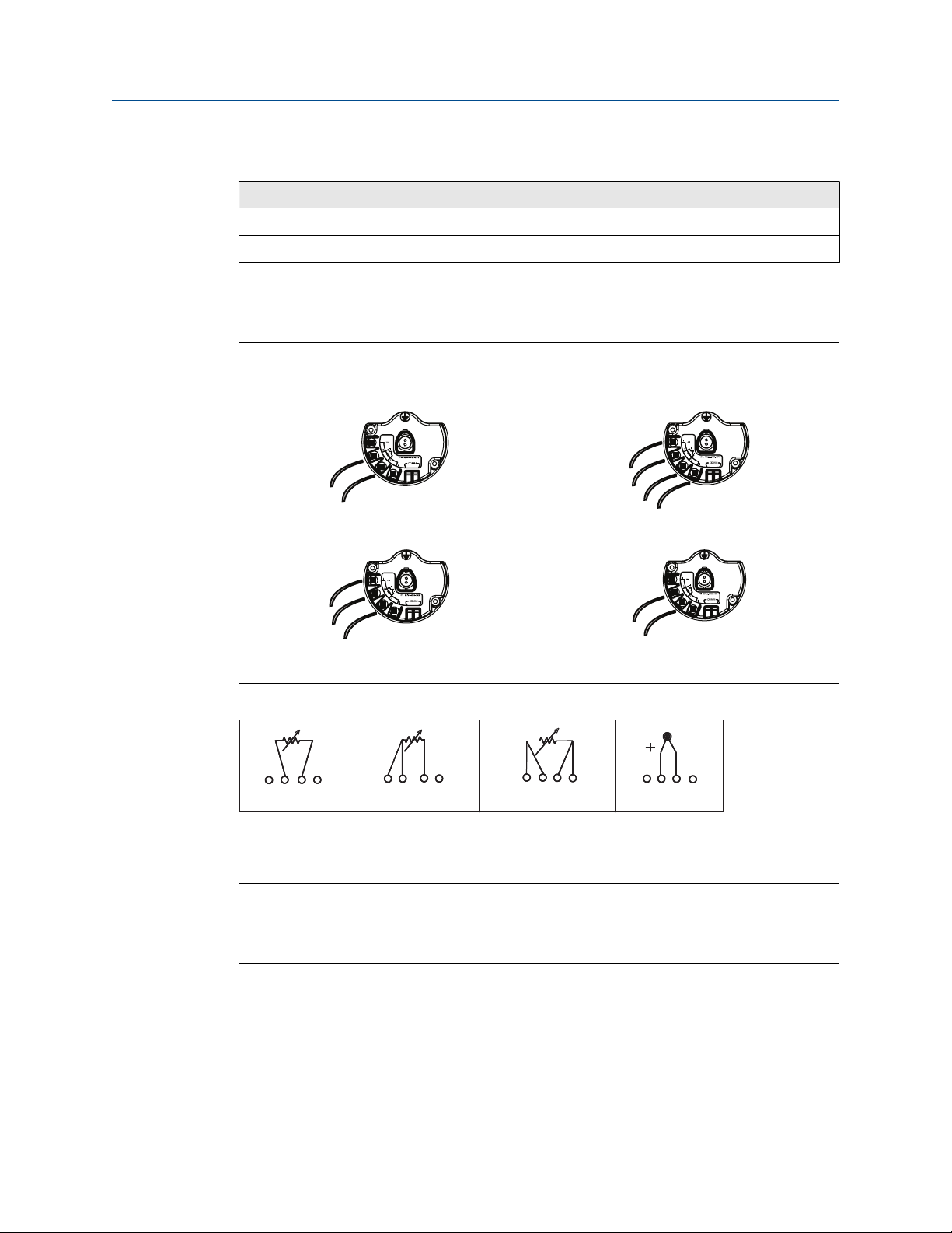
2.3 Sensor connections
The Rosemount 648 Wireless is compatible with a number of RTD and thermocouple
sensor types. Figure 2-1 shows the correct input connections to the sensor terminals on
the transmitter. To ensure a proper sensor connection, anchor the sensor lead wires into
the appropriate compression terminals and tighten the screws.
Make sensor connections through the cable entry in the side of the connection head. Be
sure to provide adequate clearance for cover removal.
When using Rosemount X-well Technology, the Rosemount 648 Wireless is required to be
assembled to a Rosemount 0085 Pipe Clamp RTD Sensor in a direct mount 3-wire
configuration.
Thermocouple or millivolts inputs
The thermocouple can be connected directly to the transmitter. Use appropriate
thermocouple extension wire if mounting the transmitter remotely from the sensor.
RTD or ohm inputs
The wireless transmitter will accept a variety of RTD or ohmic configurations, including 2-,
3-, or 4-wire connections. If the device is mounted remotely using a 3- or 4-wire
connection, it will operate withing specifications without recalibration for lead wire
resistances of up to 5 ohms per lead (equivalent to 500 ft. of 20 AWG wire). In this case,
the leads between the RTD and transmitter is recommended to be shielded.
2.3.1
Sensor lead wire resistance effect—RTD input
Since the lead wires are part of the RTD circuit, the lead wire resistance needs to be
compensated for to achieve the best accuracy. This becomes especially critical in
applications where long sensor and/or lead wires are used. There are three lead wire
configurations commonly available.
A 4-wire design is ideal because the lead wire resistance is inconsequential to the
measurement. It uses a measurement technique where a very small constant current of
about 150 micro amps is applied to the sensor through two leads and the voltage
developed across the sensor is measured over the other two wires with a high-impedance
and high resolution measuring circuit. In accordance with Ohm's Law, the high impedance
virtually eliminates any current flow in the voltage measurement leads and therefore the
resistance of the leads is not a factor.
In a 3-wire configuration, compensation is accomplished using the third wire with the
assumption that it will be the same resistance as the other two wires and the same
compensation is applied to all three wires.
In a 2-wire configuration there can be no compensation for lead wire resistance since the
lead wires are in series with the element and appear to the transmitter as part of the
sensor's resistance causing inherent accuracy degradation.
Table 2-1: Examples of Approximate Basic Error
Sensor input Approximate basic error
4-wire RTD Negligible
(1)
Rosemount 648 Wireless 11
Page 12
1 2 3 4
1 2 3 4
1 2 3 4
1 2 3 4
2-wire
RTD and Ω
3-wire
RTD and Ω
4-wire
RTD and Ω
T/C and mV
Configuration Reference Manual
May 2020 00809-0200-4648
Table 2-1: Examples of Approximate Basic Error (continued)
Sensor input Approximate basic error
3-wire RTD Error in reading is equivalent to unbalanced lead wire resistance
2-wire RTD Error in reading equivalent total lead wire resistance
(1) Independent of lead wire resistance up to 5Ω per lead.
(2) Unbalanced lead wire resistance is the maximum resistance differences between any of two
leads.
Figure 2-1: Sensor Wiring
Thermocouple/mV 4-Wire RTD and Ω
(2)
3-Wire RTD and Ω 2-Wire RTD and Ω
Figure 2-2: Sensor Connections
Note
Emerson provides 4-wire sensors for all single element RTDs. Use these RTDs in 3-wire
configurations by leaving the unneeded leads disconnected and insulated with electrical
tape.
12 Rosemount 648 Wireless
Page 13
White (1)
White (2)
Red (3)
Red (4)
White (1)
White (2)
Red (3)
Red (4)
+ White (2)
- Red (3)
+ Purple (2)
- Red (3)
+ Yellow (2)
- Red (3)
+ Blue (2)
- Red (3)
Reference Manual Configuration
00809-0200-4648 May 2020
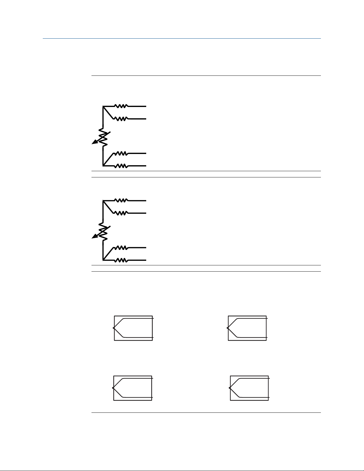
2.3.2 Lead wire configuration
Figure 2-3: Rosemount 68Q, 78 Standard Temperature Range, and 58 RTD Sensor
Single Element
Figure 2-4: Rosemount 65, 78 High Temp, 68 RTD Single Element
Figure 2-5: Rosemount 183 Thermocouple
Type J Type E
Type K Type T
Rosemount 648 Wireless 13
Page 14
+ Black (2)
- White (3)
+ Pink (2)
- White (3)
+ Green (2)
- White (3)
Configuration Reference Manual
May 2020 00809-0200-4648
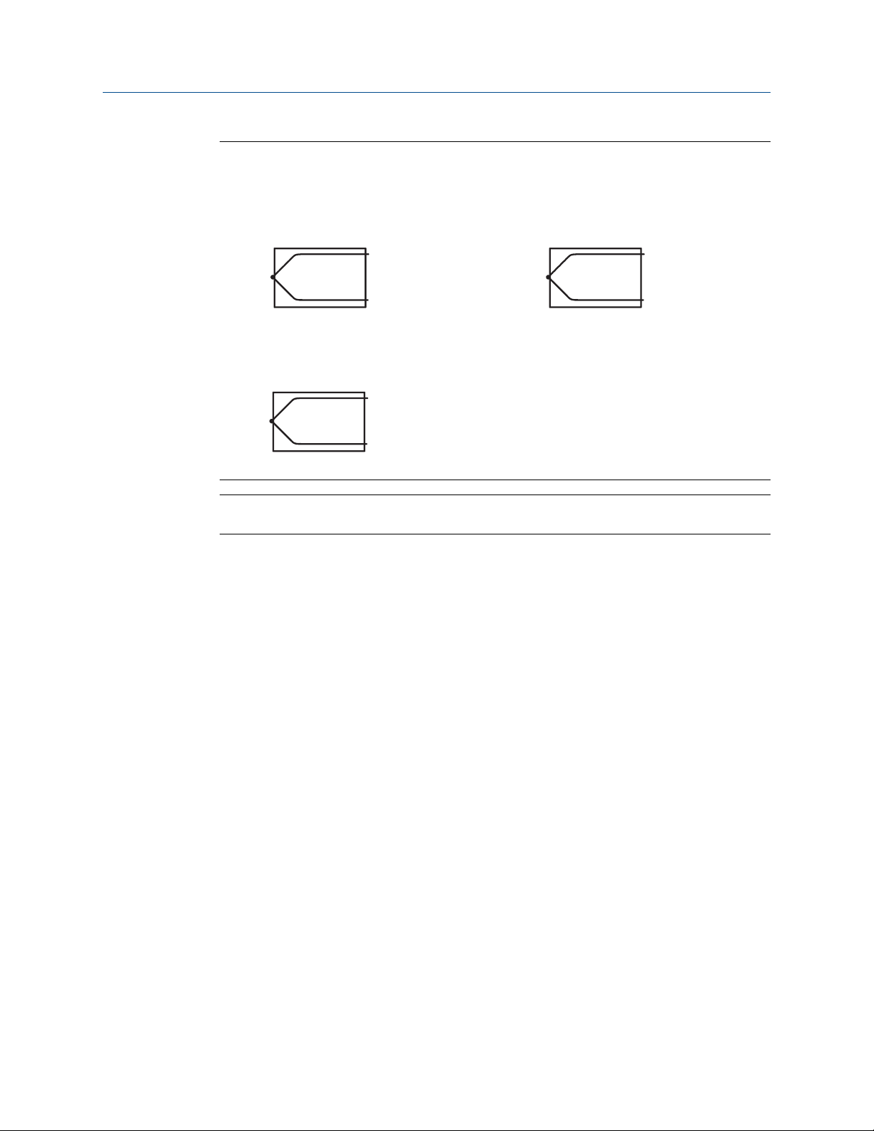
Figure 2-6: Rosemount 185 Thermocouple
Type J Type N
Type K
2.3.3
Note
Wire color examples apply to Rosemount sensors, but will vary by manufacturer.
Sensor leads
If the sensor is installed in a high-voltage environment and a fault condition or installation
error occurs, the sensor leads and transmitter terminals could carry lethal voltages. Use
extreme caution when making contact with the leads and terminals.
Use the following steps to wire the sensor and supply power to the transmitter:
1. Remove the transmitter enclosure cover (if applicable).
2. Attach the sensor leads according to the wiring diagrams.
3. Connect the power module.
4. Verify the connection by observing the LCD display (if applicable).
5. Reattach and tighten the cover (if applicable).
14 Rosemount 648 Wireless
Page 15
COMM
P/N 00753-9200-0020
1
2
3
4
Reference Manual Configuration
00809-0200-4648 May 2020
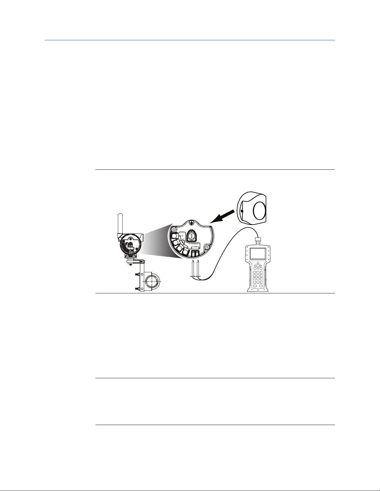
2.4 Bench top configuration
Bench top configuration consists of testing the transmitter and verifying transmitter
configuration data. The transmitter must be configured before installation, which may be
performed either directly or remotely. Direct configuration can be performed using a Field
Communicator, AMS Device Manager, AMS Wireless Configurator, or any WirelessHART
Communicator. Remote configuration can be performed using AMS Device Manager, AMS
Wireless Configurator, or the Wireless Gateway.
The power module must be installed to provide power to the transmitter for
configuration. To communicate to the transmitter, begin by removing the power moduleside housing cover, indicated as “Field terminals” by text located on the side of the device.
This will expose the terminal block and HART Communication terminals, which are labeled
“COMM”. Connect the power module to supply power for configuration. See Figure 2-7.
Figure 2-7: Connection Diagram for Rosemount 648 Wireless and Field
Communicator
™
2.4.1
Field Communicator
When performing device configuration directly, connect the bench equipment as shown
in Figure 2-7 above, and turn on the field communicator by pressing the ON/OFF key.
When using a Field Communicator, any configuration changes must be sent to the
transmitter by using the Send key (F2).
The Field Communicator will search for a HART®-compatible device and indicate when the
connection is made. If the Field Communicator fails to connect, it will indicate that no
device was found. If this occurs, refer to Troubleshooting.
Note
For HART Wireless transmitter communication via a Field Communicator, a Rosemount
648 Wireless Device Dashboard (DD) is required. Rosemount 648 Wireless Transmitters
equipped with Rosemount X-well Technology requires DD revision 648 Dev. 4 Rev. 1 or
higher to view Rosemount X-well functionality. To obtain the latest DD, visit
Emerson.com/Field-Communicator.
Rosemount 648 Wireless 15
Page 16

Configuration Reference Manual
May 2020 00809-0200-4648
2.4.2 AMS Device Manager and AMS Wireless Configurator
When configuring the Rosemount 648 Wireless using AMS Device Manager or AMS
Wireless Configurator, double click the Rosemount 648 Wireless device icon (or right click
and select Configure/Setup), then select the Configure/Setup tab. AMS Device Manager
configuration changes are implemented when the Apply button is selected.
Note
For HART Wireless transmitter communication via AMS Device Manager, a Rosemount
648 Wireless Device Dashboard (DD) is required. Rosemount 648 Wireless Transmitters
equipped with Rosemount X-well Technology requires DD revision 648 Dev. 4 Rev. 1 or
higher to view Rosemount X-well functionality. To obtain the latest DD, visit the Emerson
Easy Upgrade site.
2.4.3
2.4.4
Wireless Gateway
The Rosemount 648 Wireless supports limited remote configuration through the Wireless
Gateway. The Gateway allows configuration of the following device parameters: HART
Tag, Short Tag, Descriptor, Engineering Units, Update Rate and Range Values.
Default settings
The Rosemount 648 Wireless default configuration is shown below:
Sensor type
Engineering units °C
Number of lead wires 4
Network ID Factory-generated network parameters
Join Key Factory-generated network parameters
Update rate 1 minute
Note
The C1 option code can be used to enable factory configuration of the Update Rate, Date,
Descriptor and Message fields. This code is not required to have the factory configure the
Sensor Type, Connection or the Self Organizing Network parameters.
Pt 100 (α = 0.00386)
2.4.5
16 Rosemount 648 Wireless
Device sensor configuration
Every temperature sensor has unique characteristics. In order to ensure the most accurate
measurement, the device should be configured to match the specific sensor that it will be
connected to. Prior to installation, verify the configuration and connection settings of the
temperature sensor through a Field Communicator or AMS Device Manager.
Page 17
Reference Manual Configuration
00809-0200-4648 May 2020
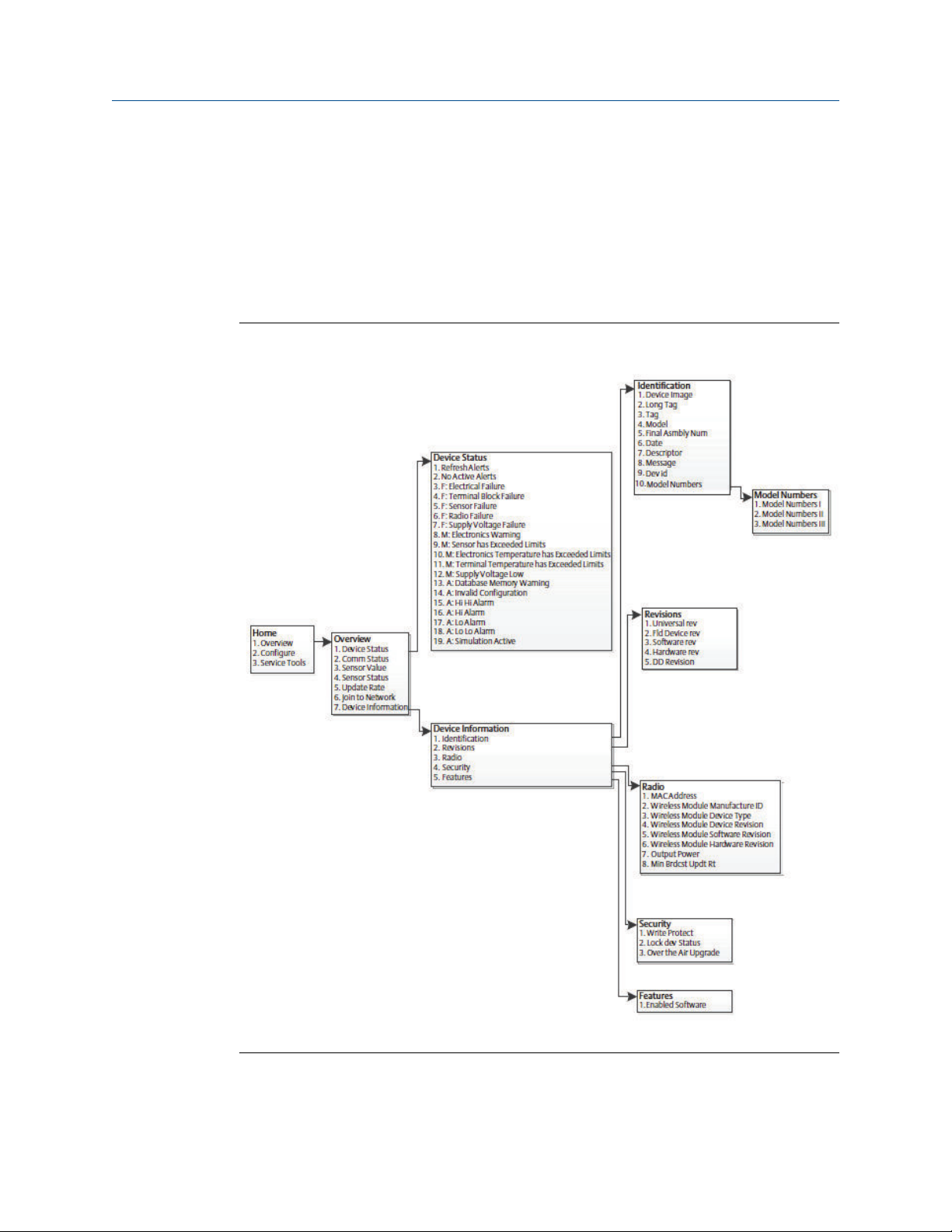
2.5 HART menu tree
This section displays the navigation paths to the primary commands and options via a Field
Communicator. For HART Wireless transmitter communication via a Field Communicator,
a Rosemount 648 Wireless Device Dashboard (DD) is required. Rosemount 648 Wireless
Transmitters with Rosemount X-well Technology requires DD revision 648 Dev. 4 Rev.1 or
higher to view Rosemount X-well functionality. To obtain the latest DD, visit the
Emerson.com/Field-Communicator.
Figure 2-8: Overview
Rosemount 648 Wireless 17
Page 18
Configuration Reference Manual
May 2020 00809-0200-4648
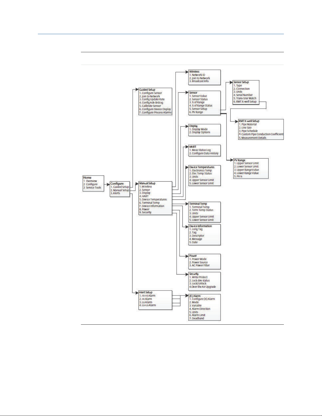
Figure 2-9: Configure
18 Rosemount 648 Wireless
Page 19
Reference Manual Configuration
00809-0200-4648 May 2020
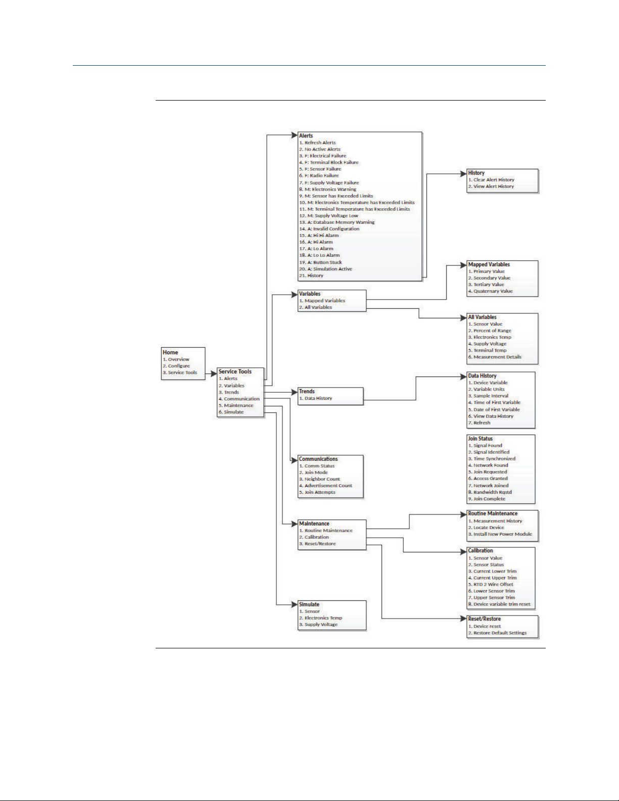
Figure 2-10: Service Tools
Rosemount 648 Wireless 19
Page 20

Configuration Reference Manual
May 2020 00809-0200-4648
2.6 Fast Key sequence
Table 2-2 lists the Fast Key sequences for common transmitter functions.
Note
The Fast Key sequences assumes that the latest Device Dashboard (DD) is being used. The
latest DD revision can be found on the title page of this document.
Table 2-2: Rosemount 648 Wireless Fast Key Sequence
Function Fast Key sequence Menu items
Device
Information
Guided Setup 2, 1 Configure Sensor, Join to Network, Config Advance
Manual Setup 2, 2 Wireless, Sensor, Display, HART, Device Temperature,
Wireless
Configuration
Sensor
Configuration
Sensor
Calibration
2, 2, 7 Tag, Long Tag, Descriptor, Message, Date
2, 2, 1 Network ID, Join to Network, Broadcast Info
2, 2, 2, 5 Type, Connection, Units, Serial Number, Transmitter-
3, 5, 2 Sensor Value, Sensor Status, Current Lower Trim,
2.7 Basic setup
2.7.1 Configure sensor type
Fast Keys 2, 1, 1
Broadcasting, Calibrate Sensor
Terminal Temperature, Device Information, Power,
Security
Sensor Matching, RMT X-well Setup
Current Upper Trim, RTD 2 Wire Offset, Lower Sensor
Trim, Upper Sensor Trim, Device variable trim reset
Every temperature sensor has unique characteristics to achieve the most accurate
measurement. Configure the wireless transmitter to match the specific sensor type.
Procedure
1. From the Home screen, select 2: Configure.
2. Select 1: Guided Setup
3. Select 1: Configure Sensor, then follow on the on-screen instructions to complete
the configuration.
This method allows selection of the number of lead wires and temperature
engineering units for the sensor.
20 Rosemount 648 Wireless
Page 21
Reference Manual Configuration
00809-0200-4648 May 2020
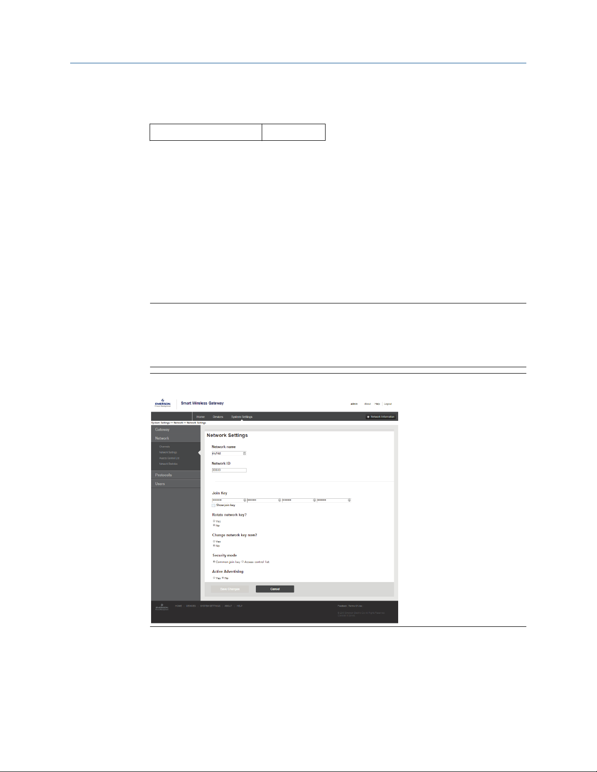
2.7.2 Join device to network
Fast key 2, 1, 2
To communicate with the Wireless Gateway, and ultimately the host system, the
transmitter must be configured to communicate over the wireless network. This step is
the wireless equivalent of connecting wires from a transmitter to the host system.
Procedure
1. From the Home screen, select 2: Configure.
2. Select 1: Guided Setup.
3. Select 2: Join to Network.
4. Using a Field Communicator or AMS Device Manager to communicate with the
transmitter, enter the Network ID and Join Key so they match the Network ID and
Join Key of the Wireless Gateway and the other devices in the network.
Note
If the Network ID and Join Key are not identical to those set in the Gateway, the
transmitter will not communicate with the network. The Network ID and Join Key may be
obtained from the Wireless Gateway on the System Settings → Network → etwork
Settings page of the Wireless Gateway web based user interface.
Figure 2-11: Wireless Gateway Network Settings Page
Rosemount 648 Wireless 21
Page 22
Configuration Reference Manual
May 2020 00809-0200-4648
2.7.3 Configure update rate
Fast Keys 2, 1, 3
The Update Rate is the frequency at which a new measurement is taken and transmitted
over the wireless network. This by default is one minute. This may be changed at
commissioning, or at any time via AMS Device Manager. The update rate is user selectable
from one second to 60 minutes.
Procedure
1. From the Home screen, select 2: Configure.
2. Select 1: Guided Setup.
3. Select 3: Configure Update Rate.
4. When the device configuration is completed, remove the power module and
replace the module cover.
Postrequisites
NOTICE
The power module should be inserted only when the device is ready to be commissioned.
Use caution when handling the power module.
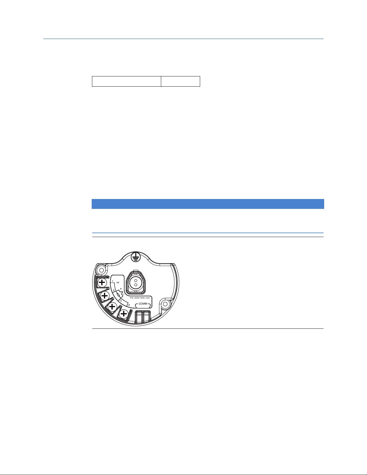
Figure 2-12: Terminal Block
Connect the HART® Communication leads to the COMM terminals on the terminal block.
22 Rosemount 648 Wireless
Page 23

COMM
P/N 00753-9200-0020
1
2
3
4
Reference Manual Configuration
00809-0200-4648 May 2020
Figure 2-13: Field Communicator Connections
2.8 Calibration
Calibrating the transmitter increases the measurement precision by allowing corrections
to be made to the factory-stored characterization curve by digitally altering the
transmitter’s interpretation of the sensor input.
To understand calibration, it is necessary to understand that smart transmitters operate
differently from analog transmitters. An important difference is that transmitters are
factory-characterized, meaning that they are shipped with a standard sensor curve stored
in the transmitter firmware. In operation, the transmitter uses this information to produce
a process variable output, in engineering units, dependent on the sensor input.
Calibration of the wireless transmitter may include the following procedures:
Sensor input trim:
Transmitter-sensor
matching:
2.8.1 Sensor input trim
Fast Key sequence 3, 5, 2
Perform a sensor trim if the transmitters digital value for the primary variable does not
match the plant’s standard calibration equipment. The sensor trim function calibrates the
sensor to the transmitter in temperature units or raw units. Unless your site-standard
input source is NIST-traceable, the trim functions will not maintain the NIST-traceability of
the system.
Digitally alter the transmitter’s interpretation of the input
signal
Generates a special custom curve to match that specific
sensor curve, as derived from the Callendar-Van Dusen
constants.
The Sensor Input Trim command allows the transmitter’s interpretation of the input signal
to be digitally altered. The sensor reference command trims, in engineering (°F, °C,°R, K) or
raw (Ω, mV) units, the combined sensor and transmitter system to a site standard using a
known temperature source. Sensor trimming is suitable for validation procedures or for
applications that require calibrating the sensor and transmitter together.
Rosemount 648 Wireless 23
Page 24

Configuration Reference Manual
May 2020 00809-0200-4648
Procedure
1. Connect the calibration device or sensor to the transmitter. Refer to Figure 2-1 on
page 9 or on the device terminal block for sensor wiring diagrams.
2. Connect the communicator to the transmitter.
3. From the Home screen, select 3 Service Tools → 5 Maintenance → 2 Calibration to
prepare to trim the sensor.
4. Select 6 Lower Sensor Trim or 7 Upper Sensor Trim.
Note
It is recommended to perform lower offset trims first, before performing upper
slope trims.
5. Answer the question about using an active calibrator or not.
6. Adjust the calibration device to the desired trim value (must be within the selected
sensor limits). If a combined sensor and transmitter system are being trimmed,
expose the sensor to a known temperature and allow the temperature reading to
stabilize. Use a bath, furnace or isothermal block, measured with a site-standard
thermometer, as the known temperature source.
7. Select OK once the temperature stabilizes. The communicator displays the output
value the transmitter associates with the input value provided by the calibration
device.
8. Select the appropriate sensor trim units at the prompt.
9. Enter the trim point.
2.8.2
Transmitter-sensor matching
Fast Key sequence 2, 1, 1
Perform the transmitter-sensor matching procedure to enhance the temperature
measurement accuracy of the system (see the comparison below) and if you have a sensor
with Callendar-Van Dusen constants. When ordered from Emerson, sensors with
Callendar-Van Dusen constants are NIST-traceable.
The wireless transmitter accepts Callendar-Van Dusen constants from a calibrated RTD
schedule and generates the actual curve to match that specific sensor curve.
24 Rosemount 648 Wireless
Page 25

Resistance, Ohm
Temperature, °C
0 °C
Standard IEC 751
“Ideal” Curve*
Actual Curve
Reference Manual Configuration
00809-0200-4648 May 2020
Figure 2-14: Standard vs. Actual Sensor Curve
*The Actual Curve is identified from the Callendar-Van Dusen equation.
System accuracy comparison at 150 °C using a PT 100 (A=0.00385) RTD with a span of 0 to
200 °C
Standard RTD Matched RTD
Rosemount 648 Wireless ±0.45 °C Rosemount 648 Wireless ±0.45 °C
Standard RTD ±1.05 °C Matched RTD ±0.18 °C
Total System
(1) Calculated using root-summed-squared (RSS) statistical method.
(1)
±1.14 °C Total System
Total system accuracy = ( Transmitter accuracy)2 + (Sensor accuracy)
(1)
±0.48 °C
2
Callendar-Van Dusen equation
Rt = Ro + Roα [t - δ(0.01t-1)(0.01t) - β(0.01t - 1)(0.01t)3]
The following input variables, included with specially-ordered Rosemount temperature
sensors, are required:
Ro = Resistance at Ice Point Alpha = Sensor Specific Constant Beta = Sensor Specific
Constant Delta = Sensor Specific Constant
To input Callendar-Van Dusen constants, perform the following procedure:
Procedure
1. From the Home screen, select 2 Configure → 1 Guided Setup → 1 Configure
Sensor → 1 Configure Type and Units and press Enter.
2. Select Cal VanDusen at the Select Sensor Type prompt.
3. Select the appropriate number of wires at the Select Sensor Connection prompt.
4. Enter the Ro, Alpha, Delta, and Beta values from the stainless steel tag attached to
the special-order sensor when prompted.
5. Select desired other options and select Enter.
Rosemount 648 Wireless 25
Page 26

Configuration Reference Manual
May 2020 00809-0200-4648
6. To disable the Transmitter-sensor matching feature from the Home screen select
Configure → Guided Setup → Configure Sensor → Configure Sensor Type and
Units and press Enter. Select the appropriate sensor type from the Select Sensor type
prompt.
Note
When the transmitter-sensor matching is disabled, the transmitter reverts to
factory trim. Ensure the transmitter engineering units default correctly before
placing the transmitter into service.
26 Rosemount 648 Wireless
Page 27

Reference Manual Configuration
00809-0200-4648 May 2020
2.9 Advanced setup
2.9.1 LCD display
The LCD display configuration command allows customization of the LCD display to suit
application requirements. The LCD display will alternate between the selected items:
• Temperature units
• Sensor temperature
• % of range
• Supply voltage
Reference LCD display screen messages for images of LCD display screens.
Configuring LCD display with Field Communicator
Fast Keys
Transmitter ordered with the LCD display will be shipped with display installed and
enabled.
If the transmitter was ordered without the LCD display or if the LCD display was disabled,
follow these steps to enable the LCD display on the transmitter.
Procedure
1. From the Home screen, select 2: Configure.
2. Select 1: Guided Setup.
3. Select 6: Configure Device Display.
4. Select the Periodic option.
5. Select desired display options and select Enter.
2, 1, 6
Configuring LCD display with AMS Device Manager
Procedure
1. Right click on the device and select Configure.
2. Under Optional Setup, select Configure Device Display button.
3. Select desired display options and select Enter.
Note
The LCD display can be order as a spare part with part number: 00753-9004-0002.
2.9.2
Rosemount 648 Wireless 27
Rosemount X-well technology
The Rosemount 648 Wireless can be ordered with Rosemount X-well technology via the
“PT” model option code. The”C1” model option code must be ordered if the “PT” option
Page 28

Configuration Reference Manual
May 2020 00809-0200-4648
code is specified. The “C1’ option code requires user supplied information of process pipe
material and pipe schedule. Rosemount X-well technology can be configured with any
asset management software that supports Electronic Device Description Language
(EDDL). The Device Dashboard interface with DD revision 648 Dev. 4 Rev. 1 or higher is
required to view Rosemount X-well functionality.
The “Rosemount X-well Process” sensor/type option should be selected as the sensor type
in most cases. Once selected, pipe material, line size, and pipe schedule information is
required when configuring Rosemount X-well technology. This section is referring to the
process pipe properties that Rosemount 648 Wireless and 0085 Pipe Clamp Sensor with
Rosemount X-well technology is going to be installed in. This information is required for
the in-transmitter algorithm to accurately calculate process temperature.
In the rare case that the process pipe is not available, a custom value for the pipe
conduction coefficient can be entered. This field becomes available when the “Rosemount
X-well Custom” sensor/type option is selected.
Configure Rosemount X-well technology with Field Communicator
Procedure
1. From the Home screen, select 2: Configure.
2. Select 1: Guided Setup.
3. Select 1: Configure Sensor.
4. Select 1: Configure Sensor Type and Units.
5. Select either Rosemount X-well Process or Rosemount X-well Custom.
6. Select desired configurations and select Enter.
28 Rosemount 648 Wireless
Page 29

Reference Manual Configuration
00809-0200-4648 May 2020
Configure Rosemount X-well technology with AMS Device Manager
Procedure
1. Right click on the device and select Configure.
2. In the menu tree, select Manual Setup.
3. Select the Sensor tab.
4. Select either Rosemount X-well Process or Rosemount X-well Custom.
5. Select desired configurations and select Send.
Figure 2-15: Manual Setup - Sensor Screen for the Rosemount 648 Wireless
with Rosemount X-well Technology
View Rosemount X-well measurement details
To view live data and trending for measured ambient temperature, measured surface
temperature, and calculated process temperature, perform the following procedure:
Procedure
1. Right click on the device and select Configure.
2. In the menu tree, select Manual Setup.
3. Select the Sensor tab.
4. Select the Measurement Details button.
Rosemount 648 Wireless 29
Page 30

Deadband
Assigned Value
Alert Set Point
Alert “OFF” Alert “ON” Alert “OFF”
Units of Measurement
Time
Configuration Reference Manual
May 2020 00809-0200-4648
Figure 2-16: Rosemount X-well Measurement Details Page
2.9.3 Process alerts
Fast Key sequence 2, 1, 7
Process alerts allow the user to configure the transmitter to output a HART message when
the configured data point is exceeded. An alert will be transmitter continuously if the set
points are exceeded and the alert mode is ON. An alert will be displayed on a Field
Communicator, AMS Device Manager status screen or in the error section of the LCD
display. The alert will reset once the value returns within range.
Note
HI alert value must be higher than the LO alert value. Both alert values must be within the
temperature sensor limits.
Figure 2-17: Example 1: Rising Alert
30 Rosemount 648 Wireless
Page 31

Deadband
Assigned Value
Alert Set Point
Alert “OFF” Alert “ON” Alert “OFF”
Units of Measurement
Time
Reference Manual Configuration
00809-0200-4648 May 2020
Figure 2-18: Example 2: Falling Alert
Field Communicator
To configure the process alerts with a Field Communicator, perform the following
procedure:
Procedure
1. From the HOME screen, follow the Fast Key sequence, 2 Configure → 1 Guided
Setup → 1 Guided Setup.
2. Select 2 for Hi-Hi Alarm, or Select 3 for Hi Alarm, or Select 4 for LO Alarm, or
Select 5 for LO-LO Alarm and press Enter.
3. If the alarm is disabled, select 1 Enable and press Enter. If the alarm was previously
enabled, select 2 Leave Enabled and press Enter.
4. Enter the alarm limit and press Enter.
5. Enter the alarm deadband and press Enter.
2.10 Remove power module
After the sensor and network have been configured, remove the Power Module and
replace the transmitter cover. The Power Module should be inserted only when the device
is ready to be commissioned. Use caution when handling the Power Module. The Power
Module may be damaged if dropped from heights in excess of 20 feet.
Rosemount 648 Wireless 31
Page 32

Configuration Reference Manual
May 2020 00809-0200-4648
32 Rosemount 648 Wireless
Page 33

Reference Manual Installation
00809-0200-4648 May 2020
3 Installation
3.1 Overview
The information in this section covers installation considerations. Instructions on how to
access Dimensional drawings for each Rosemount 648 Wireless variation and mounting
configuration are included in Rosemount 648 Wireless Product Data Sheet.
3.2 Safety messages
Instructions and procedures in this section may require special precautions to ensure the
safety of the personnel performing the operations. Information that potentially raises
safety issues is indicated by a warning symbol ( ). Refer to the following safety messages
before performing an operation preceded by this symbol.
WARNING
Follow instructions
Failure to follow these installation guidelines could result in death or serious injury.
Ensure only qualified personnel perform the installation.
Explosions
Explosions could result in death or serious injury.
Installation of this transmitter in an explosive environment must be in accordance with the
appropriate local, national, and international standards, codes, and practices. Review the
approvals section of this manual for any restrictions associated with a safe installation.
Before connecting a communicator in an explosive atmosphere, ensure the instruments in
the segment are installed in accordance with intrinsically safe or non-incendive field wiring
practices.
Process leaks
Process leaks could result in death or serious injury.
Install and tighten process connectors before applying pressure.
Electrical shock
Electrical shock could cause death or serious injury.
Avoid contact with the leads and terminals. High voltage that may be present on leads can
cause electrical shock.
Rosemount 648 Wireless 33
Page 34

Installation Reference Manual
May 2020 00809-0200-4648
WARNING
This device complies with Part 15 of the FCC Rules. Operation is subject to the
following conditions:
This device may not cause harmful interference.
This device must accept any interference received, including interference that may cause
undesired operation.
This device must be installed to ensure a minimum antenna separation distance of 8-in.
(20 cm) from all persons.
The power module may be replaced in a hazardous area. The power module has surface
resistivity greater than one gigaohm and must be properly installed in the wireless device
enclosure. Care must be taken during transportation to and from the point of installation
to prevent electrostatic charge build-up.
Physical access
Unauthorized personnel may potentially cause significant damage to and/or
misconfiguration of end users’ equipment. This could be intentional or unintentional and
needs to be protected against.
Physical security is an important part of any security program and fundamental to
protecting your system. Restrict physical access by unauthorized personnel to protect end
users’ assets. This is true for all systems used within the facility.
3.3 Wireless considerations
3.3.1 Power up sequence
The Rosemount 648 Wireless and all other wireless devices should be installed only after
the Wireless Gateway (“Gateway”) has been installed and is functioning properly. Wireless
devices should also be powered up in order of proximity from the Gateway, beginning with
the closest. This will result in a simpler and faster network installation. Enable active
advertising on the Gateway to ensure new devices join the network faster. For more
information, see the Wireless Gateway Reference Manual.
3.3.2
Antenna position
The antenna should be positioned vertically, either straight up or straight down, and it
should be approximately 3 ft. (1 m) from any large structure, building, or conductive
surface to allow for clear communication to other devices.
34 Rosemount 648 Wireless
Page 35

$
$
Reference Manual
00809-0200-4648 May 2020
Figure 3-1: Antenna Position
Installation
3.3.3 Conduit entry
Upon installation, ensure each conduit entry is either sealed with a conduit plug using
approved thread sealant, or has an installed conduit fitting or cable gland with appropriate
threaded sealant.
3.3.4
Note
The conduit entries on the Emerson 781 Field Link are threaded ½–14 NPT.
Figure 3-2: Conduit Entry
A. Conduit entry
Field Communicator connections
The Black Power Module needs to be installed in the device for the Field Communicator to
interface with the Rosemount 648 Wireless. For HART Wireless Transmitter
communication via a Field Communicator, a Rosemount 648 Wireless Device Dashboard
(DD) is required. Rosemount 648 Wireless Transmitters equipped with Rosemount X-well
Technology requires DD revision 648 Dev. 4 Rev. 1 or higher to view Rosemount X-well
functionality. To obtain the latest DD, visit the Field Communicator System Software and
Device Description site at: Emerson.com/Field-Communicator
Refer to Figure 3-3 for instructions on connecting the Field Communicator to the
Rosemount 648 Wireless Transmitter.
Rosemount 648 Wireless 35
Page 36

COMM
P/N 00753-9200-0020
1
2
3
4
Installation
Reference Manual
May 2020 00809-0200-4648
Figure 3-3: Connection
3.4 Physical installation
3.4.1 Transmitter installation
The transmitter can be installed in one of two configurations:
• Direct Mount, where the sensor is connected directly to the Rosemount 648 Wireless
housing’s conduit entry.
• Remote Mount, where the sensor is mounted separate from the Rosemount 648
Wireless housing, then connected to the transmitter using conduit.
Select the installation sequence that corresponds to the mounting configuration.
3.4.2
Direct mount
The direct mount installation should not be used when installing with a Swagelok® fitting.
Procedure
1. Install sensor according to standard installation practices using approved thread
sealant on all connections.
2. Attach transmitter housing to the sensor using the threaded conduit entry.
3. Attach sensor wiring to the terminals as indicated on the wiring diagram.
4. Connect Black Power Module.
Note
Wireless devices should be powered up in order of proximity from the Wireless
Gateway, beginning with the closest device to the gateway. This will result in a
simpler and faster network installation.
36 Rosemount 648 Wireless
Page 37

Reference Manual
00809-0200-4648 May 2020
Figure 3-4: Installing Electronics Housing Cover
5. Close housing cover and tighten to safety specification. Always ensure a proper seal
by installing the electronics housing covers so metal touches metal, but do not over
tighten.
6. Position antenna vertically, either straight up or straight down. The antenna should
be approximately 3 ft. (1 m) from any large structures or buildings, to allow clear
communication to other devices.
Installation
3.4.3
Figure 3-5: Possible Antenna Rotation
Remote mount
Procedure
1. Install sensor according to standard installation practices using an approved thread
sealant on all connections.
2. Run wiring (and conduit, if necessary) from the sensor to the transmitter.
3. Pull wiring through the threaded conduit entry of the transmitter.
4. Attach sensor wiring to the terminals as indicated on the wiring diagram.
5. Connect Black Power Module.
Rosemount 648 Wireless 37
Page 38

Installation Reference Manual
May 2020 00809-0200-4648
Note
Wireless devices should be powered up in order of proximity from the wireless
gateway, beginning with the closest device to the Gateway. This will result in a
simpler and faster network installation.
Figure 3-6: Installing Electronics Housing Cover
6. Close housing cover and tighten to safety specification. Always ensure a proper seal
by installing the electronics housing covers so metal touches metal, but do not over
tighten.
7. Position antenna vertically, either straight up or straight down.The antenna should
be approximately 3 ft. (1 m) from any large structures or buildings to allow clear
communication to other devices.
Figure 3-7: Possible Antenna Rotation
38 Rosemount 648 Wireless
Page 39

Reference Manual Installation
00809-0200-4648 May 2020
3.4.4 Rosemount X-well Installation
Rosemount X-well Technology is only available in the Rosemount 648 Wireless and 0085
pipe clamp sensor factory assembled complete point solution. Rosemount X-well
Technology will only work as specified with factory supplied and assembled pipe clamp
sensor.
In general, pipe clamp sensor installation best practices shall be followed (see Rosemount
0085 Pipe Clamp Sensor Reference Manual) with Rosemount X-well Technology specific
requirements noted below:
Procedure
1. Direct mounting of transmitter on pipe clamp sensor is required for Rosemount X-
well Technology to properly function.
2. Transmitter head shall be placed away from dynamic external temperature sources
such as a boiler.
3. Insulation (½-in. thick minimum) is required over the sensor clamp assembly and
sensor extension up to transmitter head to prevent heat loss. Apply a minimum of
six inches of insulation on each side of the pipe clamp sensor. Care should be taken
to minimize air gaps between insulation and pipe. See Figure 3-8.
Note
DO NOT apply insulation over transmitter head.
4. Although it will come factory configured as such, ensure that pipe clamp RTD
sensor is assembled in 3-wire configuration. See #unique_14/
unique_14_Connect_42_section_rkb_bb1_qkb for more information.
Figure 3-8: Rosemount 648 Wireless with Rosemount X-well Technology
Installation Drawing
Rosemount 648 Wireless 39
Page 40

A
B
C
Installation
May 2020 00809-0200-4648
Reference Manual
3.4.5 LCD display
Transmitters ordered with the optional LCD display will be shipped with the display
installed. The LCD display can be rotated in 90 degree increments by squeezing the two
tabs, pulling out, rotating and snapping back into place. If LCD display pins are
inadvertently removed from the interface board, carefully re-insert the pins before
snapping the LCD display back into place.
Procedure
1. Remove the LCD display cover. Do not remove the instrument covers in explosive
environments when the circuit is live.
2. Put the 4-pin connector into the LCD display, rotate to the desired position and
snap into place.
3. Replace the transmitter cover.
The following LCD display temperature limits:
• Operating:–4 to 175 °F (–20 to 80 °C)
• Storage:–40 to 185 °F (–40 to 85 °C)
Note
Only use Rosemount Wireless LCD Display part number: 00753-9004-0002.
Figure 3-9: Optional LCD Display
A. LCD display pins
B. LCD display display
C. LCD display cover
3.5 Ground the transmitter
The transmitter will operate with the housing either floating or grounded. However, the
extra noise in floating systems affects many types of readout devices. If the signal appears
noisy or erratic, grounding the transmitter at a single point may solve the problem.
The electronics enclosure should be grounded in accordance with local and national
installation codes. This can be accomplished via the process connection, via the internal
case grounding terminal, or via the external grounding terminal.
40 Rosemount 648 Wireless
Page 41

A
B
C
Reference Manual Installation
00809-0200-4648 May 2020
3.5.1 Thermocouple, mV, and RTD/Ohm inputs
Each process installation has different requirements for grounding. Use the grounding
options recommended by the facility for the specific sensor type, or begin with grounding
Option 1 (the most common).
Option 1
Procedure
1. Connect sensor wiring shield to the transmitter housing (only if the housing is
grounded)
2. Ensure the transmitter housing is electrically isolated from the sensor wiring.
A. Sensor wires
B. Transmitter
C. Shield ground point
Option 2
Procedure
1. Ground sensor wiring shield at the sensor.
2. Ensure the sensor wiring and shield is electrically isolated from the transmitter
housing.
Rosemount 648 Wireless 41
Page 42

A
B
C
Installation Reference Manual
May 2020 00809-0200-4648
A. Sensor wires
B. Transmitter
C. Shield ground point
Note
Always use facility recommended wiring practices.
3.6 Fast Key sequence
Table 3-1 lists the Fast Key sequences for common transmitter functions.
Table 3-1: Fast Key Sequence
Function Fast Key sequence Menu items
Device Information 2, 2, 7 Tag, Long Tag, Descriptor, Message, Date
Guided Setup 2, 1 Configure Sensor, Join to Network, Config
Manual Setup 2, 2 Wireless, Sensor, Display, HART, Device
Wireless Configuration 2, 2, 1 Network ID, Join to Network, Broadcast
Sensor Configuration 2, 2, 2, 5 Type, Connection, Units, Serial Number,
Sensor Calibration 3, 5, 2 Sensor Value, Sensor Status, Current
Advance Broadcasting, Calibrate Sensor
Temperature, Terminal Temp, Device
Information, Power, Security
Info
Transmitter-Sensor Matching, RMT X-well
Setup
Lower Trim, Current Upper Trim, RTD 2
Wire Offset, Lower Sensor Trim, Upper
Sensor Trim, Device variable trim reset
42 Rosemount 648 Wireless
Page 43

Reference Manual Commissioning
00809-0200-4648 May 2020
4 Commissioning
4.1 Overview
The information in this section contains techniques to properly commissioning the device.
A Rosemount 648 Quick Start Guide is shipped with every transmitter to describe basic
installation and startup procedures.
4.2 Safety messages
Instructions and procedures in this section may require special precautions to ensure the
safety of the personnel performing the operations. Information that potentially raises
safety issues is indicated by a warning symbol ( ). Refer to the following safety messages
before performing an operation preceded by this symbol.
WARNING
Follow instructions
Failure to follow these installation guidelines could result in death or serious injury.
Ensure only qualified personnel perform the installation.
Explosions
Explosions could result in death or serious injury.
Installation of this transmitter in an explosive environment must be in accordance with the
appropriate local, national, and international standards, codes, and practices. Review the
approvals section of this manual for any restrictions associated with a safe installation.
Before connecting a communicator in an explosive atmosphere, ensure the instruments in
the segment are installed in accordance with intrinsically safe or non-incendive field wiring
practices.
Process leaks
Process leaks could result in death or serious injury.
Install and tighten process connectors before applying pressure.
Electrical shock
Electrical shock could cause death or serious injury.
Avoid contact with the leads and terminals. High voltage that may be present on leads can
cause electrical shock.
Rosemount 648 Wireless 43
Page 44

Commissioning Reference Manual
May 2020 00809-0200-4648
WARNING
This device complies with Part 15 of the FCC Rules. Operation is subject to the
following conditions:
This device may not cause harmful interference.
This device must accept any interference received, including interference that may cause
undesired operation.
This device must be installed to ensure a minimum antenna separation distance of 8-in.
(20 cm) from all persons.
The power module may be replaced in a hazardous area. The power module has surface
resistivity greater than one gigaohm and must be properly installed in the wireless device
enclosure. Care must be taken during transportation to and from the point of installation
to prevent electrostatic charge build-up.
Physical access
Unauthorized personnel may potentially cause significant damage to and/or
misconfiguration of end users’ equipment. This could be intentional or unintentional and
needs to be protected against.
Physical security is an important part of any security program and fundamental to
protecting your system. Restrict physical access by unauthorized personnel to protect end
users’ assets. This is true for all systems used within the facility.
44 Rosemount 648 Wireless
Page 45

A b c d e
f g h
i d - 1 2
3 4 5 6 7 8
n e t w k
13 0 5
I D
n e t w k
O K
s n s r
1 0. 0 2
d e g c
N E T w K
S R C H N G
n e t w k
N E G O T
n e t w k
L I M - O P
n e t w k
O K
Reference Manual Commissioning
00809-0200-4648 May 2020
4.3 Verify operation
The transmitter can be commissioned before or after installation. It may be useful to
commission it on the bench, before installation, to ensure proper operation and to
become familiar with its functionality. When applicable, make sure the instruments are
installed in accordance with intrinsically safe or non-incendive field wiring practices. The
device will be powered whenever the power module is installed. To avoid depleting the
power module, make sure it is removed when the device is not in use.
Operation can be verified in four locations: at the device via the LCD display, using a Field
Communicator, the Wireless Gateway's integrated web interface, or using AMS Suite
Wireless Communicator or AMS Device Manager.
4.3.1 LCD display
During normal operation, the LCD display will display the PV value at the wireless transmit
rate up to as fast as one minute intervals. Refer to LCD display screen messages for error
codes and other LCD display messages. Press the Diagnostic button to display the TAG,
Device ID, Network ID, Network Join Status and Device Status screens. For Device Status
screens, see .
Figure 4-1: Diagnostic Screen Sequence
Tag Device ID Network ID Network status Device variables
Figure 4-2: Network Status Screens
Searching for
network
Joining network Connected with
1 parent
Connected with
2 parents
Rosemount 648 Wireless 45
Page 46

Commissioning Reference Manual
May 2020 00809-0200-4648
4.3.2 Field Communicator
For HART Wireless transmitter communication via a Field Communicator, a Rosemount
648 Wireless Device Dashboard (DD) is required. Rosemount 648 Wireless Transmitter
equipped with Rosemount X-well Technology requires DD revision 648 Dev. 4 Rev. 1 or
higher to view Rosemount X-well functionality. To obtain the latest DD, visit the
Emerson.com/Field-Communicator.
The communication status may be verified in the wireless device using the following Fast
Key sequence.
Function Fast Key sequence Menu items
Communication 3, 4 Comm, Join Mode, Neighbor Count, Advertisement
Count, Join Attempts
4.3.3 Wireless Gateway
If the Rosemount 648 Wireless was configured with the Network ID and Join Key and
sufficient time for network polling has passed, the transmitter will be connected to the
network. To verify device operation and connectivity using the Wireless Gateway's web
based user interface, navigate to the Devices page. This page will also display the
transmitter's tag, PV, SV, TV, QV, and Last Update time. Refer to Emerson Wireless
Gateway Manual Supplement for terms, user fields, and parameters used in the Wireless
Gateway web based user interface.
Note
The time to join the new device(s) to the network is dependent upon the number of
devices being joined and the number of devices in the current network. For one device
joining an existing network with multiple devices, it may take up to five minutes. It may
take up to 60 minutes for multiple new devices to join the existing network.
Figure 4-3: Wireless Gateway Devices Page
46 Rosemount 648 Wireless
Page 47

Reference Manual Commissioning
00809-0200-4648 May 2020
4.3.4 AMS Wireless Configurator
For HART Wireless transmitter communication via AMS Wireless Configurator, a
Rosemount 648 Wireless Device Dashboard (DD) is required. Rosemount 648 Wireless
Transmitters equipped with Rosemount X-well technology requires DD revision 648 Dev. 4
Rev. 1 or higher to view Rosemount X-well functionality. To obtain the latest DD, visit the
Emerson.com/Field-Communicator.
Figure 4-4: AMS Wireless Configurator Explorer Window
Rosemount 648 Wireless 47
Page 48

Commissioning Reference Manual
May 2020 00809-0200-4648
48 Rosemount 648 Wireless
Page 49

X X X X X
X X X X x x x
x x x x x x
6 4 8
W I r e l s
A b c d e
f g h
s n s r
1 0. 0 2
d e g c
Reference Manual Operation and maintenance
00809-0200-4648 May 2020
5 Operation and maintenance
5.1 LCD display screen messages
5.1.1 Startup screen sequence
The following screens will display when the power module is first connected to the
Rosemount™ 648 Wireless Temperature Transmitter.
All Segments On: used to visually determine if there are
any bad segments on the LCD display
Device Identification: used to determine Device Type
Device Information - Tag: user entered tag which is eight
characters long - will not display if all characters are blank
PV Screen: process temperature, ohms or mV value
depending on how the device is configured
Rosemount 648 Wireless 49
Page 50

T E R M
2 5. 0 0
d e g c
D E V
2 5. 2 5
d e g c
S u p l y
7. 2 1
v o l t s
a l e r t
p r e s n t
Operation and maintenance Reference Manual
May 2020 00809-0200-4648
SV Screen: terminal temperature value
TV Screen: feature board temperature value
QV Screen: voltage reading at the power module
terminals
Alert Screen: at least one alert is present - this screen will
not display if no alerts are present
50 Rosemount 648 Wireless
Page 51

A b c d e
f g h
i d - 1 2
3 4 5 6 7 8
n e t w k
O K
n e t w k
O K
S u p l y
7. 2 1
v o l t s
Reference Manual Operation and maintenance
00809-0200-4648 May 2020
5.1.2 Diagnostic button screen sequence
The following five screens will display when the device is operating properly and the
Diagnostic Button has been pressed.
Device Information - Tag: user entered tag which is 8
characters long - will not display if all characters are blank
Device Identification: used to determine Device ID
Diagnostic Button Screen 3: assuming the device has the
correct join key, this ID tells the user what network the
device can connect with
Diagnostic Button Screen 4.11: the device has joined a
network and has been fully configured and has multiple
parents
Diagnostic Button Screen 5: voltage reading at the power
module terminals
Rosemount 648 Wireless 51
Page 52

n e t w k
u n k n w n
n e t w k
a c t i v e
n e t w k
N E G O T
N E T w K
S R C H N G
n e t w k
p - s r c h
Operation and maintenance Reference Manual
May 2020 00809-0200-4648
5.1.3 Network diagnostic status screens
These screens display the network status of the device. Only one will be shown during the
startup sequence or diagnostic sequence.
Diagnostic Button Screen 4.1: the device has yet to
retrieve the information from the Smart Wireless Gateway
and is still in the process of being activated
Diagnostic Button Screen 4.2: the device has received
the ACTIVATE command from the Smart Wireless
Gateway, but is in the process of being configured to the
wireless network
Diagnostic Button Screen 4.3: the device has sent JOIN
request and is waiting for the ACTIVATE command
Diagnostic Button Screen 4.4: the device is in active
search
Diagnostic Button Screen 4.5: the device is in passive
search
52 Rosemount 648 Wireless
Page 53

n e t w k
i d l e
n e t w k
c o n e c t
n e t w k
r e s e t
n e t w k
b c k o f f
n e t w k
L I M - O P
Reference Manual Operation and maintenance
00809-0200-4648 May 2020
Diagnostic Button Screen 4.6: the device couldn’t find
the network and is in deep sleep mode to preserve power
module life
Diagnostic Button Screen 4.7: the device synchronized to
a network
Diagnostic Button Screen 4.8: the device will reset
Diagnostic Button Screen 4.9: the device couldn’t join
because of dropped packets and will reset
Diagnostic Button Screen 4.10: the device has joined a
network and has been fully configured but has only one
parent device
Rosemount 648 Wireless 53
Page 54

D E V
f A i l u r
s n s r
1 0. 0 2
d e g c
T E R M
2 5. 0 0
d e g c
D E V
2 5. 2 5
d e g c
S u p l y
7. 2 1
v o l t s
Operation and maintenance Reference Manual
May 2020 00809-0200-4648
5.1.4 Device diagnostic screens
The following screens will show the device diagnostics depending on the state of the
device.
Device Information - Status: there is a critical error which
may prevent the device from operating correctly. Check
additional status screens for more information.
PV Screen: process temperature, ohms or mV value
depending on how the device is configured
SV Screen: terminal temperature value
TV Screen: feature board temperature value
QV Screen: voltage reading at the power module
terminals
54 Rosemount 648 Wireless
Page 55

a l e r t
p r e s n t
A b c d e
f g h
i d - 1 2
3 4 5 6 7 8
s u p l y
f a i l u r
s u p l y
l o w
Reference Manual Operation and maintenance
00809-0200-4648 May 2020
Alert Screen: at least one alert is present - this screen will
not display if no alerts are present
Diagnostic Button Screen 1 - Tag: user entered tag which
is 8 characters long - will not display if all characters are
blank
Diagnostic Button Screen 2: the device’s identifier that is
used to make up the HART long address - the Smart
Wireless Gateway may use this to help identify devices if
no unique user tag is available
Diagnostic Button Screen 7.1: the terminal voltage has
dropped below level of operating limit. Replace the Power
Module (Part Number: 00753-9220-0001)
Diagnostic Button Screen 7.2: the terminal voltage is
below the recommended operating range - if this is a selfpowered device, the power module should be replaced for line powered devices, the supply voltage should be
increased
Rosemount 648 Wireless 55
Page 56

r a d i o
f a i l u r
c o n f g
f a i l u r
c o n f g
w a r n
s n s r
f a i l u r
s n s r
w a r n
Operation and maintenance Reference Manual
May 2020 00809-0200-4648
Diagnostic Button Screen 8: the device cannot retrieve
information from the radio in the device - the device may
still be operational and publishing HART data
Diagnostic Button Screen 9.1: configuration of the
transmitter is invalid such that critical operation of the
device may be affected - check the extended configuration
status to identify which configuration item(s) need to be
corrected
Diagnostic Button Screen 9.2: configuration of the
transmitter is invalid such that non-critical operation of
the device may be affected - check the extended
configuration status to identify which configuration
item(s) need to be corrected
Diagnostic Button Screen 10.1: a sensor attached to the
transmitter has failed, and valid readings from that sensor
are no longer possible - check the sensor and sensor wiring
connections - check additional status for more detailed
information of the failure source
Diagnostic Button Screen 10.2: a sensor attached to the
transmitter is degraded, readings from that sensor may
not be within accuracy specifications - check the process,
and sensor wiring connections - check additional status for
more detailed information of the warning source
Note
Use the Rosemount Wireless LCD display part number: 00753-9004-0002.
56 Rosemount 648 Wireless
Page 57

Reference Manual Operation and maintenance
00809-0200-4648 May 2020
5.2 Power module replacement
Expected black power module life is 10 years at reference conditions.
When module replacement is required perform the following procedure.
5.2.1 Replace the power module
Procedure
1. Remove the cover and module.
2. Replace the module (part number 701PBKKF) and cover.
3. Tighten to specification and verify operation.
(1)
5.2.2
5.2.3
Handling considerations
The Black Power Module with the wireless unit contains two “C” size primary lithiumthionyl chloride battery (Black Power Module, model number 701PBKKF). Each battery
contains approximately 5.0 grams of lithium. Under normal conditions, the battery
materials are self-contained and are not reactive as long as the batteries and the pack
integrity are maintained. Care should be taken to prevent thermal, electrical, or
mechanical damage.
Contacts should be protected to prevent premature discharge.
Black Power Module should be stored in a clean and dry area. For maximum Black Power
Module life, storage temperature should not exceed 86 °F (30 °C).
Note
Continuous exposure to ambient temperature limits of –40 °F or 185 °F (–40 °C or 85 °C)
may reduce specified life by less than 20 percent.
Use caution when handling the Black Power Module, it may be damaged if dropped from
heights in excess of 20 ft.
Battery hazards remain when cells are discharged.
Environmental considerations
As with any battery, local environmental rules and regulations should be consulted for
proper management of spent batteries. If no specific requirements exist, recycling
through a qualified recycler is encouraged. Consult the materials safety data sheet for
battery specific information.
5.2.4
Reference conditions are 70 °F (21° C), transmit rate of once per minute, and routing data for three additional network
(1)
devices.
Rosemount 648 Wireless 57
Shipping considerations
The unit was shipped to you without the Black Power Module installed. Remove the
module prior to shipping the unit.
Page 58

Operation and maintenance Reference Manual
May 2020 00809-0200-4648
58 Rosemount 648 Wireless
Page 59

Reference Manual Troubleshooting
00809-0200-4648 May 2020
6 Troubleshooting
6.1 Overview
The following tables provide summarized maintenance and troubleshooting suggestions
for the most common operating problems. If you suspect malfunction despite the absence
of any diagnostic messages on the Field Communicator display, follow the procedures
described here to verify transmitter hardware and process connections are in good
working order. Always deal with the most likely checkpoints first.
6.1.1 Device status
Electronics failure
Description
An electronics error that could impact the device measurement reading has occurred.
Recommended actions
1. Reset the device.
2. Reconfirm all configuration items in the device.
3. If the condition persists, replace the electronics.
Terminal block failure
Description
A critical failure has occurred in the transmitter's terminal block.
Recommended actions
1. Reset the device.
2. Replace the terminal block.
Sensor failure
Description
The device has detected an open, short, or too much resistance for this sensor.
Recommended actions
1. Verify the sensor connection and wiring. Refer to the wiring diagrams found on
the terminal compartment to ensure proper wiring.
2. Verify the integrity of the sensor and sensor lead wires. If the sensor is faulty,
repair or replace the sensor.
3. Reconfirm sensor configuration.
4. Replace the sensor.
Rosemount 648 Wireless 59
Page 60

Troubleshooting Reference Manual
May 2020 00809-0200-4648
5. If problem persists, replace the electronics.
Radio failure
Description
The wireless radio has detected a failure or stopped communicating.
Recommended actions
1. Reset the device.
2. If the condition persists, replace the electronics.
Supply voltage failure
Description
The supply voltage is too low for the device to broadcast updates.
Recommended actions
Replace the power module.
Electronics warning
Description
The device has detected an electronics error that does not currently impact the device
measurement reading.
Recommended actions
1. Reset the device.
2. Reconfirm all configuration items in the device.
3. If the condition persists, replace the electronics.
Sensor has exceeded limits
Description
The sensor has exceeded the maximum measurement range.
Recommended actions
1. Check process for possible saturation condition.
2. Verify the appropriate sensor was chosen for the application.
3. Reconfirm sensor configuration.
4. Reset the device.
5. Replace the sensor.
Electronics temperatures has exceeded limits
Description
The electronics temperature has exceeded the transmitter's maximum range.
60 Rosemount 648 Wireless
Page 61

Reference Manual Troubleshooting
00809-0200-4648 May 2020
Recommended actions
1. Verify environmental temperature is within the transmitter’s range.
2. Remote mount the transmitter away from process and environmental
conditions.
3. Reset the device.
4. If the condition persists, replace the electronics.
Terminal temperature has exceeded limits
Description
The terminal temperature has exceed the transmitter's maximum range.
Recommended actions
1. Verify environmental temperature is within the transmitter’s range.
2. Remote mount the transmitter away from process and environmental
conditions.
3. Reset the device.
4. If the condition persists, replace the electronics.
Supply voltage low
Description
The supply voltage is low and may soon affect broadcast updates.
Recommended actions
Replace the power module.
Database memory warning
Description
The device has failed to write to the database memory. Any data written during this time
may have been lost.
Recommended actions
1. Reset the device.
2. Reconfirm all configuration items in the device.
3. If logging dynamic data not needed, this advisory can be safely ignored.
4. If the condition persists, replace the electronics.
Invalid Configuration
Description
The device has detected a configuration error based on a change to the device.
Rosemount 648 Wireless 61
Page 62

Troubleshooting Reference Manual
May 2020 00809-0200-4648
Recommended actions
1. Select details for more information.
2. Correct the parameter that has a configuration error.
3. Reset the device.
4. If the condition persists, replace the electronics.
Hi Hi alarm
Description
The primary variable has surpassed the user defined limit.
Recommended actions
1. Verify the process variable is within user specified limits.
2. Reconfirm the user defined alarm limit.
3. If not needed, disable this alert.
Hi alarm
Description
The primary variable has surpassed the user defined limit.
Recommended actions
1. Verify the process variable is within user specified limits.
2. Reconfirm the user defined alarm limit.
3. If not needed, disable this alert.
Lo alarm
Description
The primary variable has surpassed the user defined limit.
Recommended actions
1. Verify the process variable is within user specified limits.
2. Reconfirm the user defined alarm limit.
3. If not needed, disable this alert.
Lo Lo alarm
Description
The primary variable has surpassed the user defined limit
Recommended actions
1. Verify the process variable is within user specified limits.
2. Reconfirm the user defined alarm limit.
62 Rosemount 648 Wireless
Page 63

Reference Manual Troubleshooting
00809-0200-4648 May 2020
3. If not needed, disable this alert.
Button stuck
Description
A button on the Electronic Board is detected as stuck in the active position.
Recommended actions
1. Check the buttons for obstructions.
2. Reset the device.
3. If conditions persist, replace the electronics.
Simulation active
Description
The device is in simulation mode and may not be reporting actual information.
Recommended actions
6.1.2
1. Verify simulation is no longer required.
2. Disable Simulation mode in Service Tools.
3. Reset the device.
Transmitter output
High output temperature detected
Potential cause
Sensor input failure or connection
Recommended actions
1. Connect a Field Communicator and enter the transmitter test mode to isolate a
sensor failure.
2. Check for a sensor open or short circuit.
3. Check the process variable to see if it is out of range.
Potential cause
Electronics module
Recommended actions
1. Connect a Field Communicator and enter the transmitter status mode to
isolate module failure.
2. Connect a Field Communicator and check the sensor limits to ensure
calibration adjustments are within the sensor range.
Rosemount 648 Wireless 63
Page 64

Troubleshooting Reference Manual
May 2020 00809-0200-4648
Digital temperature output is erratic
Potential cause
Wiring
Recommended actions
Check sensor wiring integrity at all junctions to ensure proper connections.
Potential cause
Electronics module
Recommended actions
Connect a Field Communicator and enter the transmitter test mode to isolate module
failure.
Low output or no output
Potential cause
6.1.3
Sensor element
Recommended actions
1. Connect a Field Communicator and enter the transmitter test mode to isolate a
sensor failure.
2. Check the process variable to see if it is out of range.
LCD display
LCD display not operating
Potential cause
Electronic module
Recommended actions
Ensure the LCD display in enabled.
Potential cause
Connector
Recommended actions
Ensure the LCD display pins are not bent.
Potential cause
LCD display
64 Rosemount 648 Wireless
Page 65

Reference Manual Troubleshooting
00809-0200-4648 May 2020
Recommended actions
Ensure the LCD display is properly seated with the tabs snapped in place and fully
engaged.
6.1.4 Wireless network
Device not joining the network
Recommended actions
1. Verify network ID and join key.
2. Verify network is in active network advertise.
3. Wait longer (30 minutes).
4. Check power module.
5. Verify device is within range of at least one other device.
6. Power cycle device to try again.
7. Verify device is configured to join. Ensure the Join Mode is configured to “Join
on Powerup or Reset”.
Short battery life
Recommended actions
1. Check that “Power Always On” mode is off.
2. Verify device is not installed in extreme temperatures.
3. Verify device is not a network pinch point.
4. Check for excessive network rejoins due to poor connectivity.
Limited bandwidth error
Recommended actions
1. Reduce the update rate on transmitter.
2. Increase communication paths by adding more wireless points.
3. Check that device has been on line for at least an hour.
4. Check that device is not routing through a “limited” routing node.
5. Create a new network with an additional Wireless Gateway.
Rosemount 648 Wireless 65
Page 66

Troubleshooting Reference Manual
May 2020 00809-0200-4648
66 Rosemount 648 Wireless
Page 67

Reference Manual Reference data
00809-0200-4648 May 2020
A Reference data
A.1 Ordering information, specifications, and
drawings
To view current Rosemount 648 Wireless Temperature Transmitter ordering information,
specifications, and drawings, follow these steps:
Procedure
1. Go to Emerson.com/Rosemount/Rosemount-648.
2. Scroll as needed to the green menu bar and click Documents & Drawings.
3. For installation drawings, click Drawings & Schematics.
4. Select the appropriate Product Data Sheet.
5. For ordering information, specifications, and dimensional drawings, click Data
Sheets & Bulletins.
6. Select the appropriate Product Data Sheet.
A.2 Product certifications
To view current Rosemount 648 Wireless Temperature Transmitter product certifications,
follow these steps:
Procedure
1. Go to Emerson.com/Rosemount/Rosemount-648.
2. Scroll as needed to the green menu bar and click Documents & Drawings.
3. Click Manuals & Guides.
4. Select the appropriate Quick Start Guide.
Rosemount 648 Wireless 67
Page 68

Reference data Reference Manual
May 2020 00809-0200-4648
68 Rosemount 648 Wireless
Page 69

Reference Manual Mapping for Non-DD Based Integration with Host Systems
00809-0200-4648 May 2020
B Mapping for Non-DD Based
Integration with Host Systems
B.1 Alert message mapping
This outlines the most important alerts in the HART command 48 Additional Status Field
for the Rosemount 648 Wireless Temperature Transmitter. The information in this section
can be used by DeltaV™ for alert monitoring, and in the Rosemount 1420 Wireless
Gateway for Additional Status mapping in Modbus®, OPC UA®, etc.
A complete list of additional status bits is available in the Rosemount 1420 Reference
Manual.
Table B-1 to Table B-2 shows a list of the most important alert messages that may display
in the AMS Wireless Configurator and Field Communicator together with the location of
the Alert in the HART command 48 Additional Status field. For recommended actions refer
to Troubleshooting.
To view Active Alerts, from the Home screen, go to Service Tools → Active Alerts.
Table B-1: Failure Alerts (F:)
Message Additional status
Electronics Failure Byte 0 :: Bit 0
Byte 0 :: Bit 1
Byte 0 :: Bit 3
Byte 0 :: Bit 6
Byte 0 :: Bit 7
Byte 8 :: Bit 1
Byte 8 :: Bit 2
Byte 8 :: Bit 6
Terminal Block Failure Byte 3 :: Bit 2
Byte 3 :: Bit 3
Byte 3 :: Bit 6
Sensor Failure Byte 3 :: Bit 7 The device has detected an
Radio Failure Byte 1 :: Bit 1
Byte 1 :: Bit 7
Supply Voltage Failure Byte 1 :: Bit 4
Byte 5 :: Bit 2
(1)
Description
An electronics error that could
impact the device
measurement reading has
occurred
A critical failure has occurred in
the transmitter's terminal block
open, short, or too much
resistance for this sensor
The wireless radio has detected
a failure or stopped
communicating
The supply voltage is too low
for the device to broadcast
Electronics Warning Byte 0 :: Bit 4
Byte 0 :: Bit 5
Rosemount 648 Wireless 69
The device has detected an
electronics error that does not
currently impact the device
measurement reading
Page 70

Mapping for Non-DD Based Integration with Host Systems Reference Manual
May 2020 00809-0200-4648
Table B-1: Failure Alerts (F:) (continued)
Message Additional status
(1)
Description
Sensor has Exceeded Limits Byte 3 :: Bit 4
Byte 3 :: Bit 5
Electronics Temperature has
Exceeded Limits
Byte 1 :: Bit 2
Byte 1 :: Bit 3
Byte 8 :: Bit 5
Electronics Temperature has
Exceeded Limits
Byte 3 :: Bit 0
Byte 3 :: Bit 1
The sensor has exceeded the
maximum measurement range
The terminal temperature has
exceeded the transmitter's
maximum range
The electronics temperature
has exceeded the transmitter’s
maximum range.
Supply Voltage Low Byte 1 :: Bit 6
Byte 8 :: Bit 4
The supply voltage islow and
may soon affect broadcast
updates
(1) Location of the Alert in the HART command 48 Status field.
Table B-2: Advisory Alerts (A:)
Messaage Additional status
Database Memory Warning Byte 0 :: Bit 2 The device has failed to write to
Invalid Configuration Byte 2 :: Bit 6 The device has detected a
(1)
Description
the database memory / Any
data written during this time
may have been lost
configuration error based on a
change to the device
HI HI Alarm Byte 5 :: Bit 4 The primary variable has
surpassed the user defined
limit
HI Alarm Byte 5 :: Bit 5 The primary variable has
surpassed the user defined
limit
LO Alarm Byte 5 :: Bit 6 The primary variable has
surpassed the user defined
limit
LO LO Alarm Byte 5 :: Bit 7 The primary variable has
surpassed the user defined
limit
Button Stuck Byte 1 :: Bit 5 A button on the Electronics
Board is detected as stuck in
the active position
Simulation Active Byte 8 :: Bit 0 The device is in simulation
mode and may not be
reporting actual information
Location of the Alert in the HART command 48 Status field.
(1)
70 Rosemount 648 Wireless
Page 71

Reference Manual Mapping for Non-DD Based Integration with Host Systems
00809-0200-4648 May 2020
B.2 Mapping of device variable index numbers
To integrate a device into the host system, it may be necessary to know what each device
variable represents, and what index number it has been assigned to. The variable index
number is an arbitrary number used to uniquely identify each variable supported in the
field device.
Table B-3 to Table B-4 displays the device variable and variable mapping indexes for the
Rosemount 648 Wireless.
Table B-3: Device Variable Index
Device variable index Description
0 Supply Voltage
1 Electronics Temperature
2 Process Temperature
3 Terminal Temperature (for CJC)
244 Percent of Range
Table B-4: Variable Mapping
Process variable Mapped variable index
PV 2 - Process Temperature
SV 3 - Terminal Temperature
TV 1 - Electronics Temperatrue
QV 0 - Supply Voltage
Rosemount 648 Wireless 71
Page 72

00809-0200-4648
Rev. CA
2020
Global Headquarters
Emerson Automation Solutions
6021 Innovation Blvd.
Shakopee, MN 55379, USA
+1 800 999 9307 or +1 952 906 8888
+1 952 204 8889
RFQ.RMD-RCC@Emerson.com
Latin America Regional Office
Emerson Automation Solutions
1300 Concord Terrace, Suite 400
Sunrise, FL 33323, USA
+1 954 846 5030
+1 954 846 5121
RFQ.RMD-RCC@Emerson.com
Asia Pacific Regional Office
Emerson Automation Solutions
1 Pandan Crescent
Singapore 128461
+65 6777 8211
+65 6777 0947
Enquiries@AP.Emerson.com
North America Regional Office
Emerson Automation Solutions
8200 Market Blvd.
Chanhassen, MN 55317, USA
+1 800 999 9307 or +1 952 906 8888
+1 952 204 8889
RMT-NA.RCCRFQ@Emerson.com
Europe Regional Office
Emerson Automation Solutions Europe
GmbH
Neuhofstrasse 19a P.O. Box 1046
CH 6340 Baar
Switzerland
+41 (0) 41 768 6111
+41 (0) 41 768 6300
RFQ.RMD-RCC@Emerson.com
Middle East and Africa Regional Office
Emerson Automation Solutions
Emerson FZE P.O. Box 17033
Jebel Ali Free Zone - South 2
Dubai, United Arab Emirates
+971 4 8118100
+971 4 8865465
RFQ.RMTMEA@Emerson.com
Linkedin.com/company/Emerson-Automation-Solutions
Twitter.com/Rosemount_News
Facebook.com/Rosemount
Youtube.com/user/RosemountMeasurement
©
2020 Emerson. All rights reserved.
Emerson Terms and Conditions of Sale are available upon request. The Emerson logo is a
trademark and service mark of Emerson Electric Co. Rosemount is a mark of one of the
Emerson family of companies. All other marks are the property of their respective owners.
 Loading...