

Page 1
Quick Start Guide
00825-0100-5900, Rev AA
March 2020
Rosemount™ 5900S Radar Level Gauge
Parabolic antenna
Page 2

Quick Start Guide March 2020
Contents
About This Guide..........................................................................................................................3
General information..................................................................................................................... 7
Installation considerations........................................................................................................... 8
Mechanical installation...............................................................................................................14
Electrical installation.................................................................................................................. 29
Configuration.............................................................................................................................33
Product Certifications.................................................................................................................38
2 Rosemount 5900S Radar Level Gauge
Page 3

March 2020 Quick Start Guide
1 About This Guide
This Quick Start Guide provides basic guidelines for installation and
configuration of the Rosemount 5900S Radar Level Gauge with Parabolic
antenna.
NOTICE
Read this manual before working with the product. For personal and system
safety, and for optimum product performance, ensure you thoroughly
understand the contents before installing, using, or maintaining this
product.
For equipment service or support needs, contact your local Emerson
Automation Solutions/Rosemount Tank Gauging representative.
Spare Parts
Any substitution of non-recognized spare parts may jeopardize safety.
Repair, e.g. substitution of components etc, may also jeopardize safety and
is under no circumstances allowed.
Rosemount Tank Radar AB will not take any responsibility for faults,
accidents, etc caused by non-recognized spare parts or any repair which is
not made by Rosemount Tank Radar AB.
Specific ETSI Requirements (Europe)
The Rosemount 5900S is required to be installed at a permanent fixed
position at a closed (not open) metallic tank or reinforced concrete tank, or
similar enclosure structure made of comparable attenuating material.
Flanges and attachments of the Rosemount 5900S equipment shall provide
the necessary microwave sealing by design.
Manholes or connection flanges at the tank shall be closed to ensure a lowlevel leakage of the signal into the air outside the tank.
Installation and maintenance of the Rosemount 5900S equipment shall be
performed by professionally trained individuals only.
Specific FCC Requirements (USA)
Rosemount 5900S generates and uses radio frequency energy. If it is not
installed and used properly, that is, in strict accordance with the
manufacturer´s instructions, it may violate FCC regulations on radio
frequency emission.
Rosemount TankRadar 5900S has been FCC certified under test conditions
which assume a metallic tank.
Quick Start Guide 3
Page 4
Quick Start Guide March 2020
Specific IC Requirements (Canada)
Radio approvals for this device apply for installation in complete enclosed
container to prevent unwanted RF emission. In open air application site
license is required. Installation shall be done by trained installers, in
compliance with the manufacturer's instructions.
The use of this device is on a "no-interference, no-protection" basis. That is,
the user shall accept operations of high-powered radar in the same
frequency band which may interfere with or damage this device. Devices
found to interfere with primary licensing operations will be required to be
removed at the user's expense.
Low Emission of Microwave Radiation
The microwave radiation emitted by a Rosemount 5900S radar level gauge is
very low compared to limits given by the Rec. 1999/519/EC (much less than
0.1 mW). No additional safety measures are needed.
CAUTION
The products described in this document are NOT designed for nuclearqualified applications. Using non-nuclear qualified products in applications
that require nuclear-qualified hardware or products may cause inaccurate
readings. For information on Rosemount nuclear-qualified products, contact
your local Emerson Sales Representative.
NOTICE
The device is designed for installation in complete enclosed container to
prevent unwanted RF emission. Installation must be in accordance with local
regulations and may require local radio approvals.
Installation in open air applications may be subject for site license approval.
Installation shall be done by trained installers, in compliance with the
manufacturer's instructions.
4 Rosemount 5900S Radar Level Gauge
Page 5

March 2020 Quick Start Guide
WARNING
Failure to follow safe installation and servicing guidelines could result in
death or serious injury.
• Ensure only qualified personnel perform the installation.
• Use the equipment only as specified in this manual. Failure to do so may
impair the protection provided by the equipment.
• Do not perform any service other than those contained in this manual
unless you are qualified.
• To prevent ignition of flammable or combustible atmospheres,
disconnect power before servicing.
• Substitution of components may impair Intrinsic Safety.
Explosions could result in death or serious injury.
• Verify that the operating atmosphere of the transmitter is consistent
with the appropriate hazardous locations certifications.
• Before connecting a handheld communicator in an explosive
atmosphere, ensure that the instruments in the loop are installed in
accordance with intrinsically safe or non-incendive field wiring practices.
• Do not remove the gauge cover in explosive atmospheres when the
circuit is alive.
High voltage that may be present on leads could cause electrical shock.
• Avoid contact with the leads and terminals.
• Ensure the main power to the transmitter is off and the lines to any other
external power source are disconnected or not powered while wiring the
gauge.
WARNING
Physical access
Unauthorized personnel may potentially cause significant damage to and/or
misconfiguration of end users’ equipment. This could be intentional or
unintentional and needs to be protected against.
Physical security is an important part of any security program and
fundamental to protecting your system. Restrict physical access by
unauthorized personnel to protect end users’ assets. This is true for all
systems used within the facility.
Quick Start Guide 5
Page 6

Quick Start Guide March 2020
WARNING
WARNING - Substitution of components may impair Intrinsic Safety.
AVERTISSEMENT - La substitution de composants peut compromettre la
sécurité intrinsèque.
WARNING - To prevent ignition of flammable or combustible atmospheres,
disconnect power before servicing.
AVERTISSEMENT - Ne pas ouvrir en cas de presence d'atmosphere explosive.
6 Rosemount 5900S Radar Level Gauge
Page 7
March 2020 Quick Start Guide
2 General information
2.1 Symbols
Table 2-1: Symbols
The CE marking symbolizes the conformity of the product with the
applicable European Community Directives.
The EU-Type Examination Certificate is a statement of a Notified
Certification Body declaring that this product meets the Essential
Health and Safety Requirements of the ATEX directive
The FM APPROVED Mark indicates that the equipment is approved by
FM Approvals according to applicable Approval Standards and is
applicable for installation in hazardous locations
Protective Earth
Ground
External cabling must be approved for use in min. 81°C
2.2 Service support
For service support contact the nearest Emerson Automation Solutions /
Rosemount Tank Gauging representative. Contact information can be found
on the web site www.Emerson.com.
2.3 Product recycling/disposal
Recycling of equipment and packaging should be taken into consideration
and disposed of in accordance with local and national legislation/
regulations.
Quick Start Guide 7
Page 8

Quick Start Guide March 2020
3 Installation considerations
3.1 General considerations
When finding an appropriate location on the tank for a Rosemount 5900S
Radar Level Gauge, the conditions of the tank must be carefully considered.
The gauge should be installed so that the influence of disturbing objects is
kept to a minimum, preferably outside the radar signal beam.
Ensure that the Rosemount 5900S is installed such that it is not exposed to
higher pressure and temperature than specified.
It is the responsibility of the user to ensure that the device meets the specific
inside tank installation requirements such as:
• chemical compatibility of wetted materials
• design/operation pressure and temperature
For a complete specification of the 5900S device to be installed, you can
identify the model code on the attached antenna label and match with
ordering information data.
Ensure that environmental conditions are within specified limits.
Do not install the Rosemount 5900S in non-intended applications, for
example environments where it may be exposed to extremely intense
magnetic fields or extreme weather conditions.
Antennas with plastic surfaces and painted surface, may under certain
extreme conditions generate an ignition-capable level of electrostatic
charge. When installing in hazardous areas ensure using tools, cleaning
material etc. which can not generate electrostatic charge.
See the Rosemount 5900S Reference Manual for more information.
8 Rosemount 5900S Radar Level Gauge
Page 9
March 2020 Quick Start Guide
3.2 Parabolic antenna requirements
3.2.1 Inclination
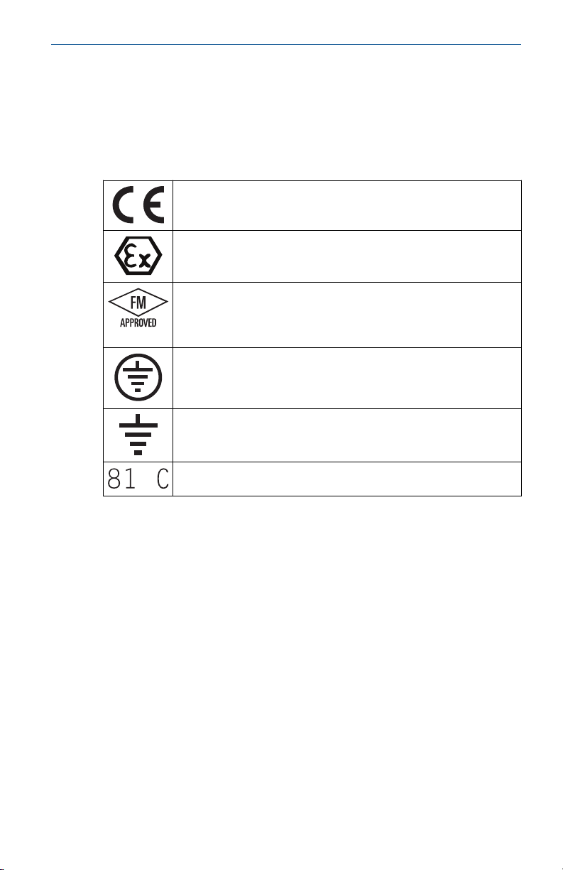
The inclination of the Rosemount 5900S with Parabolic Antenna should not
exceed 1.5 ° towards the center of the tank. For products with high
condensation such as bitumen/asphalt applications, the radar beam should
be directed vertically without any inclination.
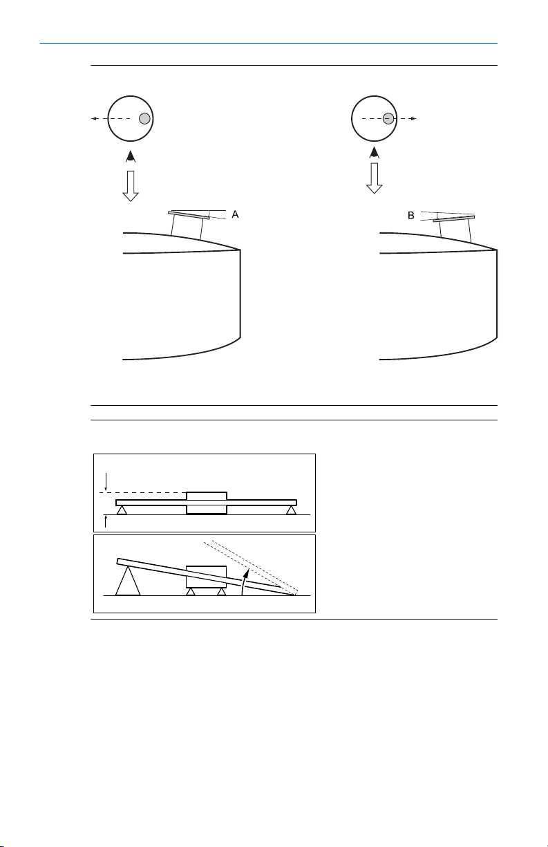
Figure 3-1: Maximum Inclination with Parabolic Antenna
A. Maximum inclination 1.5°
3.2.2 Flange requirements
The tank flange has to meet the following inclination requirements (see
Figure 3-2) in order to allow proper adjustment of the antenna:
• maximum 4.5° away from the tank wall
• maximum of 2° towards the tank wall
• in case the nozzle inclination exceeds the recommended values, you may
use the welded flange ball which can be mounted at a maximum angle of
17°
Quick Start Guide 9
Page 10
60 mm (2.4 in.)
< 17°
Quick Start Guide March 2020
Figure 3-2: Maximum Inclination of Tank Flange
A. 4.5° max
B. 2.0° max
Figure 3-3: Maximum Inclination with Welded Flange
3.2.3 Nozzle and free space requirements
When installing the Rosemount 5900S with parabolic antenna on a Ø 20"
nozzle, consider the following recommendations.
10 Rosemount 5900S Radar Level Gauge
Obstacles (construction bars, pipes larger than Ø 2", etc.) within the 10° wide
radar beam are generally not accepted, as these may result in disturbing
echoes. However, in most cases a smooth tank wall or small objects will not
have any significant influence.
Page 11
C
E
B
F
F
G
A
D
D
March 2020 Quick Start Guide
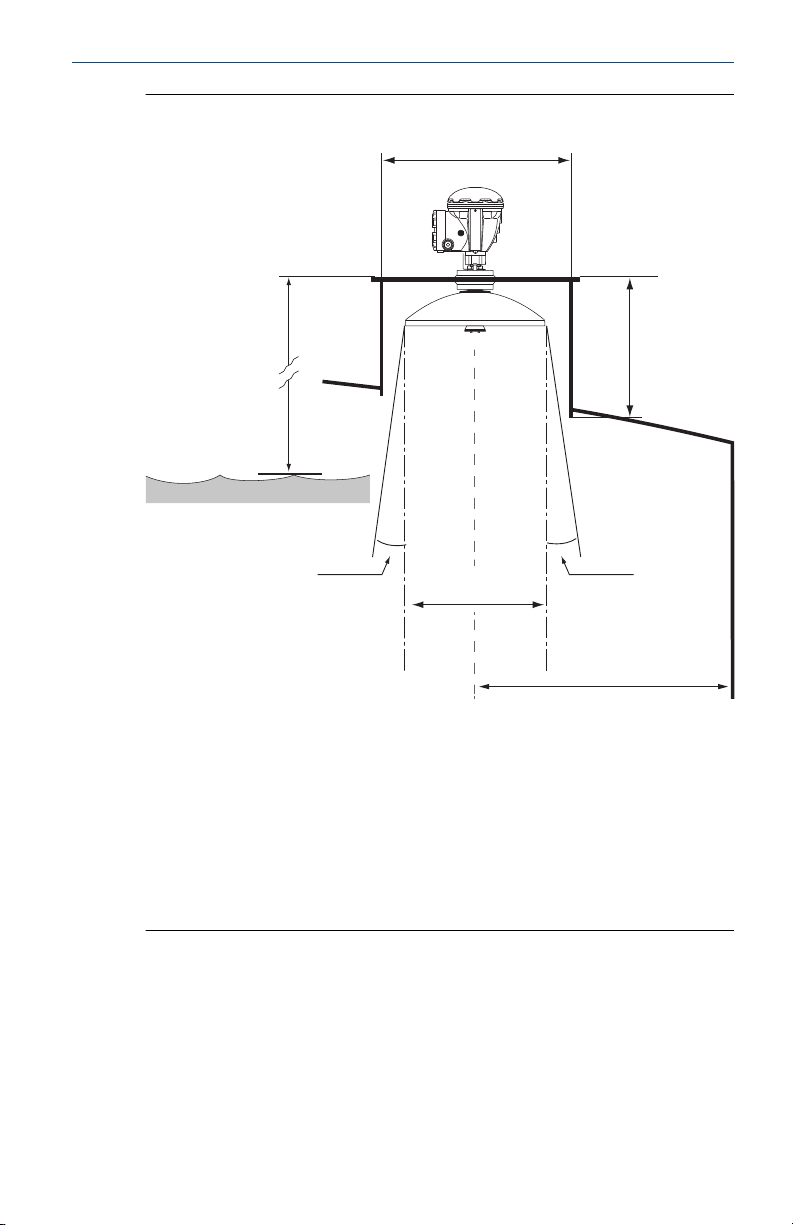
Figure 3-4: Nozzle and Free Space Requirements for Parabolic Antenna
A. Minimum 800 mm (31 in.) for highest accuracy. Minimum 500 mm (20
in.) with reduced accuracy.
B. Recommended height: 400 mm (16 in.). Maximum height: 600 mm (24
in.).
C. Minimum nozzle diameter: 500 mm (20 inch.)
E. Ø 440 mm (17.3 in.)
Vertical plumb line
D.
F. 5° minimum
G. > 800 mm (31.5 in.)
Quick Start Guide 11
Page 12
$
Quick Start Guide March 2020
3.3 Electrical requirements
3.3.1 Cable/conduit entries
The electronics housing has two entries for ½ - 14 NPT. Optional M20×1.5,
minifast and eurofast adapters are also available. The connections must be
made in accordance with local or plant electrical codes.
Make sure that unused ports are properly sealed to prevent moisture or
other contamination from entering the terminal block compartment of the
electronics housing.
Note
Use the enclosed metal plugs to seal unused ports. The plastic plugs
mounted at delivery are not sufficient as seal!
Note
Thread sealing (PTFE) tape or paste on male threads of conduit is required to
provide a water/dust tight conduit seal and to meet the required degree of
ingress protection as well as to enable future removal of the plug/gland.
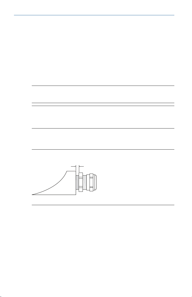
NPT is a standard for tapered threads. Engage the gland with 5 to 6 threads.
Note that there will be a number of threads left outside the housing as
illustrated below.
Figure 3-5: Cable Entry with NPT Threaded Gland
A. The NPT threaded gland leaves a number of threads outside the housing
Ensure that glands for the cable entries meet requirements for IP class 66
and 67.
3.3.2 Grounding
The housing should always be grounded in accordance with national and
local electrical codes. Failure to do so may impair the protection provided by
the equipment. The most effective grounding method is direct connection
to earth ground with minimal impedance.
There are three grounding screw connections provided. Two are located
inside the terminal compartment of the housing and the third is located on
12 Rosemount 5900S Radar Level Gauge
Page 13

March 2020 Quick Start Guide
the housing. The internal ground screws are identified by a ground symbol:
.
Note
Grounding the transmitter via threaded conduit connection may not provide
sufficient ground.
Grounding - FOUNDATION™ Fieldbus
Signal wiring of the fieldbus segment can not be grounded. Grounding out
one of the signal wires may shut down the entire fieldbus segment.
Shield wire ground
To protect the fieldbus segment from noise, grounding techniques for shield
wire usually require a single grounding point for shield wire to avoid creating
a ground loop. The ground point shall be located at the power supply.
The devices designed for “daisy-chain” connection offer an isolated shield
loop-through terminal in order to enable a continuous shield throughout the
Tankbus network.
In order to avoid unintentional grounding points, the cable shield inside the
terminal compartment must be isolated.
3.3.3 Hazardous areas
When the Rosemount 5900S level gauge is installed in hazardous areas, local
regulations and specifications in applicable certificates must be observed.
Certificates for Rosemount Tank Gauging products, such as the Rosemount
5900, are available on Emerson.com/Rosemount Tank Gauging.
3.3.4 Power requirements
The Rosemount 5900S is powered over the intrinsically safe Tankbus by the
Rosemount 2410 Tank Hub. The 2410 feeds the intrinsically safe fieldbus
segment by acting as a FISCO power supply on the Tankbus.
When installed in a FOUNDATION Fieldbus system without a Rosemount 2410
Tank Hub, the Rosemount 5900S is powered by the FF segment.
Quick Start Guide 13
Page 14
Quick Start Guide March 2020
4 Mechanical installation
4.1 Parabolic antenna
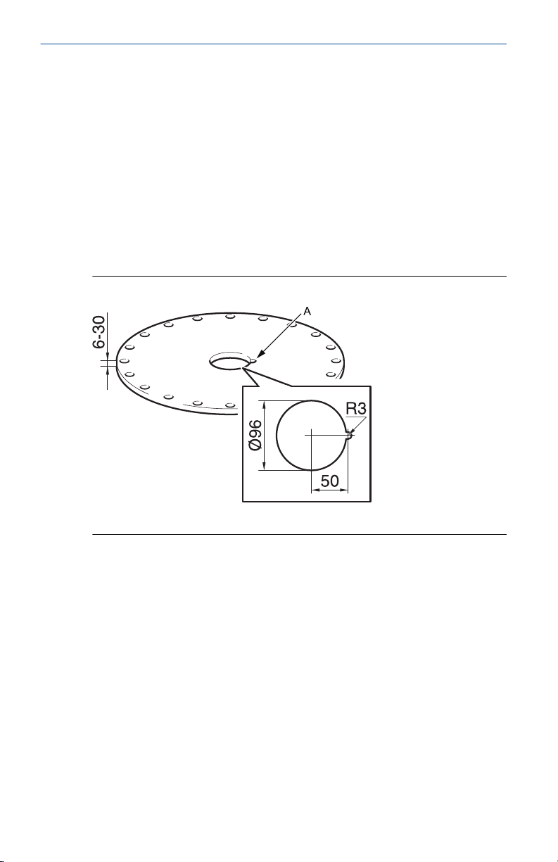
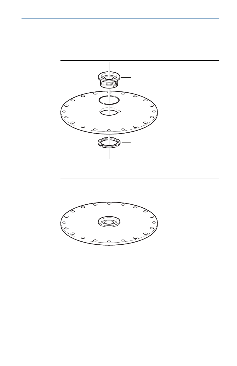
4.1.1 Mounting the clamped Flange Ball
Follow this instruction when installing the clamped Flange Ball on a flange.
Prerequisites
1.
Use a flange of thickness 6 - 30 mm.
Make sure that the diameter of the hole is 96 mm. Make a small
2.
recess at one side of the flange hole.
Figure 4-1: Flange Requirements
A. Recess
14 Rosemount 5900S Radar Level Gauge
Page 15
$
%
March 2020 Quick Start Guide
Procedure
1. Put the O-ring on the flange and insert the Flange Ball into the hole.
Make sure that the guide pin on the side of the Flange Ball fits into
the recess on the flange.
A. Flange Ball
B. Nut
2. Tighten the nut so that the Flange Ball fits tightly to the flange
(torque 50 Nm).
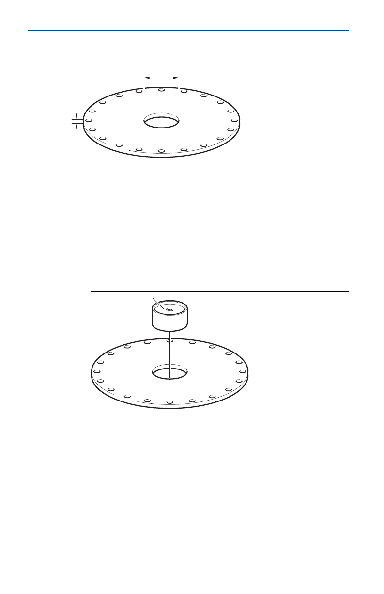
4.1.2 Mounting the welded Flange Ball
Follow this instruction when installing the welded Flange Ball on a flange.
Prerequisites
For horizontal mounting according to requirements in chapter Parabolic
antenna requirements, make sure that the diameter of the hole is 116 ± 2
mm.
Quick Start Guide 15
Page 16
$
%
%
$
Quick Start Guide March 2020
Figure 4-2: Flange Requirements
A. 116±2 mm
B. 6-38 mm
In case the flange requirements in chapter Parabolic antenna requirements
are not met, the hole needs to be machined to an oval shape prepared for
inclined welding of the Flange Ball.
Procedure
1.
Let the protection plates remain on the Flange Ball until welding is
finished. These plates protect the surface of the Flange Ball from
welding sparks.
A. Protection plate
B. Flange Ball
16 Rosemount 5900S Radar Level Gauge
Page 17
$
60 mm (2.4 in.)
< 17°
March 2020 Quick Start Guide
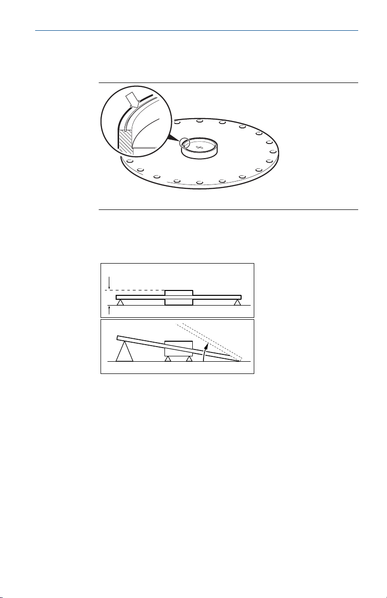
2. Make sure that the Flange Ball is mounted in such a way that the
grove is directed upwards when the flange is mounted on the tank
nozzle.
A. Groove
3. If the tank flange is inclined, make sure that the Flange Ball is welded
so that the Flange Ball is horizontal when it is mounted on the tank.
The tank flange inclination should not exceed 17 degrees.
Quick Start Guide 17
Page 18

$
$
Quick Start Guide March 2020
4. Remove the protection plates when the Flange Ball is welded to the
flange.
A. Protection plate
4.1.3 Mounting the parabolic antenna
This section describes how to install the Rosemount 5900S with Parabolic
antenna.
Follow this instruction to install the Parabolic antenna and transmitter head
assembly on a tank.
Prerequisites
• See Parabolic antenna requirements for considerations before installing
the gauge on the tank.
• Check that all parts and tools are available before carrying them up to
the tank top.
18 Rosemount 5900S Radar Level Gauge
Page 19

$
%
&
March 2020 Quick Start Guide
Procedure
1. Fit the Parabolic Reflector onto the Antenna Feeder and tighten the
five M5 screws.
A. M5x5
B. Parabolic Reflector
C. Antenna Feeder
2. Check that all parts are properly mounted.
Quick Start Guide 19
Page 20

&
$
%
'
Quick Start Guide March 2020
3. Put the two O-rings in the grooves on the upper surface of the Flange
Ball.
A. 2 O-rings
B. Grooves
C. Flange Ball
D.
Flange
20 Rosemount 5900S Radar Level Gauge
Page 21

$
%
&
'
(
*
+
)
March 2020 Quick Start Guide
4. Turn the flange around and insert the Antenna Waveguide into the
flange hole.
A. Nut
B. Tab Washer
C. Antenna label plate
Finger Nut
D.
E. Washer Ball
F. Stop Washer
G. Flange
H. Antenna Waveguide
5. Mount the washers and nuts.
Note that the purpose of the Stop Washer is to prevent the antenna
from falling down into the tank. Therefore it fits tightly to the
Antenna Waveguide.
Quick Start Guide 21
Page 22

$
%
C
B
A
D
Quick Start Guide March 2020
6. Tighten the finger nut and the upper nut by hand.
A. Finger Nut
B. Upper Nut
7. Place the antenna and flange assembly on the tank nozzle and
tighten the flange screws.
A. Antenna Waveguide
B. Flange
C. Antenna
D.
Nozzle
22 Rosemount 5900S Radar Level Gauge
Page 23

&
%
$
March 2020 Quick Start Guide
8. Put the level gauge on the Antenna Waveguide. Ensure that the
guide pin inside the transmitter head fits into the groove on the
Antenna Waveguide.
A. Nut
B. Antenna Waveguide
C. Finger Nut
9. Tighten the nut that connects the transmitter head to the antenna.
10.
Loosen the finger nut slightly.
Quick Start Guide 23
Page 24

$
&
%
r
r
Quick Start Guide March 2020
11. Align the level gauge by using the cross hairs on top of the
transmitter head.
In case the weather protection hood is attached, the gauge can be
aligned by using a line of sight along the screws on top of the head.
A. Tank
B. Tank center
C. Line of sight
12. Ensure that the gauge is directed at an angle of 45° to the line of sight
from the center of the tank to the wall.
24 Rosemount 5900S Radar Level Gauge
Page 25

March 2020 Quick Start Guide
13. Use the marks on the Washer Ball to adjust the gauge so the antenna
is inclined roughly 1.5° towards the center of the tank.
Note
For products with high condensation, such as bitumen, the gauge
should be mounted with 0° inclination in order to achieve maximum
signal strength.
A. Marks
B. Plumb line
C. Tank center
D. Incline antenna 1.5° towards tank center
14. Tighten the finger nut.
Quick Start Guide 25
Page 26

Quick Start Guide March 2020
15. You may use a level (optional) to verify correct inclination of 1.5°
towards the tank center. Ensure that the level is put on a flat and
steady surface on top of the transmitter head. If needed, loosen the
finger nut and adjust the gauge.
Note
Make sure the air bubble touches, but doesn't overlap the 1.5° mark.
A. Finger Nut
16. Tighten the finger nut firmly.
26 Rosemount 5900S Radar Level Gauge
Page 27

March 2020 Quick Start Guide
17. In case the Weather Protection Hood was removed, put it back on
top of the transmitter head and tighten the screw.
A. Weather Protection Hood
B. Finger Nut
Quick Start Guide 27
Page 28

Quick Start Guide March 2020
18. Tighten the upper nut to lock the finger nut (you may temporarily
remove the transmitter head to make room for tools if needed), and
secure by folding the tab washer over the nut.
A. Upper Nut
19. Wire the gauge and configure by using the RosemountTankMaster
WinSetup software (see the Rosemount Tank Gauging System
Configuration Manual).
28 Rosemount 5900S Radar Level Gauge
Page 29

March 2020 Quick Start Guide
5 Electrical installation
5.1 Wiring
To connect the Rosemount 5900S level gauge:
Procedure
Ensure that the power supply is switched off.
1.
2. Remove the cover on the terminal compartment.
3. Run the wires through the appropriate cable gland/conduits. Install
cables with a drip loop in such a way that the lower part of the loop is
under the cable/conduit entry.
4.
Connect wires as described in Terminal blocks.
5. Ensure that the positive lead is connected to the terminal marked FB
+ and the negative lead to the terminal marked FB-.
6. Use metal plugs to seal unused ports.
The cover on the terminal compartment should be tightened to
7.
mechanical stop (metal to metal). Make sure the cover is fully
engaged to meet explosion-proof requirements and to prevent water
from entering the terminal compartment.
8. Tighten the cable gland/conduit. Note that adapters are required for
M20 glands.
Note
Ensure that O-rings and seats are in good condition prior to
mounting the cover in order to maintain the specified level of ingress
protection. The same requirements apply for cable inlets and outlets
(or plugs). Cables must be properly attached to the cable glands.
Quick Start Guide 29
Page 30

AA
B
D
E
C
F
Quick Start Guide March 2020
Figure 5-1: Terminal Compartment
A. Cable glands
B. Internal Ground screws
C. Terminals for signal and power supply
Locking screw (Unscrew to lock)
D.
E. External Ground screw
F. Cover
30 Rosemount 5900S Radar Level Gauge
Page 31

B
A A
C
+
-
+
-
C
March 2020 Quick Start Guide
5.2 Terminal blocks
Figure 5-2: Rosemount 5900S Terminal Compartment
A. Test terminals
B. Ground terminals, internal
C. Field bus
Table 5-1: Terminal Block Connections for the Rosemount 5900S
Connection Description
X1: Tankbus in Intrinsically safe Tankbus input, power and communication
X2: Terminate on The integrated line terminator is connected over the Tankbus
X3: Shield loop
through
X4: Tankbus out Tankbus output connected to X1 for optional daisy-chain
Test terminals Test terminals for temporary connection of a Field
(spur in FOUNDATION Fieldbus system)
when a jumper is placed in the terminal block
Cable shield daisy-chain connector (not grounded)
connection to other devices
Communicator
Quick Start Guide 31
Page 32

A
FB +
FB -
B
C
Quick Start Guide March 2020
5.2.1 Terminal block two-in-one single bus
Figure 5-3: Terminal Compartment 2-in-1 Version
A. Test terminals
B. Ground terminals, internal
C. Jumpers between X3 and X4
FB. Field Bus
Table 5-2: Rosemount 5900S Two-in-One with Single Tankbus
Connection Two-in-One / Single tankbus
X1: Primary
Tankbus in
X2: Primary
Terminate on
X3: Primary
Tankbus out
X4: Secondary
Tankbus in
Test terminals Test terminals for temporary connection of a field
Intrinsically safe Tankbus input, power and communication
Termination for primary tankbus. The integrated line
terminator is connected over the Tankbus when a jumper is
placed in the terminal block.
Jumpers between X3 and X4
communicator
32 Rosemount 5900S Radar Level Gauge
Page 33

March 2020 Quick Start Guide
6 Configuration
6.1 Tank geometry parabolic antenna
The following parameters are used for tank geometry configuration of a
Rosemount 5900S Radar Level Gauge with parabolic antenna:
Figure 6-1: Tank Geometry Parameters for the Rosemount 5900S
A. Tank Reference Point
B. Tank Ullage
C. Minimum Level Offset (C); distance from Zero Level to tank bottom
Ullage
D.
E. Product level
F. Zero Level (Dipping Datum Point)
G. Gauge Reference Distance (G); distance from Tank Reference Point to the
Gauge Reference Point
H. Gauge Reference Point
I. Hold Off Distance; defines how close to the Gauge Reference Point levels
can be measured
J. Measuring range
K. Tank Reference Height (R); distance from Tank Reference Point to Zero
level
Quick Start Guide 33
Page 34

1. Communication
2. Preferences
3. Rosemount 2460 System Hub
4. Rosemount 2410 Tank Hub
6. Tanks
7. Calibration
5. Rosemount 5900 and other field
devices
Rosemount 2460
Rosemount TankMaster
Rosemount 2410
Rosemount 2230
Rosemount 2240S
Rosemount 5900S
Quick Start Guide March 2020
6.2 Configuration using WinSetup
A Rosemount 5900S is typically installed by using the installation wizard in
TankMaster WinSetup configuration software. It is recommended that the
Rosemount 2460 System Hub and Rosemount 2410 Tank Hub are installed
and configured prior to field devices such as level gauges, temperature, and
pressure transmitters as illustrated in Figure 6-2.
It is important that the tank database of the Rosemount 2410 Tank Hub has
all the information that is stored in the Rosemount 2460 System Hub’s
database. This ensures that new devices are mapped to the correct tanks,
and that all tank variables are properly updated and distributed.
See the System Configuration Manual (Document no. 00809-0300-5100) for
more information.
Figure 6-2: Installation Procedure
34 Rosemount 5900S Radar Level Gauge
Page 35

March 2020 Quick Start Guide
Configuration in TankMaster WinSetup
A field device such as the Rosemount 5900S level gauge is typically installed
as part of the Rosemount 2410 Tank Hub installation procedure in
TankMaster.
Once the gauge is installed, click the Properties option to configure the
device.
Figure 6-3: TankMaster WinSetup Workspace with Installed Devices
Quick Start Guide 35
Page 36

A
B
D
E
F
G
H
C
Quick Start Guide March 2020
The Properties window includes tabs for basic and advanced configuration.
Figure 6-4: Properties Window
A. Tabs for basic and advanced configuration
B. Tank hub that the radar level gauge is connected to
C. Position in the tank hub's database
Communication channel
D.
E. Modbus address
F. Unit Id
G. Application and boot firmware versions
H. Red icon means that the device is not configured
See the System Configuration Manual (Document no. 00809-0300-5100) for
more information.
36 Rosemount 5900S Radar Level Gauge
Page 37

March 2020 Quick Start Guide
Basic configuration
The Properties window has a number of tabs that lets you configure the
device for optimum performance. The Communication, Antenna, and
Geometry tabs cover basic configuration of the Rosemount 5900S.
Figure 6-5: Antenna Configuration
Figure 6-6: Tank Geometry Configuration
Quick Start Guide 37
Page 38

Quick Start Guide March 2020
A Product Certifications
Rev 7.15
A.1 European directive information
The most recent revision of the EU Declaration of Conformity can be found
at Emerson.com/Rosemount.
A.2 Ordinary Location Certification
As standard, the transmitter has been examined and tested to determine
that the design meets the basic electrical, mechanical, and fire protection
requirements by a nationally recognized test laboratory (NRTL) as accredited
by the Federal Occupational Safety and Health Administration (OSHA).
Complies with FM 3810:2005 and CSA: C22.2 No. 1010.1.
A.3 Telecommunication compliance
A.3.1 FCC
This device complies with Part 15C of the FCC Rules. Operation is subject to
the following two conditions: (1) This device may not cause interference,
and (2) this device must accept any interference received, including
interference that may cause undesired operation.
Certificate: K8C5900
A.3.2 IC
This device complies with RSS210-7.
Certificate: 2827A-5900
A.3.3 Radio Equipment Directive (RED)
This device complies with ETSI EN 302 372 and EN 62479. EU directive
2014/53/EU. The device shall be installed according to requrements ETSI EN
302372.
A.4 CE-mark
The product complies with applicable EU directives (EMC, ATEX, LVD, and
RED). Based on the low emitted effects from the gauges (below 0.1 mW)
compared to limits given by the Rec. 1999/519/EC, no additional measures
are needed.
38 Rosemount 5900S Radar Level Gauge
Page 39

March 2020 Quick Start Guide
A.5 Installing Equipment in North America
The US National Electrical Code® (NEC) and the Canadian Electrical Code
(CEC) permit the use of Division marked equipment in Zones and Zone
marked equipment in Divisions.
The markings must be suitable for the area classification, gas, and
temperature class. This information is clearly defined in the respective
codes.
A.6 North America
A.6.1 I5 USA Intrinsic Safety
Certificate
Standards
Markings
Ui
Entity parameters 30 V 300 mA 1.3 W 1.1 nF 1.5 µH
FISCO parameters 17.5V 380 mA 5.32 W 1.1 nF 1.5 µH
Specific Conditions for Safe Use (X):
1. The enclosure contains aluminum and is considered to present a
potential risk of ignition by impact or friction. When installed as EPL
Ga, care must be taken during installation and use to prevent impact
or friction.
FM 17US0030X
FM Class 3600:2018, FM Class 3610:2018, FM Class
3810:2005, ANSI/ISA 61010-1:2004, ANSI/NEMA
250:2003, ANSI/IEC 60529:2004, ANSI/UL
60079-0:2013 Ed 6, ANSI/UL 60079-11:2014 Ed 6.3,
ANSI/UL 60079-26:2017 Ed 3
IS/I,II,III/1/ABCDEFG/T4
DIP/II,III/1/EFG/T5
CL 1 ZN 0 AEx ia IIC T4 Ga
CL 1 ZN 0/1 AEx ib IIC T4 Ga/Gb
Ta = -50°C to 80°C - 9240040-917;
Type 4X; IP66; IP67
Ii (lmax) Pi Ci Li
(Vmax)
2. Non-metallic surfaces and the surface of the painted housing may,
under certain extreme conditions, generate an ignition-capable level
of electrostatic. Appropriate measures must be taken to prevent
electrostatic discharge.
3. Using the box provided on the nameplate, the User shall
permanently mark the type of protection chosen for the specific
Quick Start Guide 39
Page 40

Quick Start Guide March 2020
installation. Once the type of protection has been marked it shall not
be changed.
4.
When installed as Ex ib Ga/Gb, the partition wall materials separating
EPL Ga from EPL Gb are constructed of different materials depending
on the antenna option. Please refer to Control Drawing
D9240040-917 for the material type of each antenna. The material
shall not be subject to environmental conditions which might
adversely affect the partition wall.
Maximum Process Temperatures are as follows:
5.
When option n=Tank
Seal
PV or QV Viton -15°C to +180°C
PK, FK, HK or QK Kalrez -20°C to +230°C
PE or QE EPDM -40°C to +110°C
PB or QB BUNA-N -35°C to +90°C
PM, FF, HH or QM FVMQ -60°C to +155°C
PF or QF FEP -60°C to +180°C
A.6.2 I6 Canada Intrinsic Safety
Certificate
Standards
Markings
FM17CA0016X
CSA-C22.2 No. 25-2017
CSA-C22.2 No. 94-M91:1991 (R2011)
CSA-C22.2 No. 1010-1:2004 (R2009)
CSA-C22.2 No. 60529:2016
CSA-C22.2 No. 60079-0:2015
CSA-C22.2 No. 60079-11:2014
CSA-C22.2 No. 60079-26:2016
IS/I,II,III/1/ABCDEFG/T4
Ex ia IIC T4 Ga
Ex ib IIC T4 Ga/Gb
DIP/II,III/1/EFG/T5
Ta = -50°C to 80°C
9240040-917
Type 4X; IP66; IP67
O-ring Type Min/Max Process
Temperature Range
40 Rosemount 5900S Radar Level Gauge
Page 41

March 2020 Quick Start Guide
Ui
(Vmax)
Entity parameters 30 V 300 mA 1.3 W 1.1 nF 1.5 µH
FISCO parameters 17.5V 380 mA 5.32 W 1.1 nF 1.5 µH
Ii (lmax) Pi Ci Li
Specific Conditions for Safe Use (X):
1. The enclosure contains aluminum and is considered to present a
potential risk of ignition by impact or friction. When installed as EPL
Ga, care must be taken during installation and use to prevent impact
or friction.
2. Non-metallic surfaces and the surface of the painted housing may,
under certain extreme conditions, generate an ignition-capable level
of electrostatic. Appropriate measures must be taken to prevent
electrostatic discharge.
3. Using the box provided on the nameplate, the User shall
permanently mark the type of protection chosen for the specific
installation. Once the type of protection has been marked it shall not
be changed.
4. When installed as Ex ib Ga/Gb, the partition wall materials separating
EPL Ga from EPL Gb are constructed of different materials depending
on the antenna option. Please refer to Control Drawing
D9240040-917 for the material type of each antenna. The material
shall not be subject to environmental conditions which might
adversely affect the partition wall.
5. Maximum Process Temperatures are as follows:
When option n=Tank
Seal
PV or QV Viton -15°C to +180°C
PK, FK, HK or QK Kalrez -20°C to +230°C
PE or QE EPDM -40°C to +110°C
PB or QB BUNA-N -35°C to +90°C
PM, FF, HH or QM FVMQ -60°C to +155°C
PF or QF FEP -60°C to +180°C
O-ring Type Min/Max Process
Temperature Range
A.7 Europe
A.7.1 I1 ATEX Intrinsic Safety
Certificate
Quick Start Guide 41
FM09ATEX0057X
Page 42

Quick Start Guide March 2020
Standards
EN IEC 60079-0:2018, EN 60079-11:2012, EN
60079-26:2015, EN 60529:1991+A1(2000)+A2(2013)
Markings
II 1 G Ex ia IIC T4 Ga
II 1/2 G Ex ib IIC T4 Ga/Gb
Ta = -50°C to 80°C; IP66, IP67
Ui
(Vmax)
Entity parameters 30 V 300 mA 1.3 W 1.1 nF 1.5 µH
FISCO parameters 17.5V 380 mA 5.32 W 1.1 nF 1.5 µH
Ii (lmax) Pi Ci Li
Specific Conditions for Safe Use (X):
1. The enclosure contains aluminum and is considered to present a
potential risk of ignition by impact or friction. When installed as EPL
Ga, care must be taken during installation and use to prevent impact
or friction.
2. Non-metallic surfaces and the surface of the painted housing may,
under certain extreme conditions, generate an ignition-capable level
of electrostatic. Appropriate measures must be taken to prevent
electrostatic discharge.
3.
Using the box provided on the nameplate, the User shall
permanently mark the type of protection chosen for the specific
installation. Once the type of protection has been marked it shall not
be changed.
4. When installed as Ex ib Ga/Gb, the partition wall materials separating
EPL Ga from EPL Gb are constructed of different materials depending
on the antenna option. Please refer to Control Drawing
D9240040-917 for the material type of each antenna. The material
shall not be subject to environmental conditions which might
adversely affect the partition wall.
5. Maximum Process Temperatures are as follows:
When option n=Tank
Seal
PV or QV Viton -15°C to +180°C
PK, FK, HK or QK Kalrez -20°C to +230°C
PE or QE EPDM -40°C to +110°C
PB or QB BUNA-N -35°C to +90°C
42 Rosemount 5900S Radar Level Gauge
O-ring Type Min/Max Process
Temperature Range
Page 43

March 2020 Quick Start Guide
When option n=Tank
Seal
PM, FF, HH or QM FVMQ -60°C to +155°C
PF or QF FEP -60°C to +180°C
A.8 International
A.8.1 I7 IECEx Intrinsic Safety
Certificate
Standards
Markings
Ui
Entity parameters 30 V 300 mA 1.3 W 1.1 nF 1.5 µH
FISCO parameters 17.5V 380 mA 5.32 W 1.1 nF 1.5 µH
Specific Conditions for Safe Use (X):
1. The enclosure contains aluminum and is considered to present a
potential risk of ignition by impact or friction. When installed as EPL
Ga, care must be taken during installation and use to prevent impact
or friction.
IECEx FMG 09.0009X
IEC 60079-0:2017, IEC 60079-11:2011, IEC
60079-26:2014
Ex ia IIC T4 Ga
Ex ib IIC T4 Ga/Gb
Ta = -50°C to +80°C; IP66, IP67
(Vmax)
O-ring Type Min/Max Process
Temperature Range
Ii (lmax) Pi Ci Li
2. Non-metallic surfaces and the surface of the painted housing may,
under certain extreme conditions, generate an ignition-capable level
of electrostatic. Appropriate measures must be taken to prevent
electrostatic discharge.
3. Using the box provided on the nameplate, the User shall
permanently mark the type of protection chosen for the specific
installation. Once the type of protection has been marked it shall not
be changed.
4. When installed as Ex ib Ga/Gb, the partition wall materials separating
EPL Ga from EPL Gb are constructed of different materials depending
on the antenna option. Please refer to Control Drawing
D9240040-917 for the material type of each antenna. The material
shall not be subject to environmental conditions which might
adversely affect the partition wall.
Quick Start Guide 43
Page 44

Quick Start Guide March 2020
5. Maximum Process Temperatures are as follows:
When option n=Tank
Seal
PV or QV Viton -15°C to +180°C
PK, FK, HK or QK Kalrez -20°C to +230°C
PE or QE EPDM -40°C to +110°C
PB or QB BUNA-N -35°C to +90°C
PM, FF, HH or QM FVMQ -60°C to +155°C
PF or QF FEP -60°C to +180°C
A.9 Brazil
A.9.1 I2 INMETRO Intrinsic Safety
Certificate
Standards
Markings
Ui
Entity parameters 30 V 300 mA 1.3 W 1.1 nF 1.5 µH
FISCO parameters 17.5V 380 mA 5.32 W 1.1 nF 1.5 µH
UL-BR 17.0982X
ABNT NBR IEC 60079-0:2013, 60079-11:2013,
60079-26:2016
Ex ia IIC T4 Ga/Gb
Tamb: -50 °C to + 80 °C
IP66/IP67
(Vmax)
O-ring Type Min/Max Process
Temperature Range
Ii (lmax) Pi Ci Li
Special Conditions for Safe Use (X):
1. See certificate for special conditions.
A.10 China
A.10.1
44 Rosemount 5900S Radar Level Gauge
I3 China Intrinsic Safety
Certificate
Standards
Markings
GYJ16.1251X
GB 3836.1 - 2010, GB 3836.4 - 2010, GB 3836.20 - 2010
Ex ia IIC T4 Ga
Page 45

March 2020 Quick Start Guide
Ui
(Vmax)
Entity parameters 30 V 300 mA 1.3 W 1.1 nF 1.5 µH
FISCO parameters 17.5V 380 mA 5.32 W 1.1 nF 1.5 µH
Ii (lmax) Pi Ci Li
Special Conditions for Safe Use (X):
1. See certificate for special conditions.
A.11 Technical Regulations Customs Union (EAC)
A.11.1 IM EAC Intrinsic Safety
Certificate
Markings
Ui
Entity parameters 30 V 300 mA 1.3 W 1.1 nF 1.5 µH
FISCO parameters 17.5V 380 mA 5.32 W 1.1 nF 1.5 µH
Special Conditions for Safe Use (X):
1. See certificate for special conditions.
RU C-SE.AA87.B.00346
Ga/Gb Ex ia IIC T4 X
Tamb: -50 °C to + 80 °C
IP66/IP67
Ii (lmax) Pi Ci Li
(Vmax)
A.12 Japan
A.12.1 I4 Japan Intrinsic Safety
Certificate
Markings
Ui
Entity parameters 30 V 300 mA 1.3 W 1.1 nF 1.5 µH
FISCO parameters 17.5V 380 mA 5.32 W 1.1 nF 1.5 µH
Special Conditions for Safe Use (X):
1. See certificate for special conditions.
Quick Start Guide 45
CML 17JPN2301X
Ex ia IIC T4 Ga/Gb
-50 °C ≤ Ta ≤ +80 °C
Ii (lmax) Pi Ci Li
(Vmax)
Page 46

Quick Start Guide March 2020
A.13 Republic of Korea
A.13.1 IP Korea Intrinsic Safety
Certificate
Markings
Ui
Entity parameters 30 V 300 mA 1.3 W 1.1 nF 1.5 µH
FISCO parameters 17.5V 380 mA 5.32 W 1.1 nF 1.5 µH
Special Conditions for Safe Use (X):
1. See certificate for special conditions.
14-KB4BO-0573X
Ex ia IIC T4 Ga/Gb
(-50 °C ≤ Ta ≤ +80 °C)
Ii (lmax) Pi Ci Li
(Vmax)
A.14 Additional certifications
A.14.1 Functional Safety Certification (SIS)
3 Functional Safety
Certificate
Standards
S Functional Safety
Certificate
Standards
Certificate
Standards
ROS 1312032 C001
SIL 3 2-in-1 (1oo2) option (SIS-relays)
IEC 61508:2010 Parts 1-7
ROS 1312032 C004
SIL 2 1-in-1 (1oo1) option, with 4-20mA or K1/K2 relay
IEC 61508:2010 Parts 1-7
ROS 1312032 C005
SIL 2 2-in-1 (1oo1) option, with 4-20mA or K1/K2 relay
IEC 61508:2010 Parts 1-7
A.14.2 Germany WHG Certification (DIBt)
Certificate
Z-65.16-500
A.14.3 Belgium Overfill Certification (Vlarem)
Certificate
46 Rosemount 5900S Radar Level Gauge
99/H031/13072201
Page 47

March 2020 Quick Start Guide
A.14.4 India Intrinsic Safety
Certificate
Markings
P349859/1
Ex ia IIC Ga/Gb
A.15 Custody Transfer Certifications
Australia Custody Transfer
Certificate
Standards
Belgium Custody Transfer
BMS Certificate
Bulgaria Custody Transfer
Bulgaria Institute of Metrology
China Custody Transfer
CPA Pattern Approval
Certificate
Croatia Custody Transfer
Certificate
No 5/1/7
Regulation 60: National Measurement Regulations 1999
NR. P6.0.014.02-B-16
18.10.5106.1
2012-L134
558-02-01_01-15-2
Czech Republic Custody Transfer
Certificate
Estonia Custody Transfer
Certificate
France Custody Transfer
Certificate
Germany Custody Transfer
Certificate
Quick Start Guide 47
0111-CS-C022-10
TJA 6.13-3_15.09.11
No. LNE-24609
PTB-1.5-4058175
Page 48

Quick Start Guide March 2020
India Custody Transfer
Certificate
IND/13/12/191
Indonesia Custody Transfer
Certificate
DITJEN MIGAS CT approval 26.10.2010
Italy Custody Transfer
Certificate
183349 (Raptor system)
Kazakhstan Custody Transfer
GOST Pattern Approval:
Certificate
KZ.02.02.06177-2018 No.14983 (5900)
KZ.02.02.04018-2014 No.10790 (System)
Malaysia Custody Transfer
Certificate
ATS 09-11
Netherlands Custody Transfer
NMI Certificate
TC7982
Norway Custody Transfer
Certificate
No. N-11-7146
Poland Custody Transfer
Certificate
ZT-7 2013
Portugal Custody Transfer
Certificate
P12_101.12_31
Russia Custody Transfer
GOST Pattern Approval:
Certificate
SE.C.29.639.A No. 66902 (5900)
Serbia Custody Transfer
Certificate
48 Rosemount 5900S Radar Level Gauge
393-7_0-01-2088
Page 49

March 2020 Quick Start Guide
South Africa Custody Transfer
Certificate
Switzerland Custody Transfer
Certificate
OIML Custody Transfer
Certificate
SAEx S11-065
Zulassungszertifikat CH-L-11127-01
R85-2008-SE-11.01
A.16 Product Certifications Rosemount 2051
Extract from Rosemount 2051 Product Certifications Rev: 1.13
A.16.1 North America
IE USA FISCO
Certificate
Standards
Markings
Special Conditions for Safe Use (X):
The Model 2051 transmitter housing contains aluminum and is
1.
considered a potential risk of ignition by impact or friction. Care must
be taken into account during installation and use to prevent impact
and friction.
FM16US0231X
FM Class 3600 – 2011, FM Class 3610 – 2010, FM Class
3611 – 2004, FM Class 3810 – 2005
IS CL I, DIV 1, GP A, B, C, D when connected per
Rosemount drawing 02051-1009 (-50°C ≤ Ta ≤ +60°C);
Type 4x
IF Canada Intrinsic Safety
Certificate
Standards
Markings
Quick Start Guide 49
2041384
CSA Std. C22.2 No. 142 - M1987, CSA Std. C22.2 No.
213 - M1987, CSA Std. C22.2 No. 157 - 92, ANSI/ISA
12.27.01 – 2003, CAN/CSA-E60079-0:07, CAN/CSAE60079-11:02
Intrinsically safe for Class I, Division 1, Groups A, B, C,
and D when connected in accordance with Rosemount
drawing 02051-1008. Ex ia IIC T3C. Single Seal.
Enclosure Type 4X
Page 50

Quick Start Guide March 2020
A.16.2 Europe
IA ATEX FISCO
A.16.3
Certificate
Standards
Markings
Ui Ii Pi Ci Li
FISCO
parameters
Baseefa08ATEX0129X
EN60079-0:2012+A11:2013, EN60079-11:2012
II 1 G Ex ia IIC T4 Ga (-60°C ≤ Ta ≤ +60°C)
17.5V 380 mA 5.32 W 0 µF 0 mH
Special Conditions for Safe Use (X):
1. If the equipment is fitted with an optional 90V transient suppressor,
it is incapable of withstanding the 500V isolation from earth test and
this must be taken into account during installation.
2. The enclosure may be made of aluminum alloy and given a protective
polyurethane paint finish; however care should be taken to protect it
from impact and abrasion when located in Zone 0.
International
IG IECEx FISCO
Certificate
Standards
Markings
IECExBAS08.0045X
IEC60079-0:2011, IEC60079-11:2011
Ex ia IIC T4 Ga (-60°C ≤ Ta ≤ +60°C)
Ui Ii Pi Ci Li
FISCO
parameters
17.5V 380 mA 5.32 W 0 nF 0 µH
Special Conditions for Safe Use (X):
1. If the equipment is fitted with an optional 90V transient suppressor,
it is incapable of withstanding the 500V isolation from earth test and
this must be taken into account during installation.
2. The enclosure may be made of aluminum alloy and given a protective
polyurethane paint finish; however care should be taken to protect it
from impact and abrasion when located in Zone 0.
3.
The equipment contains thin wall diaphragms. The installation,
maintenance and use shall take into account the environmental
conditions to which the diaphragms will be subjected. The
50 Rosemount 5900S Radar Level Gauge
Page 51

March 2020 Quick Start Guide
manufacturer’s instructions for installation and maintenance shall be
followed in detail to assure safety during its expected lifetime.
A.17 Declaration of conformity
Emerson.com/Rosemount
Figure A-1: Rosemount 5900S EU Declaration of Conformity (page 1)
Quick Start Guide 51
Page 52

Quick Start Guide March 2020
Figure A-2: Rosemount 5900S EU Declaration of Conformity (page 2)
52 Rosemount 5900S Radar Level Gauge
Page 53

March 2020 Quick Start Guide
Figure A-3: Rosemount 5900S EU Declaration of Conformity (page 3)
Quick Start Guide 53
Page 54

Quick Start Guide March 2020
A.18 China RoHS
Figure A-4: Rosemount 5900S China RoHS
54 Rosemount 5900S Radar Level Gauge
Page 55

March 2020 Quick Start Guide
Quick Start Guide 55
Page 56

Global Headquarters and Europe
Regional Office Tank Gauging
Emerson Automation Solutions
Box 150
(Visiting address: Layoutvägen 1)
SE-435 23 Mölnlycke
Sweden
+46 31 337 00 00
+46 31 25 30 22
Sales.RTG@Emerson.com
*00825-0100-5900*
Quick Start Guide
00825-0100-5900, Rev. AA
March 2020
North America Regional Office Tank
Gauging
Emerson Automation Solutions
6005 Rogerdale Road
Mail Stop NC 136
Houston, TX 77072, USA
+1 281 988 4000 or +1 800 722 2865
Sales.RTG.HOU@Emerson.com
Latin America Regional Office
Emerson Automation Solutions
1300 Concord Terrace, Suite 400
Sunrise, FL 33323, USA
+1 954 846 5030
+1 954 846 5121
RMTLAContactUS@Emerson.com
Middle East and Africa Regional Office
Emerson Automation Solutions
Emerson FZE
P.O. Box 17033
Jebel Ali Free Zone - South 2
Dubai, United Arab Emirates
+971 4 8118100
+971 4 8865465
RTGMEA.Sales@Emerson.com
Linkedin.com/company/Emerson-
Automation-Solutions
Twitter.com/Rosemount_News
Facebook.com/Rosemount
Youtube.com/user/
RosemountMeasurement
Asia Pacific Regional Office
Emerson Automation Solutions
1 Pandan Crescent
Singapore 128461
+65 6777 8211
+65 6777 0947
Specialist-OneLevel.RMT-
AP@Emerson.com
©
2020 Emerson. All rights reserved.
Emerson Terms and Conditions of Sale are
available upon request. The Emerson logo is a
trademark and service mark of Emerson Electric
Co. Rosemount is a mark of one of the Emerson
family of companies. All other marks are the
property of their respective owners.
 Loading...