

Page 1
Quick Start Guide
00825-0100-4326, Rev 02
August 2020
Rosemount™ 326L Level Transmitter
Page 2

Quick Start Guide August 2020
Contents
Introduction.................................................................................................................................3
Installation................................................................................................................................. 11
Operation...................................................................................................................................25
Troubleshooting and maintenance.............................................................................................44
Setting ranges............................................................................................................................47
Product certifications................................................................................................................. 48
Factory settings..........................................................................................................................49
2 Quick Start Guide
Page 3

August 2020 Quick Start Guide
1 Introduction
The level transmitter continuously detects level of a media and reports the
level of the media in multiple selectable units of measurements and values.
1.1 Safety instructions
Follow these safety guidelines when installing and using the level
transmitter.
CAUTION
• Read this document before installing the level transmitter and keep it for
the life of the level transmitter.
• The level transmitter must be suitable for the corresponding applications
and environmental conditions without any restrictions.
• Use the level transmitter only for its intended purpose.
• Use the level transmitter only with permissible media.
• If you do not adhere to the operating instructions and technical data,
personal injury and/or damage to property might occur.
• The manufacturer assumes no liability or warranty for any consequences
caused by tampering with the product or incorrect use by the operator.
• Installation, electrical connection, set-up, operation and maintenance of
the product must be performed by qualified personnel authorized by the
machine operator.
• Protect units and cables against damage.
1.2
Quick Start Guide 3
Applications
The level transmitter is intended to be used in food and beverage
applications or applications with significant hygienic requirements.
The level transmitter complies with the standard EN 61000-6-4 and is a class
A product. The level transmitter may cause radio interference in domestic
areas. If interference occurs, the user must take appropriate actions.
Note
The level transmitter emits less microwave energy than mobile phones. The
operation of the level transmitter is harmless to human health if used as
intended.
Page 4

Quick Start Guide August 2020
1.2.1 Application area restrictions
Measurements made by the level transmitter can be impacted by the
environment and the type of media it is measuring.
The following media characteristics can cause incorrect measurements:
• Highly absorbing surfaces (foam)
• Intensely bubbling surfaces
• Media which are very inhomogeneous, separate from each other thus
forming separation layers (oil layer on water)
To prevent this, follow these guidelines:
• Check the function by performing an application test.
• Install the level transmitter in a steady environment.
In case of signal loss, the level transmitter displays SEnS and switches the
outputs to a defined state. See Output response in different operating states
for more information.
The level transmitter is not suitable for:
• Bulk materials like plastic granulates and media with a very low dielectric
constant like oils.
• Applications where the probe is subjected to permanent and high
mechanical stress. For example, fast moving viscous medium or fast
flowing medium.
Use the level transmitter preferably with metal tanks. When used with
plastic tanks, deterioration caused by electromagnetic interference might
occur (noise immunity to EN61000-6-2).
4 Quick Start Guide
Page 5
August 2020 Quick Start Guide
1.3 Measuring principle
The level transmitter uses guided wave radar to measure media level. It
emits electromagnetic pulses every nanosecond to measure the level.
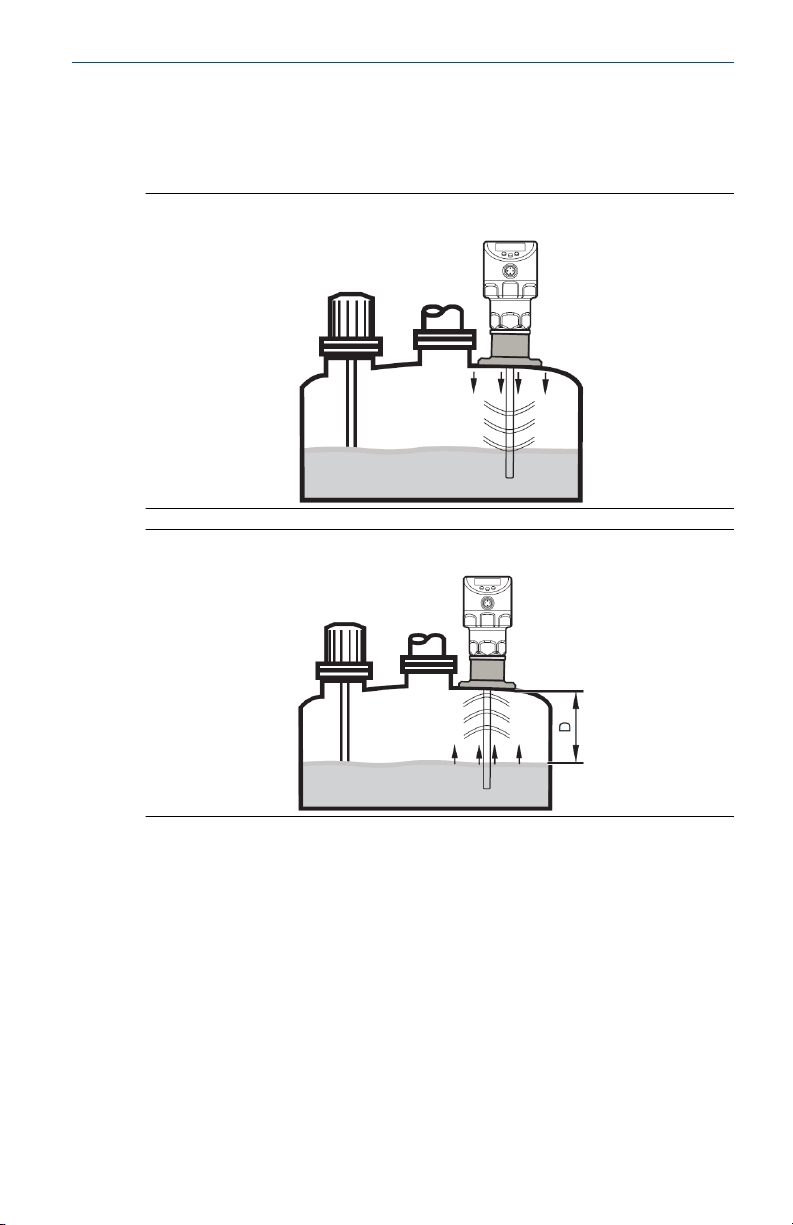
Figure 1-1: Transmitting Pulses
Figure 1-2: Receiving Pulses
The transmitter head transmits pulses that are guided along the probe
towards the media (Figure 1-2). When the pulses hit the media they are
reflected and guided back to the transmitter (Figure 1-2). The time between
transmitting and receiving the pulse determines the traveled distance (D)
and the current level. The reference for distance measurement is the lower
edge of the process connection.
1.3.1 Probes for different tank heights
The height of the probe must be adjusted to accommodate the height of the
tank. Probes at different heights are available to order. The minimum probe
Quick Start Guide 5
Page 6

Quick Start Guide August 2020
length is 1.18 in. (150 mm). The maximum probe length is 78.74 in. (2000
mm).
1.4 Outputs
The level transmitter generates output signals based on the output
parameter settings. Two outputs are available and they can be set
separately.
OUT1
OUT1 provides a switching signal for level limit or IO-Link communication.
See IO-Link for more information.
OUT2
OUT2 can perform one of these functions:
• An analog signal proportional to the level 4 - 20 mA or 20 - 4 mA
• Switching signal for level limit
1.4.1 Fault states
Defined states for each output prepare the output for fault conditions. If the
level transmitter detects a fault or if the signal quality is below a minimum
value, the transmitter outputs change to the defined fault state.
Use FOU1 and FOU2 to configure fault states for the respective outputs.
Fault states for the analog output follow Namur recommendation (NE43).
For more information, see Set response of the outputs in case of fault.
Setting a delay time prevents the level transmitter from erroneously falling
into a fault state. For more information, see Set delay time in case of a fault.
During the delay time, the level transmitter retains the last measured value.
If the measured signal is received again in sufficient strength within the
delay time, the unit continues to work in normal operation. If it is not
received again in sufficient strength within the delay time, the outputs
change to the defined state.
Note
In case of heavy foam build-up or turbulence, create a steady environment
for the level transmitter. For more information, see Minimum distances and
connection piece diameter.
1.5
6 Quick Start Guide
IO-Link
The level transmitter has an IO-Link communication interface which requires
an IO-Link-capable module (IO-Link master) for operation.
The IO-Link interface enables direct access to the process and diagnostic
data and provides the possibility to set the parameters of the unit during
operation.
Page 7

August 2020 Quick Start Guide
Point-to-point connection is possible with a USB adapter cable.
Detailed information about process data structure (IODDs) necessary for the
configuration of the level transmitter, diagnostic information, parameter
addresses, and the necessary information about the required IO-Link
hardware and software can be found at Emerson.com/Rosemount.
1.6 Functions
The level transmitter performs the functions detailed in this section.
1.6.1 Display functions
The level transmitter displays the current level, either in millimeters, inches,
or percentage of the scaled measuring range. The default factory setting is
inches.
For more information on changing the displayed unit of measurement, see
Configure the display.
In the operating mode, you can switch between length display (mm, inch)
and percentage. For more information, see Change display between length
and percentage.
The LEDs indicate the set unit of measurement and the switching status of
the outputs. For more information, see Display elements.
1.6.2 Analog signal
The level transmitter can provide an analog signal proportional to level.
The parameter ou2 defines the output function for the analog output:
• 4-20 mA (ou2 = I)
• 20-4 mA (ou2 = InEG)
For more information, see Set output function for OUT2.
The analog start point ASP2 defines the measured value at which the analog
start value is provided. The analog start value is 4 mA with ou2 = I or 20 mA
with ou2 = InEG. For more information, see Scale analog signal.
The analog end point AEP2 defines the measured value at which the analog
end value is provided. The analog end value is 20 mA with ou2 = I or 4 mA
with ou2 = InEG. For more information, see Scale analog signal.
The minimum distance between ASP2 and AEP2 is 20 percent of the active
zone.
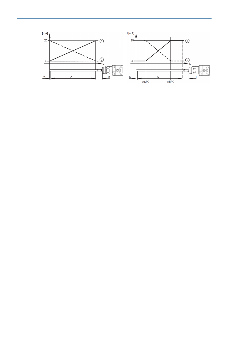
Figure 1-3: Analog signal
The default factory curve of the analog
signal:
Quick Start Guide 7
A scaled measuring range curve of the
analog signal:
Page 8
Quick Start Guide August 2020
L: Level
A: Active zone = L - (I1 + I2)
I1: Inactive zone 1
I2: Inactive zone 2
For more information about the analog output, see Output response in
different operating states.
Take note of the tolerances and accuracy limits during the evaluation of the
analog signal. For more information, see the Product Data Sheet.
1.6.3 Switching functions
When using a switching output (OUT1 or OUT2), the level transmitter
indicates when the level reaches a set limit or that the level is below the
limit.
Select one of the following switching functions for the outputs:
• Hysteresis function/normally open: oux = Hno
• Hysteresis function/normally closed: oux = Hnc
Note
When configuring a switching function, set the set point (SPx) first, then
set the reset point (rPx) with the requested difference.
• Window function/normally open: oux = Fno
• Window function/normally closed: oux = Fnc
1: ou2 = I (factory setting)
2: ou2 = InEG
ASP2: Analog start point
AEP2: Analog end point
Note
The difference between FHx and FLx sets the width of the window. FHx is
the upper value and FLx is the lower value.
8 Quick Start Guide
Page 9
August 2020 Quick Start Guide
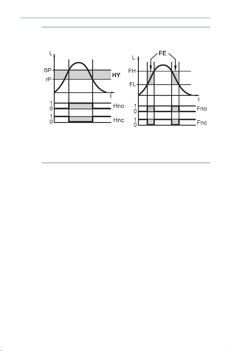
Figure 1-4: Switching function
Hysteresis function Window function
L: Level
HY: Hysteresis
FE: Window
• The adjustable limits (SP and rP) always refer to the lower edge of the
probe.
• The maximum switch-on and switch-off delay for the switching output is
60 seconds. For more information, see Set switch-on delay for switching
outputs and Set switch off delay for switching outputs.
1.6.4 Damping function
If the medium conditions are unsteady, dampen the transmitter response.
The level transmitter uses a filter to smooth the values into a steady curve
when the display and output response is dampened.
You can configure the damping using dAP. For more information, see Set
damping for measured signal.
In the event of a sudden jump in level, dAP indicates the time in seconds for
the output to reach 63 percent of the final value. After five times dAP, the
output should reach 100 percent of the final value.
1.6.5 Simulation functions
To assist in maintenance, reducing interference, or setting up the level
transmitter, simulate error scenarios and levels.
The duration of a simulation can be between one minute and one hour. The
simulation is started manually and runs until the set duration elapses. During
Quick Start Guide 9
Page 10

Quick Start Guide August 2020
the simulation, the outputs respond according to the simulated process
values. For more information, see Simulation.
10 Quick Start Guide
Page 11

August 2020 Quick Start Guide
2 Installation
This section includes instructions for installing and wiring the level
transmitter.
These procedures are required to setup the level transmitter:
1. Installing the level transmitter
2. Wire the transmitter
3. Adjust the probe length
To modify the factory default settings, perform these procedures.
• Set parameters
• Perform a tank adjustment
• Change basic settings
To view the factory default settings, see Factory settings. Test that the level
transmitter is working correctly before using.
2.1 Installation considerations
Follow these installation guidelines to ensure more effective operation of
the level transmitter.
• For more effective level measurement, install the level transmitter
vertically on the top of the tank or pipe.
• To reduce signal interference, perform a tank adjustment (see Tank
adjustment).
• For more effective level measurement, install the level transmitter in
closed, metal tanks or bypass pipes.
— For installation instructions for open tanks, see Installing in an open
tank.
— For installation instructions for plastic containers, see Installing in a
plastic tank.
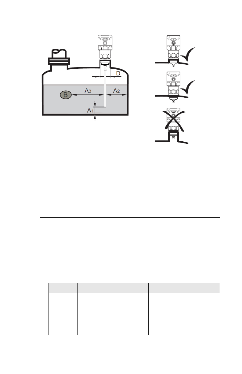
2.1.1 Minimum distances and connection piece diameter
For more effective operation, follow these guidelines for the connection
piece diameter and the distances between the level transmitter and the
tank.
Select a connection piece height that is smaller than the connection piece
diameter.
Quick Start Guide 11
Page 12
Quick Start Guide August 2020
Installation distances with adjustment
A1: 0.39 in (10 mm)
A2: 0.79 in (20 mm)
A3: 0.79 in (20 mm) to tank structures
(B) 1.97 in (50 mm) to other transmitters
type LR
D: ø 1.18 in (30 mm) if installed in a
connection piece
2.1.2 Installation in pipes
If installing the level transmitter in a pipe, the conditions must meet these
requirements.
• Hygienic requirements
• Install only in metal pipes
• The internal diameter of the pipe (d) must meet these requirements:
With adjustment
d ø 1.18 in (30 mm) ø 3.94 in (100 mm) with [MEdI]
Installation distances without
adjustment
A1: 0.39 in (10 mm)
A2: 1.97 in (50 mm)
A3: 1.97 in (50 mm) to tank structures
(B) 1.97 in (50 mm) to other transmitters
type LR
D: No connection piece allowed (see
above image)
Without adjustment
= [HIGH]
ø 7.87 in (250 mm) with [MEdI]
= [MId]
For more information, see Set
to another medium.
12 Quick Start Guide
Page 13
August 2020 Quick Start Guide
Note
Using a centering piece can prevent damage caused by turbulent media by
stabilizing the probe.
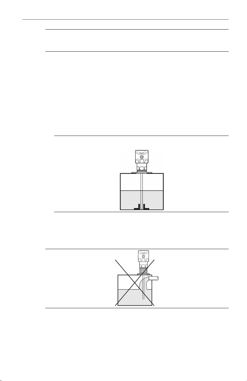
2.1.3 Applications with viscous or fast-flowing media
The installation of the level transmitter must meet the following
requirements if installed in conditions with viscous or fast-flowing media
and/or agitators.
• The probe cannot contact the tank walls or structures.
• Expect an increase in the minimum lateral distances according to probe
length and the lateral deflection.
• If possible, use a sleeve or a similar device to fix the probe at the lower
end so that it is electrically conductive. See Figure 2-1
Figure 2-1: Installation with Viscous or Fast-Flowing Media
• Ensure the correct function is set. (Especially in use with an empty tank)
2.1.4 Fill openings
Do not install the level transmitter near or in contact with a fill opening.
Quick Start Guide 13
Page 14
Quick Start Guide August 2020
2.1.5 Highly polluted medium
If the medium is highly polluted, there is a risk that a bridge forms between
the probe and the tank wall or structures in the tank.
To avoid this, increase minimum distance between the probe and the tank
walls depending on the pollution intensity.
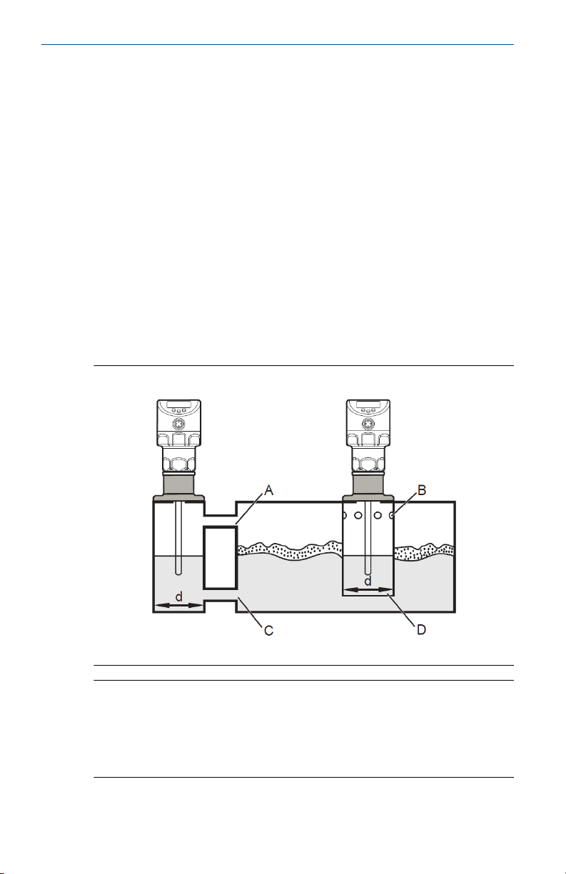
2.1.6 Heavy foam build-up and turbulence
Heavy foam build-up or turbulence in the tank might cause incorrect
measurements.
To avoid this, install the transmitter in a steady area that meets hygienic
requirements.
Examples of how to create a steady environment include:
• Install the level transmitter in a metal bypass or a metal still pipe.
• Separate the level transmitter location with metal sheets or perforated
sheets.
Figure 2-2: Installing in foam build-up and turbulence
d: Minimum diameter (See Installation in pipes)
Note
The upper access to the steady area (A, B) must be above the maximum
level. The lower access (C, D) or the area with perforated sheet must be
below the minimum level. This ensures that neither foam nor turbulence
impact the transmitter zone. To avoid interference from solids in the
medium, use perforated sheets or something similar.
14 Quick Start Guide
Page 15
August 2020 Quick Start Guide
Note
With increased foam build-up set the medium parameter [MEdI] to [MId].
For instructions, see Set to another medium.
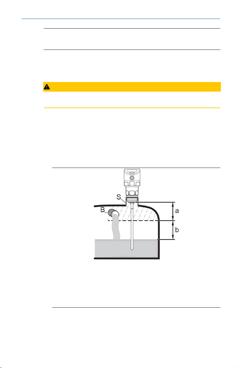
2.1.7 Tank adjustment
Tank adjustment reduces interference and ensures a higher excess gain in
difficult application conditions.
CAUTION
Perform a tank adjustment only after installing the level transmitter.
• When performing a tank adjustment, enter an adjustment distance first.
Starting from the process connection, use the adjustment distance to
compensate for interfering reflections.
• Select an adjustment distance (a) so the level transmitter can detect the
connection piece (S) and structures in the tank (B).
• Observe safety distance (b ≥ 9.84 in (250 mm)) to the level or the probe
end.
a: Minimum adjustment distance is 0.39 in (10 mm); maximum is L - 9.84
in (250 mm)
b: Safety distance to the level or probe end: b ≥ 9.84 in (250 mm)
S: Connection piece
B: Structures in the tank
• For probe lengths L < 10.24 in (260 mm), tank adjustment is not
possible. tREF is then not available. In this case, adhere to all installation
distances in Installation considerations.
Quick Start Guide 15
Page 16
Quick Start Guide August 2020
• If the installation meets all distance guidelines, a tank adjustment is not
necessary.
• If possible, perform the tank adjustment on an empty tank to detect any
possible sources of interference. In this case, select the maximum
adjustment distance (L - 9.84 in or L - 250 mm).
• Tank adjustment information is not saved with IO-Link. After a
replacement, perform a tank adjustment again. For more information on
data storage, see Unit locking and data storage.
2.2 Installing the level transmitter
Follow these instructions to install the level transmitter.
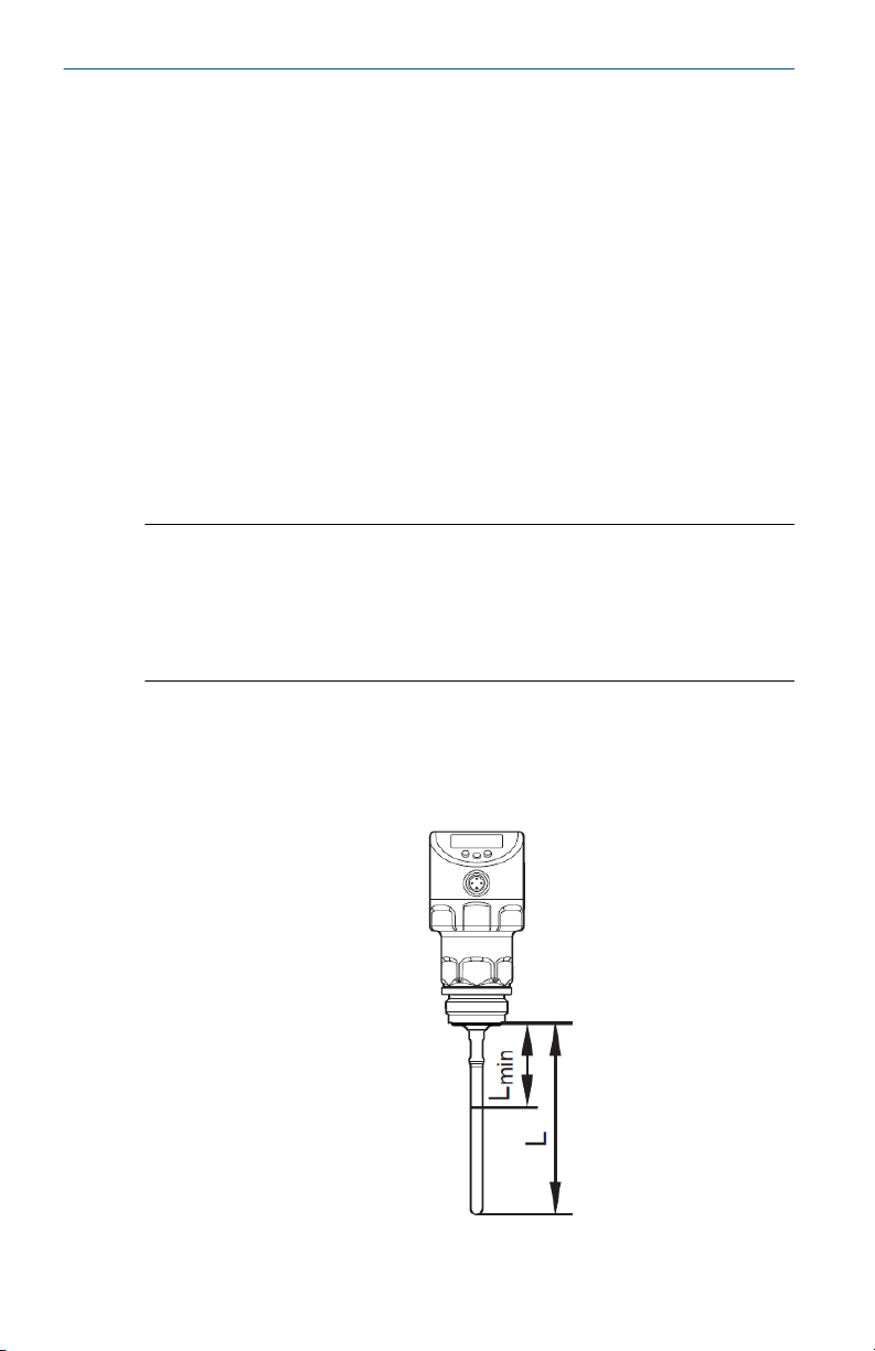
2.2.1 Adjust the probe length
If needed, modify the standard probe length to accommodate the height of
the tank.
Note
• The level transmitter does not support probe lengths less than 5.91 in
(150 mm).
• Tank adjustment is not possible with probe lengths of less than 10.24 in
(260 mm). For more information, see Tank adjustment.
Procedure
1. Screw the probe to the level transmitter.
2. Mark the desired length (L) on the probe. The reference point is the
lower edge of the process connection.
16 Quick Start Guide
Page 17

August 2020 Quick Start Guide
3. Remove the probe from the unit. Do not lose the O-ring between the
probe attachment piece and the probe.
4. Shorten the probe at the mark.
5. Remove all burrs and sharp edges. For hygienic requirements:
Restore the required surface quality. If necessary, polish the probe.
Note
In cases with strong vibrations or moving viscous medium, it may be
necessary to secure the probe connection using screw retaining
compound. In this case, ensure that the compound is harmless
because it might migrate into the medium.
Postrequisites
Reinstall the probe by following the steps in Install the probe.
2.2.2 Install the probe
Install the probe onto the level transmitter to ensure accurate level readings.
For more information, see Measuring principle.
Note
The probe is not included with the level transmitter.
CAUTION
Do not damage the surfaces of the process connection and probe. Use tools
suitable for use with plastic surfaces.
Procedure
1. Remove the protective cover and protective devices from the unit
and the probe.
2. Slip the supplied O-ring onto the probe connection of the unit and
check its position.
3. Screw the probe to the unit and tighten it.
Note
Recommended tightening torque: 4.79 ft/lbs (6.5 Nm).
Quick Start Guide 17
Page 18

Quick Start Guide August 2020
4. Ensure that the O-ring has not moved from its original position.
Replace the O-ring if necessary.
Note
In cases with strong vibrations or moving viscous medium, it might
be necessary to secure the probe connection using screw retaining
compound. In this case, ensure that the compound is harmless
because it might migrate into the medium.
5. If the probe length was modified, measure and record the probe
length.
a) Precisely measure the length of the probe starting from the
lower edge of the process connection.
b) Record the length of the probe. It is needed for setting up the
device parameters.
For more information on setting the length of the probe in the device
parameters, see Enter probe length.
2.2.3 Install the level transmitter
Install the level transmitter using these steps. Take note of the different
process connections.
CAUTION
Consider the potential dangers related to extreme machine and medium
temperatures.
18 Quick Start Guide
Page 19

August 2020 Quick Start Guide
Prerequisites
Note
Before installing or removing the level transmitter, ensure that no pressure is
applied to the system. Also ensure that there is no medium in the tank that
might leak during installation.
The level transmitter can be installed using a mounting or welding adapter
with a sealing ring. The adapters are supplied with an EPDM o-ring. Further
sealing ring materials (FKM) are available. For ordering information, see the
transmitter Product Data Sheet. For installation instructions, refer to the
instructions included with the mounting adapter.
Note
Certain configurations do not allow alignment of the transmitter housing.
With process connections that cannot be aligned, like welding adapters,
take into account the final position of the transmitter housing (readability of
the display, cable entry). Observe marks on adapters. If needed, screw in the
unit and mark the requested alignment.
Procedure
1. Lightly grease the thread of the transmitter using a lubricating paste
suitable and approved for the application.
2. Insert the unit into the process connection.
3. Tighten it using a spanner to a torque of 25.8 ft/lbs (35 Nm).
2.2.4 Installing in an open tank
Follow these guidelines when installing the level transmitter in an open tank.
• Use a metal fixture to install the level transmitter to the side of the open
tank. It serves as a launching plate (R) for the level transmitter. The
minimum size for a square fixture is 5.91 by 5.91 in (150 by 150 mm).
The minimum size for a circular fixture is 5.91 in (150 mm) diameter. For
more information, see Operation with a single probe.
• If possible, mount the level transmitter in the middle of the fixture.
Adhere to the specified installation distances according to Installation
considerations. If necessary, perform a tank adjustment.
Quick Start Guide 19
Page 20

Quick Start Guide August 2020
D1: Minimum 5.91 in (150 mm)
R: Launching plate
2.2.5 Installing in a plastic tank
Follow these guidelines when installing the level transmitter in a plastic tank
or in a metal tank with a plastic lid.
D1: Minimum 5.91 in (150 mm)
R: Launching plate
• The plastic lid must have a drill hole with a minimum diameter of 5.91 in
(150 mm).
• Use a metal flange plate or launching plate (R) that sufficiently covers the
drill hole. For more information, see Operation with a single probe.
• Ensure that the distance between the probe and the tank wall is at least
3.15 in (80 mm). Adhere to the installation instructions in Installation
considerations. If necessary, perform a tank adjustment.
20 Quick Start Guide
Page 21

August 2020 Quick Start Guide
CAUTION
When installed in plastic tanks, there may be deterioration caused by
electromagnetic interference from other devices. Follow these guidelines to
avoid deterioration:
• Apply a metal foil to the outside of the tank.
• Apply a shielding screen between the level transmitter and other
electronic units.
• Install in a metal pipe only if hygienic requirements are met. For more
information, see Installation considerations.
2.2.6 Installing with 3-A® standards
The level transmitter is authorized to display the 3-A symbol. Follow these
guidelines to ensure 3-A compliance when installing the level transmitter.
• Ensure that the transmitter is installed according to 3-A standards.
• Use the level transmitter only with 3-A certified adapters marked with
the 3-A symbol.
• The process connection must have a self-draining leakage port. 3-A
certified adapters all have self-draining leakage ports.
• Choose an installation position where the probe and process connection
can be cleaned with a spray ball.
Note
According to 3-A standards, special regulations apply for cleaning and
maintenance. For more information, see Cleaning and maintenance in 3-A
applications. Not suitable for systems which must meet the criteria of
paragraph E1.2 / 63-03 of the 3-A standard 63-03.
®
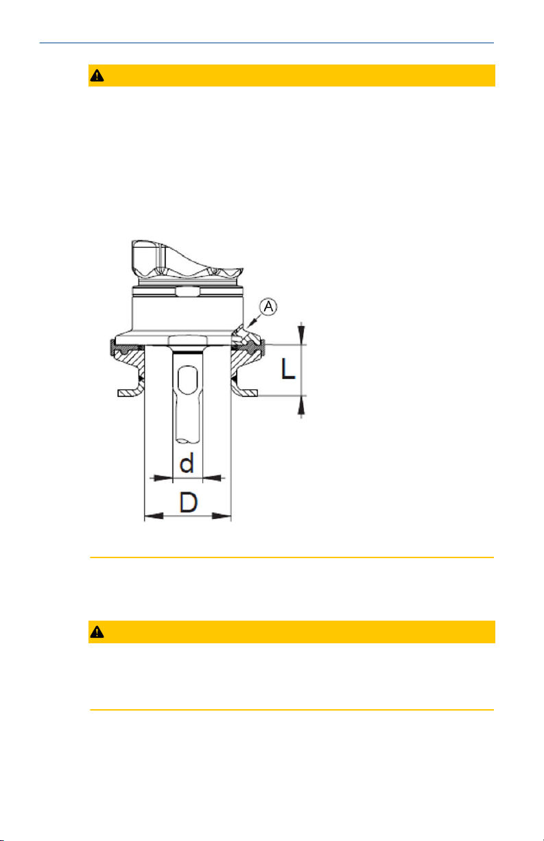
2.2.7 Installing with EHEDG standards
CAUTION
The unit is suited for CIP (cleaning in process) when installed correctly.
• Observe the application limits (temperature and material resistance)
according to the data sheet.
• Ensure the sensor is integrated into the system according to EHEDG:
— Use self-draining installation.
— Only use process adapters permitted according to EHEDG with
special seals required by the EHEDG position paper.
Quick Start Guide 21
Page 22
Quick Start Guide August 2020
CAUTION
The gasket of the system interface must not be in contact with the sealing
point of the sensor.
• In case of structures in a tank, the installation must be flush mount. If not
possible then direct water jet cleaning and cleaning of dead spaces must
be possible.
• Leakage ports must be clearly visible and must be installed facing
downwards for vertical pipes.
• To avoid dead space, adhere to the dimensions: L < (D - d).
A. Leakage port
2.3
Wire the transmitter
Wire the transmitter according the instructions and illustrations in this topic.
CAUTION
The level transmitter must be connected by a qualified electrician. Adhere to
national and international regulations for the installation of electrical
equipment.
Voltage supply according to EN 50178, SELV, PELV.
22 Quick Start Guide
Page 23

August 2020 Quick Start Guide
CAUTION
This devices requires additional surge protection for marine applications (if
approval is available for this device).
Procedure
1. Disconnect power to the level transmitter.
2. Connect the unit according to these diagrams (colors to DIN EN
60947-5-2):
OUT1: switching output / IO-Link
OUT2: analog output / switching output
BK: Black
BN: Brown
BU: Blue
WH: White
Note
After applying operating voltage to the level transmitter for the first
time, enter the probe length into the device parameters. After that,
the level transmitter is ready for operation. For more information,
see Enter probe length.
Example circuits
2 x positive switching
Quick Start Guide 23
2 x negative switching
Page 24

Quick Start Guide August 2020
1 x positive switching / 1 x analog 1 x negative switching / 1 x analog
24 Quick Start Guide
Page 25

August 2020 Quick Start Guide
3 Operation
The procedures in this section provide instructions for setting parameters
and settings on the level transmitter.
3.1 Display elements
The front of the level transmitter includes LED indicators, buttons, and an
alphanumeric display.
1 to 8: Indicator LEDs
LEDs 1 - 3 Selected unit of measurement.
LEDs 4 - 6 Not used.
LED 7 Active only if the switching output ou2 = I or InEG is selected;
LED 8 Switching status OUT1 (on when output 1 is switched).
9: Enter button
Open the user menu, edit and confirm the parameter values.
10 to 11: Arrow keys up [▲] and down [▼]
• Selection of the parameters
• Setting of the parameter values (continuously by holding pressed; incrementally
by pressing once).
12: Alphanumeric display, four digits
• Display of the current level.
• Display of the parameters and parameter values.
Quick Start Guide 25
then: switching status OUT2 (on when output 2 is switched).
Page 26

Quick Start Guide August 2020
3.2 Menu structure
The menu provides options for configuring parameters and viewing settings.
Note
Menu items highlighted in gray are active only after setting assigned
parameters.
• I: Main Menu (See Main menu options)
• II: Menu level EF (See Extended functions menu options (EF))
26 Quick Start Guide
Page 27

August 2020 Quick Start Guide
Note
Menu items highlighted in gray are active only after setting assigned
parameters.
• III: Level CFG (See Configuration menu options (CFG))
• IV: Level ENV (See Environment menu options (ENV))
• V: Level SIM (See Simulation menu options (SIM))
3.2.1 Main menu options
The main menu includes these options.
Option
tREF Carry out tank adjustment.
SP1/rP1 Set point 1 / reset point 1 at which OUT1 switches.
Quick Start Guide 27
Description
Visible only if LEnG ≥ 10.24 (260 mm).
Visible only after selecting hysteresis function (ou1 = H..)
Page 28
Quick Start Guide August 2020
Option Description
FH1/FL1 Upper / lower limit for the acceptable range within which
ASP2 Analog start point 2: measured value at which the analog start
AEP2 Analog end point 2: measured value at which the analog end
SP2/rP2 Set point 2 / reset point 2 at which OUT2 switches.
FH2/FL2 Upper / lower limit for the acceptable range within which
EF Extended functions / opening of menu level 2
OUT1 switches.
Visible only after selecting window function (ou1 = F..)
value is provided. The analog start value is set with parameter
ou2.
Visible only after selecting analog output (ou2 = I or InEG)
value is provided. The analog end value is set with parameter
ou2.
Visible only after selecting the analog output (ou2 = I or InEG)
Visible only after selecting the hysteresis function (ou2 = H..)
OUT2 switches.
Visible only after selecting the window function (ou2 = F..)
3.2.2 Extended functions menu options (EF)
The extended functions menu includes these options.
Option Description
rES Restore factory settings (all parameters including tank
CFG Open the configuration menu (CFG)
ENV Open the environment menu (ENV)
SIM Open the simulation menu (SIM)
adjustment)
3.2.3 Configuration menu options (CFG)
The configuration menu includes these options.
Option
ou1 Output configuration for OUT1: switching signal for level limit
ou2 Output configuration for OUT2:
28 Quick Start Guide
Description
value. Hysteresis or window function, normally closed or
normally open
• analog signal for current level, 4 - 20 mA or 20 - 4 mA
• Switching signal for level limit. Hysteresis or window
function, normally closed or normally open
Page 29

August 2020 Quick Start Guide
Option Description
dS1 Switch-on delay for OUT1
dr1 Switch-off delay for OUT1
(1)
dS2
(1)
dr2
uni Selection of the unit of measurement on the transmitter
P-n Output polarity of the switching outputs; positive or negative
FOU1 Response of OUT1 in case of a fault
FOU2 Response of OUT2 in case of a fault
SELd Selection of display options
dAP Damping of the measured signal (mean filter)
dFo Delay time for the outputs to pass into the state defined with
(1) Visible only after selecting hysteresis or window function (ou2 = H.. or F..).
Switch-on delay for OUT2
Switch-off delay for OUT2
display; mm or inch
switching
FOUx; only effective in case of a fault
3.2.4 Environment menu options (ENV)
The environment menu includes these options.
Option
LEnG Input of the probe length
MEdI Medium selection
Description
3.2.5 Simulation menu options (SIM)
The simulation menu includes these options.
Option
S.LvL Simulation of a level or an error state
S.Tim Simulation duration 1 - 60 minutes
S.On Simulation start/stop
Quick Start Guide 29
Description
Page 30

Quick Start Guide August 2020
3.3 Parameter settings
The level transmitter remains in operating mode while setting new
parameters. It continues to monitor using the existing parameters until new
parameters are set.
3.3.1 Read set parameters
Perform these steps to view the parameters set on the level transmitter.
Procedure
1. Press Enter to open the menu.
2. Press the up or down button to scroll through the set parameters.
3. Press Enter again to view the parameter value. The transmitter
displays the value for 30 seconds then returns to the process value
display.
3.3.2 Set parameters
Follow these steps to modify parameters values.
Procedure
1. Press Enter to open the menu.
2. Press the up or down buttons to navigate to a parameter.
3. Press Enter to select a parameter.
4. Press the up or down buttons for at least one second.
After one second the parameter value changes. Press and hold the
button to change the value continuously.
5. Press Enter.
The level transmitter saves the new value.
6. Repeat steps 2 - 5 to modify other parameters.
After 30 seconds of inactivity, the menu returns to the process view
display.
3.3.3 Change menu level
Perform these steps to move to the next menu level.
Procedure
1. Press Enter to get to the menu.
2. Press up or down until the menu displays EF.
3. Press Enter.
The display shows the next menu.
30 Quick Start Guide
Page 31

August 2020 Quick Start Guide
3.3.4 Lock or unlock the menu
Lock the menu to prevent unintentional changes to the parameters. By
default, the menu is unlocked. When the menu is locked, it briefly displays
Loc when you attempt to change a parameter value.
Prerequisites
The level transmitter must be in normal operating mode.
Procedure
1. Press and hold the up and down buttons simultaneously for 10
seconds.
The menu is locked and it displays Loc.
2. To unlock the menu, press and hold the up and down buttons for 10
seconds.
The menu is unlocked and it displays uLoc.
3.4 Setup the level transmitter
Procedures in this section provide instructions for configuring the settings
and parameters of the level transmitter.
3.4.1 Enter probe length
Enter the length of the probe into the parameters to ensure accurate level
measurements.
Procedure
1. Apply operating voltage.
The display shows the initial display.
2. Select LEnG from the menu.
If the parameter does not contain a value, the display shows nonE.
3. Press and hold up or down for at least one second. The display shows
the detected probe length.
4. If the detected probe length is incorrect, press up or down to change
the probe length to the correct value.
5. Press Enter.
The level transmitter proceeds to operating mode.
Notes
The level transmitter can automatically detect the length of the probe if:
• The tank is empty
• The level transmitter is mounted on a sufficiently large launching plate
Quick Start Guide 31
Page 32

Quick Start Guide August 2020
For instructions on manually determining the length of the probe, see
Record probe length.
3.4.2 Perform a tank adjustment
Tank adjustment reduces the effect of interference and ensures a higher
excess gain in difficult application conditions.
For more information on tank adjustments, see Tank adjustment.
Prerequisites
The tank adjustment menu option tREF appears only if the set probe length
is greater than or equal to 10.24 in (260 mm).
Procedure
1. Select tREF from the menu.
The display shows nonE or the value set by a previous tank
adjustment.
2. Press and hold up or down for at least one second.
The display shows the distance value. The default value is 0.39 in (10
mm).
3. If necessary, correct the value using the up and down buttons.
4. Press Enter.
The display shows donE.
5. Press Enter again.
The level transmitter reboots and returns to operating mode.
3.4.3 Configure the display
Modify how the level transmitter displays information.
Procedure
1. Change the unit of measurement.
a) Select uni from the menu.
b) Select mm for millimeters or inch for inches.
c) Press Enter.
2. Change the indicator.
a) Select SELd from the menu.
b) Set the type of indicator.
• L: The level indicated in millimeters or inches.
• %: The level indicated as a percentage. ASP2 corresponds
to 0% and AEP2 corresponds to 100%.
32 Quick Start Guide
Page 33

August 2020 Quick Start Guide
• OFF: The display is off by default. When a button is
pressed, the display turns on for 30 seconds.
Change display between length and percentage
While the level transmitter is in operating mode, it displays the set unit of
measurement. It can display the level measurement in a different unit of
measurement during operation mode.
For more information on setting the default unit, see Configure the display.
Procedure
1. Press up or down.
The display shows the level measurement in a different unit of
measurement.
2. Press up or down again to return it to the default unit of
measurement or wait for 30 seconds.
3.4.4 Set output signals
The procedures in this section provide instructions for modifying the output
signals.
Set output function for OUT1
Follow these steps to set the function for the output 1 (OUT1).
Procedure
1. Select ou1 from the menu.
2. Select a switching function.
• Hno: Hysteresis function / normally open
• Hnc: Hysteresis function / normally closed
• Fno: Window function / normally open
• Fnc: Window function / normally closed
Note
Use the Hnc switching function if the switching output is used as an
overflow prevention. The principle of normally closed operation
ensures that the level transmitter also detects wire breaks or cable
breaks.
Quick Start Guide 33
Page 34

Quick Start Guide August 2020
Set switching limits (hysteresis)
Use these steps to set the hysteresis limits for the switching output.
Procedure
1. Ensure that the function Hno or Hnc is set for ou1 or ou2.
2. Select SP1 or SP2 then set the value at which the output is set.
3. Select rP1 or rP2 then set the value at which the output is reset.
Note
rPx is always smaller than SPx. The level transmitter accepts only
values which are lower than the value for SPx. If SPx changes, rPx also
changes provided that the lower end of the setting range is not
reached.
Set switching limits (window)
Use these steps to set the limits for the window switching output.
Procedure
1. Ensure that the function Fno or Fnc is set for ou1 or ou2.
2. Select FH1 or FH2 then set the upper limit of the acceptable range.
3. Select FL1 or FL2 then set the lower limit of the acceptable range.
Note
FLx is always lower than FHx. The level transmitter accepts only
values which are lower than the value for FHx. If FHx changes, FLx
also changes provided that the lower end of the setting range is not
reached.
Set switch-on delay for switching outputs
Follow these steps to set the switch-on delay for switching outputs.
Procedure
1. Select dS1 or dS2 from the menu.
2. Set the value between 0.0 and 60 seconds.
Note
The switch-on delay reacts according to VDMA. According to VDMA,
the switch-on delay always effects SP and the switch-off delay always
effects rP irrespective of whether the level transmitter uses the
normally open or normally closed function.
34 Quick Start Guide
Page 35

August 2020 Quick Start Guide
Set switch off delay for switching outputs
Follow these steps to set the switch-off delay for switching outputs.
Procedure
1. Select dr1 or dr2 from the menu.
2. Set the value between 0.0 and 60 seconds.
Note
The switch-on delay reacts according to VDMA. According to VDMA,
the switch-on delay always effects SP and the switch-off delay always
effects rP irrespective of whether the level transmitter uses the
normally open or normally closed function.
Set output function for OUT2
Follow these steps to set the function for the output 2 (OUT2).
Procedure
1. Select ou2 from the menu.
2. Set the switching function:
• I: Current output 4-20 mA
• InEG: Current output 20-4 mA
• Hno: Hysteresis function/normally open
• Hnc: Hysteresis function/normally closed
• Fno: Window function/normally open
• Fnc: Window function/normally closed
Note
If using the output to prevent overflow, set ou2 = Hnc (NC function).
The principle of normally closed operation ensures that wire break or
cable break is also detected.
Scale analog signal
Follow these steps to modify the start and end points of the analog signal.
Procedure
1. Select ASP2 and set the analog start point.
2. Select AEP2 and set the analog end point.
Quick Start Guide 35
Page 36

Quick Start Guide August 2020
Note
Setting these parameters with IO-Link is possible only if parameter
ou2 = I or InEG.
For more information, see Analog signal.
Set output logic for switching outputs
Follow these steps to set the output logic for switching outputs.
Procedure
1. Select P-n from the menu.
2. Set PnP or nPn.
Set response of the outputs in case of fault
Follow these steps to modify how an output responds to faults.
Procedure
1. Select FOU1 to modify the response for output 1 or FOU2 to modify
the response for output 2 from the menu.
2. Set a value:
• On: Output switches ON in case of a fault.
The analog output switches to a value of greater than 21 mA in
case of a fault.
• OFF: Switching output switches OFF in case of a fault.
The analog output switches to a value of less than 3.6 mA in case
of a fault.
Fault examples
• Defective hardware
• Signal quality too low
Note
The level transmitter does not consider overflow to be a fault.
Set damping for measured signal
Follow these steps to set the damping time for a measured signal.
Procedure
1. Select dAP from the menu.
2. Set damping in seconds.
The setting range is between 0.0 to 60.0 seconds.
36 Quick Start Guide
Page 37

August 2020 Quick Start Guide
For more information, see Damping function.
Set delay time in case of a fault
Follow these steps to set the delay time after which the level transmitter
identifies a fault.
Procedure
1. Select dFo from the menu.
2. Set a value between 0.0 and 10.0 seconds.
Note
The parameter dFo is effective only in the case of a fault. Mind the
dynamics of your application. In case of fast level changes, change
the value step by step. For more information, see Fault states.
3.4.5 Reset all parameters to factory default settings
Follow these steps to reset all of the parameter values to the default factory
settings.
Procedure
1. Select rES from the menu.
2. Press Enter until rES is aligned right.
3. Press and hold up or down until the display shows ----.
4. Press Enter.
The level transmitter reboots and resets the parameter values to the
default factory settings.
Note
The level transmitter is operational only after entering basic settings.
For more information, see Menu structure.
3.4.6 Change basic settings
Set these parameters after making any changes to the probe length or
medium type.
Change the probe length
Modify the probe length parameter value after changing the length of the
probe.
Procedure
1. Select LEnG from the menu.
2. Enter the probe length (L).
Quick Start Guide 37
Page 38

Quick Start Guide August 2020
Note the set unit of measurement uni.
3. Press Enter.
Note
After changing the probe length, review or modify the values for the
switching limits. For more information, see Enter probe length.
Note
After changing the probe length, the unit deletes any existing tank
adjustment. If necessary, perform a tank adjustment again. For more
information, see Perform a tank adjustment.
Set to another medium
If the medium in the tank has changed, modify the parameters for the
medium to match the new medium.
Procedure
1. Select MEdI from the menu.
2. Set the medium type.
• HIGH: For water and water-based media.
Operating mode is optimized for suppression of deposits on the
probe.
• MId: For water-based media and media with a medium dielectric
constant value (oil-in-water emulsions).
Operating mode optimized for the detection of media with
increased foam build-up.
3. Press Enter.
Note
In case of doubt, perform an application test to ensure that the
setting is best suited for the medium.
3.4.7 Simulation
Simulation mode allows you to perform tests on the level transmitter while it
simulates levels and error scenarios.
Set simulation value
The simulation value determines what error scenario the simulation shows.
Procedure
1. Select S.LvL from the menu.
2. Set the simulation value:
38 Quick Start Guide
Page 39

August 2020 Quick Start Guide
• Numerical value: level in millimeters or inches (depending on the
basic setting)
• FULL: full state
• SEnS: weak measured signal
• Err: electronic fault found
• EPTY: empty state
3. Press Enter.
Set simulation duration
The simulation duration parameter sets the length in time of the simulation.
Procedure
1. Select S.Tim from the menu.
2. Set time span for simulation.
Setting range: 1, 2, 3, 4, 5, 10, 15, 20, 30, 45, 60 minutes
Factory setting: three minutes
3. Press Enter.
Switch simulation on or off
Switching the simulation on starts the simulation and switching it off cancels
the simulation.
Procedure
1. Select S.On from the menu.
2. Select On or OFF.
3. Press Enter.
Note
The simulation is active until Enter is pressed again or the time set via
S.Tim elapses. During the simulation, the level transmitter displays
SIM every three seconds. After the simulation, the level transmitter
goes again to the parameter S.On and internally the level transmitter
goes again to the operating mode (and the process value
transmission).
After another 30 seconds the display goes again to the process value
display.
Quick Start Guide 39
Page 40

Quick Start Guide August 2020
Note
If using IO-Link to start and configure a simulation, it can be canceled
only using IO-Link. The level transmitter displays C.Loc if the
simulation is attempted to be canceled with the function buttons.
3.5 Using the transmitter
The procedures in this section provide instructions for operating the level
transmitter.
3.5.1 Operation with a single probe
Using the level transmitter with a single probe is suited for the detection of
aqueous media, especially heavily soiled aqueous media.
Note
The level transmitter is intended only for operation with a single probe. A
coaxial probe is not available for this unit.
To correctly transfer the microwave pulse to the tank with optimum
transmission power, the level transmitter needs a sufficiently large metal
launching surface or launching plate.
For installation in closed metal tanks or metal bypass pipes, the tank lid or
upper pipe section serves as a launching surface. Use a sufficiently large
fixing plate, metal plate or something similar when installing in open metal
tanks, plastic tanks, or metal tanks with plastic lids. For more information,
see Installing in an open tank or Installing in a plastic tank.
3.5.2 Operation with a bypass or still pipe
Use a bypass or a still pipe in applications like heavy foam build-up.
For more information about heavy foam build-up and turbulence, see Heavy
foam build-up and turbulence.
For more information about the minimum internal pipe diameter, see
Installation in pipes.
For general installation instructions, see Installation.
3.5.3 Function check
After turning on the level transmitter, it is in operating mode. It measures
and evaluates level and generates output signals according to the set
parameters.
Check that the level transmitter is operating correctly before using it in a
production environment.
40 Quick Start Guide
Page 41

August 2020 Quick Start Guide
3.5.4 Operation indication
These indicators show how the level transmitter is operating.
Indicator Definition
---- continuous Initialization phase after power on
Initially the level transmitter is not operational. Configure
basic settings to enable the level transmitter (see Change
basic settings).
---- Level below the active zone
Numerical value +
LED 1
Numerical value +
LED 2
Numerical value +
LED 3
LED 7 / LED 8 Switching status OUT2/OUT1
FULL + numerical
value alternately
SIM + XXX Simulation active. XXX = state to be simulated (See
S.On Simulation stopped (See Simulation)
Loc The level transmitter is locked using the function buttons.
uLoc The level transmitter is unlocked or the parameter setting is
C.Loc The level transmitter is temporarily locked. Parameter setting
S.Loc The level transmitter permanently locked via IO-Link.
Current level in millimeters
Current level in inches
Current level in percent of the scaled measuring range
Level has reached or exceeded the maximum measuring range
(= overflow warning).
Simulation)
Setting parameter values is not possible without unlocking the
level transmitter. To unlock the level transmitter, press and
hold up and down for 10 seconds.
possible again.
via IO-Link is active.
Unlocking is possible only via IO-Link.
Quick Start Guide 41
Page 42

Quick Start Guide August 2020
3.6 Setting parameters with IO-Link
During setup, send valid basic settings to the device even if the default
settings correspond to the connected device. Enter the basic settings
correctly according to the attached probe and the medium to be detected.
3.6.1 Set parameters using IO-Link
Use IO-Link software to set parameter settings on the level transmitter using
a computer.
Procedure
1. Enter probe length (LEnG). Example: LEnG = 1000 mm.
2. Scale analog output (ASP2 and AEP2; AEP2 must at least be 20 %
greater than ASP2). Example: AEP2 = 970 mm.
3. Alternatively: Set parameter ou2 to H.. or F...
4. Select the medium (MEdI). Example: MEdI = MId.
• HIGH = For water and water-based media. Operating mode is
optimized for suppression of deposits on the probe.
• MId = For water-based media and media with a mean dielectric
constant value. Operating mode is optimized for media with
increased foam build-up.
5. Transfer the transmitter data to the unit.
6. Carry out tank adjustment depending on the installation (tREF or
button "TEACH_TANK_REF".
To change the adjustment distance (RefDist), send this individual
parameter to the transmitter first. Then, perform a tank adjustment.
Select the adjustment distance according to, for example, the height
of connection pieces or the position of structures in the tank. Within
the adjustment distance, starting from the process connection,
interfering reflections are compensated. Example: RefDist = 50 mm.
7. Modify any other parameter values.
Note
Only if data storage is required in an IO-Link application:
IO-Link does not save tank adjustment information. After the level
transmitter fails, perform another tank adjustment. The level
transmitter reverts to the cyclical process data transmission after
performing a tank adjustment successfully.
After a factory reset, the device reboots and the factory settings are
restored.
42 Quick Start Guide
Page 43

August 2020 Quick Start Guide
3.6.2 Unit locking and data storage
The IO-Link master saves all parameters of the connected transmitter
(except tank adjustment) if configured in the master (data storage). When a
transmitter is replaced by a transmitter of the same type, the parameters of
the old transmitter are automatically written to the new transmitter if
configured in the master and if the transmitter allows this.
For safety reasons, the level transmitter can refuse the parameter download.
Factory default setting: Open
Data storage
• Open: the transmitter allows parameter download from the master
• Locked: the transmitter refuses parameter download from the master
Quick Start Guide 43
Page 44

Quick Start Guide August 2020
4 Troubleshooting and maintenance
The topics in this section provide information on identifying and resolving
issues and maintaining the level transmitter.
4.1 Error indicators
This table describes error scenarios for the level transmitter and possible
solutions.
Indicator Possible cause Recommended fix
Err Fault in the electronics. Replace the unit.
nPrb Probe detached from the unit;
possibly incorrect setting of the
probe length.
SEnS Measurement disturbed by heavy
foam build-up or turbulence.
Check whether the probe is still
attached to the unit. Check the
parameter LEnG.
• Install the unit in a still pipe or
bypass (Installation)
• Set or increment dFo (Set
delay time in case of a fault)
Measurement disturbed by
separation layers (e.g. oil layer on
water).
Probe or process connection
soiled.
Installation conditions not
adhered to.
Probe length or sensitivity
(setting to the medium)
incorrect.
SCx + LED 7
SCx + LED 8
SC + LED 7
+ LED 8
PArA Faulty data set Restore factory default settings
Flashing: short circuit in switching
output OUT1 or OUT2.
Flashing: short circuit in both
switching outputs
Remove the oil layer by suction,
stir the medium, verify the
composition.
Clean the probe and the process
connection.
• Observe the notes in
Installation.
• Repeat or perform a tank
adjustment. (Tank
adjustment)
Correct settings then perform a
tank adjustment (Tank
adjustment).
Remove the short circuit.
Remove the short circuit.
(See Reset all parameters to
factory default settings)
44 Quick Start Guide
Page 45

August 2020 Quick Start Guide
4.2 Output response in different operating states
These tables provide information on the response of outputs for different
operating states.
Operating state OUT1 OUT2
Initialization OFF OFF
Normal operation According to the level and
ou1 setting
Fault OFF with FOU1 = OFF;
ON with FOU1 = On
(1) If the analog function ou2 = I has been selected. If the switching function has
been selected: see column OUT1.
Additions to the analog output
Full signal With ou2 = I: 20 - 20.5 mA
With ou2 = InEG: 4 - 3.8 mA
Empty signal With ou2 = I: 4 - 3.8 mA
With ou2 = InEG: 20 - 20.5 mA
(1)
According to the level 4 20 mA
< 3.6 mA with FOU2 = OFF
> 21 mA with FOU2 = On
4.3 Maintenance
This section includes notes on maintaining the level transmitter.
• Keep the process connection free of deposits and foreign bodies.
• In case of heavy soiling: clean the process connection and probe. For
cleaning purposes, the level transmitter can be removed from the
adapter and the probe can be screwed off the unit.
CAUTION
Before installing or removing the unit:
— Ensure no pressure is applied to the system and there is no medium
in the tank that could leak.
— Note the potential dangers related to extreme machine and medium
temperatures.
• Use only tools suitable for plastic surfaces for wetted surfaces.
• Ensure gasketed connections (probe or process connection adapter) are
not soiled or damaged. Check sealing rings for damage.
Quick Start Guide 45
Page 46

Quick Start Guide August 2020
• Replace any damaged parts.
• After changing the medium, it may be necessary to change the settings
of the level transmitter. (See Set to another medium)
• IO-Link does not save tank adjustment information. After replacing the
transmitter, perform another tank adjustment. (See Perform a tank
adjustment)
• It is not possible to repair the level transmitter.
• After use, dispose of the unit in an environmentally friendly way in
accordance with the applicable national regulations.
• In case of returns, ensure that the unit is free from soiling, especially
dangerous and toxic substances.
4.3.1 Cleaning and maintenance in 3-A® applications
Follow these steps when cleaning the level transmitter in a 3-A compliant
environment. Regularly perform clean out of place (COP) cleaning on the
level transmitter to conform to 3-A standards.
Prerequisites
Before installing the level transmitter:
• Ensure that no pressure is applied to the system and that there is no
media in the tank that could leak.
• Note the potential dangers related to extreme machine and medium
temperatures.
Procedure
1. Remove the probe from the unit.
2. Remove O-ring from the transmitter.
3. Remove O-ring from the groove and clean it.
4. Check O-ring and groove.
5. Reassemble the level transmitter.
4.3.2 Transport
When transporting the level transmitter, follow these guidelines to avoid
damage.
• Use only appropriate packaging.
• If installed in a tank or pipe, protect the tank or pipe and the level
transmitter against shock and vibration. Protect the probe against
deflections and vibrations. If necessary, fix at several points to prevent
movement of unstable areas.
46 Quick Start Guide
Page 47

August 2020 Quick Start Guide
5 Setting ranges
These tables show the setting ranges for the level transmitter parameters.
LEnG inch mm
Setting range 6.0 - 78.8 150 - 2000
Step increment 0.2 5
The setting ranges for the switching limits (SPx, rPx, FHx, FLx) depend on the
probe length (L). In general the following applies:
Parameters inch mm
min max min max
SPx/FHx 0.6 L - 1.2 15 L - 30
rPx/FLx 0.4 L - 1.4 10 L - 35
Step
increment
rPx/FLx is always smaller than SPx / FHx. If SPx / FHx is shifted, rPx / FLx also
shifts provided that the lower end of the setting range is not reached. Always
set SPx / FHx first, then rPx/FLx.
The setting ranges for analog start point ASP2 and analog end point AEP2
depend on the probe length (L). In general the following applies:
0.05 1
Parameters
ASP2 0 N/A 0 N/A
AEP2 N/A L - 1.2 N/A L - 30
Step
increment
inch mm
min max min max
0.05 1
Minimum distance between ASP2 and AEP2 is 20 percent of the active zone.
Quick Start Guide 47
Page 48

Quick Start Guide August 2020
6 Product certifications
6.1 European directive information
The most recent revision of the EC Declaration of Conformity can be found
at Emerson.com/Rosemount.
6.2 Ordinary location information
As standard, this product has been examined and tested to determine that
the design meets the basic electrical, mechanical, and fire protection
requirements by a nationally recognized test laboratory (NRTL) as accredited
by the Federal Occupational Safety and Health Administration (OSHA).
6.3 3-A® certification
This product is authorized to display the 3-A symbol. Ensure gaskets and
process connection accessories selected for installation meet both the
application and 3-A requirements. A certificate of compliance is available at
Emerson.com/Rosemount.
6.4 Other industry certifications
All Rosemount 326L transmitter surfaces and materials which come into
contact with process medium comply with the following regulations:
48 Quick Start Guide
Page 49

August 2020 Quick Start Guide
7 Factory settings
Use this worksheet to record modified parameter settings.
Parameter Factory default setting User-defined setting
tREF nonE
SP1 50% VMR
rP1 0.2 in (5 mm) below SP1
ASP2 0 % VMR
AEP2 100 % VMR
dS1 0.0
dr1 0.0
ou1 Hno
ou2 I
uni inch
P-n PnP
FOU1 OFF
FOU2 OFF
SELd L
dAP 0.0
dFo 3.0
LEnG nonE
MEdl MID
S.LVL 50 % LEnG
S.Tim 3
S.On OFF
(1)
(1)
(1)
(1) VMR = final value of the measuring range = LEnG value minus 1.18 in (30 mm).
When the LEnG value is entered, the unit calculates the basic setting.
Quick Start Guide 49
Page 50

Quick Start Guide August 2020
50 Quick Start Guide
Page 51

August 2020 Quick Start Guide
Quick Start Guide 51
Page 52

*00825-0100-4326*
00825-0100-4326, Rev. 02
Quick Start Guide
August 2020
Emerson Automation Solutions
6021 Innovation Blvd
Shakopee, MN 55379, USA
+1 800 999 9307 or +1 952 906 8888
+1 952 949 7001
RFQ.RMD-RCC@Emerson.com
Linkedin.com/company/Emerson-
Automation-Solutions
Twitter.com/Rosemount_News
Facebook.com/Rosemount
Youtube.com/user/
RosemountMeasurement
North America Regional Office
Emerson Automation Solutions
8200 Market Blvd.
Chanhassen, MN 55317, USA
+1 800 999 9307 or +1 952 906 8888
+1 952 949 7001
RMT-NA.RCCRFQ@Emerson.com
©
2020 Emerson. All rights reserved.
Emerson Terms and Conditions of Sale are
available upon request. The Emerson logo is a
trademark and service mark of Emerson Electric
Co. Rosemount is a mark of one of the Emerson
family of companies. All other marks are the
property of their respective owners.
 Loading...