

Page 1

Artisan Technology Group is your source for quality
new and certied-used/pre-owned equipment
• FAST SHIPPING AND
DELIVERY
• TENS OF THOUSANDS OF
IN-STOCK ITEMS
• EQUIPMENT DEMOS
• HUNDREDS OF
MANUFACTURERS
SUPPORTED
• LEASING/MONTHLY
RENTALS
• ITAR CERTIFIED
SECURE ASSET SOLUTIONS
SERVICE CENTER REPAIRS
Experienced engineers and technicians on staff
at our full-service, in-house repair center
Instra
Remotely inspect equipment before purchasing with
our interactive website at www.instraview.com
Contact us: (888) 88-SOURCE | sales@artisantg.com | www.artisantg.com
SM
REMOTE INSPECTION
View
WE BUY USED EQUIPMENT
Sell your excess, underutilized, and idle used equipment
We also offer credit for buy-backs and trade-ins
www.artisantg.com/WeBuyEquipment
LOOKING FOR MORE INFORMATION?
Visit us on the web at www.artisantg.com for more
information on price quotations, drivers, technical
specications, manuals, and documentation
Page 2

High Purity pH Sensor
Instruction Manual
PN 51-320HP/rev.J
May 2006
Model 320HP
Page 3

CAUTION
SENSOR/PROCESS
APPLICA
TION COMPATIBILITY
The wetted sensor materials may not
be compatible with process composition and operating conditions.
Application compatibility is entirely
the responsibility of the user.
DANGER — HAZARDOUS AREA
INSTALLATION
Installations near flammable liquids or in hazardous area locations must be carefully evaluated by qualified on site safety personnel. This
sensor is not Intrinsically Safe or Explosion
Proof.
To secure and maintain an intrinsically safe
installation, the certified safety barrier, transmitter, and sensor combination must be used.
The installation system must comply with the
governing approval agency (FM, CSA or
BASEEFA/ CENELEC) hazardous area classification requirements. Consult your analyzer/ transmitter instruction manual for details.
Proper installation, operation and servicing of
this sensor in a Hazardous Area Installation is
entirely the responsibility of the user.
ESSENTIAL INSTRUCTIONS
READ THIS PAGE BEFORE PROCEEDING!
Rosemount Analytical designs, manufactures, and tests its products to meet many
national and international standards. Because these instruments are sophisticated
technical products, you must properly install, use, and maintain them to ensure they
continue to operate within their normal specifications. The following instructions
must be adhered to and integrated into your safety program when installing, using,
and maintaining Rosemount Analytical products. Failure to follow the proper instructions may cause any one of the following situations to occur: Loss of life; personal
injury; property damage; damage to this instrument; and warranty invalidation.
• Read all instructions prior to installing, operating, and servicing the product. If this
Instruction Manual is not the correct manual, telephone 1-800-654-7768 and the
requested manual will be provided. Save this Instruction Manual for future reference.
• If you do not understand any of the instructions, contact your Rosemount representative for clarification.
• Follow all warnings, cautions, and instructions marked on and supplied with the
product.
• Inform and educate your personnel in the proper installation, operation, and
maintenance of the product.
• Install your equipment as specified in the Installation Instructions of the appropriate Instruction Manual and per applicable local and national codes. Connect
all products to the proper electrical and pressure sources.
• To ensure proper performance, use qualified personnel to install, operate,
update, program, and maintain the product.
• When replacement parts are required, ensure that qualified people use replacement parts specified by Rosemount. Unauthorized parts and procedures can
affect the product’s performance and place the safe operation of your process at
risk. Look alike substitutions may result in fire, electrical hazards, or improper
operation.
• Ensure that all equipment doors are closed and protective covers are in place,
except when maintenance is being performed by qualified persons, to prevent
electrical shock and personal injury.
Emerson Process Management
Liquid Division
2400 Barranca Parkway
Irvine, CA 92606 USA
Tel: (949) 757-8500
Fax: (949) 474-7250
http://www.raihome.com
© Rosemount Analytical Inc. 2006
About This Document
This manual contains instructions for installation and operation of the Model 320HP High Purity pH
Sensor. The following list provides notes concerning all revisions of this document.
Rev
. Level Date Notes
0 1/01 This is the initial release of the product manual. The manual has been refor-
matted to reflect the Emerson documentation style and updated to reflect any
changes in the product offering.
A 7/02 Updated multiple drawings throughout.
B 8/02 Added drawing 40105544.
C 11/02 Revised figure 2-5 on page 6.
D 1/03 Updated drawings on pages 9 & 10.
E 11/03 Update figure 2-5.
F 5/04 Add wiring drawings to models Xmt & 5081.
G 12/04 Updated Figure 2-9 on page 8.
H 1/05 Revised Figures 2-5 and 2-12; delete Figures 2-3 and 2-6
I 5/05 Revised drawings on pages 8 & 9.
J 5/06 Revised Table 5-1 on page 19.
Page 4

MODEL 320HP TABLE OF CONTENTS
MODEL 320HP
HIGH PURITY PH SENSOR
TABLE OF CONTENTS
Section Description Page
1.0 DESCRIPTION AND SPECIFICATIONS............................................................................1
1.1 Features and Applications...................................................................................................1
1.2 Operation ............................................................................................................................1
1.3 Sensor Specifications..........................................................................................................1
1.4 Ordering Information ...........................................................................................................2
2.0 MECHANICAL INSTALLATION .........................................................................................3
2.1 General ...............................................................................................................................3
2.2 Unpacking ...........................................................................................................................3
2.3 Preparation for Installation .................................................................................................3
2.4 Installation Inspection ........................................................................................................5
3.0 OPERATION .....................................................................................................................11
3.1 General .............................................................................................................................11
3.2 Calibration .........................................................................................................................11
4.0 MAINTENANCE AND TROUBLESHOOTING ................................................................12
4.1 General .............................................................................................................................12
4.2 Preventative Maintenance ................................................................................................12
4.3 Troubleshooting ...............................................................................................................13
4.4 Maintenance .....................................................................................................................14
5.0 PARTS LIST ....................................................................................................................19
5.1 General .............................................................................................................................19
6.0 RETURN OF MATERIALS ...............................................................................................21
6.1 General .............................................................................................................................21
6.2 Warranty Repair................................................................................................................21
6.3 Non Warranty Repair ........................................................................................................21
i
Page 5

MODEL 320HP TABLE OF CONTENTS
MODEL 320HP
HIGH PURITY PH SENSOR
TABLE OF CONTENTS (CONT.)
LIST OF FIGURES
Figure No. Title Page
2-1 Liquid Junction Installation....................................................................................... 3
2-2 Model 320HP Dimensional Drawing ........................................................................ 4
2-3 Model 320HP-50/51/54 Wiring to Models 1054A/B, 2054, 2081, 1181, 1003, 1050 5
2-4 Model 320HP-55 Wiring to Models 54/54e, 81, 3081, 4081, and 5081 ................... 6
2-5 Model 320HP-55 Wiring to Model Xmt-P-HT-10...................................................... 7
2-6 Model 320HP-58 Wiring to Model Xmt-P-HT-10...................................................... 7
2-7 Model 320HP-58 Wiring to Models 54e, 81, 3081, 4081, and 5081 ........................ 8
2-8 Model 320HP-55 Wiring to Model 1055-22-32 ........................................................ 9
2-9 Model 320HP-58 Wiring to Model 1055-22-32 ........................................................ 9
2-10 Model 320HP Wiring to Model 1055-01-10-22 ........................................................ 10
3-1 Buffer Cup Fixture ................................................................................................... 11
4-1 Preamplifier Check ................................................................................................. 14
4-2 Reference Electrode Check..................................................................................... 16
4-3 Glass Electrode Test Method .................................................................................. 17
4-4 Temperature Compensator Check .......................................................................... 17
5-1 Model 320 HP (Front View and Side View) Component Locator............................. 20
LIST OF TABLES
Table No. Title Page
4-1 Troubleshooting without Diagnostics ....................................................................... 13
4-2 Troubleshooting with Diagnostics ............................................................................ 15
4-3 Temperature vs. Resistance ................................................................................... 18
4-4 R
o
& R1 Value for Temperture Compensation Elements ......................................... 18
5-1 Parts List.................................................................................................................. 19
ii
Page 6

1
MODEL 320HP SECTION 1.0
DESCRIPTION AND SPECIFICATIONS
SECTION 1.0
GENERAL DESCRIPTION AND SPECIFICATIONS
• CORROSION-RESISTANT, WEATHERPROOF CONSTRUCTION permits installation in
almost any environment.
• UNIQUE SENSOR DESIGN provides accurate, stable pH measurement in high purity water.
• ELECTRONICALLY SHIELDED GLASS ELECTRODE protects against electrostatic
noise pickup.
• INCLUDES ROTAMETER AND NEEDLE VALVE to assure an accurate, stable measurement.
• CONVENIENT SHELF to hold electrodes for buffer calibration.
1.1 FEATURES AND APPLICATIONS
The Rosemount Analytical Model 320HP High-Purity
pH Sensor is uniquely designed for pH measurement
in aqueous solutions of very low dissolved solids content (below 50 microsiemenss). The sensor assembly
consists of a stainless steel flow cell, glass electrode,
a double junction Kynar1reference cell with specially
designed liquid junction, temperature compensator,
rotameter, needle valve and a weatherproof junction
box containing an optional preamplifier. All components are mounted on an ABS plate which may be
attached to a wall or clamped (optional) to a two-inch
pipe.
The electrical resistance of high-purity water is very
high, typically one megohm or more. Such liquids can
generate a considerable static charge when flowing
over an essentially nonconductive (plastic) surface.
An adequate discharge path to a good earth ground
must be provided for this static charge; otherwise, it
can be easily picked up by the high impedance pH
electrode causing excessive noise in the measuring
signal. The well-grounded metallic flow cell in the
Model 320HP High-Purity pH Sensor surrounds the
pH electrode and provides an effective discharge path
to ground for any static charges. It also serves as an
electronic shield against outside interference from AC
power lines, arcing electrical equipment, and other
similar sources of noise.
1.2 OPERATION
Accurate pH measurement in high-purity water
depends on a stable reference junction potential, and
this requirement is met by the unique design of the reference junction in the high-purity sensor. The construction of the junction serves to minimize any
changes in junction potential which are caused by variations in flow rate of the high-purity water over the
junction surface. The flowmeter and needle valve aid in
maintaining the low, constant sample flow required for
a stable reference junction potential.
1.3 SENSOR SPECIFICATIONS
Style: Flow-through
Wetted Materials: Kynar, Buna-N, glass, stainless
steel, ABS, Teflon2Viton2, Polypropylene
Range: 0 to 14 pH
Sample Temperature: 4°C to 71°C (39°F to 160°F)
Sample Pressure Required: 5 to 10 psig
Sample Flow Rate: Constant in the region of 0.8 to
2.4 gal/hour
Process Connections: 1/4-inch tube
Reference Electrode: Sealed, double junction
Measuring Electrode: Glass, GPHT (0-13pH)
1
Kynar is a registered trademark of Elf Atochem North America, Inc.
2
Teflon and Viton are registered trademarks of E.I. duPont de Nemours & Comp.
Page 7

1.4 ORDERING INFORMATION
Model 320HP Flow Through High-Purity pH Sensor is designed for use when conductivity is below 50 μS.
The sensor includes a 316 stainless steel flow cell, a double junction Kynar reference cell with specially
designed liquid junction, pH glass electrode, temperature compensator, and a weatherproof junction box containing an optional preamplifier. A rotameter and a needle valve are included on the input side of the flow cell for
monitoring and control of the sample flow. All components are mounted on an ABS plate which is suitable for
wall or pipe mounting.
2
MODEL 320HP SECTION 1.0
DESCRIPTION AND SPECIFICATIONS
MODEL
320HP FLOW THROUGH HIGH-PURITY pH SENSOR
Code Measuring Electrode (required selection)
10 General Purpose pH
Code Preamplifier (
required selection
)
50 Preamp and 3K T.C. for use with Model 1181pH (requires cable PN 9200000)
54 Preamp and Pt100 T.C. for use with Models 1054A/B, 2054, & 2081 (requires cable PN 9200000)
55 No Preamp and Pt100 T.C. for use with Models 54/54e, 1055, 81, 3081, 4081, 5081, Xmt, and
SCL-P (requires cable PN 661-646983)
56 Preamp and Pt100 T.C. for use with SCL-P (requires cable PN 661-892884)
57 Preamp and Pt100 T.C. for use with Model 2700 (requires cable PN 661-898695)
58 Preamp and Pt100 T.C. for use with Models 54/54e, 81, 3081, 4081, 5081, and Xmt (requires
cable PN 9200273)
NOTE: Interconnecting cable is required. Specify length.
PART # DESCRIPTION
2001492 Tag, Stainless Steel, specify marking (Formerly Code -40)
22698-02 Preamplifier, Plug-in, 1181/1050 compatible
22698-03 Preamplifier, Plug-in, 1054/A, 2054, 2081 compatible
23722-00 Pipe/Wall Mounting Bracket (Formerly Code -30)
661-646983 Cable, 4 conductor, 1 coax (for option -55), per ft
661-892884 Cable, 7 conductor (for option -56), per ft
661-898695 Cable, 5 conductor (for option -57), per ft
9200000 Cable, 4 conductor, 20AWG, 1 pair shielded (for option -50 and -54), per ft
9200273 Cable, 11 conductor, shielded, unprepped (for option -58), per ft
320HP 10 50 EXAMPLE
ACCESSORIES
Page 8
MODEL 320HP SECTION 2.0
MECHANICAL INSTALLATION
SECTION 2.0
MECHANICAL INSTALLATION
2.1 GENERAL
The sensor requires some customer assembly, therefore care should be taken that the instructions are followed carefully to ensure all parts are properly
installed.
2.2 UNPACKING
Inspect the shipping container. If evidence of damage
is noted, contact the carrier. If no damage is evident,
open the container and inspect the sensor for damage.
Again, if damage is apparent, notify the carrier. Save
the shipping container and all packing material. This
will help prevent damage during transit should the sensor ever require factory servicing.
2.3 PREPARATION FOR INSTALLATION
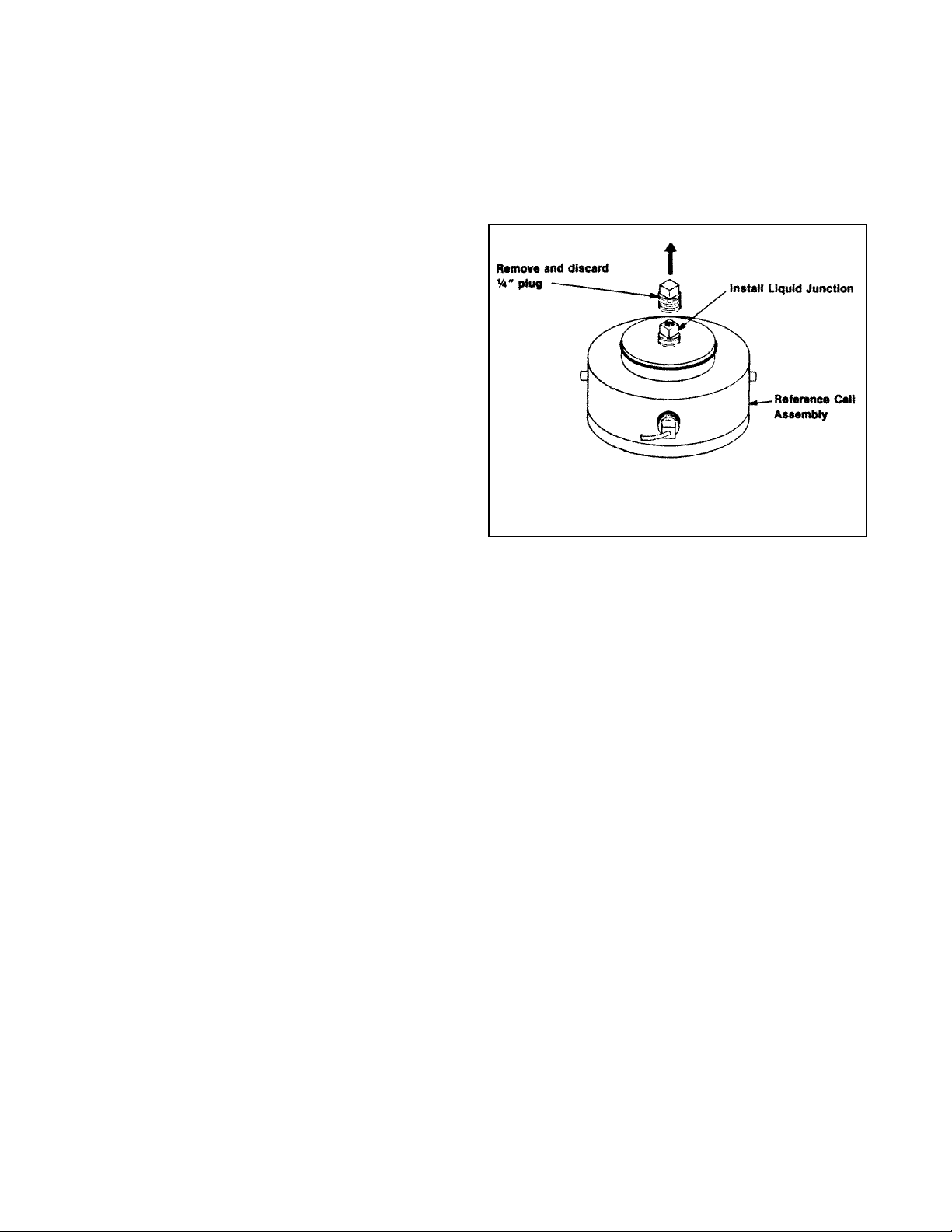
Prepare the sensor for installation as follows:
1. Remove the reference cell by turning it about ten
degrees clockwise and pulling it straight out. Hold
the cell in the position shown in Figure 2-1 and
remove the solid plug from the reference cell body.
Gently break away any salt crust which may have
formed around or inside the opening. Top off the reference cell with distilled water, tapping the cell gently to dislodge any air bubbles. Install the liquid junction supplied (PN 2001317). It is not necessary to
use thread sealants. Teflon tape may be used if a
loose fit is observed. The use of sticky “pipe dope”
compounds should be strictly avoided. Use care not
to get any greasy materials on the surface of the liquid junction. As the plug is installed, beads of water
should appear on the surface of the liquid junction
as water is forced through the porous material. If
water beads are not present on the junction surface
the liquid junction should be replaced (PN 2001317).
2. Lubricate the o-ring on the reference cell using the oring lubricant supplied (PN 2001928). Place the reference cell back on the flow cell. Rotate it counterclockwise until the ears seat in the retainer brackets.
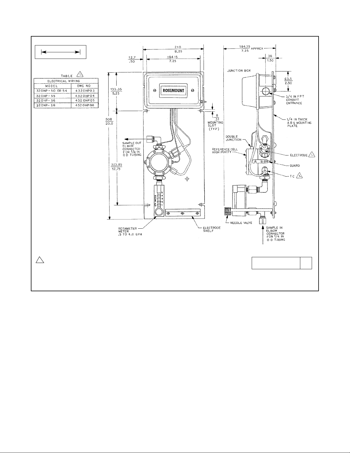
3. Install sensor panel so the process flow will enter at the
bottom of the cell and exit from the top (Figure 2-2).
Make sure that the panel is securely attached to the
mounting surface.
2.3.1 Plumbing. Plumb the sensor from sample line to
discharge. Be careful not to over tighten these connections. Plastic parts can be cracked by excessive
force. The distance from the sample line should be as
short as possible to minimize lag time in control applications.
2.3.2 Electrical Installation. Figures 2-3 through 2-10
provide the guidelines for wiring the 320HP sensor to
the ABS junction box with a built-in preamplifier to various analyzer/transmitter instruments.
Refer to Figure 2-2 and proceed as follows:
1. Make sure the conduit fittings are properly attached
to the enclosure junction box.
2. Install the pH electrode into the sensor’s flow cell as
shown in Figure 2-2.
3. Plug the preamplifier into the junction box.
4. Connect the pH electrode to the preamplifier.
5. Connect the temperature compensator.
6. Ensure that guard wire is connected to the stainless
steel flow cell.
7. Make the required connections to the instrument.
Use care to dress the wires so they are not exposed
and susceptible to shorting or grounding.
(Recommended cables are listed on page 2)
NOTE
Do not run signal cable next to A.C. Iines.
8. Attach the junction box cover, making sure the gasket seal keeps moisture out of the box.
FIGURE 2-1. Liquid Junction Installation
3
Page 9
4
MODEL 320HP SECTION 2.0
MECHANICAL INSTALLATION
FIGURE 2-2. Model 320HP Dimensional Drawing
DWG. NO. REV.
4320HP01 C
MILLIMETER
INCH
1
Shipped loose customer install and wire. For electrical
wiring see Table above.
Page 10

5
MODEL 320HP SECTION 2.0
MECHANICAL INSTALLATION
2.4 INSTALLATION INSPECTION
Prior to operating the sensor and attempting to standardize the instrument, inspect the sensor installation
as follows:
1. Verify that the sensor is securely attached to the
wall, pipe, or other mounting surface.
2. Check all plumbing connections for leaks. If any are
evident, repair them.
3. Check all electrical connections for security. Make
sure all wires are properly dressed so they do not
short or ground. Make sure the instrument is wired
as illustrated in Figure 2-3 through 2-10.
4. If all of the above have been satisfied, proceed to
the next section.
FIGURE 2-3. Model 320HP-50/51/54 Wiring to MODELS 1054/A/B, 2054, 2081, 1181, 1003, 1050
DWG. NO. REV.
40320HP03 A
Page 11

6
MODEL 320HP SECTION 2.0
MECHANICAL INSTALLATION
FIGURE 2-4. Model 320HP-55 Wiring to Models 54/54e, 81, 3081, 4081, and 5081
DWG. NO. REV.
4320HP04 C
Page 12

MODEL 320HP SECTION 2.0
MECHANICAL INSTALLATION
7
FIGURE 2-6. Model 320HP-58 Wiring to Xmt-P-HT-10
FIGURE 2-5. Model 320HP-55 Wiring to Xmt-P-HT-10
Page 13

8
MODEL 320HP SECTION 2.0
MECHANICAL INSTALLATION
FIGURE 2-7. Model 320HP-58 Wiring to Models 54e, 81, 3081, 4081, and 5081
DWG. NO. REV.
4320HP09 A
Page 14

MODEL 320HP SECTION 2.0
MECHANICAL INSTALLATION
FIGURE 2-9. Model 320HP-58 Wiring to Model 1055-22-32
FIGURE 2-8. Model 320HP-55 Wiring to Model 1055-22-32
9
Page 15

MODEL 320HP SECTION 2.0
MECHANICAL INSTALLATION
FIGURE 2-10. Model 320HP Wiring to Model 1055 Pipe/Wall Mount
10
MODEL 320HP-58
MODEL 320HP-55
Page 16

11
MODEL 320HP SECTION 3.0
OPERATION
SECTION 3.0
OPERATION
3.1 GENERAL
This section contains adjustment, standardization, and setup instructions to put the sensor in operation. The sensor is
completely automatic and may require only an occasional
electrode cleaning and reference electrolyte replenishment.
See Maintenance, Section 4.0 for instructions.
3.2 START-UP CALIBRATION PROCEDURE
3.2.1 Buffer Calibration Method
1. Ensure that the following items are available for buffer
calibration:
A. Buffer solutions 4, 7 and 10 pH.
B. Buffer cup fixture (Figure 3-1).
C. Buffer calibration liquid junction.
2. Insure there is no process flow through stainless steel
flow cell if Model 320HP is installed. Remove reference
cell from flow cell and install the buffer calibration liquid
junction in place of the high purity foam junction or shipping plug.
NOTE
If the high purity foam junction is contaminated
with buffer, a pH offset will occur.
3. Install the buffer cup fixture onto the reference cell as
shown in Figure 3-1. Place the glass end of the glass
electrode into the buffer cup and connect the glass electrode connector to the preamp connector (BNC).
4. Insure pH analyzer is wired properly to the Model 320HP
Sensor. Fill the buffer cup fixture half full with 7 pH buffer
then apply power to the pH analyzer and allow 10 minutes for stabilization of the analyzer reading.
NOTE
For the following calibration steps refer to the analyzer manual for adjustments of standardize, span
or efficiency.
5. After the analyzer reading has stabilized, standardize the
analyzer to a 7 pH reading. Allow 5 minutes operation to
verify stability. Re-adjust standardization if necessary.
6. Remove the 7 pH buffer from the cup fixture and rinse
with clean potable water.
7. Fill buffer cup half full with 4 pH buffer and allow 5 minutes for stabilization of the pH reading. Adjust the analyzer’s span of operation for a 4 pH reading.
8. Remove the 4 pH buffer and rinse thoroughly with potable
water. Fill the buffer cup fixture half full with 10 pH buffer
and allow 5 minutes for stabilization. Verify the pH reading is 10 pH ± 0.1 pH.
NOTE
If the 10 pH reading is outside of the afore-mentioned tolerance verify the temperature compensator is stable at a constant ohmic value and recalibrate by repeating Steps 5 through 8.
9. Remove 10 pH buffer from the buffer cup fixture and rinse
with potable water. Remove the buffer cup fixture from
the reference cell. Remove power from the analyzer.
10. Remove glass electrode connector from the preamplifier
connector (BNC). Install the glass electrode into stainless
steel flow cell and reinstall the electrode connector to the
preamplifier’s BNC.
11. Remove the buffer calibration liquid junction from the reference cell and install the high purity foam junction. Install
the reference cell to the flow cell (see Section 2.3).
12. Complete sensor installation if not already done. Refer to
the sensor installation procedure of this manual.
3.2.2 On Stream Sensor Calibration Method.
1. Place the sensor on stream. Adjust rotometer to the proper flow rate (see Figure 2-2). Allow 2 to 3 hours for full
sensor stabilization.
2. When the reading is stable, note its value and immediately obtain a sample of the solution, near the sensor.
Insure that the sample is sealed from the atmosphere to
avoid changes to the pH value.
3. Check the above sample on a bench meter. Standardize
the analyzer as necessary to obtain agreement with the
bench meter. Take more than one sample to assure maximum accuracy.
FIGURE 3-1. Buffer Cup Fixture
Buffer
Cup
Fixture
Reference
Cell Assy.
Page 17

12
MODEL 320HP SECTION 4.0
MAINTENANCE AND TROUBLESHOOTING
SECTION 4.0
MAINTENANCE AND TROUBLESHOOTING
4.1 GENERAL
This section contains the scheduled preventative maintenance and troubleshooting for the sensor. The intent of this
section is to furnish the user with the information necessary
to maintain his own equipment by providing a maintenance
schedule and troubleshooting guide.
4.2 SCHEDULED PREVENTATIVE
MAINTENANCE
Regular scheduled maintenance of the sensor should be performed to keep the sensor in good operating condition. The
time periods shown may need to be varied according to the
user’s particular operating conditions.
4.2.1 Maintenance Every 30 Days.
NOTE
Make sure the sample line has been shut off
from the system prior to removing the electrode
or reference cover.
A. Electrode Cleaning.
1. Shut off the sample flow and drain the flow cell to
remove the hydrostatic seal.
2. Remove the electrode assembly by unscrewing the
electrode housing gland nut and pulling the electrode
straight out. Clean the electrode with a soft lint-free cloth
or tissue. If this does not remove all accumulated
deposits, wash the electrode in a 5% hydrochloric acid
solution and then rinse with water.
3. Check the o-ring for deterioration or deformation and
replace if necessary.
4. Before reinstalling the electrode, apply o-ring lubricant
(PN 2001928) to the o-ring. Care must be taken to prevent lubricant from contacting the measuring tip as this
will interfere with the sensor’s operation.
5. Position the o-ring on the gland fitting and insert the
electrode (with washer and gland nut) into the gland.
Tighten the gland nut. Do not use tools.
B. Reference Cell.
1. Check the level of the salts by looking through the clear
window on the back of the reference cell. If less than 1/2
of the cell has a crystalline structure (or if the electrolyte
is completely clear), the reference cell needs recharging.
2. If the reference needs recharging, turn the reference
cell to unlock it from the bracket, then pull straight out.
Remove the junction.
3. Empty the electrolyte from the reference cell and flush it
with deionized water.
4. PIace the reference cell on a flat surface, window side
down. Add deionized water to half fill the cell. Slowly
add new crystals (PN 9210243) until approximately 90%
full. Top off with deionized water, insuring that no air is
entrapped.
5. Replace the foam junction. Use o-ring lubricant (PN
2001928) on the reference cell’s process o-ring and
position the reference cell onto the flow cell.
6. Secure the reference cell to the flow cell by turning the
cell until it is locked in place to the flow cells brackets.
7. Calibrate the sensor and analyzer as described in
Section 3.2.
4.2.2 Maintenance Every Year.
NOTE
Make sure the stream line has been cut off from
the system prior to removing the electrode or
reference cover.
A. Electrode Cleaning. Refer to Section 4.2.1, A for instruc-
tions.
B. Reference Cell.
1. Remove the reference cell from the flow cell by unlocking
it from the bracket and pulling the cell straight out.
2. Remove the liquid junction and the microjunction.
Remove the eight screws that hold the reference cell
cover in place. Separate the cover from the reference cell
body.
3. Discard all liquid or slurry material from the reference cell.
Thoroughly clean the reference cell body and cover. Hot
water may be used to remove any caked on salts.
4. Carefully remove both o-rings from the reference cell
assembly. Clean the grooves of any foreign material and
salts. Carefully inspect the o-rings for nicks, cracks or flatness and replace if needed (see Figures 5-1 and 5-2 for
part number).
5. Dry the grooves and install the o-rings, lightly coated with
o-ring lubricate (PN 2001928).
6. Install a new-microjunction (PN 22994-00 ). Recharge the
flow cell as described in Section 4.2.1.
7. Install a new liquid junction (PN 2001317). Do not use
pipe dope or thread sealant. If required, Teflon tape may
be used to provide a tighter fit.
8. Calibrate the sensor and analyzer as described in
Section 3.2.
Page 18

13
MODEL 320HP SECTION 4.0
MAINTENANCE AND TROUBLESHOOTING
4.2.3 Electrode Maintenance.
The glass electrode has a limited process life dependent on
process conditions. It is our recommendation that the electrode be checked and replaced as required to insure the
proper operation of the system. Test per Figure 4.3
4.3 TROUBLESHOOTING
4.3.1 Without Advanced Diagnostics.
In the event of a malfunction, refer to Table 4-1 below. This is
intended as a guide and lists the troubles in order of probable frequency of occurrence. Do not be misled by the troubles; always look for the cause before trying the remedy.
TABLE 4-1. Troubleshooting Without Advanced Diagnostics
TROUBLE CAUSE REMEDY
a. Meter reads off scale. Defective preamplifier. Check preamplifier as instructed in
Section 4.4.2 and replace if
defective.
Temperature compensator Check T.C. resistance (see
shorted, with solution below section 4.4.6).
7.0 pH (in AUTO T.C. mode).
Reference and drain leads Correct wiring.
shorted, (mis-wired) (Model 1002,
1003 only).
Broken glass electrode. Replace glass electrode.
Plugged liquid junction. Replace liquid junction.
Drain and source leads between Correct wiring.
preamp and analyzer open
(broken wires) (Model 1002,
1003 only).
Broken reference electrode. Replace electrode and recharge ref.
cell.
Glass or reference Repair wiring; check for coated
lead open. or plugged liquid junction.
Electrodes not in solution. Make sure flow cell is full, there
should not be any air pockets. Make
sure flow is from bottom to top of
cell.
b. Meter reads center Source and reference leads Repair wiring.
scale (7 pH or 0 mV) shorted (mis-wired).
only, will not move or
only a small distance T.C. open or disconnected Check T.C. per Section 4.4.5.
(± 1pH for Model 320B). AUTO T.C. mode.
Badly coated or internally Clean or replace electrode.
damaged (cracked) glass
electrode.
C. Indication is stable Glass electrode cracked. Replace glass electrode.
between 3 and 6 pH,
regardless of actual
sample pH.
NOTE
In a system with a stable preamplifier, many troubles listed under CAUSE may cause the meter to swing either way, depending on the electrical noise environment.
Page 19

14
MODEL 320HP SECTION 4.0
MAINTENANCE AND TROUBLESHOOTING
TABLE 4-1. Continued
(Troubleshooting )
TROUBLE CAUSE REMEDY
d. Span between buffers Temperature compensator Check T.C. resistance (see Section
extremely short in auto open. 4.5.5.
T.C. mode.
Foam junction in space. Use wood junction for buffer cal.
e. Meter indication swings Temperature compensator Check T.C. resistance (see Section
widely (may swing full shorted. 4.4.5.
scale) in AUTO T.C.
mode.
f. Sluggish, slow indica- Glass electrode coated. Clean electrode as instructed
tion on meter for real in section 4.2.1.
change in pH.
f. Electrode cannot be Glass electrode cracked or Replace electrode.
standardized (STAN- coated.
DARIZE control in
transmitter at end of Reference electrode con- Recharge and inspect per
rotation). taminated. Section 4.2.1 thru 4.2.2.
Defective preamplifier. Check preamplifier as instructed
in Section 4.4.1 and replace
if defective.
Bias control in analyzer Consult analyzer manual.
improperly set or mistakenly
adjusted. (Model 1002,1003
only).
4.4 MAINTENANCE
This section consists of replacing defective parts and making
necessary checks to determine if the sensor is operational.
The following determines if the part being checked is operable and should be used in conjunction with the
Troubleshooting Table.
4.4.1 Preamplifier Check.
To determine if the preamplifier is operable, proceed as follows:
1. Using a BNC Shorting Cap (refer to Figure 4-1) or a
paper clip, short the preamplifier connection
2. Follow analyzer instruction manual for standardization
procedure. The meter should be able to be made to read 7.0
pH.
3. If the meter/display can not be made to read 7.0 pH,
replace the old preamplifier with a new one and perform
the check again.
FIGURE 4-1. Preamplifier Check
Page 20

15
MODEL 320HP SECTION 4.0
MAINTENANCE AND TROUBLESHOOTING
4.3.2 Troubleshooting with Advanced Diagnostics.
The Model 54/54e analyzers and Model 81, 3081, 4081, and 5081 transmitters automatically search for fault conditions
that would cause an error in the measured pH value, as does the Model 1054A pH/ORP analyzer to a lesser degree.
Refer to the applicable Instruction Manual for a complete description of the analyzer’s fault conditions.
Table 4-2 lists the diagnostic messages that indicate a possible sensor problem. A more complete description of the
problem and a suggested remedy corresponding to each message is also listed.
DIAGNOSTIC MESSAGE
54/54e
81/3081/4081/5081 DESCRIPTION OF PROBLEM REMEDY
“Calibration Warning” 1. Aged glass. 1. Perform buffer calibration.
2. Sensor not immersed. 2. Be sure electrode measuring tip is in
DBMJcsBuF process.
“Cracked glass failure” Broken or cracked glass. Replace sensor.
7MBTT!gBJM
“Input voltage high” pH input shorted or sensor Check wiring. Replace sensor if
“Input voltage low” miswired. necessary.
“Old glass warning” 1. Glass electrode worn out. 1. Replace sensor.
2. Sensor not immersed. 2. Be sure electrode measuring tip is in
7MbTT!WBso
process.
“Reference offset err” Reference electrode poisoned. Replace sensor.
(offline only)
Tue!Fss
“Ref voltage high” 1. Reference shorted or sensor Check wiring. Replace sensor if
“Ref voltage low” miswired. necessary.
2. Sensor not immersed
“Sensor line open” 1.
Open wire between sensor and analyzer.
1. Check sensor wiring.
2. Interconnecting cable greater than 2. Relocate analyzer.
MJoF!G AJM 1000 ft.
“Sensor miswired” 1.
Open wire between sensor and analyzer.
1. Check wiring.
2. Bad preamplifier. 2. Replace preamplifier. (Code 02 only)
“Temp error high” 1. Open or shorted RTD. 1. Replace sensor.
“Temp error low” 2. Temperature out of range. 2. Check process temperature.
uFMQ! I J
uFMQ! MP
Table 4-2. Troubleshooting with Advanced Diagnostics
Page 21

16
MODEL 320HP SECTION 4.0
MAINTENANCE AND TROUBLESHOOTING
NOTE
The Rosemount Analytical Model 213 Millivolt Test
Box provides a complete electrical simulation of any
pH value, giving virtually 100% assurance that the
preamplifier and analyzer are operating properly.
4.4.2 Reference Electrode Check. There are two methods
which can be used to check the reference cell; one requires
the use of a known good reference cell and digital voltmeter
and the other, the use of a laboratory reference electrode
filled with a saturated KCl/AgCI electrolyte. Proceed as follows:
1. Using a known good reference cell (P/N 22984-01 or
2001852), and a digital voltmeter, set up as shown in
Figure 4-2 (A).
2. Wet the liquid junction on both reference cells and touch
them together at the flat surface of the liquid junctions
(make sure there is direct contact and the surfaces are
wet).
3. Meter should indicate less than 10 millivolts.
4. If meter does not indicate less than 10 millivolts, repair
the reference cell as instructed in Section 4.2.1.B.
To check the cell using a laboratory reference electrode proceed as follows:
1. Make sure the laboratory reference electrode is filled with
a saturated KCl/AgCI electrolyte.
2. Place the reference cell and the laboratory reference
electrode in a beaker filled with a saturated salt solution
as shown in Figure 4-2 (B) or use buffer cup provided
with sensor.
3. Meter should indicate less than 10 millivolts.
4. If meter does not indicate less than 10 millivolts, repair
the reference cell as instructed in Section 4.2.1.B.
FIGURE 4-2. Reference Electrode Check
Page 22

17
MODEL 320HP SECTION 4.0
MAINTENANCE AND TROUBLESHOOTING
FIGURE 4-3. Glass Electrode Test Method
FIGURE 4-4. Temperature Compensator Check Set Up
Page 23

18
MODEL 320HP SECTION 4.0
MAINTENANCE AND TROUBLESHOOTING
4.4.3. Glass Electrode Check.
The glass electrode may be checked as follows: Refer to
Figure 4-3.
Failure to connect the glass electrode shield to the reference
lead as shown will make the reading very noise sensitive, but
this will probably not interfere with the basic test. Bad glass
electrodes show limited response, or no response at all; they
seldom become noisy. A steady reading of 3 to 6 pH regardless of the buffer solution used indicates a cracked glass
electrode bulb. A steady reading near 7.0 pH can be caused
by a coated or internally shorted pH electrode, connector or
cable.
1. Glass electrodes can sometimes be rejuvenated by
washing in strong detergent and then a 10 to 20% HCI
solution. If the sample stream contains large percentages
of non-aqueous liquids, such as alcohols, glass dehydration may occur, but recovery will be rapid in a buffer solution.
2. If the electrode is worn out, response will be unalterably
slow and short of span. It must be replaced in this case.
4.4.4 Liquid Junction.
This plug must remain porous. To check it out, remove the
plug and top off the reference cell to the brim with deionized
water. Dry the plug and screw it back into the cell while
watching the tip. DO NOT use thread sealants other than
TEFLON tape on the threads of the plug. Water beads should
be forced through the foam, not just around the edges or
threads. If it looks clogged, replace it.
4.4.5 Automatic Temperature Compensator.
The temperature compensator element is temperature sensitive and can be checked with an ohmmeter. Resistance
increases with temperature.
The 3K element will read 3000 ohms ± 1% at 25°C (77°F)
and a Pt-100 will read 110 ohms. Resistance varies with temperature for a 3K and Pt-100 element and can be determined
according to Table 4-3 or the following formula:
RT=Ro[l+R1(T-20)]
Where R
T
= Resistance
T = Temperature in °C
Refer to Table 4-4 for R
o
and R
1
values.
TABLE 4-3
TEMPERATURE vs RESISTANCE OF AUTO
T.C. ELEMENT
Temperature °C Resistance
(Ohms) ± 1%
3K PT-100
0 2670 100.0
10 2802 103.8
20 2934 107.7
25 3000 109.6
30 3066 111.5
40 3198 115.4
50 3330 119.2
60 3462 123.1
70 3594 126.9
80 3726 130.8
90 3858 134.6
100 3990 138.5
Temperature
Compensation Element
R
o
R
1
3K 2934 .0045
PT-100 107.7 .00385
TABLE 4-4
Roand R1VALUES FOR TEMPERATURE
COMPENSATION ELEMENTS
Page 24

19
MODEL 320HP SECTION 5.0
PARTS LIST
SECTION 5.0
PARTS LIST
5.1 GENERAL
This section provides illustrations and listings of replacement parts for the Model 320HP Sensor. The illustrations and listings
are coded with item numbers to aid in locating parts. If you are looking for a part number, look at the drawing of the assembly
which contains that part and follow the arrow leading from that part to the item number. Then look for that item number on the
parts list. This will give you the part number, description and quantity recommended for spares of that part. Some parts of the
assembly are not listed in the parts list. These parts are not normally furnished as replacement parts.
TABLE 5-1. Parts List For Model 320HP
References Figure 5-1
Item No. Replacement Part No. Description Qty.
1 23132-00 Temperature Sensor, 3K 1
23132-01 Temperature Sensor, PT 100 1
2000734 Liquid Junction, Wood/KYNAR for Calibration 1
2 2001312 1/4 in. FNPT-1 in. MNPT Adapter 1
3 2001315 Stainless Steel Flow Cell 1
4 2001317 Liquid Junction, Wood/Foam, KYNAR 1
5 2001553 Glass Electrode w/BNC (options 50/54) 1
5 23642-00 Glass Electrode wo /BNC (options 55/56/57) 1
6 2001779 Housing for pH Electrode 1
23722-00 Pipe mounting assembly (optional) 1
8 22994-00 Micro-junction Reference Element 1
23557-00 Preamplifier for use with Models 54/54e, 3081, 4081, 5081, & Xmt 1
22698-02 Preamplifier for use with Models 1181 pH and 1050 1
22698-03 Preamplifier for use with Models 1054/2054 Series 1
22814-00 PCB Preamplifier mounting (options 50/54)
11 3000793 Reference cell housing, Kynar 1
3001379 Gasket for J-box* 1
3001492 J-box base*
14 3001495 Reference cell polycarbonate cover 1
3001873 J-box cover*
16 433-762963 Mounting plate, ABS
17 9210243 Potassium Chloride (KCl), crystals 2
9000005 2uf capacitor (options 50/54) 1
19 9160203 Adhesive bumper 4
20 9300073 1-4 in. MNPT stainless steel elbow 1
21 9310059 1 in. MNPT x 1-4 in. FNPT 304 stainless steel bushing 1
22 9321003 1-4 in. MNPT x 1-4 in. tube connecter 1
23 9321004 1-4 in. MNPT x 1-4 in. tube elbow 1
24 9390004 Rotameter 1
25 9550010 O-ring, 2-038 BUNA-N 1
26 9550041 O-ring, 2-226 BUNA-N 1
2001853 Reference cell complete, High Purity 1
2002032 Buffer cup 1
27 433-762671 Buffer shelf 1
* For option 50, 54, 55, 56 only.
Page 25

20
MODEL 320HP SECTION 5.0
PARTS LIST
FIGURE 5-1. Model 320HP (Front and Side Views) Replacement Component Locator
DWG. NO. REV.
4320HP06 A
Page 26

21
MODEL 320 HP SECTION 6.0
RETURN OF MATERIALS
SECTION 6.0
RETURN OF MATERIALS
6.1 GENERAL. To expedite the repair and return of
instruments, proper communication between the customer and the factory is important. A return material
authorization number is required. Call (949) 757-8500.
The “Return of Materials Request” form is provided for
you to copy and use in case the situation arises. The
accuracy and completeness of this form will affect the
processing time of your materials.
6.2 WARRANTY REPAIR. The following is the procedure for returning products still under warranty.
1. Contact the factory for authorization.
2. Complete a copy of the “Return of Materials
Request” form as completely and accurately as
possible.
3. To verify warranty, supply the factory sales order
number or the original purchase order number. In
the case of individual parts or sub-assemblies, the
serial number on the mother unit must be supplied.
4. Carefully package the materials and enclose your
“Letter of Transmittal” and the completed copy of
the “Return of Materials Request” form. If possible,
pack the materials in the same manner as it was
received.
IMPORTANT
Please see second section of “Return of
Materials Request Form”. Compliance to
the OSHA requirements is mandatory for
the safety of all personnel. MSDS forms
and a certification that the instruments
have been disinfected or detoxified are
required.
5. Send the package prepaid to:
Emerson Process Management - Liquid Division
2400 Barranca Parkway
Irvine, CA 92606
Attn: Factory Repair
Mark the package:
Returned for Repair RMA No. _______________
Model No. ______________
6.3 NON WARRANTY REPAIR.
1. Contact the factory for authorization.
2. Fill out a copy of the “Return of Materials Request”
form as completely and accurately as possible.
3. Include a purchase order number and make sure
to include the name and telephone number of the
right individual to be contacted should additional
information be needed.
4. Do Steps 4 and 5 of Section 6.2.
NOTE
Consult the factory for additional information regarding service or repair.
Page 27

FROM: RETURN BILL TO:
_____________________________ _____________________________ _____________________________
_____________________________ _____________________________ _____________________________
_____________________________ _____________________________ _____________________________
CUSTOMER/USER MUST SUBMIT MATERIAL SAFETY SHEET (MSDS) OR COMPLETE STREAM COMPOSITION, AND/OR
LETTER CERTIFYING THE MATERIALS HAVE BEEN DISINFECTED AND/OR DETOXIFIED WHEN RETURNING ANY PRODUCT, SAMPLE OR MATERIAL THAT HAVE BEEN EXPOSED TO OR USED IN AN ENVIRONMENT OR PROCESS THAT CONTAINS A HAZARDOUS MATERIAL ANY OF THE ABOVE THAT IS SUBMITTED TO ROSEMOUNT ANALYTICAL WITHOUT
THE MSDS WILL BE RETURNED TO SENDER C.O.D. FOR THE SAFETY AND HEALTH OF OUR EMPLOYEES. WE THANK
YOU IN ADVANCE FOR COMPLIANCE TO THIS SUBJECT.
SENSOR OR CIRCUIT BOARD ONLY:
(Please reference where from in MODEL / SER. NO. Column)
1. PART NO.__________________________1. MODEL_________________________________1. SER. NO.________________
2. PART NO.__________________________2. MODEL_________________________________2. SER. NO.________________
3. PART NO.__________________________3. MODEL_________________________________3. SER. NO.________________
4. PART NO.__________________________4. MODEL_________________________________4. SER. NO.________________
PLEASE CHECK ONE:
REPAIR AND CALIBRATE DEMO EQUIPMENT NO. __________________________
EVALUATION OTHER (EXPLAIN) _______________________________
REPLACEMENT REQUIRED? YES NO _________________________________________________
DESCRIPTION OF MALFUNCTION:
______________________________________________________________________________________________________
______________________________________________________________________________________________________
______________________________________________________________________________________________________
WARRANTY REPAIR REQUESTED:
YES-REFERENCE ORIGINAL ROSEMOUNT ANALYTICAL ORDER NO. ________________________________________
CUSTOMER PURCHASE ORDER NO. _________________________________________________
NO-PROCEED WITH REPAIRS-INVOICE AGAINST P.O. NO. _________________________________________________
NO-CONTACT WITH ESTIMATE OF REPAIR CHARGES: LETTER __________________________________________
PHONE ___________________________________________
NAME ____________________________________________________ PHONE _________________________________________
ADDRESS ___________________________________________________________________________________________________
______________________________________________________________ ZIP _________________________________________
RETURN AUTHORITY FOR CREDIT ADJUSTMENT [Please check appropriate box(s)]
WRONG PART RECEIVED REPLACEMENT RECEIVED
DUPLICATE SHIPMENT REFERENCE ROSEMOUNT ANALYTICAL SALES ORDER NO.__________
RETURN FOR CREDIT RETURN AUTHORIZED BY: ______________________________________
WARRANTY DEFECT____________________________________________________________________________________
_____________________________________________________________________________________________________
24-6047
RETURN OF MATERIALS REQUEST
•IMPORTANT!
This form must be completed to ensure expedient factory service.
R
E
P
A
I
R
S
T
A
T
U
S
R
E
A
S
O
N
F
O
R
R
E
T
U
R
N
C
U
S
T
O
M
E
R
N
O
T
I
C
E
T
O
S
E
N
D
E
R
Emerson Process Management
Rosemount Analytical Inc.
2400 Barranca Parkway
Irvine, CA 92606 USA
Tel: (949) 757-8500
Fax: (949) 474-7250
http://www.raihome.com
© Rosemount Analytical Inc. 2005
Page 28

WARRANTY
Seller warrants that the firmware will execute the programming instructions provided by Seller, and that the Goods manufactured
or Services provided by Seller will be free from defects in materials or workmanship under normal use and care until the expira-
tion of the applicable warranty period. Goods are warranted for twelve (12) months from the date of initial installation or eighteen
(18) months from the date of shipment by Seller, whichever period expires first. Consumables, such as glass electrodes,
membranes, liquid junctions, electrolyte, o-rings, catalytic beads, etc., and Services are warranted for a period of 90
days from the date of shipment or provision.
Products purchased by Seller from a third party for resale to Buyer ("Resale Products") shall carry only the warranty extended by
the original manufacturer. Buyer agrees that Seller has no liability for Resale Products beyond making a reasonable commercial
effort to arrange for procurement and shipping of the Resale Products.
If Buyer discovers any warranty defects and notifies Seller thereof in writing during the applicable warranty period, Seller shall, at
its option, promptly correct any errors that are found by Seller in the firmware or Services, or repair or replace F.O.B. point of man-
ufacture that portion of the Goods or firmware found by Seller to be defective, or refund the purchase price of the defective por-
tion of the Goods/Services.
All replacements or repairs necessitated by inadequate maintenance, normal wear and usage, unsuitable power sources, unsuit-
able environmental conditions, accident, misuse, improper installation, modification, repair, storage or handling, or any other
cause not the fault of Seller are not covered by this limited warranty, and shall be at Buyer's expense. Seller shall not be obli-
gated to pay any costs or charges incurred by Buyer or any other party except as may be agreed upon in writing in advance by
an authorized Seller representative. All costs of dismantling, reinstallation and freight and the time and expenses of Seller's per-
sonnel for site travel and diagnosis under this warranty clause shall be borne by Buyer unless accepted in writing by Seller.
Goods repaired and parts replaced during the warranty period shall be in warranty for the remainder of the original warranty peri-
od or ninety (90) days, whichever is longer. This limited warranty is the only warranty made by Seller and can be amended only
in a writing signed by an authorized representative of Seller. Except as otherwise expressly provided in the Agreement, THERE
ARE NO REPRESENTATIONS OR WARRANTIES OF ANY KIND, EXPRESS OR IMPLIED, AS TO MERCHANTABILITY, FIT-
NESS FOR PARTICULAR PURPOSE, OR ANY OTHER MATTER WITH RESPECT TO ANY OF THE GOODS OR SERVICES.
RETURN OF MATERIAL
Material returned for repair, whether in or out of warranty, should be shipped prepaid to:
Emerson Process Management
Liquid Division
2400 Barranca Parkway
Irvine, CA 92606
The shipping container should be marked:
Return for Repair
Model
_______________________________
The returned material should be accompanied by a letter of transmittal which should include the following information (make a
copy of the "Return of Materials Request" found on the last page of the Manual and provide the following thereon):
1. Location type of service, and length of time of service of the device.
2. Description of the faulty operation of the device and the circumstances of the failure.
3. Name and telephone number of the person to contact if there are questions about the returned material.
4. Statement as to whether warranty or non-warranty service is requested.
5. Complete shipping instructions for return of the material.
Adherence to these procedures will expedite handling of the returned material and will prevent unnecessary additional charges
for inspection and testing to determine the problem with the device.
If the material is returned for out-of-warranty repairs, a purchase order for repairs should be enclosed.
Page 29

Credit Cards for U.S. Purchases Only.
The right people,
the right answers,
right now.
ON-LINE ORDERING NOW AVAILABLE ON OUR WEB SITE
http://www.raihome.com
Specifications subject to change without notice.
Emerson Process Management
Liquid Division
2400 Barranca Parkway
Irvine, CA 92606 USA
Tel: (949) 757-8500
Fax: (949) 474-7250
http://www.raihome.com
© Rosemount Analytical Inc. 2006
Page 30

Artisan Technology Group is your source for quality
new and certied-used/pre-owned equipment
• FAST SHIPPING AND
DELIVERY
• TENS OF THOUSANDS OF
IN-STOCK ITEMS
• EQUIPMENT DEMOS
• HUNDREDS OF
MANUFACTURERS
SUPPORTED
• LEASING/MONTHLY
RENTALS
• ITAR CERTIFIED
SECURE ASSET SOLUTIONS
SERVICE CENTER REPAIRS
Experienced engineers and technicians on staff
at our full-service, in-house repair center
Instra
Remotely inspect equipment before purchasing with
our interactive website at www.instraview.com
Contact us: (888) 88-SOURCE | sales@artisantg.com | www.artisantg.com
SM
REMOTE INSPECTION
View
WE BUY USED EQUIPMENT
Sell your excess, underutilized, and idle used equipment
We also offer credit for buy-backs and trade-ins
www.artisantg.com/WeBuyEquipment
LOOKING FOR MORE INFORMATION?
Visit us on the web at www.artisantg.com for more
information on price quotations, drivers, technical
specications, manuals, and documentation
 Loading...