

Page 1
Quick Start Guide
00825-0100-4021, Rev PB
Rosemount™ 3144P Temperature
Transmitter
with HART® Protocol and Rosemount
X-well™ Technology
March 2021
Page 2

Quick Start Guide March 2021
Contents
About this guide...........................................................................................................................3
System readiness......................................................................................................................... 5
Verify configuration..................................................................................................................... 6
Set the switches......................................................................................................................... 10
Mount the transmitter................................................................................................................11
Wire and apply power................................................................................................................ 13
Perform a loop test.....................................................................................................................18
Safety Instrumented Systems (SIS)............................................................................................. 19
Product certifications................................................................................................................. 20
2 Rosemount 3144P
Page 3

March 2021 Quick Start Guide
1 About this guide
This guide provides basic guidelines for installing the Rosemount 3144P
Transmitter. It does not provide instructions for detailed configuration,
diagnostics, maintenance, service, troubleshooting, Explosion-proof,
Flameproof, or intrinsically safe (I.S.) installations. Refer to the Rosemount
3144P Transmitter Reference Manual for more instructions. The manual and
this guide are also available electronically on Emerson.com/Rosemount.
WARNING
Explosions
Explosions could result in death or serious injury.
Installation of device in an explosive environment must be in accordance
with appropriate local, national, and international standards, codes, and
practices.
Review the Product Certifications section of this document for any
restrictions associated with a safe installation.
Process leaks
Process leaks may cause harm or result in death.
Install and tighten thermowells and sensors before applying pressure.
Do not remove the thermowell while in operation.
Conduit/cable entries
The conduit/cable entries in the transmitter housing use a ½–14 NPT
thread form.
When installing in a hazardous location, use only appropriately listed or
Ex certified plugs, glands, or adapters in cable/conduit entries.
Electrical shock
Electrical shock can result in death or serious injury.
Avoid contact with the leads and terminals. High voltage that may be
present on leads could cause electrical shock.
Quick Start Guide 3
Page 4

Quick Start Guide March 2021
WARNING
Physical access
Unauthorized personnel may potentially cause significant damage to and/or
misconfiguration of end users’ equipment. This could be intentional or
unintentional and needs to be protected against.
Physical security is an important part of any security program and
fundamental to protecting your system. Restrict physical access by
unauthorized personnel to protect end users’ assets. This is true for all
systems used within the facility.
4 Rosemount 3144P
Page 5

March 2021 Quick Start Guide
2 System readiness
2.1 Confirm HART revision capability
If using HART based control or asset management systems, confirm the
HART capability of those systems prior to transmitter installation. Not all
systems are capable of communicating with HART Revision 7 Protocol. You
can configure the transmitter for either HART Revision 5 or 7.
For instructions on how to change the HART revision of your transmitter,
refer to Switch HART revision mode.
Quick Start Guide 5
Page 6

Quick Start Guide March 2021
3 Verify configuration
The Rosemount 3144P Transmitter communicates using a Field
Communicator (communication requires a loop resistance between 250 and
1100 ohms) or AMS Device Manager.
Do not operate when power is below 12 Vdc at the transmitter terminal.
Refer to the Rosemount 3144P Transmitter Reference Manual and Field
Communicator Reference Manual.
3.1 Update the Field Communicator software
To fully communicate with the Rosemount 3144P Transmitter, you need the
latest Field Communicator Field Device Revision Dev v5 or v7, DD v1 or
greater. Transmitters equipped with Rosemount X-well Technology require
DD revision 3144P Dev. 7 Rev. 1 or greater to view this functionality.
The Device Descriptors are available with new communicators at
Emerson.com/Rosemount, or you can download them into existing
communicators at any Emerson Service Center.
The device descriptors are as follows:
• Device in HART 5 mode: Device v5 DDv1
• Device in HART 7 mode: Device v7 DDv1
Complete the following steps to determine if you need to upgrade your
device. Refer to Figure 3-1.
6 Rosemount 3144P
Page 7
March 2021 Quick Start Guide
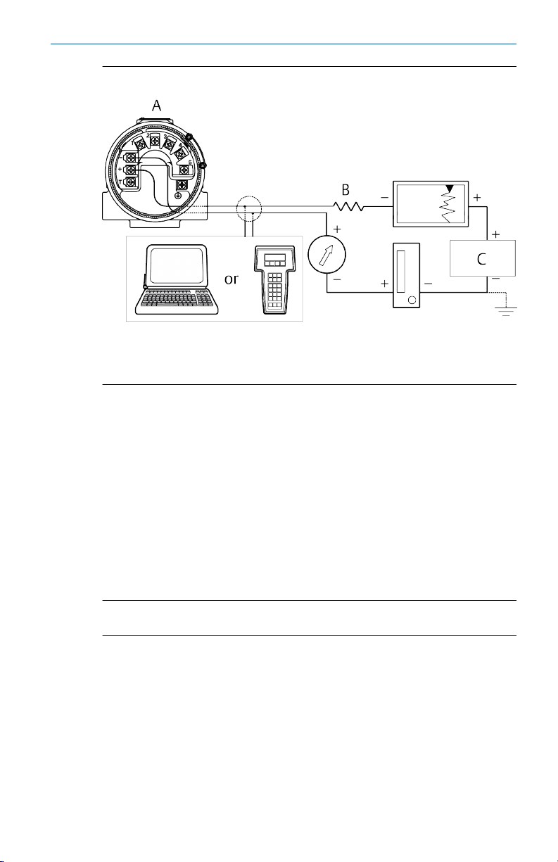
Figure 3-1: Connecting a Communicator to a Bench Loop
A. Power/signal terminals
B. 250 Ω ≤ RL ≤ 1100 Ω
C. Power supply
Procedure
1. Connect the sensor.
See the wiring diagram located on the inside of the housing cover.
2. Connect the bench power supply to the power terminals ("+" or "-").
3. Connect a Field Communicator to the loop across a loop resistor or at
the power/signal terminals on the transmitter.
The following message will appear if the communicator has a previous
version of the device descriptors (DDs):
NOTICE: Upgrade the communicator software to access new XMTR functions.
Continue with old description?
Note
If this notice does not appear, the latest DD is installed.
If the latest version is not available, the communicator will communicate
properly, but when the transmitter is configured some new capabilities may
not be visible.
To prevent this from happening, upgrade to the latest DD or answer NO to
the question and default to the generic transmitter functionality.
Quick Start Guide 7
Page 8

Quick Start Guide March 2021
3.2 Switch HART revision mode
If the HART Protocol configuration tool is not capable of communicating
with HART Revision 7, the transmitter will load a generic menu with limited
capability. The following procedure will switch the HART Revision mode
from the generic menu.
Procedure
Select Manual Setup → Device Information → Identification → Message.
a) To change to HART Revision 5, enter HART5 in the Message field.
b) To change to HART Revision 7, enter HART7 in the Message field.
Function HART 5 Fast Keys HART 7 Fast Keys
2-wire offset sensor 1 2, 2, 1, 5 2, 2, 1, 6
2-wire offset sensor 2 2, 2, 2, 5 2, 2, 2, 6
Alarm values 2, 2, 5, 6 2, 2, 5, 6
Analog calibration 3, 4, 5 3, 4, 5
Analog output 2, 2, 5 2, 2, 5
Average temperature setup 2, 2, 3, 3 2, 2, 3, 3
Burst mode N/A 2, 2, 8, 4
Comm status N/A 1, 2
Configure additional messages N/A 2, 2, 8, 7
Configure Hot Backup
Date 2, 2, 7, 1, 2 2, 2, 7, 1, 3
Descriptor 2, 2, 7, 1, 3 2, 2, 7, 1, 4
Device information 2, 2, 7, 1 2, 2, 7, 1
Differential temperature setup 2, 2, 3, 1 2, 2, 3, 1
Filter 50/60 Hz 2, 2, 7, 5, 1 2, 2, 7, 5, 1
Find device N/A 3, 4, 6, 2
First good temperature setup 2, 2, 3, 2 2, 2, 3, 2
Hardware revision 1, 8, 2, 3 1, 11, 2, 3
HART lock N/A 2, 2, 9, 2
Intermittent sensor detect 2, 2, 7, 5, 2 2, 2, 7, 5, 2
Lock status N/A 1, 11, 3, 7
Long tag N/A 2, 2, 7, 2
™
2, 2, 4, 1, 3 2, 2, 4, 1, 3
8 Rosemount 3144P
Page 9

March 2021 Quick Start Guide
Function HART 5 Fast Keys HART 7 Fast Keys
Loop test 3, 5, 1 3, 5, 1
LRV (lower range value) 2, 2, 5, 5, 3 2, 2, 5, 5, 3
Message 2, 2, 7, 1, 4 2, 2, 7, 1, 5
Open sensor holdoff 2, 2, 7, 4 2, 2, 7, 4
Percent range 2, 2, 5, 4 2, 2, 5, 4
Sensor 1 configuration 2, 2, 1 2, 2, 1
Sensor 1 serial number 2, 2, 1, 7 2, 2, 1, 8
Sensor 1 setup 2, 2, 1 2, 2, 2
Sensor 1 status N/A 2, 2, 1, 2
Sensor 1 type 2, 2, 1, 2 2, 2, 1, 3
Sensor 1 unit 2, 2, 1, 4 2, 2, 1, 5
Sensor 2 configuration 2, 2, 2 2, 2, 2
Sensor 2 serial number 2, 2, 2, 7 2, 2, 2, 8
Sensor 2 setup 2, 2, 2 2, 2, 2
Sensor 2 status N/A 2, 2, 2, 2
Sensor 2 type 2, 2, 2, 2 2, 2, 2, 3
Sensor 2 unit 2, 2, 2, 4 2, 2, 2, 5
Sensor drift alert 2, 2, 4, 2 2, 2, 4, 2
Simulate device variables N/A 3, 5, 2
Software revision 1, 8, 2, 4 1, 11, 2, 4
Tag 2, 2, 7, 1, 1 2, 2, 7, 1, 1
Terminal temperature units 2, 2, 7, 3 2, 2, 7, 3
URV (upper range value) 2, 2, 7, 3 2, 2, 7, 3
Variable mapping 2, 2, 8, 5 2, 2, 8, 5
Thermocouple diagnostic 2, 1, 7, 1 2, 1, 7, 2
Min/max tracking 2, 1, 7, 2 2, 1, 7, 2
Rosemount X-well configuration N/A 2, 2, 1, 11
Quick Start Guide 9
Page 10

Quick Start Guide March 2021
4 Set the switches
The Rosemount 3144P Transmitter comes with hardware switches to
configure alarms and lock the device. Use the following procedures to set
the switches.
WARNING
Enclosure
Enclosure covers must be fully engaged to meet explosion-proof
requirements.
4.1 Set the switches with an LCD display
Procedure
1. Set the loop to manual (if applicable) and disconnect the power.
2. Remove the electronics housing cover.
3. Unscrew the LCD display screws and gently slide the meter straight
off.
4. Set the alarm and security switches to the desired position.
5. Gently slide the LCD display back into place.
6. Replace and tighten the LCD display screws to secure the LCD
display.
7. Reattach housing cover.
8. Apply power and set the loop to automatic control.
4.2
10 Rosemount 3144P
Set the switches without an LCD display
Procedure
1. Set the loop to manual (if applicable) and disconnect the power.
2. Remove the electronics housing cover.
3. Set the alarm and security switches to the desired position.
4. Reattach housing cover.
5. Apply power and set the loop to automatic control.
Page 11

March 2021 Quick Start Guide
5 Mount the transmitter
Mount the transmitter at a high point in the conduit run to prevent moisture
from draining into the transmitter housing.
5.1 Typical North American installation
Procedure
1. Mount the thermowell to the process container wall.
2. Install and tighten thermowells.
3. Perform a leak check.
4. Attach any necessary unions, couplings, and extension fittings. Seal
the fitting threads with an approved thread sealant, such as silicone
or PTFE tape (if required).
5. Screw the sensor into the thermowell or directly into the process
(depending on installation requirements).
6. Verify all sealing requirements.
7. Attach the transmitter to the thermowell/sensor assembly. Seal all
threads with an approved thread sealant, such as silicone or PTFE
tape (if required).
8. Install field wiring conduit into the open transmitter conduit entry
(for remote mounting) and feed wires into the transmitter housing.
9. Pull the field wiring leads into the terminal side of the housing.
10. Attach the sensor leads to the transmitter sensor terminals.
The wiring diagram is located inside the housing cover.
11. Attach and tighten both transmitter covers.
5.2
Quick Start Guide 11
Typical European installation
Procedure
1. Mount the thermowell to the process container wall.
2. Install and tighten thermowells.
3. Perform a leak check.
4. Attach a connection head to the thermowell.
5. Insert sensor into the thermowell and wire the sensor to the
connection head.
The wiring diagram is located inside the connection head.
6. Mount the transmitter to a 2-in. (50 mm) pipe or a panel using one of
the optional mounting brackets.
Page 12

Quick Start Guide March 2021
7. Attach cable glands to the shielded cable running from the
connection head to the transmitter conduit entry.
8. Run the shielded cable from the opposite conduit entry on the
transmitter back to the control room.
9. Insert shielded cable leads through the cable entries into the
connection head/transmitter. Connect and tighten cable glands.
10. Connect the shielded cable leads to the connection head terminals
(located inside the connection head) and to the sensor wiring
terminals (located inside the transmitter housing).
12 Rosemount 3144P
Page 13

March 2021 Quick Start Guide
6 Wire and apply power
6.1 Wire the transmitter
Wiring diagrams are located inside the terminal block cover.
See Table 6-1.
Table 6-1: Single Sensor
2-wire RTD and
ohms
(1) Emerson provides 4-wire sensors for all single-element RTDs. You can use these RTDs in 3-
wire configurations by leaving the unneeded leads disconnected and insulated with
electrical tape.
(2) Transmitter must be configured for a 3-wire RTD in order to recognize an RTD with a
compensation loop.
3-wire RTD and
(1)
ohms
4-wire RTD and
ohms
T/Cs and
millivolts
RTD with
compensation
(2)
loop
Table 6-2: Dual Sensor
Emerson provides 4-wire sensors for all single-element RTDs. To use these RTDs in three-wire
configurations, leave the unneeded leads disconnected and insulated with electrical tape This
table refers to wiring dual sensors for ΔT and Hot Backup™.
With two
RTDs
With two
thermocouples
With RTDs/
thermocouples
With RTDs/
thermocouples
With two RTDs
with
compensation
loop
Quick Start Guide 13
Page 14

Quick Start Guide March 2021
6.2 Power the transmitter
An external power supply is required to operate the transmitter.
A. Sensor terminals (1–5)
B. Power terminals
C. Ground
Procedure
1. Remove the terminal block cover.
2. Connect the positive power lead to the "+" terminal.
3. Connect the negative power lead to the "-" terminal.
4. Tighten the terminal screws.
5. Reattach and tighten the cover.
WARNING
Enclosure
Enclosure covers must be fully engaged to meet explosion-proof
requirements.
6. Apply power.
14 Rosemount 3144P
Page 15

March 2021 Quick Start Guide
6.3 Ground the transmitter
6.3.1 Ungrounded thermocouple, mV, and RTD/ohm inputs
Each process installation has different requirements for grounding. Use the
grounding options recommended by the facility for the specific sensor type
or begin with grounding option 1 (the most common).
Ground the transmitter: option 1
Emerson recommends this option for ungrounded transmitter housing.
Procedure
1. Connect signal wiring shield to the sensor wiring shield.
2. Ensure the two shields are tied together and electrically isolated from
the transmitter housing.
3. Ground shield at the power supply end only.
4. Ensure that the sensor shield is electrically isolated from the
surrounding grounded fixtures.
A. Remote sensor housing
B. Sensor
C. Transmitter
D. Shield ground points
Ground the transmitter: option 2
Emerson recommends this method for grounded transmitter housing.
Procedure
1. Connect sensor wiring shield to the transmitter housing.
Do this only if the housing is grounded.
2. Ensure that the sensor is electrically isolated from surrounding
fixtures that may be grounded.
3. Ground signal wiring shield at the power supply end.
Quick Start Guide 15
Page 16

Quick Start Guide March 2021
A. Remote sensor housing
B. Transmitter
C. Sensor
D. Shield ground parts
Ground the transmitter: option 3
Procedure
1. Ground sensor wiring shield at the sensor, if possible.
2. Ensure the sensor wiring and signal wiring shields are electrically
isolated from the transmitter housing and other grounded fixtures.
3. Ground signal wiring shield at the power supply end.
A. Sensor
B. Transmitter
C. Shield ground points
16 Rosemount 3144P
Page 17

March 2021 Quick Start Guide
6.3.2 Ground thermocouple inputs
Procedure
1. Ground sensor wiring shield at the sensor.
2. Ensure the sensor wiring and signal wiring shields are electrically
isolated from the transmitter housing and other grounded fixtures.
3. Ground signal wiring shield at the power supply end.
A. Sensor wires
B. Transmitter
C. Shield ground point
D. 4–20 mA loop
Quick Start Guide 17
Page 18

Quick Start Guide March 2021
7 Perform a loop test
The loop test verifies transmitter output, loop integrity, and operation of any
recorders or similar devices installed in the loop.
The following procedures are for the device dashboard - device revisions 5
and 7, DD v1.
7.1 Initiate a loop test
Procedure
1. Connect an external ampere meter in series with the transmitter loop
(so the power to the transmitter goes through the meter at some
point in the loop).
2. From the Home screen, select 3 Service Tools → 5 Simulate → 1
Perform Loop Test
The communicator displays the loop test menu.
3. Select a discrete milliampere level for the transmitter to output.
a) At Choose Analog Output, select 1 4 mA or 2 20 mA. If you
want to enter a different value, select 4 Other to manually
input a value between 4 and 20 milliamperes.
b) Select Enter to show the fixed output.
c) Select OK.
4. In the test loop, check that the transmitter's actual mA output and
the HART mA reading are the same value.
If the readings do not match, either the transmitter requires an
output trim or the current meter is malfunctioning.
After completing the test, the display returns to the loop test screen
where you can choose another output value.
5. To end the loop test, select 5 End and Enter.
7.2
18 Rosemount 3144P
Initiate simulation alarm
Procedure
1. From the Home screen, select 3 Service Tools → 5 Simulate → 1
Perform Loop Test → 3 Simulate Alarm.
The transmitter will output the alarm current level based on the
configured alarm parameter and switch settings.
2. Select 5 End to return the transmitter to normal conditions.
Page 19

March 2021 Quick Start Guide
8 Safety Instrumented Systems (SIS)
For safety certified installations, refer to the Rosemount 3144P Reference
Manual. The manual is available electronically on Emerson.com/Rosemount.
You can also contact an Emerson representative for the manual.
Quick Start Guide 19
Page 20

Quick Start Guide March 2021
9 Product certifications
Rev 2.8
9.1 European Directive information
A copy of the EU Declaration of Conformity can be found at the end of this
guide The most recent revision of the EU Declaration of Conformity can be
found at Emerson.com/Rosemount.
9.2 Ordinary location certification
As standard, the device has been examined and tested to determine that the
design meets the basic electrical, mechanical, and fire protection
requirements by a nationally recognized test laboratory (NRTL) as accredited
by the Federal Occupational Safety and Health Administration (OSHA).
9.3 North America
9.3.1 E5 FM Explosionproof, Dust-Ignitionproof, and Nonincendive
Certificate
Standards
Markings
FM16US0202X
FM Class 3600: 2011, FM Class 3611: 2004, FM Class 3615:
2006, FM Class 3810: 2005, ANSI/NEMA 250: 1991, ANSI/ISA
60079-0: 2009, ANSI/ISA 60079-11: 2009
XP CL I, DIV 1, GP A, B, C, D; T5(-50 °C ≤ Ta ≤ +85 °C);
DIP CL II/III, DIV 1, GP E, F, G; T5(-50 °C ≤ Ta ≤ +75 °C); T6(-50
°C ≤ Ta ≤ +60 °C); when installed per Rosemount drawing
03144-0320;
NI CL I, DIV 2, GP A, B, C, D; T5(-60 °C ≤ Ta ≤ +75 °C); T6(-60 °C
≤ Ta ≤+60 °C); when installed per Rosemount drawing
03144-0321, 03144-5075.
9.3.2 I5 FM Intrinsic Safety and Nonincendive
Certificate
Standards
Markings
FM16US0202X
FM Class 3600: 2011, FM Class 3610: 2010, FM Class 3611:
2004, FM Class 3810: 2005, ANSI/NEMA 250: 1991, ANSI/ISA
60079-0: 2009, ANSI/ISA 60079-11: 2009
IS CL I/II/III, DIV 1, GP A, B, C, D, E, F, G; T4(-60 °C ≤ Ta ≤ +60
°C);
IS [Entity] CL I, Zone 0, AEx ia IIC T4(-60 °C ≤ Ta ≤ +60 °C);
NI CL I, DIV 2, GP A, B, C, D; T5(-60 °C ≤ Ta ≤ +75 °C); T6(-60 °C
≤ Ta ≤ +60 °C); when installed per Rosemount drawing
03144-0321, 03144-5075.
20 Rosemount 3144P
Page 21

March 2021 Quick Start Guide
9.3.3 I6 CSA Intrinisic Safety and Division 2
Certificate
Standards
Markings
1242650
CAN/CSA C22.2 No. 0-M91 (R2001), CAN/CSA-C22.2 No. 94M91, CSA Std C22.2 No. 142-M1987, CAN/CSA-C22.2 No.
157-92, CSA Std C22.2 No. 213-M1987
Intrinsically Safe for Class I Groups A, B, C, D; Class II, Groups E,
F, G; Class III;
[HART only zone markings]: Intrinsically Safe for Class I Zone 0
Group IIC; T4(-50 °C ≤ Ta ≤ +60 °C); Type 4X;
Suitable for Class I, Div. 2, Groups A, B, C, D;
[HART only zone markings]: Suitable for Class I Zone 2 Group
IIC; T6(-60 °C ≤ Ta ≤ +60 °C); T5(-60 °C ≤ Ta ≤ +85 °C); when
installed per Rosemount drawing 03144-5076.
9.3.4 K6 CSA Explosionproof, Intrinsic Safety, and Division 2
Certificate
Standards
Markings
1242650
CAN/CSA C22.2 No. 0-M91 (R2001), CSA Std C22.2 No.
25-1966, CSA Std C22.2 No. 30-M1986; CAN/CSA-C22.2 No.
94-M91, CSA Std C22.2 No. 142-M1987, CAN/CSA-C22.2 No.
157-92, CSA Std C22.2 No. 213-M1987
Explosionproof for Class I, Groups A, B, C, D; Class II, Groups E,
F, G; Class III;
[HART only zone markings]: Suitable for Class I Zone 1 Group
IIC; Intrinsically Safe for Class I Groups A, B, C, D; Class II,
Groups E, F, G; Class III;
[HART only zone markings]: Suitable for Class I Zone 0 Group
IIC; T4(-50 °C ≤ Ta ≤ +60 °C); Type 4X; Suitable for Class I, Div.
2, Groups A, B, C, D;
[HART only zone markings]: Suitable for Class I Zone 2 Group
IIC; T6(-60 °C ≤Ta ≤ +60 °C); T5(-60 °C ≤ Ta ≤ +85 °C); when
installed per Rosemount drawing 03144-5076.
9.4 Europe
9.4.1 E1 ATEX Flameproof
Certificate
Standards
Quick Start Guide 21
FM12ATEX0065X
EN 60079-0: 2012+A11:2013, EN 60079-1: 2014, EN
60529:1991 +A1:2000+A2:2013
Page 22

Quick Start Guide March 2021
Markings
II 2 G Ex db IIC T6…T1 Gb, T6(-50 °C ≤ Ta ≤ +40 °C), T5…
T1(-50 °C ≤ Ta ≤ +60 °C);
See Process temperature limits for process temperatures.
Specific Conditions of Use (X):
1. See certificate for ambient temperature range.
2. The non-metallic label may store an electrostatic charge and become
a source of ignition in Group III environments.
3. Guard the LCD display cover against impact energies greater than
four joules.
4. Flameproof joints are not intended for repair.
5. A suitable certified Ex d or Ex tb enclosure is required to be connected
to temperature probes with Enclosure option "N".
6. Care shall be taken by the end user to ensure that the external
surface temperature on the equipment and the neck of DIN Style
Sensor probe does not exceed 266 °F (130 °C).
7. Non-standard paint options may cause risk of electrostatic discharge.
Avoid installations that cause electrostatic build-up on painted
surfaces and only clean the painted surfaces with a damp cloth. If
paint is ordered through a special option code, contact the
manufacturer for more information.
9.4.2 I1 ATEX Intrinsic Safety
Certificate
Standards
Markings
BAS01ATEX1431X [HART]; Baseefa03ATEX0708X [Fieldbus]
EN IEC 60079-0: 2018; EN 60079-11:2012
HART: II 1 G Ex ia IIC T5/T6 Ga; T6(-60 °C ≤ Ta ≤ +50 °C),
T5(-60 °C ≤ Ta ≤ +75 °C)
Fieldbus: II 1 G Ex ia IIC T4 Ga; T4(-60 °C ≤ Ta ≤ +60 °C)
See Table 9-5 for entity parameters.
Special Conditions for Safe Use (X):
1. When fitted with the transient terminal options, the equipment is
not capable of passing the 500 V insulation test. This must be taken
into account during installation.
2. The enclosure may be made from aluminum alloy with a protective
polyurethane paint finish; however, care should be taken to protect it
from impact or abrasion when located in Zone 0.
22 Rosemount 3144P
Page 23

March 2021 Quick Start Guide
9.4.3 N1 ATEX Type n
Certificate
Standards
Markings
Special Condition for Safe Use (X):
1. When fitted with the transient terminal options, the equipment is
BAS01ATEX3432X [HART]; Baseefa03ATEX0709X [Fieldbus]
EN IEC 60079-0:2018, EN 60079-15:2010
HART: II 3 G Ex nA IIC T5/T6 Gc; T6(-40 °C ≤ Ta ≤ +50 °C),
T5(-40 °C ≤ Ta ≤ +75 °C);
Fieldbus: II 3 G Ex nA IIC T5 Gc; T5(-40 °C ≤ Ta ≤ +75 °C);
not capable of passing the 500 V electrical strength test as defined in
clause 6.5.1 of EN 60079-15: 2010. This must be taken into account
during installation.
9.4.4 ND ATEX Dust
Certificate
Standards
Markings
Specific Conditions of Use (X):
1. See certificate for ambient temperature range.
FM12ATEX0065X
EN 60079-0: 2012+A11:2013, EN 60079-31:2014, EN
60529:1991 +A1:2000+A2:2013
See Process temperature limits for process temperature.
II 2 D Ex tb IIIC T130°C Db, (-40 °C ≤ Ta ≤ +70 °C); IP66
2. The non-metallic label may store an electrostatic charge and become
a source of ignition in Group III environments.
3. Guard the LCD display cover against impact energies greater than
four joules.
4. Flameproof joints are not intended for repair.
5. A suitable certified Ex d or Ex tb enclosure is required to be connected
to temperature probes with Enclosure option "N".
6. Care shall be taken by the end user to ensure that the external
surface temperature on the equipment and the neck of DIN Style
Sensor probe does not exceed 266 °F (130 °C).
7. Non-standard paint options may cause risk of electrostatic discharge.
Avoid installations that cause electrostatic build-up on painted
surfaces and only clean the painted surfaces with a damp cloth. If
paint is ordered through a special option code, contact the
manufacturer for more information.
Quick Start Guide 23
Page 24

Quick Start Guide March 2021
9.5 International
9.5.1 E7 IECEx Flameproof
Certificate
Standards
Markings
Specific Conditions of Use (X):
1. See certificate for ambient temperature range.
2. The non-metallic label may store an electrostatic charge and become
3. Guard the LCD display cover against impact energies greater than
4. Flameproof joints are not intended for repair.
5. A suitable certified Ex d or Ex tb enclosure is required to be connected
6. Care shall be taken by the end user to ensure that the external
7. Non-standard paint options may cause risk of electrostatic discharge.
IECEx FMG 12.0022X
IEC 60079-0:2011, IEC 60079-1:2014-06
Ex db IIC T6…T1 Gb, T6(-50 °C ≤ Ta ≤ +40 °C), T5…T1(-50 °C ≤
Ta ≤ +60 °C)
See Process temperature limits for process temperatures.
a source of ignition in Group III environments.
four joules.
to temperature probes with Enclosure option "N".
surface temperature on the equipment and the neck of DIN Style
Sensor probe does not exceed 266 °F (130 °C).
Avoid installations that cause electrostatic build-up on painted
surfaces and only clean the painted surfaces with a damp cloth. If
paint is ordered through a special option code, contact the
manufacturer for more information.
Additionally available with option K7
IECEx Dust
Certificate
Standards
Markings
Specific conditions of use (X):
1. See certificate for ambient temperature range.
24 Rosemount 3144P
IECEx FMG 12.0022X
IEC 60079-0:2011 and IEC 60079-31:2013
Ex tb IIIC T130 °C Db, (-40 °C ≤ Ta ≤ +70 °C); IP66
See Process temperature limits for process temperatures.
Page 25

March 2021 Quick Start Guide
2. The non-metallic label may store an electrostatic charge and become
a source of ignition in Group III environments.
3. Guard the LCD display cover against impact energies greater than
four joules.
4. Flameproof joints are not intended for repair.
5. A suitable certified Ex d or Ex tb enclosure is required to be connected
to temperature probes with Enclosure option "N".
6. Care shall be taken by the end user to ensure that the external
surface temperature on the equipment and the neck of DIN Style
Sensor probe does not exceed 266 °F (130 °C).
7. Non-standard paint options may cause risk of electrostatic discharge.
Avoid installations that cause electrostatic build-up on painted
surfaces and only clean the painted surfaces with a damp cloth. If
paint is ordered through a special option code, contact the
manufacturer for more information.
9.5.2 I7 IECEx Intrinsic Safety
Certificate
Standards
Markings
Special Conditions for Safe Use (X):
1. When fitted with the transient terminal options, the equipment is
2. The enclosure may be made from aluminum alloy with a protective
IECEx BAS 07.0002X [HART]; IECEx BAS 07.0004X [Fieldbus]
IEC 60079-0: 2017; IEC 60079-11: 2011
HART: Ex ia IIC T5/T6 Ga; T6(-60 °C ≤ Ta ≤ +50 °C), T5(-60 °C ≤
Ta ≤ +75 °C);
Fieldbus: Ex ia IIC T4 Ga; T4(-60 °C ≤ Ta ≤ +60 °C)
See Table 9-5 for entity parameters.
not capable of passing the 500 V electrical strength test as defined in
Clause 6.3.13 of IEC 60079-11: 2011. This must be taken into
account during installation.
polyurethane paint finish; however, care should be taken to protect it
from impact or abrasion when located in Zone 0.
9.5.3 N7 IECEx Type n
Certificate
Standards
Markings
IECEx BAS 07.0003X [HART]; IECEx BAS 07.0005X [Fieldbus]
IEC 60079-0:2017, IEC 60079-15:2010
HART: Ex nA IIC T5/T6 Gc; T6(-40 °C ≤ Ta ≤ +50 °C), T5(-40 °C ≤
Ta ≤ +75 °C);
Fieldbus: Ex nA IIC T5 Gc; T5(-40 °C ≤ Ta ≤ +75 °C);
Quick Start Guide 25
Page 26

Quick Start Guide March 2021
Special Condition for Safe Use (X):
1. When fitted with the transient terminal options, the equipment is
not capable of passing the 500 V electrical strength test as defined in
clause 6.5.1 of EN 60079-15: 2010. This must be taken into account
during installation.
9.6 Brazil
9.6.1 E2 INMETRO Flameproof and Dust
Certificate
Standards
Markings
Special Conditions for Safe Use (X):
1. See product description for ambient temperature limits and process
2. The non-metallic label may store an electrostatic charge and become
3. Guard the LCD display cover against impact energies greater than
4. Consult the manufacturer if dimensional information on the
UL-BR 13.0535X
ABNT NBR IEC 60079-0:2013; ABNT NBR IEC 60079-1:2016;
ABNT NBR IEC 60079-31:2014
Ex db IIC T6...T1 Gb; T6(-50 °C ≤ Ta ≤ +40 °C); T5...T1(-50 °C ≤
Ta ≤ +60 °C)
Ex tb IIIC T130 °C Db; IP66; (-40 °C ≤ Ta ≤ +70 °C)
temperature limits.
a source of ignition in Group III environments.
four joules.
flameproof joints is necessary.
9.6.2 I2 INMETRO Intrinsic Safety [HART]
Certificate
Standards
Markings
UL-BR 15.0088X
ABNT NBR IEC 60079-0:2013, ABNT NBR IEC 60079-11:2013
Ex ia IIC T6 Ga (-60 °C < Ta < 50 °C), Ex ia IIC T5 Ga (-60 °C < Ta <
75 °C)
See Table 9-5 for entity parameters.
Special Conditions for Safe Use (X):
1. When fitted with the transient terminal options, the equipment is
not capable of withstanding the 500 V electrical strength test as
defined in ABNT NBR IEC60079-11. This must be taken into account
during installation.
2. The enclosure may be made from aluminum alloy with a protective
polyurethane paint finish; however, care should be taken to protect it
26 Rosemount 3144P
Page 27

March 2021 Quick Start Guide
from impact and abrasion when located in areas that require EPL Ga
(Zone 0).
INMETRO Intrinsic Safety [Fieldbus/FISCO]
Certificate
Standards
Markings
Special Conditions for Safe Use (X):
1. When fitted with the transient terminal options, the equipment is
2. The enclosure may be made from aluminum alloy with a protective
UL-BR 15.0030X
ABNT NBR IEC 60079-0:2013, ABNT NBR IEC 60079-11:2013
Ex ia IIC T4 Ga (-60 °C < Ta < +60 °C)
See Table 9-5 at the end of the Product Certifications section
for Entity Parameters
not capable of withstanding the 500 V electrical strength test as
defined in ABNT NBR IEC60079-11. This must be taken into account
during installation.
polyurethane paint finish; however, care should be taken to protect it
from impact and abrasion when located in areas that require EPL Ga
(Zone 0).
9.7 China
9.7.1 E3 China Flameproof
Certificate
Standards
Markings
9.7.2 I3 China Intrinsic Safety
GYJ16.1339X
GB3836.1-2010, GB3836.2-2010
Ex d IIC T6…T1 Gb
Certificate
Standards
Markings
GYJ16.1338X
GB3836.1-2010, GB3836.4-2010, GB3836.20-2010
Ex ia IIC T4/T5/T6 Ga
9.7.3 N3 China Type n
Certificate
Standards
Markings
Quick Start Guide 27
GYJ20.1086X [Fieldbus]; GYJ20.1091X [HART]
GB3836.1-2010, GB3836.8-2014
Ex nA IIC T5 Gc [Fieldbus]; Ex nA IIC T5/T6 Gc [HART]
Page 28

Quick Start Guide March 2021
Output T code Ambient temperature
Fieldbus T5 -40 °C ≤ Ta ≤ +75 °C
HART T6 -40 °C ≤ Ta ≤ +50 °C
T5 -40 °C ≤ Ta ≤ +75 °C
9.8 EAC - Belarus, Kazakhstan, Russia
9.8.1 EM Technical Regulation Customs Union (EAC) Flameproof
Standards
Markings
Special Condition for Safe Use (X):
1. Non-standard paint options may cause risk of electrostatic discharge.
GOST 31610.0-2014, GOST IEC 60079-1-2013
1Ex db IIC T6…T1 Gb X, T6(-50 °C ≤ Ta ≤ +40 °C), T5…T1(-50 °C
≤ Ta ≤ +60 °C)
See Process temperature limits for process temperatures.
Avoid installations that cause electrostatic build-up on painted
surfaces and only clean the painted surfaces with a damp cloth. If
paint is ordered through a special option code, contact the
manufacturer for more information.
9.8.2 IM Technical Regulation Customs Union (EAC) Intrinsic Safety
Standards
Markings
Special Conditions for Safe Use (X):
1. When fitted with the transient terminal options, the apparatus is not
GOST 31610.0-2014, GOST IEC 60079-11-2014
[HART]: 0Ex ia IIC T5, T6 Ga X, T6(-60 °C ≤ Ta ≤ +50 °C),
T5(-60 °C ≤ Ta ≤ +75 °C);
[Fieldbus/PROFIBUS]: 0Ex ia IIC T4 Ga X, T4(-60 °C ≤ Ta ≤ +60 °C
See Table 9-5 for entity parameters.
capable of withstanding the 500 V electrical strength test as defined
in Clause 6.3.13 of GOST 31610.11-2014. This must be taken into
account during installation.
2. The enclosure may be made from aluminum alloy with a protective
polyurethane paint finish; however, care should be taken to protect it
from impact or abrasion when located in Zone 0.
9.8.3 KM Technical Regulation Customs Union (EAC) Flameproof, Intrinsic Safety, and Dust
Standards
28 Rosemount 3144P
GOST 31610.0-2014, GOST IEC 60079-1-2013, GOST IEC
60079-11-2014, GOST IEC 60079-31-2013
Page 29

March 2021 Quick Start Guide
Markings
Special Condition for Safe Use (X):
1. See certificate for special conditions.
Ex tb IIIC T130 °C Db X (-40 °C ≤ Ta ≤ +70 °C), IP 66 in addition
to markings listed for EM and IM above.
9.9 Japan
9.9.1 E4 Japan Flameproof
Certificate
Markings
Special Conditions for Safe Use:
1. Flameproof joints are not intended for repair.
2. Models with LCD display cover shall have the display cover protected
3. For Models 65 and 185, the user shall ensure the external surface
4. Non-standard paint options may cause risk from electrostatic
5. The wiring used shall be suitable for temperature over 80 °C.
CML 17JPN1316X
Ex d IIC T6…T1 Gb; T6 (-50 °C ≤ Ta ≤ +40 °C); T5...T1 (-50 °C ≤
Ta ≤ +60 °C)
from impact energies greater than 4 Joules.
temperature of the equipment and the neck of the DIN Style probe
does not exceed 130 °C.
discharge.
9.10
Korea
9.10.1 EP Korea Flameproof
Certificate
Markings
Special Condition for Safe Use (X):
1. See certificate for special conditions.
10-KB4BO-0011X
Ex d IIC T6/T5; T6(-40 °C ≤ T
+80 °C)
≤ +70 °C), T5(-40 °C ≤ T
amb
amb
≤
9.10.2 IP Korea Intrinsic Safety
Certificate
Markings
Quick Start Guide 29
09-KB4BO-0028X
Ex ia IIC T6/T5; T6(-60 °C ≤ T
+75 °C)
≤ +50 °C), T5(-60 °C ≤ T
amb
amb
≤
Page 30

Quick Start Guide March 2021
Special Condition for Safe Use (X):
1. See certificate for special conditions.
9.11 Combinations
K1
K2
K5
KB
KP
9.12 Tables
Process temperature limits
Table 9-1: Sensor Only (No Transmitter Installed)
Extension length Process temperature [˚C]
Any extension
length
Table 9-2: Transmitter
Extension length Process temperature [˚C]
No extension 55 70 100 170 280 440 100
3-in. extension 55 70 110 190 300 450 110
6-in. extension 60 70 120 200 300 450 110
9-in. extension 65 75 130 200 300 450 120
Combination of E1, I1, N1, and ND
Combination of E2 and I2
Combination of E5 and I5
Combination of K5, I6, and K6
Combination of EP and IP
Gas Dust
T6 T5 T4 T3 T2 T1 T130 °C
85 100 135 200 300 450 130
Gas Dust
T6 T5 T4 T3 T2 T1 T130 °C
Adhering to the process temperature limitations of Table 9-3 will ensure that
the service temperature limitations of the LCD display cover are not
exceeded. Process temperatures may exceed the limits defined in Table 9-3
if the temperature of the LCD display cover is verified to not exceed the
service temperatures in Table 9-4 and the process temperatures do not
exceed the values specified in Table 9-2.
30 Rosemount 3144P
Page 31

March 2021 Quick Start Guide
Table 9-3: Transmitter with LCD Display Cover
Extension length Process temperature [˚C]
Gas Dust
T6 T5 T4...T1 T130 °C
No extension 55 70 95 95
3-in. extension 55 70 100 100
6-in. extension 60 70 100 100
9-in. extension 65 75 110 110
Table 9-4: Transmitter with LCD Display Cover
Extension length Service temperature [˚C]
Gas Dust
T6 T5 T4...T1 T130 °C
Any extension length 65 75 95 95
Entity parameters
Table 9-5: Entity Parameters
Parameters HART Fieldbus/
PROFIBUS
Voltage Ui (V) 30 30 17.5
Current Ii (mA) 300 300 380
Power Pi (W) 1 1.3 5.32
Capacitance Ci (nF) 5 2.1 2.1
Inductance Li (mH) 0 0 0
FISCO
9.13 Additional certifications
SBS American Bureau of Shipping (ABS) Type Approval
Certificate
Intended use
SBV Bureau Veritas (BV) Type Approval
Certificate
Quick Start Guide 31
16-HS1488352-PDA
Measurement of temperature for marine and offshore
applications
23154
Page 32

Quick Start Guide March 2021
Requirements
Application
Bureau Veritas Rules for the Classification of Steel Ships
Class notations: AUT-UMS, AUT-CCS, AUT-PORT and AUTIMS; Temperature transmitter type 3144P cannot be
installed on diesel engines.
SDN Det Norske Veritas (DNV) Type Approval
Certificate
Intended use
TAA00001JK
Det Norske Veritas’ Rules for Classification of Ships, High
Speed & Light Craft and Det Norske Veritas’ Offshore
Standards
Application
Table 9-6: Location Classes
Temperature D
Humidity B
Vibration A
EMC A
Enclosure D
SLL Lloyds Register (LR) type approval
Certificate
Application
11/60002
Environmental categories ENV1, ENV2, ENV3, and ENV5
32 Rosemount 3144P
Page 33

March 2021 Quick Start Guide
9.14 Installation drawings for intrinsic safety
Quick Start Guide 33
Page 34

Quick Start Guide March 2021
34 Rosemount 3144P
Page 35

March 2021 Quick Start Guide
Quick Start Guide 35
Page 36

Quick Start Guide March 2021
9.15 Declaration of conformity
36 Rosemount 3144P
Page 37

March 2021 Quick Start Guide
Quick Start Guide 37
Page 38

Quick Start Guide March 2021
38 Rosemount 3144P
Page 39

March 2021 Quick Start Guide
9.16 China RoHS
Quick Start Guide 39
Page 40

*00825-0100-4021*
00825-0100-4021, Rev. PB
Quick Start Guide
March 2021
©
2021 Emerson. All rights reserved.
Emerson Terms and Conditions of Sale are
available upon request. The Emerson logo
is a trademark and service mark of
Emerson Electric Co. Rosemount is a mark
of one of the Emerson family of
companies. All other marks are the
property of their respective owners.
 Loading...