

Page 1

Quick Start Guide
00825-0100-4832, Rev CA
Rosemount™ 3095FC MultiVariable™
Mass Flow Transmitter
with Modbus® Protocol
June 2016
Page 2

Quick Start Guide
June 2016
NOTICE
This guide provides basic guidelines for the Rosemount 3095FC with Modbus Protocol. It does not provide
instructions for configuration, diagnostics, maintenance, service, or troubleshooting. Refer to the
Rosemount 3095FC MultiVariable Mass Flow Transmitter Reference Manual
manuals are also available electronically on EmersonProcess.com/Rosemount
for more instruction. The
.
WARNING
Explosions could result in death or serious injury.
Installation of this transmitter in an explosive environment must be in accordance with the appropriate local,
national, and international standards, codes, and practices.
Before connecting communications in an explosive atmosphere, make sure the instruments in the loop
are installed in accordance with intrinsically safe or non-incendive field wiring practices.
In an Explosion-Proof/Flame-Proof installation, do not remove the transmitter covers when power is
applied to the unit.
Process leaks may cause harm or result in death.
To avoid process leaks, only use the o-ring designed to seal with the corresponding flange adapter.
Electrical shock can result in death or serious injury.
Avoid contact with the leads and the terminals. High voltage that may be present on leads can cause
electrical shock.
Contents
Mount the transmitter . . . . . . . . . . . . . . . . . . . . 3
Connect wiring . . . . . . . . . . . . . . . . . . . . . . . . . . . 6
Set jumpers and apply power . . . . . . . . . . . . . . 8
Establish communication . . . . . . . . . . . . . . . . . . 9
2
Verify configuration . . . . . . . . . . . . . . . . . . . . . . 9
Trim the transmitter . . . . . . . . . . . . . . . . . . . . . . 9
Product Certifications . . . . . . . . . . . . . . . . . . . . 11
Page 3

June 2016
Quick Start Guide
1.0 Mount the transmitter
1.1 Installing the Rosemount 3095FC on a pipestand
The following steps must be taken to install the Rosemount 3095FC on a 2-in.
pipestand:
1. Install the pipestand using the pipestand documentation.
2. Remove the orifice/meter run from service.
3. Install the Rosemount 3095FC on a pipestand using clamps or mounting
brackets.
4. Connect the impulse lines.
1.2 Installing the Rosemount 3095FC on an orifice plate (direct
mount)
The following steps must be taken to install the Rosemount 3095FC on an orifice
plate:
1. Remove the orifice/meter run from service.
2. Install the Rosemount 3095FC on the meter run using a manifold and
hardware to secure the Rosemount 3095FC to the orifice flanges.
Figure 1. Gas Flow Application
3
Page 4
Quick Start Guide
A
4 × 1.75-in.
(44 mm)
D
4 × 1.75-in.
(44 mm)
4 × 2.25-in.
(57 mm)
C
4 × 1.75-in.
(44 mm)
4 × 1.50-in.
(38 mm)
B
4 × 2.88-in.
(73 mm)
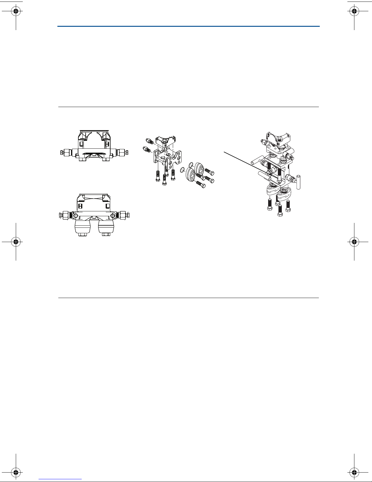
1.3 Bolting considerations
If the transmitter installation requires assembly of the process flanges, manifolds,
or flange adapters, follow these assembly guidelines to ensure a tight seal for
optimal performance characteristics of the transmitters. Use only bolts supplied
with the transmitter or sold by Emerson as spare parts. Figure 2 illustrates
common transmitter assemblies with the bolt length required for proper
transmitter assembly.
Figure 2. Common Transmitter Assemblies
June 2016
A. Transmitter with coplanar flange
B. Transmitter with coplanar flange and optional flange adapters
C. Transmitter with traditional flange and optional flange adapters
D. Transmitter with coplanar flange and optional manifold and flange adapters
Bolts are typically carbon steel or stainless steel. Confirm the material by viewing
the markings on the head of the bolt and referencing Tabl e 1 . If bolt material is
not shown in Tabl e 1 , contact the local Emerson Process Management
representative for more information.
Use the following bolt installation procedure:
1. Carbon steel bolts do not require lubrication and the stainless steel bolts are
coated with a lubricant to ease installation. However, no additional lubricant
should be applied when installing either type of bolt.
2. Finger-tighten the bolts.
3. Torque the bolts to the initial torque value using a crossing pattern. See
Table 1 for initial torque value.
4. Torque the bolts to the final torque value using the same crossing pattern. See
Table 1 for final torque value.
5. Verify that the flange bolts are protruding through the isolator plate before
applying pressure.
4
Page 5

June 2016
B7M
316
316
316
SW
316
STM
316
R
B8M
Table 1. Torque Values for the Flange and Flange Adapter Bolts
Quick Start Guide
Bolt material Head Markings
Carbon Steel (CS)
Stainless Steel (SST) 150 in-lb 300 in-lb
Initial
Tor q ue
300 in-lb 650 in-lb
Final Torque
1.4 O-rings with flange adapters
WARNING
Failure to install proper flange adapter O-rings may cause process leaks, which can result in death or
serious injury. The two flange adapters are distinguished by unique O-ring grooves. Only use the O-ring
that is designed for its specific flange adapter, as shown below:
Rosemount 3051S/3051/2051/3095
A
B
C
D
Rosemount 1151
A
B
C
D
A. Flange adapter
B. O-ring
C. PFTE
D. Elastomer
Whenever the flanges or adapters are removed, visually inspect the o-rings. Replace them if there are any
signs of damage, such as nicks or cuts. If you replace the o-rings, re-torque the flange bolts and alignment
screws after installation to compensate for seating of the PTFE o-ring.
5
Page 6

Quick Start Guide
2.0 Connect wiring
Use the following steps to wire the transmitter:
1. Remove the electronics housing cover on the side marked FIELD TERMINALS.
2. Wire the RTD.
Temperature is input through the Resistance Temperature Detector (RTD)
probe and circuitry. The Rosemount 3095FC provides terminations for a 2- or
3-wire 100-ohm platinum RTD with a IEC 751 curve. The RTD has an alpha (α)
equal to 0.00385.
The RTD mounts directly to the piping using a thermowell. RTD wires should
be protected by a metal sheath or by a conduit connected to a conduit wiring
fitting on the enclosure. The RTD wires connect to the three screw terminals
designated “RTD” on the Termination Board.
Wiring between the RTD and Rosemount 3095FC should be shielded wire,
with the shield grounded only at one end to prevent ground loops. Ground
loops cause RTD input signal errors.
Table 2 displays the RTD terminal connections for the various RTD probes.
June 2016
Table 2. RTD Signal Routing
Ter mi nal Designation 3-wire RTD 2-wire RTD
RTD + Signal positive input RTD + RTD +
RTD + Signal positive input RTD + Jumper to RTD +
RTD RET Return reference RTD RET RTD RET
3. Wire the power supply.
The terminals are labeled CHG+ for positive power connection and CHG- for
negative power connection on a label on the termination board. These
connections provide the input voltage and power for the battery charging
circuit. The maximum voltage that can be applied to the CHG+/CHGterminals is 28 Volts dc.
Pin Signal Description
1 CHG+ Battery 8.0 to 28 V Power
2 CHG- Battery Common
4. Communications wiring
The Local Operator Interface (LOI) port provides direct communications
between the Rosemount 3095FC and the serial port of an operator interface
device, such as an IBM compatible PC using an EIA-232 (RS-232) link. The
interface allows access to the Rosemount 3095FC (using Rosemount User
Interface Software) for configuration and transfer of stored data.
6
Page 7

June 2016
1
6
7
892
3
4
5
To screw
terminals
Connection at PC COM port
White TX
Red TX
Black TX
Connection at LOI port
White TX
Red TX
Black TX
Using the prefabricated operator interface cable, physically connect the
Rosemount 3095FC to the PC running the Rosemount User Interface
Software. One end of the cable (a 9-pin, D-shell, female connector) plugs into
a serial communications port on the PC. The other end of the cable plugs into
the Rosemount 3095FC.
Figure 3. Operator Interface Wiring
Quick Start Guide
Table 3. Local Operator Interface Port Wiring
1. Do not use the LOI to power external devices.
Signal Label
Common COM
LOI Power
(1)
TX + V
Common COM
Ready to Send RTS
Receive RX
Tra ns mi t TX
7
Page 8

Quick Start Guide
A
B
C
D
E
F
G.
H
Figure 4. Rosemount 3095FC Terminal Block and Wiring Diagram
2 OR 3 WIRE RTD
June 2016
OPERATOR
INTERFACE
CABLE
A. LOI
B. RET
C. RTD
D. CHG
LOI
RET
RTD
+
+
+
CHG
POWER
SUPPLY
PC
E. 2 or 3 wire RTD
F. Power supply
G. PC
H. Operator interface cable
3.0 Set jumpers and apply power
To prevent unnecessary battery drainage, the Rosemount 3095FC is delivered
with the reset jumper in the OFF position. To apply power to the Rosemount
3095FC:
1. Complete the necessary wiring.
2. Unscrew the front end cap cover (LCD display end).
3. Place the power jumper in the ON position. The jumper is located on the LCD
display (if installed) or at J1 on the Battery Charger Board.
4. Screw the front-end cap cover (LCD display end).
After the Rosemount 3095FC completes start-up diagnostics (RAM and other
internal checks), the optional LCD display shows the date and time to indicate
that the Rosemount 3095FC completed a valid reset sequence.
8
Page 9

June 2016
Quick Start Guide
4.0 Establish communication
1. Open the Rosemount 3095FC User Interface Software
2. Enter the factory-assigned User ID and Password:
User ID: LOI
Password: 1000
3. Select Direct Connect, located on the software toolbar.
5.0 Verify configuration
1. Select Device > Clock from the menu tab.
2. Verify the correct time and date for the transmitter’s memory logs, and click
OK to exit the screen.
3. Select Device > Information from the menu tab.
4. Verify the correct station name, address number, group number, and contract
hour. Select OK to exit the screen.
5. Select Meter > Set Up from the menu tab.
6. Verify values of pipe and orifice diameter by selecting the General tab.
7. Select Inputs from the top of the screen and verify the correct range and units
of measure for the analog inputs.
8. Select the Gas Quality tab from the top of the screen and verify the correct gas
composition for your process.
9. Select the Advanced tab from the top of the screen. Verify the correct values
for FPV method, units of measure, and all geographical parameters. Select OK
to exit the screen.
6.0 Trim the transmitter
Note
Transmitters are shipped from Emerson™ Process Management, Emerson fully calibrated
per request or by the factory default of full scale.
6.1 Zero trim
A zero trim is a single-point adjustment used for compensating mounting
position effects. When performing a zero trim, ensure the low side block valve is
closed, the equalize valve is open, the high side block valve is open, and all wet
legs are filled to the correct level.
To check or adjust for zero shift, leave the sensor by-pass valve open (to simulate
a no-flow condition), with either line pressure or a normal operating SP from the
calibrator applied to the sensor. This applies the same pressure to both sides of
the DP diaphragm to give a zero DP reading.
9
Page 10

Quick Start Guide
Perform the following steps:
1. Connect the Rosemount User Interface Software to the Rosemount 3095FC
and run the calibration procedure.
2. Select Meter>Calibration >Freeze.
3. Under the Diff Press input, click Zero Shift to open the Set Zero Shift window.
4. Verify Reading to determine if a Zero Sift correction is required.
5. If the reading is not zero, select Set Zero Shift to adjust the Zero and select
Done. If the reading is zero, select Done.
6. Select Done to close the calibration window and cancel the freeze values to
begin using live readings for the flow calculations.
7. Once the zero trim is complete, verify that the high side block valve is open,
close the equalize valve tightly, then open the low side block valve.
June 2016
10
Page 11

June 2016
Quick Start Guide
7.0 Product Certifications
7.1 Approved Manufacturing Locations
Rosemount Inc. — Chanhassen, Minnesota USA
7.2 European Directive Information
The EC declaration of conformity for all applicable European directives for this product can
be found on the Rosemount website at EmersonProcess.com/Rosemount
be obtained by contacting our local sales office.
ATEX Directive (94/9/EC)
Emerson Process Management complies with the ATEX Directive.
European Pressure Equipment Directive (PED) (97/23/EC)
Rosemount 3095F_2/3,4/D Flow Transmitters
— QS Certificate of Assessment - EC No. PED-H-100 Module H Conformity Assessment
All other 3095_ Transmitters/Level Controller
— Sound Engineering Practice
. A hard copy may
Transmitter Attachments: Process Flange - Manifold
— Sound Engineering Practice
Electro Magnetic Compatibility (EMC) (2004/108/EC)
Rosemount 3095F Flow Transmitters - EN 61326-1:1997 - A1, A2, and A3
Ordinary Location Certification for Factory Mutual
As standard, the Rosemount 3095FB Transmitter has been examined and tested to
determine that the design meets basic electrical, mechanical, and fire protection
requirements by FM, a nationally recognized testing laboratory (NRTL) as accredited by the
Federal Occupational Safety and Health Administration (OSHA).
7.3 Hazardous Locations Certifications
North American Certifications
Canadian Standards Association (CSA) - U.S. and Canada
M Explosion-Proof for Class I, Division 1, Groups C and D including optional solar panel:
mast option: Suitable for use in Class I, Division 2, Groups A, B, C, D, and T3. CSA
Enclosure Type 4.
European Certifications
H ATEX Flame4proof
Certificate: LCIE05ATEX6057X II 2 G
EEx d IIB T5
V
= 28V dc
max
IP66
1180
Special Conditions for Safe Use (x):
1. Operating ambient temperature: –40 °C to 75 °C.
2. The users have to make sure that the thermal fluid transfer doesn’t overheat the
equipment to a temperature corresponding to the spontaneous combustion
temperature of surrounding gas.
11
Page 12

Quick Start Guide
Figure 5. Rosemount 3095FC Declaration of Conformity
June 2016
12
Page 13

June 2016
Quick Start Guide
13
Page 14

Quick Start Guide
June 2016
14
Page 15

June 2016
Quick Start Guide
15
Page 16

Quick Start Guide
ᴹ
China RoHS
㇑᧗⢙䍘䎵䗷ᴰབྷ⎃ᓖ䲀٬Ⲵ䜘Ԧරࡇ㺘
Rosemount 3095FC
List of Rosemount 3095FC Parts with China RoHS Concentration above MCVs
䜘Ԧ〠
Part Name
ᴹᇣ⢙䍘䍘
/ Hazardous Substances
䫵
Lead
(Pb)
⊎
Mercury
(Hg)
䭹
Cadmium
(Cd)
ޝԧ䬜䬜
Hexavalent
Chromium
(Cr +6)
ཊⓤ㚄㚄㤟
Polybrominated
biphenyls
(PBB)
ཊⓤ㚄㚄㤟䟊
Polybrominated
diphenyl ethers
(PBDE)
⭥ᆀ㓴Ԧ
Electronics
Assembly
XO O O O O
༣փ㓴Ԧ
Housing
Assembly
XO O X O O
Րᝏಘ㓴Ԧ
Sensor
Assembly
XO O X O O
ᵜ㺘Ṭ㌫ᦞ
SJ/T11364
Ⲵ㿴ᇊ㘼ࡦ
This table is proposed in accordance with the provision of SJ/T11364.
O:
Ѫ䈕䜘ԦⲴᡰᴹ൷䍘ᶀᯉѝ䈕ᴹᇣ⢙䍘Ⲵ䟿൷վҾ
GB/T 26572
ᡰ㿴ᇊⲴ䲀䟿㾱≲
O: Indicate that said hazardous substance in all of the homogeneous materials for this part is below the limit requirement of
GB/T 26572.
X:
Ѫ൘䈕䜘Ԧᡰ֯⭘Ⲵᡰᴹ൷䍘ᶀᯉ䟼ˈ㠣ቁᴹа㊫൷䍘ᶀᯉѝ䈕ᴹᇣ⢙䍘Ⲵ䟿儈Ҿ
GB/T 26572
ᡰ㿴ᇊⲴ䲀䟿㾱≲
X: Indicate that said hazardous substance contained in at least one of the homogeneous materials used for this part is above
the limit requirement of GB/T 26572.
June 2016
16
Page 17

June 2016
Quick Start Guide
17
Page 18

*00825-0100-4832*
Quick Start Guide
00825-0100-4832, Rev CA
June 2016
Global Headquarters
Emerson Process Management
6021 Innovation Blvd.
Shakopee, MN 55379, USA
+1 800 999 9307 or +1 952 906 8888
+1 952 949 7001
RFQ.RMD-RCC@EmersonProcess.com
North America Regional Office
Emerson Process Management
8200 Market Blvd.
Chanhassen, MN 55317, USA
+1 800 999 9307 or +1 952 906 8888
+1 952 949 7001
RMT-NA.RCCRFQ@Emerson.com
Latin America Regional Office
Emerson Process Management
1300 Concord Terrace, Suite 400
Sunrise, FL 33323, USA
+1 954 846 5030
+1 954 846 5121
RFQ.RMD-RCC@EmersonProcess.com Linkedin.com/company/Emerson-Process-Management
Europe Regional Office
Emerson Process Management Europe GmbH
Neuhofstrasse 19a P.O. Box 1046
CH 6340 Baar
Switzerland
+41 (0) 41 768 6111
+41 (0) 41 768 6300
RFQ.RMD-RCC@EmersonProcess.com
Asia Pacific Regional Office
Emerson Process Management Asia Pacific Pte Ltd
1 Pandan Crescent
Singapore 128461
+65 6777 8211
+65 6777 0947
Enquiries@AP.EmersonProcess.com
Middle East and Africa Regional Office
Emerson Process Management
Emerson FZE P.O. Box 17033,
Jebel Ali Free Zone - South 2
Dubai, United Arab Emirates
+971 4 8118100
+971 4 8865465
RFQ.RMTMEA@Emerson.com
Twitter.com/Rosemount_News
Facebook.com/Rosemount
Youtube.com/ user/RosemountMeasurement
Google.com/+RosemountMeasurement
Standard Terms and Conditions of Sale can be found at
www.Emerson.com/en-us/pages/Terms-of-Use.aspx
The Emerson logo is a trademark and service mark of Emerson
Electric Co.
MultiVariable, Rosemount, and Rosemount logotype are
trademarks of Emerson Process Management.
Modbus is a registered trademark of Gould Inc.
All other marks are the property of their respective owners.
© 2016 Emerson Process Management. All rights reserved.
 Loading...