

Emerson Rosemount 3051SMV WirelessHART, Rosemount 3051SF WirelessHART, Rosemount 300SMV WirelessHART, Rosemount 300S WirelessHART, Rosemount 3051S WirelessHART Quick Start Manual
Quick Start Guide
00825-0200-4802, Rev HE
February 2019
Rosemount™ 3051S Series Pressure
Transmitter and Rosemount 3051SF
Series Flowmeter
with WirelessHART® Protocol

Quick Start Guide February 2019
Safety messages
NOTICE
This guide provides basic guidelines for Rosemount™ 3051S and 3051S MultiVariable™ Wireless
Transmitters. It does not provide instructions for diagnostics, maintenance, service, or
troubleshooting. Refer to the Rosemount 3051S and 3051S MultiVariable Wireless Reference Manual
for more instruction.This document is also available electronically on Emerson.com/Rosemount.
WARNING
Explosions could result in death or serious injury.
Installation of device in an explosive environment must be in accordance with appropriate local,
national, and international standards, codes, and practices.
Review Rosemount 3051S and 3051SMV Wireless Product Certifications of this guide for any
restrictions associated with a safe installation.
• Before connecting a handheld communicator in an explosive atmosphere, make sure the
instruments in the loop are installed in accordance with intrinsically safe or non-incendive field
wiring practices.
Electrical shock could cause death or serious injury.
• Avoid contact with the leads and terminals. High voltage that may be present on leads can cause
electrical shock.
This device complies with Part 15 of the FCC Rules. Operation is subject to the following conditions:
• This device may not cause harmful interference.
• This device must accept any interference received, including interference that may cause
undesired operation.
• This device must be installed to ensure a minimum antenna separation distance of 20 cm (8 in.)
from all persons.
Power module considerations.
• The power module may be replaced in a hazardous area. The power module has surface resistivity
greater than one gigaohm and must be properly installed in the wireless device enclosure. Care
must be taken during transportation to and from the point of installation to prevent electrostatic
charge build-up.
CAUTION
Shipping considerations for wireless products.
The unit was shipped to you without the power module installed. Remove the power module prior to
shipping.
Each power module contains two “C” size primary lithium batteries. Primary lithium batteries are
regulated in transportation by the U. S. Department of Transportation, and are also covered by IATA
(International Air Transport Association), ICAO (International Civil Aviation Organization), and ARD
(European Ground Transportation of Dangerous Goods). It is the responsibility of the shipper to ensure
compliance with these or any other local requirements. Consult current regulations and requirements
before shipping.
2 Rosemount 3051S Wireless

February 2019 Quick Start Guide
Contents
Wireless considerations................................. 5
Mount the transmitter................................... 7
Connect the power module......................... 18
Trim the transmitter.................................... 19
Close the housing........................................ 20
Verify operation........................................... 21
Reference information................................. 24
Rosemount 3051S and 3051SMV Wireless
Product Certifications.................................. 25
Quick Start Guide 3

Quick Start Guide February 2019
4 Rosemount 3051S Wireless
February 2019 Quick Start Guide
1 Wireless considerations
1.1 Power up sequence
The Wireless Gateway should be installed and functioning properly before any
wireless field devices are powered. Install the Black Power Module,
SmartPower™ Solutions model number 701PBKKF (part number
00753-9220-0001) into the Rosemount 702 Transmitter to power the device.
Wireless devices should be powered up in order of proximity from the
Gateway, beginning with the closest device, then working outward from the
Gateway. This results in a simpler and faster network installation. Enable
Active Advertising on the Gateway to ensure new devices are able to join the
network faster. For more information see the Emerson™ Wireless 1420
Gateway Reference Manual.
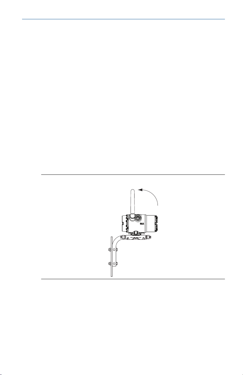
1.2 Antenna position
The antenna should be positioned vertically, either straight up or straight
down, and it should be approximately 3 ft. (1 m) from any large structure,
building, or conductive surface to allow for clear communication to other
devices.
Figure 1-1: Antenna Position
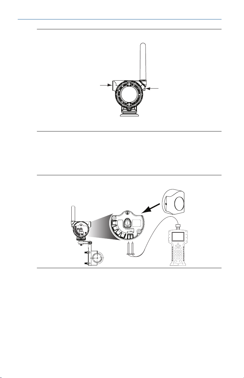
1.3 Conduit entry
Upon installation, ensure each conduit entry is either sealed with a conduit
plug using approved thread sealant, or has an installed conduit fitting or cable
gland with appropriate threaded sealant. Note the conduit entries on the
Emerson 781 Field Link are threaded ½–14 NPT.
Quick Start Guide 5
$
$
COMM
P/N 00753-9200-0020
1
2
3
4
CH1 +
CMN
CH2 +
CMN
CH Input Mode:
Dry Contact Only
CH Output Mode:
26VDC Max
100mA Max
Quick Start Guide February 2019
Figure 1-2: Conduit Entry
A. Conduit entry
1.4 Field Communicator connections
The power module needs to be installed before the Field Communicator can
interface with the transmitter. This transmitter uses the Black Power Module;
Order model number 701PBKKF or part number 00753-9220-0001.
Figure 1-3: Connection Diagram
The transmitter and all other wireless devices should not be set up until after
the Wireless Gateway has been installed and is functioning properly.
6 Rosemount 3051S Wireless

A
A
February 2019 Quick Start Guide
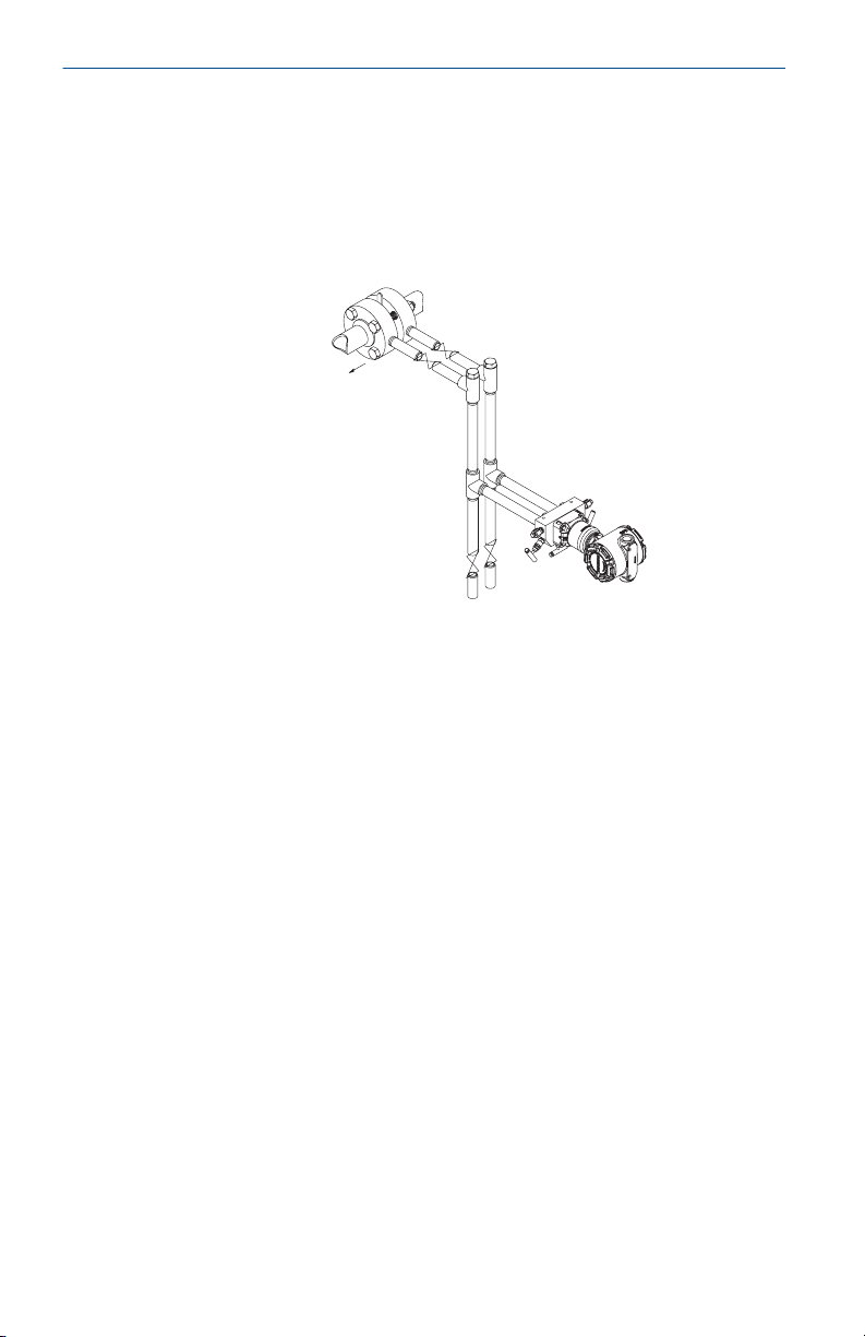
2 Mount the transmitter
2.1 Liquid flow applications
Procedure
1. Place taps to the side of the line.
2. Mount beside or below the taps.
3. Mount the transmitter so that the drain/vent valves are oriented
upward.
A. Direction of flow
2.2 Gas flow applications
Procedure
1. Place taps in the top or side of the line.
2. Mount beside or above the taps.
A. Direction of flow
Quick Start Guide 7
A
Quick Start Guide February 2019
2.3 Steam flow applications
Procedure
1. Place taps to the side of the line.
2. Mount beside or below the taps.
3. Fill impulse lines with water.
A. Direction of flow
8 Rosemount 3051S Wireless

February 2019 Quick Start Guide
2.4 Mounting options
Panel mounting
Figure 2-1: Coplanar Flange
Figure 2-2: Traditional Flange
Quick Start Guide 9

3.08
(78)
A
6.25
(158)
Quick Start Guide February 2019
Figure 2-3: In-line Device
A. U-bolt bracket
Pipe mounting
Figure 2-4: Coplanar Flange
10 Rosemount 3051S Wireless
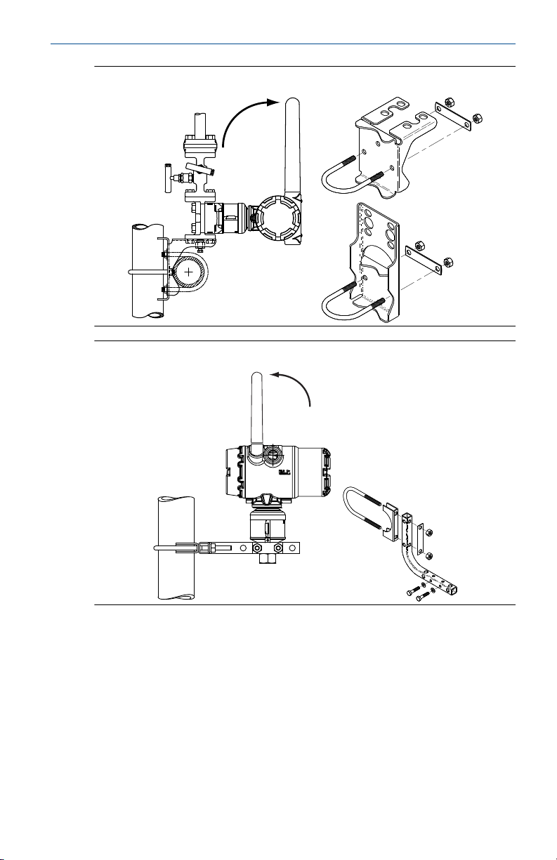
February 2019 Quick Start Guide
Figure 2-5: Traditional Flange
Figure 2-6: In-line Device
2.5 Bolting considerations
If the transmitter installation requires assembly of a process flange, manifold,
or flange adapters, follow these assembly guidelines to ensure a tight seal for
optimal performance characteristics of the transmitter. Only use bolts
supplied with the transmitter or sold by Emerson™ as spare parts. Figure 2-7
illustrates common transmitter assemblies with the bolt length required for
proper transmitter assembly.
Quick Start Guide 11
 Loading...