

Emerson Rosemount 3051SF Series, Rosemount 3051SFA, Rosemount 3051S Series, Rosemount 3051SFP, Rosemount 3051SFC Quick Start Manual

Quick Start Guide
00825-0100-4801, Rev NB
December 2018
Rosemount™ 3051S Series Pressure
Transmitter and Rosemount 3051SF
Series Flowmeter
with HART® Protocol

Safety messages
NOTICE
This guide provides basic guidelines for Rosemount™ 3051S Series Pressure Transmitters. It also
provides the basic electronic guidelines for the Rosemount 3051SFA Reference Manual, Rosemount
3051SFC Reference Manual, and Rosemount 3051SFP Reference Manual. It does not provide
instructions for diagnostics, maintenance, service, or troubleshooting. Refer to the Rosemount 3051S
HART Reference Manual for more instruction. This document is also available electronically on
Emerson.com/Rosemount.
WARNING
Explosions could result in death or serious injury.
Installation of device in an explosive environment must be in accordance with appropriate local,
national, and international standards, codes, and practices.
Review the Rosemount 3051S/3051SFx/3051S-ERS Product Certifications section of this guide for any
restrictions associated with a safe installation.
• Before connecting a handheld communicator in an explosive atmosphere, make sure the
instruments in the loop are installed in accordance with intrinsically safe or non-incendive field
wiring practices.
• In an explosion-proof/flameproof installation, do not remove the transmitter covers when power
is applied to the unit.
• Use appropriately rated Ex adaptors, blanking elements, or glands during installation.
• Keep process insulation at least 1 inch (25 mm) from transmitter connection.
Process leaks could result in death or serious injury.
• Install and tighten process connectors before applying pressure.
Electrical shock could cause death or serious injury.
• Avoid contact with the leads and terminals. High voltage that may be present on leads can cause
electrical shock.
Conduit/cable entries
• Unless marked, the conduit/cable entries in the transmitter housing use a ½–14 NPT thread form.
Entries marked “M20” are M20 × 1.5 thread form. On devices with multiple conduit entries, all
entries will have the same thread form. Only use plugs, adapters, glands, or conduit with a
compatible thread form when closing these entries.
• When installing in a hazardous location, use only appropriately listed or Ex certified plugs, glands,
or adapters in cable/conduit entries.
Contents
Mount the transmitter................................... 5
Consider housing rotation............................11
Set switches and jumpers.............................12
Connect wiring and power up...................... 14
Verify configuration..................................... 22
Trim the transmitter.................................... 26
Safety instrumented systems installation.....28
Rosemount 3051S/3051SFx/3051S-ERS
Product Certifications.................................. 29
Quick Start Guide December 2018
2 Rosemount 3051S

Rosemount 3051S Declaration of Conformity
.................................................................... 45
China RoHS.................................................. 49
December 2018 Quick Start Guide
Quick Start Guide 3

Quick Start Guide December 2018
4 Rosemount 3051S
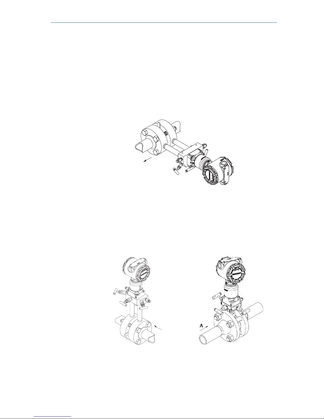
1 Mount the transmitter
1.1 Liquid flow applications
Procedure
1. Place taps to the side of the line.
2. Mount beside or below the taps.
3. Mount the transmitter so that the drain/vent valves are oriented
upward.
A
A. Direction of flow
1.2 Gas flow applications
Procedure
1. Place taps in the top or side of the line.
2. Mount beside or above the taps.
A
A. Direction of flow
December 2018 Quick Start Guide
Quick Start Guide 5
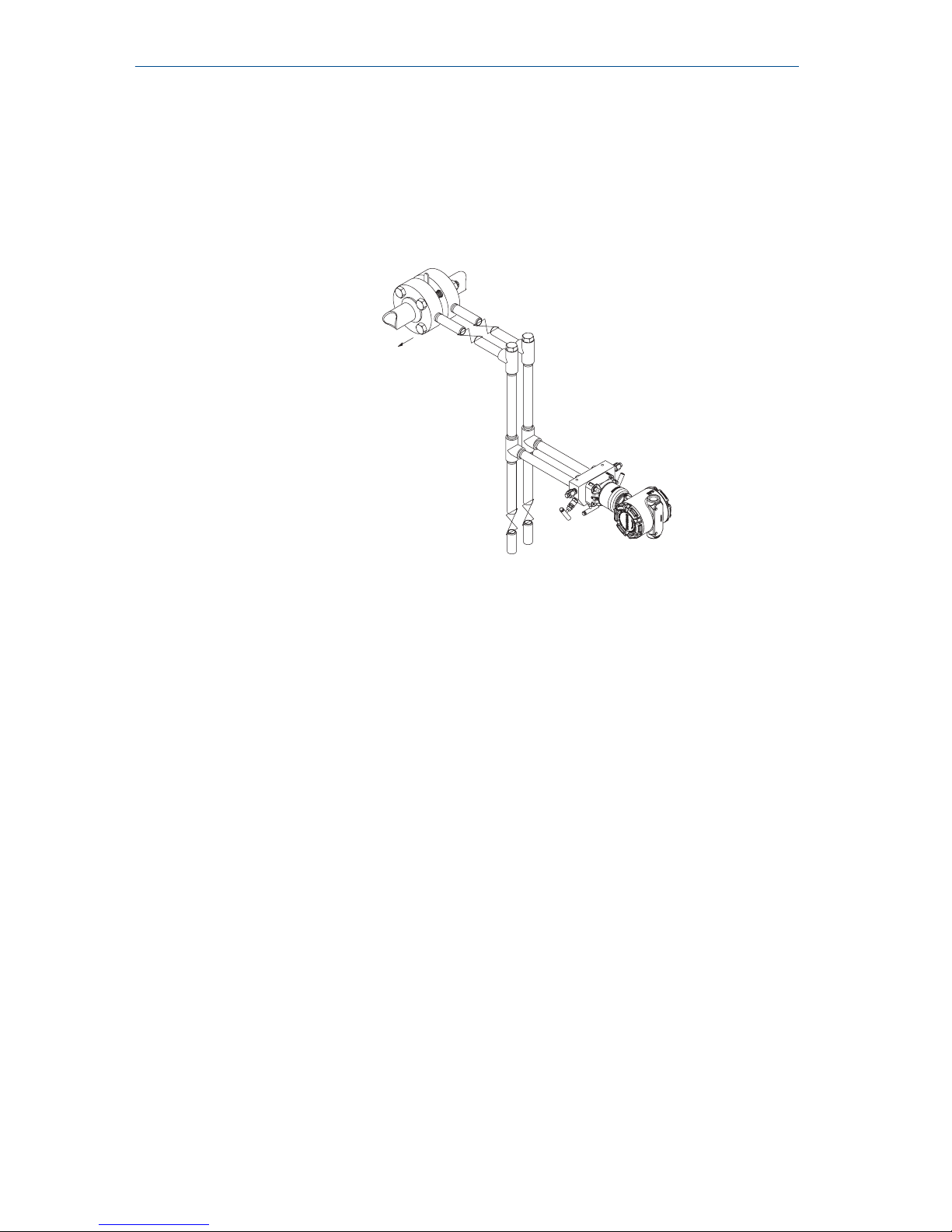
1.3 Steam flow applications
Procedure
1. Place taps to the side of the line.
2. Mount beside or below the taps.
3. Fill impulse lines with water.
A
A. Direction of flow
1.4 Using a mounting bracket
If the transmitter requires the use of a mounting bracket, use the images
below for instructions on how to properly mount the transmitter using the
Emerson™ provided mounting brackets. Use only bolts provided with the
transmitter or sold as Emerson spare parts.
1.5
Bolting considerations
About this task
If the transmitter installation requires assembly of a process flange, manifold,
or flange adapters, follow these assembly guidelines to ensure a tight seal for
optimal performance characteristics of the transmitter. Only use bolts
supplied with the transmitter or sold by Emerson™ as spare parts. Figure 1-1
illustrates common transmitter assemblies with the bolt length required for
proper transmitter assembly.
Quick Start Guide December 2018
6 Rosemount 3051S
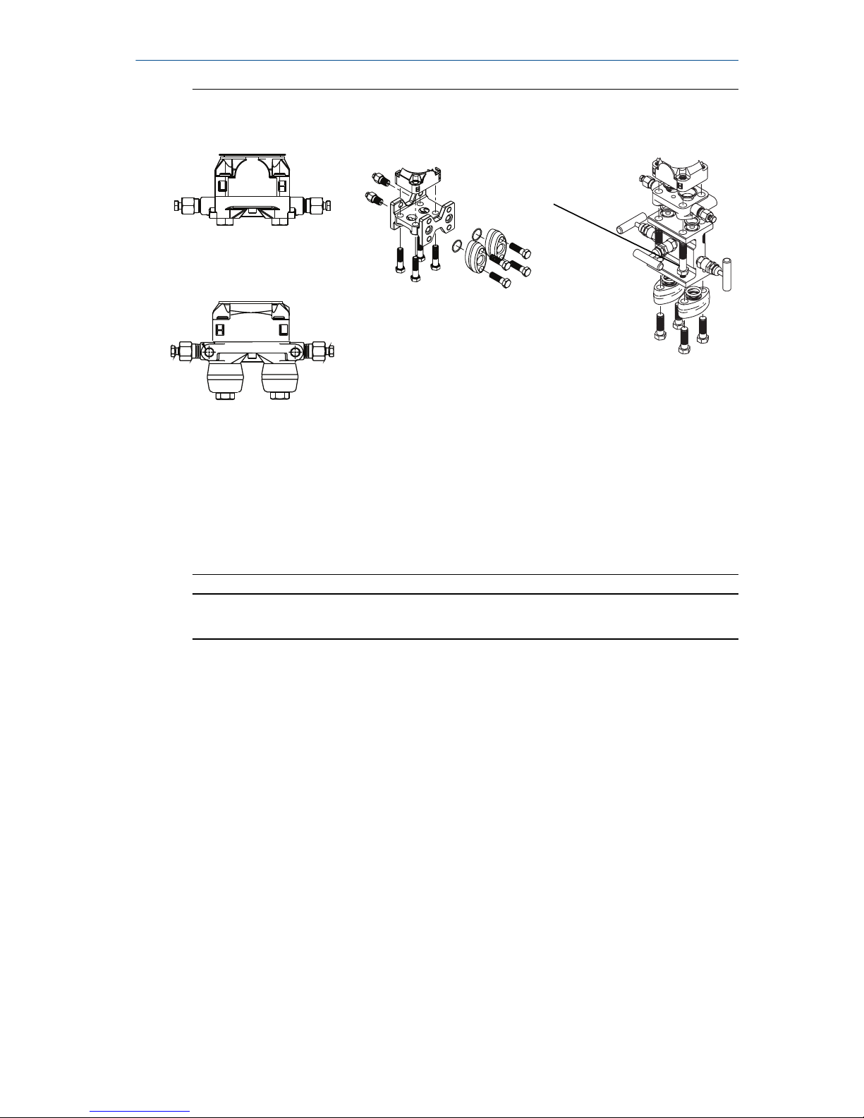
Figure 1-1: Common Transmitter Assemblies
A
4 × 1.75-in.
(44 mm)
D
4 × 1.75-in.
(44 mm)
4 × 2.25-in.
(57 mm)
C
4 × 1.75-in.
(44 mm)
4
× 1.50-in.
(38 mm)
B
4 × 2.88-in.
(73 mm)
A. Transmitter with coplanar flange
B. Transmitter with coplanar flange and optional flange adapters
C. Transmitter with traditional flange and optional flange adapters
D. Transmitter with coplanar flange and optional Rosemount Conventional
Manifold and flange adapters
Note
For all other manifolds, contact Customer Central technical support.
Bolts are typically carbon steel or stainless steel. Confirm the material by
viewing the markings on the head of the bolt and referencing Table 1-1 . If
bolt material is not shown in Table 1-1, contact the local Emerson
representative for more information.
Use the following bolt installation procedure:
Procedure
1. Carbon steel bolts do not require lubrication and the stainless steel
bolts are coated with a lubricant to ease installation. However, no
additional lubricant should be applied when installing either type of
bolt.
2. Finger-tighten the bolts.
3. Torque the bolts to the initial torque value using a crossing pattern.
See Table 1-1 for initial torque value.
4. Torque the bolts to the final torque value using the same crossing
pattern. See Table 1-1 for final torque value.
December 2018 Quick Start Guide
Quick Start Guide 7
5. Verify the flange bolts are protruding through the sensor module
before applying pressure (see Figure 1-2).
Example
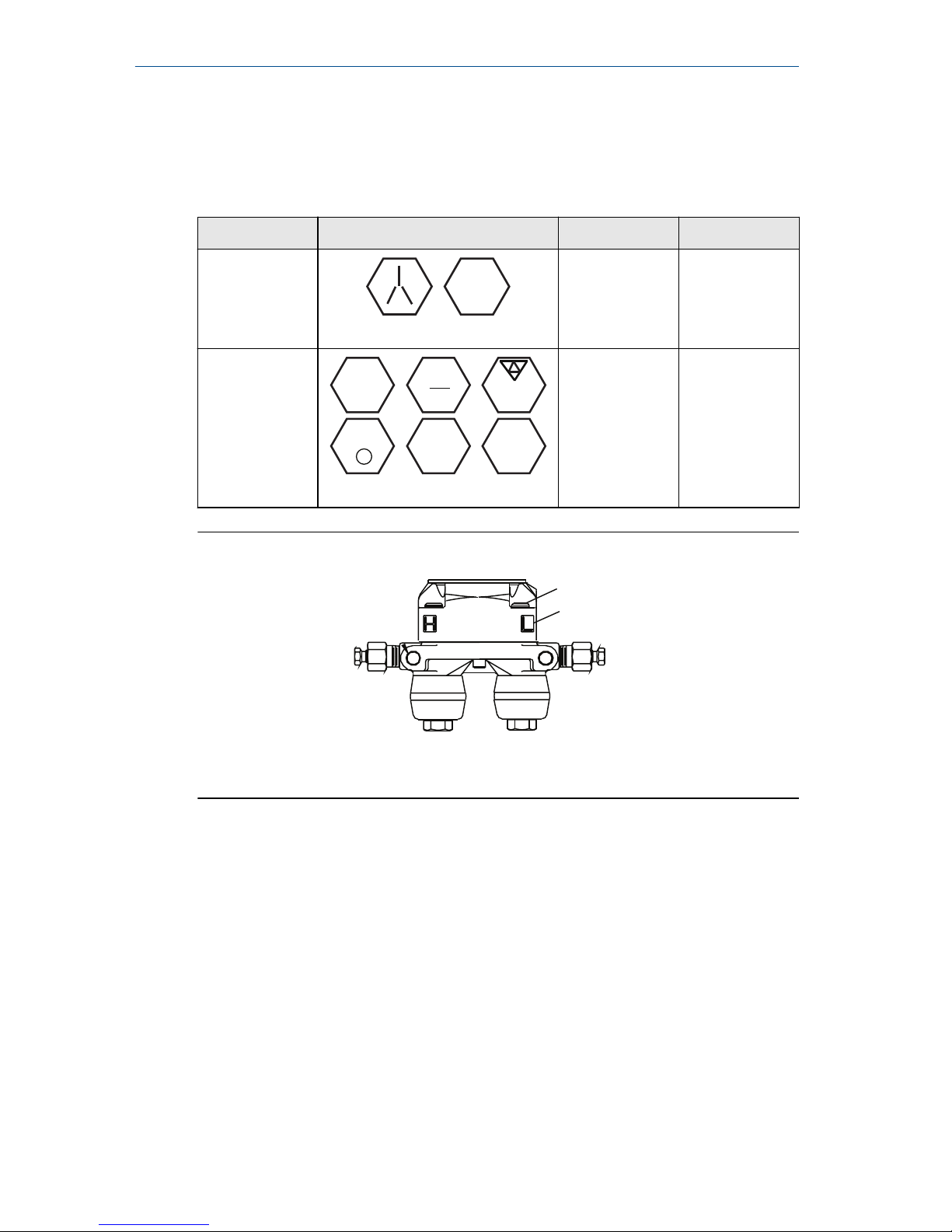
Table 1-1: Torque Values for the Flange and Flange Adapter Bolts
Bolt material Head markings Initial torque Final torque
Carbon Steel
(CS)
B7M
300 in-lb 650 in-lb
Stainless Steel
(SST)
316
316
316
SW
316
STM
316
R
B8M
150 in-lb 300 in-lb
Figure 1-2: Proper Bolt Installation
A
B
A. Bolt
B. Sensor module
Quick Start Guide December 2018
8 Rosemount 3051S
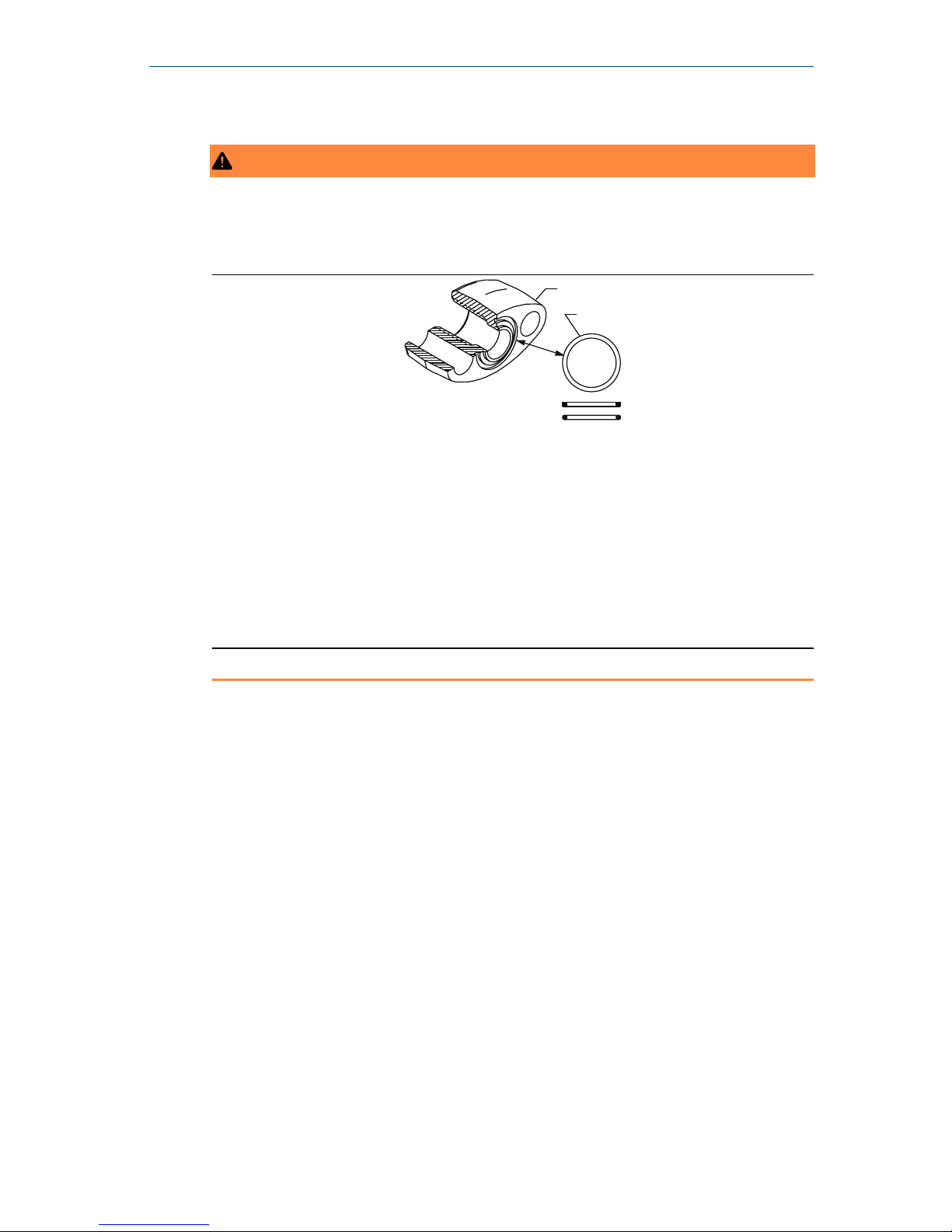
1.6 O-rings with flange adapters
WARNING
Failure to install proper flange adapter O-rings may cause process leaks, which
can result in death or serious injury. Only use the O-ring that is designed for its
specific flange adapter.
A
B
C
D
A. Flange adapter
B. O-ring
C. PTFE-based profile (square)
D. Elastomer profile (round)
Whenever the flange or adapters are removed, visually inspect the O-rings.
Replace them if there are any signs of damage, such as nicks or cuts. If the Orings are replaced, re-torque the flange bolts and alignment screws after
installation to compensate for seating of the O-rings.
1.7
In-line gage transmitter orientation
The low side pressure port (atmospheric reference) on the in-line gage
transmitter is located under the sensor module neck label. (See Figure 1-3)
Keep the vent path free of any obstruction, including but not limited to paint,
dust, and lubrication by mounting the transmitter so that any contaminants
can drain away.
December 2018 Quick Start Guide
Quick Start Guide 9
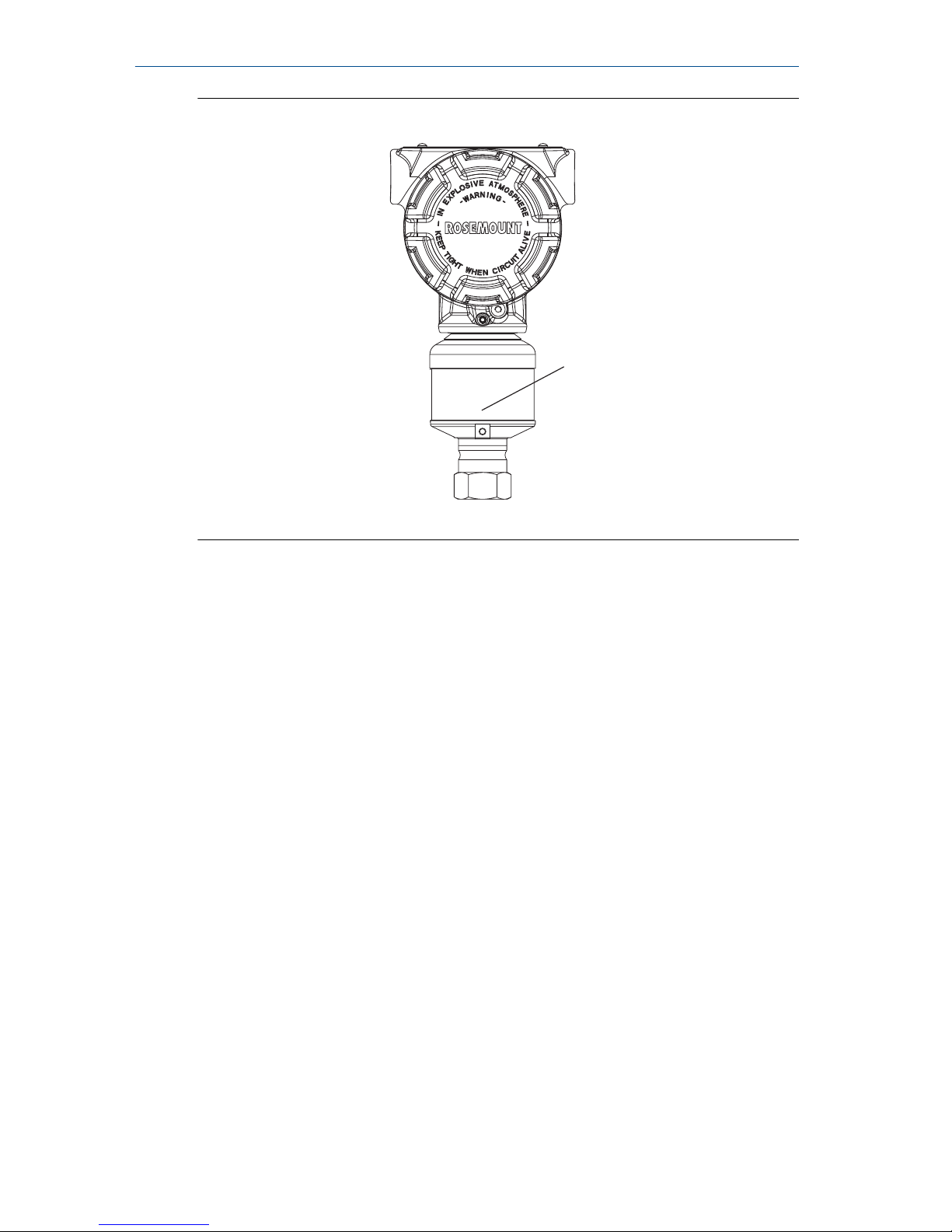
Figure 1-3: In-line Gage Transmitter
A
A. Low side pressure port (under neck label)
Quick Start Guide December 2018
10 Rosemount 3051S

2 Consider housing rotation
About this task
To improve field access to wiring or to better view the optional LCD display:
Procedure
1. Loosen the housing rotation set screw.
2. Turn the housing up to 180° left or right of its original (as shipped)
position.
3. Re-tighten the housing rotation set screw.
Figure 2-1: Transmitter Housing Set Screw
A. LCD display
B. Housing rotation set screw (3/32-in.)
CAUTION
Do not rotate the housing more than 180° without first performing a
disassembly procedure. Over-rotation may sever the electrical
connection between the sensor module and the electronics.
December 2018 Quick Start Guide
Quick Start Guide 11

3 Set switches and jumpers
About this task
If alarm and security adjustment option is not installed, the transmitter will
operate normally with the default alarm condition alarm “high” and the
security “off”.
Procedure
1. Do not remove the transmitter covers in explosive atmospheres when
the circuit is live. If the transmitters is live, set the loop to manual and
remove power.
2. Remove the electronics compartment cover. On the Plantweb housing
the cover is opposite the field terminals side, or on the junction box
housing remove the terminal block cover. Do not remove the housing
cover in explosive environments.
3. On the Plantweb housing, slide the security and alarm switches into
the preferred position by using a small screwdriver (An LCD display or
an adjustment module must be in place to activate the switches). On
the junction box housing pull the pins out and rotate 90° into desired
position to set the security and alarm.
4. Reinstall the housing cover so metal contacts metal to meet explosionproof requirements.
Figure 3-1: Transmitter Switch and Jumper Configuration
(Plantweb)
A
B
C
A. Meter/adjustment module
B. Security
C. Alarm
Quick Start Guide December 2018
12 Rosemount 3051S
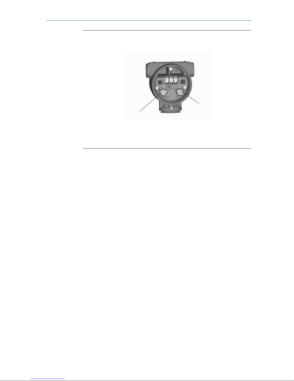
Figure 3-2: Transmitter Switch and Jumper Configuration (Junction
Box)
B
C
A. Meter/adjustment module
B. Security
C. Alarm
December 2018 Quick Start Guide
Quick Start Guide 13

4 Connect wiring and power up
Procedure
1. Remove and discard orange conduit plugs.
2. Remove the housing cover labeled “Field Terminals.”
Note
Do not connect the power across the test terminals. Power could
damage the test diode in the test connection. Twisted pairs yield best
results. Use 24–14 AWG wire and do not exceed 5,000 ft. (1,500 m).
For single compartment housing (Junction Box housing), shielded
signal wiring should be used in high EMI/RFI environments.
3. Connect the positive lead to the “+” terminal, and the negative lead to
the “–” terminal.
4. CAUTION
When the enclosed threaded plug is utilized in the conduit opening, it
must be installed with a minimum thread engagement in order to
comply with explosion-proof requirements. For straight threads, a
minimum of seven threads must be engaged. For tapered threads, a
minimum of five threads must be engaged.
Plug and seal the unused conduit connection with the provided
conduit plug.
5. If applicable, install wiring with a drip loop. Arrange the drip loop
so the bottom is lower than the conduit connections and the
transmitter housing.
6. Reinstall the housing cover and tighten so the cover is fully seated with
metal to metal contact between the housing and cover in order to
meet explosion proof requirements.
The figures below show the wiring connections necessary to power a
transmitter and enable communications with a hand-held Field
Communicator.
Quick Start Guide December 2018
14 Rosemount 3051S
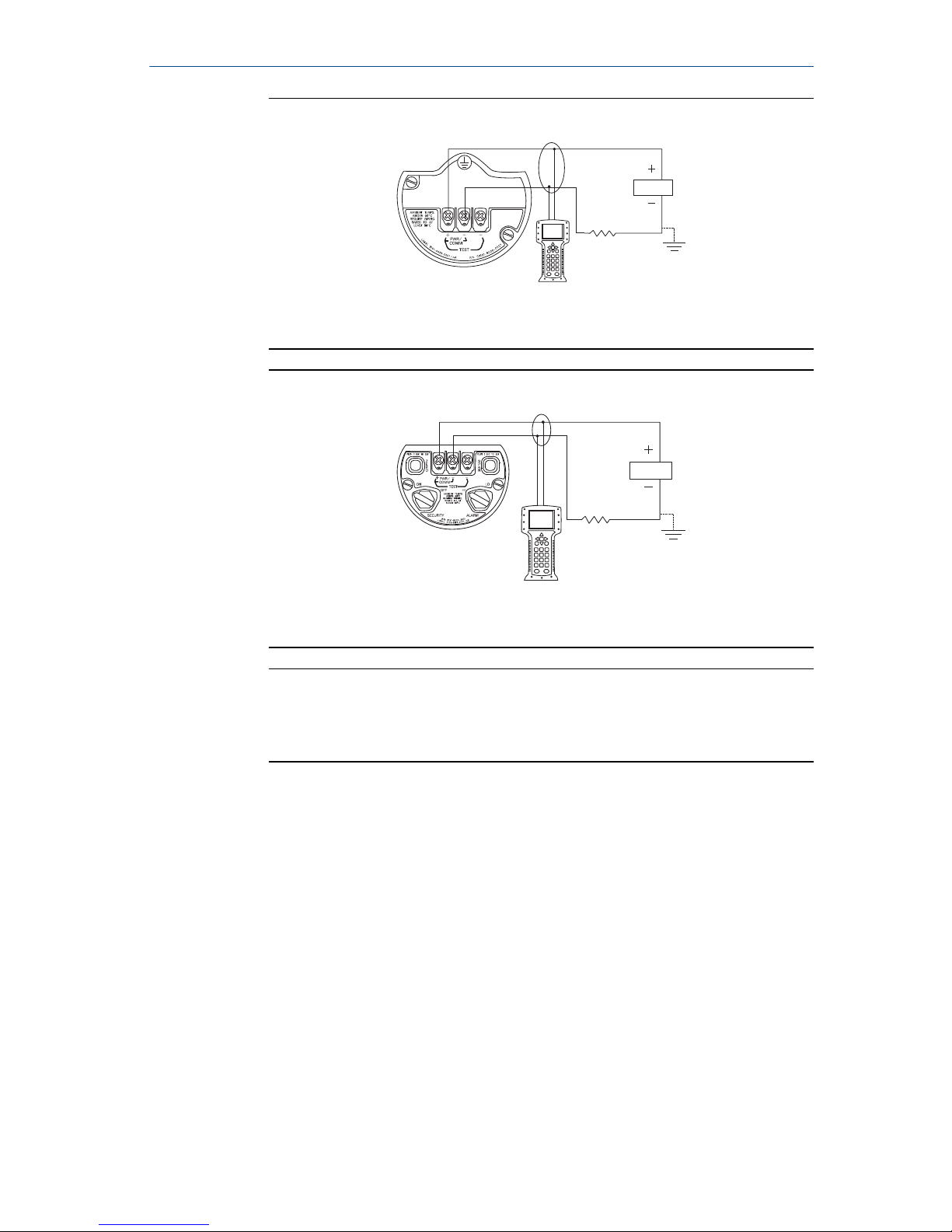
Figure 4-1: Transmitter Wiring (Plantweb Housing)
A
B
A. RL ≥ 250 Ω
B. Power supply
Figure 4-2: Transmitter Wiring (Junction Box Housing)
A
B
A. RL ≥ 250 Ω
B. Power supply
Note
Installation of the transient protection terminal block does not provide
transient protection unless the Rosemount 3051S case is properly
grounded.
4.1
Ground signal wiring
About this task
Do not run signal wiring in conduit or open trays with power wiring, or near
heavy electrical equipment. Grounding terminations are provided on the
sensor module and inside the terminal compartment. These grounds are used
when transient protection terminal blocks are installed or to fulfill local
regulations.
Procedure
1. Remove the Field Terminals housing cover.
2. Connect the wiring pair and ground as indicated in Figure 4-3.
The cable shield should:
December 2018 Quick Start Guide
Quick Start Guide 15

• Be trimmed close and insulated from touching the transmitter
housing
• Continuously connect to the termination point
• Be connected to a good earth ground at the power supply end
Figure 4-3: Wiring
DP
C
A
B
B
D
E
A. Insulate shield
B. Minimize distance
C. Connect shield back to the power supply ground
D. Trim shield and insulate
E. Safety ground
3. Replace the housing cover. It is recommended the cover be tightened
until there is no gap between the cover and the housing.
4. Plug and seal the unused conduit connection with the provided
conduit plug.
4.2
Remote display wiring and power up (if applicable)
The remote mount display and Interface system consists of a local transmitter
and a remote mount LCD display assembly. The local Rosemount 3051S
assembly includes a Junction Box housing with a three-position terminal block
integrally mounted to a sensor module. The remote mount LCD display
assembly consists of a dual compartment Plantweb housing with a seven
position terminal block. See Figure 4-4 for complete wiring instructions. The
following is a list of necessary information specific to the remote mount
display system:
• Each terminal block is unique for the remote display system.
• A 316 SST housing adaptor is permanently secured to the remote mount
LCD display Plantweb housing, providing an external ground and a means
for field mounting with the provided mounting bracket.
• A cable is required for wiring between the transmitter and remote mount
LCD display. The cable length is limited to 100 ft.
• 50 ft. (option M8) or 100 ft. (option M9) cable is provided for wiring
between the transmitter and remote mount LCD display. Option M7 does
not include cable; see recommended specifications below.
Quick Start Guide December 2018
16 Rosemount 3051S
 Loading...