

Page 1

00809-0100-4853, Rev BA
Rosemount™ 3051SMV MultiVariable
Transmitter
with FOUNDATION™ Fieldbus Protocol
Reference Manual
January 2019
™
Page 2

Safety messages
NOTICE
Read this manual before working with the product. For personal and system safety, and for optimum product performance make
sure you thoroughly understand the contents before installing, using, or maintaining this product.
For technical assistance, contacts are listed below:
Customer Central
Technical support, quoting, and order-related questions. United States - 1-800-999-9307
(7:00 am to 7:00 pm CST) Asia Pacific- 65 777 8211Europe/Middle East/Africa - 49 (8153) 9390
North American Response Center
Equipment service needs.
1-800-654-7768 (24 hours—includes Canada)
Outside of these areas, contact your local Emerson™ representative.
CAUTION
The products described in this document are NOT designed for nuclear-qualified applications. Using non-nuclear qualified
products in applications that require nuclear-qualified hardware or products may cause inaccurate readings.For information on
Rosemount nuclear-qualified products, contact your local Emerson Sales Representative.
WARNING
Explosions could result in death or serious injury.
Installation of this transmitter in an explosive environment must be in accordance with the appropriate local, national, and
international standards, codes, and practices. Review the approvals section of this manual for any restrictions associated with a
safe
• Before connecting a Field Communicator in an explosive atmosphere, ensure the instruments in the loop are installed in
accordance with intrinsically safe or non-incendive field wiring practices.
• In an explosion-proof/flameproof installation, do not remove the transmitter covers when power is applied to the unit.
Process leaks may cause harm or result in death.
• Install and tighten process connectors before applying pressure.
• Do not attempt to loosen or remove flange bolts while the transmitter is in service.
Electrical shock can result in death or serious injury.
• Avoid contact with the leads and terminals. High voltage that may be present on leads can cause electrical shock.
WARNING
• Before connecting a HART® communicator in an explosive atmosphere, ensure the instruments in the loop are installed in
accordance with intrinsically safe or non-incendive field wiring practices.
• In an Explosion-Proof/Flameproof installation, do not remove the transmitter covers when power is applied to the unit.
Process leaks may cause harm or result in death.
• Install and tighten process connectors before applying pressure.
2
Page 3

WARNING
Replacement equipment or spare parts not approved by Emerson for use as spare parts could reduce the pressure retaining
capabilities of the transmitter and may render the instrument dangerous.
• Use only bolts supplied or sold by Emerson as spare parts.
• Refer to page 208 for a complete list of spare parts.
Improper assembly of manifolds to traditional flange can damage sensor module.
• For safe assembly of manifold to traditional flange, bolts must break back plane of flange web (i.e., bolt hole) but must not
contact sensor module housing.
3
Page 4

4
Page 5

Reference Manual Contents
00809-0100-4853 January 2019
Contents
Chapter 1 Introduction.................................................................................................................. 7
1.1 Using this manual.............................................................................................................................7
1.2 Product overview..............................................................................................................................7
1.3 Product recycling/disposal................................................................................................................8
Chapter 2 Configuration................................................................................................................ 9
2.1 Section overview.............................................................................................................................. 9
2.2 Safety messages...............................................................................................................................9
2.3 Flow configuration......................................................................................................................... 10
2.4 Variable configuration....................................................................................................................17
2.5 Device configuration...................................................................................................................... 20
2.6 Device capabilities..........................................................................................................................22
Chapter 3 Installation...................................................................................................................25
3.1 Section overview............................................................................................................................ 25
3.2 Safety messages.............................................................................................................................25
3.3 Considerations............................................................................................................................... 26
3.4 Steps required for quick installation................................................................................................27
3.5 Rosemount 305 and 304 Manifolds................................................................................................ 45
Chapter 4 Operation and Maintenance.........................................................................................57
4.1 Section overview............................................................................................................................ 57
4.2 Safety messages.............................................................................................................................57
4.3 Calibration......................................................................................................................................58
4.4 Field upgrades and replacements................................................................................................... 63
Chapter 5 Troubleshooting.......................................................................................................... 71
5.1 Section overview............................................................................................................................ 71
5.2 Safety messages.............................................................................................................................71
5.3 Measurement troubleshooting.......................................................................................................72
5.4 Communication troubleshooting................................................................................................... 73
5.5 Service support...............................................................................................................................77
Appendix A Reference Data.............................................................................................................79
A.1 Product Certifications.....................................................................................................................79
A.2 Ordering Information, Specifications, and Dimensional Drawings.................................................. 79
Reference Manual 5
Page 6

Contents Reference Manual
January 2019 00809-0100-4853
6 Reference Manual
Page 7

Reference Manual Introduction
00809-0100-4853 January 2019
1 Introduction
1.1 Using this manual
The sections in this manual provide information on installing, operating, and maintaining
the Rosemount™ 3051S MultiVariable™ FOUNDATION™ Fieldbus Transmitter (3051SMV). The
sections are organized as follows:
• Configuration provides instruction on commissioning and operating the Rosemount
3051SMV and information on flow configuration and device configuration.
• Installation contains mechanical and electrical installation instructions.
• Operation and Maintenance contains operation and maintenance techniques.
• Troubleshooting provides troubleshooting techniques for the most common operating
problems.
• Reference Data supplies reference and specification data, as well as ordering
information and contains intrinsic safety approval information, European ATEX
directive information, and approval drawings.
1.2 Product overview
This manual covers the Rosemount 3051SMV FOUNDATION Fieldbus Transmitter. The device
measures differential pressure, static pressure, and process temperature and has the
capability to calculate mass flow.
The following transmitters are covered in this manual:
Table 1-1: Rosemount 3051SMV Fully Compensated Mass Flow (M) Transmitter
Measurement type Description
1 Differential pressure, static pressure, temperature
2 Differential pressure and static pressure
Table 1-2: Rosemount 3051SMV Process Variables Only (P) Transmitter
Measurement type Description
1 Differential pressure, static pressure, temperature
2 Differential pressure and static pressure
Table 1-3: Device Driver Information
Release
date
NAMUR
Device identification Device driver
NAMUR
hardware
revision
(1)
software
revision
(1)
FOUNDATION
Fieldbus
software
revision
identification
FOUNDATION
Fieldbus
universal
revision
Device
revision
(3)
Review
instructions
Manual
(2)
document
number
Review
functionality
Change
description
Reference Manual 7
Page 8

Measured
process
inputs
DP
P
T
A/D
Micro
FF communications output
Introduction
January 2019 00809-0100-4853
Reference Manual
Table 1-3: Device Driver Information (continued)
Release
date
May-16 1.0.xx 1.0.xx 1.0.2 6.1.2 1 00809-0100-4853None: Initial
(1) NAMUR Revision is located on the hardware tag of the device. Differences in level 3 changes,
signified above by xx, represent minor product changes as defined per NE53. Compatibility and
functionality are preserved and product can be used interchangeably.
(2) Foundation Fieldbus device revision can be read using a Foundation Fieldbus capable
configuration tool. Value shown is minimum revision that could correspond to NAMUR
Revisions.
(3) Device driver file names use device and DD revision. To access new functionality, the new Device
Driver must be downloaded. It is recommended to download new Device Driver files to ensure
full functionality.
Device identification Device driver
identification
Figure 1-1: Transmitter Data Flow
1.3 Product recycling/disposal
Recycling of equipment and packaging should be taken into consideration and disposed of
in accordance with local and national legislation/regulations.
Review
instructions
Review
functionality
Product Release
8 Reference Manual
Page 9

Reference Manual Configuration
00809-0100-4853 January 2019
2 Configuration
2.1 Section overview
This section contains information for the flow and device configuration of the Rosemount
3051S MultiVariable™ FOUNDATION™ Fieldbus Transmitter (3051SMV). Each FOUNDATION
Fieldbus host or configuration tool has different ways of displaying and performing
operations. Some hosts will use Device Descriptions (DD) and DD methods to complete
device configuration and will display data consistently across platforms.
The DD can be found on the FieldComm Group website at FieldCommGroup.org. There is
no requirement that a host or configuration tool support the features in the DD. For
DeltaV™ users, the DD can be found at EasyDeltaV.com. This section will describe how to
use the basic methods.
2.2 Safety messages
™
Instructions and procedures in this section may require special precautions to ensure the
safety of the personnel performing the operations. Information that raises potential safety
issues is indicated by a warning symbol ( ). Refer to the following safety messages before
performing an operation.
WARNING
Explosions could result in death or serious injury.
• Do not remove the transmitter cover in explosive atmospheres when the circuit is live.
• Before connecting a handheld communicator in an explosive atmosphere, make sure
the instruments in the loop are installed in accordance with intrinsically safe or nonincendive field wiring practices.
• Verify that the operating atmosphere of the transmitter is consistent with the
appropriate hazardous locations certifications.
• Both housing covers must be fully engaged to meet flameproof/explosion-proof
requirements.
Failure to follow these installation guidelines could result in death or serious injury.
• Make sure the device is installed by qualified personnel and in accordance with
applicable code of practice.
Electrical shock could cause death or serious injury.
• If the sensor is installed in a high-voltage environment and a fault or installation error
occurs, high voltage may be present on transmitter leads and terminals.
• Use extreme caution when making contact with the leads and terminals.
Reference Manual 9
Page 10

Configuration Reference Manual
January 2019 00809-0100-4853
2.3 Flow configuration
2.3.1 Engineering Assistant 5.5.1 ver. 2
Engineering Assistant 5.5.1 ver. 2 is PC-based software that performs flow configuration
for the Rosemount 3051SMV with the fully compensated mass flow feature board. It is
available as a standalone application or as an AMS SNAP-ON™, and is required to complete
the flow configuration for the Rosemount 3051SMV Transmitter.
The following are the minimum system requirements to install the Engineering Assistant
5.5.1 ver. 2 software:
• Intel® Core™ Duo, 2.4 GHz
• 600 MB of available hard disk space
• 2GB RAM
• Microsoft® Windows™ 7 Operating System (32 or 64 bit)
• FOUNDATION Fieldbus interface Learn more about the Emerson USB Fieldbus Interface
device and its configuration here: Emerson.com/AMS/USB-Fieldbus-Interface.
2.3.2
Installing Engineering Assistant 5.5.1 ver. 2 Stand-Alone
About this task
Note
If using full AMS™ Device Manager, do not uninstall it. Obtain the SNAP-ON version of EA or
install Engineering Assistant 5.5.1 ver. 2 Stand-Alone on another PC.
Procedure
1. Insert Rosemount Engineering Assistant (EA) Software disk into the DVD-ROM.
2. Right-click Setup.exe, select Run as Administrator.
3. Reboot the PC when prompted.
Note
After the reboot installation will continue. The disk should remain in the drive.
4. If there are old versions of EA 5, uninstall them by selecting Remove when
prompted. Once uninstalled, right-click Setup.exe, then select Run as
Administrator.
Note
Do NOT uninstall Engineering Assistant 6. Engineering Assistant 5 is not a
replacement for Engineering Assistant 6.
10 Reference Manual
Page 11

A
A
Reference Manual Configuration
00809-0100-4853 January 2019
2.3.3 Launching Engineering Assistant 5.5.1 ver. 2 and
connecting to the transmitter
About this task
Connect the FOUNDATION Fieldbus interface from the PC to the Rosemount 3051SMV
Fieldbus Transmitter.
Procedure
1. Open the transmitter cover on the side marked “Field Terminals”.
2. Connect the communication wires to the terminals labeled “Fieldbus Wiring”.
3. If the device is at a non-commissioned address, use the Emerson USB Fieldbus
Interface’s Configuration Utility to “Commission” the Device.
Note
The Emerson USB Fieldbus Interface can be configured to power the connected
Fieldbus device. Never attempt to use two power sources at the same time. Doing
so can disrupt communications and may compromise automation safety. Refer to
the Emerson USB Fieldbus Interface User Manual (AW7060MNL) for further
information.
4. Connect the Rosemount 3051SMV Transmitter to a computer (see Figure 2-1).
Figure 2-1: Connecting a PC to the Rosemount 3051SMV Using the USB Fieldbus
Interface
Rosemount 3051SMV without optional
process temperature connection
Rosemount 3051SMV with optional
process temperature connection
A. USB Fieldbus Interface
5. Launch the Rosemount 3051SMV Engineering Assistant for FOUNDATION Fieldbus
program by selecting MV Engineering Assistant from the Start menu.
OR
6. Launch AMS Device Manager if using the SNAP-ON Engineering Assistant.
Reference Manual 11
Page 12

Configuration Reference Manual
January 2019 00809-0100-4853
a) Right click the device to be configured.
b) Select SNAP-ON/Linked Apps > MV Engineering Assistant 5.5.1 ver. 2.
7. Start a new configuration or load a saved configuration from a file.
8. Perform the steps outlined in the Creating a flow configuration section.
9. Once the configuration is complete, disconnect MV Engineering Assistant and the
USB Fieldbus Interface. Then, attach the housing cover and tighten so that metal
contacts metal to meet flame-proof/explosion-proof requirements.
12 Reference Manual
Page 13
Reference Manual Configuration
00809-0100-4853 January 2019
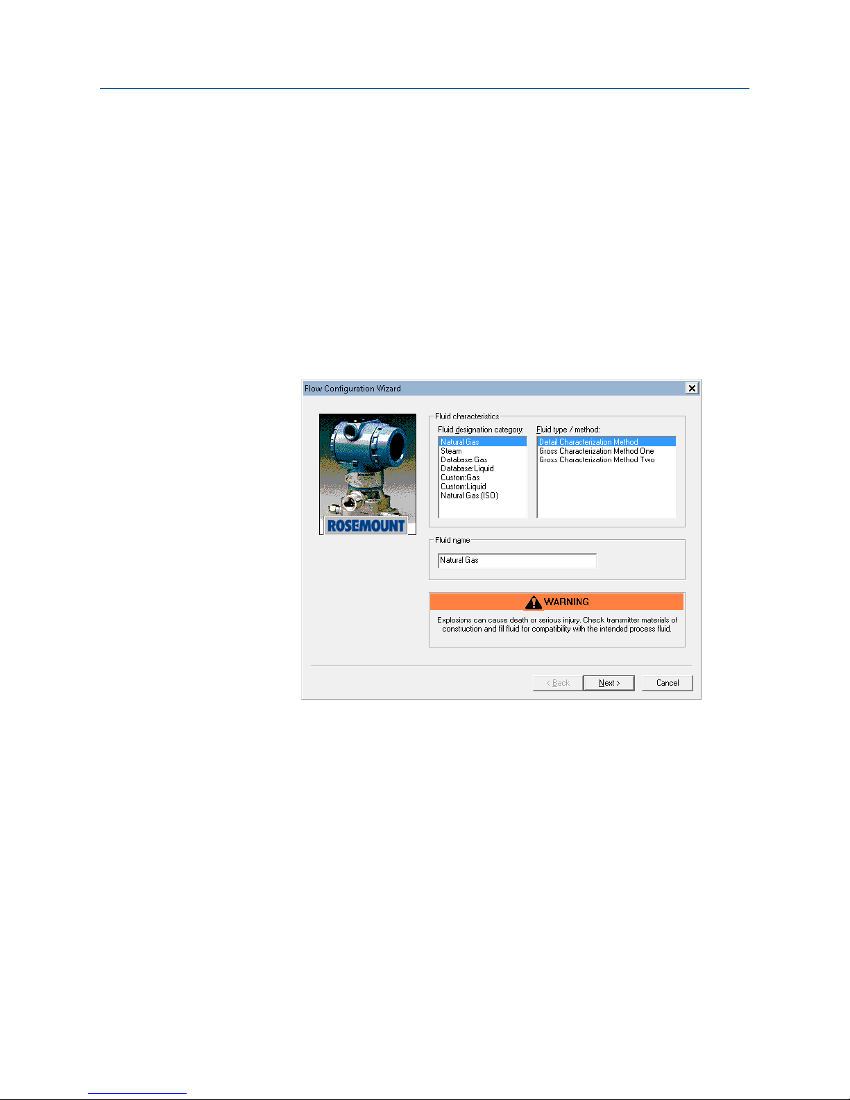
2.3.4 Creating a flow configuration
About this task
Engineering Assistant 5.5.1 ver. 2 is designed to guide the user through the setup of the
flow configuration for the Rosemount 3051SMV. This information will be used by the
Engineering Assistant to create the flow configuration parameters that can be sent to the
transmitter or saved for future use.
Procedure
1. Select the fluid designation category.
2. Select the fluid type.
3. Select Next.
Depending on the fluid selected, Engineering Assistant 5.5.1 ver. 2 may bring up a
screen for entering additional fluid information.
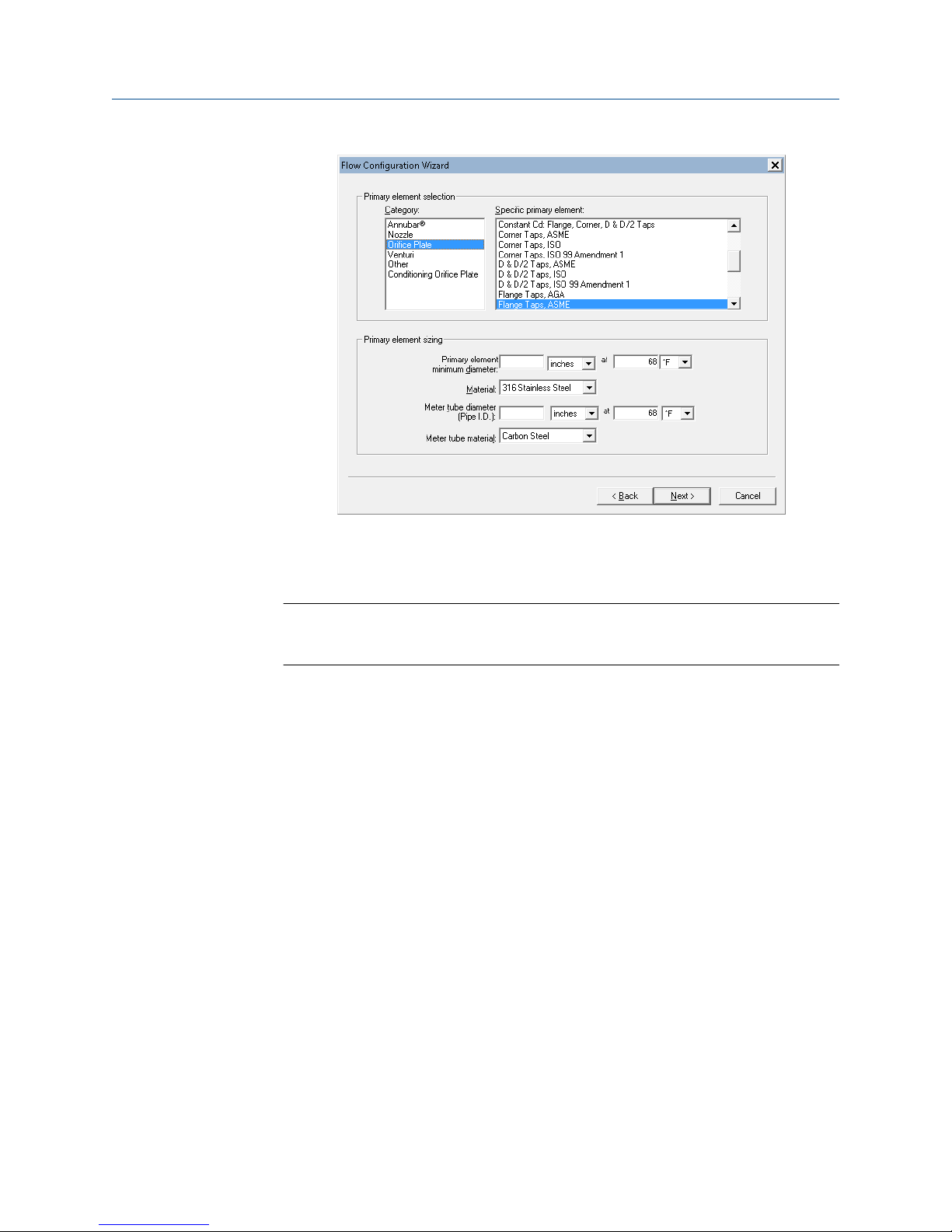
4. Select a primary element type, then enter the sizing information in the fields
provided.
5. Select Next.
Reference Manual 13
Page 14
Configuration Reference Manual
January 2019 00809-0100-4853
6. Enter the operating conditions for the fluid.
a) Select the pressure and temperature range based on the operating
conditions of the process, not the sensor range of the transmitter.
Note
An extremely large or small operating range may increase the uncertainty of the
flow calculation.
The units used for flow configuration are only used in the Engineering Assistant
software. For configuration of device variable units, see Units configuration.
7. Enter the atmospheric pressure.
The transmitter needs absolute pressure to calculate flow. If gage pressure is
measured, the transmitter will calculate absolute pressure based on the userdefined atmospheric pressure. Atmospheric pressure can be changed in the screen
below. This setting may also be configured per the atmospheric offset configuration
(see Static pressure on page 11) in the Sensor Transducer Block.
8. Select Next.
14 Reference Manual
Page 15

Reference Manual Configuration
00809-0100-4853 January 2019
9. Review fluid properties of the configuration.
10. Select Finish.
11. When prompted, save the flow configuration to the computer. The file must be
saved for review or to edit the mass flow configuration in the future.
Note
FOUNDATION Fieldbus mass flow configuration files cannot be uploaded from the
Rosemount 3051SMV. If the file is not saved, it cannot be retrieved.
Reference Manual 15
Page 16

Configuration Reference Manual
January 2019 00809-0100-4853
2.3.5 Sending a flow configuration to the transmitter
About this task
Select Send button to download the mass flow configuration file to the transmitter.
Sending the mass flow configuration file will overwrite the existing configuration in the
transmitter. Engineering Assistant will put the Mass Flow Transducer Block out of service
when sending the mass flow configuration.
Procedure
1. Select Send button. A confirmation message will display.
2. At the end of the download, choose which mode to put the Mass Flow Transducer
Block into, and then select Continue.
16 Reference Manual
Page 17

Reference Manual Configuration
00809-0100-4853 January 2019
2.3.6 Mass flow test calculation
The mass flow test calculation method allows the user to verify the flow configuration of
the Rosemount 3051SMV by entering expected values for the differential pressure,
absolute pressure, and process temperature variables. Test calculation units are always in
inH2O at 68 °F for differential pressure, psi for static pressure and °F for temperature.
To perform a test calculation, select Actions > Methods > Methods > Mass Flow Test
Calculation and follow the on-screen prompts.
Note
The device must be in Automatic Mode in order to successfully perform a mass flow test
calculation. If the resource block is not in automatic mode, the test calculation method
will still run, but the method will report the last live values, rather than the test calculation
outputs.
2.4 Variable configuration
2.4.1 Units configuration
Units for transmitter variables are configured in the XD Scale parameter in each AI Block.
Each AI Block is connected to a transmitter variable according to the Channel parameter in
the AI Block. When the units in an AI Block are changed, the units of the connected
channel variable will be changed in the Sensor Transducer Block or the Mass Flow
Transducer Block accordingly. If multiple AI Blocks are set to the same channel, the XD
Scale units must be manually synchronized to resolve configuration errors.
2.4.2
Mass flow
The following configuration items are found in the Mass Flow Transducer Block.
Note
These configuration items only apply to the Fully Compensated Mass Flow transmitter.
Reference Manual 17
Page 18

Configuration Reference Manual
January 2019 00809-0100-4853
Low flow cutoff
If the measured Differential Pressure value is less than the Low Flow Cutoff value, the
transmitter will calculate the Flow Rate value as zero.
The unit for this value is always inH2O at 68 °F.
Process temperature mode
The mass flow calculation can use a live process temperature reading or a fixed value
based on the selected Process Temperature Mode. To configure it, select Actions >
Methods > Methods > Mass Flow PT Mode Setup and follow the on-screen prompts.
Mode Description
Normal The transmitter will only use the actual measured process temperature value. If the
temperature sensor fails, the Flow output will go to Bad status.
Backup The transmitter will use the actual measured Process Temperature value. If the
temperature sensor fails, the transmitter will use the value shown in Fixed PT.
Fixed The transmitter will always use the temperature value shown in Fixed PT.
2.4.3
2.4.4
Note
The unit for the Fixed Process Temperature value always matches the Process
Temperature primary value unit. To change this unit setting, see Units configuration.
Differential pressure
The following configuration items are found in the Sensor Transducer Block.
Damping
The damping setting changes the response time of the transmitter; higher values can
smooth variations in output readings caused by rapid input changes. Determine the
appropriate damping setting based on the necessary response time, signal stability, and
other requirements.
The setting for Differential Pressure Damping also affects the Mass Flow.
Static pressure
The following configuration items are found in the Sensor Transducer Block.
Damping
The damping setting changes the response time of the transmitter; higher values can
smooth variations in output readings caused by rapid input changes. Determine the
appropriate damping setting based on the necessary response time, signal stability, and
other requirements.
The setting for static pressure damping affects both absolute and gage pressure
measurements.
18 Reference Manual
Page 19

Reference Manual Configuration
00809-0100-4853 January 2019
Atmospheric offset
Both absolute and gage pressure are available as variables. The type of transmitter ordered
will determine which variable is measured. The transmitter will calculate either absolute or
gage pressure based on the user-defined atmospheric offset.
2.4.5 Process temperature
The following configuration items are found in the Sensor Transducer Block.
Damping
The damping setting changes the response time of the transmitter; higher values can
smooth variations in output readings caused by rapid input changes. Determine the
appropriate damping setting based on the necessary response time, signal stability, and
other requirements.
Callendar-Van Dusen Coefficients
The Rosemount 3051SMV accepts Callendar-Van Dusen constants from a calibrated RTD
schedule and generates a special custom curve to match that specific sensor Resistance
vs. Temperature performance. Matching the specific sensor curve with the transmitter
configuration enhances the temperature measurement accuracy. Under Actions > Methods
> Methods, the Callendar-Van Dusen constants R0, A, B, and C can be viewed. If the
Callendar-Van Dusen constants are known for the user’s specific Pt 100 RTD sensor, the
constants R0, A, B, and C may be edited by selecting the Callendar-Van Dusen Setup
method and following the on-screen prompts. The user may also view the α, β, and δ
coefficients by selecting the View Alpha, Beta, Delta button. The constants R0, α, β, and δ
may be edited by selecting the Callendar-Van Dusen Setup and following the on-screen
prompts. To reset the transmitter to the IEC 751 Defaults, select the Reset to IEC 751
Defaults method.
User-defined process temperature sensor limits
Process temperature sensor limits can be changed to allow early detection of RTD failures.
When the limits are exceeded, the transmitter will display a Process Temperature Out of
Limits alert in the transmitter status, set the PT measurement status to uncertain, and will
stop using the measured temperature value in the flow calculation. See Mass flow on page
10 for more information on configuring the process temperature mode for mass flow.
Enable/disable process temperature
Using the PT Measurement parameter, the Process Temperature measurement can be
disabled to prevent undesired diagnostic alarms and local display screens. This feature
may be useful if the Process Temperature option was ordered but will not be used or if the
RTD in use has failed and a replacement is not readily available.
When the Process Temperature measurement is disabled, the Process Temperature
measurement status will be “bad”. If using mass flow calculations, set the Mass Flow’s
Process Temperature Mode to Fixed to allow calculations to continue. Once an RTD is
available and wired, set the PT Measurement to Enabled and the Process Temperature
Mode to Normal to allow the live reading to be used for mass flow calculations.
Reference Manual 19
Page 20

Configuration Reference Manual
January 2019 00809-0100-4853
2.4.6 Variable simulation
The following configuration items are found in the AI Block.
Simulate replaces the channel value coming from the Sensor Transducer Block. For testing
purposes, it is possible to manually drive the output of the Analog Input Block to a desired
value. There are two ways to do this.
Manual mode
Complete the steps below to change only the OUT_VALUE and not the OUT_STATUS of
the AI Block.
Procedure
1. Set the block mode to Manual.
2. Change the Output Value to the desired value.
3. Restore the original block mode when finished.
Simulate
Procedure
1. If the simulate switch on the electronics board is in the Disabled position, move it to
the Enabled position. See Set the switches for more information.
2. Set the Simulate En/Disable parameter to Active.
3. Enter the desired Simulate Value and Status. Make sure the block mode is Auto to
see the value propagate through the block.
4. Set the Simulate En/Disable parameter back to Disabled when finished simulating.
2.5 Device configuration
2.5.1 Display configuration
The following configuration items are found in the LCD display Transducer Block.
The transmitter features a three-line display. The first line of five characters displays the
output description, the second line of seven digits displays the actual value, and the third
line of six characters displays engineering units. The LCD display meter can also display
diagnostic messages.
Each parameter configured for display will appear on the LCD display for a brief period
before the next parameter is displayed. Up to four different variables may be shown on the
display.
The LCD display meter is preconfigured to show the measured variables that correspond
to the transmitter configuration. It can be configured to display any measured or
calculated value that has a status parameter with it (i.e. FOUNDATION Fieldbus DS-65
parameter type). Configure each parameter for display as stated below.
20 Reference Manual
Page 21

Reference Manual Configuration
00809-0100-4853 January 2019
Display parameter select
The display of each configured parameter can be turned on or off by editing the Display
Parameter Select parameter.
Block type
Enter the Block Type for the block that contains the parameter to be displayed.
Block tag
Enter the Block Tag of the block that contains the parameter to be displayed.
Parameter index
Enter the Block Index of the parameter to be displayed.
Custom tag
Enter up to five characters to be displayed on the top line of the LCD display when this
parameter is displayed.
2.5.2
Units type
Select auto when the parameter to be displayed is pressure, temperature, mass flow, or
percent. The units of the parameter will be read and automatically displayed on the LCD
display.
Select custom to display up to six characters as configured in the Custom Units parameter.
Select none if the parameter is to be displayed without associated units.
Custom units
If the Units Type is set to custom specify up to six characters here to be displayed with the
configured parameter.
Write lock
The following configuration items are found in the Resource Block.
The Rosemount 3051SMV Transmitter supports both hardware and software write lock.
Locking the transmitter will prevent configuration changes until it is unlocked again.
Software write lock
To configure software write lock, select Actions > Methods > Methods > Write Lock
Setup and follow the on-screen prompts for Software Write Lock. The security switch on
the electronics board must be in the unlocked position to use software write lock.
To unlock the transmitter, run the Write Lock Setup method again and follow the onscreen prompts.
Reference Manual 21
Page 22

Configuration Reference Manual
January 2019 00809-0100-4853
Hardware write lock
To configure Hardware Write Lock, select Actions > Methods > Methods > Write Lock
Setup and follow the on-screen prompts for Hardware Write Lock. This method must be
run twice if software write lock is already configured, first to unlock the device, then to
switch to hardware write lock.
To lock or unlock the transmitter, set the security switch on the electronics board as
shown in Figure 3-9. Note that the hardware security switch is only followed if the
transmitter has been configured to use hardware write lock as described above.
The state of the security switch can be read in the Device Switches State parameter.
2.6 Device capabilities
2.6.1 General block information
Reference information on the process control function blocks can be found in the Function
Block Reference Manual.
2.6.2
2.6.3
Link active scheduler
The Rosemount 3051SMV can be designated to act as the backup Link Active Scheduler
(LAS) in the event that the LAS is disconnected from the segment. As the backup LAS, the
Rosemount 3051SMV will take over the management of communications until the host is
restored. The host system may provide a configuration tool specifically designed to
designate a particular device as a backup LAS.
Capabilities
There are a total of 20 Virtual Communication Relationships (VCRs). Two are permanent
and 18 are fully configurable by the host system. Twenty-five link objects are available.
Table 2-1: Network Parameters
Network parameter Value
Slot Time 6
Maximum Response Delay 4
Maximum Inactivity to Claim LAS Delay 5
Minimum Inter DLPDU Delay 7
Time Sync class 4 (1ms)
Maximum Scheduling Overhead 10
Per CLPDU PhL Overhead 4
Maximum Inter-channel Signal Skew 0
Required Number of Post-transmission-gap-ext Units 0
Required Number of Preamble-extension Units 1
22 Reference Manual
Page 23

Reference Manual Configuration
00809-0100-4853 January 2019
Host timer recommendations
T1 = 96000 T2 = 9600000 T3 = 480000
Table 2-2: Block Execution Times
Block Time (in ms)
Analog Input 20
PID 25
Arithmetic 20
Input Selection 20
Signal Characterizer 20
Integrator 20
Output Splitter 20
Control Selector 20
2.6.4 Node address
The transmitter is shipped at a temporary (248+) address. This enables FOUNDATION
Fieldbus host systems to automatically recognize the device and move it to a permanent
address.
2.6.5
Block instantiation
The Rosemount 3051SMV supports the use of function block instantiation. When a device
supports block instantiation, the number of blocks and block types can be defined to
match specific application needs. The number of blocks that can be instantiated is only
limited by the amount of memory within the device and the block types that are
supported by the device. Instantiation does not apply to standard device blocks like the
Resource or Transducer Blocks. Block instantiation is done by the host control system or
configuration tool, but not all hosts are required to implement this functionality. Refer to
the specific host or configuration tool manual for more information.
Reference Manual 23
Page 24

Configuration Reference Manual
January 2019 00809-0100-4853
24 Reference Manual
Page 25

Reference Manual Installation
00809-0100-4853 January 2019
3 Installation
3.1 Section overview
The information in this section covers installation considerations for the Rosemount
3051S MultiVariable™ FOUNDATION™ Fieldbus Transmitter (3051SMV). A Quick Start Guide is
shipped with every transmitter to describe basic installation, wiring, and startup
procedures. Dimensional drawings for each transmitter variation and mounting
configuration are included in Rosemount 3051SMV Product Data Sheet.
3.2 Safety messages
Procedures and instructions in this section may require special precautions to ensure the
safety of the personnel performing the operation. Information that raises potential safety
issues is indicated with a warning symbol ( ). Refer to the following safety messages
before performing an operation preceded by this symbol.
™
Reference Manual 25
Page 26

Installation
January 2019 00809-0100-4853
Reference Manual
WARNING
Explosions could result in death or serious injury.
• Do not remove the transmitter cover in explosive atmospheres when the circuit is live.
• Fully engage both transmitter covers to meet explosion-proof requirements.
• Before connecting a communicator in an explosive atmosphere, make sure the
instruments in the segment are installed in accordance with intrinsically safe or nonincendive field wiring practices.
• Verify the operating atmosphere of the transmitter is consistent with the appropriate
hazardous locations certifications.
Electrical shock could cause death or serious injury.
• Avoid contact with the leads and terminals.
Process leaks could result in death or serious injury.
• Install and tighten all four flange bolts before applying pressure.
• Do not attempt to loosen or remove flange bolts while the transmitter is in service.
Use only bolts supplied or sold by Emerson as spare parts.
• Replacement equipment or spare parts not approved by Emerson™ for use as spare
parts could reduce the pressure retaining capabilities of the transmitter and may
render the instrument dangerous.
Improper assembly of manifolds to traditional flange can damage sensor module.
• For safe assembly of manifold to traditional flange, bolts must break back plane of
flange web (i.e., bolt hole) but must not contact sensor module housing.
Sensor module and electronics housing must have equivalent approval labeling in order to
maintain hazardous location approvals.
• When upgrading, verify sensor module and electronics housing certifications are
equivalent. Differences in temperature class ratings may exist, in which case the
complete assembly takes the lowest of the individual component temperature classes
(for example, a T4/T5 rated electronics housing assembled to a T4 rated sensor module
is a T4 rated transmitter.)
3.3 Considerations
3.3.1 General
Measurement performance depends upon proper installation of the transmitter and
impulse piping. Mount the transmitter close to the process and use minimum piping to
achieve best performance. Also, consider the need for easy access, personnel safety,
practical field calibration, and a suitable transmitter environment. Install the transmitter
to minimize vibration, shock, and temperature fluctuation.
Important
Install the enclosed pipe conduit plug (found in the box) in the unused conduit plug
opening. For straight threads, a minimum of seven threads must be engaged. For tapered
threads, a minimum of five threads must be engaged; install the plug wrench-tight. For
material compatibility considerations, see the Material Selection Technical Note.
26 Reference Manual
Page 27

Reference Manual
00809-0100-4853 January 2019
Installation
3.3.2 Mechanical
Steam service
For steam service or for applications with process temperatures greater than the limits of
the transmitter, do not blow down impulse piping through the transmitter. Flush lines
with the blocking valves closed and refill lines with water before resuming measurement.
Side mounting
When the transmitter is mounted on its side, position the coplanarflange to ensure proper
venting or draining. Mount the flange as shown in Mount the transmitter, keeping drain/
vent connections on the bottom for gas service and on the top for liquid service.
3.3.3
Environmental
Best practice is to mount the transmitter in an environment that has minimal ambient
temperature change. The transmitter electronics temperature operating limits are –40 to
185 °F (–40 to 85 °C). Rosemount 3051S Product Data Sheet lists the sensing element
operating limits. Mount the transmitter so it is not susceptible to vibration and mechanical
shock and does not have external contact with corrosive materials.
3.4 Steps required for quick installation
• Start >
• Mount the transmitter
• Commissioning (paper) tag
• Set the switches
• Wire, ground, and power
• > Finish
3.4.1
Mount the transmitter
Figure 3-1 illustrates a typical Rosemount 3051SMV installation site measuring dry gas
with an orifice plate.
Reference Manual 27
Page 28

Flow
A
B
C
D
Installation Reference Manual
January 2019 00809-0100-4853
Figure 3-1: Typical Rosemount 3051SMV Installation Site
A. Rosemount 3051SMV
B. RTD cable
C. Pt 100 RTD sensor
D. Process connections
Mounting brackets
The Rosemount 3051SMV can be mounted to a 2-in. (50.88 mm) pipe or to a panel using
an optional mounting bracket. The B4 Bracket (SST [Stainless steel]) option is for use with
the coplanar flange process connection. shows bracket dimensions and mounting
configurations for the B4 option. Other bracket options are listed in Table 3-1. When
installing the transmitter to one of the optional mounting brackets, torque the bolts to
125 in-lb (0,9 N-m).
Table 3-1: Mounting Brackets
Options Description Mounting type Bracket material Bolt material
B4 Coplanar flange
bracket
B1 Traditional flange
bracket
2-in. pipe/panel SST SST
2-in. pipe Painted CS (Carbon
steel)
CS
28 Reference Manual
Page 29

Reference Manual
00809-0100-4853 January 2019
Installation
Table 3-1: Mounting Brackets (continued)
Options Description Mounting type Bracket material Bolt material
B2 Traditional flange
bracket
B3 Traditional flange flat
bracket
B7 Traditional flange
bracket
B8 Traditional flange
bracket
B9 Traditional flange flat
bracket
BA Traditional flange
bracket
BC Traditional flange flat
bracket
Panel Painted CS CS
2-in. pipe Painted CS CS
2-in. pipe Painted CS SST
Panel Painted CS SST
2-in. pipe Painted CS SST
2-in. pipe SST SST
2-in. pipe SST SST
Flange bolts
The Rosemount 3051SMV can be shipped with a coplanar flange or a traditional flange
installed with four 1.75-in (44.4 mm). flange bolts. Mounting bolts and bolting
configurations for the coplanar and traditional flanges can be found in Cover installation.
SST bolts supplied by Emerson are coated with a lubricant to ease installation. CS bolts do
not require lubrication. No additional lubricant should be applied when installing either
type of bolt. Bolts supplied by Emerson are identified by their head markings:
A. Carbon Steel (CS) Head Markings
B. Stainless Steel (SST) Head Markings
C. Alloy K-500 Head Marking
Note
The last digit in the F593_ head marking may be any letter between A and M.
Reference Manual 29
Page 30

Installation
January 2019 00809-0100-4853
Reference Manual
Bolt installation
Only use bolts supplied with the 2051 or provided by Emerson Automation Solutions as
spare parts. When installing the transmitter to one of the optional mounting brackets,
torque the bolts to 125 in-lb. (0,9 N-m). Use the following bolt installation procedure:
Procedure
1. Finger-tighten the bolts.
2. Torque the bolts to the initial torque value using a crossing pattern.
3. Torque the bolts to the final torque value using the same crossing pattern.
Example
Torque values for the flange and manifold adapter bolts are as follows:
Table 3-2: Bolt Installation Torque Values
Bolt material Initial torque value Final torque value
CS-ASTM-A449 Standard 300 in.-lb (34 N-m) 650 in.-lb (73 N-m)
316 SST—Option L4 150 in.-lb (17 N-m) 300 in.-lb (34 N-m)
ASTM-A-193-B7M—Option L5 300 in.-lb (34 N-m) 650 in.-lb (73 N-m)
ASTM-A-193 Class 2, Grade B8M—Option L8 150 in.-lb (17 N-m) 300 in.-lb (34 N-m)
Figure 3-2: Traditional Flange Bolt Configurations
A. Drain/vent
B. Plug
Dimensions are in inches (millimeters).
30 Reference Manual
Page 31

Reference Manual
00809-0100-4853 January 2019
Installation
Figure 3-3: Mounting Bolts and Bolt Configurations for Coplanar Flange
Dimensions are in inches (millimeters).
Description Size in inches (mm)
Flange Bolts 1.75 (44)
Flange/Adapter Bolts 2.88 (73)
Manifold/Flange Bolts 2.25 (57)
Note
Rosemount 2051T transmitters are direct mount and do not require bolts for
process connection.
Mounting requirements
Impulse piping configurations depend on specific measurement conditions. Refer to
Figure 3-4 for examples of the following mounting configurations:
Liquid flow measurement
• Place taps to the side of the line to prevent sediment deposits on the process isolators.
• Mount the transmitter beside or below the taps so gases vent into the process line.
• Mount drain/vent valve upward to allow gases to vent.
Gas flow measurement
• Place taps in the top or side of the line.
• Mount the transmitter beside or above the taps so to drain liquid into the process line.
Steam flow measurement
• Place taps to the side of the line.
• Mount the transmitter below the taps to ensure that impulse piping will remain filled
with condensate.
• In steam service above 250 °F (121 °C), fill impulse lines with water to prevent steam
from contacting the transmitter directly and to ensure accurate measurement start-up.
Reference Manual 31
Page 32

FLOW
Installation
January 2019 00809-0100-4853
Reference Manual
Note
For steam or other elevated temperature services, it is important that temperatures at the
transmitter process connection do not exceed the transmitter’s operating limits.
Figure 3-4: Installation Examples
Liquid service Gas service Steam service
3.4.2 O-rings
The two styles of Rosemount flange adapters (Rosemount 1151 and Rosemount
3051/2051/2024/3095) each require a unique O-ring (see Figure 3-5). Use only the O-ring
designed for the corresponding flange adapter.
WARNING
Failure to install proper flange adapter O-rings may cause process leaks, which can result in
death or serious injury. The two flange adapters are distinguished by unique O-ring
grooves. Only use the O-ring that is designed for its specific flange adapter, as shown
below. When compressed, PTFE O-rings tend to cold flow, which aids in their sealing
capabilities.
32 Reference Manual
Page 33

Reference Manual
00809-0100-4853 January 2019
Installation
Figure 3-5: O-rings
A. Flange adapter
B. O-ring
C. PFTE based
D. Elastomer
Note
You should replace PTFE O-rings if you remove the flange adapter.
Reference Manual 33
Page 34

Commissioning Tag
DEVICE ID:
001151AB00010001440-121698091 725
DEVICE REVISION: 1.0
PHYSICAL DEVICE TAG
DEVICE ID:
001151AB00010001440-121698091 725
DEVICE REVISION: 1.0
S / N :
PHYSICAL DEVICE TAG
Device Barcode
Installation
January 2019 00809-0100-4853
Reference Manual
3.4.3 Commissioning (paper) tag
To identify which device is at a particular location use the removable tag provided with the
transmitter. Ensure the physical device tag (PD tag field) is properly entered in both places
on the removable commissioning tag and tear off the bottom portion for each
transmitter.
Figure 3-6: Commissioning Tag
3.4.4 Rotate housing
34 Reference Manual
To improve field access to wiring or to better view the optional LCD display:
Procedure
1. Loosen the housing rotation set screw.
2. Rotate the housing clockwise to the desired location. If the desired location cannot
be achieved due to thread limit, rotate the housing counter clockwise to the desired
location (up to 360° from thread limit).
CAUTION
Do not rotate the housing more than 180° without first performing a disassembly
procedure. Over-rotation may sever the electrical connection between the sensor
module and the feature board electronics.
3. Retighten the housing rotation set screw up to 30 in-lb.
4. For wireless, consider access to the power module when selecting housing rotation.
Page 35

A
A
Reference Manual
00809-0100-4853 January 2019
Figure 3-7: Transmitter Housing Set Screw (Plantweb)
A. Housing rotation set screw (3/32-in.)
Figure 3-8: Transmitter Housing Set Screw (Junction Box)
Installation
A. Housing rotation set screw (3/32-in.)
3.4.5
Reference Manual 35
LCD display rotation
In addition to housing rotation, the optional LCD display can be rotated in 90° increments
by squeezing the two tabs, pulling out, rotating and snapping back into place.
Note
If LCD display pins are inadvertently removed from the feature board, re-insert the pins
before snapping the LCD display back into place.
Page 36

Installation
January 2019 00809-0100-4853
Reference Manual
3.4.6 Set the switches
About this task
Set Simulate and Security switch position before installation (location of switches shown in
Figure 3-9), as desired.
• The Simulate switch enables or disables the ability to set simulated alerts or simulated
measured value and status.
• The Security switch allows (unlocked symbol) or prevents (locked symbol) any
configuration of the transmitter.
Further security settings are available in the software, including settings which use a
software lock. Additionally, these settings can be used to disable both hardware and
software locks.
Use the following procedure to change the switch configuration:
Procedure
1. If the transmitter is installed, secure the segment, and remove power.
2. Remove the housing cover opposite the field terminal side. Do not remove the
instrument cover in explosive atmospheres when the circuit is live.
3. Slide the security and simulate switches into the preferred position.
4. Reinstall the housing cover and tighten so the cover is fully seated with metal to
metal contact between the housing and cover in order to meet explosion proof
requirements.
5. If the transmitter was installed, reapply power.
36 Reference Manual
Page 37

SECURITY
SIMULATE
ENABLE
DISABLE
C
D
E
F
B
A
Reference Manual
00809-0100-4853 January 2019
Installation
Example
Figure 3-9: Simulate and Security Switches
A. Security unlocked position
B. Security switch
C. Security locked position
D. Simulate disabled position
E. Simulate switch
F. Simulate enabled position
3.4.7
Wire, ground, and power
Use a copper wire of sufficient size to ensure the voltage across the transmitter power
terminals does not drop below 9 Vdc. Power supply voltage can be variable, especially
under abnormal conditions such as when operating on battery backup. A minimum of 12
Vdc under normal operating conditions is recommended. Shielded twisted pair Type A
cable is recommended.
Note
The power terminals are polarity insensitive, which means the electrical polarity of the
power leads does not matter when connecting to the power terminals. If polarity sensitive
devices are connected to the segment, terminal polarity should be followed.
3.4.8
Signal wiring and shield grounding
Do not run signal wiring in conduit or open trays with power wiring, or near heavy
electrical equipment. Grounding terminations are provided on the outside of the
electronics housing and inside the terminal compartment. These grounds are used when
transient protection terminal blocks are installed or to fulfill local regulations.
Reference Manual 37
Page 38

Installation
January 2019 00809-0100-4853
Reference Manual
Procedure
1. Remove the field terminals housing cover.
2. To power the transmitter, connect the power leads to the terminals indicated on
the terminal block label.
3. Tighten the terminal screws to ensure adequate contact.
4. Trim the cable shield as short as practical and insulate from touching the
transmitter housing as indicated in Figure 1 and Figure 2.
Note
Do NOT ground the cable shield at the transmitter; if the cable shield touches the
transmitter housing, it can create ground loops and interfere with communications.
To protect the fieldbus segment from noise, grounding techniques for shield wire
require a single grounding point for shield wire to avoid creating a ground loop.
a) Ensure the cable shield maintains a continuous connection to the power
supply ground.
b) Connect the cable shields for the entire segment to a single good earth
ground at the power supply.
Note
Improper grounding is the most frequent cause of poor segment
communications.
5. Reinstall the housing cover and tighten so the cover is fully seated with metal to
metal contact between the housing and cover in order to meet explosion proof
requirements.
6. Plug and seal unused conduit connections.
NOTICE
When the enclosed threaded plug is utilized in the conduit opening, it must be
installed with a minimum thread engagement in order to comply with explosionproof requirements. For straight threads, a minimum of seven threads must be
engaged. For tapered threads, a minimum of five threads must be engaged.
38 Reference Manual
Page 39

Reference Manual
00809-0100-4853 January 2019
Installation
3.4.9 Power supply
The transmitter requires between 9 and 32 Vdc (9 and 30 Vdc for intrinsic safety, and 9
and 17.5 Vdc for FISCO intrinsic safety) to operate and provide complete functionality.
3.4.10 Power conditioner
A Fieldbus segment requires a power conditioner to isolate the power supply, filter, and
decouple the segment from other segments attached to the same power supply.
3.4.11 Grounding
Signal wiring of the fieldbus segment can not be grounded. Grounding one of the signal
wires will shut down the entire fieldbus segment.
Transmitter case grounding
Always ground the transmitter case in accordance with national and local electrical codes.
The most effective transmitter case grounding method is a direct connection to earth
ground with minimal impedance. Methods for grounding the transmitter case are listed
below.
Internal ground connection
The internal ground connection screw is inside the FIELD TERMINALS side of the
electronics housing. This screw is identified by a ground symbol (
connection screw is standard on all Rosemount 3051SMV Transmitters.
). The ground
Reference Manual 39
Page 40

A
Installation
January 2019 00809-0100-4853
Reference Manual
A. Ground lug
External ground connection
The external ground connection is located on the exterior of the transmitter housing. This
connection is only available with option D4 and T1.
40 Reference Manual
Page 41

A
B
Reference Manual
00809-0100-4853 January 2019
Installation
A. External ground lug
B. External ground assembly (03151-9060-0001)
Note
Grounding the transmitter case via threaded conduit connection may not provide
sufficient ground continuity.
Transient protection terminal block grounding
The transmitter can withstand electrical transients of the energy level usually encountered
in static discharges or induced switching transients. However, high-energy transients,
such as those induced in wiring from nearby lightning strikes, can damage the transmitter.
The transient protection terminal block can be ordered as an installed option (option code
T1) or as a spare part to retrofit existing Rosemount 3051SMV Transmitters in the field.
The lightning bolt symbol shown in Figure 3-10 identifies the transient protection terminal
block.
Reference Manual 41
Page 42

A
A
Installation
January 2019 00809-0100-4853
Figure 3-10: Transient Protection Terminal Block with RTD
Reference Manual
A. Lightning bolt symbol location
Figure 3-11: Transient Protection Terminal Block without RTD
A. Lightning bolt symbol location
42 Reference Manual
Page 43

Reference Manual
00809-0100-4853 January 2019
Note
The transient protection terminal block does not provide transient protection unless the
transmitter case is properly grounded. Use the guidelines to ground the transmitter case
(see Grounding).
Installation
3.4.12 Signal termination
A terminator should be installed at the beginning and end of every fieldbus segment.
3.4.13 Install optional process temperature input (Pt 100 RTD
Sensor)
About this task
Note
To meet ATEX/IECEx Flameproof certification, only ATEX/IECEx Flameproof cables
(temperature input code C30, C32, C33, or C34) may be used.
Procedure
1. Mount the Pt 100 RTD Sensor in the appropriate location.
Use shielded four-wire cable for the process temperature connection.
2. Connect the RTD cable to the Rosemount 3051S MultiVariable Transmitter by
inserting the cable wires through the unused housing conduit and connect to the
four screws on the transmitter terminal block. An appropriate cable gland should be
used to seal the conduit opening around the cable.
3. Connect the RTD cable shield wire to the ground lug in the housing.
Reference Manual 43
Page 44

C
B
Red
Red
White
White
A
Installation
Reference Manual
January 2019 00809-0100-4853
Figure 3-12: Transmitter RTD Wiring Connection
A. Ground lug
B. RTD cable assembly wires
C. Pt 100 RTD sensor
Three-wire RTD
A four-wire Pt 100 RTD is required to maintain published performance specifications. A
three-wire Pt 100 RTD may be used with degraded performance. If connecting to a threewire RTD, use a four-wire cable to connect the Rosemount 3051SMV terminal block to the
RTD connection head. Within the RTD connection head, connect two of the same colored
wires from the Rosemount 3051SMV to the single colored wire of the RTD sensor.
44 Reference Manual
Page 45

Reference Manual Installation
00809-0100-4853 January 2019
3.5 Rosemount 305 and 304 Manifolds
The Rosemount 305 Integral Manifold is available in two designs: coplanar and traditional.
The traditional Rosemount 305 can be mounted to most primary elements with mounting
adapters.
Rosemount 305 Integral Coplanar Rosemount 305 Integral Traditional
The Rosemount 304 comes in two basic styles: traditional (flange X flange and flange X
pipe) and wafer. The Rosemount 304 Traditional Manifold comes in 2-, 3-, and 5-valve
configurations. The Rosemount 304 Wafer Manifold comes in 3- and 5-valve
configurations.
Rosemount 304 Traditional
Rosemount 304 Wafer
Reference Manual 45
Page 46

Installation
January 2019 00809-0100-4853
Reference Manual
3.5.1 Install Rosemount™ 305 Integral Manifold
Procedure
1. Inspect the PTFE sensor module O-rings.
You may reuse undamaged O-rings. If the O-rings are damaged (if they have nicks
or cuts, for example), replace with O-rings designed for Rosemount transmitters.
Important
If replacing the O-rings, take care not to scratch or deface the O-ring grooves or the
surface of the isolating diaphragm while you remove the damaged O-rings.
2. Install the Integral Manifold on the sensor module. Use the four 2.25-in (57.2 mm).
manifold bolts for alignment. Finger tighten the bolts; then tighten the bolts
incrementally in a cross pattern as seen in Figure 3-13 to final torque value.
See Flange bolts for complete bolt installation information and torque values. When
fully tightened, the bolts should extend through the top of the sensor
module housing.
Figure 3-13: Bolt Tightening Pattern
3. If you have replaced the PTFE sensor module O-rings, re-tighten the flange bolts
after installation to compensate for cold flow of the O-rings.
3.5.2
46 Reference Manual
Install Rosemount 304 Conventional Manifold
About this task
See Safety messages for complete warning information.
Procedure
1. Align the Conventional Manifold with the transmitter flange. Use the four manifold
bolts for alignment.
2. Finger tighten the bolts; then tighten the bolts incrementally in a cross pattern to
final torque value.
See Flange bolts for complete bolt installation information and torque values.When
fully tightened, the bolts should extend through the top of the sensor module
housing.
Page 47

Reference Manual
00809-0100-4853 January 2019
3. Leak-check assembly to maximum pressure range of transmitter.
Installation
3.5.3 Manifold operation
WARNING
Improper installation or operation of manifolds may result in process leaks, which may
cause death or serious injury.
Always perform a zero trim on the transmitter/manifold assembly after installation to
eliminate any shift due to mounting effects. See Sensor trim overview.
Coplanar transmitters
Operate three and five-valve manifolds
Performing zero trim at static line pressure
About this task
In normal operation, the two isolate (block) valves between the process ports and the
transmitter will be open, and the equalize valve will be closed.
A. Drain/vent valve
B. Isolate (open)
C. Equalize (closed)
D. Process
E. Isolate (open)
F. Drain/vent valve
Procedure
1. To zero trim the transmitter, close the isolate valve on the low side (downstream)
side of the transmitter.
Reference Manual 47
Page 48

Installation
January 2019 00809-0100-4853
Reference Manual
A. Drain/vent valve
B. Isolate (open)
C. Equalize (closed)
D. Process
E. Isolate (closed)
F. Drain/vent valve
2. Open the equalize valve to equalize the pressure on both sides of the transmitter.
The manifold is now in the proper configuration for performing a zero trim on the
transmitter.
A. Drain/vent valve
B. Isolate (open)
C. Equalize (open)
D. Process
E. Isolate (closed)
F. Drain/vent valve
3. After zeroing the transmitter, close the equalize valve.
A. Drain/vent valve
B. Isolate (open)
C. Equalize (closed)
D. Process
E. Isolate (closed)
F. Drain/vent valve
48 Reference Manual
Page 49

Reference Manual
00809-0100-4853 January 2019
Installation
4. Finally, to return the transmitter to service, open the low side isolate valve.
A. Drain/vent valve
B. Isolate (open)
C. Equalize (closed)
D. Process
E. Isolate (open)
F. Drain/vent valve
Operate five-valve natural gas manifold
Performing zero trim at static line pressure
About this task
Five-valve natural gas configurations shown:
In normal operation, the two isolate (block) valves between the process ports and the
transmitter will be open, and the equalize valves will be closed. Vent valves may be open
or closed.
A. (Plugged)
B. Isolate (open)
C. Process
D. Equalize (closed)
E. Equalize (closed)
F. Drain vent (closed)
G. Process
H. Isolate (open)
I. (Plugged)
Procedure
1. To zero trim the transmitter, first close the isolate valve on the low pressure
(downstream) side of the transmitter and the vent valve.
Reference Manual 49
Page 50

Installation
January 2019 00809-0100-4853
Reference Manual
A. (Plugged)
B. Isolate (open)
C. Process
D. Equalize (closed)
E. Equalize (closed)
F. Drain vent (closed)
G. Process
H. Isolate (closed)
I. (Plugged)
2. Open the equalize valve on the high pressure (upstream) side of the transmitter.
A. (Plugged)
B. Isolate (open)
C. Process
D. Equalize (open)
E. Equalize (closed)
F. Drain vent (closed)
G. Process
H. Isolate (closed)
I. (Plugged)
3. Open the equalize valve on the low pressure (downstream) side of the transmitter.
The manifold is now in the proper configuration for zeroing the transmitter.
50 Reference Manual
Page 51

Reference Manual
00809-0100-4853 January 2019
Installation
A. (Plugged)
B. Isolate (open)
C. Process
D. Equalize (open)
E. Equalize (open)
F. Drain vent (closed)
G. Process
H. Isolate (closed)
I. (Plugged)
4. After zeroing the transmitter, close the equalize valve on the low pressure
(downstream) side of the transmitter.
A. (Plugged)
B. Isolate (open)
C. Process
D. Equalize (open)
E. Equalize (closed)
F. Drain vent (closed)
G. Process
H. Isolate (closed)
I. (Plugged)
5. Close the equalize valve on the high pressure (upstream) side.
Reference Manual 51
Page 52

Installation
January 2019 00809-0100-4853
A. (Plugged)
B. Isolate (open)
C. Process
D. Equalize (closed)
E. Equalize (closed)
F. Drain vent (closed)
G. Process
H. Isolate (closed)
I. (Plugged)
6. Finally, to return the transmitter to service, open the low side isolate valve and vent
valve.
The vent valve can remain open or closed during operation.
Reference Manual
A. (Plugged)
B. Isolate (open)
C. Process
D. Equalize (closed)
E. Equalize (closed)
F. Drain vent (closed)
G. Process
H. Isolate (open)
I. (Plugged)
In-line transmitters
2-valve and block and bleed style manifolds
Isolating the transmitter
About this task
In normal operation, the isolate (block) valve between the process port and transmitter
will be open and the test/vent valve will be closed. On a block and bleed style manifold, a
single block valve provides transmitter isolation, and a bleed screw provides drain/vent
capabilities.
52 Reference Manual
Page 53

Reference Manual
00809-0100-4853 January 2019
Installation
A. Transmitter
B. Vent (closed)
C. Isolate
D. Process (open)
Procedure
1. To isolate the transmitter, close the isolate valve.
A. Transmitter
B. Vent (closed)
C. Isolate
D. Process (closed)
2. To bring the transmitter to atmospheric pressure, open the vent valve or bleed
screw.
A. Transmitter
B. Vent (open)
C. Isolate
D. Process (closed)
Note
A ¼-in (6.35 mm). male NPT pipe plug may be installed in the test/vent port; you
will need to remove it with a wrench in order to vent the manifold properly.
Always use caution when venting directly to atmosphere.
Reference Manual 53
Page 54

Installation
January 2019 00809-0100-4853
3. After venting to atmosphere, perform any required calibration and then close the
test/vent valve or replace the bleed screw.
A. Transmitter
B. Vent (closed)
C. Isolate
D. Process (closed)
4. Open the isolate (block) valve to return the transmitter to service.
Reference Manual
A. Transmitter
B. Vent (closed)
C. Isolate
D. Process (open)
Adjust valve packing
Over time, the packing material inside a Rosemount manifold may require adjustment in
order to continue to provide proper pressure retention. Not all Rosemount manifolds have
this adjustment capability. The Rosemount manifold model number will indicate what
type of stem seal or packing material has been used.
About this task
The following steps are provided as a procedure to adjust valve packing:
Procedure
1. Remove all pressure from device.
2. Loosen manifold valve jam nut.
3. Tighten manifold valve packing adjuster nut ¼ turn.
4. Tighten manifold valve jam nut.
5. Re-apply pressure and check for leaks.
54 Reference Manual
Page 55

A
D
C
B
E
F
G
Reference Manual
00809-0100-4853 January 2019
Postrequisites
Repeat the above steps if necessary. If the above procedure does not result in proper
pressure retention, replace the complete manifold.
Figure 3-14: Valve Components
Installation
A. Bonnet
B. Stern
C. Packing
D. Ball seat
E. Packing adjuster
F. Jam nut
G. Packing follower
Reference Manual 55
Page 56

Installation Reference Manual
January 2019 00809-0100-4853
56 Reference Manual
Page 57

Reference Manual Operation and Maintenance
00809-0100-4853 January 2019
4 Operation and Maintenance
4.1 Section overview
This section contains information on operating and maintaining the Rosemount™ 3051S
MultiVariable™ FOUNDATION™ Fieldbus Transmitter (3051SMV). Each Foundation Fieldbus
host or configuration tool has different ways of displaying and performing operations.
Some hosts will use Device Descriptions (DD) and DD Methods to complete device
configuration and will display data consistently across platforms. The DD can be found on
the FieldComm Group website at FieldCommGroup.org. There is no requirement that a
host or configuration tool support the features in the DD. For DeltaV™ users, the DD can
be found at EasyDeltaV.com. The information in this section will describe how to use the
basic methods.
Based on the configuration ordered, some measurements (e.g. process temperature)
and/or calculation types (e.g. fully compensated mass flow, process variables only) may
not be available. Available measurements and/or calculation types are determined by the
multivariable type and measurement type codes ordered. See Rosemount 3051S Product
Data Sheet for more information.
4.2 Safety messages
Procedures and instructions in this section may require special precautions to ensure the
safety of the personnel performing the operation. Information that raises potential safety
issues is indicated with a warning symbol ( ). Refer to the following safety messages
before performing an operation preceded by this symbol.
Reference Manual 57
Page 58

Operation and Maintenance Reference Manual
January 2019 00809-0100-4853
WARNING
Failure to follow these installation guidelines could result in death or serious injury.
• Ensure only qualified personnel perform the installation.
Explosions could result in death or serious injury.
• Do not remove the transmitter cover in explosive atmospheres when the circuit is live.
• Before connecting a communicator in an explosive atmosphere, make sure the
instruments in the segment are installed in accordance with intrinsically safe or nonincendive field wiring practices.
• Both housing covers must be fully engaged to meet flameproof/explosion-proof
requirements.
• Verify that the operating atmosphere of the transmitter is consistent with the
appropriate hazardous locations certifications.
Electrical shock could cause death or serious injury.
• If the sensor is installed in a high-voltage environment and a fault or installation error
occurs, high voltage may be present on transmitter leads and terminals.
• Use extreme caution when making contact with the leads and terminals.
Process leaks could result in death or serious injury.
• Install and tighten all four flange bolts before applying pressure.
• Do not attempt to loosen or remove flange bolts while the transmitter is in service.
Replacement equipment or spare parts not approved by Emerson™ for use as spare parts
could reduce the pressure retaining capabilities of the transmitter and may render the
instrument dangerous.
• Use only bolts supplied or sold by Emerson as spare parts.
Improper assembly of manifolds to traditional flange can damage the device.
• For safe assembly of manifold to traditional flange, bolts must break back plane of
flange web (i.e., bolt hole) but must not contact the sensor module.
Static electricity can damage sensitive components.
• Observe safe handling precautions for static-sensitive components.
4.3 Calibration
4.3.1 Calibration overview
Before calibrating the sensor complete configuration of the device in Configuration.
Calibration of the Rosemount 3051SMV involves the following tasks.
• Sensor trim
• Zero or lower sensor trim
58 Reference Manual
Page 59

Reference Manual Operation and Maintenance
00809-0100-4853 January 2019
4.3.2 Sensor trim overview
Trim the sensors using either upper or lower sensor or zero trim functions. Trim functions
vary in complexity and are application-dependent.
Note
When performing a sensor trim on a pressure sensor, it is possible to degrade the
performance of the sensor if inaccurate calibration equipment is used. Use calibration
equipment that is at least three times as accurate as the pressure sensor of the Rosemount
3051SMV Transmitter.
4.3.3 Determining necessary sensor trims
Bench calibration is not recommended for new instruments. The transmitter can be set
back to factory settings using the Restore Factory Calibration.
About this task
For transmitters that are field installed, the manifolds discussed in Manifold operation
allow the differential transmitter to be zeroed using the zero trim function. Both 3-valve
and 5-valve manifolds are discussed. This field calibration will eliminate any pressure
offsets caused by mounting effects and static pressure effects of the process. Determine
the necessary trims with the following steps.
4.3.4
Procedure
1. Complete a zero trim.
2. Apply pressure.
3. Check the pressure, if the pressure does not match the applied pressure, perform a
sensor trim (see Full trim).
Types of pressure trim
Zero trim
Zero trim is a single-point offset adjustment. It is useful for compensating for mounting
position effects and is most effective when performed with the transmitter installed in its
final mounting position. When performing a zero trim with a manifold, refer to Rosemount
305 and 304 Manifolds.
Note
To perform a zero trim function, the measured value of transmitter can be no larger than
five percent of the upper sensor limit from zero. The transmitter will not allow the user to
perform a zero trim on an absolute static pressure sensor. To correct mounting position
effects on the absolute static pressure sensor, perform a sensor trim. The lower sensor
trim function provides an offset correction similar to the zero trim function, but it does not
require zero-based input.
Reference Manual 59
Page 60

Operation and Maintenance Reference Manual
January 2019 00809-0100-4853
Full trim
Full sensor trim is a two-point sensor calibration where two end-point pressures are
applied, and all output is linearized between them. Always adjust the lower sensor trim
value first to establish the correct offset. Adjustment of the upper sensor trim value
provides a slope correction to the characterization curve based on the lower sensor trim
value. The trim values allow the user to optimize performance over a specified measuring
range at the calibration temperature.
4.3.5 Restore factory calibration
The factory calibration recall feature will restore the transmitter to the original factory
calibration. This feature can be useful for recovering from an inadvertent zero trim or
inaccurate pressure source. When this feature is used, the transmitter’s upper and lower
trim values are set to the values configured at the factory. If custom trim values were
specified when the transmitter was ordered, the device will recall those values. If custom
trim values were not specified, the device will recall the default upper and lower sensor
limits.
4.3.6
Differential pressure sensor calibration
Navigate to the differential pressure calibration to complete a zero trim procedure or a full
DP sensor trim. Differential pressure sensor calibration units can be set in the Sensor
Transducer Block.
Zero trim
To perform a DP sensor zero trim, select Actions > Methods > Methods > Zero
Differential Pressure Trim and follow the on-screen prompts. To perform a zero trim
function, the measured value of transmitter can be no larger than five percent of the
upper sensor limit from zero.
Note
When performing a DP sensor zero trim, ensure that the equalizing valve is open and all
wet legs are filled to the correct levels.
Upper and lower sensor trim
Note
When performing a sensor trim on a pressure sensor, it is possible to degrade the
performance of the sensor if inaccurate calibration equipment is used. Use calibration
equipment that is at least three times as accurate as the pressure sensor of the Rosemount
3051SMV Transmitter.
A reference pressure device is required to perform a full sensor trim. Allow the pressure
input to stabilize for ten seconds before entering any values. To perform a DP full trim,
select Actions > Methods > Methods > Lower Differential Pressure Trim, follow the onscreen prompts, and then select Actions > Methods > Methods > Upper Differential
Pressure Trim and follow the on-screen prompts.
60 Reference Manual
Page 61

Reference Manual Operation and Maintenance
00809-0100-4853 January 2019
Note
The transmitter allows approximately five percent URL deviation from the characterized
curve established at the factory.
4.3.7 Static pressure sensor calibration
The static pressure calibration allows the user to complete either a zero trim procedure or
a full SP sensor trim. Static pressure sensor calibration units can be set in the Sensor
Transducer Block.
Zero trim and lower sensor trim
A zero trim can be performed on a gage sensor and a lower sensor trim can be performed
on an absolute sensor to correct for mounting position effects. To perform a zero trim on a
gage static pressure sensor, select Actions > Methods > Methods > Zero Static Pressure
Trim and follow the on-screen prompts.
To correct for mounting position effects on transmitters equipped with an absolute static
pressure sensor, perform a lower sensor trim. This is accomplished by selecting Actions >
Methods > Methods > Lower Static Pressure Trim and follow the on-screen prompts.
The lower sensor trim function provides an offset correction similar to the zero trim
function, but it does not require a zero-based input.
Upper and lower sensor trim
Note
When performing a sensor trim on a pressure sensor, it is possible to degrade the
performance of the sensor if inaccurate calibration equipment is used. Use calibration
equipment that is at least three times as accurate as the pressure sensor of the Rosemount
3051SMV Transmitter.
A reference pressure device is required to perform a full sensor trim. Allow the pressure
input to stabilize for ten seconds before entering any values. To perform a SP full trim
select Actions > Methods > Methods > Lower Static Pressure Trim and follow the onscreen prompts then select Actions > Methods > Methods > Upper Static Pressure Trim
and follow the on-screen prompts.
Reference Manual 61
Page 62

Operation and Maintenance Reference Manual
January 2019 00809-0100-4853
4.3.8 Process temperature sensor calibration
The Temperature Calibration allows the user to perform a sensor trim of a process
temperature sensor. Process temperature sensor calibration units can be set in the Sensor
Transducer Block.
Process temperature trim
To calibrate the Process Temperature Input using the sensor trim, use the following
procedure.
About this task
Note
When performing a sensor trim on a sensor, it is possible to degrade the performance of
the sensor if inaccurate calibration equipment is used. Use calibration equipment that is at
least three times as accurate as the sensor of the Rosemount 3051SMV Transmitter.
Procedure
1. Set up a Temperature Calibrator to simulate a Pt 100 (100-ohm platinum, alpha 385
RTD) per manufacture recommendations. See Install optional process temperature
input (Pt 100 RTD Sensor) for wiring information.
2. Select Actions > Methods > Methods > Trim Process Temperature and select the
type of calibration. Adjust the calibrator/RTD simulator to a test point temperature
value that represents a minimum process temperature (for example, 32 °F or 0 °C) if
completing a lower sensor trim. Adjust the calibrator/RTD simulator to a test point
temperature value that represents the maximum process temperature (for
example, 140 °F or 60 °C) if completing an upper sensor trim.
62 Reference Manual
Page 63

Reference Manual Operation and Maintenance
00809-0100-4853 January 2019
4.4 Field upgrades and replacements
4.4.1 Disassembly considerations
CAUTION
During disassembly, do not remove the instrument cover in explosive atmospheres when
the circuit is live as this may result in serious injury or death. Also, be aware of the
following:
• Follow all plant safety rules and procedures.
• Isolate and vent the process from the transmitter before removing the transmitter
from service.
• Disconnect optional process temperature sensor leads and cable.
• Remove all other electrical leads and conduit.
• Detach the process flange by removing the four flange bolts and two alignment screws
that secure it.
• Do not scratch, puncture, or depress the isolating diaphragms.
• Clean isolating diaphragms with a soft rag and a mild cleaning solution, then rinse with
clear water.
• Whenever the process flange or flange adapters are removed, visually inspect the PTFE
O-rings. Emerson recommends reusing O-rings if possible. If the O-rings show any signs
of damage, such as nicks or cuts, they should be replaced.
4.4.2
Housing assembly including electronics board
Field device labels
The sensor module label reflects the replacement model code for reordering a complete
transmitter. Replacement model codes are also viewable in the host by selecting
Overview > Device Information > Identification.
Replacing housing assembly including electronics board
Removing the electronics board
During disassembly, do not remove the instrument cover in explosive atmospheres when
the circuit is live as this may result in serious injury or death.
About this task
The Rosemount 3051SMV Transmitter electronics board is located opposite the field
terminal side in the housing. To remove the electronics board, perform the following
procedure:
Procedure
1. Remove the housing cover opposite the field terminal side.
2. Remove the LCD display, if applicable. Hold in the two clips and pull outward. This
will provide better access to the two screws located on the electronics board.
Reference Manual 63
Page 64

A
B
Operation and Maintenance Reference Manual
January 2019 00809-0100-4853
3. Loosen the two captive screws located on the electronics board.
4. Pull out the electronics board to expose and locate the sensor module connector,
(Figure 4-1).
5. Press the locking tabs and pull the sensor module connector upwards (avoid pulling
wires). Housing rotation may be required to access locking tabs. See Rotate housing
for more information.
Example
Figure 4-1: Sensor Module Connector View
A. Electronics board
B. Sensor module connector
Separate the sensor module assembly from the housing
To prevent damage to the sensor module connector, remove the electronics board from
the sensor module assembly and remove the connector before separating the sensor
module assembly from the housing.
Procedure
1. Loosen the housing rotation set screw by one full turn with a 3/32-in (2.38 mm). hex
wrench (see Figure 4-2).
2. Unscrew the housing from the sensor module threads.
64 Reference Manual
Page 65

A
A
Reference Manual Operation and Maintenance
00809-0100-4853 January 2019
Example
Figure 4-2: Set Screw
A. Housing rotation set screw (3/32-in.)
Attach the sensor module assembly to the housing
Procedure
1. Apply a light coat of low temperature silicon grease to the sensor module threads
and O-ring.
2. Install the V-Seal (03151-9061-0001) at the bottom of the housing (Figure 4-3).
3. Thread the housing completely onto the sensor module assembly. The housing
must be no more than one full turn from flush with the sensor module assembly to
comply with flame-proof/explosion-proof requirements.
4. Tighten the housing rotation set screw using a 3/32-in (2.38 mm). hex wrench to a
recommended torque of 30 in-lbs (3.4 N-m).
Figure 4-3: V-Seal
A. Black rubber V-seal
Reference Manual 65
Page 66

Operation and Maintenance Reference Manual
January 2019 00809-0100-4853
Install electronics board in the housing
Procedure
1. Apply a light coat of low temperature silicon grease to the sensor module connector
O-ring.
2. Insert the sensor module connector into the top of the sensor module assembly.
Ensure the locking tabs are fully engaged.
3. Gently slide the electronics board into the housing, making sure the pins from the
housing properly engage the receptacles on the electronics board.
4. Tighten the captive screws. If using an LCD display, see LCD display.
5. Attach the housing cover and tighten so that metal contacts metal to meet flame-
proof/explosion-proof requirements.
4.4.3
Terminal block
About this task
Electrical connections are located on the terminal block in the compartment labeled
“FIELD TERMINALS.” The terminal block may be replaced or upgraded to add transient
protection. If the device has a transient terminal block, the terminal block must be
replaced with another transient terminal block. When installing a transient terminal block
refer to grounding procedures in Installation. Part numbers can be found in Spare parts
list. Loosen the two captive screws (Figure 4-4), and pull the entire terminal block out.
Note
The terminal block does not identify FISCO.
Figure 4-4: Terminal Blocks
Without optional process temperature
connections
With optional process temperature connections
66 Reference Manual
Page 67

B
C
A
Reference Manual Operation and Maintenance
00809-0100-4853 January 2019
Procedure
1. Gently slide the terminal block into the housing, making sure the pins from the
Rosemount 3051SMV housing properly engage the receptacles on the terminal
block.
2. Tighten the captive screws on the terminal block.
3. Attach the Rosemount 3051SMV housing cover and tighten so metal contacts
metal to meet flame-proof/explosion-proof requirements.
4.4.4 LCD display
Transmitters ordered with the LCD display will be shipped with the display installed.
Installing the display on an existing transmitter requires the LCD display kit (part number
00753-9004-0001 for aluminum housing and 00753-9004-0004 for stainless steel
housing).
About this task
Use the following procedure and Figure 4-5 to install the LCD display:
Procedure
1. If the transmitter is installed on a segment, then secure the segment and
disconnect power.
2. Remove the transmitter cover on the electronics board side (opposite the field
terminals side). Do not remove instrument covers in explosive environments when
circuit is live.
3. Engage the four-pin connector into the electronics board and snap LCD display into
place.
4. To meet explosion-proof requirements, reinstall the housing cover and tighten so
the cover is fully seated with metal to metal contact between the housing and
cover.
Example
Figure 4-5: Optional LCD Display
A. Electronics board
B. LCD display
C. Display cover
Reference Manual 67
Page 68

A
Operation and Maintenance Reference Manual
January 2019 00809-0100-4853
4.4.5 Flange and drain vent
The Rosemount 3051SMV Transmitter is attached to the process connection flange by
four bolts and two alignment cap screws.
Procedure
1. Remove the two alignment cap screws.
Figure 4-6: Alignment Cap Screws
A. Alignment cap screw
2. Remove the four bolts and separate the transmitter from the process connection,
but leave the process connection flange in place and ready for re-installation.
Note
If installation uses a manifold, see Manifold operation.
3. Inspect the sensor module PTFE O-rings. If the O-rings are undamaged, they may be
reused. Emerson recommends reusing O-rings if possible. If the O-rings show any
signs of damage, such as nicks or cuts, they should be replaced (part number
03151-9042-0001 for glass-filled PTFE and part number 03151-9042-0002 for
graphite-filled PTFE).
Note
If replacing the O-rings, be careful not to scratch or deface the O-ring grooves or the
surface of the isolating diaphragm when removing the damaged O-rings.
4. Install the process flange on the sensor module process connection. To hold the
process flange in place, install the two alignment cap screws finger tight (these
screws are not pressure retaining). Do not overtighten; this will affect module-toflange alignment.
5. Install the appropriate flange bolts.
a) If the installation requires a ½–18 NPT connection(s), use four 1.75-in (44.4
mm). flange bolts. Finger tighten the bolts. Go to Step d.
b) If the installation requires a ½–14 NPT connection(s), use flange adapters
and four 2.88-in (73.2 mm). process flange/adapter bolts.
c) Hold the flange adapters and adapter O-rings in place while finger-tightening
the bolts.
68 Reference Manual
Page 69

Reference Manual Operation and Maintenance
00809-0100-4853 January 2019
d) Tighten the bolts to the initial torque value using a crossed pattern. See Table
4-1 for appropriate torque values.
e) Tighten the bolts to the final torque value using a crossed pattern. See Table
4-1 for appropriate torque values. When fully tightened, the bolts should
extend through the top of the module housing.
f) Torque alignment screws to 30 in-lbs. (3.4 N-m). If the installation uses a
conventional manifold, then install flange adapters on the process end of the
manifold using the 1.75-in (44.4 mm). flange bolts supplied with the
transmitter.
Table 4-1: Bolt Installation Torque Values
Bolt material Initial torque value Final torque value
CS-ASTM-A449 Standard 300 in-lb (34 N-m) 650 in-lb (73 N-m)
316 SST—Option L4 150 in-lb (17 N-m) 300 in-lb (34 N-m)
ASTM-A-193-B7M—Option L5 300 in-lb (34 N-m) 650 in-lb (73 N-m)
Alloy K-500—Option L6 300 in-lb (34 N-m) 650 in-lb (73 N-m)
ASTM-A-453-660—Option L7 150 in-lb (17 N-m) 300 in-lb (34 N-m)
ASTM-A-193-B8M—Option L8 150 in-lb (17 N-m) 300 in-lb (34 N-m)
6. If the sensor module PTFE O-rings are replaced, re-torque the flange bolts and
alignment cap screws after installation to compensate for seating of the PTFE Oring.
7. Install the drain/vent valve.
a) Apply sealing tape to the threads on the seat. Starting at the base of the valve
with the threaded end pointing toward the installer, apply two clockwise
turns of sealing tape.
b) Take care to place the opening on the valve so that process fluid will drain
toward the ground and away from human contact when the valve is opened.
c) Tighten the drain/vent valve to 250 in-lb (28.25 N-m).
d) Tighten the stem to 70 in-lb (8 N-m).
Note
Due to the Range 1 DP Sensor's high accuracy at low pressures, extra steps are
required to optimize performance. It is necessary to temperature soak the assembly
using the following procedure.
8. After replacing O-rings on DP Range 1 transmitters and re-installing the process
flange, expose the transmitter to a temperature of 185 °F (85 °C) for two hours.
9. Re-tighten the flange bolts in a cross pattern.
10. Again, expose the transmitter to a temperature of 185 °F (85 °C) for two hours
before calibration.
Reference Manual 69
Page 70

Operation and Maintenance Reference Manual
January 2019 00809-0100-4853
70 Reference Manual
Page 71

Reference Manual Troubleshooting
00809-0100-4853 January 2019
5 Troubleshooting
5.1 Section overview
This section provides summarized troubleshooting suggestions for the most common
operating problems on the Rosemount™ 3051S MultiVariable™ FOUNDATION™ Fieldbus
Transmitter (3051SMV).
If a malfunction is suspected despite the absence of any diagnostic messages on the
communicator display, follow the procedures described to verify transmitter hardware
and process connections are in good working order. Always deal with the most likely and
easiest-to-check conditions first.
5.2 Safety messages
Procedures and instructions in this section may require special precautions to ensure the
safety of the personnel performing the operations. Information that raises potential safety
issues is indicated by a warning symbol ( ). Refer to the following safety messages before
performing an operation preceded by this symbol.
WARNING
Explosions could result in death or serious injury.
• Do not remove the transmitter cover in explosive atmospheres when the circuit is live.
• Before connecting a communicator in an explosive atmosphere, make sure the
instruments in the segment are installed in accordance with intrinsically safe or nonincendive field wiring practices.
• Verify that the operating atmosphere of the transmitter is consistent with the
appropriate hazardous locations certifications.
• Both housing covers must be fully engaged to meet flameproof/explosion-proof
requirements.
Failure to follow these installation guidelines could result in death or serious injury.
• Ensure only qualified personnel perform the installation.
Electrical shock could cause death or serious injury.
• If the sensor is installed in a high-voltage environment and a fault or installation error
occurs, high voltage may be present on transmitter leads and terminals.
• Use extreme caution when making contact with the leads and terminals.
Static electricity can damage sensitive components.
• Observe safe handling precautions for static-sensitive components.
Reference Manual 71
Page 72

Troubleshooting Reference Manual
January 2019 00809-0100-4853
5.3 Measurement troubleshooting
The transmitter provides a means to display the current process variables and flow
calculations. If the process variable reading is unexpected, this section provides the
symptoms and possible corrective actions.
Table 5-1: Unexpected Process Variable (PV) Readings
Symptom Corrective action
High PV
Reading,
Erratic PV
Reading, Low
or no PV
reading
Primary element
• Check for restrictions at the primary element.
• Check the installation and condition of the primary element.
• Note any changes in process fluid properties that may affect output.
Impulse piping
• Check to ensure the pressure connection is correct.
• Check for leaks or blockage.
• Check to ensure that blocking valves are fully open.
• Check for entrapped gas in liquid lines or for liquid in gas lines.
• Check to ensure the density of fluid in impulse lines is unchanged.
• Check for sediment in the transmitter process flange.
• Make sure that process fluid has not frozen within the process flange.
Power supply
• Check the output voltage of the power supply at the transmitter. It should be
9 to 30 V dc (9 to 17.5 V dc for FISCO)
Flow configuration (fully compensated mass flow feature board only)
• Verify flow configuration is correct for current application
Process temperature RTD input
• Verify the PT Mode (Normal, Fixed, Back-up)
• Verify the correct Callendar-Van Dusen coefficients
• Verify all wire terminations
• Verify sensor is a Pt 100 RTD
• Replace Pt 100 sensor
5.3.1 Fill fluid
The following performance limitations may inhibit efficient or safe operation. Critical
applications should have appropriate diagnostic and backup systems in place.
Pressure transmitters contain an internal fill fluid. It is used to transmit the process
pressure through the isolating diaphragms to the pressure sensor module. In rare cases, oil
loss paths in oil-filled pressure transmitters can be created. Possible causes include:
72 Reference Manual
Sensor module
• Check for obvious defects, such as a punctured isolating diaphragm or fill fluid
loss, and if replacement is needed, contact the nearest Emerson Service
Center.
• Check for proper fill fluid characteristics (see Fill fluid for more information).
Page 73

Reference Manual Troubleshooting
00809-0100-4853 January 2019
physical damage to the isolator diaphragms, process fluid freezing, isolator corrosion due
to an incompatible process fluid, etc.
A transmitter with oil fill fluid loss may continue to perform normally for a period of time.
Sustained oil loss will eventually cause one or more of the operating parameters to exceed
published specifications as the operating point output continues to drift. Symptoms of
advanced oil loss and other unrelated problems include:
• Sustained drift rate in true zero and span or operating point output or both
• Sluggish response to increasing or decreasing pressure or both
• Limited output rate or very nonlinear output or both
• Change in output process noise
• Noticeable drift in operating point output
• Abrupt increase in drift rate of true zero or span or both
• Unstable output
• Output saturated high or low
5.4 Communication troubleshooting
Note
Use this section if other devices appear on the segment, communicate, and remain on the
segment. If other devices don't appear on the segment, communicate, or stay on the
segment the electrical characteristics of the segment should be checked.
Table 5-2: Troubleshooting Guide
Symptom Recommended actions
Device does not
show up on
segment
Device does not
stay on segment
Device power
• Cycle power to device.
• Ensure the device is connected to the segment.
• Check voltage at terminals. There should be 9–30 V or 17.5 V for FISCO.
• Check to ensure the device is drawing current. There should be
approximately 17 mA.
Segment
• Remove other devices from segment to check for interfering devices.
Incompatible network settings
• Change host network parameters. Refer to host documentation for
procedure.
Electronics failing
• Electronics board loose in housing.
• Replace electronics.
Signal levels
• Check for two terminators.
• Check for excess cable length.
• Check for bad power supply or conditioner.
(2)
(1)
Reference Manual 73
Page 74

Troubleshooting Reference Manual
January 2019 00809-0100-4853
Table 5-2: Troubleshooting Guide (continued)
Symptom Recommended actions
Segment noise
• Check for incorrect grounding.
• Check for correct shielded wire.
• Tighten all wiring and shield connections on the affected part of the
segment.
• Check for corrosion or moisture on terminals.
• Check for bad power supply.
• Check for electrically noisy equipment attached to the instrument ground.
Electronics failure
• Check for loose electronics board in housing.
• Replace electronics.
• Check for water in the terminal housing.
(1) The corrective actions should be done with consultation of the system integrator.
(2) Refer to wiring and installation 31.25 knit/s, voltage mode, wire medium application guide
AG-140 available from the FieldComm Group.
(2)
(1)
5.4.1
Alarms and conditions
Detailed tables of the possible messages that will appear on either the LCD display, a Field
Communicator, or a PC-based configuration and maintenance system are listed in the
section below. Use the table below to diagnose particular status messages:
Table 5-3: Failed–Fix Now
Alert label LCD display
message
Electronic Circuit
Board Failure
Sensor Module
Failure
Sensor Module
Communication
Failure
FAIL
BOARD
ERROR
FAIL
SENSOR
ERROR
SNSR
COMM
ERROR
Description Recommended action
Failure has been
detected in the
electronic circuit
board
Failure has been
detected in the
sensor module
Electronic circuit
board has
stopped
receiving
updates from the
sensor module
• Replace the electronic circuit board.
• Replace the sensor module.
• Verify the device is receiving adequate
supply voltage.
• Remove front housing cover (considering
hazardous location requirements) and
check the cable and cable connection
between sensor module and electronic
circuit board.
• Replace LCD display.
• Replace the sensor module.
• Replace the electronic circuit board.
74 Reference Manual
Page 75

Reference Manual Troubleshooting
00809-0100-4853 January 2019
Table 5-3: Failed–Fix Now (continued)
Alert label LCD display
message
Sensor Module
Incompatibility
Process
Temperature
Sensor Failure
SNSR
INCOMP
ERROR
FAIL
PT ERROR
Description Recommended action
Sensor module is
not compatible
with the
electronic circuit
board
Failure has been
detected in the
process
temperature
sensor
Table 5-4: Out of Specification–Fix Soon
Alert label LCD display
message
Differential
Pressure Out of
Limits
DP LIMIT Differential
Description Recommended action
pressure has
exceeded the
transmitter's
maximum
measurement
range
• Replace the sensor with a multivariable
sensor module.
• Verify the conditions of the process where
the transmitter is installed.
Note: If a junction box is installed/utilized,
check the connections for the RTD sensor.
• Remove back housing cover (considering
hazardous location requirements) and
check the cable and cable connection
between terminal block and RTD sensor.
• Replace the RTD sensor.
• Replace the electronic circuit board.
• Verify conditions of the process where the
transmitter is installed.
• Check transmitter pressure connection to
make sure it is not plugged and isolating
diaphragms are not damaged.
• Replace the sensor module.
Static Pressure
Out of Limits
Process
Temperature
Out of Limits
Reference Manual 75
AP GP LIMIT Static pressure
has exceeded the
transmitter's
maximum
measurement
range
PT
LIMIT
Process
temperature has
exceeded the
transmitter's
maximum
configured
measurement
range
• Verify conditions of the process where the
transmitter is installed.
• Check transmitter pressure connection to
make sure it is not plugged and isolating
diaphragms are not damaged.
• Replace the sensor module.
• Verify conditions of the process where the
transmitter is installed.
Note: If a junction box is installed/utilized,
check the connections for the RTD sensor.
• Remove back housing cover (considering
hazardous location requirements) and
check the cable and cable connection
between terminal block and the RTD
sensor.
• Replace the RTD sensor.
• Replace the electronic circuit board.
Page 76

Troubleshooting Reference Manual
January 2019 00809-0100-4853
Table 5-4: Out of Specification–Fix Soon (continued)
Alert label LCD display
message
Module
Temperature
Out of Limits
SNSRT
LIMIT
Description Recommended action
Module
temperature
sensor has
exceeded its
normal range
Table 5-5: Maintenance Required
Alert label LCD display
message
Mass Flow
Missing Process
Temperature
Mass Flow Out of
Limits
PT
CONFIG
ERROR
FLOW
LIMIT
Description Recommended action
Process
temperature
measurement is
not available for
mass flow
calculations
Mass flow has
exceeded the
transmitter's
maximum
measurement
range
• Check process and ambient temperatures
where the transmitter is installed to
ensure they are within specifications.
• Replace the sensor module.
• If using a temperature sensor in the
process, enable the process temperature
measurement.
• Otherwise, configure mass flow to use
backup or fixed process temperature.
• Verify conditions of the process where the
transmitter is installed.
• Verify operating ranges used in the flow
configuration.
• Check transmitter pressure connection to
make sure it is not plugged and isolating
diaphragms are not damaged.
Display Update
Error
LCD
UPDATE
ERROR
Electronic circuit
board has lost
communication
with the display
Table 5-6: Function Check
Alert label LCD display
message
Check Function N/A Transducer block
Description Recommended action
mode is not in
auto
• Remove front housing cover (considering
hazardous location requirements) and
check the 4-pin connector between the
display and electronic circuit board.
• Check cable and cable connection
between the sensor module and
electronic circuit board.
• Replace the display.
• Replace electronic circuit board.
• Check if any transducer block is currently
under maintenance.
• If no transducer block is under
maintenance, follow site procedures to
change affected transducer block's actual
mode to auto.
76 Reference Manual
Page 77

Reference Manual Troubleshooting
00809-0100-4853 January 2019
5.5 Service support
To expedite the return process outside of the United States, contact the nearest Emerson
representative.
Within the United States, call the Emerson Instrument and Valves Response Center using
the 1-800-654-RSMT (7768) toll-free number. This center, available 24 hours a day, will
assists with any needed information or materials.
The center will ask for product model and serial numbers, and will provide a Return
Material Authorization (RMA) number. The center will also ask for the process material to
which the product was last exposed.
CAUTION
Individuals who handle products exposed to a hazardous substance can avoid injury if they
are informed of and understand the hazard. If the product being returned was exposed to
a hazardous substance as defined by OSHA, a copy of the required Material Safety Data
Sheet (MSDS) for each hazardous substance identified must be included with the returned
goods.
Emerson Instrument and Valves Response Center representatives will explain the
additional information and procedures necessary to return goods exposed to hazardous
substances.
Reference Manual 77
Page 78

Troubleshooting Reference Manual
January 2019 00809-0100-4853
78 Reference Manual
Page 79

Reference Manual Reference Data
00809-0100-4853 January 2019
A Reference Data
A.1 Product Certifications
About this task
To view current Product Certifications, follow these steps:
Procedure
1. Go to Emerson.com/Rosemount/3051SMV.
2. Scroll as needed to the green menu bar and click Documents & Drawings.
3. Click Manuals & Guides.
4. Select the appropriate Quick Start Guide.
A.2 Ordering Information, Specifications, and
Dimensional Drawings
About this task
To view current Rosemount 3051SMV Ordering Information, Specifications, and
Dimensional Drawings, follow these steps:
Procedure
1. Go to Emerson.com/Rosemount/3051SMV.
2. Scroll as needed to the green menu bar and click
3. Click
4. Select the appropriate Product Data Sheet.
Data Sheets & Bulletins
.
Documents & Drawings
.
Reference Manual 79
Page 80

00809-0100-4853
Rev. BA
2019
Global Headquarters
Emerson Automation Solutions
6021 Innovation Blvd.
Shakopee, MN 55379, USA
+1 800 999 9307 or +1 952 906 8888
+1 952 949 7001
RFQ.RMD-RCC@Emerson.com
Latin America Regional Office
Emerson Automation Solutions
1300 Concord Terrace, Suite 400
Sunrise, FL 33323, USA
+1 954 846 5030
+1 954 846 5121
RFQ.RMD-RCC@Emerson.com
Asia Pacific Regional Office
Emerson Automation Solutions
1 Pandan Crescent
Singapore 128461
+65 6777 8211
+65 6777 0947
Enquiries@AP.Emerson.com
North America Regional Office
Emerson Automation Solutions
8200 Market Blvd.
Chanhassen, MN 55317, USA
+1 800 999 9307 or +1 952 906 8888
+1 952 949 7001
RMT-NA.RCCRF@Emerson.com
Europe Regional Office
Emerson Automation Solutions Europe
GmbH
Neuhofstrasse 19a P.O. Box 1046
CH 6340 Baar
Switzerland
+41 (0) 41 768 6111
+41 (0) 41 768 6300
RFQ.RMD-RCC@Emerson.com
Middle East and Africa Regional Office
Emerson Automation Solutions
Emerson FZE P.O. Box 17033
Jebel Ali Free Zone - South 2
Dubai, United Arab Emirates
+971 4 8118100
+971 4 8865465
RFQ.RMTMEA@Emerson.com
Linkedin.com/company/Emerson-Automation-Solutions
Twitter.com/Rosemount_News
Facebook.com/Rosemount
Youtube.com/user/RosemountMeasurement
Google.com/+RosemountMeasurement
©
2019 Emerson. All rights reserved.
Emerson Terms and Conditions of Sale are available upon request. The Emerson logo is a
trademark and service mark of Emerson Electric Co. Rosemount is mark of one of the
Emerson family of companies. All other marks are the property of their respective owners.
 Loading...