

Emerson Rosemount 3051SMV WirelessHART, Rosemount 3051SF WirelessHART, Rosemount 300SMV WirelessHART, Rosemount 300S WirelessHART, Rosemount 3051S WirelessHART Quick Start Manual
Page 1
Quick Start Guide
00825-0200-4802, Rev HE
February 2019
Rosemount™ 3051S Series Pressure
Transmitter and Rosemount 3051SF
Series Flowmeter
with WirelessHART® Protocol
Page 2

Quick Start Guide February 2019
Safety messages
NOTICE
This guide provides basic guidelines for Rosemount™ 3051S and 3051S MultiVariable™ Wireless
Transmitters. It does not provide instructions for diagnostics, maintenance, service, or
troubleshooting. Refer to the Rosemount 3051S and 3051S MultiVariable Wireless Reference Manual
for more instruction.This document is also available electronically on Emerson.com/Rosemount.
WARNING
Explosions could result in death or serious injury.
Installation of device in an explosive environment must be in accordance with appropriate local,
national, and international standards, codes, and practices.
Review Rosemount 3051S and 3051SMV Wireless Product Certifications of this guide for any
restrictions associated with a safe installation.
• Before connecting a handheld communicator in an explosive atmosphere, make sure the
instruments in the loop are installed in accordance with intrinsically safe or non-incendive field
wiring practices.
Electrical shock could cause death or serious injury.
• Avoid contact with the leads and terminals. High voltage that may be present on leads can cause
electrical shock.
This device complies with Part 15 of the FCC Rules. Operation is subject to the following conditions:
• This device may not cause harmful interference.
• This device must accept any interference received, including interference that may cause
undesired operation.
• This device must be installed to ensure a minimum antenna separation distance of 20 cm (8 in.)
from all persons.
Power module considerations.
• The power module may be replaced in a hazardous area. The power module has surface resistivity
greater than one gigaohm and must be properly installed in the wireless device enclosure. Care
must be taken during transportation to and from the point of installation to prevent electrostatic
charge build-up.
CAUTION
Shipping considerations for wireless products.
The unit was shipped to you without the power module installed. Remove the power module prior to
shipping.
Each power module contains two “C” size primary lithium batteries. Primary lithium batteries are
regulated in transportation by the U. S. Department of Transportation, and are also covered by IATA
(International Air Transport Association), ICAO (International Civil Aviation Organization), and ARD
(European Ground Transportation of Dangerous Goods). It is the responsibility of the shipper to ensure
compliance with these or any other local requirements. Consult current regulations and requirements
before shipping.
2 Rosemount 3051S Wireless
Page 3

February 2019 Quick Start Guide
Contents
Wireless considerations................................. 5
Mount the transmitter................................... 7
Connect the power module......................... 18
Trim the transmitter.................................... 19
Close the housing........................................ 20
Verify operation........................................... 21
Reference information................................. 24
Rosemount 3051S and 3051SMV Wireless
Product Certifications.................................. 25
Quick Start Guide 3
Page 4

Quick Start Guide February 2019
4 Rosemount 3051S Wireless
Page 5
February 2019 Quick Start Guide
1 Wireless considerations
1.1 Power up sequence
The Wireless Gateway should be installed and functioning properly before any
wireless field devices are powered. Install the Black Power Module,
SmartPower™ Solutions model number 701PBKKF (part number
00753-9220-0001) into the Rosemount 702 Transmitter to power the device.
Wireless devices should be powered up in order of proximity from the
Gateway, beginning with the closest device, then working outward from the
Gateway. This results in a simpler and faster network installation. Enable
Active Advertising on the Gateway to ensure new devices are able to join the
network faster. For more information see the Emerson™ Wireless 1420
Gateway Reference Manual.
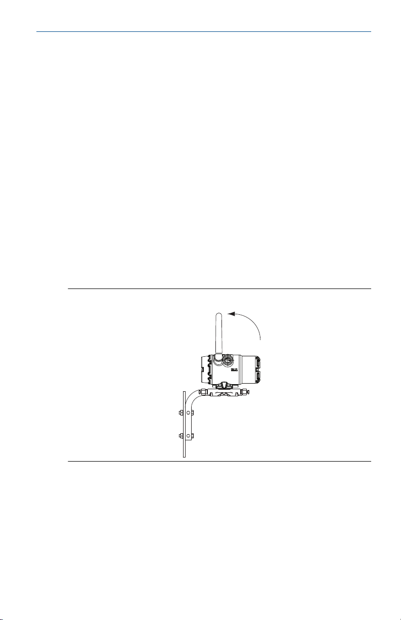
1.2 Antenna position
The antenna should be positioned vertically, either straight up or straight
down, and it should be approximately 3 ft. (1 m) from any large structure,
building, or conductive surface to allow for clear communication to other
devices.
Figure 1-1: Antenna Position
1.3 Conduit entry
Upon installation, ensure each conduit entry is either sealed with a conduit
plug using approved thread sealant, or has an installed conduit fitting or cable
gland with appropriate threaded sealant. Note the conduit entries on the
Emerson 781 Field Link are threaded ½–14 NPT.
Quick Start Guide 5
Page 6
$
$
COMM
P/N 00753-9200-0020
1
2
3
4
CH1 +
CMN
CH2 +
CMN
CH Input Mode:
Dry Contact Only
CH Output Mode:
26VDC Max
100mA Max
Quick Start Guide February 2019
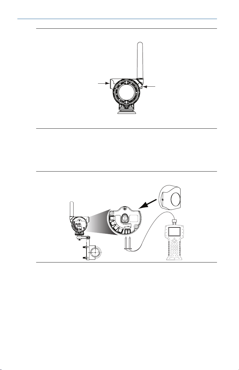
Figure 1-2: Conduit Entry
A. Conduit entry
1.4 Field Communicator connections
The power module needs to be installed before the Field Communicator can
interface with the transmitter. This transmitter uses the Black Power Module;
Order model number 701PBKKF or part number 00753-9220-0001.
Figure 1-3: Connection Diagram
The transmitter and all other wireless devices should not be set up until after
the Wireless Gateway has been installed and is functioning properly.
6 Rosemount 3051S Wireless
Page 7

A
A
February 2019 Quick Start Guide
2 Mount the transmitter
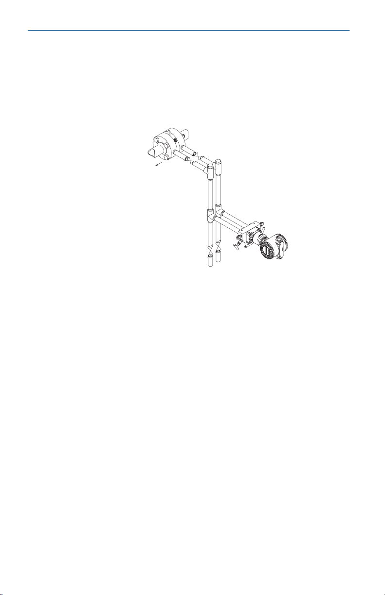
2.1 Liquid flow applications
Procedure
1. Place taps to the side of the line.
2. Mount beside or below the taps.
3. Mount the transmitter so that the drain/vent valves are oriented
upward.
A. Direction of flow
2.2 Gas flow applications
Procedure
1. Place taps in the top or side of the line.
2. Mount beside or above the taps.
A. Direction of flow
Quick Start Guide 7
Page 8
A
Quick Start Guide February 2019
2.3 Steam flow applications
Procedure
1. Place taps to the side of the line.
2. Mount beside or below the taps.
3. Fill impulse lines with water.
A. Direction of flow
8 Rosemount 3051S Wireless
Page 9

February 2019 Quick Start Guide
2.4 Mounting options
Panel mounting
Figure 2-1: Coplanar Flange
Figure 2-2: Traditional Flange
Quick Start Guide 9
Page 10

3.08
(78)
A
6.25
(158)
Quick Start Guide February 2019
Figure 2-3: In-line Device
A. U-bolt bracket
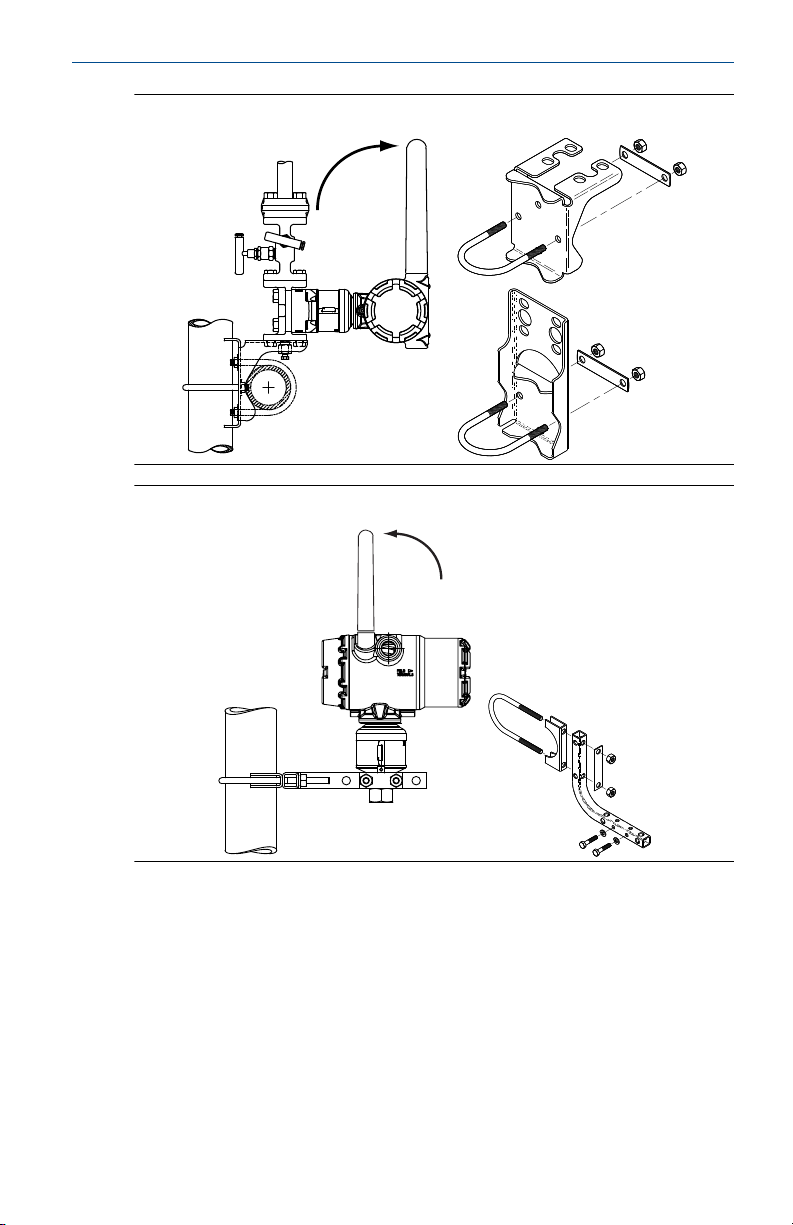
Pipe mounting
Figure 2-4: Coplanar Flange
10 Rosemount 3051S Wireless
Page 11
February 2019 Quick Start Guide
Figure 2-5: Traditional Flange
Figure 2-6: In-line Device
2.5 Bolting considerations
If the transmitter installation requires assembly of a process flange, manifold,
or flange adapters, follow these assembly guidelines to ensure a tight seal for
optimal performance characteristics of the transmitter. Only use bolts
supplied with the transmitter or sold by Emerson™ as spare parts. Figure 2-7
illustrates common transmitter assemblies with the bolt length required for
proper transmitter assembly.
Quick Start Guide 11
Page 12

A
4 × 1.75-in.
(44 mm)
D
4 × 1.75-in.
(44 mm)
4 × 2.25-in.
(57 mm)
C
4 × 1.75-in.
(44 mm)
4
× 1.50-in.
(38 mm)
B
4 × 2.88-in.
(73 mm)
Quick Start Guide February 2019
Figure 2-7: Common Transmitter Assemblies
A. Transmitter with coplanar flange
B. Transmitter with coplanar flange and optional flange adapters
C. Transmitter with traditional flange and optional flange adapters
D. Transmitter with coplanar flange and optional Rosemount Conventional
Manifold and flange adapters
Note
For all other manifolds, contact Customer Central technical support.
Bolts are typically carbon steel or stainless steel. Confirm the material by
viewing the markings on the head of the bolt and referencing Table 2-1 . If
bolt material is not shown in Table 2-1, contact the local Emerson
representative for more information.
Use the following bolt installation procedure:
Procedure
1. Carbon steel bolts do not require lubrication and the stainless steel
bolts are coated with a lubricant to ease installation. However, no
additional lubricant should be applied when installing either type of
bolt.
2. Finger-tighten the bolts.
3. Torque the bolts to the initial torque value using a crossing pattern.
See Table 2-1 for initial torque value.
4. Torque the bolts to the final torque value using the same crossing
pattern. See Table 2-1 for final torque value.
12 Rosemount 3051S Wireless
Page 13

B7M
316
316
316
SW
316
STM
316
R
B8M
A
B
February 2019 Quick Start Guide
5. Verify the flange bolts are protruding through the sensor module
before applying pressure (see Figure 2-8).
Example
Table 2-1: Torque Values for the Flange and Flange Adapter Bolts
Bolt material Head markings Initial torque Final torque
Carbon Steel
300 in-lb 650 in-lb
(CS)
Stainless Steel
150 in-lb 300 in-lb
(SST)
Figure 2-8: Proper Bolt Installation
A. Bolt
B. Sensor module
Quick Start Guide 13
Page 14

A
B
C
D
Quick Start Guide February 2019
2.6 O-rings with flange adapters
WARNING
Failure to install proper flange adapter O-rings may cause process leaks, which
can result in death or serious injury. Only use the O-ring that is designed for its
specific flange adapter.
A. Flange adapter
B. O-ring
C. PTFE-based profile (square)
D. Elastomer profile (round)
Whenever the flange or adapters are removed, visually inspect the O-rings.
Replace them if there are any signs of damage, such as nicks or cuts. If the Orings are replaced, re-torque the flange bolts and alignment screws after
installation to compensate for seating of the O-rings.
2.7 High gain, remote antenna (optional)
The high gain, remote antenna options provide flexibility for mounting the
device based on wireless connectivity, lightning protection, and current work
practices.
14 Rosemount 3051S Wireless
Page 15

February 2019 Quick Start Guide
Figure 2-9: Rosemount 702 Transmitter with High Gain, Remote Antenna
2.7.1 Install the high gain, remote antenna (WN option)
Prerequisites
Find a location where the remote antenna has optimal wireless performance.
Ideally this will be 15–25 ft. (4.6–7.6 m) above the ground or 6 ft. (2 m) above
obstructions or major infrastructure.
Quick Start Guide 15
Page 16

Quick Start Guide February 2019
WARNING
When installing remote mount antennas for the transmitter, always use
established safety procedures to avoid falling or contact with high-power
electrical lines.
Install remote antenna components for the transmitter in compliance with
local and national electrical codes and use best practices for lightning
protection.
Before installing, consult with the local area electrical inspector, electrical
officer, and work area supervisor.
The transmitter remote antenna option is specifically engineered to provide
installation flexibility while optimizing wireless performance and local
spectrum approvals. To maintain wireless performance and avoid noncompliance with spectrum regulations, do not change the length of cable or
the antenna type.
If the supplied remote mount antenna kit is not installed per these
instructions, Emerson is not responsible for wireless performance or noncompliance with spectrum regulations.
Procedure
1. Mount the antenna on a 1.5 to 2-in. pipe mast using the supplied
mounting equipment.
2. Connect the lightning arrestor directly to the top of the Rosemount
Transmitter.
3. Install the grounding lug, lock washer, and nut on top of lightning
arrestor.
4. Connect the antenna to the lightning arrestor using the supplied
LMR-400 coaxial cable ensuring the drip loop is not closer than 1 ft.
(0.3 m) from the lightning arrestor.
5. Use the coaxial sealant to seal each connection between the wireless
field device, lightning arrestor, cable, and antenna.
Note
The remote mount antenna kit includes coaxial sealant for
weatherproofing the cable connections for the lightning arrestor,
antenna, and Rosemount 702 Transmitter. Coaxial sealant must be
applied to guarantee performance of the wireless field network. See
Figure 2-10 for details on how to apply coaxial sealant.
16 Rosemount 3051S Wireless
Page 17

February 2019 Quick Start Guide
Figure 2-10: Applying Coaxial Sealant to Cable Connections
6. Ensure the mounting mast and lightning arrestor are grounded
according to local/national electrical code.
Any spare lengths of coaxial cable should be placed in 12-in. (0.3 m)
coils.
Quick Start Guide 17
Page 18

Quick Start Guide February 2019
3 Connect the power module
Procedure
1. Remove the housing cover on the field terminal side.
2. Connect the black power module.
18 Rosemount 3051S Wireless
Page 19

February 2019 Quick Start Guide
4 Trim the transmitter
Transmitters are shipped fully calibrated per request or by the factory default
of full scale (span = upper range limit).
4.1 Zero trim
A zero trim is a single-point adjustment used for compensating mounting
position and line pressure effects. When performing a zero trim, ensure the
equalizing valve is open and all wet legs are filled to the correct level.
Quick Start Guide 19
Page 20

Quick Start Guide February 2019
5 Close the housing
Procedure
1. Close the housing cover and tighten to safety specification.
2. Always ensure a proper seal by installing the electronics housing
covers so that metal contacts metal, but do not over tighten.
20 Rosemount 3051S Wireless
Page 21

N E T w K
S R C H N G
n e t w k
N E G O T
n e t w k
L I M - O P
n e t w k
O K
February 2019 Quick Start Guide
6 Verify operation
There are four methods available to verify operation:
• Using the optional local display (LCD)
• Using the Field Communicator
• Using the Wireless Gateway’s integrated web interface
• Using AMS Suite Wireless Configurator
If the device was configured with the Network ID and Join Key, and sufficient
time has passed, the transmitter will be connected to the network.
6.1 Local display (LCD display)
The LCD display will show the output values based on the wireless update
rate. Refer to the Rosemount 3051S and 3051SMV Wireless manuals for error
codes and other LCD display messages..
Procedure
Press and hold the Diagnostic button for at least five seconds to display the
TAG, Device ID, Network ID, Network Join Status, and Device Status screens.
Searching for
network
Joining network Connected with
limited bandwidth
Connected
6.2 Field Communicator
For HART Wireless transmitter communication, an appropriate DD is required.
For connecting with a Field Communicator, refer to Field Communicator
connections.
Function
Communications 3, 4 Join Status, Wireless Mode, Join Mode, Number of
Quick Start Guide 21
Fast Key
sequence
Menu Items
Available Neighbors, Number of Advertisements
Heard, Number of Join Attempts
Page 22

Quick Start Guide February 2019
6.3 Wireless Gateway
In the Gateway’s integrated web interface, navigate to the Explorer > Status
page. This page will show whether the device has joined the network and if it
is communicating properly.
Note
It may take several minutes for the device to join the network. See Emerson
Wireless Gateway Quick Start Guide for more information.
Figure 6-1: Gateway Network Settings
6.4 AMS Wireless Configurator
When the device has joined the network, it will appear in AMS Wireless
Configurator as illustrated below.
22 Rosemount 3051S Wireless
Page 23

February 2019 Quick Start Guide
Figure 6-2: AMS Wireless Configurator, Device Explorer Screen
6.5 Troubleshooting
If the device is not joined to the network after power up, verify the correct
configuration of the network ID and join key, and verify the active advertising
has been enabled on the Gateway. The network ID and join key in the device
must match the network ID and join key of the Gateway.
The network ID and join key may be obtained from the Gateway on the Setup
> Network > Settings page on the web interface (see Figure 6-1). The network
ID and join key may be changed in the wireless device by using the following
Fast Key sequence.
Function
Communications 3, 4 Join Status, Wireless Mode, Join Mode, Number of
Quick Start Guide 23
Fast Key
sequence
Menu items
Available Neighbors, Number of Advertisements
Heard, Number of Join Attempts
Page 24

COMM
P/N 00753-9200-0010
Quick Start Guide February 2019
7 Reference information
Figure 7-1: Terminal Diagram
For connecting with a Field Communicator, refer to Figure 1-3.
Table 7-1: HART Fast Key Sequence
Function Fast Key
Device Info
Guided Setup 2, 1 Configure Basic Setup, Zero Sensor Trim, Join Device to
Manual Setup 2, 2 Configure, Manual Setup, Wireless, Pressure, Device
Wireless 2, 2, 1 Network ID, Join Device to Network, Configure Update
(1) If using Rosemount 3051SMV, use the Fast Key sequence 2, 2 and then navigate
to Device Information.
sequence
(1)
2, 2, 9 Manufacturer, Model, Final Assembly Number,
Menu items
Universal, Field Device, Software, Hardware,
Descriptor, Message, Date, Model Number I, II, III, SI
Unit Restriction, Country
Network, Update Rate, Device Display, Alert Setup,
Scaled Variable
Temperatures, Device Information, Display, Scaled
Variable, Other
Rate, Configure Broadcast Power Level, Power Mode,
Power Source
Note
If using Rosemount 3051SMV, use the Fast Key sequence 2, 2 and then
navigate to Device Information.
24 Rosemount 3051S Wireless
Page 25

February 2019 Quick Start Guide
8 Rosemount 3051S and 3051SMV Wireless
Product Certifications
Rev 2.4
European directive information
A copy of the EC Declaration of Conformity can be found at the end of the
Quick Start Guide. The most recent revision of the EC Declaration of
Conformity can be found at Emerson.com/Rosemount.
Telecommunication Compliance
All wireless devices require certification to ensure that they adhere to
regulations regarding the use of the RF spectrum. Nearly every country
requires this type of product certification.
Emerson is working with governmental agencies around the world to supply
fully compliant products and remove the risk of violating country directives or
laws governing wireless device usage.
FCC and IC
This device complies with Part 15 of the FCC Rules. Operation is subject to the
following conditions: This device may not cause harmful interference. This
device must accept any interference received, including interference that may
cause undesired operation. This device must be installed to ensure a
minimum antenna separation distance of 20 cm from all persons.
Ordinary location certification
As standard, the transmitter has been examined and tested to determine that
the design meets the basic electrical, mechanical, and fire protection
requirements by a nationally recognized test laboratory (NRTL) as accredited
by the Federal Occupational Safety and Health Administration (OSHA).
Installing Equipment in North America
The US National Electrical Code (NEC) and the Canadian Electrical Code (CEC)
permit the use of Division marked equipment in Zones and Zone marked
equipment in Divisions. The markings must be suitable for the area
classification, gas, and temperature class. This information is clearly defined in
the respective codes.
8.1
USA
8.1.1 I5 USA Intrinsically Safe (IS), Nonincendive (NI), and DustIgnitionproof (DIP)
Certificate
Quick Start Guide 25
FM18US0009X
Page 26

Quick Start Guide February 2019
Standards
Markings
Special Conditions for Safe Use (X):
1. The Rosemount 3051S and SMV Wireless Transmitters shall only be
2. The transmitter may contain more than 10% aluminum and is
3. The surface resistivity of the antenna is greater than 1GΩ. To avoid
FM Class 3600 – 2011, FM Class 3610 – 2010, FM Class 3611 –
2004, FM Class 3810 – 2005, NEMA® 250 – 2003
IS CL I, DIV 1, GP A, B, C, D; CL II, DIV 1, GP E, F, G; CL III T4; CL 1,
Zone 0 AEx ia IIC T4; NI CL 1, DIV 2, GP A, B, C, D T4; DIP CL II,
DIV 1, GP E, F, G; CL III, T5; T4(–50 °C ≤ Ta ≤ +70 °C)/ T5(–50 °C ≤
Ta ≤ +85 °C); when connected per Rosemount drawing
03151-1000; Type 4X
used with the 701PBKKF Rosemount SmartPower Battery Pack (P/N
00753-9220-0001), Computational Systems Inc Battery Pack (P/N
MHM-89004) or alternatively the Perpetuum Intelligent Power Module
Vibration Harvester (P/N IPM71008).
considered a potential risk of ignition by impact or friction. Care must
be taken into account during installation and use to prevent impact
and friction.
electrostatic charge build-up, it must not be rubbed or cleaned with
solvents or a dry cloth.
8.2 Canada
8.2.1 I6 Canada Intrinsically Safe
Certificate
Standards
Markings
CSA 1143113
CAN/CSA C22.2 No. 0-10, CSA Std C22.2 No. 30-M1986,
CAN/CSA C22.2 No. 94-M91, CSA Std C22.2 No. 142-M1987,
CSA Std C22.2 No. 157-92, ANSI/ISA 12.27.01-2003, CSA Std
C22.2 No. 60529:05
Intrinsically Safe Class I, Division 1; suitable for Class 1, Zone 0,
IIC, T3C; when connected per Rosemount drawing 03151-1010;
Type 4X
8.3 Europe
8.3.1 I1 ATEX Intrinsic Safety
Certificate
Standards
Markings
26 Rosemount 3051S Wireless
Baseefa13ATEX0127X
EN 60079-0: 2012, EN 60079-11: 2012
II 1 G Ex ia IIC T4 Ga, T4(–60 °C ≤ Ta ≤ +70 °C)
Page 27

February 2019 Quick Start Guide
Special Conditions for Safe Use (X):
1. The Rosemount 3051S Wireless and Rosemount 3051SMV Wireless
enclosure may be made of aluminum alloy and given a protective
polyurethane paint finish; however, care should be taken to protect it
from impact or abrasion if located in a zone 0 area.
2. The surface resistivity of the antenna is greater than 1 GΩ. To avoid
electrostatic charge build-up, it must not be rubbed or cleaned with
solvents or dry cloth.
8.4 International
8.4.1 I7 IECEx Intrinsic Safety
8.5
Certificate
Standards
Markings
Special Conditions for Safe Use (X):
1. The Rosemount 3051S Wireless and Rosemount 3051SMV Wireless
enclosure may be made of aluminum alloy and given a protective
polyurethane paint finish; however, care should be taken to protect it
from impact or abrasion if located in a zone 0 area.
2. The surface resistivity of the antenna is greater than 1GΩ . To avoid
electrostatic charge build-up, it must not be rubbed or cleaned with
solvents or dry cloth.
Brazil
IECEx BAS 13.0068X
IEC 60079-0:2011, IEC 60079-11:2011
Ex ia IIC T4 Ga, T4(–60 °C ≤ Ta ≤ +70 °C)
8.5.1 I2 INMETRO Intrinsic Safety
Certificate
Standards
Markings
Special Condition for Safe Use (X):
1. See certificate.
UL-BR 14.0760X
ABNT NBR IEC60079-0:2008 + Errata 1:2011, ABNT NBR
IEC60079-11: 2009
Ex ia IIC T4 Ga, T4(–60 °C ≤ Ta ≤ +70 °C)
8.6
China
8.6.1 I3 China Intrinsic Safety
Certificate
Quick Start Guide 27
3051S Wireless: GYJ161250X
3051SFX: GYJ16.1465X [flow meters]
Page 28

Quick Start Guide February 2019
Standards
Markings
Special Condition for Safe Use (X):
1. See appropriate certificate.
Note
Not currently available on the Rosemount 3051S MultiVariable Wireless
Transmitter.
GB3836.1-2010, GB3836.4-2010, GB3836.20-2010
Ex ia IIC T4 Ga, T4(–60~70 °C)
8.7 Japan
8.7.1 I4 TIIS Intrinsically Safe
Certificate
Markings
Note
Not currently available on the Rosemount 3051S MultiVariable Wireless
Transmitter.
TC18649, TC18650, TC18657
Ex ia IIC T4, T4(–20~60 °C)
8.8 EAC - Belarus, Kazakhstan, Russia
8.8.1 IM EAC Intrinsic Safety
Certificate
Markings
TC RU C-US.AA87.B.00378
0Ex ia IIC T4 Ga X (–60 °C ≤ Ta ≤ +70 °C)
Special Condition for Safe Use (X):
1. See certificate for special conditions.
Note
Not currently available on the Rosemount 3051S MultiVariable Wireless
Transmitter.
8.9
Republic of Korea
8.9.1 IP Korea Intrinsic Safety
Certificates
Markings
Note
Not currently available on the Rosemount 3051S MultiVariable Wireless
Transmitter.
28 Rosemount 3051S Wireless
12-KB4BO-0202X, 12-KB4BO-0203X
Ex ia IIC T4, (–60 °C ≤ Ta ≤ +70 °C)
Page 29

February 2019 Quick Start Guide
Special Condition for Safe Use (X):
1. See certificate for special conditions.
8.10 Combinations
KQ
Combination of I1, I5, and I6
Quick Start Guide 29
Page 30

EU Declaration of Conformity
No: RMD 1099 Rev. I
Page 1 of 3
We,
Rosemount, Inc.
8200 Market Boulevard
Chanhassen, MN 55317-9685
USA
declare under our sole responsibility that the product,
Rosemount™ 3051S & 300S Wireless Pressure Transmitters,
3051SFx Wireless Flowmeter Transmitters,
and 3051SMV & 300SMV Wireless Pressure Transmitters
manufactured by,
Rosemount, Inc.
8200 Market Boulevard
Chanhassen, MN 55317-9685
USA
to which this declaration relates, is in conformity with the provisions of the European Union
Directives, including the latest amendments, as shown in the attached schedule.
Assumption of conformity is based on the application of the harmonized standards and, when
applicable or required, a European Union notified body certification, as shown in the attached
schedule.
(signature)
Vice President of Global Quality
(function)
Chris LaPoint
(name)
1-Feb-19; Shakopee, MN USA
(date of issue & place)
Quick Start Guide February 2019
8.11 Rosemount 3051S Wireless Declaration of Conformity
30 Rosemount 3051S Wireless
Page 31

EU Declaration of Conformity
No: RMD 1099 Rev. I
Page 2 of 3
EMC Directive (2014/30/EU)
Harmonized Standards:
EN 61326-1:2013
EN 61326-2-3:2013
Radio Equipment Directive (RED) (2014/53/EU)
Harmonized Standards:
EN 300 328 V2.1.1
EN 301 489-1 V2.2.0
EN 301 489-17 V3.2.0
EN 61010-1: 2010
EN 62311: 2008
PED Directive (2014/68/EU)
Rosemount™ 3051S_CA4; 3051S_CD2, 3, 4, 5 (also with P0 & P9 option)
QS Certificate of Assessment – EC Certificate No. 12698-2018-CE-ACCREDIA
Module H Conformity Assessment
Other Standards Used:
ANSI / ISA 61010-1:2004
IEC 60770-1:1999
Note – previous PED Certificate No. 59552-2009-CE-HOU-DNV
All other Rosemount™ 3051S & 3051SMV Pressure Transmitters
Sound Engineering Practice
Transmitter Attachments: Diaphragm Seal, Process Flange, or Manifold
Sound Engineering Practice
Rosemount 3051SFx Series Flowmeter Pressure Transmitters
Refer to Declaration of Conformity DSI1000
February 2019 Quick Start Guide
Quick Start Guide 31
Page 32

EU Declaration of Conformity
No: RMD 1099 Rev. I
Page 3 of 3
ATEX Directive (2014/34/EU)
Baseefa13ATEX0127X – Intrinsic Safety Certificate
Equipment Group II, Category 1 G
Ex ia IIC T4 Ga
Harmonized Standards:
EN 60079-0:2012+A11:2013
EN 60079-11:2012
PED Notified Body
DNV GL Business Assurance Italia S.r.l. [Notified Body Number: 0496]
Via Energy Park 14, N-20871
Vimercate (MB), Italy
Note – equipment manufactured prior to 20 October 2018 may be marked with the previous PED
Notified Body number; previous PED Notified Body information was as follows:
Det Norske Veritas (DNV) [Notified Body Number: 0575]
Veritasveien 1, N-1322
Hovik, Norway
ATEX Notified Body
SGS FIMCO OY [Notified Body Number: 0598]
P.O. Box 30 (Särkiniementie 3)
00211 HELSINKI
Finland
ATEX Notified Body for Quality Assurance
SGS FIMCO OY [Notified Body Number: 0598]
P.O. Box 30 (Särkiniementie 3)
00211 HELSINKI
Finland
Quick Start Guide February 2019
32 Rosemount 3051S Wireless
Page 33

ᴹ
China RoHS
㇑᧗⢙䍘䎵䗷ᴰབྷ⎃ᓖ䲀٬Ⲵ䜘Ԧරࡇ㺘
Rosemount 3051S
List of Rosemount 3051S Parts with China RoHS Concentration above MCVs
䜘Ԧ〠
Part Name
ᴹᇣ⢙䍘
/ Hazardous Substances
䫵
Lead
(Pb)
⊎
Mercury
(Hg)
䭹
Cadmium
(Cd)
ޝԧ䬜
Hexavalent
Chromium
(Cr +6)
ཊⓤ㚄㤟
Polybrominated
biphenyls
(PBB)
ཊⓤ㚄㤟䟊
Polybrominated
diphenyl ethers
(PBDE)
⭥ᆀ㓴Ԧ
Electronics
Assembly
X O O O O O
༣փ㓴Ԧ
Housing
Assembly
X O O X O O
Րᝏಘ㓴Ԧ
Sensor
Assembly
X O O X O O
ᵜ㺘Ṭ㌫ᦞ
SJ/T11364
Ⲵ㿴ᇊ㘼ࡦ
This table is proposed in accordance with the provision of SJ/T11364.
O:
Ѫ䈕䜘ԦⲴᡰᴹ൷䍘ᶀᯉѝ䈕ᴹᇣ⢙䍘Ⲵ䟿൷վҾ
GB/T 26572
ᡰ㿴ᇊⲴ䲀䟿㾱≲
O: Indicate that said hazardous substance in all of the homogeneous materials for this part is below the limit requirement of
GB/T 26572.
X:
Ѫ൘䈕䜘Ԧᡰ֯⭘Ⲵᡰᴹ൷䍘ᶀᯉ䟼ˈ㠣ቁᴹа㊫൷䍘ᶀᯉѝ䈕ᴹᇣ⢙䍘Ⲵ䟿儈Ҿ
GB/T 26572
ᡰ㿴ᇊⲴ䲀䟿㾱≲
X: Indicate that said hazardous substance contained in at least one of the homogeneous materials used for this part is above
the limit requirement of GB/T 26572.
February 2019 Quick Start Guide
8.12 China RoHS
Quick Start Guide 33
Page 34

Quick Start Guide February 2019
34 Rosemount 3051S Wireless
Page 35

February 2019 Quick Start Guide
Quick Start Guide 35
Page 36

*00825-0200-4802*
00825-0200-4802, Rev. HE
Quick Start Guide
February 2019
Global Headquarters
Emerson Automation Solutions
6021 Innovation Blvd.
Shakopee, MN 55379, USA
+1 800 999 9307 or +1 952 906 8888
+1 952 949 7001
RFQ.RMD-RCC@Emerson.com
Latin America Regional Office
Emerson Automation Solutions
1300 Concord Terrace, Suite 400
Sunrise, FL 33323, USA
+1 954 846 5030
+1 954 846 5121
RFQ.RMD-RCC@Emerson.com
Asia Pacific Regional Office
Emerson Automation Solutions
1 Pandan Crescent
Singapore 128461
+65 6777 8211
+65 6777 0947
Enquiries@AP.Emerson.com
North America Regional Office
Emerson Automation Solutions
8200 Market Blvd.
Chanhassen, MN 55317, USA
+1 800 999 9307 or +1 952 906 8888
+1 952 949 7001
RMT-NA.RCCRF@Emerson.com
Europe Regional Office
Emerson Automation Solutions Europe
GmbH
Neuhofstrasse 19a P.O. Box 1046
CH 6340 Baar
Switzerland
+41 (0) 41 768 6111
+41 (0) 41 768 6300
RFQ.RMD-RCC@Emerson.com
Middle East and Africa Regional Office
Emerson Automation Solutions
Emerson FZE P.O. Box 17033
Jebel Ali Free Zone - South 2
Dubai, United Arab Emirates
+971 4 8118100
+971 4 8865465
RFQ.RMTMEA@Emerson.com
Linkedin.com/company/Emerson-
Automation-Solutions
Twitter.com/Rosemount_News
Facebook.com/Rosemount
Youtube.com/user/
RosemountMeasurement
Google.com/+RosemountMeasurement
©
2019 Emerson. All rights reserved.
Emerson Terms and Conditions of Sale are
available upon request. The Emerson logo is a
trademark and service mark of Emerson Electric
Co. Rosemount is mark of one of the Emerson
family of companies. All other marks are the
property of their respective owners.
 Loading...