

Emerson Rosemount 3051 Series, Rosemount 3051CF Series, 3051T, 3051S Quick Start Manual

Quick Start Guide
00825-0100-4797, Rev FD
February 2019
Rosemount™ 3051 Pressure Transmitter
and Rosemount 3051CF Series Flow
Meter
with PROFIBUS® PA Protocol

Quick Start Guide February 2019
NOTICE
This installation guide provides basic guidelines for Rosemount 3051 Transmitters. It does not provide
instructions for configuration, diagnostics, maintenance, service, troubleshooting, Explosion-Proof,
Flame-Proof, or intrinsically safe (I.S.) installations. Refer to the Rosemount 3051 Reference Manual for
more instruction. This manual is also available electronically on EmersonProcess.com/Rosemount.
WARNING
Explosions could result in death or serious injury.
Installation of this transmitter in an explosive environment must be in accordance with the appropriate
local, national, and international standards, codes, and practices. Review the approvals section of the
Rosemount 3051 Reference Manual for any restrictions associated with a safe installation.
Do not remove the transmitter cover in explosive atmospheres when the circuit is live.
Process leaks could result in death or serious injury.
To avoid process leaks, only use the O-ring designed to seal with the corresponding flange adapter.
Electrical shock could cause death or serious injury.
Avoid contact with the leads and terminals. High voltage that may be present on leads can cause
electrical shock.
Conduit/cable entries
Unless otherwise marked, the conduit/cable entries in the housing enclosure use a ½–14 NPT form.
Only use plugs, adapters, glands, or conduit with a compatible thread form when closing these entries.
Contents
Mount the transmitter................................... 3
Consider housing rotation............................12
Set jumpers and switches.............................13
Connect wiring and power up...................... 14
2 Emerson.com/Rosemount
Basic configuration...................................... 18
Trim the transmitter.................................... 21
Product Certifications.................................. 22
February 2019 Quick Start Guide
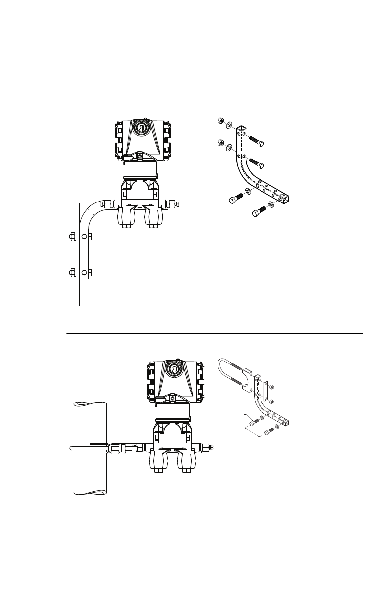
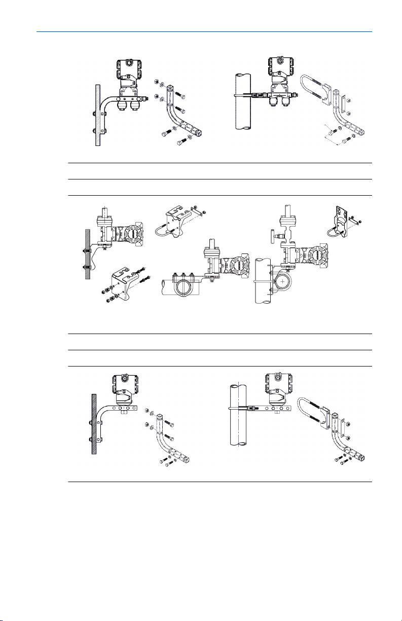
1 Mount the transmitter
Figure 1-1: Panel Mount Coplanar Flange
5/16 x 1½ panel bolts are customer supplied.
Figure 1-2: Pipe Mount Coplanar Flange
Quick Start Guide 3
Quick Start Guide February 2019
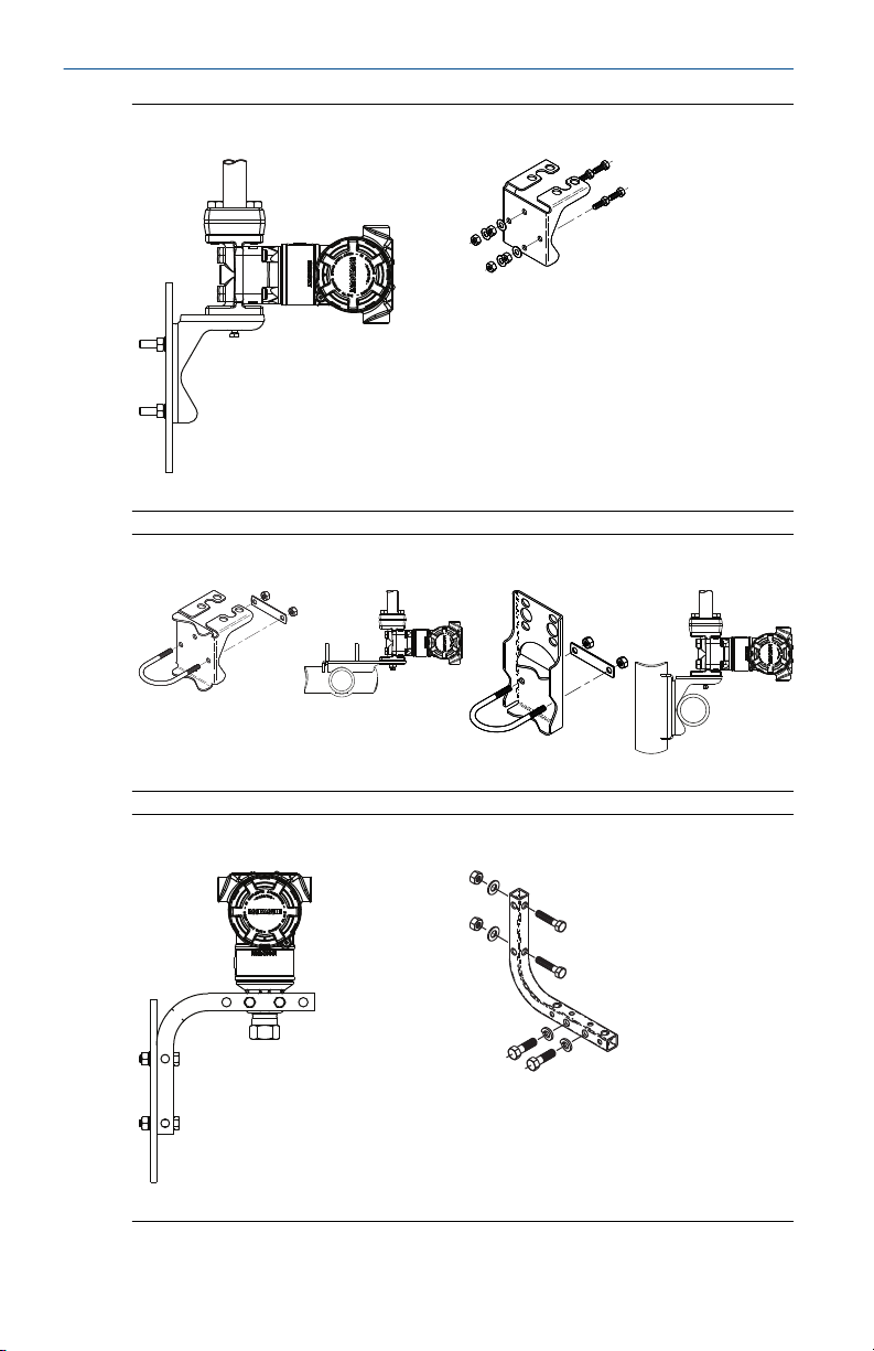
Figure 1-3: Panel Mount Traditional Flange
Figure 1-4: Pipe Mount Traditional Flange
Figure 1-5: Panel Mount Rosemount™ 3051T
4 Emerson.com/Rosemount
Flow
February 2019 Quick Start Guide
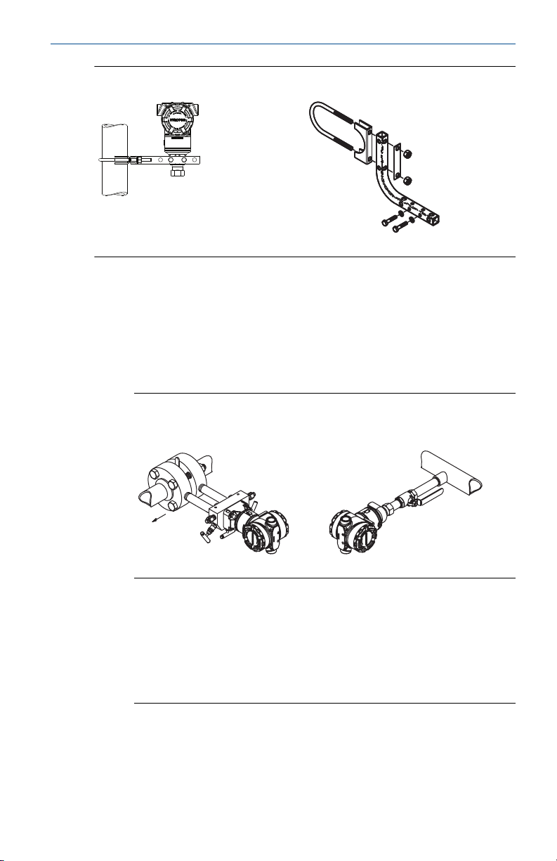
Figure 1-6: Pipe Mount Rosemount 3051T
1.1 Mount the transmitter in liquid applications
Procedure
1. Place taps to the side of the line.
2. Mount beside or below the taps.
3. Mount the transmitter so the drain/vent valves are oriented upward.
Figure 1-7: Mounting the Transmitter in Liquid Applications
Coplanar In-line
1.2 Mount the transmitter in gas applications
Procedure
1. Place taps in the top or side of the line.
2. Mount beside or above the taps.
Figure 1-8: Mounting the Transmitter in Gas Applications
Coplanar
Quick Start Guide 5
Inline
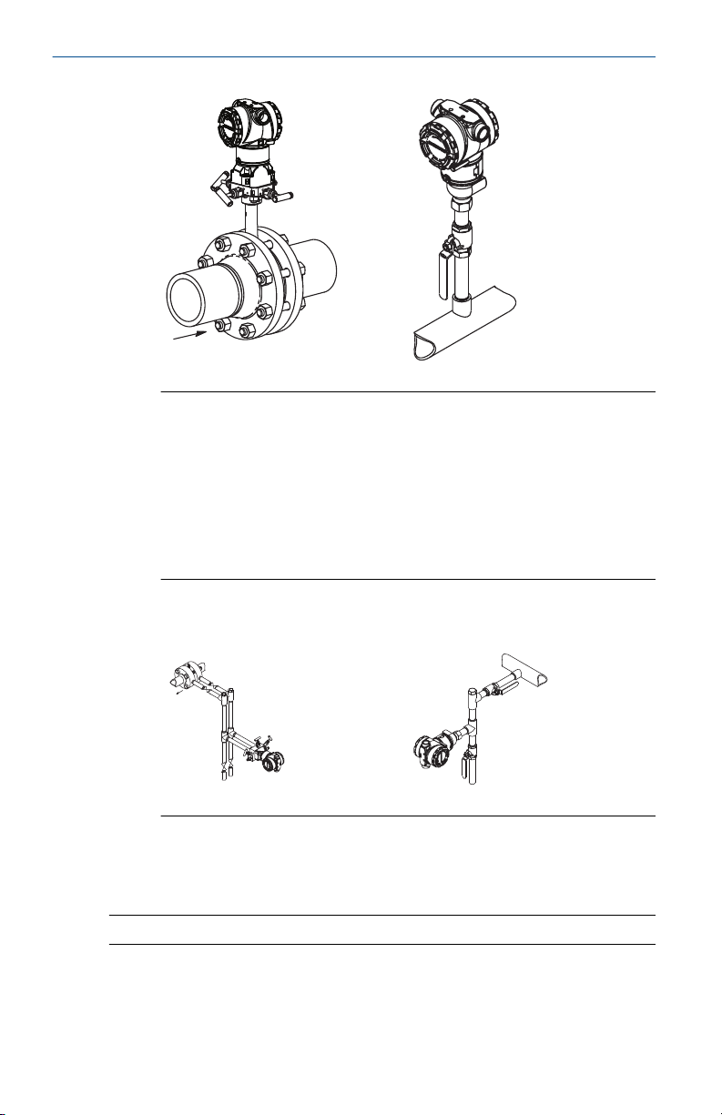
Flow
Flow
Quick Start Guide February 2019
1.3 Mount the transmitter in steam applications
Procedure
1. Place taps to the side of the line.
2. Mount beside or below the taps.
3. Fill impulse lines with water.
Figure 1-9: Mounting the Transmitter in Steam Applications
Coplanar
In-line
1.4 Mounting options
Coplanar flange
Panel mount
6 Emerson.com/Rosemount
(1)
Pipe mount
February 2019 Quick Start Guide
Traditional flange
Panel mount
(2)
Rosemount 3051T
Panel mount
(3)
Pipe mount
Pipe mount
(1)
Panel bolts are customer supplied.
(2) Panel bolts are customer supplied.
(3) Panel bolts are customer supplied.
Quick Start Guide 7
B
4 × 2.88-in. (73 mm)
A
4 × 1.75-in. (44 mm)
C
4 × 1.75-in.
(44 mm)
4 × 1.75-in.
(44 mm)
D
4 × 1.75-in. (44 mm)
4 × 2.25-in. (57 mm)
Quick Start Guide February 2019
1.5 Bolting considerations
If the transmitter installation requires assembly of the process flanges,
manifolds, or flange adapters, follow these assembly guidelines to ensure a
tight seal for optimal performance characteristics of the transmitters. Use
only bolts supplied with the transmitter or sold by Emerson as spare parts.
Figure 1-10 illustrates common transmitter assemblies with the bolt length
required for proper transmitter assembly.
Figure 1-10: Common Transmitter Assemblies
A. Transmitter with coplanar flange
B. Transmitter with coplanar flange and optional flange adapters
C. Transmitter with traditional flange and optional flange adapters
D. Transmitter with coplanar flange and optional manifold and flange
adapters
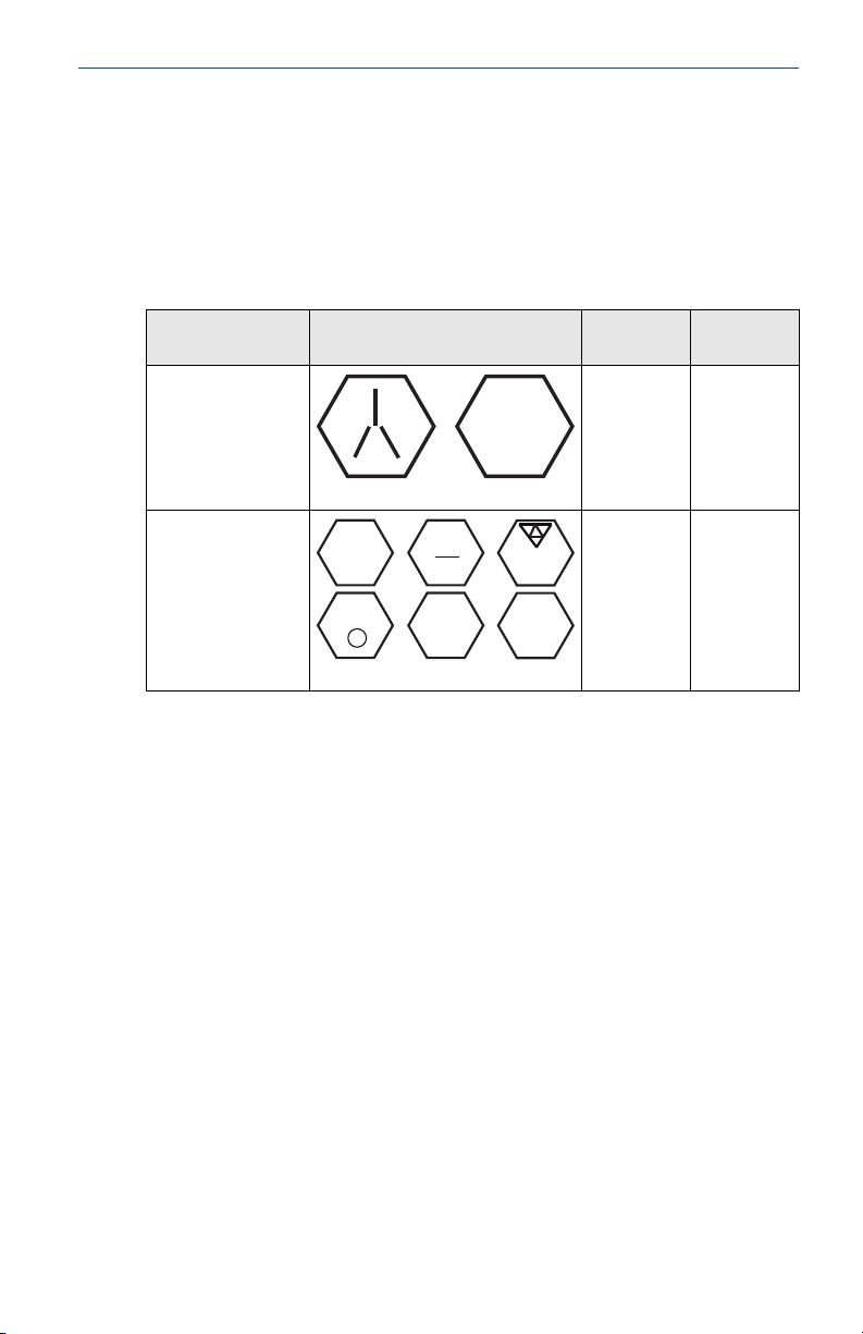
Bolts are typically carbon steel (CS) or stainless steel (SST). Confirm the
material by viewing the markings on the head of the bolt and referencing
Table 1-1. If bolt material is not shown in Table 1-1, contact a local Emerson
representative for more information.
Procedure
1. Carbon steel bolts do not require lubrication and the stainless steel
bolts are coated with a lubricant to ease installation. However, no
additional lubricant should be applied when installing either type of
bolt.
8 Emerson.com/Rosemount
2. Finger-tighten the bolts.
3. Torque the bolts to the initial torque value using a crossing pattern.
See Table 1-1 for initial torque value.
B7M
316
316
316
SW
316
STM
316
R
B8M
February 2019 Quick Start Guide
4. Torque the bolts to the final torque value using the same crossing
pattern. See Table 1-1 for final torque value.
5. Verify the flange bolts are protruding through the isolator plate before
applying pressure.
Example
Table 1-1: Torque Values for the Coplanar Flange and Flange Adapter
Bolts
Bolt material Head markings Initial
torque
CS
300 in-lb 650 in-lb
SST
150 in-lb 300 in-lb
Final
torque
Quick Start Guide 9

A
B
C
D
Rosemount 3051S/3051/2051
Quick Start Guide February 2019
1.6 O-rings with flange adapters
WARNING
Failure to install proper flange adapter O-rings may cause process leaks, which
can result in death or serious injury. The two flange adapters are distinguished
by unique O-ring grooves. Only use the O-ring that is designed for its specific
flange adapter, as shown below.
Figure 1-11: O-ring Location
A. Flange adapter
B. O-ring
C. PFTE-based profile (square)
D. Elastomer profile (round)
Whenever the flanges or adapters are removed, visually inspect the O-rings.
Replace them if there are any signs of damage, such as nicks or cuts. If you
replace the O-rings, re-torque the flange bolts and alignment screws after
installation to compensate for seating of the PTFE O-ring.
1.7
1.8
10 Emerson.com/Rosemount
Environmental seal for housing
Thread sealing (PFTE) tape or paste on male threads of conduit is required to
provide a water/dust tight conduit seals and meets requirements of NEMA
Type 4X, IP66, and IP68. Consult factory if other Ingress Protection ratings are
required.
For M20 threads, install conduit plugs to full thread engagement or until
mechanical resistance is met.
In-line gage transmitter orientation
The low side pressure port (atmospheric reference) on the in-line gage
transmitter is located in the neck of the transmitter, behind the housing. The
®
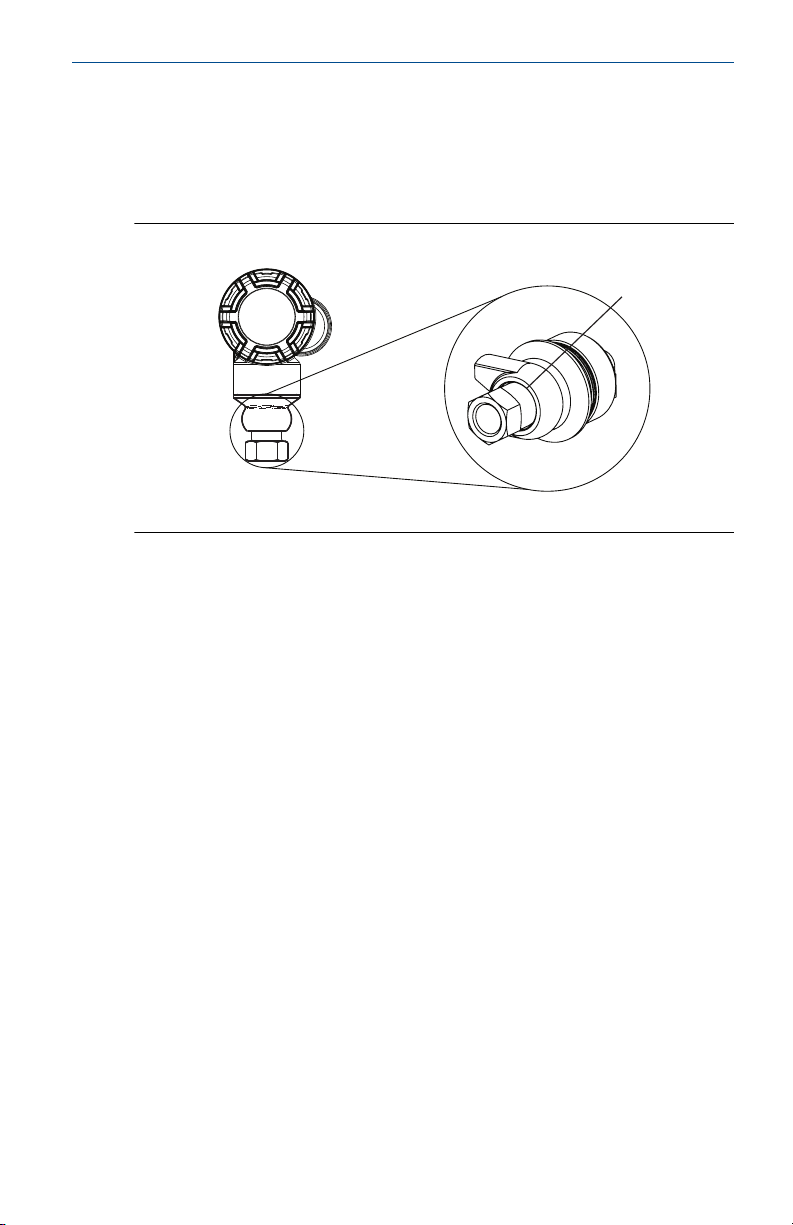
A
February 2019 Quick Start Guide
vent path is between the housing and sensor of the transmitter (see Figure
1-12).
Keep the vent path free of any obstruction, including but not limited to paint,
dust, and lubrication by mounting the transmitter so that the process can
drain away.
Figure 1-12: In-line Gage Low Side Pressure Port
A. Low side pressure port (atmospheric reference)
Quick Start Guide 11
A
Quick Start Guide February 2019
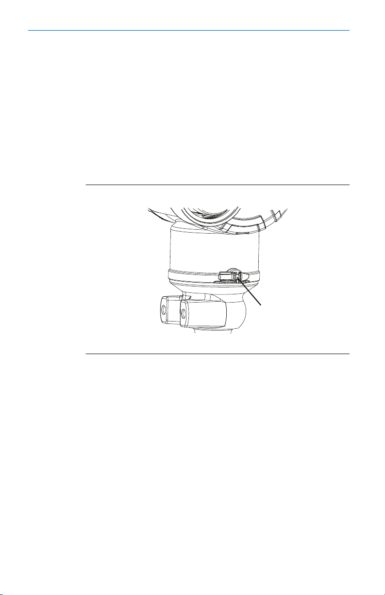
2 Consider housing rotation
To improve visibility of optional LCD display:
Procedure
1. Loosen the housing rotation screw.
2. First rotate the housing clockwise to the desired location. If the desired
location cannot be achieved due to thread limit, rotate the housing
counter clockwise to the desired location (up to 360° from thread
limit).
3. Re-tighten the housing rotation screw (see Figure 2-1).
Figure 2-1: Housing Rotation
A. Housing rotation screw (5/64-in. hex wrench required)
12 Emerson.com/Rosemount
February 2019 Quick Start Guide
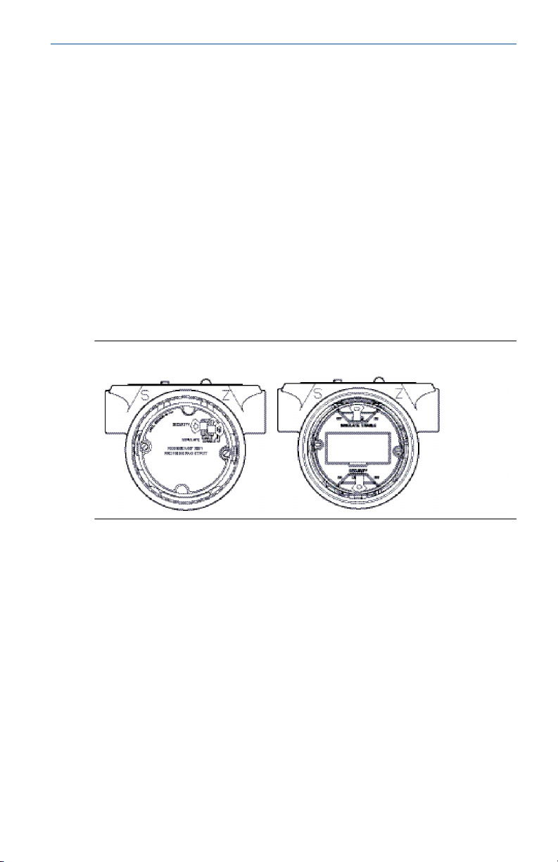
3 Set jumpers and switches
3.1 Security
After the transmitter is configured, you may want to protect the configuration
data from unwarranted changes. Each transmitter is equipped with a security
jumper that can be positioned ON to prevent the accidental or deliberate
change of configuration data. The jumper is labeled “Security”. The security
jumper also prevents changes made using the Local Operator Interface.
3.2 Simulate
The simulate jumper is used in conjunction with the analog input (AI) block.
This jumper is used to simulate the pressure measurement and is used as a
lock-out feature for the AI block. to enable the simulate feature, the jumper
must be moved to the “ON” position after power is applied. This feature
prevents the transmitter from being accidentally left in simulate mode.
Figure 3-1: Transmitter Jumper Locations
Quick Start Guide 13

Quick Start Guide February 2019
4 Connect wiring and power up
Use the following steps to wire the transmitter:
Procedure
1. Remove the housing cover on the field terminals side.
2. Connect the power leads to the terminals indicated on the terminal
block label.
• Power terminals are polarity insensitive - connect positive or
negative to either terminal.
3. Ensure full contact with Terminal Block screw and washer. When using
a direct wiring method, wrap wire clockwise to ensure it is in place
when tightening the terminal block screw.
Note
The use of a pin or a ferrule wire terminal is not recommended as the
connection may be more susceptible to loosening over time or under
vibration.
4. Ensure proper grounding. It is important that the instrument cable
shield:
• Be trimmed close and insulated from touching the transmitter
housing
• Be connected to the next shield if cable is routed through a
junction box
• Be connected to a good earth ground at the power supply end
5. Plug and seal unused conduit connections.
6. If applicable, install wiring with a drip loop. Arrange the drip loop
so the bottom is lower than the conduit connections and the
transmitter housing.
7. Replace the housing cover.
14 Emerson.com/Rosemount
 Loading...