

Page 1
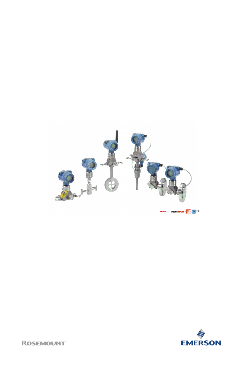
Quick Start Guide
00825-0100-4801, Rev PC
November2024
Rosemount™ 3051S Series Pressure
Transmitter and Rosemount 3051SF
Series Flow Meter
with HART® Protocol
Page 2

Quick Start Guide November2024
Safety messages
This document provides basic guidelines for Rosemount™ 3051S Series Pressure
Transmitters. It also provides the basic electronic guidelines for the:
• Rosemount 3051SFA
• Rosemount 3051SFC
• Rosemount 3051SFP
It does not provide instructions for diagnostics, maintenance, service, or troubleshooting.
Refer to the Reference Manual for more instruction. This document is also available
electronically on
Emerson.com.
WARNING
Explosion
Explosions could result in death or serious injury.
Do not remove the transmitter cover in explosive atmospheres when the circuit is live.
Both transmitter covers must be fully engaged to meet explosion-proof requirements.
Ensure device is installed in accordance with intrinsically safe or non-incendive field practices.
WARNING
Process leak
Process leaks could result in death or serious injury.
To avoid process leaks, only use the O-ring designed to seal with the corresponding flange
adapter.
WARNING
Electric shock
Electrical shock could cause death or serious injury.
Avoid contact with the leads and terminals. High voltage that may be present on leads can
cause electrical shock.
WARNING
Refer to the Product certifications section of this Quick Start Guide documentation when using
the RFID tag (option code Y3) for required installation conditions.
Contents
Mounting the transmitter........................................................................................................... 5
Rotate housing........................................................................................................................... 12
Set switches and jumpers......................................................................................................... 13
2 www.Emerson.com
Page 3

November2024 Quick Start Guide
Connect wiring and power up..................................................................................................15
Verify configuration................................................................................................................... 24
Trim the transmitter.................................................................................................................. 28
Safety instrumented systems installation...............................................................................30
Rosemount 3051S/3051SFx/3051S-ERS.................................................................................. 31
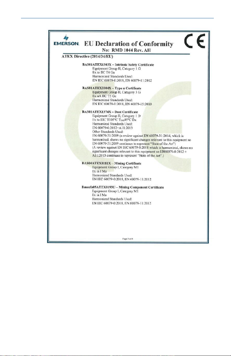
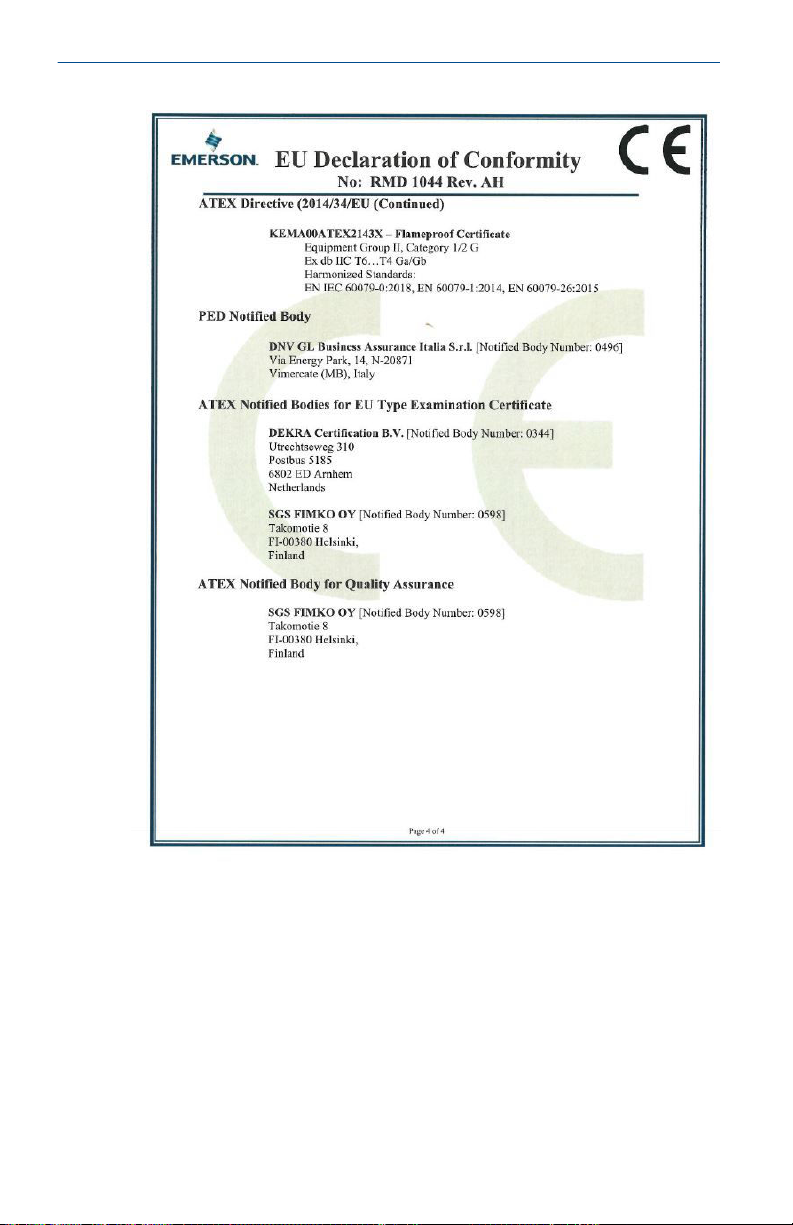
Declaration of Conformity........................................................................................................ 53
China RoHS................................................................................................................................. 57
www.Emerson.com 3
Page 4

Quick Start Guide November2024
4 www.Emerson.com
Page 5
A
November2024 Quick Start Guide
1 Mounting the transmitter
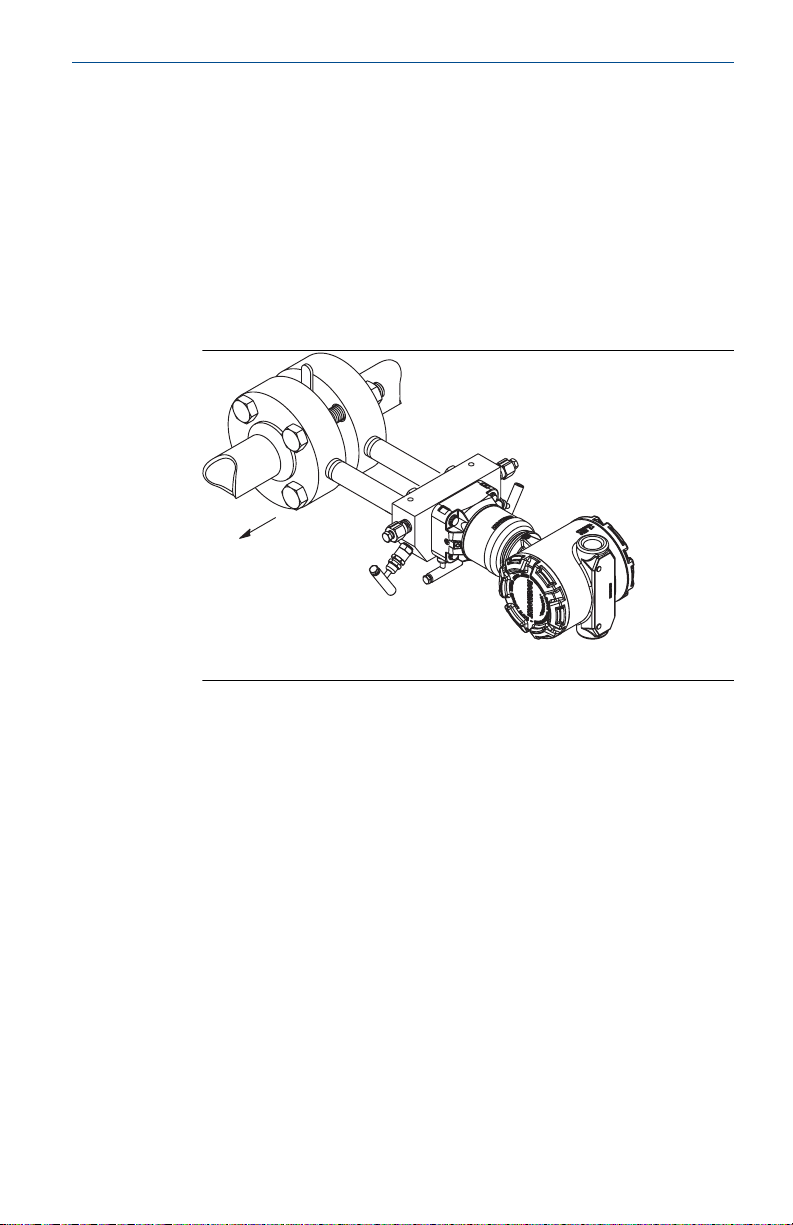
1.1 Liquid flow applications
Procedure
1. Place taps to the side of the line.
2. Mount beside or below the taps.
3. When mounting the transmitter, orientate the drain/vent
valves upward.
A. Direction of flow
1.2
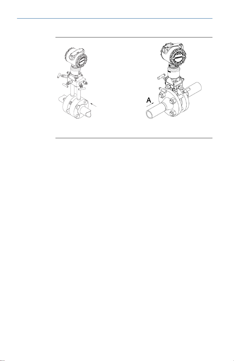
Gas flow applications
Procedure
1. Place taps in the top or side of the line.
www.Emerson.com 5
Page 6
A
Quick Start Guide November2024
2. Mount beside or above the taps.
A. Direction of flow
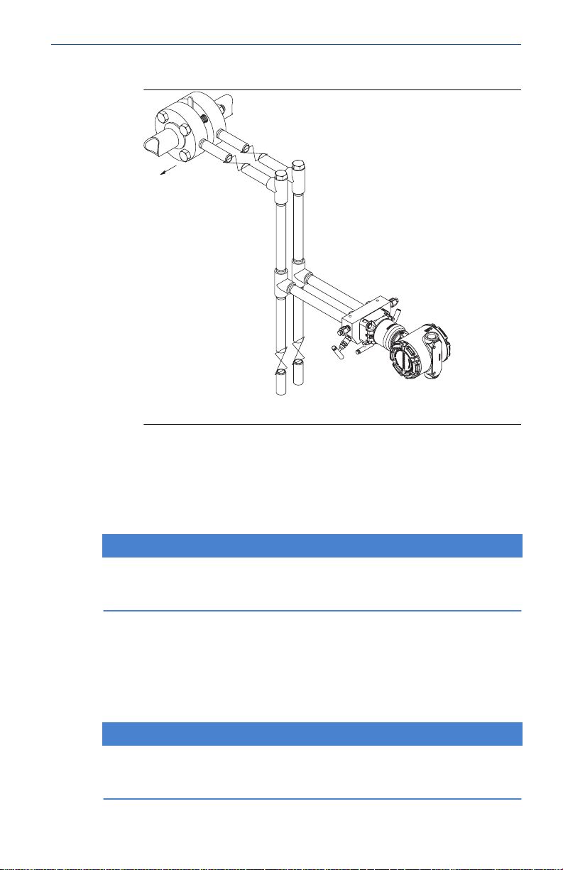
1.3 Steam flow applications
Procedure
1. Place taps to the side of the line.
2. Mount beside or below the taps.
6 www.Emerson.com
Page 7
A
November2024 Quick Start Guide
3. Fill impulse lines with water.
A. Direction of flow
1.4 Using a mounting bracket
If the transmitter requires a mounting bracket, use the following
images for instructions on how to properly mount the transmitter
using the Emerson provided mounting brackets.
NOTICE
Use only bolts provided with the transmitter or sold as Emerson
spare parts.
1.5
Bolting considerations
If the transmitter installation requires assembly of a process flange,
manifold, or flange adapters, follow these assembly guidelines
to ensure a tight seal for optimal transmitter performance
characteristics.
NOTICE
Only use bolts supplied with the transmitter or sold by Emerson as
spare parts.
www.Emerson.com 7
Page 8
A
4 × 1.75-in.
(44 mm)
D
4 × 1.75-in.
(44 mm)
4 × 2.25-in.
(57 mm)
C
4
× 1.75-in.
(44 mm)
4
× 1.50-in.
(38 mm)
B
4 × 2.88-in.
(73 mm)
B7M
316
316
316
SW
316
STM
316
R
B8M
Quick Start Guide November2024
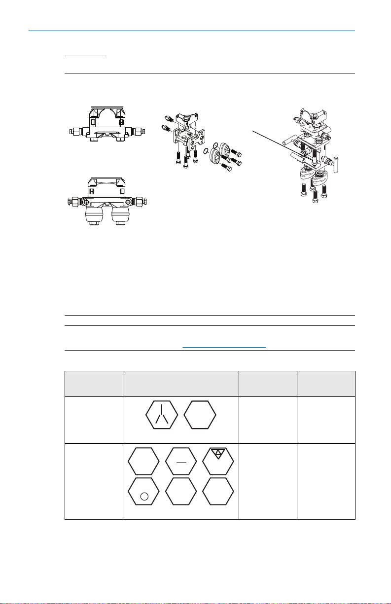
Figure 1-1 illustrates common transmitter assemblies with the bolt
length required for proper transmitter assembly.
Figure 1-1: Common transmitter assemblies
A. Transmitter with Coplanar™ flange
B. Transmitter with Coplanar flange and optional flange adapters
C. Transmitter with traditional flange and optional flange adapters
D. Transmitter with Coplanar flange and optional Rosemount
Conventional Manifold and flange adapters
Note
For all other manifolds, visit
Emerson.com/global.
Table 1-1: Torque values for the flange and flange adapter bolts
Bolt
material
Carbon steel
(CS)
Stainless
steel (SST)
Bolts are typically carbon steel or stainless steel. Confirm the material
by viewing the markings on the head of the bolt and referencing
8 www.Emerson.com
Head markings Initial
torque
300 in-lb. 650 in-lb.
150 in-lb. 300 in-lb.
Final torque
Page 9

A
B
November2024 Quick Start Guide
Table 1-1. If bolt material is not shown in Table 1-1, contact your local
Emerson representative for more information.
NOTICE
Do not apply additional lubricant when installing either type of bolt.
Carbon steel bolts do not require lubrication. Stainless steel bolts are
coated with a lubricant to ease installation.
To install bolts:
Procedure
1. Finger-tighten the bolts.
2. Torque the bolts to the initial torque value using a crossing
pattern.
Table 1-1 for initial torque value.
See
3. Torque the bolts to the final torque value using the same
crossing pattern.
See Table 1-1 for final torque value.
4. Verify the flange bolts are protruding through the sensor
module before applying pressure.
Figure 1-2.
See
Example
Figure 1-2: Proper bolt installation
A. Bolt
B. Sensor module
www.Emerson.com 9
Page 10
A
B
C
D
Quick Start Guide November2024
1.6 O-rings with flange adapters
WARNING
Process leak
Improperly installed flange adapter O-rings could cause process
leaks which could result in death or serious injury.
Only use the O-ring that is designed for its specific flange adapter.
WARNING
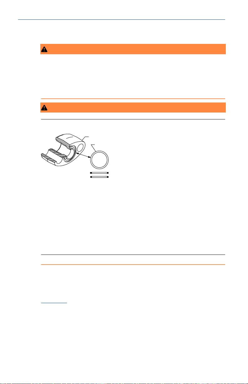
Figure 1-3: O-Ring flange adapter
A. Flange adapter
B. O-ring
C. PTFE-based profile (square)
D. Elastomer profile (round)
Whenever the flange or adapters are removed, visually inspect the Orings. Replace them if there are any signs of damage, such as nicks or
cuts. If the O-rings are replaced, re-torque the flange bolts and
alignment screws after installation to compensate for seating of the
O-rings.
1.7
10 www.Emerson.com
In-line gage transmitter orientation
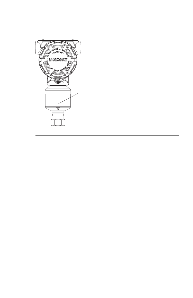
The low side pressure port (atmospheric reference) on the in-line
gage transmitter is located under the sensor module neck label (see
Figure 1-4).
Mounting the transmitter so that any contaiminants can drain away
keeps the vent path free of any obstruction, including but not limited
to:
• Paint
• Dust
Page 11
A
November2024 Quick Start Guide
• Lubrication
Figure 1-4: In-line gage transmitter
A. Low side pressure port (under neck label)
www.Emerson.com 11
Page 12
Quick Start Guide November2024
2 Rotate housing
To improve field access to wiring or to better view the optional LCD
display:
Procedure
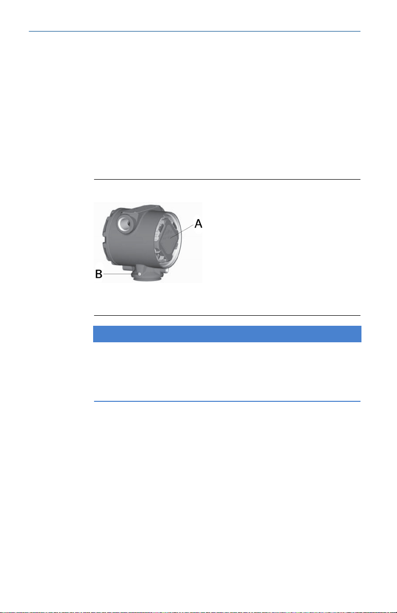
1. Loosen the housing rotation set screw.
2. Turn the housing up to 180° left or right of its original (as
shipped) position.
3. Re-tighten the housing rotation set screw.
Figure 2-1: Transmitter housing set screw
A. LCD display
B. Housing rotation set screw (3/32 in.)
NOTICE
Over-rotation may sever the electrical connection between the
sensor module and the electronics. Do not rotate the housing
more than 180° without first performing a disassembly
procedure.
12 www.Emerson.com
Page 13
November2024 Quick Start Guide
3 Set switches and jumpers
If alarm and security adjustment option is not installed, the
transmitter will operate normally with the default alarm condition
alarm High and the security Off.
Procedure
1. If the transmitters are live, set the loop to Manual and remove
power.
CAUTION
Do not remove the transmitter covers in explosive
atmospheres when the circuit is live.
2. Remove the electronics compartment cover.
CAUTION
Do not remove the housing cover in explosive environments.
Note
On:
• Junction box housing, remove the terminal block cover
• Plantweb™ housing, the cover is opposite the field
terminals side
3. To set the security and alarm on:
• Junction box housing, pull the pins out and rotate 90° into
desired position.
• Plantweb housing, slide the security and alarm switches
into the preferred position by using a small screwdriver.
Note
An LCD display or an adjustment module must be in place
to activate the switches.
4. To meet explosion-proof requirements, reinstall the housing
cover so metal contacts metal.
www.Emerson.com 13
Page 14
A
B
C
Quick Start Guide November2024
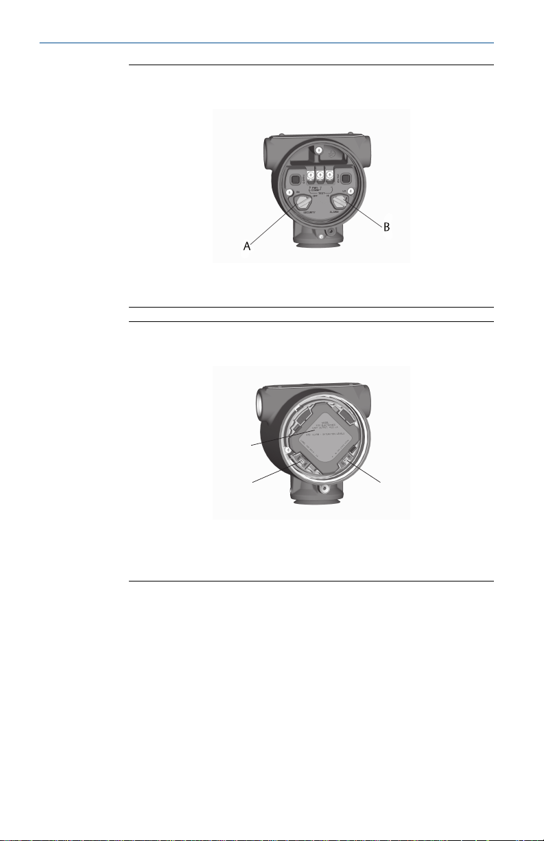
Figure 3-1: Transmitter Switch and Jumper Configuration
(Junction Box)
A. Security
B. Alarm
Figure 3-2: Transmitter Switch and Jumper Configuration
(Plantweb)
A. Meter/adjustment module
B. Security
C. Alarm
14 www.Emerson.com
Page 15
FIELDBUS WIRING
DP
A
D
E
B
C
November2024 Quick Start Guide
4 Connect wiring and power up
Prerequisites
The transmitter requires 9-32 Vdc to operate. Type A FOUNDATION
Fieldbus wiring 18 AWG twisted shielded pair is recommended.
Procedure
1. Remove and discard orange conduit plugs.
2. Remove the housing cover labeled Field Terminals.
Note
Do not connect the power across the test terminals. Power
could damage the test diode in the test connection. Twisted
pairs yield best results. Use 24–14 AWG wire and do not
exceed 5,000 ft. (1,500m). For single compartment housing
(Junction Box housing), shielded signal wiring should be used
in high EMI/RFI environments.
3. Connect the positive lead to the + terminal, and the negative
lead to the – terminal.
4. Connect the power leads to the terminals indicated on the
terminal block.
™
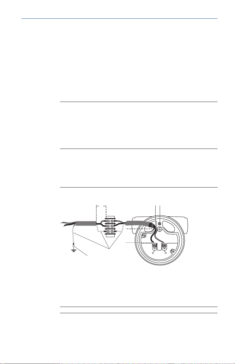
Figure 4-1: Transmitter wiring
A. Minimize distance
B. Trim shield and insulate
C. Ground for transient protection
D. Insulate shield
E. Connect shield back to power supply ground
Note
The device power terminals are polarity insensitive, which
means the electrical polarity of the power leads does
www.Emerson.com 15
Page 16
A
B
Quick Start Guide November2024
not matter when connecting to the power terminals. If
polarity sensitive devices are connected to the segment,
follow terminal polarity. When wiring to the screw terminals,
Emerson recommends using crimped legs.
5. Plug and seal the unused conduit connection with the
provided conduit plug.
NOTICE
When the enclosed threaded plug is utilized in the conduit
opening, it must be installed with a minimum thread
engagement in order to comply with explosion-proof
requirements.
• For straight threads, a minimum of seven threads must be
engaged.
• For tapered threads, a minimum of five threads must be
engaged.
6. If applicable, install wiring with a drip loop. Arrange the drip
loop sothe bottom is lower than the conduit connections and
the transmitterhousing.
7. Reinstall the housing cover and tighten so the cover is fully
seated with metal to metal contact between the housing and
cover in order to meet explosion-proof requirements.
The following figures show the wiring connections necessary
to power a transmitter and enable communications with a
handheld Field Communicator.
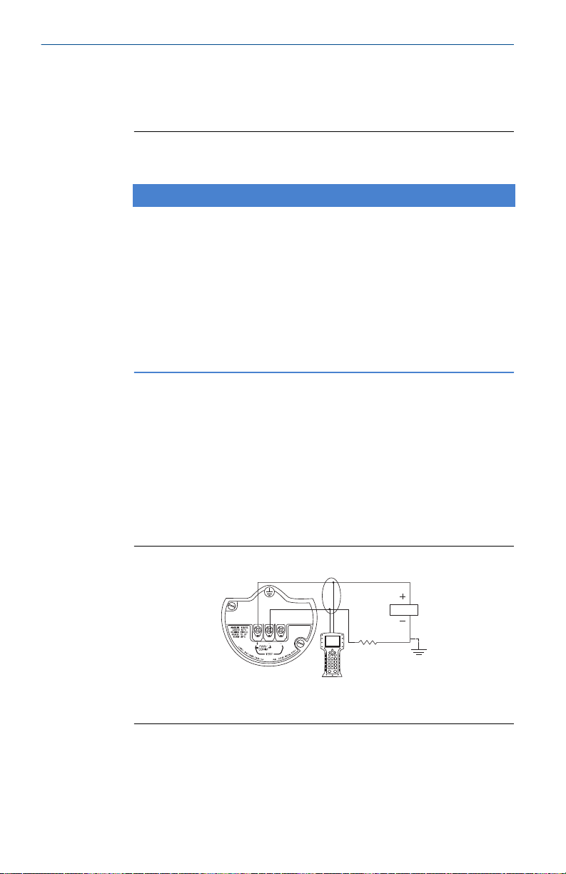
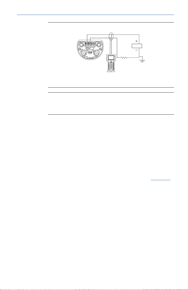
Figure 4-2: Transmitter Wiring for Plantweb Housing
A. RL ≥ 250 Ω
B. Power supply
16 www.Emerson.com
Page 17
A
B
November2024 Quick Start Guide
Figure 4-3: Transmitter Wiring for Junction Box Housing
A. RL ≥ 250 Ω
B. Power supply
Note
Installation of the transient protection terminal block does not
provide transient protection unless the Rosemount 3051S case
is properly grounded.
4.1 Ground signal wiring
Do not run signal wiring in conduit or open trays with power
wiring, or near heavy electrical equipment. Grounding terminations
are provided on the sensor module and inside the terminal
compartment. These grounds are used when transient protection
terminal blocks are installed or to fulfill local regulations.
Procedure
1. Remove the Field Terminals housing cover.
2. Connect the wiring pair and ground as indicated in
Figure 4-4.
The cable shield should:
• Be trimmed close and insulated from touching the
transmitter housing
• Continuously connect to the termination point
• Be connected to a good earth ground at the power supply
end
www.Emerson.com 17
Page 18

DP
C
A
B
B
D
E
Quick Start Guide November2024
Figure 4-4: Wiring
A. Insulate shield
B. Minimize distance
C. Connect shield back to the power supply ground
D. Trim shield and insulate
E. Safety ground
3. Connect the wiring pair and ground as indicated in Figure 4-1.
The cable shield should:
• Be trimmed close and insulated from touching the
transmitter housing
• Continuously connect to the termination point
• Be connected to a good earth ground at the power supply
end
4. Replace the housing cover.
Note
Emerson recommends tightening the cover until no gap is
present between the cover and the housing.
5. Plug and seal the unused conduit connection with the
provided conduit plug.
4.2
Remote display wiring and power up (if applicable)
The remote mount display and Interface system consists of a local
transmitter and a remote mount LCD display assembly. The local
Rosemount 3051S assembly includes a Junction Box housing with
a three-position terminal block integrally mounted to a sensor
module. The remote mount LCD display assembly consists of a dual
compartment Plantweb housing with a seven position terminal block.
Figure 4-5 for complete wiring instructions. The following is a
See
list of necessary information specific to the remote mount display
system:
18 www.Emerson.com
• Each terminal block is unique for the remote display system.
Page 19

November2024 Quick Start Guide
• A 316 SST housing adaptor is permanently secured to the remote
mount LCD display Plantweb housing, providing an external
ground and a means for field mounting with the provided
mounting bracket.
• A cable is required for wiring between the transmitter and remote
mount LCD display. The cable length is limited to 100 ft.
• 50 ft. (option M8) or 100 ft. (option M9) cable is provided
for wiring between the transmitter and remote mount LCD
display. Option M7 does not include cable; see the following
recommended specifications:
—
Cable type
— Cable length
Cable capacitance
—
— Intrinsic safety consideration
Cable type
Emerson recommends Madison AWM Style 2549 cable. Other
comparable cable may be used if it has independent dual twisted
shielded pair wires with an outer shield. The power wires must be 22
AWG minimum and the CAN communication wires must be 24 AWG
minimum.
Cable length
The cable length is up to 100 ft., depending upon cable capacitance.
Cable capacitance
The capacitance from the CAN communications line to the CAN
return line as wired must be less than 5,000 picofarads total. This
allows up to 50 picofarads per foot for a 100-foot cable.
Intrinsic safety consideration
The transmitter assembly with remote display has been approved
with Madison AWM Style 2549 cable. Alternate cable may be used as
long as the transmitter with remote display and cable is configured
according to the installation control drawing or certificate. Refer to
appropriate approval certificate or control drawing in AppendixB
of the Rosemount 3051S Reference Manual for remote cable IS
requirements.
www.Emerson.com 19
Page 20
Quick Start Guide November2024
CAUTION
Do not apply power to the remote communications terminal. Follow
wiring instructions carefully to prevent damage to system
components.
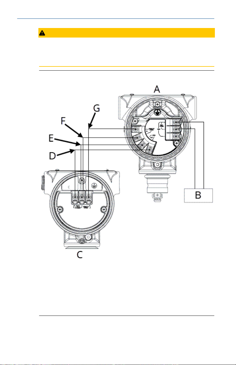
Figure 4-5: Remote Mount Display Wiring Diagram
A. Remote mount display
B. 4–20 mA
C. Junction box housing
D. Red: 22 AWG
E. Black: 22 AWG
F. Blue: 24AWG
G. White: 24AWG
20 www.Emerson.com
Page 21
A
B
D
E
F
C
November2024 Quick Start Guide
Note
Wire colors provided are per Madison AWM Style 2549 cable. Wire
color may vary depending on cable selected.
Madison AWM Style 2549 cable includes a ground shield. This shield
must be connected to earth ground at either the sensor module or
the remote display, but not both.
4.3 Quick connect wiring (if applicable)
As standard, the Rosemount 3051S Quick Connect arrives properly
assembled to the sensor module and is ready for installation.
Cordsets and field wireable connectors (in shaded area) are sold
separately.
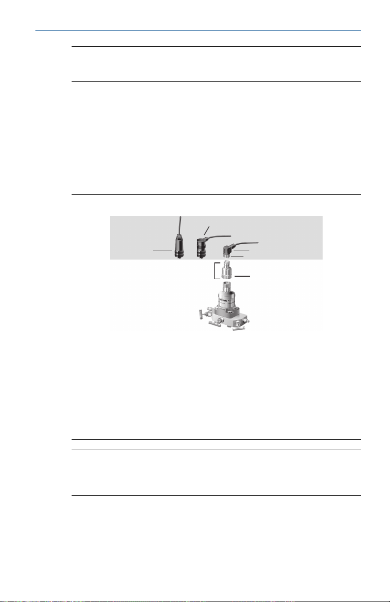
Figure 4-6: Rosemount 3051S Quick Connect Exploded View
A. Straight field wireable connector (part number
03151-9063-0001), supplied by customer
B. Right angle field wireable connector (part number
03151-9063-0002), supplied by customer
C. Quick Connect housing
D. Cordset, supplied by vendor
E. Coupling nut
F. Quick Connect coupling nut
Note
If Quick Connect is ordered as a Rosemount 300S spare housing or
is removed from the sensor module, follow the instructions below for
proper assembly prior to field wiring.
Procedure
www.Emerson.com 21
1. Place the Quick Connect onto the sensor module. To ensure
proper pin alignment, remove coupling nut prior to installing
quick connect onto the sensor module.
Page 22

A
B
“+”
“-”
Quick Start Guide November2024
2. Place coupling nut over quick connect and wrench tighten to a
maximum of 300 in-lb (34 N-m).
3. Tighten the set screw up to 30 in-lb using a 3/32-in. hex
wrench.
4. Install cordset/field wireable connectors onto the Quick
Connect. Do not over tighten.
Figure 4-7: Quick Connect HousingPin-Out
A. Ground
B. No connection
Note
For other wiring details, refer to pin-out drawing and the
cordset manufacturer’s installation instructions.
4.4 Conduit electrical connector wiring (option GE or GM)
For Rosemount 3051S with conduit electrical connectors GE or
GM, refer to the cordset manufacturer’s installation instructions
for wiring details. For FM Intrinsically Safe, non-incendive, or FM
FISCO Intrinsically Safe hazardous locations, install in accordance
with Rosemount drawing 03151-1009.
Additional information can be found in the Rosemount 3051S
Reference Manual.
4.5
22 www.Emerson.com
Power supply
The DC power supply should provide power with less than two
percent ripple. The total resistance load is the sum of the resistance
of the signal leads and the load resistance of the
• Controller
• Indicator
• Related pieces
Page 23

1387
1000
500
0
10.5 20 30
42.4
Voltage (Vdc)
Load (Ohms)
Operating
Region
November2024 Quick Start Guide
Note
If intrinsic safety barriers are used, their resistance must be included.
Figure 4-8: Load Limitation
Maximum loop resistance = 43.5 x (power supply voltage – 10.5)
NOTICE
The Field Communicator requires a minimum loop resistance of 250Ω
for communication.
The transmitter requires between 9 and 32 Vdc to operate and
provide complete functionality.
www.Emerson.com 23
Page 24
SAVE
3051:PT 93207
Online
1 Device setup
2 PV 0.00 mbar
3 Analog Output 4.000 mA
4 PV LRV 0.00 mbar
5 PV URV 370.00 mbar
SAVE
3051:PT 93207
Online
1 Overview
2 Configure
3 Service Tools
Quick Start Guide November2024
5 Verify configuration
Use any HART-compliant master to communicate with and verify
configuration of the Rosemount 3051S.
Field Communicator user interface
Fast Key sequences vary with the device driver revision. Reference
Table 5-1 for DD Rev. 8 or older. Reference Table 5-2 for DD Rev. 9 or
newer.
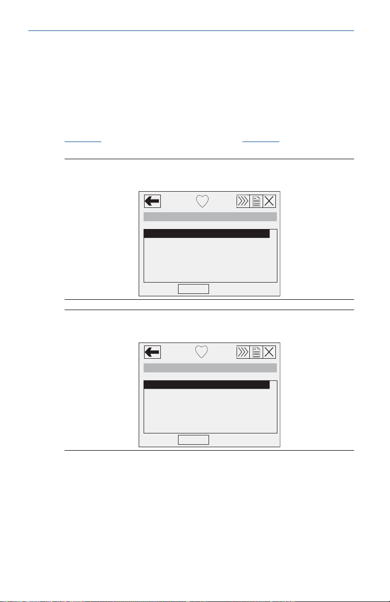
Figure 5-1: Traditional Interface - Device Revision 6 or 7 and DD
Revision 7
Figure 5-2: Device Dashboard - Device Revision 7 and DD Revision
9
A check (✓) indicates the basic configuration parameters. At a
minimum, these parameters should be verified as part of the
configuration and startup procedure.
24 www.Emerson.com
Page 25

November2024 Quick Start Guide
Table 5-1: Fast Key Sequences-Traditional Interface (Device
Revision 6 or 7 and DD Revision 7)
Function Fast Key sequence
Alarm Level
Configuration
Alarm and Saturation
Levels
Analog Output Alarm
Direction
Analog Output Trim 1, 2, 3, 2
Burst Mode On/Off 1, 4, 3, 3, 3
Burst Options 1, 4, 3, 3, 4
✓ Damping 1, 3, 6
Date 1, 3, 4, 1
Descriptor 1, 3, 4, 2
Digital To Analog Trim
(4–20 mA Output)
Field Device
Information
LCD Display
Configuration
Loop Test 1, 2, 2
Lower Sensor Trim 1, 2, 3, 3, 2
Message 1, 3, 4, 3
Number of Requested
Preambles
Pressure Alert
Configuration
Poll Address 1, 4, 3, 3, 1
Poll a Multidropped
Transmitter
Remapping 1, 4, 3, 6
Rerange- Keypad Input 1, 2, 3, 1, 1
Saturation Level
Configuration
1, 4, 2, 7, 7
1, 4, 2, 7
1, 4, 2, 7, 6
1, 2, 3, 2, 1
1, 4, 4, 1
1, 3, 7
1, 4, 3, 3, 2
1, 4, 3, 5, 3
Left Arrow, 3, 1, 1
1, 4, 2, 7, 8
www.Emerson.com 25
Page 26
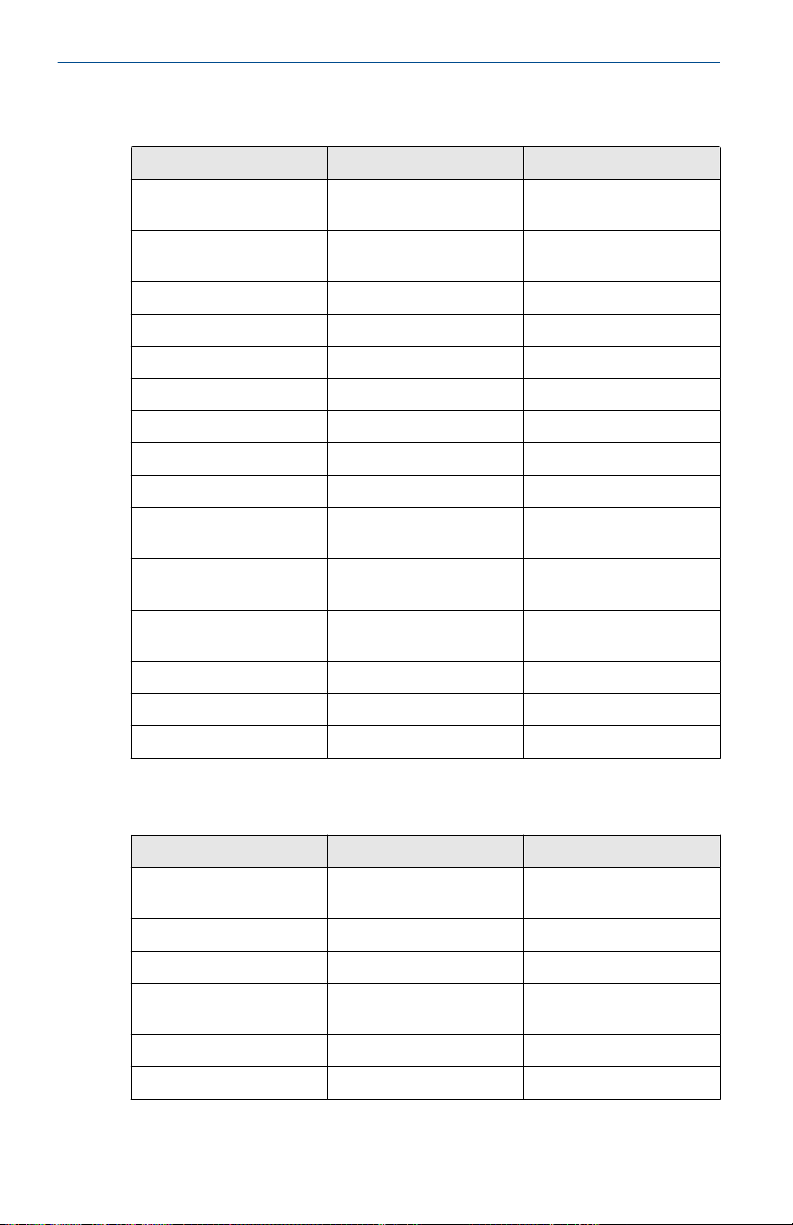
Quick Start Guide November2024
Table 5-1: Fast Key Sequences-Traditional Interface (Device
Revision 6 or 7 and DD Revision 7)
Function Fast Key sequence
Scaled D/A Trim (4–20
mA Output)
Scaled Variable
Configuration
Self Test (Transmitter) 1, 2, 1, 1
Sensor Information 1, 4, 4, 2
Sensor Temperature 1, 1, 4
Sensor Trim 1, 2, 3, 3
Sensor Trim Points 1, 2, 3, 3, 5
Status 1, 2, 1, 2
✓ Tag 1, 3, 1
Temperature Alert
Configuration
✓ Transfer Function
(Setting Output Type)
Transmitter Security
(Write Protect)
✓ Units (Process Variable) 1, 3, 2
Upper Sensor Trim 1, 2, 3, 3, 3
Zero Trim 1, 2, 3, 3, 1
(continued)
1, 2, 3, 2, 2
1, 4, 3, 4, 7
1, 4, 3, 5, 4
1, 3, 5
1, 3, 4, 5
Table 5-2: Fast Key Sequences-Device Dashboard (Device Revision
7 and DD Revision 9)
Function Fast Key sequence
Alarm and Saturation
Levels
Burst Mode Control 2, 2, 4, 2
Burst Option 2, 2, 4, 3
Custom Display
Configuration
✓ Damping 2, 2, 1, 5
Date 2, 2, 5, 4
26 www.Emerson.com
2, 2, 1, 7
2, 1, 3
Page 27

November2024 Quick Start Guide
Table 5-2: Fast Key Sequences-Device Dashboard (Device Revision
7 and DD Revision 9)
Function Fast Key sequence
Descriptor 2, 2, 5, 5
Digital to Analog Trim
Disable Zero & Span
Rerange with Keypad 2, 2, 1, 3, 1
Loop Test 3, 5, 1
Lower Sensor Trim 3, 4, 1, 2
Message 2, 2, 5, 6
Range Values 2, 2, 1, 3
Scaled D/A Trim (4–20
Sensor Temperature/
✓ Tag 2, 2, 5, 1
✓ Transfer Function 2, 2, 1, 4
Transmitter Security
✓ Units 2, 2, 1, 2
Upper Sensor Trim 3, 4, 1, 1
Zero Trim 3, 4, 1, 3
(continued)
3, 4, 2
(4–20 mA Output)
2, 2, 7, 2
Adjustment
3, 4, 2
mA Output)
3, 3, 3
Trend (3051S)
2, 2, 7, 1
(Write Protect)
www.Emerson.com 27
Page 28

Quick Start Guide November2024
6 Trim the transmitter
Transmitters are shipped fully calibrated per request or by the
factory default of full scale (Lower Range Value = zero, Upper Range
Value = upper range limit).
6.1 Zero trim
Prerequisites
Choose your trim procedure
1. Analog zero trim - sets the analog output to 4 mA.
a. Also referred to as a "rerange", it sets the Lower Value
Range (LVR) equal to the measured pressure.
b. The display and digital HART output remains
unchanged.
2. Digital zero trim - recalibrates the sensor zero.
a. The LVR is unaffected. The pressure value will be zero
(on display and HART output). 4 mA point may not be at
zero.
b. The transmitter must be within 3 percent of URL from
factory calibrated zero pressure in order to calibrate the
zero function.
6.1.1 Use the Field Communicator
Procedure
1. Equalize or vent the transmitter and connect Field
Communicator.
2. At the menu, input the Fast Key sequence (refer to Field
Communicator user interface).
3. Follow the commands to perform a zero trim.
6.1.2 Use the transmitter zero adjustment button
Procedure
To perform an analog zero trim using the tansmitter buttons push
and hold the zero adjustment button for at least two seconds but no
longer than 10 seconds.
28 www.Emerson.com
Page 29
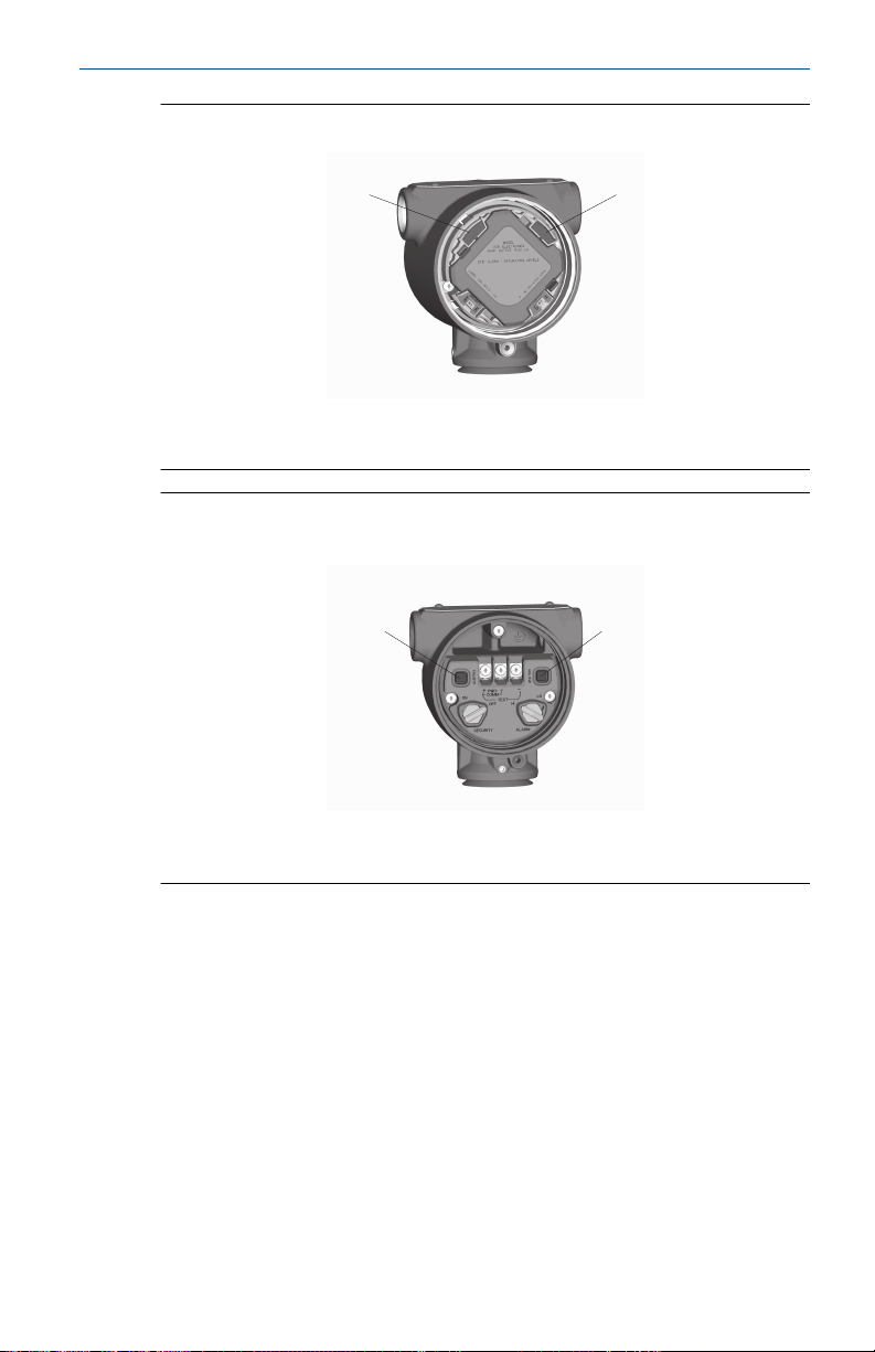
A
B
A B
November2024 Quick Start Guide
Figure 6-1: Transmitter Adjustment Buttons (Plantweb Housing)
A. Zero
B. Span
Figure 6-2: Transmitter Adjustment Buttons (Junction Box
Housing)
A. Zero
B. Span
www.Emerson.com 29
Page 30

Quick Start Guide November2024
7 Safety instrumented systems installation
For safety certified installations, refer to the Rosemount
3051S Reference Manual for installation procedure and system
requirements.
30 www.Emerson.com
Page 31

November2024 Quick Start Guide
8 Rosemount 3051S/3051SFx/3051S-ERS
Rev 3.14
European Directive Information
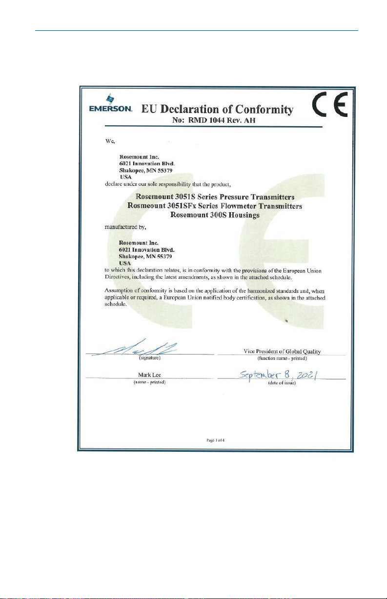
A copy of the EU Declaration of Conformity can be found at the
end of the Quick Start Guide. The most recent revision of the EU
Declaration of Conformity can be found at emerson.com/rosemount.
Ordinary Location Certification
As standard, the transmitter has been examined and tested to
determine that the design meets the basic electrical, mechanical,
and fire protection requirements by a nationally recognized test
laboratory (NRTL) as accredited by the Federal Occupational Safety
and Health Administration (OSHA).
Installing Equipment in North America
The US National Electrical Code (NEC) and the Canadian Electrical
Code (CEC) permit the use of Division marked equipment in Zones
and Zone marked equipment in Divisions. The markings must be
suitable for the area classification, gas, and temperature class. This
information is clearly defined in the respective codes.
8.1 USA
8.1.1 E5 US Explosionproof (XP) and Dust-Ignitionproof (DIP)
Certificate
Standards
Markings
8.1.2 I5 US Intrinsic Safety (IS) and Nonincendive (NI)
Certificate
Standards
Markings
www.Emerson.com 31
FM16US0090
FM Class 3600 – 2018, FM Class 3615 – 2018, FM Class
3616 – 2011, FM Class 3810 – 2018, ANSI/NEMA 250 –
2003
XP CL I, DIV 1, GP B, C, D; DIP CL II, DIV 1, GP E, F, G; CL
III; T5(-50 °C ≤ Ta ≤ +85 °C); Factory Sealed; Type 4X
FM16US0089X
FM Class 3600:2018, FM Class 3610:2010, FM Class
3611:2004, FM Class 3616:2011, FM Class 3810:2018,
ANSI/ISA-60079-0:2013, ANSI/ISA-60079-11:2013, ANSI/
ISA-61010-1:2004, NEMA 250:1991 (3051SFA only) or
NEMA 250:2003
IS CL I, DIV 1, GP A, B, C, D; CL II, DIV 1, GP E, F, G;
Class III; Class 1, Zone 0 AEx ia IIC T4; NI CL 1, DIV 2, GP
Page 32

Quick Start Guide November2024
A, B, C, D; T4(-50 °C ≤ Ta ≤ +70 °C) [HART]; T4(-50 °C ≤
Ta ≤ +60 °C) [Fieldbus]; when connected per Rosemount
drawing 03151-1006; Type 4X
Special Condition for Safe Use (X):
The Model 3051S/3051S-ERS Pressure Transmitter contains
aluminum and is considered to constitute a potential risk of ignition
by impact or friction. Care must be taken into account during
installation and use to prevent impact and friction.
Note
Transmitters marked with NI CL 1, DIV 2 can be installed in Division
2 locations using general Division 2 wiring methods or Nonincendive
Field Wiring (NIFW). See Drawing 03151-1006.
US Intrinsic Safety (IS) and Nonincendive (NI)
Certificate
Standards
Markings
8.1.3 IE US FISCO
Certificate
Standards
Markings
Special Condition for Safe Use (X):
The Model 3051S/3051S-ERS Pressure Transmitter contains
aluminum and is considered to constitute a potential risk of ignition
by impact or friction. Care must be taken into account during
installation and use to prevent impact and friction.
US FISCO
1143113
FM Class 3600:2011, FM Class 3610:2010, FM Class
3611:2004, FM Class 3810:2005, UL50E (1st Ed.)
IS Class I/II/III, Division 1, Groups A, B, C, D, T4/ E, F, and
G T135 °C;
Class I, Zone 0 AEx ia IIC T4 Ga;
T4(-50 °C ≤ Ta ≤ +70 °C) [HART];
T4(-50 °C ≤ Ta ≤ +60 °C) [Fieldbus];
when connected per Rosemount drawing 03151-1016;
Type 4X
FM16US0089X
FM Class 3600 – 2011, FM Class 3610 – 2010, FM Class
3611 – 2004, FM Class 3810 – 2005, NEMA 250 – 2003
IS CL I, DIV 1, GP A, B, C, D; T4(-50 °C ≤ Ta ≤ +60 °C); when
connected per Rosemount drawing 03151-1006; Type 4X
32 www.Emerson.com
Page 33

November2024 Quick Start Guide
Certificate
Standards
1143113
FM Class 3600:2011, FM Class 3610:2010, FM Class
3611:2004, FM Class 3810:2005, UL50E (1st Ed.)
Markings
IS Class I/II/III, Division 1, Groups A, B, C, D, T4/ E, F, and
G T135 °C;
Class I, Zone 0 AEx ia IIC T4 Ga;
T4(-50 °C ≤ Ta ≤ +70 °C) [HART];
T4(-50 °C ≤ Ta ≤ +60 °C) [Fieldbus];
when connected per Rosemount drawing 03151-1016;
Type 4X
8.2 Canada
8.2.1 E6 Canada Explosionproof, Dust-Ignitionproof, and Division 2
Certificate
Standards
Markings
1143113
CAN/CSA C22.2 No. 0-10, CSA Std C22.2 No. 25-1966,
CSA Std C22.2 No. 30-M1986, CAN/CSA C22.2 No. 94M91, CSA Std C22.2 No. 142-M1987, CSA Std C22.2 No.
213-M1987, ANSI/ISA 12.27.01-2003, CSA Std C22.2 No.
60529:05
Explosionproof Class I, Division 1, Groups B, C, D; DustIgnitionproof Class II, Division 1, Groups E, F, G; Class III;
suitable for Class I, Zone 1, Group IIB+H2, T5; suitable
for Class I, Division 2, Groups A, B, C, D; suitable for
Class I, Zone 2, Group IIC, T5; when connected per
Rosemount drawing 03151-1013; Type 4X
8.2.2 I6 Canada Intrinsically Safe
Certificate
Standards
Markings
1143113
CAN/CSA C22.2 No. 0-10, CSA Std C22.2 No. 30M1986, CAN/CSA C22.2 No. 94-M91, CSA Std C22.2
No. 142-M1987, CSA Std C22.2 No. 157-92, ANSI/ISA
12.27.01-2003, CSA Std C22.2 No. 60529:05
Intrinsically Safe Class I, Division 1; Groups A, B, C, D;
suitable for Class 1, Zone 0, IIC, T3C; when connected
per Rosemount drawing 03151-1016 [3051S] 03151-1313
[ERS]; Type 4X
8.2.3 IF Canada FISCO
Certificate
www.Emerson.com 33
1143113
Page 34
Quick Start Guide November2024
Standards
CAN/CSA C22.2 No. 0-10, CSA Std C22.2 No. 30M1986, CAN/CSA C22.2 No. 94-M91, CSA Std C22.2
No. 142-M1987, CSA Std C22.2 No. 157-92, ANSI/ISA
12.27.01-2003, CSA Std C22.2 No. 60529:05
Markings
FISCO Intrinsically Safe Class I, Division 1; Groups A, B, C,
D; suitable for Class 1, Zone 0, IIC, T3C; when connected
per Rosemount drawing 03151-1016 [3051S] 03151-1313
[ERS]; Type 4X
8.3 Europe
8.3.1 E1 ATEX Flameproof
Certificate
Standards
Markings
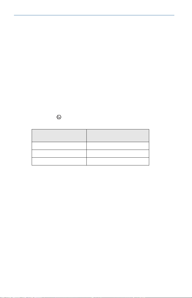
Temperature Class Process Connection
T6 –60 °C to +70 °C
T5 –60 °C to +80 °C
T4 –60 °C to +120 °C
KEMA 00ATEX2143X
EN IEC 60079-0:2018, EN 60079-1:2014, EN
60079-26:2015
II 1/2 G Ex db IIC T6…T4 Ga/Gb, T6(-60 °C ≤ Ta ≤
+70 °C), T5/T4(-60 °C ≤ Ta ≤ +80 °C)
Temperature
Special Conditions for Safe Use (X):
1. This device contains a thin wall diaphragm less than 1
mm thickness that forms a boundary between Category
1G (process connection) and Category 2G (all other parts
of the equipment). The model code and datasheet are
to be consulted for details of the diaphragm material.
During Installation, maintenance and use the environmental
conditions to which the diaphragm will be subjected shall
be taken into account. The manufacturer's instructions for
installation and maintenance shall be followed in detail to
assure safety during its expected lifetime.
2. Flameproof joints are not intended for repair.
3. Non-standard paint options may cause risk from electrostatic
discharge. Avoid installations that could cause electrostatic
build-up on painted surfaces, and only clean the painted
surfaces with a damp cloth. If paint is ordered through
34 www.Emerson.com
Page 35

November2024 Quick Start Guide
a special option code, contact the manufacturer for more
information.
4. Appropriate cable, glands and plugs need to be suitable
for a temperature of 5 °C greater than maximum specified
temperature for location where installed.
8.3.2 I1 ATEX Intrinsic Safety
Certificate
Standards
Markings
BAS01ATEX1303X
EN IEC 60079-0: 2018, EN 60079-11: 2012
II 1 G Ex ia IIC T4 Ga, T4(-60 °C ≤ Ta ≤ +70 °C)
Table 8-1: Input Parameters
Ui Ii Pi Ci Li
SuperModule 30 V 300 mA 1.0 W 30 nF 0
3051S...A; 3051SF…
A; 3051SAL…C
3051S…F; 3051SF…F 30 V 300 mA 1.3 W 0 0
3051S …A…M7, M8,
or M9; 3051SF …A…
M7, M8, or M9;
3051SAL…C… M7,
M8, or M9
3051SAL or
3051SAM
3051SAL…M7, M8,
or M9 3051SAM…
M7, M8, or M9
RTD Option for
3051SF
30 V 300 mA 1.0 W 12 nF 0
30 V 300 mA 1.0 W 12 nF 60 µH
30 V 300 mA 1.0 W 12 nF 33 µH
30 V 300 mA 1.0 W 12 nF 93 µH
5 V 500 mA 0.63 W N/A N/A
Special Conditions for Safe Use (X):
1. The Model 3051S Transmitters fitted with transient protection
are not capable of withstanding the 500V test as defined in
Clause 6.3.13 of EN 60079-11:2012. This must be taken into
account during installation.
2. The terminal pins of the Model 3051S SuperModule must
be provided with a degree of protection of at least IP20 in
accordance with IEC/EN 60529.
3. The Model 3051S enclosure may be made of aluminum alloy
and given a protective polyurethane paint finish; however,
www.Emerson.com 35
Page 36
Quick Start Guide November2024
care should be taken to protect it from impact or abrasion if
located in a zone 0 area.
8.3.3 IA ATEX FISCO
Certificate
Standards
Markings
BAS01ATEX1303X
EN IEC 60079-0: 2018, EN 60079-11: 2012
II 1 G Ex ia IIC T4 Ga, T4(-60 °C ≤ Ta ≤ +70 °C)
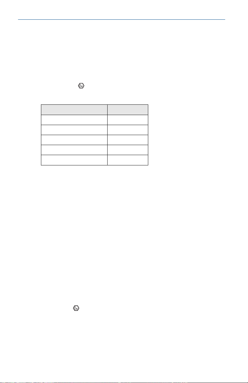
Table 8-2: Input Parameters
FISCO
Voltage U
Current I
Power P
Capacitance C
Inductance L
i
i
i
i
i
17.5 V
380 mA
5.32 W
0
0
Special Conditions for Safe Use (X):
1. The Model 3051S Transmitters fitted with transient protection
are not capable of withstanding the 500V test as defined in
Clause 6.3.13 of EN 60079-11:2012. This must be taken into
account during installation.
2. The terminal pins of the Model 3051S SuperModule must
be provided with a degree of protection of at least IP20 in
accordance with IEC/EN 60529.
3. The Model 3051S enclosure may be made of aluminum alloy
and given a protective polyurethane paint finish; however,
care should be taken to protect it from impact or abrasion if
located in a zone 0 area.
8.3.4 ND ATEX Dust
Certificate
Standards
Markings
Special Conditions for Safe Use (X):
1. Cable entries must be used which maintain the ingress
36 www.Emerson.com
BAS01ATEX1374X
EN 60079-0: 2012+A11:2013, EN 60079-31: 2009
II 1 D Ex ta IIIC T105 °C T
+85 °C), V
= 42.4 V
max
95 °C Da, (-20 °C ≤ Ta ≤
500
protection of the enclosure to at least IP66.
Page 37
November2024 Quick Start Guide
2. Unused cable entries must be filled with suitable blanking
plugs which maintain the ingress protection of the enclosure
to at least IP66.
3. Cable entries and blanking plugs must be suitable for the
ambient temperature range of the apparatus and capable of
withstanding a 7J impact test.
4. The SuperModule(s) must be securely screwed in place to
maintain the ingress protection of the enclosure(s).
8.3.5 N1 ATEX Type n
Certificate
Standards
Markings
BAS01ATEX3304X
EN IEC 60079-0: 2018, EN 60079-15: 2010
II 3 G Ex nA IIC T5 Gc, (-40 °C ≤ Ta ≤ +85 °C), V
45 V
Special Condition for Safe Use (X):
The equipment is not capable of withstanding the 500 V insulation
test required by clause 6.5 of EN 60079-15:2010. This must be taken
into account when installing the equipment.
Note
RTD Assembly is not included with the 3051SFx Type n Approval.
8.4
International
8.4.1 E7 IECEx Flameproof and Dust
Certificate
Standards
Markings
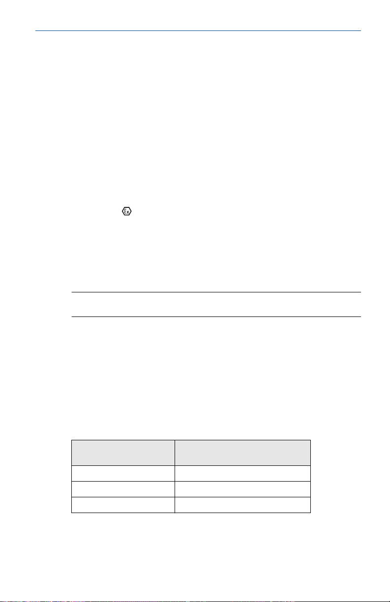
Table 8-3: Process Temperature
Temperature class Process Connection
T6 –60 °C to +70 °C
T5 –60 °C to +80 °C
T4 –60 °C to +120 °C
IECEx KEM 08.0010X (Flameproof)
IEC 60079-0:2017, IEC 60079-1:2014, IEC 60079-26:2014
Ex db IIC T6…T4 Ga/Gb, T6(-60 °C ≤ Ta ≤ +70 °C), T5/
T4(-60 °C ≤ Ta ≤ +80 °C)
Temperature
max
=
www.Emerson.com 37
Page 38

Quick Start Guide November2024
Special Conditions for Safe Use (X):
1. This device contains a thin wall diaphragm less than 1
mm thick that forms a boundary between EPL Ga (process
connection) and EPL Gb (all other parts of the equipment). The
model code and datasheet are to be consulted for details of
the diaphragm material. During installation, maintenance and
use the environmental conditions to which the diaphragm will
be subjected shall be taken into account. The manufacturer's
instructions for installation and maintenance shall be followed
in detail to assure safety during its expected lifetime.
2. Flameproof joints are not intended for repair.
3. Non-standard paint options may cause risk from electrostatic
discharge. Avoid installations that could cause electrostatic
build-up on painted surfaces, and only clean the painted
surfaces with a damp cloth. If paint is ordered through
a special option code, contact the manufacturer for more
information.
4. Appropriate cable, glands and plugs need to be suitable
for a temperature of 5 °C greater than maximum specified
temperature for location where installed.
Certificate
Standards IEC 60079-0:2011, IEC 60079-31:2008
Markings Ex ta IIIC T105 °C T
IECEx BAS 09.0014X (Dust)
95 °C Da, (-20 °C ≤ Ta ≤
+85 °C), V
max
500
= 42.4 V
Special Conditions for Safe Use (X):
1. Cable entries must be used which maintain the ingress
protection of the enclosure to at least IP66.
2. Unused cable entries must be filled with suitable blanking
plugs which maintain the ingress protection of the enclosure
to at least IP66.
3. Cable entries and blanking plugs must be suitable for the
ambient temperature range of the apparatus and capable of
withstanding a 7J impact test.
4. The 3051S- SuperModule must be securely screwed in place to
maintain the ingress protection of the enclosure.
8.4.2 I7 IECEx Intrinsic Safety
Certificate
38 www.Emerson.com
IECEx BAS 04.0017X
Page 39

November2024 Quick Start Guide
Standards
Markings
IEC 60079-0: 2017, IEC 60079-11: 2011
Ex ia IIC T4 Ga, T4(-60 °C ≤ Ta ≤ +70 °C)
Table 8-4: Input Parameters
Ui Ii Pi Ci Li
SuperModule 30 V 300 mA 1.0 W 30 nF 0
3051S...A; 3051SF…A;
3051SAL…C
3051S…F; 3051SF…F 30 V 300 mA 1.3 W 0 0
3051S …A…M7, M8,
or M9; 3051SF …A…
M7, M8, or M9;
3051SAL…C… M7,
M8, or M9
3051SAL or 3051SAM 30 V 300 mA 1.0 W 12 nF 33 µH
3051SAL…M7, M8, or
M9 3051SAM…M7,
M8, or M9
RTD Option for
3051SF
30 V 300 mA 1.0 W 12 nF 0
30 V 300 mA 1.0 W 12 nF 60 µH
30 V 300 mA 1.0 W 12 nF 93 µH
5 V 500 mA 0.63 W N/A N/A
Special Conditions for Safe Use (X):
1. The Model 3051S Transmitters fitted with transient protection
are not capable of withstanding the 500 V test as defined in
Clause 6.3.13 of EN 60079-11:2012. This must be taken into
account during installation.
2. The terminal pins of the Model 3051S SuperModule must
be provided with a degree of protection of at least IP20 in
accordance with IEC/EN 60529.
3. The Model 3051S enclosure may be made of aluminum alloy
and given a protective polyurethane paint finish; however,
care should be taken to protect it from impact or abrasion if
located in a zone 0 area.
8.4.3 I7 IECEx Intrinsic Safety – Group I - Mining (I7 with Special A0259)
Certificate
Standards
Markings
www.Emerson.com 39
IECEx TSA 14.0019X
IEC 60079-0: 2011, IEC 60079-11: 2011
Ex ia I Ma (-60 °C ≤ Ta ≤ +70 °C)
Page 40

Quick Start Guide November2024
Table 8-5: Input Parameters
Ui Ii Pi Ci Li
SuperModule 30 V 300 mA 1.0 W 30 nF 0
3051S...A; 3051SF…A;
3051SAL…C
3051S…F; 3051SF…F 30 V 300 mA 1.3 W 0 0
3051S …A…M7, M8,
or M9; 3051SF …A…
M7, M8, or M9;
3051SAL…C… M7,
M8, or M9
3051SAL or 3051SAM 30 V 300 mA 1.0 W 12 nF 33 µH
3051SAL…M7, M8, or
M9 3051SAM…M7,
M8, or M9
RTD Option for
3051SF
30 V 300 mA 1.0 W 12 nF 0
30 V 300 mA 1.0 W 12 nF 60 µH
30 V 300 mA 1.0 W 12 nF 93 µH
5 V 500 mA 0.63 W N/A N/A
Special Conditions for Safe Use (X):
1. If the apparatus is fitted with optional 90V transient
suppressor, it is not capable of withstanding the 500 V
insulation test required by Clause 6.3.13 of IEC60079-11. This
must be taken into account when installing the apparatus.
2. It is a condition of safe use that the above input parameters
shall be taken into account during installation.
3. It is a condition of manufacture that only the apparatus fitted
with housing, covers and sensor module housing made out of
stainless steel are used in Group I applications.
8.4.4 IG IECEx FISCO
Certificate
Standards
Markings
Table 8-6: Input Parameters
Parameter FISCO
Voltage U
Current I
40 www.Emerson.com
i
IECEx BAS 04.0017X
IEC 60079-0: 2017, IEC 60079-11: 2011
Ex ia IIC T4 Ga, T4(-60 °C ≤ Ta ≤ +70 °C)
i
17.5 V
380 mA
Page 41

November2024 Quick Start Guide
Table 8-6: Input Parameters
(continued)
Parameter FISCO
Power P
Capacitance C
Inductance L
i
i
i
5.32 W
0
0
Special Conditions for Safe Use (X):
1. The Model 3051S Transmitters fitted with transient protection
are not capable of withstanding the 500 V test as defined in
Clause 6.3.13 of EN 60079-11:2012. This must be taken into
account during installation.
2. The terminal pins of the Model 3051S SuperModule must
be provided with a degree of protection of at least IP20 in
accordance with IEC/EN 60529.
3. The Model 3051S enclosure may be made of aluminum alloy
and given a protective polyurethane paint finish; however,
care should be taken to protect it from impact or abrasion if
located in a zone 0 area.
8.4.5 IG IECEx Intrinsic Safety – Group I – Mining (IG with Special A0259)
Certificate
Standards
Markings
IECEx TSA 14.0019X
IEC 60079-0: 2011, IEC 60079-11: 2011
FISCO FIELD DEVICE Ex ia I Ma , (-60 °C ≤ Ta ≤ +70 °C)
Table 8-7: Input Parameters
Parameter FISCO
Voltage U
Current I
Power P
Capacitance C
Inductance L
i
i
i
i
i
17.5 V
380 mA
5.32 W
0
0
Special Conditions for Safe Use (X):
1. If the apparatus is fitted with optional 90V transient
suppressor, it is not capable of withstanding the 500 V
www.Emerson.com 41
Page 42

Quick Start Guide November2024
insulation test required by Clause 6.3.13 of IEC60079-11. This
must be taken into account when installing the apparatus.
2. It is a condition of safe use that the above input parameters
shall be taken into account during installation.
3. It is a condition of manufacture that only the apparatus fitted
with housing, covers and sensor module housing made out of
stainless steel are used in Group I applications.
8.4.6 N7 IECEx Type n
Certificate
Standards
Markings
IECEx BAS 04.0018X
IEC 60079-0: 2017, IEC 60079-15: 2010
Ex nA IIC T5 Gc, (-40 °C ≤ Ta ≤ +85 °C)
Special Condition for Safe Use (X):
1. The equipment is not capable of withstanding the 500 V insulation
test required by clause 6.5 of EN 60079-15:2010. This must be taken
into account when installing the equipment.
8.5 Brazil
8.5.1 E2 Brazil Flameproof
Certificate
Standards
Markings
Temperature Class Ambient Temperature Process Connection
T6 -60 °C to +70 °C -60 °C to +70 °C
T5 -60 °C to +80 °C -60 °C to +80 °C
T4 -60 °C to +80 °C -60 °C to +120 °C
UL-BR 15.0393X
ABNT NBR IEC 60079-0:2013, ABNT NBR IEC
60079-1:2016, ABNT NBR IEC 60079-26:2016
Ex db IIC T6...T4 Ga/Gb, T6 (–60 °C ≤ Ta ≤ +70 °C), T5/T4
(–60 °C ≤ Ta ≤ +80 °C), IP66
Temperature
Special Conditions for Safe Use (X):
1. The device contains a thin wall diaphragm less than 1mm thick
that forms a boundary between EPL Ga (process connection)
and EPL Gb (all other parts of the equipment). The model
code and datasheet are to be consulted for details of the
diaphragm material. Installation, maintenance, and use shall
take into account the environmental conditions to which the
42 www.Emerson.com
Page 43

November2024 Quick Start Guide
diaphragm will be subjected. The manufacturer’s instructions
for maintenance shall be followed in detail to assure safety
during its expected lifetime.
2. Flameproof joints are not intended for repair.
3. Non-standard paint options may cause risk from electrostatic
discharge. Avoid installations that could cause electrostatic
build-up on painted surfaces, and only clean the painted
surfaces with a damp cloth. If paint is ordered through
a special option code, contact the manufacturer for more
information.
8.5.2 I2/IB Brazil Intrinsic Safety/FISCO
Certificate
Standards
UL-BR 15.0392X
ABNT NBR IEC 60079-0:2013, ABNT NBR IEC
60079-11:2013
Markings
Ex ia IIC T4 Ga (–60 °C ≤ Ta ≤ +70 °C), IP66
Special Conditions for Safe Use (X):
1. The surface resistivity of the antenna is greater than 1 GΩ. To
avoid electrostatic charge build-up, it must not be rubbed or
cleaned with solvents or a dry cloth.
2. The Model 701PBKKF Power Module may be replaced in a
hazardous area. The Power Module has a surface resistivity
greater than 1 GΩ and must be properly installed in
the wireless device enclosure. Care must be taken during
transportation to and from the point of installation to prevent
electrostatic charge build-up.
3. The 3051S enclosure may be made of aluminium alloy and
given a protective polyurethane paint finish; however, care
must be taken to protect it from impact or abrasion if located
in areas that requires EPL Ga.
Table 8-8: Input Parameters
U
SuperModule 30 V 300 mA 1.0 W 30 nF 0
3051S...A; 3051SF…
A; 3051SAL…C
3051S…F; 3051SF…F 30 V 300 mA 1.3 W 0 0
3051S…F…IB;
3051SF…F…IB
i
30 V 300 mA 1.0 W 12 nF 0
17.5 V 380 mA 5.32 W 0 0
I
i
P
i
C
i
L
i
www.Emerson.com 43
Page 44

Quick Start Guide November2024
Table 8-8: Input Parameters
U
3051S …A…M7, M8,
or M9; 3051SF …A…
M7, M8, or M9;
3051SAL…C… M7,
M8, or M9
3051SAL or
3051SAM
3051SAL… M7, M8,
or M9 3051SAM…
M7, M8, or M9
RTD Option for
3051SF
i
30 V 300 mA 1.0 W 12 nF 60 µH
30 V 300 mA 1.0 W 12 nF 33 µH
30 V 300 mA 1.0 W 12 nF 93 µH
5 V 500 mA 0.63 W N/A N/A
(continued)
I
i
P
i
8.6 China
8.6.1 E3 China Flameproof and Dust Ignition-proof
Certificate
Standards
Markings
3051S: GYJ21.1120X
3051SFx: GYJ21.3300X
3051S-ERS: GYJ20.1489X
3051S: GB3836.1-2010, GB3836.2-2010, GB3836.20-2010,
GB12476.1-2013, GB12476.5-2013
3051SFx: GB3836.1-2010, GB3836.2-2010,
GB12476.1-2013, GB 12476.5-2013
3051S-ERS: GB3836.1-2010, GB3836.2-2010,
GB3836.20-2010
3051S: Ex d IIC T6…T4; Ex tD A20 T105 °C T
3051SFx: Ex d IIC T4~T6 Ga/Gb; Ex tD A20 IP66 T105 °C
T
95 °C; IP66
500
3051S-ERS: Ex d IIC T4~T6 Ga/Gb
C
i
L
95 °C; IP66
500
i
产品安全使用特殊条件
• 证书编号后缀 “X” 表明产品具有安全使用特殊条件: 涉及隔爆接合面的
维修须联系产品制造商.
• 产品使用注意事项
1. 用于爆炸性气体环境中, 产品使用环境温度与温度组别和介质温
度的关系为:
44 www.Emerson.com
Page 45

November2024 Quick Start Guide
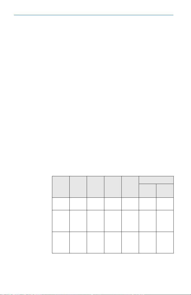
温度组别 环境温度 过程温度
T6 –60 °C ≤ Ta ≤ +70 °C –60 °C ≤ Ta ≤ +70 °C
T5 –60 °C ≤ Ta ≤ +80 °C –60 °C ≤ Ta ≤ +80 °C
T4 –60 °C ≤ Ta ≤ +80 °C –60 °C ≤ Ta ≤ +120
°C
2. 用于爆炸性粉尘环境中, 产品使用环境温度为: –20 °C ≤ Ta ≤
+85 °C.
3. 产品外壳设有接地端子, 用户在使用时应可靠接地.
4. 安装现场应不存在对产品外壳有腐蚀作用的有害气体.
5. 现场安装时, 电缆引入口须选用国家指定的防爆检验机构按检验
认可, 具有 Ex dⅡC, Ex tD A20 IP66 防爆等级的电缆引入装置或
堵封件, 冗余电缆引入口须用堵封件有效密封.
6. 用于爆炸性气体环境中, 现场安装, 使用和维护必须严格遵守 “断
电后开盖!” 的警告语. 用于爆炸性粉尘环境中, 现场安装, 使用和
维护必须严格遵守 “爆炸性粉尘场所严禁开盖!” 的警告语.
7. 用于爆炸性粉尘环境中, 产品外壳表面需保持清洁, 以防粉尘堆
积, 但严禁用压缩空气吹扫.
8. 用户不得自行更换该产品的零部件, 应会同产品制造商共同解决
运行中出现的故障, 以杜绝损坏现象的发生.
9. 产品的安装, 使用和维护应同时遵守产品使用说明书,
GB3836.13-2013 “爆炸性环境 第 13 部分: 设备的修理, 检修, 修
复和改造”, GB3836.15-2000 “爆炸性气体环境用电气设备 第 15
部分: 危险场所电气安装(煤矿除外)”, GB3836.16-2006 “爆炸
性气体环境用电气设备 第 16 部分: 电气装置的检查和维护(煤
矿除外)”, GB50257-2014 “电气装置安装工程爆炸和火灾危险
环境电力装置施工及验收规范” 和 GB15577-2007 “粉尘防爆安
全规程”, GB12476.2-2010 “可燃性粉尘环境用电气设备 第 2 部
分: 选型和安装”的有关规定.
8.6.2 I3 China Intrinsic Safety
Certificate
Standards
www.Emerson.com 45
3051S: GYJ21.1121X [Mfg USA, China, Singapore]
3051SFx: GYJ21.3301X [Mfg USA, China, Singapore]
3051S-ERS: GYJ21.1122X [Mfg USA, China, Singapore]
3051S: GB3836.1-2010, GB3836.4-2010, GB3836.20-2010
3051SFx: GB3836.1-2010, GB3836.4-2010,
GB3836.20-2010
Page 46
Quick Start Guide November2024
3051S-ERS: GB3836.1-2010, GB3836.4-2010,
GB3836.20-2010
Markings
3051S : Ex ia IIC T4 Ga
3051SF: Ex ia IIC T4 Ga
3051S-ERS: Ex ia IIC T4 G
产品安全使用特殊条件:
• 证书编号后缀 “X” 表明产品具有安全使用特殊条件:
1. 产品外壳含有轻金属, 用于 0 区时需注意防止由于冲击或摩擦产
生的点燃危险.
2. 当选择 T1 瞬态抑制端子时, 此设备不能承受 GB3836.4-2010 标
准中第 6.3.12 条规定的 500 V 交流有效值试验电压的介电强度
试验.
3. Transmitter output 为 X 时, 天线表面电阻大于 1 GΩ, 为了避免
静电积聚, 不允许用溶剂或者干布擦拭; 电源模块表面电阻大于
1 GΩ, 如果在危险区域更换, 则需要避免静电积聚; 只能使用由原
制造厂提供的 P/N 753-9220-XXXX 电池.
• 产品使用注意事项:
1. 产品使用环境温度为:
用于爆炸性气体环境中, 产品使用环境温度为: – 60 °C ≤ Ta ≤
+70 °C
用于爆炸性粉尘环境中, 产品使用环境温度为: – 20 °C ≤ Ta ≤
+85 °C
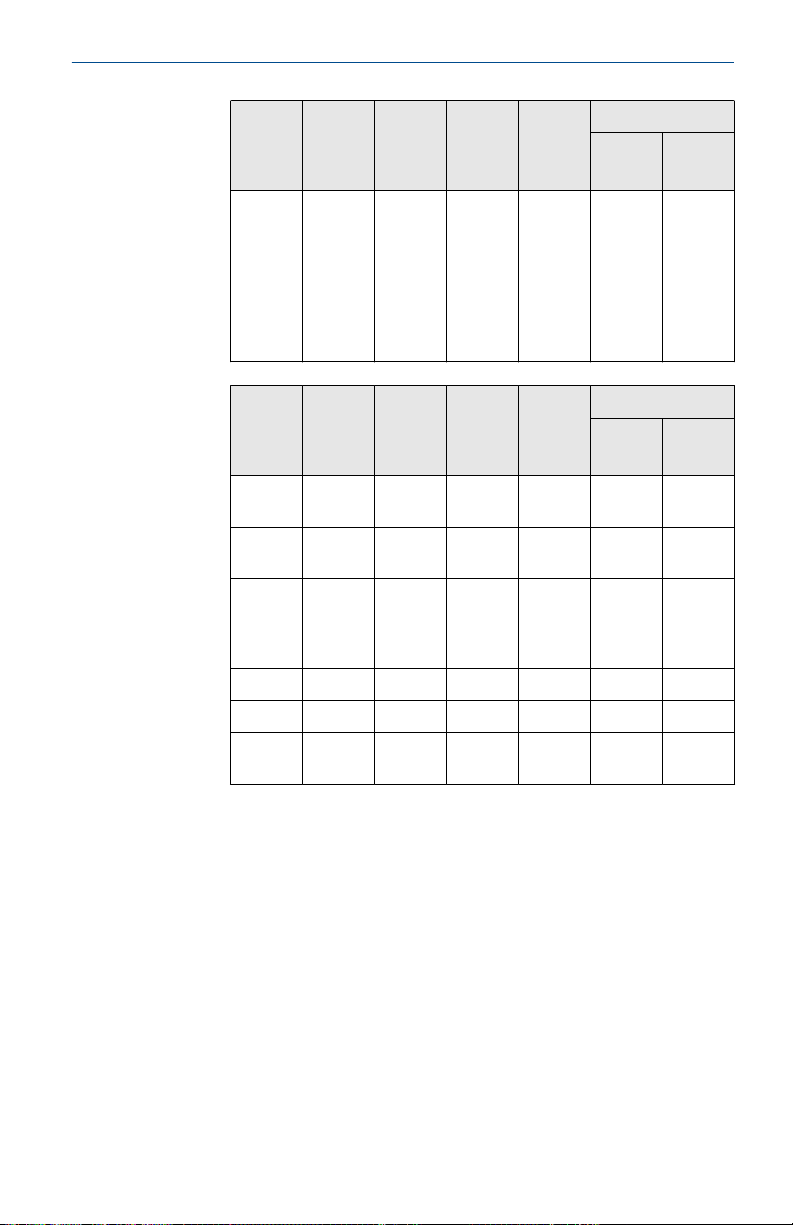
2. 本安电气参数:
型号
3051SA
L_C
3051SA
L_C…
M7/M8
/M9
3051SA
L,
3051SA
M
46 www.Emerson.com
端子 最高输
+, -,
CAN
+, - 30 300 1 12 60
+, -,
CAN
入电压
Ui(V)
30 300 1 12 0
30 300 1 12 33
最大输
入电流
I
i
(mA)
最大输
入功率
P
i
(W)
最大内部等效参数
C
i
(nF)
L
(μH)
i
Page 47
November2024 Quick Start Guide
型号 端子 最高输
入电压
Ui(V)
3051SA
+, - 30 300 1 12 93
最大输
入电流
I
i
(mA)
最大输
入功率
P
i
(W)
最大内部等效参数
C
i
(nF)
L…
M7/M8
/M9
3051SA
M…
M7/M8
/M9
变送器输出端子 最高输
入电压
Ui(V)
Super
module
A +, -,
+, -,
CAN
30 300 1 30 0
30 300 1 12 0
最大输
入电流
I
i
(mA)
最大输
入功率
P
i
(W)
最大内部等效参数
C
i
(nF)
CAN
A 配
+, - 30 300 1 12 60
M7, M8
或 M9
显示
F +, - 30 300 1.3 0 0
FISCO +, - 17.5 380 5.32 0 0
RTD 选项- 5 500 0.63 - -
L
i
(μH)
L
i
(μH)
注: 本安电气参数符合 GB3836.19-2010 对 FISCO 现场仪表的
参数要求.
3. 选择 Remote Mount 选项 M7, M8, M9 时, 电缆分布电容小于
24nF, 分布电感小于 60μH.
4. 该产品必须与已通过防爆认证的关联设备配套共同组成本安防
爆系统方可使用于爆炸性气体环境. 其系统接线必须同时遵守本
产品和所配关联设备的使用说明书要求, 接线端子不得接错.
5. 用户不得自行更换该产品的零部件, 应会同产品制造商共同解决
运行中出现的故障, 以杜绝损坏现象的发生.
6. 用于爆炸性粉尘环境中, 电缆引入口须选用国家指定的防爆检验
机构按检验认可, 具有 Ex tD A20 IP66 防爆等级的电缆引入装置
或堵封件, 冗余电缆引入口须用堵封件有效密封.
www.Emerson.com 47
Page 48

Quick Start Guide November2024
7. 产品的安装, 使用和维护应同时遵守产品使用说明书,
GB3836.13-2013 “爆炸性环境 第 13 部分: 设备的修理, 检修, 修
复和改造”, GB3836.15-2000 “爆炸性气体环境用电气设备 第 15
部分: 危险场所电气安装(煤矿除外)”, GB3836.16-2006 “爆炸
性气体环境用电气设备 第 16 部分: 电气装置的检查和维护(煤
矿除外)”, GB3836.18-2010 “爆炸性环境 第 18 部分: 本质安全
系统” 和 GB50257-2014 “电气装置安装工程爆炸和火灾危险环
境电力装置施工及验收规范” 和 GB15577-2007 “粉尘防爆安全
规程”, GB12476.2-2010 “可燃性粉尘环境用电气设备第 2 部分”:
选型和安装的有关规定.
8.6.3 N3 China Type n
Certificate
Markings
产品安全使用特殊条件
• 产品防爆合格证号后缀 “X” 代表产品安全使用有特殊条件: 产品选用瞬
态保护端子板(c 中包含 T1 选项)时, 设备不能承受 500V 对地电压试
验 1 分钟, 安装时需考虑在内.
• 产品使用注意事项
1. 产品使用环境温度范围为: –40 °C ≤ Ta ≤ +85 °C.
2. 最高输入电压: 45 V.
3. 现场安装时, 电缆引入口须选用经国家指定的防爆检验机构检验
认可的, 具有 Ex eⅡC Gb 或 Ex nA ⅡC Gc 防爆等级的电缆引入
装置或堵封件, 冗余电缆引入口须用堵封件有效密封.
4. 安装现场确认无可燃性气体存在时方可维修.
5. 用户不得自行更换该产品的零部件, 应会同产品制造商共同解决
运行中出现的故障, 以杜绝损坏现象的发生.
6. 产品的安装, 使用和维护应同时遵守产品使用说明书,
GB3836.13-2013 “爆炸性环境 第 13 部分: 设备的修理, 检修, 修
复和改造”, GB3836.15-2000 “爆炸性气体环境用电气设备 第 15
部分: 危险场所电气安装(煤矿除外)”, GB3836.16-2006 “爆炸
性气体环境用电气设备 第 16 部分: 电气装置的检查和维护(煤
矿除外)” , GB50257-2014 “电气装置安装工程爆炸和火灾危险
环境电力装置施工及验收规范” 的有关规定.
3051S,3051SHP: GYJ23.1241X
3051SFx: GYJ23.1245X
Ex ec IIC T5 Gc
8.7
Technical Regulation Custom Union (EAC)
8.7.1 EM EAC Flameproof and Dust Ignition-proof
Certificate
48 www.Emerson.com
EAЭC KZ 7500525.01.01.00672
Page 49

November2024 Quick Start Guide
Markings
0/1 Ex db IIC T6…T4 Ga/Gb X
Ex ta IIIC T105 °C T
8.7.2 IM EAC Intrinsic Safety
Certificate
Markings
EAЭC KZ 7500525.01.01.00672
0Ex ia IIC T4 Ga X
8.7.3 IN EAC Intrinsic Safety
Certificate:
Markings:
EAЭC KZ 7500525.01.01.00672
0Ex ia IIC T4 Ga X
8.8 Japan
8.8.1 E4 Japan Flameproof
Certificate
Markings
Temperature class Ambient temperature Process temperature
T6 –60 to +70 °C –60 to +70 °C
T5 –60 to +80 °C –60 to +80 °C
T4 –60 to +80 °C –60 to +120 °C
CML 17JPN1147X
Ex db IIC T6…T4 Ga/Gb
95 °C Da X
500
Special Conditions for Safe Use:
1. This device contains a thin wall diaphragm less than 1mm
thickness that forms a boundary between EPL Ga (process
connection) and EPL Gb (all other parts of the equipment).
The model code and datasheet are to be consulted for details
of the diaphragm material. Installation, maintenance, and
use shall consider the environmental conditions to which the
diaphragm will be subjected. The manufacturer’s instructions
for installation and maintenance shall be followed in detail to
assure safety during its expected lifetime.
2. Flameproof joints are not intended for repair.
3. Non-standard paint options may cause risk from electrostatic
discharge. Avoid installations that could cause electrostatic
build-up on painted surfaces, and only clean the painted
surfaces with a damp cloth. If paint is ordered through
a special option code, contact the manufacturer for more
information.
www.Emerson.com 49
Page 50

Quick Start Guide November2024
8.9 Republic of Korea
8.9.1 EP Republic of Korea Flameproof
Certificate
19-KA4BO-0913X [Mfg USA], 12-KB4BO-0180X [Mfg USA],
11-KB4BO-0068X [Mfg Singapore]
Markings
Ex d IIC T6…T4 Ga/Gb
8.9.2 IP Republic of Korea Intrinsic Safety
Certificate
Markings
12-KB4BO-0202X [HART® – Mfg USA], 12-KB4BO-0204X
[Fieldbus – Mfg USA], 19-KA4BO-0844X [HART –
Mfg USA], 19-KA4BO-0845X [Fieldbus – Mfg USA], 12KB4BO-0203X [HART – Mfg Singapore], 13-KB4BO-0296X
[Fieldbus – Mfg Singapore], 19-KA4BO-0845X [FieldbusMfg USA], 19-KA4BO-0844X [HART- Mfg USA]
Ex ia IIC T4
8.10 Combinations
K1
Combination of E1, I1, N1, and ND
K2
Combination of E2 and I2
K5
Combination of E5 and I5
K6
Combination of E6 and I6
K7
Combination of E7, I7, and N7
KA
Combination of E1, I1, E6, and I6
KB
Combination of E5, I5, E6, and I6
KC
Combination of E1, I1, E5, and I5
KD
Combination of E1, I1, E5, I5, E6, and I6
KG
Combination of IA, IE, IF, and IG
KM
Combination of EM and IM
KP
Combination of EP and IP
8.11 Additional certifications
8.11.1 SBS American Bureau of Shipping (ABS) Type Approval
Certificate
50 www.Emerson.com
17-RJ1679518-PDA
Page 51

November2024 Quick Start Guide
Intended Use
Measure gauge or absolute pressure of liquid, gas
or vapor applications on ABS classed vessels, marine,
and offshore installations.
8.11.2 SBV Bureau Veritas (BV) Type Approval
Certificate
Requirements
Application
31910 BV
Bureau Veritas Rules for the Classification of Steel
Ships
Class Notations: AUT-UMS, AUT-CCS, AUT-PORT and
AUT-IMS.
8.11.3 SDN Det Norske Veritas (DNV) Type Approval
Certificate
Intended Use
Application
Location classes
Type 3051S
Temperature D
Humidity B
Vibration A
EMC A
Enclosure D/IP66/IP68
TAA00000K9
Det Norske Veritas' Rules for Classification of Ships,
High Speed & Light Craft, and Det Norske Veritas'
Offshore Standards
8.11.4 SLL Lloyds Register (LR) Type Approval
Certificate
Application
LR21173788TA
Environmental categories ENV1, ENV2, ENV3, and ENV5
8.11.5 D3 Custody Transfer - Measurement Canada Accuracy Approval [3051S Only]
Certificate
www.Emerson.com 51
AG-0501, AV-2380C
Page 52

Quick Start Guide November2024
8.12 Y3 ATEX/IECEx RFID tag approvals
Certificate
Markings
Conditions of certification
Maximum operating temperature: -58 °F (-50 °C) to +158 °F (+70 °C)
The RFID tags shall never be exposed to high electromagnetic field
strengths according to IEC 60079-14.
Electrostatic charges shall be avoided. The tags shall never be used
next to strong charge generating processes.
IECEx EPS 15.0042X, EPS 15 ATEX 1 1011 X
II 2G Ex ia IIC T6/T4 Gb, II 2D Ex ia IIC T80/T130C
Db
WARNING
Additional warnings
The plastic enclosure may present a potential electrostatic ignition
hazard.
RFID tag has limitations in ambient temperature and zone installation
areas (Zones 1 & 21) as compared to the gauge.
52 www.Emerson.com
Page 53
November2024 Quick Start Guide
9 Declaration of Conformity
www.Emerson.com 53
Page 54

Quick Start Guide November2024
54 www.Emerson.com
Page 55
November2024 Quick Start Guide
www.Emerson.com 55
Page 56
Quick Start Guide November2024
56 www.Emerson.com
Page 57
ᴹ
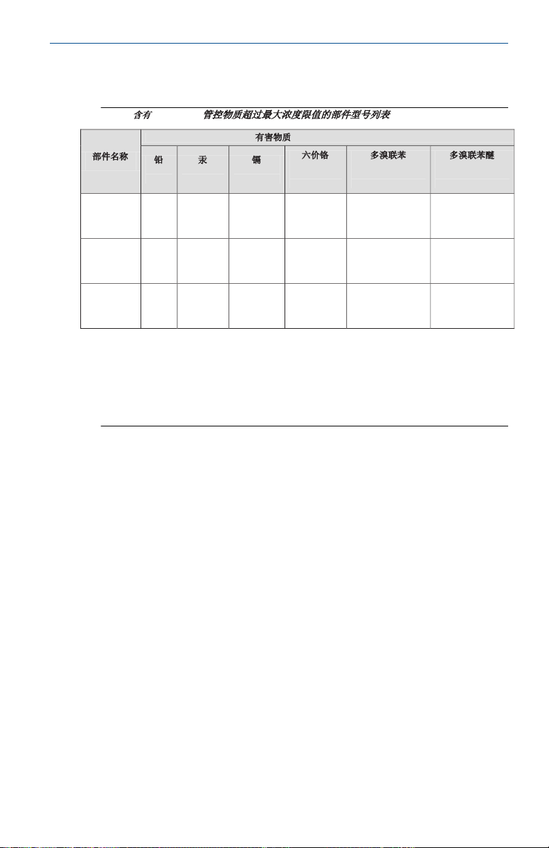
China RoHS
㇑᧗⢙䍘䎵䗷ᴰབྷ⎃ᓖ䲀٬Ⲵ䜘Ԧරࡇ㺘
Rosemount 3051S
List of Rosemount 3051S Parts with China RoHS Concentration above MCVs
䜘Ԧ〠
Part Name
ᴹᇣ⢙䍘
/ Hazardous Substances
䫵
Lead
(Pb)
⊎
Mercury
(Hg)
䭹
Cadmium
(Cd)
ޝԧ䬜
Hexavalent
Chromium
(Cr +6)
ཊⓤ㚄㤟
Polybrominated
biphenyls
(PBB)
ཊⓤ㚄㤟䟊
Polybrominated
diphenyl ethers
(PBDE)
⭥ᆀ㓴Ԧ
Electronics
Assembly
X O O O O O
༣փ㓴Ԧ
Housing
Assembly
X O O X O O
Րᝏಘ㓴Ԧ
Sensor
Assembly
X O O X O O
ᵜ㺘Ṭ㌫ᦞ
SJ/T11364
Ⲵ㿴ᇊ㘼ࡦ
This table is proposed in accordance with the provision of SJ/T11364.
O:
Ѫ䈕䜘ԦⲴᡰᴹ൷䍘ᶀᯉѝ䈕ᴹᇣ⢙䍘Ⲵ䟿൷վҾ
GB/T 26572
ᡰ㿴ᇊⲴ䲀䟿㾱≲
O: Indicate that said hazardous substance in all of the homogeneous materials for this part is below the limit requirement of
GB/T 26572.
X:
Ѫ൘䈕䜘Ԧᡰ֯⭘Ⲵᡰᴹ൷䍘ᶀᯉ䟼ˈ㠣ቁᴹа㊫൷䍘ᶀᯉѝ䈕ᴹᇣ⢙䍘Ⲵ䟿儈Ҿ
GB/T 26572
ᡰ㿴ᇊⲴ䲀䟿㾱≲
X: Indicate that said hazardous substance contained in at least one of the homogeneous materials used for this part is above
the limit requirement of GB/T 26572.
November2024 Quick Start Guide
10 China RoHS
www.Emerson.com 57
Page 58

Quick Start Guide November2024
58 www.Emerson.com
Page 59

November2024 Quick Start Guide
www.Emerson.com 59
Page 60

*00825-0100-4801*
Quick Start Guide
00825-0100-4801, Rev. PC
November2024
For more information:Emerson.com/global
©
2024 Emerson. All rights reserved.
Emerson Terms and Conditions of
Sale are available upon request. The
Emerson logo is a trademark and
service mark of Emerson Electric Co.
Rosemount is a mark of one of the
Emerson family of companies. All
other marks are the property of their
respective owners.
 Loading...