

Emerson Rosemount 3051N Datasheet
Product Data Sheet
March 2021
00813-0100-4808, Rev HA
Rosemount™ 3051N Smart Pressure Transmitter
for Nuclear Service
Industry leading performance
Qualified per IEEE Std 344-1987 and IEEE Std 323-1983 (mild environment)
Superior performance with ±0.075% accuracy
100:1 rangeability reduces inventory costs
Non-interacting zero and span adjustment reduces calibration time
Adjustable damping
Internal diagnostics
Coplanar sensor/process interface for maximum mounting flexibility
Rosemount 3051N
00813-0100-4808, Rev HA
Results driven by proven measurement
Product Data Sheet
March 2021
Introduction
Rosemount 3051N Coplanar™ Smart Pressure Transmitters are
designed for precision differential, gauge, and absolute pressure
measurements requiring reliable performance and safety. These
transmitters are seismically qualified for use in Class 1E safety
related applications per IEEE Std 344-1987 at SSE response
spectrum levels up to 16.5g’s, and per IEEE Std 323-1983 (mild
environment).
Transmitter functional operation and design
The Rosemount 3051N is designed with a unique patented
coplanar sensor/process interface. Performance and reliability
improvements over traditional designs are achieved by moving the
transmitter sensor from the flange interface into the module neck,
thereby reducing flange stress, thermal, and process interface
effects. The coplanar sensor platform also allows greater flexibility
in process interfaces and mounting configurations.
For differential and gauge pressure measurements, the Rosemount
3051N utilizes capacitance sensor technology similar to that of the
Rosemount 3152N, 3153N, and 3154N Transmitters (see Figure
1). Rosemount capacitance technology delivers the highest
inherent performance, stability and reliability in the process
industry as proven in millions of installations worldwide.
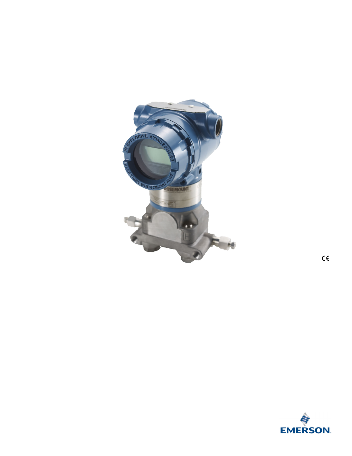
Figure 1. Rosemount 3051ND/NG Sensor Module
Typical Cut-away Diagrams
Contents
Introduction . . . . . . . . . . . . . . . . . . . . . . . . . . . . . . . . . . . . . 2
Transmitter functional operation and design . . . . . . . . . 2
Nuclear specifications . . . . . . . . . . . . . . . . . . . . . . . . . . . . . 4
Performance specifications . . . . . . . . . . . . . . . . . . . . . . . . 5
2
A. Center diaphragm
B. Rigid insulation
C. Capacitor plates
D. Silicone oil
E. Isolating diaphragms
Functional specifications . . . . . . . . . . . . . . . . . . . . . . . . . . .6
Physical specifications . . . . . . . . . . . . . . . . . . . . . . . . . . . . . 8
Ordering Information . . . . . . . . . . . . . . . . . . . . . . . . . . . . .14
Emerson.com/Rosemount
Product Data Sheet
A
B
C
D
H
I
J
L
K
E
F
F
AG
N
M
March 2021
Rosemount 3051N
00813-0100-4808, Rev HA
During operation, process pressure is transmitted through
isolating diaphragms and silicone oil fill fluid to a center diaphragm
in the alpha-cell capacitance sensor (see Figure 1). The
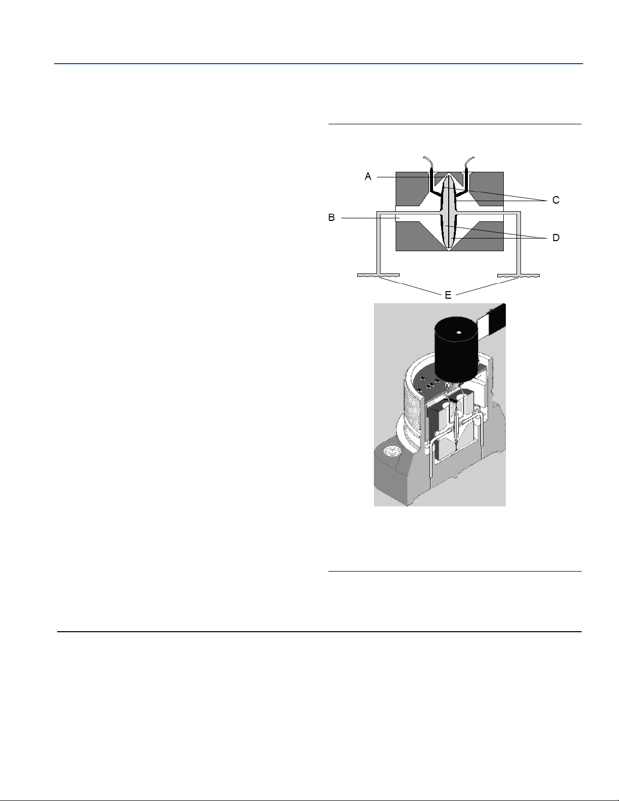
Figure 2. Rosemount 3051NA Sensor Module
Typical Cut-away Diagram
displacement of the center diaphragm is proportional to the
pressure differential across it. The position of the center
diaphragm is detected through differential capacitance between it
and capacitor plates located on each side. The differential
capacitance is processed electronically through a microprocessor
®
to a 2 wire 4—20mA (digital) HART
(Highway Addressable Remote
Transducer) output signal. Each unit completes a compensation
and verification process during manufacturing where the unique
sensor characteristics are measured over pressure and
temperature and retained in the device to optimize performance
over a wide operating range.
For absolute pressure measurements, the Rosemount 3051N
utilizes piezoelectric silicon sensor technology designed and
manufactured at the Rosemount Solid State Technology Center
A. Piezoelectric silicon sensor
(see Figure 2).
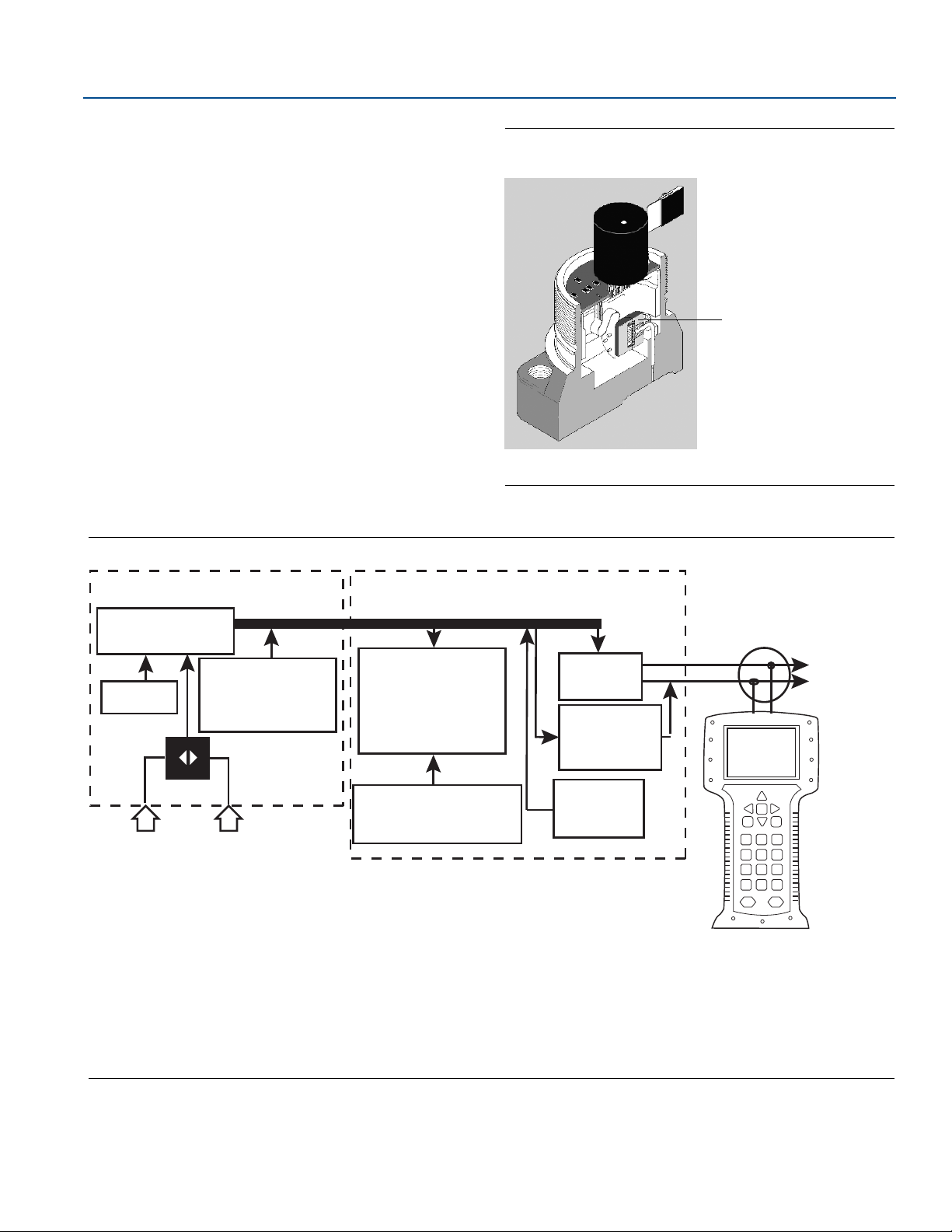
Figure 3. Rosemount 3051N Differential Pressure Transmitter 4—20 mA Block Diagram
A. Sensor module
B. Signal processing
C. Temperature sensor
D. Sensor module memory
E. Capacitive sensor
F. Pressure
G. Electronics board
Emerson.com/Rosemount
H. Microcomputer (sensor linearization, rerange, damping, diagnostics,
engineering, communication)
I. Digital-to-analog signal
J. Digital communication
K. Module memory (rerange values, configuration)
L. Local span and zero adjustment
M. 4-20 mA signal to control system
N. HART Communicator 275, 375, or 475
3

Rosemount 3051N
00813-0100-4808, Rev HA
Specifications
Nuclear specifications
Qualified for nuclear use per IEEE Std 344-1987 and IEEE Std
323-1983 (mild environment) as documented in Rosemount
Report D2001019.
Seismic
Table 1. Seismic Specifications Summary
Model
Range
code
During seismic accuracy
(1)
Post seismic
accuracy
Specified seismic maximum
working pressure
Product Data Sheet
March 2021
Structural integrity
3051ND
3051NG
3051NA
(2)
0
(adjustable damping 3.2 s)
1.5% of URL
0.75% of URL
(3)
1
(adjustable damping 1.6 s)
0.75% of URL
(3)
2
Differential
(adjustable damping 0.8 s)
30.75% of URL
4
5
0.25% of URL
0.75% of URL
(3)
2
(adjustable damping 0.8 s)
30.75% of URL
Gauge
4
5
1
0.25% of URL
not specified not specified
2
3
Absolute
0.25% of URL 0.25% of span
4
0.25% of URL 750 psi (5,2 MPa)
2000 psi (13,8 MPa)
3000 psi (20,7 MPa)
(glass-filled TFE O-ring)
2000 psi (13,8 MPa)
0.25% of span
(EPR O-ring)
Upper Range Limit
3000 psia (20,7 MPa)
(glass-filled TFE O-ring)
2000 psi (13,8 MPa)
(EPR O-ring)
Maintained throughout
specified seismic
disturbance
1. User-adjustable damping set at 0.4 s unless otherwise noted.
2. Mounting bracket Option Code BS required for Range 0 specified “During Seismic Accuracy” performance.
3. Mounting bracket (Option Code B2, BS, or PM) required for specified “During Seismic Accuracy” performance.
Environmental
Performance to normal operating limits as described in the
Performance specifications and Functional specifications sections
of this document.
Hydrostatic testing
Model Range code Hydrostatic test pressure
3051ND
Quality assurance program
In accordance with 10CFR50 Appendix B, ISO 9001:2008
Nuclear cleaning
To 1 ppm chloride content
3051NG 2—5
3051NA 1—4
1. Process O-ring Code A (glass filled TFE).
2. Maximum working pressure equals upper range limit (URL).
4
0
1
2—5
(1)
750 psi
2000 psi
4200 psi
150% of maximum
working pressure
(2)
Emerson.com/Rosemount

Product Data Sheet
March 2021
Rosemount 3051N
00813-0100-4808, Rev HA
Performance specifications
Based upon zero-based calibrations, reference conditions,
4—20mA analog output, and digital trim values equal to the span
setpoints
Reference accuracy
Includes hysteresis, terminal-based linearity, and repeatability
Rosemount 3051ND
Range
code
2 — 5
Reference accuracy
± 0.10% calibrated span from 1:1 to 2:1 RDF
0
± 0.05% upper range limit from 2:1 to 30:1 RDF
± 0.10% calibrated span from 1:1 to 15:1 RDF
1
± (0.005% URL + 0.025% span)
from 15:1 to 50:1 RDF
± 0.075% calibrated span from 1:1 to 10:1 RDF
± (0.005% URL + 0.025% span)
from 10:1 to 100:1 RDF
Rosemount 3051NG
(1)
Ambient temperature effect
Rosemount 3051ND/NG
Range
code
2 — 5
Range
code
1 — 4
Overpressure effect
Maximum zero shift after overpressure of Maximum Working
Pressure
Ambient temperature effect per 50° F
(28° C)
0 ± (0.25% URL + 0.05% span)
± (0.1% URL + 0.25% span) from 1:1 to 30:1
1
± (0.14% URL + 0.15% span) from 30:1 to 50:1
± (0.0125% URL + 0.0625% span) from 1:1 to 5:1
± (0.025% URL + 0.125% span) from 5:1 to 100:1
Rosemount 3051NA
Ambient temperature effect per 50° F
(28° C)
± (0.025% URL + 0.125% span) from 1:1 to 30:1
± (0.035% URL + 0.125% span) from 30:1 to 100:1
(1)(2)
Range
code
2 — 5
Range
code
1 — 4
Reference accuracy
± 0.075% calibrated span from 1:1 to 10:1 RDF
± (0.005% URL + 0.025% span)
from 10:1 to 100:1 RDF
Rosemount 3051NA
Reference accuracy
± 0.075% calibrated span from 1:1 to 10:1 RDF
± (0.0075% URL) from 10:1 to 100:1 RDF
Drift
Rosemount 3051ND, NG, NA
Range
code
2 — 5 ± 0.2% URL for 30 months
Drift
1 ± (0.2% URL + 0.2% span) for 30 months
Rosemount 3051ND
Range
code
0 — 3 ± 0.5% URL
4 — 5 ± 3.0% URL
Range
code
2 — 4 ± 0.25% URL
Range
code
1 — 4 ± 0.05% URL
Overpressure effect
Rosemount 3051NG
Overpressure effect
5± 0.30% URL
Rosemount 3051NA
Overpressure effect
1. RDF = Range Down Factor = URL / Calibrated Span
Emerson.com/Rosemount
2. Exposure of isolator diaphragms to process temperatures above 185 °F
(85 °C) but below 250 °F (121 °C) produces a temperature effect of ±
calibrated span in addition to the effects listed.
1.0% of
5
 Loading...