

Quick Start Guide
00825-0100-4797, Rev HA
January 2020
Rosemount™ 3051 Pressure Transmitter
and Rosemount 3051CF Series Flow
Meter
with PROFIBUS® PA Protocol

Quick Start Guide January 2020
Contents
About this guide...........................................................................................................................3
Transmitter installation................................................................................................................ 5
Basic configuration.....................................................................................................................26
Trim the transmitter...................................................................................................................29
Product certifications................................................................................................................. 30
2 Emerson.com/Rosemount

January 2020 Quick Start Guide
1 About this guide
This guide provides basic guidelines for Rosemount 3051 Transmitters. It
does not provide instructions for configuration, diagnostics, maintenance,
service, troubleshooting, Explosion-Proof, Flame-Proof, or intrinsically safe
(I.S.) installations. Refer to the Rosemount 3051 Reference Manual for more
instructions. This manual is also available electronically on Emerson.com/
Rosemount.
1.1 Safety messages
Before installing the transmitter, confirm the correct device driver is loaded
on the host systems.
Procedures and instructions in this section may require special precautions
to ensure the safety of the personnel performing the operations.
NOTICE
This guide provides basic guidelines for Rosemount 3051 Transmitters. It
does not provide instructions for configuration, diagnostics, maintenance,
service, troubleshooting, Explosion-Proof, Flame-Proof, or intrinsically safe
(I.S.) installations. Refer to the Rosemount 3051 Reference Manual
Rosemount 3051 Reference Manual for more instructions. This manual is
also available electronically on Emerson.com/Rosemount.
WARNING
Explosions
Explosions could result in death or serious injury.
Installation of this transmitter in an explosive environment must be in
accordance with the local, national, and international standards, codes,
and practices. Review product certifications for any restrictions
associated with a safe installation.Review the Product certifications
section of the Rosemount 3051 Product Data Sheet for any restrictions
associated with a safe installation.
Before connecting a handheld communicator in an explosive
atmosphere, ensure that the instruments in the loop are installed in
accordance with intrinsically safe or non-incendive field wiring practices.
In an explosion-proof/flameproof installation, do not remove the
transmitter covers when power is applied to the unit.
Quick Start Guide 3

Quick Start Guide January 2020
WARNING
Process leaks
Process leaks could result in death or serious injury.Process leaks may cause
harm or result in death.Process leaks may cause harm or result in death.
Install and tighten process connectors before applying pressure.
To avoid process leaks, only use the O-ring designed to seal with the
corresponding flange adapter.
Electrical shock
Electrical shock could cause death or serious injury.Electrical shock can result
in death or serious injury.Electrical shock can result in death or serious injury.
Avoid contact with the leads and terminals. High voltage that may be
present on leads can cause electrical shock.
Conduit/cable entries
Unless marked, the conduit/cable entries in the transmitter housing use a
½–14 NPT thread form. Entries marked “M20” are M20 × 1.5 thread form.
On devices with multiple conduit entries, all entries will have the same
thread form. Only use plugs, adapters, glands, or conduit with a compatible
thread form when closing these entries.
When installing in a hazardous location, use only appropriately listed or Ex
certified plugs, glands, or adapters in cable/conduit entries.
Physical access
Unauthorized personnel may potentially cause significant damage to and/or
misconfiguration of end users’ equipment. This could be intentional or
unintentional and needs to be protected against.
Physical security is an important part of any security program and
fundamental to protecting your system. Restrict physical access by
unauthorized personnel to protect end users’ assets. This is true for all
systems used within the facility.
4 Emerson.com/Rosemount
January 2020 Quick Start Guide
2 Transmitter installation
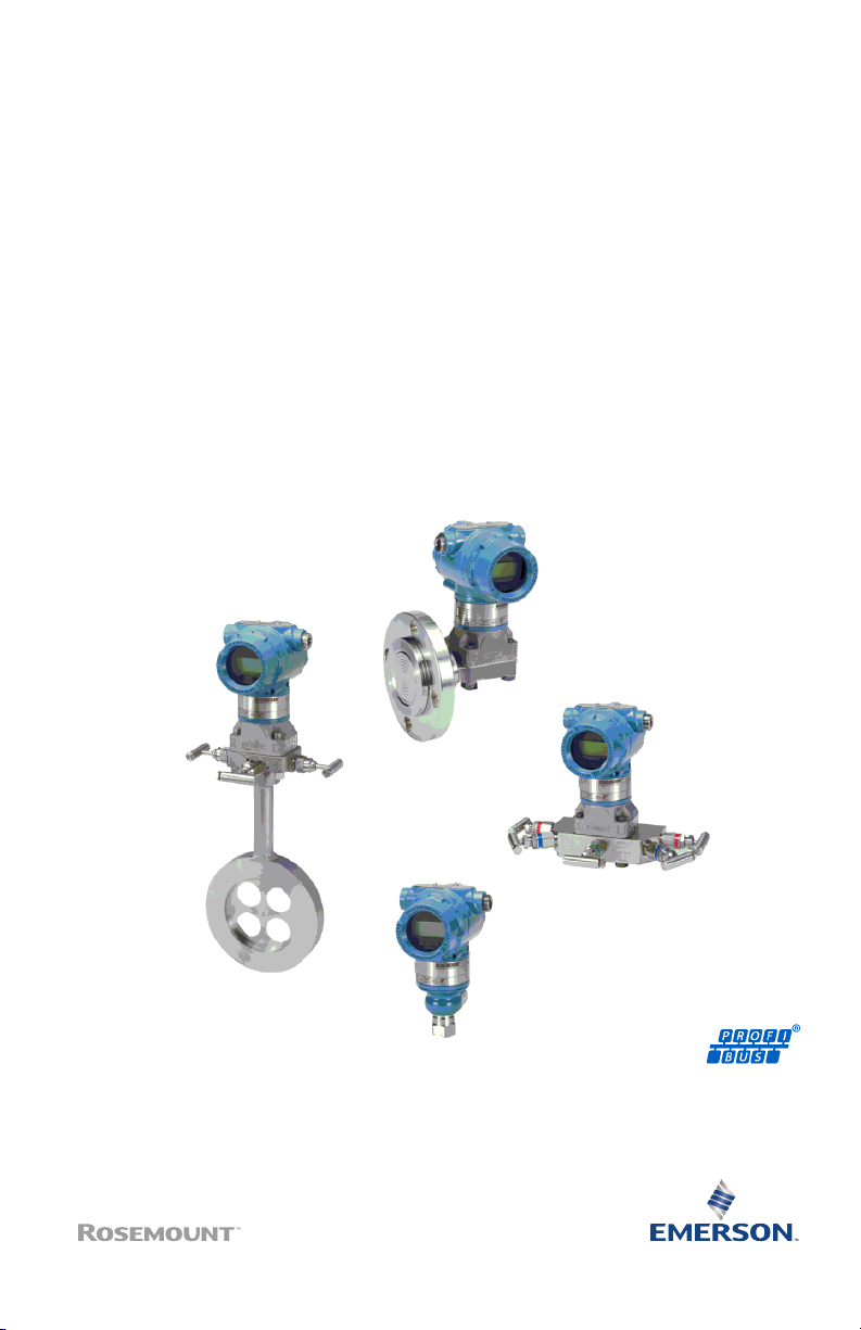
2.1 Mount the transmitter
For dimensional drawing information refer to the Dimensional Drawings
section of the Rosemount 3051 Product Data Sheet.
Figure 2-1: Panel Mount Coplanar Flange
5/16 x 1½ panel bolts are customer supplied.
Quick Start Guide 5
Quick Start Guide January 2020
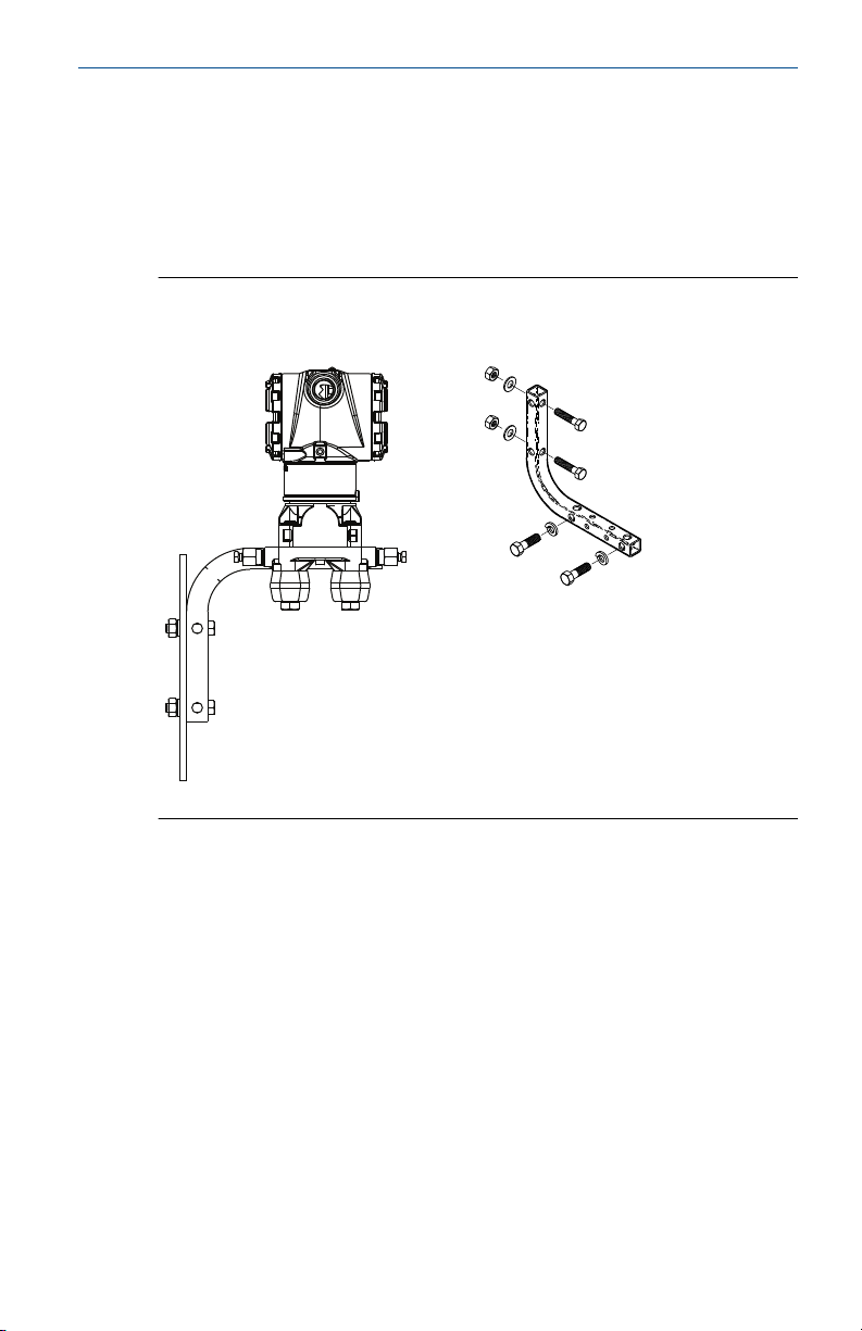
Figure 2-2: Pipe Mount Coplanar Flange
Figure 2-3: Panel Mount Traditional Flange
Figure 2-4: Pipe Mount Traditional Flange
6 Emerson.com/Rosemount
January 2020 Quick Start Guide
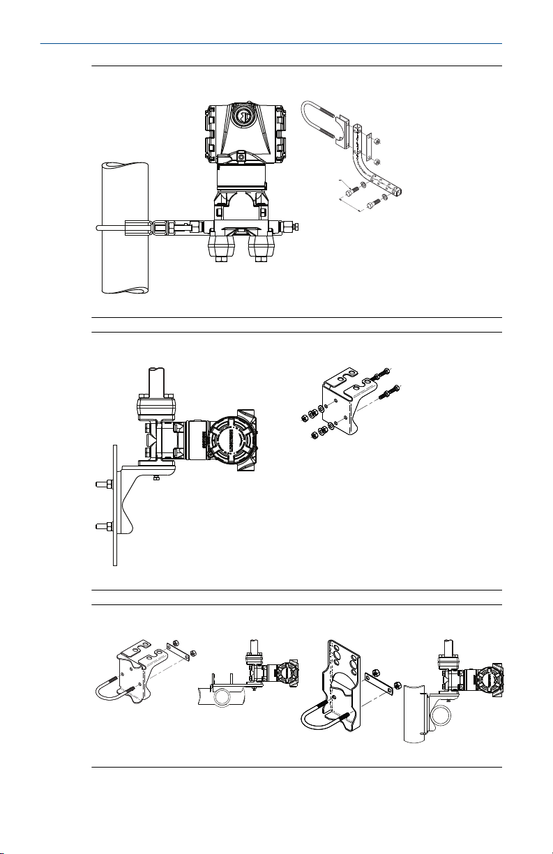
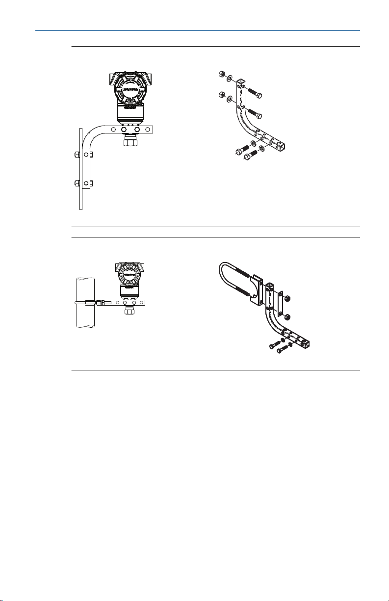
Figure 2-5: Panel Mount Rosemount 3051T
Figure 2-6: Pipe Mount Rosemount 3051T
Quick Start Guide 7
Quick Start Guide January 2020
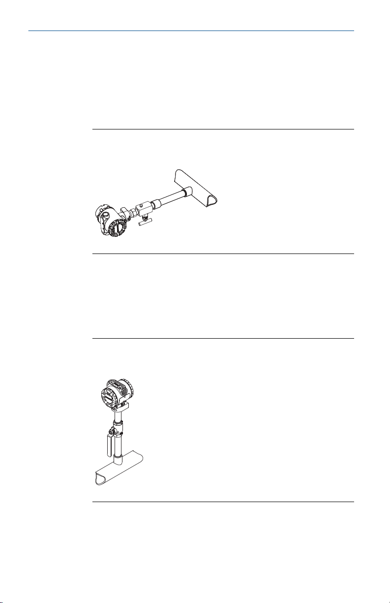
2.1.1 Mount the transmitter in liquid applications
Procedure
1. Place taps to the side of the line.
2. Mount beside or below the taps.
3. Mount the transmitter so the drain/vent valves are oriented upward.
Figure 2-7: Mounting the Transmitter in Liquid Applications
In-line
2.1.2 Mount the transmitter in gas applications
Procedure
1. Place taps in the top or side of the line.
2. Mount beside or above the taps.
Figure 2-8: Mounting the Transmitter in Gas Applications
In-line
8 Emerson.com/Rosemount
January 2020 Quick Start Guide
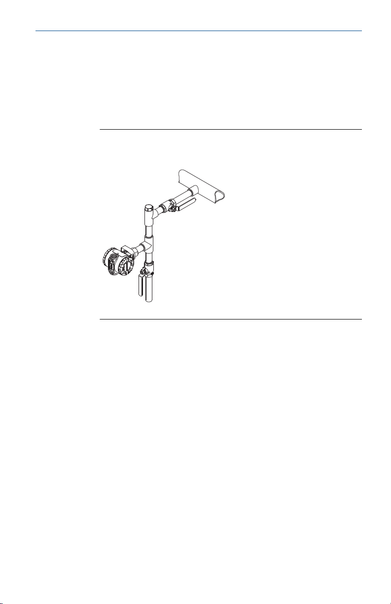
2.1.3 Mount the transmitter in steam applications
Procedure
1. Place taps to the side of the line.
2. Mount beside or below the taps.
3. Fill impulse lines with water.
Figure 2-9: Mounting the Transmitter in Steam Applications
In-line
2.1.4 Bolting consideration
If the transmitter installation requires assembly of the process flanges,
manifolds, or flange adapters, follow the assembly guidelines to ensure a
tight seal for optimal performance characteristics of the transmitters.
Use only bolts supplied with the transmitter or sold by Emerson as spare
parts. Figure 2-10 illustrates common transmitter assemblies with the bolt
length required for proper transmitter assembly.
Quick Start Guide 9
B
4 × 2.88-in. (73 mm)
A
4 × 1.75-in. (44 mm)
C
4 × 1.75-in.
(44 mm)
4 × 1.50-in.
(38 mm)
D
4 × 1.75-in. (44 mm)
4 × 2.25-in. (57 mm)
B7M
316
316
316
SW
316
STM
316
R
B8M
Quick Start Guide January 2020
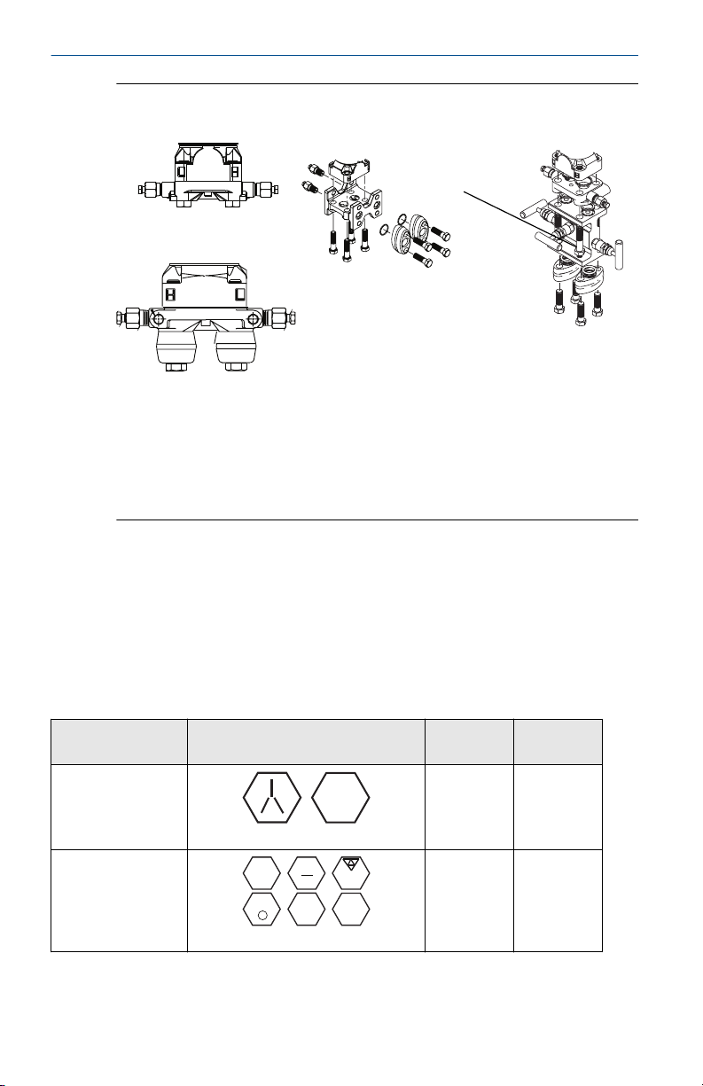
Figure 2-10: Common Transmitter Assemblies
A. Transmitter with coplanar flange
B. Transmitter with coplanar flange and optional flange adapters
C. Transmitter with traditional flange and optional flange adapters
D. Transmitter with coplanar flange and optional manifold and flange
adapters
Bolts are typically carbon steel or stainless steel. Confirm the material by
viewing the markings on the head of the bolt and referencing Table 2-1. If
bolt material is not shown in Table 2-1, contact a local Emerson
representative for more information.
Carbon steel bolts do not require lubrication, and the stainless steel bolts are
coated with a lubricant to ease installation. However, do not apply additional
lubricant when installing either type of bolt.
Table 2-1: Torque Values for the Flange and Flange Adapter Bolts
Bolt material Head markings Initial
torque
300 in-lb 650 in-lb
Final
torque
Carbon Steel (CS)
Stainless Steel (SST)
Use the following bolt installation procedure:
10 Emerson.com/Rosemount
150 in-lb 300 in-lb
A
B
C
D
Rosemount 3051S/3051/2051
January 2020 Quick Start Guide
Procedure
1. Use the fingers to tighten the bolts.
2. Torque the bolts to the initial torque value using a crossing pattern.
See Table 2-1 for initial torque value.
3. Torque the bolts to the final torque value using the same crossing
pattern.
See Table 2-1 for final torque value.
4. Verify the flange bolts are protruding through the sensor module
bolt holes before applying pressure.
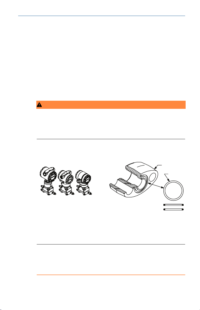
2.1.5 O-rings with flange adapters
WARNING
Failure to install proper flange adapter O-rings may cause process leaks,
which can result in death or serious injury. The two flange adapters are
distinguished by unique O-ring grooves. Only use the O-ring that is designed
for its specific flange adapter, as shown below.
Figure 2-11: O-ring Location
A. Flange adapter
B. O-ring
C. PFTE-based profile (square)
D. Elastomer profile (round)
Whenever the flanges or adapters are removed, visually inspect the O-rings.
Replace them if there are any signs of damage, such as nicks or cuts. If you
replace the O-rings, re-torque the flange bolts and alignment screws after
installation to compensate for seating of the PTFE O-ring.
Quick Start Guide 11
A
Quick Start Guide January 2020
2.1.6 Environmental seal for housing
For NEMA® 4X, IP66, and IP68 requirements, use thread sealing (PTFE) tape
or paste on male threads of conduit to provide a water and dust tight seal.
Consult factory if other ingress protection ratings are required.
Always ensure a proper seal by installing the electronics housing cover(s) so
that metal contacts metal. Use Rosemount™ O-rings.
For M20 threads, install conduit plugs to full thread engagement or until
mechanical resistance is met.
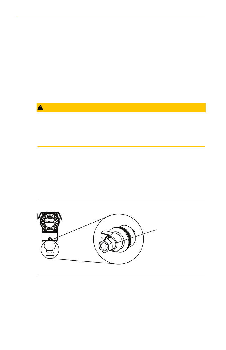
2.1.7 Inline gage transmitter orientation
CAUTION
Erroneous pressure values
The transmitter may output erroneous pressure values.
Do not interfere or block the atmospheric reference port.
The low side pressure port on the inline gage transmitter is located in the
neck of the transmitter, behind the housing.The low side pressure port
(atmospheric reference) on the inline gage transmitter is located in the neck
of the transmitter, behind the housing. The vent path is 360 degrees around
the transmitter between the housing and sensor (see Figure 2-12).
Keep the vent path free of any obstruction, such as paint, dust, and
lubrication, by mounting the transmitter so that the process can drain away.
Figure 2-12: Inline Gage Low Side Pressure Port
A. Low side pressure port (atmospheric reference)
12 Emerson.com/Rosemount
A
B
January 2020 Quick Start Guide
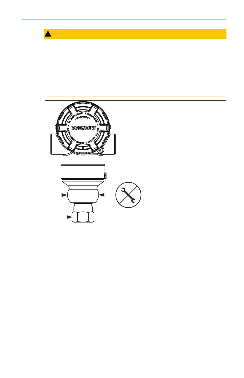
CAUTION
Electronics damage
Rotation between the sensor module and the process connection can
damage the electronics.
Do not apply torque directly to the sensor module.
To avoid damage, apply torque only to the hex-shaped process
connection.
A. Sensor module
B. Process connection
2.1.8 Install high pressure coned and threaded connection
The transmitter comes with an autoclave connection designed for pressure
applications. Follow the steps below to properly connect the transmitter to
your process.
Procedure
1. Apply a process-compatible lubricant to the gland nut threads.
2. Slip the gland nut onto the tube; then thread the collar onto the tube
end.
The collar is reverse threaded.
Quick Start Guide 13
Commissioning Tag
DEVICE ID:
0011513051010001440-12169809172 5
DEVICE REVISION: 7.2
PHYSICAL DEVICE TAG
DEVICE ID:
0011513051010001440-12169809172 5
DEVICE REVISION: 7.2
S / N :
PHYSICAL DEVICE TAG
Device Barcode
A
Commissioning Tag
DEVICE ID:
001151AC00010001440-1216980917 25
DEVICE REVISION: 8.1
PHYSICAL DEVICE TAG
DEVICE ID:
001151AC00010001440-121698091725
DEVICE REVISION: 8.1
S / N :
PHYSICAL DEVICE TAG
Device Barcode
Quick Start Guide January 2020
3. Apply a small amount of process-compatible lubricant to the tube
cone to help prevent galling and facilitate sealing. Insert the tubing
into the connection and use the fingers to tighten the bolts.
4. Tighten the gland nut to a torque of 25 ft-lb.
Note
A weep hole has been designed into the transmitter for safety and
leak detection. If fluid begins to leak from the weep hole, isolate the
process pressure, disconnect the transmitter, and reseal until the
leak is resolved.
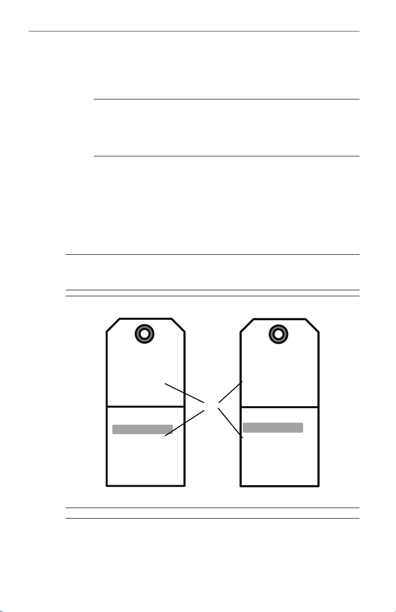
2.2 Tagging
2.2.1 Commissioning (paper) tag
To identify which device is at a particular location, use the removable tag
provided with the transmitter. Ensure the physical device tag (PD tag field) is
properly entered in both places on the removable commissioning tag and
tear off the bottom portion for each transmitter.
Note
The device description loaded in the host system must be at the same
revision as this device.
Figure 2-13: Commissioning Tag
14 Emerson.com/Rosemount
A. Device revision
Note
The device description loaded in the host system must be at the same
revision as this device. You can download the device description from the
host system website or Emerson.com/Rosemount by selecting Device
A
January 2020 Quick Start Guide
Drivers under Resources. You can also visit Fieldbus.org and select End User
Resources.
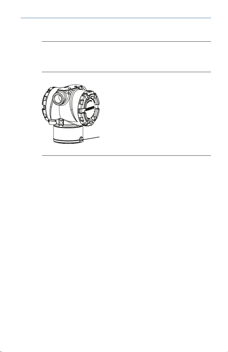
2.3 Consider housing rotation
To improve field access to wiring or to better view the optional LCD display:
Figure 2-14: Housing Rotation
A. Housing rotation set screw (5/64-in.)
Procedure
1. Loosen the housing rotation set screw using a 5/64-in. hex wrench.
2. Rotate the housing clockwise to the desired location.
3. If the desired location cannot be achieved due to thread limit, rotate
the housing counterclockwise to the desired location (up to 360°
from thread limit).
4. Retighten the housing rotation set screw to no more than 7 in-lb
when it reaches the desired location.
2.4
Set jumpers and switches
2.4.1 Security
After the transmitter is configured, you may want to protect the
configuration data from unwarranted changes. Each transmitter is equipped
with a security jumper that can be positioned ON to prevent the accidental
or deliberate change of configuration data. The jumper is labeled “Security”.
The security jumper also prevents changes made using the Local Operator
Interface.
2.4.2 Simulate
The simulate jumper is used in conjunction with the analog input (AI) block.
This jumper is used to simulate the pressure measurement and is used as a
lock-out feature for the AI block. to enable the simulate feature, the jumper
Quick Start Guide 15

Quick Start Guide January 2020
must be moved to the “ON” position after power is applied. This feature
prevents the transmitter from being accidentally left in simulate mode.
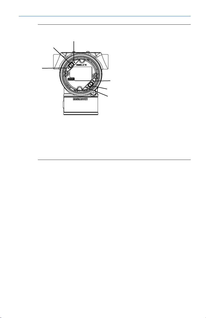
Figure 2-15: Transmitter Jumper Locations
2.5 Set the switches
Use the following procedure to change the switch configuration:
Set Simulate and Security switch configuration before installation as shown
in Figure 2-16.
• The Simulate switch enables or disables simulated alerts and simulated
AI Block status and values. The default Simulate switch position is
Enabled.
• The Security switch allows (unlocked symbol) or prevents (locked
symbol) any configuration of the transmitter.
— Default Security is Off (unlocked symbol).
— You can enable or disable the Security switch in the software.
Procedure
1. If the transmitter is installed, secure the loop and remove power.
2. Remove the housing cover opposite the field terminal side. Do not
remove the instrument cover in explosive atmospheres when the
circuit is live.
3. Slide the Security and Simulate switches into the preferred position.
4. Replace the housing cover.
Note
Emerson recommends tightening the cover until there is no gap between
the cover and the housing.
16 Emerson.com/Rosemount
C
A
B
D
E
F
January 2020 Quick Start Guide
Figure 2-16: Simulate and Security Switches
A. Simulate disabled position
B. Simulate switch
C. Simulate enabled position
D. Security locked position
E. Security switch
F. Security unlocked position
2.6 Connect wiring and power up
Use copper wire of sufficient size to ensure that the voltage across the
transmitter power terminals does not drop below 9 Vdc. Power supply
voltage can be variable, especially under abnormal conditions, such as when
operating on battery backup. Emerson recommends a minimum of 12 Vdc
under normal operating conditions and shielded twisted pair Type A cable.
Procedure
1. To power the transmitter, connect the power leads to the terminals
indicated on the terminal block label.
Quick Start Guide 17

DP
A
A
D
E
B
C
Quick Start Guide January 2020
Figure 2-17: Wiring Terminals
A. Minimize distance
B. Trim shield and insulate
C. Protective grounding terminal (do not ground cable shield at the
transmitter)
D. Insulate shield
E. Connect shield back to the power supply ground
Note
The Rosemount 3051 power terminals are polarity insensitive, which
means the electrical polarity of the power leads does not matter
when connecting to the power terminals. If polarity sensitive devices
are connected to the segment, follow terminal polarity. When wiring
to the screw terminals, Emerson recommends using crimped legs.
2. Ensure full contact with terminal block screw and washer. When
using a direct wiring method, wrap wire clockwise to ensure it is in
place when tightening the terminal block screw.
Note
Emerson does not recommend using a pin or ferrule wire terminal, as
the connection may be more susceptible to loosening over time or
under vibration.
18 Emerson.com/Rosemount

January 2020 Quick Start Guide
2.6.1 Ground signal wiring
Do not run signal wiring in conduit or open trays with power wiring or near
heavy electrical equipment. Emerson provides grounding terminations on
the outside of the electronics housing and inside the terminal compartment.
Use these grounds when transient protect terminal blocks are installed or to
fulfill local regulations.
Procedure
1. Remove the field terminals housing cover.
2. Connect the wiring pair and ground as indicated in Figure 2-17.
a) Trim the cable shield as short as practical and insulate from
touching the transmitter housing.
Note
Do not ground the cable shield at the transmitter; if the cable
shield touches the transmitter housing, it can create ground
loops and interfere with communications.
b) Continuously connect the cable shields to the power supply
ground.
c) Connect the cable shields for the entire segment to a single
good earth ground at the power supply.
Note
Improper grounding is the most frequent cause of poor
segment communications.
3. Replace the housing cover. Emerson recommends tightening the
cover until there is no gap between the cover and the housing.
4. Plug and seal unused conduit connections.
2.6.2 Power supply
The transmitter requires between 9 and 32 Vdc (9 and 30 Vdc for intrinsic
safety and 9 and 17.5 Vdc for FISCO intrinsic safety) to operate and provide
complete functionality.
2.6.3 Power conditioner
A Fieldbus segment requires a power conditioner to isolate the power supply
filter and decouple the segment from other segments attached to the same
power supply.
Quick Start Guide 19

Quick Start Guide January 2020
2.6.4 Grounding
Signal wiring of the Fieldbus segment cannot be grounded. Grounding out
one of the signal wires will shut down the entire Fieldbus segment.
2.6.5 Shield wire ground
To protect the Fieldbus segment from noise, grounding techniques for
shield wire require a single grounding point for shield wire to avoid creating
a ground loop. Connect the cable shields for the entire segment to a single
good earth ground at the power supply.
2.6.6 Signal termination
For every Fieldbus segment, install a terminator at the beginning and end of
each segment.
2.6.7 Locating devices
Frequently, different personnel install, configure, and commission devices
over time. A Locate Device capability uses the LCD display (when installed)
to assist personnel in finding the desired device.
From the device Overview screen, select the Locate Device button. This
launches a method allowing you to display a Find me message or enter a
custom message to display on the device LCD display.
When you exit the Locate Device method, the device LCD display
automatically returns to normal operation.
Note
Some hosts do not support Locate Device in the DD.
2.7
20 Emerson.com/Rosemount
Connect the power module
Procedure
1. Remove the power module cover.
2. Connect the green power module (see Figure 2-18).

A
January 2020 Quick Start Guide
Figure 2-18: Power Module
A. Power module
2.8 Trim the transmitter
Devices are calibrated by the factory. Once installed, it is recommended to
perform a zero trim on gage and differential pressure transmitters to
eliminate error due to mounting position or static pressure effects. A zero
trim can be performed using either a Field Communicator or configuration
buttons.
For instructions using AMS Wireless Configurator, see the Rosemount 3051
Wireless Reference Manual.
Note
When performing a zero trim, ensure the equalization valve is open and all
wet legs are filled to the correct level.
CAUTION
It is not recommended to zero an absolute transmitter, Rosemount 3051CA
or 3051TA models.
2.8.1 Trimming with a Field Communicator
Procedure
1. Equalize or vent the transmitter and connect Field Communicator.
2. At the menu, input the HART Fast Key sequence.
3. Follow the commands to perform a zero trim.
4. From the Home screen, enter the Fast Key sequence:
Device dashboard Fast Keys
Quick Start Guide 21
2, 1, 2

Digital Zero
Trim
A
Quick Start Guide January 2020
For connecting with a Field Communicator, refer to Figure 1.
2.8.2 Trimming with digital zero trim button
Procedure
1. Set the transmitter pressure.
2. Remove the electronics housing cover.
3. Press and hold the Zero button for two seconds to perform a digital
zero trim.
4. Reinstall transmitter housing cover. Ensure a proper seal by installing
the electronics housing cover so that polymer contacts polymer (i.e.
no O-ring visible).
Figure 2-19: Digital Zero Button
A. Digital zero button
Note
A zero trim can also be completed using AMS Wireless Configurator
once the device has joined the network.
2.9
Verify transmitter configuration
Operation can be verified in four locations:
• At the device via the Local Display (LCD display).
• By using the Field Communicator.
• Via the Emerson Wireless Gateway’s integrated web interface.
• Via AMS Wireless Configurator.
2.9.1 Verify transmitter configuration using LCD display
The LCD display will show the output values at the same rate as the wireless
update rate. Refer to the Rosemount 3051 Wireless Reference Manual for
22 Emerson.com/Rosemount

N E T w K
S R C H N G
n e t w k
N E G O T
n e t w k
L I M - O P
n e t w k
O K
January 2020 Quick Start Guide
error codes and other LCD display messages. Press and hold the Diagnostic
button for at least five seconds to display the TAG, Device ID, Network ID,
Network Join Status, and Device Status screens.
Searching for
network
Joining network Connected with
limited
bandwidth
Connected
2.9.2 Verify transmitter configuration using Field Communicator
For HART Wireless transmitter communication, a Rosemount 3051 Wireless
device descriptor is required. For connecting with a Field Communicator,
refer to Figure 1.
From the Home screen, enter the Fast Key sequence:
Device dashboard Fast Keys 3, 5
Table 2-2: Device Revision 1, DD Revision 1 Fast Keys
Function Fast Keys
Tag 2, 1, 1, 1, 1
Date 2, 1, 1, 1, 5
Descriptor 2, 1, 1, 1, 3
Message 2, 1, 1, 1, 4
Long Tag 2, 1, 1, 1, 2
Network ID 2, 2, 1, 1
Join Device to Network 2, 2, 1, 2
Update Rate 2, 1, 4
Range Values 2, 1, 1, 5
Transfer Function 2, 1, 1,6
Units 2, 1, 1, 2
Lower Sensor Trim 3, 5, 1, 1, 2
Upper Sensor Trim 3, 5, 1, 1, 1
Quick Start Guide 23

Quick Start Guide January 2020
Table 2-2: Device Revision 1, DD Revision 1 Fast Keys (continued)
Function Fast Keys
Digital Zero Trim 3, 5, 1, 1, 3
Rerange by Applied Pressure 2, 2, 2, 2, 1
Custom Display Configuration 2, 1, 5
Scaled Variable 2, 1, 7, 1
Find Device 3, 5, 2
Simulate Digital Signal 3, 6
2.9.3 Verify transmitter configuration using Emerson Wireless Gateway
In the Gateway’s integrated web interface, navigate to the Explorer > Status
page. This page will show whether the device has joined the network and if it
is communicating properly.
Note
It may take several minutes for the device to join the network. See the
Emerson Wireless Gateway Quick Start Guide for more information.
Figure 2-20: Gateway Network Settings
24 Emerson.com/Rosemount

January 2020 Quick Start Guide
2.9.4 Verifying configuration using AMS Wireless Configurator
When the device has joined the network, it will appear in the AMS Wireless
Configurator as shown in Figure 2-21.
Figure 2-21: Wireless Configurator Network Setup
Quick Start Guide 25

Quick Start Guide January 2020
3 Basic configuration
3.1 Configuration tasks
The transmitter can be configured via either the local operator interface
(LOI) – option code M4, or via a Class 2 Master (DD or DTM™ based). The two
basic configuration tasks for the PROFIBUS PA Pressure transmitter are:
Procedure
1. Assign address.
2. Configure engineering units (scaling).
Note
Rosemount 3051 PROFIBUS Profile 3.02 devices are set to
identification number adaptation mode when shipped from the
factory. This mode allows the transmitter to communicate with any
Profibus control host with either the generic Profile GSD (9700) or
Rosemount 3051 specific GSD (4444) loaded on the host; therefore,
it is not required to change the transmitter identification number at
startup.
3.2 Assign address
The Rosemount 3051 Pressure Transmitter is shipped with a temporary
address of 126. This must be changed to a unique value between 0 and 125
in order to establish communication with the host. Usually, addresses 0–2
are reserved for masters or couplers, therefore transmitter addresses
between 3 and 125 are recommended.
Address can be set via either:
• LOI – see Table 3-1 and Figure 3-1
• Class 2 Master – see Class 2 Master manual for setting address
3.3
26 Emerson.com/Rosemount
Configure engineering units
Unless otherwise requested, the Rosemount 3051 Pressure Transmitter
ships with the following settings:
• Measurement mode: Pressure
• Engineering units: inches H2O
• Scaling: None
Engineering units should be confirmed or configured before installation.
Units can be configured for Pressure, Flow or Level measurement.

January 2020 Quick Start Guide
Measurement type, Units, Scaling, and Low Flow Cutoff (when applicable)
can be set via either:
• LOI – see Table 3-1 and Figure 3-1
• Class 2 master – see Table 3-2 for parameter configuration
3.4 Configuration tools
3.4.1 Local operator interface (LOI)
When ordered, the LOI can be used for commissioning the device. To
activate the LOI, push either configuration button located under the top tag
of the transmitter. See Table 3-1 and Figure 3-1 for operation and menu
information. The security jumper prevents changes made using the LOI.
Note
Buttons must be fully engaged ≈ 0.5-in. (10 mm) of travel.
Table 3-1: LOI Button Operation
Button Action Navigation Character Entry Save?
Scroll Moves down menu
categories
Enter Selects menu
category
Changes character
(1)
value
Enters character
and advances
Changes between
Save and Cancel
Saves
(1) Characters blink when they can be changed.
Figure 3-1: LOI Menu
3.5
Class 2 Master
The Rosemount 3051 Profibus DD and DTM files are available at
Emerson.com/Rosemount or by contacting your local salesperson. See Table
3-2 for steps to configure the transmitter for Pressure measurement. See the
Quick Start Guide 27

Quick Start Guide January 2020
Rosemount 3051 Reference Manual for Flow or Level configuration
instructions.
Table 3-2: Pressure Configuration via Class 2 Master
Steps Actions
Set blocks to Out of
Service
Select Measurement Type Set Primary Value type to Pressure
Select Units
Enter Scaling
Set blocks to Auto
Put Transducer Block into Out of Service mode
Put Analog Input Block into Out of Service mode
Set Engineering Units
- Primary and secondary units must match
Set Scale In in Transducer Block to 0 - 100
Set Scale Out in Transducer Block to 0 - 100
Set PV Scale in Analog Input Block to 0 - 100
Set Out Scale in Analog Input Block to 0 - 100
Set Linearization in Analog Input Block to No
Linearization
Put Transducer Block into Auto mode
Put Analog Input Block into Auto mode
3.5.1 Host integration
Control host (Class 1)
The Rosemount 3051 device utilizes condensed status as recommended by
the Profile 3.02 specification and NE 107. See manual for condensed status
bit assignment information.
The appropriate GSD file must be loaded on the control host - Rosemount
3051 specific (rmt4444.gsd) or Profile 3.02 Generic (pa139700.gsd). These
files can be found on Emerson.com/Rosemount or Profibus.com.
Configuration host (Class 2)
The appropriate DD or DTM file must be installed in the configuration host.
These files can be found at Emerson.com/Rosemount.
28 Emerson.com/Rosemount

January 2020 Quick Start Guide
4 Trim the transmitter
Devices are calibrated by the factory. Once installed, it is recommended to
perform a zero trim on the sensor to eliminate error due to mounting
position or static pressure effects.
This can be done by performing a zero trim via:
• LOI – see Table 3-1 and Figure 3-1
• Class 2 master – see Table 3-2 for parameter configuration
4.1 Zero trim via Class 2 Master
Procedure
1. Place the transducer block into Out of Service (OOS) mode.
2. Apply zero pressure to device and allow to stabilize.
3. Go to Device Basic Setup → Calibration and set the Lower
Calibration Point to 0.0.
4. Place the transducer block to AUTO mode.
Quick Start Guide 29

Quick Start Guide January 2020
5 Product certifications
Rev 2.8
5.1 European directive information
A copy of the EU Declaration of Conformity can be found at the end of the
Quick Start Guide. The most recent revision of the EU Declaration of
Conformity can be found at Emerson.com/Rosemount.
5.2 Ordinary location certification
As standard, the transmitter has been examined and tested to determine
that the design meets the basic electrical, mechanical, and fire protection
requirements by a nationally recognized test laboratory (NRTL) as accredited
by the Federal Occupational Safety and Health Administration (OSHA).
5.3 North America
5.3.1 E5 USA Explosionproof (XP) and Dust-Ignitionproof (DIP)
Ranges 1-5 (HART)
Certificate
Standards
Markings
Range 6 (HART/Fieldbus/PROFIBUSPROFIBUS®)
Certificate
Standards
Markings
FM16US0121
FM Class 3600 – 2018, FM Class 3615 – 2018, FM Class 3616 2011, FM Class 3810 – 2005, ANSI/NEMA 250 – 2008
XP CL I, DIV 1, GP B, C, D; DIP CL II, DIV 1, GP E, F, G; CL III;
T5(-50 °C ≤ Ta ≤ +85 °C); Factory Sealed; Type 4X
1053834
ANSI/ISA 12.27.01-2003, CSA Std. C22.2 No. 30 -M1986, CSA
Std. C22.2 No.142-M1987, CSA Std. C22.2 No. 213 - M1987
XP Class I, Division 1, Groups B, C and D, T5, (-50 °C ≤ Ta ≤ 85
°C) Suitable for Class I, Zone 1, Group IIB+H2, T5; DIP Class II
and Class III, Division 1, Groups E, F and G, T5, (-50 °C ≤ Ta≤ 85
°C) ; Type 4X; Factory Sealed; Single Seal (See drawing
03031-1053)
5.3.2 I5 USA Intrinsic Safety (IS) and Nonincendive (NI)
Range 1-5 (HART)
Certificate
FM16US0120X
30 Emerson.com/Rosemount

January 2020 Quick Start Guide
Standards
FM Class 3600 - 2011, FM Class 3610 - 2010, FM Class 3611 2004, FM Class 3810 - 2005, ANSI/NEMA 250 - 2008
Markings
IS CL I, DIV 1, GP A, B, C, D; CL II, DIV 1, GP E, F, G; Class III; DIV
1 when connected per Rosemount drawing 03031-1019; NI CL
1, DIV 2, GP A, B, C, D; T4 (–50 °C ≤ Ta ≤ +70 °C) [HART], T4 (–
50 °C ≤ Ta ≤ +60 °C) [Fieldbus/PROFIBUS]; Type 4X
Special Conditions for Safe Use (X):
1. The Rosemount 3051 Transmitter housing contains aluminum and is
considered a potential risk of ignition by impact or friction. Care must
be taken into account during installation and use to prevent impact
and friction.
2. The Rosemount 3051 Transmitter with the transient terminal block
(Option code T1) will not pass the 500 Vrms dielectric strength test,
and this must be taken into account during installation.
Range 1-6 (HART/Fieldbus/PROFIBUS)
Certificate
Standards
1053834
ANSI/ISA 12.27.01-2003, CSA Std. C22.2 No.142-M1987, CSA
Std. C22.2. No.157-92
Markings
IS Class I, II, III, Division 1 Groups A, B, C, D, E, F, and G when
connected in accordance with Rosemount drawing
03031-1024, Suitable for Class I, Zone 0 Group IIC; Class I,
Division 2, Groups A, B, C, and D; NIFW; Suitable for Class I,
Zone 2, Group IIC;
HART: T4 (–60 °C ≤ Ta ≤ +70 °C), T5 (–60 °C ≤ Ta ≤ +40 °C)
Fieldbus/PROFIBUS: T4 (–60 °C ≤ Ta ≤ +60 °C)
Type 4X
5.3.3 IE USA FISCO
Range 1-5 (HART)
Certificate
Standards
Markings
Special Conditions for Safe Use (X):
1. The Rosemount 3051 Transmitter housing contains aluminum and is
Quick Start Guide 31
FM16US0120X
FM Class 3600 - 2011, FM Class 3610 - 2010, FM Class 3611 2004, FM Class 3810 - 2005
IS CL I, DIV 1, GP A, B, C, D when connected per Rosemount
drawing 03031-1019 (–50 °C ≤ Ta ≤ +60 °C); Type 4X
considered a potential risk of ignition by impact or friction. Care must

Quick Start Guide January 2020
be taken into account during installation and use to prevent impact
and friction.
2. The Rosemount 3051 Transmitter with the transient terminal block
(Option code T1) will not pass the 500 Vrms dielectric strength test,
and this must be taken into account during installation.
Range 1-6 (HART/Fieldbus/PROFIBUS)
Certificate
Standards
Markings
1053834
ANSI/ISA 12.27.01-2003, CSA Std. C22.2 No.142-M1987, CSA
Std. C22.2. No.157-92
IS Class I, Division 1 Groups A, B, C, D, T4 (-60 °C ≤ Ta ≤ +60 °C)
when connected in accordance with Rosemount drawing
03031-1024, Suitable for Class I, Zone 0 Group IIC; Type 4X;
Factory Sealed; Single Seal (See drawing 03031-1053)
5.3.4 C6 Canada Explosionproof, Dust-Ignitionproof, Intrinsic Safety and Nonincendive
Certificate
Standards
Markings
1053834
ANSI/ISA 12.27.01-2003, CSA Std. C22.2 No. 30 -M1986, CSA
Std. C22.2 No.142-M1987, CSA Std. C22.2. No.157-92, CSA
Std. C22.2 No. 213 - M1987
Explosionproof for Class I, Division 1, Groups B, C and D;
Suitable for Class I, Zone 1, Group IIB+H2, T5 (–50 °C ≤ Ta ≤
+85 °C);
Dust-Ignitionproof Class II, III Division 1, Groups E, F, G; T5 (–
50 °C ≤ Ta ≤ +85 °C);
Intrinsically Safe Class I, Division 1, Groups A, B, C, D when
connected in accordance with Rosemount drawing
03031-1024, Temperature Code T4; Suitable for Class I, Zone
0;
Class I Division 2 Groups A, B, C, and D, T5; Suitable for Class I
Zone 2, Group IIC; Type 4X; Factory Sealed; Single Seal (See
drawing 03031-1053)
5.3.5 E6 Canada Explosionproof, Dust-Ignitionproof and Division 2
Certificate
Standards
Markings
32 Emerson.com/Rosemount
1053834
ANSI/ISA 12.27.01-2003, CSA Std. C22.2 No. 30 -M1986, CSA
Std. C22.2 No.142-M1987, CSA Std. C22.2 No. 213 - M1987
Explosionproof Class I, Division 1, Groups B, C, and D; Suitable
for Class I, Zone 1, Group IIB+H2, T5;

January 2020 Quick Start Guide
Dust-Ignitionproof for Class II and Class III, Division 1, Groups
E, F, and G; T5 (–50 °C ≤ Ta ≤ +85 °C);
Class I, Division 2, Groups A, B, C, and D; T5; Suitable for Class I
Zone 2, Group IIC; Type 4X; Factory Sealed; Single Seal (See
drawing 03031-1053)
5.4 Europe
5.4.1 E8 ATEX Flameproof and Dust
Certificate
Standards
Used
Markings
KEMA00ATEX2013X; Baseefa11ATEX0275X
EN60079-0:2012 + A11:2013, EN60079-1:2014,
EN60079-26:2015, EN60079-31:2009
II ½ G Ex db IIC T6...T4 Ga/Gb T6 (–60 °C ≤ Ta ≤+70 °C),
T4/T5 (–60 °C ≤ Ta ≤ +80 °C);
II 1 D Ex ta IIIC T95 °C T
105 °C Da (-20 °C ≤ Ta ≤ +85
500
°C)
Table 5-1: Process Temperature
Temperature class Process connection temperature
T6 –60 °C to +70 °C
T5 –60 °C to +80 °C
T4 –60 °C to +120 °C
Special Conditions for Safe Use (X):
1. This device contains a thin wall diaphragm less than 1 mm thick that
forms a boundary between Category 1 (process connection) and
Category 2 (all other parts of the equipment). The model code and
datasheet are to be consulted for details of the diaphragm material.
During installation, maintenance, and use, the environmental
conditions to which the diaphragm will be subjected shall be taken
into account. The manufacturer's instructions for installation and
maintenance shall be followed in detail to assure safety during its
expected lifetime.
2. Flameproof joints are not intended for repair.
3. Non-standard paint options may cause risk from electrostatic
discharge. Avoid installations that could cause electrostatic build-up
on painted surfaces and only clean the painted surfaces with a damp
cloth. If paint is ordered through a special option code, contact the
manufacturer for more information.
Quick Start Guide 33

Quick Start Guide January 2020
4. Some variants of the equipment have reduced markings on the
nameplate. Refer to the Certificate for full equipment marking.
5.4.2 I1 ATEX Intrinsic Safety and Dust
Certificate
Standards
BAS97ATEX1089X; Baseefa11ATEX0275X
EN60079-0:2012 + A11:2013, EN60079-11:2012,
EN60079-31:2014
Markings
HART: II 1 G Ex ia IIC T5/T4 Ga, T5 (-60 °C ≤ Ta ≤ +40 °C), T4
(-60 °C ≤ Ta ≤ +70 °C)
Fieldbus/PROFIBUS: II 1 G Ex ia IIC Ga T4 (-60 °C ≤ Ta ≤ +60
°C)
DUST: II 1 D Ex ta IIIC T95 °C T
105 °C Da (-20 °C ≤ Ta ≤
500
+85 °C)
Table 5-2: Input Parameters
Parameter HART Fieldbus/PROFIBUS
Voltage U
Current I
Power P
Capacitance C
Inductance L
i
i
i
i
i
30 V 30 V
200 mA 300 mA
0.9 W 1.3 W
0.012 µF 0 µF
0 mH 0 mH
Special Conditions for Safe Use (X):
1. The apparatus is not capable of withstanding the 500 V insulation
test required by clause 6.3.12 of EN60079-11: 2012. This must be
taken into account when installing the apparatus.
2. The enclosure may be made of aluminum alloy and given a protective
polyurethane paint finish; however, care should be taken to protect it
from impact or abrasion of located in Zone 0.
3. Some variants of the equipment have reduced markings on the
nameplate. Refer to the Certificate for full equipment marking.
5.4.3 IA ATEX FISCO
Certificate
Standards
Markings
34 Emerson.com/Rosemount
BAS97ATEX1089X
EN60079-0:2012 + A11:2013, EN60079-11:2012
II 1 G Ex ia IIC T4 Ga (–60 °C ≤ Ta ≤ +60 °C)

January 2020 Quick Start Guide
Table 5-3: Input Parameters
Parameter Fieldbus/PROFIBUS
Voltage U
Current I
Capacitance C
Inductance L
Power P
i
i
i
i
i
17.5 V
380 mA
5.32 W
≤5 nF
≤10 µH
Special Conditions for Safe Use (X):
1. The apparatus is not capable of withstanding the 500 V insulation
test required by clause 6.3.12 of EN60079-11: 2012. This must be
taken into account when installing the apparatus.
2. The enclosure may be made of aluminum alloy and given a protective
polyurethane paint finish; however, care should be taken to protect it
from impact or abrasion of located in Zone 0.
5.4.4 N1 ATEX Type n and Dust
Certificate
Standards
BAS00ATEX3105X; Baseefa11ATEX0275X
EN60079-0:2012 + A11:2013, EN60079-15:2010,
EN60079-31:2014
Markings
II 3 G Ex nA IIC T5 Gc (–40 °C ≤ Ta ≤ +70 °C);
II 1 D Ex ta IIIC T95 °C T
Special Conditions for Safe Use (X):
1. This apparatus is not capable of withstanding the 500 V insulation
test that is required by clause 6.8.1 of EN60079-15. This must be
taken into account when installing the apparatus.
2. Some variants of the equipment have reduced markings on the
nameplate. Refer to the Certificate for full equipment marking.
5.5
International
5.5.1 E7 IECEx Flameproof and Dust
Certificate
Standards
IECEx KEM 09.0034X; IECEx BAS 10.0034X
IEC60079-0:2011, IEC60079-1:2014-06,
IEC60079-26:2014-10, IEC60079-31:2013
105 °C Da (–20 °C ≤ Ta ≤ +85 °C)
500
Quick Start Guide 35

Quick Start Guide January 2020
Markings
Ex db IIC T6…T4 Ga/Gb T6(–60 °C ≤ Ta ≤ +70 °C), T4/T5(–60 °C
≤ Ta ≤ +80 °C); Ex ta IIIC T95 °C T
105 °C Da (-20 °C ≤ Ta ≤ +85
500
°C)
Table 5-4: Process Temperature
Temperature class Process connection temperature
T6 –60 °C to +70 °C
T5 –60 °C to +80 °C
T4 –60 °C to +120 °C
Special Conditions for Safe Use (X):
1. This device contains a thin wall diaphragm less than 1 mm thick that
forms a boundary between EPL Ga (process connection) and EPL Gb
(all other parts of the equipment). The model code and datasheet are
to be consulted for details of the diaphragm material. During
installation, maintenance, and use, the environmental conditions to
which the diaphragm will be subjected shall be taken into account.
The manufacturer's instructions for installation and maintenance
shall be followed in detail to assure safety during its expected
lifetime.
2. Flameproof joints are not intended for repair.
3. Non-standard paint options may cause risk from electrostatic
discharge. Avoid installations that could cause electrostatic build-up
on painted surfaces and only clean the painted surfaces with a damp
cloth. If paint is ordered through a special option code, contact the
manufacturer for more information.
4. Some variants of the equipment have reduced markings on the
nameplate. Refer to the Certificate for full equipment marking.
5.5.2 I7 IECEx Intrinsic Safety
Certificate
Standards
Markings
Table 5-5: Input Parameters
Parameter HART Fieldbus/PROFIBUS
Voltage U
36 Emerson.com/Rosemount
IECEx BAS 09.0076X
IEC60079-0:2011, IEC60079-11:2011
HART: Ex ia IIC T5/T4 Ga, T5(-60 °C ≤ Ta ≤ +40 °C), T4 (-60 °C ≤
Ta ≤ +70 °C)
Fieldbus/PROFIBUS: Ex ia IIC T4(–60 °C ≤ Ta ≤ +60 °C)
i
30 V 30 V

January 2020 Quick Start Guide
Table 5-5: Input Parameters (continued)
Parameter HART Fieldbus/PROFIBUS
Current I
i
Power P
i
Capacitance C
Inductance L
i
i
200 mA 300 mA
0.9 W 1.3 W
0.012 µF 0 µF
0 mH 0 mH
Special Conditions for Safe Use (X):
1. If the apparatus is fitted with an optional 90 V transient suppressor, it
is not capable of withstanding the 500 V insulation test required by
clause 6.3.12 of IEC 60079-11. This must be taken into account when
installing the apparatus.
2. The enclosure may be made of aluminum alloy and given a protective
polyurethane paint finish; however, care should be taken to protect it
from impact or abrasion of located in Zone 0.
IECEx Mining (Special A0259)
Certificate
Standards
Markings
IECEx TSA 14.0001X
IEC60079-0:2011, IEC60079-11:2011
Ex ia I Ma (–60 °C ≤ Ta ≤ +70 °C)
Table 5-6: Input Parameters
Parameter HART Fieldbus/
Voltage U
Current I
Power P
Capacitance C
Inductance L
i
i
i
i
i
30 V 30 V 17.5 V
200 mA 300 mA 380 mA
0.9 W 1.3 W 5.32 W
0.012 µF 0 µF <5 nF
0 mH 0 mH <10 µH
PROFIBUS
FISCO
Special Conditions for Safe Use (X):
1. If the apparatus is fitted with an optional 90 V transient suppressor, it
is not capable of withstanding the 500 V insulation test required by
IEC60079-11. This must be taken into account when installing the
apparatus.
2. It is a condition of safe use that the above input parameters shall be
taken into account during installation.
Quick Start Guide 37

Quick Start Guide January 2020
3. It is a condition of manufacture that only the apparatus fitted with
housing, covers, and sensor module housing made out of stainless
steel are used in Group 1 applications.
5.5.3 IG IECEx FISCO
Certificate
Standards
Markings
Table 5-7: Input Parameters
Parameters Fieldbus/PROFIBUS
Voltage U
Current I
Power P
Capacitance C
Inductance L
Special Conditions for Safe Use (X):
1. If the apparatus is fitted with an optional 90 V transient suppressor, it
is not capable of withstanding the 500 V insulation test required by
clause 6.3.12 of IEC 60079-11. This must be taken into account when
installing the apparatus.
2. The enclosure may be made of aluminum alloy and given a protective
polyurethane paint finish; however, care should be taken to protect it
from impact or abrasion of located in Zone 0.
5.5.4 N7 IECEx Type n
IECEx BAS 09.0076X
IEC60079-0:2011, IEC60079-11:2011
Ex ia IIC T4 Ga (-60 °C ≤ Ta ≤ +60 °C)
i
i
i
i
i
17.5 V
380 mA
5.32 W
≤ 5 nF
≤ 10 µH
Certificate
Standards
Markings
IECEx BAS 09.0077X
IEC60079-0:2011, IEC60079-15:2010
Ex nA IIC T5 Gc (-40 °C ≤ Ta ≤ +70 °C)
Special Condition for Safe Use (X):
1. This apparatus is not capable of withstanding the 500 V insulation
test required by clause 6.5.1 of IEC 60079-15. This must be taken
into account when installing the apparatus.
38 Emerson.com/Rosemount

January 2020 Quick Start Guide
5.6 Brazil
5.6.1 E2 INMETRO Flameproof
Certificate
Standards
UL-BR 13.0643X
ABNT NBR IEC 60079-0:2013; ABNT NBR IEC 60079-1:2016;
ABNT NBR IEC 60079-26:2016
Markings
Ex db IIC T6…T4 Ga/Gb, T6(–60 °C ≤ Ta ≤ +70 °C), T4/T5 (–60
°C ≤ Ta ≤ +80 °C)
Special Conditions for Safe Use (X):
1. This device contains a thin wall diaphragm with less than 1 mm
thickness that forms a boundary between zone 0 (process
connection) and zone 1 (all other parts of the equipment). The model
code and datasheet are to be consulted for details of the diaphragm
material. Installation, maintenance, and use shall take into account
the environmental conditions to which the diaphragm will be
subjected. The manufacturer's instructions for installation and
maintenance shall be followed in detail to assure safety during its
expected lifetime.
2. Flameproof joints are not intended for repair.
3. Non-standard paint options may cause risk from electrostatic
discharge. Avoid installations that could cause electrostatic build-up
on painted surfaces and only clean the painted surfaces with a damp
cloth. If paint is ordered through a special option code, contact the
manufacturer for more information.
5.6.2 I2 INMETRO Intrinsic Safety
Certificate
Standards
Markings
UL-BR 13.0584X
ABNT NBR IEC60079-0:2013, ABNT NBR IEC60079-11:2013
HART: Ex ia IIC T5/T4 Ga, T5(–60 °C ≤ Ta ≤ +40 °C), T4 (–60 °C ≤
Ta ≤ +70 °C)
Fieldbus/PROFIBUS: Ex ia IIC T4 Ga (–60 °C ≤ Ta ≤ +60 °C)
Table 5-8: Input Parameters
Parameter HART Fieldbus/PROFIBUS
Voltage U
Current I
Power P
Capacitance C
Quick Start Guide 39
i
i
i
i
30 V 30 V
200 mA 300 mA
0.9 W 1.3 W
0.012 µF 0 µF

Quick Start Guide January 2020
Table 5-8: Input Parameters (continued)
Parameter HART Fieldbus/PROFIBUS
Inductance L
i
0 mH 0 mH
Special Conditions for Safe Use (X):
1. If the equipment is fitted with an optional 90 V transient suppressor,
it is not capable of withstanding the 500 V insulation test required by
ABNT NBR IRC 60079-11. This must be taken into account when
installing the equipment.
2. The enclosure may be made of aluminum alloy and given protective
polyurethane paint finish; however, care should be taken to protect it
from impact or abrasion if equipment requires EPL Ga.
5.6.3 IB INMETRO FISCO
Certificate
Standards
Markings
UL-BR 13.0584X
ABNT NBR IEC60079-0:2013, ABNT NBR IEC60079-11:2013
Ex ia IIC T4 Ga (-60 °C ≤ Ta ≤ +60 °C)
Table 5-9: Input Parameters
Parameter FISCO
Voltage U
Current I
Power P
Capacitance C
Inductance L
i
i
i
i
i
17.5 V
380 mA
5.32 W
≤5 nF
≤10 µH
Special Conditions for Safe Use (X):
1. If the equipment is fitted with an optional 90 V transient suppressor,
it is not capable of withstanding the 500 V insulation test required by
ABNT NBR IEC 60079-11. This must be taken into account when
installing the equipment.
2. The enclosure may be made of aluminum alloy and given protective
polyurethane paint finish; however, care should be taken to protect it
from impact or abrasion if equipment requires EPL Ga.
40 Emerson.com/Rosemount

January 2020 Quick Start Guide
5.7 China
5.7.1 E3 China Flameproof
Certificate
Standards
GYJ19.1056X [Transmitters]; GYJ15.1368X [Flow meters]
GB3836.1-2010, GB3836.2-2010, GB3836.20-2010,
GB12476.1-2013, GB12476.5-2013
Markings
3051 Series: Ex d IIC T6 ~ T4 Ga/Gb, Ex tD A20 IP66 T95 °C T
500
105 °C (-20 °C ≤ Ta ≤ +85 °C)
3051CF Series: Ex d IIC T5/T6 Ga/Gb
一、产品安全使用特殊条件
证书编号后缀“X”表明产品具有安全使用特殊条件:涉及隔爆接合面的维修
须联系产品制造商。
1. 涉及隔爆接合面的维修须联系产品制造商。.
2. 产品使用厚度小于 1mm 的隔膜作为 0 区(过程连接)和 1 区(产
品其他部分)的隔离,安装和维护时需严格遵守制造商提供的说明
书,以确保安全性。
3. 产品外部涂层可能产生静电危险,使用时须防止产生静电火花,只
能用湿布清理。.
二、产品使用注意事项
1. 用于爆炸性气体环境中,产品温度组别和使用环境温度之间的关系
为:(变送器)
温度组别
T6 -60 °C ~ +70 °C -60 °C ~ +70 °C
T5 -60 °C ~ +80 °C -60 °C ~ +80 °C
T4 -60 °C ~ +80 °C -60 °C ~ +120 °C
环境温度 过程温度
用于爆炸性气体环境中,产品温度组别和使用环境温度之间的关系
为:(流量计)
温度组别
T6 -50 °C ~ +65 °C
T5 -50 °C ~ +80 °C
使用环境温度
2. 产品外壳设有接地端子,用户在使用时应可靠接地; -20 °C ≤ Ta ≤ +85
°C
3. 产品外壳设有接地端子,用户在使用时应可靠接地
Quick Start Guide 41

Quick Start Guide January 2020
4. 安装现场应不存在对产品外壳有腐蚀作用的有害气体。
5. 现场安装时,电缆引入口须选用国家指定的防爆检验机构按检验认
可、具有 Ex dⅡC,Ex tD A20 IP66 防爆等级的电缆引入装置或堵封
件,冗余电缆引入口须用堵封件有效密封。
6. 用于爆炸性气体环境中,现场安装、使用和维护必须严格遵守“断电
后开盖!”的警告语。用于爆炸性粉尘环境中,现场安装、使用和维
护必须严格遵守“爆炸性粉尘场所严禁开盖!”的警告语。
7. 用于爆炸性粉尘环境中,产品外壳表面需保持清洁,以防粉尘堆
积,但严禁用压缩空气吹扫。
8. 用户不得自行更换该产品的零部件,应会同产品制造商共同解决运
行中出现的故障,以杜绝损坏现象的发生。
9. 产品的安装、使用和维护应同时遵守产品使用说明书、
GB3836.13-2013“爆炸性环境 第 13 部分:设备的修理、检修、修
复和改造”、GB/T3836.15-2017“爆炸性环境 第 15 部分:电气装置
的设计、选型和安装”、GB/T3836.16-2017“爆炸性环境 第 16 部
分:电气装置的检查与维护”、GB50257-2014“电气装置安装工程爆
炸和火灾危险环境电力装置施工及验收规范”和 GB15577-2007“粉
尘防爆安全规程” GB12476.2-2010“可燃性粉尘环境用电气设备 第 1
部分:用外壳和限制表面温度保护的电气设备 第 2 节 电气设备的选
择、安装和维护”的有关规定。
5.7.2 I3 China Intrinsic Safety
Certificate
Standards
GYJ13.1362X; GYJ15.1367X [Flow meters]
GB3836.1-2010, GB3836.4-2010, GB3836.20-2010,
GB12476.1-2000
Markings
3051 Series: Ex ia IIC T4/T5 Ga, DIP A20 TA 80 °C IP66
3051 CF Series: Ex ia IIC T4/T5 Ga
• 产品安全使用特殊条件:
证书编号后缀“X”表明产品具有安全使用特殊条件:
1. 产品(选用铝合金外壳)外壳含有轻金属,用于 0 区时需注意
防止由于冲击或摩擦产生的点燃危险。
2. 当选择 T1 瞬态抑制端子时,此设备不能承受 GB3836.4-2010 标
准中第 6.3.12 条规定的 500V 交流有效值试验电压的介电强度
试验。
3. Transmitter output 为 X 时,需使用由厂家提供的型号为 701PG
的 Smart Power Green Power Module 电池。
4. 产品外壳含有非金属部件,使用时须防止产生静电火花,只能
用湿布清理。
• 产品使用注意事项:
42 Emerson.com/Rosemount

January 2020 Quick Start Guide
1. 产品使用环境温度范围:
气体/粉尘 Transmitter
output
气体 A, M T5 -60 °C ~ +40 °C
气体 A, M T4 -60 °C ~ +70 °C
气体 F, W T4 -60 °C ~ +60 °C
气体 X T4 -40 °C ~ +70 °C
粉尘 A, F, W T80 °C -20 °C ~ +40 °C
温度组别 环境温度范围
2. 本安电气参数:
Transmit
ter
output
A, M 30 200 0.9 12 0
F, W 30 300 1.3 0 0
F, W
(FISCO)
最高输入
电压 Ui
(V)
17.5 380 5.32 5 10
最大输入
电流 Ii
(mA)
最大输入
功率 Pi
(W)
最大内部等效参数
Ci (nF) Li (µH)
注:Transmitter Output 为 F、W(FISCO)时,本安电气参数符
合 GB3836.19-2010 对 FISCO 现场仪表的参数要求。
3. 该产品必须与已通过防爆认证的关联设备配套共同组成本安防
爆系统方可使用于爆炸性气体环境。其系统接线必须同时遵守
本产品和所配关联设备的使用说明书要求,接线端子不得接
错。
4. 该产品与关联设备的连接电缆应为带绝缘护套的屏蔽电缆,其
屏蔽层应在安全场所接地。
5. 对于爆炸性粉尘环境,最大输入电压为:
Transmitter output
A 55 V
F, W 40 V
最高输入电压
6. 安装现场应不存在对产品外壳有腐蚀作用的有害气体。
7. 现场安装时,电缆引入口须选用国家指定的防爆检验机构按检
验认可、具有 DIP A20 IP66 防爆等级的电缆引入装置、转接头
或堵封件,冗余电缆引入口须用堵封件有效密封。
Quick Start Guide 43

Quick Start Guide January 2020
8. 对于爆炸性粉尘环境,现场安装、使用和维护必须严格遵守“爆
炸性粉尘场所严禁开盖!”的警告语。
9. 用户不得自行更换该产品的零部件,应会同产品制造商共同解
决运行中出现的故障,以杜绝损坏现象的发生。
10. 安装现场确认无可燃性粉尘存在时方可维修。
11. 产品的安装、使用和维护应同时遵守产品使用说明书、
GB3836.13-2013 “爆炸性环境 第 13 部分:设备的修理、检修、
修复和改造”、GB3836.15-2000“爆炸性气体环境用电气设备 第
15 部分:危险场所电气安装(煤矿除外)”、GB3836.16-2006
“爆炸性气体环境用电气设备 第 16 部分:电气装置的检查和维
护(煤矿除外)”、GB3836.18-2010“爆炸性环境 第 18 部分:
本质安全系统”和 GB50257-2014“电气装置安装工程爆炸和火灾
危险环境电力装置施工及验收规范”, GB50527-1996 “电气装置
安装工程爆炸和火灾危险环境电气装置施工验收规范”以及
GB15577-2007 “粉尘防爆安全规程”、GB12476.2-2006 “可燃性
粉尘环境用电气设备 第 1 部分:用外壳和限制表面温度保护的
电气设备 第 2 节:电气设备的选择、安装和维护”的有关规定。
5.7.3 N3 China Type n
Certificate
Standards
Markings
GYJ15.1105X
GB3836.1-2010, GB3836.8-2003
Ex nA nL IIC T5 Gc (-40 °C ≤ Ta ≤ +70 °C)
• 产品安全使用特殊条件
产品防爆合格证号后缀“X”代表产品安全使用有特殊条件:产品不能承
受 GB3836.8-2003 标准第 8.1 条中规定的 500V 对地电压试验 1 分钟,
安装时需考虑在内。
• 产品使用注意事项
1. 产品使用环境温度范围为: -40 °C ≤ Ta ≤ 70 °C
2. 最高输入电压:
Transmitter output
A, M
(3051 Enhanced & 3051 Low
Power HART
F, W 40 Vdc
最高输入电压
55 Vdc
3. 现场安装时,电缆引入口须选用经国家指定的防爆检验机构检
验认可的、具有 Ex e 或 Ex n 型的电缆引入装置或堵封件,冗余
电缆引入口须用堵封件有效密封。
44 Emerson.com/Rosemount

January 2020 Quick Start Guide
4. 安装现场确认无可燃性气体存在时方可维修。
5. 用户不得自行更换该产品的零部件,应会同产品制造商共同解
决运行中出现的故障,以杜绝损坏现象的发生。
6. 产品的安装、使用和维护应同时遵守产品使用说明书、
GB3836.13-2013“爆炸性环境 第 13 部分:设备的修理、检修、
修复和改造”、GB3836.15-2000“爆炸性气体环境用电气设备 第
15 部分:危险场所电气安装(煤矿除外)”、GB3836.16-2006
“爆炸性气体环境用电气设备 第 16 部分:电气装置的检查和维
护(煤矿除外)” 、GB50257-1996“电气装置安装工程爆炸和火
灾危险环境电力装置施工及验收规范”的有关规定。
5.8 Japan
5.8.1 E4 Japan Flameproof
Certificate
Markings
TC20577, TC20578, TC20583, TC20584 [HART]; TC20579,
TC20580, TC20581, TC20582 [Fieldbus]
Ex d IIC T5
5.9 Republic of Korea
5.9.1 EP Republic of Korea Flameproof
Certificate
Markings
11-KB4BO-0188X [Mfg Singapore]
Ex d IIC T6…T4
5.9.2 IP Republic of Korea Intrinsic Safety
Certificate
Markings
13-KB4BO-0203X [HART – Mfg USA], 13-KB4BO-0204X
[Fieldbus – Mfg USA], 10-KB4BO-0138X [HART – Mfg
Singapore], 13-KB4BO-0206X [Fieldbus – Mfg Singapore]
Ex ia IIC T5/T4 (HART); Ex ia IIC T4 (Fieldbus)
5.10 Technical Regulations Customs Union (EAC)
5.10.1 EM EAC Flameproof
Markings
Special Conditions for Safe Use (X):
See certificate for special conditions.
Ga/Gb Ex db IIC T4…T6 X, T4/T5(-60 °C ≤ Ta ≤ +80 °C), T6(-60 °C
≤ Ta ≤ +70 °C)
Quick Start Guide 45

Quick Start Guide January 2020
5.10.2 IM EAC Intrinsically Safe
Markings
Special Conditions for Safe Use (X)
See certificate for special conditions.
HART: 0Ex ia IIC T4/T5 Ga X, T4(–60 °C ≤ Ta ≤ +70 °C), T5(-60 °C
≤ Ta ≤ +40 °C)
Fieldbus/PROFIBUS: 0Ex ia IIC T4 Ga X (–60 °C ≤ Ta ≤ +60 °C)
5.11 Combinations
K2
K5
K6
K7
K8
KB
KD
KM
KP
Combination of E2 and I2
Combination of E5 and I5
Combination of C6, E8, and I1
Combination of E7, I7, and N7
Combination of E8, I1, and N1
Combination of E5, I5, and C6
Combination of E8, I1, E5, I5, and C6
Combination of EM and IM
Combination of EP and IP
5.12 Conduit plugs and adapters
5.12.1 IECEx Flameproof and Increased Safety
Certificate
Standards
Markings
IECEx FMG 13.0032X
IEC60079-0:2011, IEC60079-1:2007, IEC60079-7:2006-2007
Ex de IIC Gb
5.12.2 ATEX Flameproof and Increased Safety
Certificate
Standards
Markings
Table 5-10: Conduit Plug Thread Sizes
Thread Identification mark
M20 × 1.5 M20
½ –14 NPT ½ NPT
46 Emerson.com/Rosemount
FM13ATEX0076X
EN60079-0:2012, EN60079-1:2007, IEC60079-7:2007
II 2 G Ex de IIC Gb

January 2020 Quick Start Guide
Table 5-11: Thread Adapter Thread Sizes
Male thread Identification mark
M20 × 1.5 – 6H M20
½–14 NPT ½ –14 NPT
¾ –14 NPT ¾ –14 NPT
Female thread Identification mark
M20 × 1.5 – 6H M20
½–14 NPT ½–14 NPT
G½ G½
Special Conditions for Safe Use (X):
1. When the thread adapter or blanking plug is used with an enclosure
in type of protection increased safety “e,” the entry thread shall be
suitably sealed in order to maintain the ingress protection rating (IP)
of the enclosure.
2. The blanking plug shall not be used with an adapter.
3. Blanking plug and threaded adapter shall be either NPT or metric
thread forms. G½ thread forms are only acceptable for existing
(legacy) equipment installations.
5.13 Additional certifications
5.13.1 SBS American Bureau of Shipping (ABS) Type Approval
Certificate
Intended use
5.13.2 SBV Bureau Veritas (BV) Type Approval
Certificate
Requirements
Application
5.13.3 SDN Det Norske Veritas (DNV) Type Approval
Certificate
Quick Start Guide 47
18-HS1814795-PDA
Marine & Offshore Applications – Measurement of either
gauge or absolute pressure for liquid, gas and vapor.
23155
Bureau Veritas rules for the classification of steel ships
Class notations: AUT-UMS, AUT-CCS, AUT-PORT and AUTIMS; Pressure transmitter type 3051 cannot be installed
on diesel engines
TAA000004F

Quick Start Guide January 2020
Intended
DNV GL rules for classification - ships and offshore units
Use
Application
Table 5-12: Location Classes
Temperature D
Humidity B
Vibration A
EMC B
Enclosure D
5.13.4 SLL Lloyds Register (LR) Type Approval
Certificate
Application
11/60002
Environmental categories ENV1, ENV2, ENV3, and ENV5
5.13.5 C5 Custody Transfer - Measurement Canada Accuracy Approval
Certificate
AG-0226; AG-0454; AG-0477
48 Emerson.com/Rosemount

January 2020 Quick Start Guide
5.14 EU Declaration of Conformity
Quick Start Guide 49

Quick Start Guide January 2020
50 Emerson.com/Rosemount

January 2020 Quick Start Guide
Quick Start Guide 51

Quick Start Guide January 2020
52 Emerson.com/Rosemount

ᴹ
China RoHS
㇑᧗⢙䍘䎵䗷ᴰབྷ⎃ᓖ䲀٬Ⲵ䜘Ԧරࡇ㺘
Rosemount 3051
List of Rosemount 3051 Parts with China RoHS Concentration above MCVs
䜘Ԧ〠
Part Name
ᴹᇣ⢙䍘
/ Hazardous Substances
䫵
Lead
(Pb)
⊎
Mercury
(Hg)
䭹
Cadmium
(Cd)
ޝԧ䬜
Hexavalent
Chromium
(Cr +6)
ཊⓤ㚄㤟
Polybrominated
biphenyls
(PBB)
ཊⓤ㚄㤟䟊
Polybrominated
diphenyl ethers
(PBDE)
⭥ᆀ㓴Ԧ
Electronics
Assembly
X O O O O O
༣փ㓴Ԧ
Housing
Assembly
O O O O
Րᝏಘ㓴Ԧ
Sensor
Assembly
X O O O O
ᵜ㺘Ṭ㌫ᦞ
SJ/T11364
Ⲵ㿴ᇊ㘼ࡦ
This table is proposed in accordance with the provision of SJ/T11364.
O:
Ѫ䈕䜘ԦⲴᡰᴹ൷䍘ᶀᯉѝ䈕ᴹᇣ⢙䍘Ⲵ䟿൷վҾ
GB/T 26572
ᡰ㿴ᇊⲴ䲀䟿㾱≲
O: Indicate that said hazardous substance in all of the homogeneous materials for this part is below the limit requirement of
GB/T 26572.
X:
Ѫ൘䈕䜘Ԧᡰ֯⭘Ⲵᡰᴹ൷䍘ᶀᯉ䟼ˈ㠣ቁᴹа㊫൷䍘ᶀᯉѝ䈕ᴹᇣ⢙䍘Ⲵ䟿儈Ҿ
GB/T 26572
ᡰ㿴ᇊⲴ䲀䟿㾱≲
X: Indicate that said hazardous substance contained in at least one of the homogeneous materials used for this part is above
the limit requirement of GB/T 26572.
O
O
O
January 2020 Quick Start Guide
5.15 China RoHS table
Quick Start Guide 53

Quick Start Guide January 2020
54 Emerson.com/Rosemount

January 2020 Quick Start Guide
Quick Start Guide 55

*00825-0100-4797*
00825-0100-4797, Rev. HA
Quick Start Guide
January 2020
Global Headquarters
Emerson Automation Solutions
6021 Innovation Blvd.
Shakopee, MN 55379, USA
+1 800 999 9307 or +1 952 906 8888
+1 952 204 8889
RFQ.RMD-RCC@Emerson.com
Latin America Regional Office
Emerson Automation Solutions
1300 Concord Terrace, Suite 400
Sunrise, FL 33323, USA
+1 954 846 5030
+1 954 846 5121
RFQ.RMD-RCC@Emerson.com
Asia Pacific Regional Office
Emerson Automation Solutions
1 Pandan Crescent
Singapore 128461
+65 6777 8211
+65 6777 0947
Enquiries@AP.Emerson.com
North America Regional Office
Emerson Automation Solutions
8200 Market Blvd.
Chanhassen, MN 55317, USA
+1 800 999 9307 or +1 952 906 8888
+1 952 204 8889
RMT-NA.RCCRFQ@Emerson.com
Europe Regional Office
Emerson Automation Solutions Europe
GmbH
Neuhofstrasse 19a P.O. Box 1046
CH 6340 Baar
Switzerland
+41 (0) 41 768 6111
+41 (0) 41 768 6300
RFQ.RMD-RCC@Emerson.com
Middle East and Africa Regional Office
Emerson Automation Solutions
Emerson FZE P.O. Box 17033
Jebel Ali Free Zone - South 2
Dubai, United Arab Emirates
+971 4 8118100
+971 4 8865465
RFQ.RMTMEA@Emerson.com
Linkedin.com/company/Emerson-
Automation-Solutions
Twitter.com/Rosemount_News
Facebook.com/Rosemount
Youtube.com/user/
RosemountMeasurement
©
2020 Emerson. All rights reserved.
Emerson Terms and Conditions of Sale are
available upon request. The Emerson logo is a
trademark and service mark of Emerson Electric
Co. Rosemount is a mark of one of the Emerson
family of companies. All other marks are the
property of their respective owners.
 Loading...