

Page 1
00825-0100-5007, Rev DE
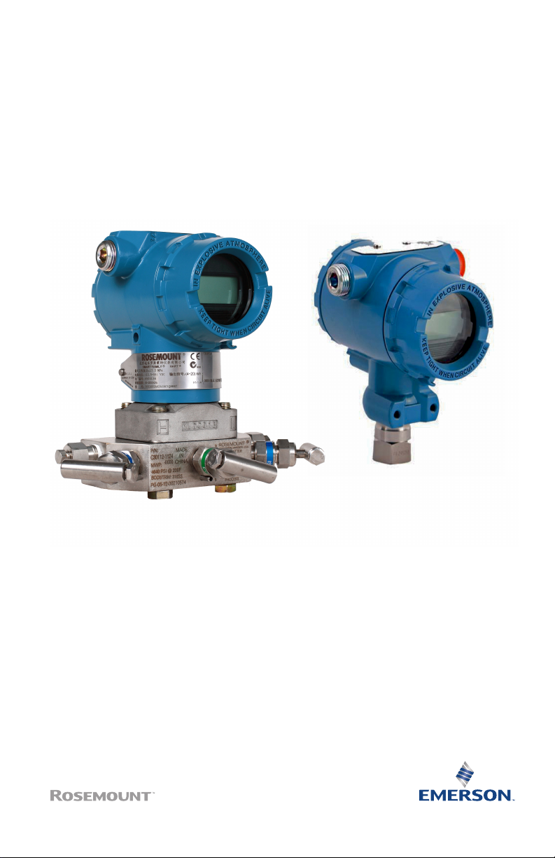
Rosemount™ 3051 Pressure
Transmitter
Quick Start Guide
August2023
Page 2

Quick Start Guide August2023
Contents
About this guide .......................................................................................................................... 3
System readiness......................................................................................................................... 5
Transmitter installation...............................................................................................................7
Safety instrumented systems installation...............................................................................23
Product certifications................................................................................................................ 24
2 Rosemount 3051
Page 3

August2023 Quick Start Guide
1 About this guide
This guide provides basic guidelines for Rosemount 3051 Pressure
Transmitters. It does not provide instructions for configuration,
diagnostics, maintenance, service, troubleshooting, Explosion-proof,
Flameproof, or Intrinsically Safe (IS) installations. Refer to the
Rosemount 3051 Manual for more instructions. This guide is also
available electronically at Emerson.com.
1.1 Safety messages
WARNING
Explosions
Explosions could result in death or serious injury.
Installation of device in an explosive environment must be in
accordance with appropriate local, national, and international
standards, codes, and practices. Review the approvals section of
the Rosemount 3051 Manual for any restrictions associated with a
safe installation.
In an explosionproof/flameproof installation, do not remove the
transmitter covers when power is applied to the transmitter.
WARNING
Process leaks
Process leaks may cause harm or result in death.
To avoid process leaks, only use the O-ring designed to seal with the
corresponding flange adapter.
WARNING
Electrical shock
Electrical shock can result in death or serious injury.
Avoid contact with the leads and terminals. High voltage that may be
present on leads can cause electrical shock.
Quick Start Guide 3
Page 4

Quick Start Guide August2023
WARNING
Conduit/cable entries
Unless otherwise marked, the conduit/cable entries in the
housing enclosure use a ½–14 NPT form. Only use plugs,
adapters, glands, or conduit with a compatible thread form when
closing these entries.
Entries marked M20 are M20 x 1.5 thread form. On devices with
multiple conduit entries, all entries will have the same thread
form.
When installing in a hazardous location, use only appropriately
listed or Ex certified plugs, glands, or adapters in cable/conduit
entries.
WARNING
Physical access
Unauthorized personnel may potentially cause significant damage to
and/or misconfiguration of end users’ equipment. This could be
intentional or unintentional and needs to be protected against.
Physical security is an important part of any security program and
fundamental in protecting your system. Restrict physical access by
unauthorized personnel to protect end users’ assets. This is true for
all systems used within the facility.
4 Rosemount 3051
Page 5

August2023 Quick Start Guide
2 System readiness
Confirm HART® revision capability
• If using HART-based control or asset management systems,
confirm the HART capability of those systems prior to transmitter
installation. Not all systems are capable of communicating with
HART Revision 7. You can configure this transmitter for either
HART Revision 5 or 7.
• For instructions on how to change the HART revision of your
transmitter, see Switch HART® revision mode.
2.1 Confirm correct device driver
• Verify the latest device driver (DD/DTM™) is loaded on your
systems to ensure proper communications.
• Download the latest device driver from Emerson.com or
Fieldcommgroup.org.
Rosemount 3051 device revisions and drivers
Table 2-1 provides the information necessary to ensure you have the
correct device driver and documentation for your device.
Table 2-1: Rosemount 3051 with 4-20 mA HART® protocol device revisions
and files
Release
date
Aug-16 1.1.xx 1.0.xx 3 7 10 with
Jan-13 N/A 1.0.xx 1 7 10
Quick Start Guide 5
Device identification Device driver
NAMUR
hardware
revision
(1)
(1)
HART
software
revision
(2)
identification
HART
universal
revision
5 9
5 9
Device
revision
(3)
Review
instructions
Rosemount
2088,
2090P,
and
2090F
pressure
transmitters
HART
and 1–5
Vdc Low
Power
Protocol
Reference
Manual
Review
function
ality
Change
description
(4)
(5)
Page 6

Quick Start Guide August2023
Table 2-1: Rosemount 3051 with 4-20 mA HART® protocol device revisions
and files
(continued)
Release
date
Device identification Device driver
identification
NAMUR
hardware
revision
(1)
(1)
HART
software
revision
(2)
HART
universal
revision
Device
revision
(3)
Review
instructions
Rosemount
2088,
2090P,
and
Review
function
ality
Change
description
2090F
pressure
transmitters
Jan-98 N/A N/A 178 5 3
N/A
with 4–
20 mA
HART
and 1–5
Vdc Low
Power
Protocol
Reference
Manual
(1) NAMUR revision is located on the hardware tag of the device. Differences in level
3 changes, signified above by xx, represent minor product changes as defined
per NE53. Compatibility and functionality are preserved and product can be used
interchangeably.
(2) HART software revision can be read using a HART capable configuration tool. Value
shown is minimum revision that could correspond to NAMUR revisions.
(3) Device driver file names use Device and DD Revision, (such as 10_01). HART protocol
is designed to enable legacy device driver revisions to continue to communicate
with new HART devices. To access new functionality, download the new device
driver. Emerson recommends downloading new device driver files to ensure full
functionality.
(4) HART revision 5 and 7 selectable, Local Operator Interface (LOI), scaled variable,
configurable alarms, and expanded engineering units.
(5) Rosemount 3051G Pressure Transmitter updated electronics hardware design.
Intrinsic Safety temperature classification change.
6 Rosemount 3051
Page 7
Coplanar In-line
Flow
August2023 Quick Start Guide
3 Transmitter installation
3.1 Mounting the transmitter
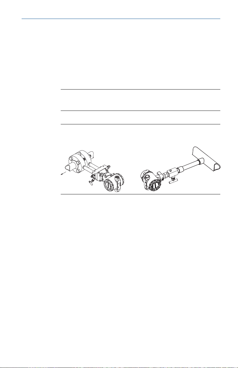
3.1.1 Mount the transmitter in liquid applications
Procedure
1. Place taps to the side of the line.
2. Note
When mount the transmitter, verify the drain/vent valves are
oriented upward.
Mount the transmitter beside or below the taps.
Figure 3-1: Coplanar and in-line liquid applications
Quick Start Guide 7
Page 8
Coplanar
In-line
Flow
Quick Start Guide August2023
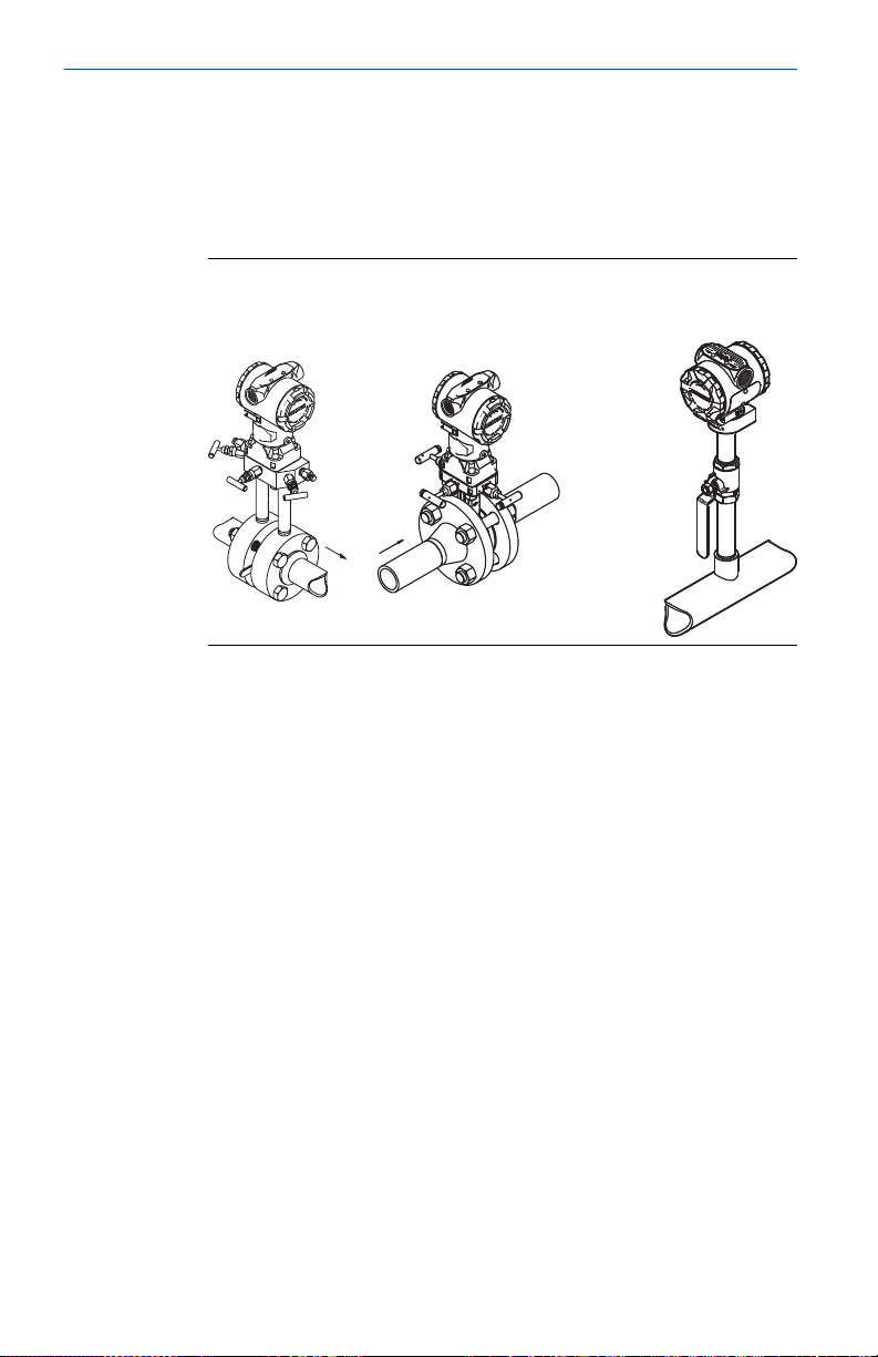
3.1.2 Mount the transmitter in gas applications
Procedure
1. Place taps in the top or side of the line.
2. Mount the transmitter beside or above the taps.
Figure 3-2: Coplanar and in-line gas applications
8 Rosemount 3051
Page 9
Coplanar In-line
Flow
August2023 Quick Start Guide
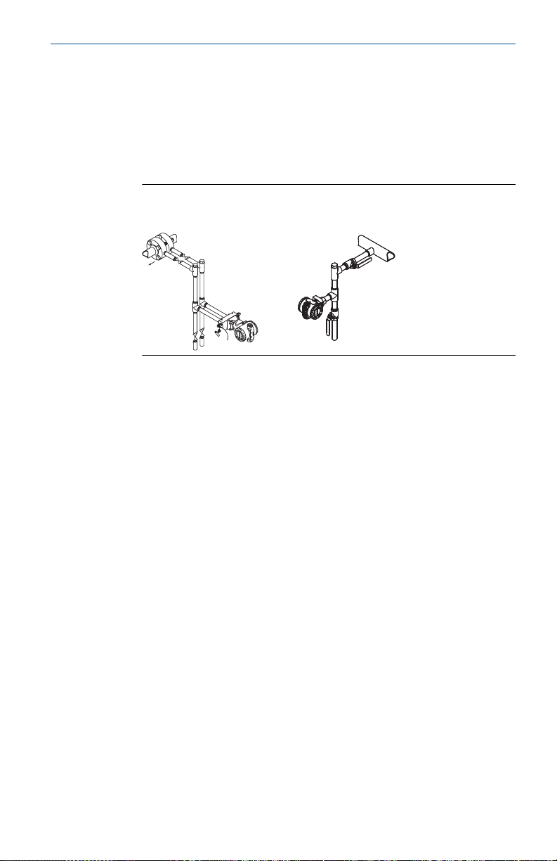
3.1.3 Mount the transmitter in steam applications
Procedure
1. Place taps to the side of the line.
2. Mount the transmitter beside or below the taps.
3. Fill impulse lines with water.
Figure 3-3: Coplanar and in-line steam applications
Quick Start Guide 9
Page 10
Quick Start Guide August2023
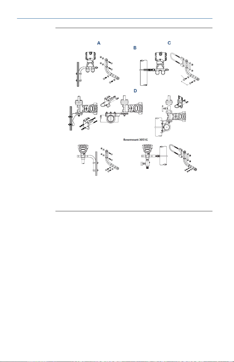
Figure 3-4: Panel and pipe mounting
A. Panel mount (5/6 x 1½ panel bolts are customer supplied
B. Coplanar flange
C. Pipe mount
D. Traditional flange
3.1.4 Assemble the transmitter
If the transmitter installation requires assembly of the process
flanges, manifolds, or flange adapters, follow the assembly
guidelines to ensure a tight seal for optimal performance. Use only
bolts supplied with the transmitter or sold by Emerson as spare
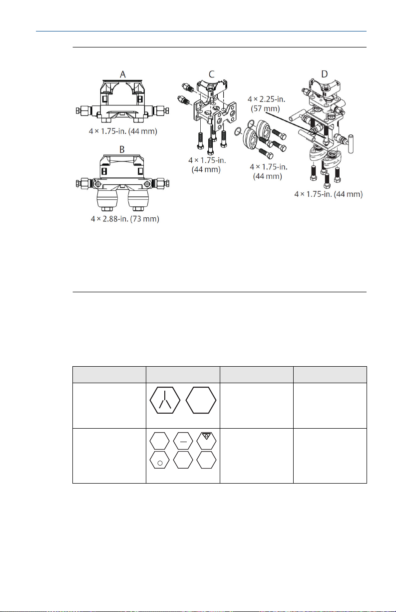
parts. Figure 3-5 illustrates common transmitter assemblies with the
required bolt lengths.
10 Rosemount 3051
Page 11
B7M
316
316
316
SW
316
STM
316
R
B8M
August2023 Quick Start Guide
Figure 3-5: Common transmitter assemblies
A. Transmitter with coplanar flange
B. Transmitter with coplanar flange and optional flange adapters
C. Transmitter with traditional flange and optional flange adapters
D. Transmitter with coplanar flange and optional manifold and
flange adapters
Bolts are typically Carbon Steel (CS) or Stainless Steel (SST). Confirm
the material by viewing the markings on the head of the bolt and
referencing Table 3-1. If bolt material is not shown in Table 3-1,
contact a local Emerson representative for more information.
Table 3-1: Torque values for the flange and flange adapter bolts
Bolt material Head markings Initial torque Final torque
CS
300 in-lb
650 in-lb
SST
150 in-lb 300 in-lb
CS bolts do not require lubrication, and SST bolts are coated with a
lubricant to ease installation. When installing either type of bolt, do
not apply additional lubricant.
Procedure
1. Finger-tighten the bolts.
Quick Start Guide 11
Page 12
A
Quick Start Guide August2023
2. Torque the bolts to the initial torque value using a crossing
pattern.
See Table 3-1 for initial torque value.
3. Torque the bolts to the final torque value using the same
crossing pattern.
See Table 3-1 for final torque value.
4. Before applying pressure, verify that the flange bolts are
protruding through the isolator plate.
3.1.5 In-line gage transmitter orientation
The low side pressure port (atmospheric reference) on the in-line
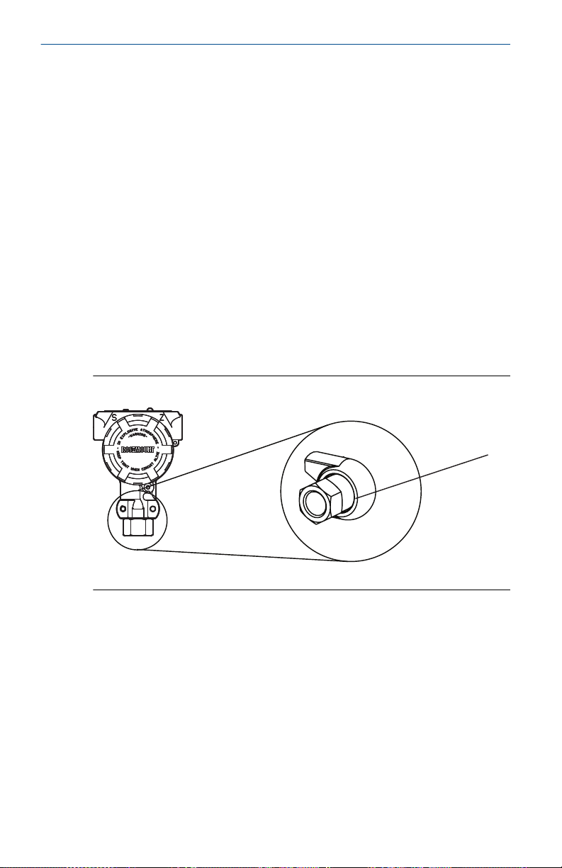
gage transmitter is located in the neck of the transmitter, behind the
housing. The vent path is 360° around the transmitter between the
housing and sensor. (See Figure 3-6)
Mounting the transmitter so that the process can drain away keeps
the vent path free of any obstruction, including but not limited to
paint, dust, and lubrication.
Figure 3-6: In-line Gage Low Side Pressure Port
A. Low side pressure port (atmospheric reference)
12 Rosemount 3051
Page 13
A
August2023 Quick Start Guide
3.1.6 Consider housing rotation
To improve field access to wiring or to better view the optional LCD
display:
Procedure
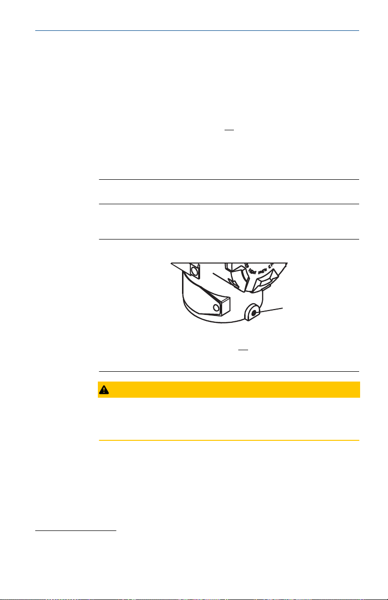
1. Loosen the housing rotation set screw using a
″ hex wrench.
2. Turn the housing left or right maximum up to 180° from its
original position.
(1)
Note
Over-rotating can damage the transmitter.
3. When desired location is reached, re-tighten the housing
rotation set screw to no more than 7in‑lb.
Figure 3-7: Housing Rotation Set Screw
5
64
A. Housing rotation set screw (
5
64
″)
CAUTION
Overrotation of housing may cause damage to module
communication cable.
3.2 Set the switches
Procedure
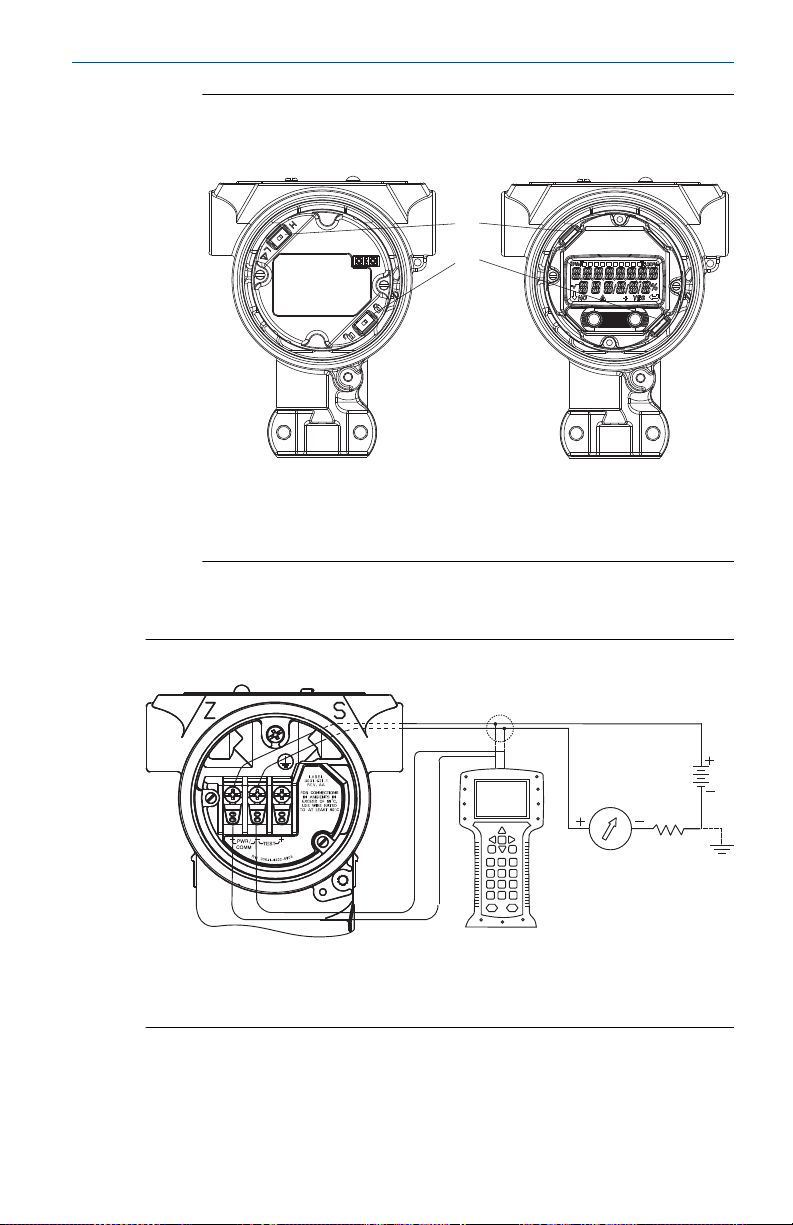
1. Set alarm and security switch configuration before installation
as shown in Figure 3-8.
Rosemount 3051D original position aligns with “H” side; Rosemount 3051G
(1)
original position is the opposite side of bracket holes.
Quick Start Guide 13
Page 14

Quick Start Guide August2023
2. If the transmitter is installed, secure the loop and remove
power.
3. Note
Do not remove the instrument cover in explosive atmospheres
when the circuit is live.
Remove the housing cover opposite the field terminal side.
NOTICE
4.
The alarm switch sets the analog output alarm to High or Low.
Default alarm is High.
NOTICE
The security switch allows (unlocked symbol) or prevents
(locked symbol) any configuration of the transmitter. Default
security is Off (unlocked symbol).
Slide the security and alarm switches into the preferred
position using a small screwdriver.
5. Note
The cover must be fully engaged to comply with explosionproof requirements.
Reattach the transmitter cover.
14 Rosemount 3051
Page 15
A
B
A
B
C
August2023 Quick Start Guide
Figure 3-8: Transmitter Electronics Board
Without LCD display With LCD/LOI display
A. Alarm
B. Security
3.3 Connect the wiring and power up
Figure 3-9: Transmitter Wiring Diagrams (4–20 mA)
A. 24 Vdc supply
B. RL≥ 250
C. Current meter (optional)
Shielded twisted pair cable should be used for best results. Use 24
AWG or larger wire that does not exceed 5,000 ft. (1500 m) in length.
If applicable, install wiring with a drip loop. Arrange the drip loop so
Quick Start Guide 15
Page 16

Quick Start Guide August2023
the bottom is lower than the conduit connections and the transmitter
housing.
CAUTION
Installation of the transient protection terminal block does not
provide transient protection unless the Rosemount 3051 case is
properly grounded.
Do not run signal wiring in conduit or open trays with power wiring,
or near heavy electrical equipment.
Do not connect the powered signal wiring to the test terminals.
Power could damage the test diode in the terminal block.
To wire the transmitter:
Procedure
1. Remove the housing cover on the FIELD TERMINALS side.
2. Connect the positive lead to the “+” terminal (PWR/COMM) and
the negative lead to the “–” terminal.
3. Ground housing to fulfill local grounding regulations.
4. Ensure proper grounding. It is important that the instrument
cable shield be:
a) Trimmed close and insulated from touching the
transmitter housing
b) Connected to the next shield if cable is routed through
a junction box
c) Connected to a good earth ground at the power supply
end
5. If transient protection is needed, refer to "Grounding for
transient terminal block" for grounding instructions.
6. Plug and seal unused conduit connections.
7. Replace the housing cover.
16 Rosemount 3051
Page 17
DP
A
B
C
August2023 Quick Start Guide
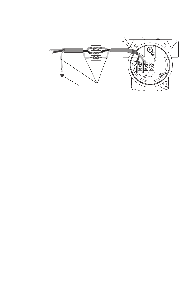
Figure 3-10: Wiring
A. Insulate shield and shield drain wire.
B. Insulate exposed shield drain wire.
C. Connect shield back to the power supply ground.
3.3 Grounding for transient terminal block
Ground termination is provided on the outside of the electronics
housing and inside the terminal compartment. These grounds are
used when the transient protection terminal blocks are installed. It is
recommended that 18 AWG or larger wire is used to connect housing
ground to earth ground (internal or external).
If the transmitter is currently not wired for power up and
communication, follow Connect the wiring and power up. When the
transmitter is properly wired, refer to Figure 3-10 for internal and
external transient grounding locations.
3.4
Verifying configuration
Verify the configuration using any HART®-capable configuration tool.
Configuration instructions for a Field Communicator are included in
this step. See Rosemount 3051 Reference Manual for configuration
instructions using AMS Device Manager.
3.4.1 Verifying configuration with a Field Communicator
A Rosemount 3051 DD must be installed on the Field Communicator
to verify configuration. Fast Key sequences for the latest DD are
shown in Table 2-2. For Fast Key sequences using legacy DD's,
contact your local Emerson representative.
Quick Start Guide 17
Page 18
Quick Start Guide August2023
Note
Emerson recommends installing the latest DD to access the complete
functionality. Visit Field Communicator for information on updating
the DD library.
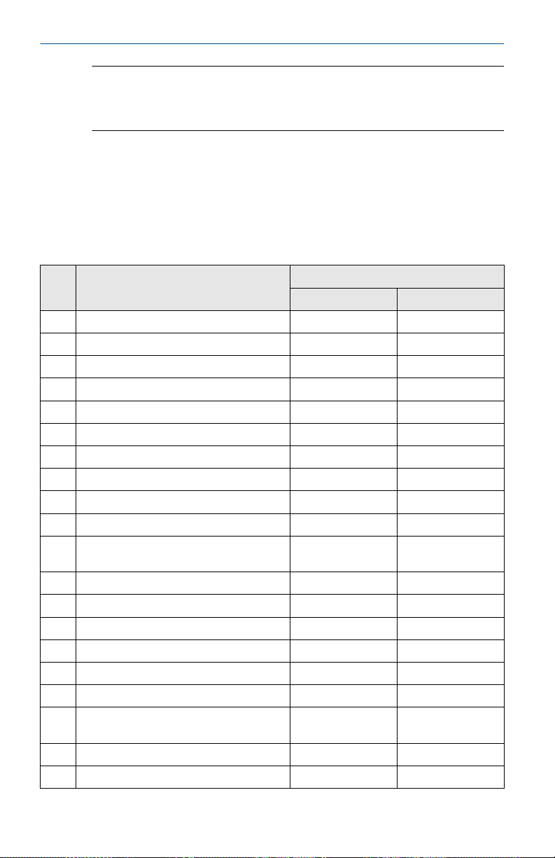
Procedure
Verify device configuration using the Fast Key sequences in Table 2-2.
• A check (✓) indicates the basic configuration parameters. At
minimum, these parameters should be verified as part of
configuration and startup.
• A (7) indicates availability only in HART® Revision 7 mode.
Function Fast Key sequence
HART® 7 HART 5
✓ Alarm and Saturation Levels 2, 2, 2, 5, 7 2, 2, 2, 5, 7
✓ Damping 2, 2, 1, 1, 5 2, 2, 1, 1, 5
✓ Range Values 2, 2, 2, 2, 2, 2
✓ Tag 2, 2, 7, 1, 1 2, 2, 7, 1, 1
✓ Transfer Function 2, 2, 1, 1, 6 2, 2, 1, 1, 6
✓ Units 2, 2, 1, 1, 4 2, 2, 1, 1, 4
Burst Mode 2, 2, 5, 3 2, 2, 5, 3
Custom Display Configuration 2, 2, 4 2, 2, 4
Date 2, 2, 7, 1, 4 2, 2, 7, 1, 3
Descriptor 2, 2, 7, 1, 5 2, 2, 7, 1, 4
Digital to Analog Trim (4–20 mA
output)
Disable Configuration Buttons 2, 2, 6, 3 2, 2, 6, 3
Rerange with Keypad 2, 2, 2, 1 2, 2, 2, 1
Loop Test 3, 5, 1 3, 5, 1
Lower Sensor Trim 3, 4, 1, 2 3, 4, 1, 2
Message 2, 2, 7, 1, 6 2, 2, 7, 1, 5
Scaled D/A Trim (4–20 mA output) 3, 4, 2 3, 4, 2
Sensor Temperature/Trend
(Rosemount 3051S)
Upper Sensor Trim 3, 4, 1, 1 3, 4, 1, 1
Digital Zero Trim 3, 4, 1, 3 3, 4, 1, 3
3, 4, 2 3, 4, 2
3, 3, 3 3, 3, 3
18 Rosemount 3051
Page 19
A
B
August2023 Quick Start Guide
Function Fast Key sequence
HART® 7 HART 5
Password 2, 2, 6, 5 2, 2, 6, 4
Scaled Variable 3, 2, 2 3, 2, 2
HART revision 5 to HART Revision 7
switch
✓ Long Tag 2, 2, 7, 1, 2 N/A
✓ Find Device 3, 4, 5 N/A
✓ Simulate Digital Signal 3, 4, 5 N/A
2, 2, 5, 2, 3 2, 2, 5, 2, 3
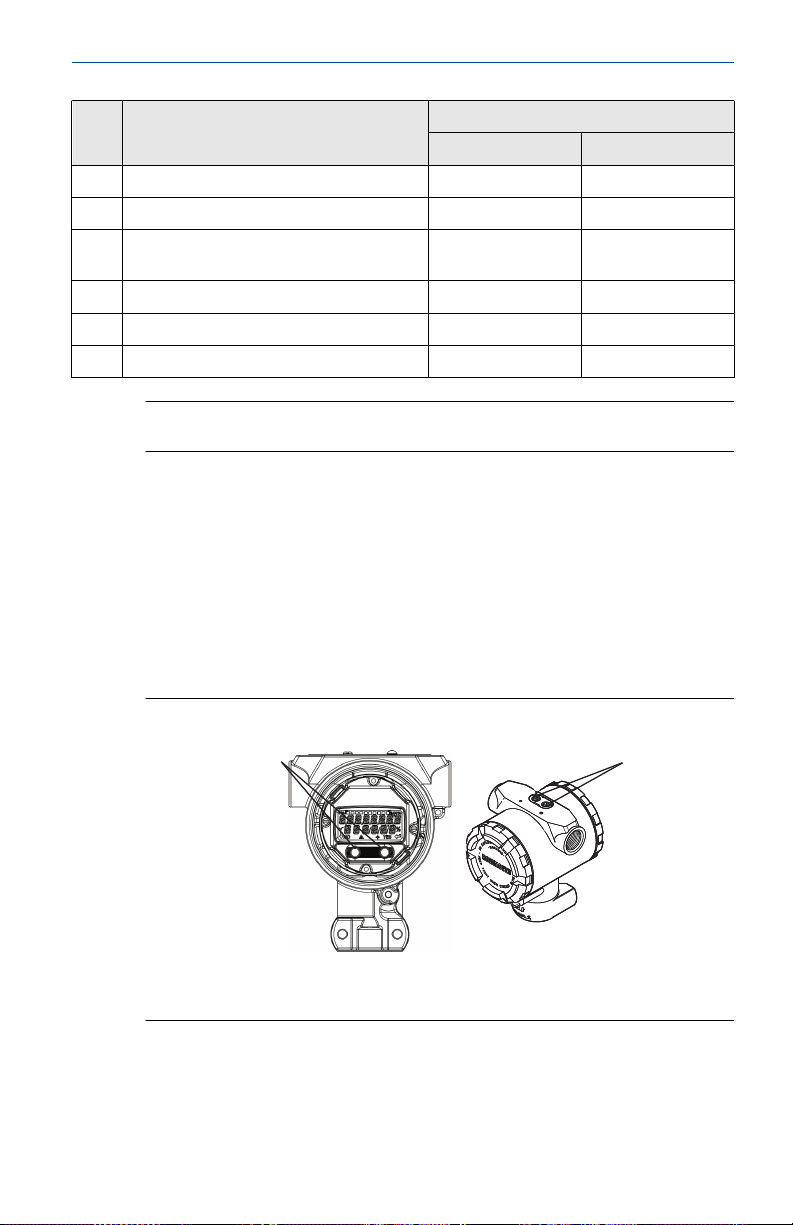
Note
See Figure 3-10 to confirm external button functionality.
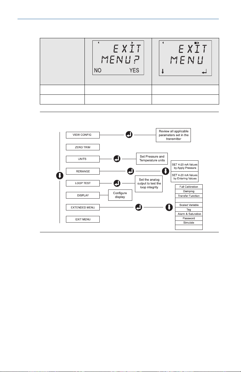
3.4.2 Verify configuration with local operator interface (LOI)
The optional local operator interface (LOI) can be used for
commissioning the device. The LOI is a two button design with
internal and external buttons. The internal buttons are located on
the display of the transmitter, while the external buttons are located
underneath the top metal tag. LOI button functionality is shown on
the bottom corners of the display.
To activate the LOI, push any button. See Table 3-2 and Figure 3-12
for button operation and menu information.
Figure 3-11: Internal and External LOI Buttons
A. Internal buttons
B. External buttons
Quick Start Guide 19
Page 20
Assign PV
HART Revision
Quick Start Guide August2023
Table 3-2: LOI Button Operation
Button
Left No SCROLL
Right Yes ENTER
Figure 3-12: LOI Menu
3.4.3 Switch HART® revision mode
If the HART configuration tool is not capable of communicating with
HART Revision 7, the Rosemount 3051 will load a generic menu with
limited capability. The following procedures will switch the HART
revision mode from the generic menu:
Procedure
Manual Setup → Device Information → Identification → Message
a) To change to HART Revision 5, Enter: “HART5” in the Message
field
b) To change to HART Revision 7, Enter: “HART7” in the Message
field
20 Rosemount 3051
Page 21

August2023 Quick Start Guide
3.5 Trim the transmitter
Devices are calibrated by the factory. Once installed, it is
recommended to perform a zero trim on gage and differential
pressure transmitters to eliminate error due to mounting position
or static pressure effects. A zero trim can be performed using either a
Field Communicator or configuration buttons.
For instructions using AMS Device Manager, see the Rosemount 3051
Reference Manual.
Note
When performing a zero trim, ensure that the equalization valve is
open and all wet legs are filled to the correct level.
Procedure
1. Choose your trim procedure.
• Analog zero trim – Sets the analog output to 4 mA.
2. Also referred to as a “rerange,” it sets the lower range value
(LRV) equal to the measured pressure.
3. The display and digital HART output remains unchanged.
• Digital zero trim – Recalibrates the sensor zero.
4. The LRV is unaffected. The pressure value will be zero (on
display and HART® output). 4 mA point may not be at zero.
5. This requires that the factory calibrated zero pressure is within
a range of 3% of the URV [0 + 3% x URV].
Example: URV = 250 inH2O Applied Zero Pressure = + 0.03 x
250 inH2O = + 7.5 inH2O (compared to factory settings) values
outside this range will be rejected by the transmitter.
3.5.1 Trimming with a Field Communicator
Procedure
1. Connect the Field Communicator. See "Connect the wiring and
power up" for instructions.
2. Follow the HART® menu to perform the desired zero trim.
Table 3-3: Zero Trim Fast Keys
Analog zero (Set 4 mA) Digital zero
Fast Key sequence 3, 4, 2 3, 4, 1, 3
Quick Start Guide 21
Page 22
A
B C
D
Quick Start Guide August2023
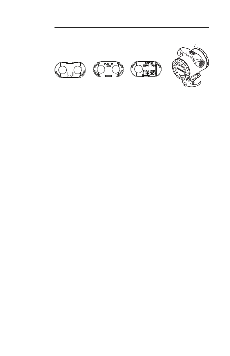
Figure 3-13: External Configuration Buttons
A. LOI
B. Analog zero and span
C. Digital zero
D. Configuration buttons
Perform trim with LOI (option M4) for a zero trim.
3. Set the transmitter pressure.
4. See Figure 3-12 for the operating menu.
a) Perform an analog zero trim by selecting Rerange.
b) Perform a digital zero trim by selecting Zero Trim.
22 Rosemount 3051
Page 23

August2023 Quick Start Guide
4 Safety instrumented systems installation
For safety certified installations, refer to the Rosemount
3051 Reference Manual for installation procedure and system
requirements.
Quick Start Guide 23
Page 24
Quick Start Guide August2023
5 Product certifications
5.1 Rosemount 3051D Pressure Transmitter
Rev 3.10
5.1.1 European Directive information
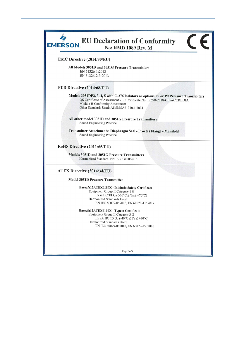
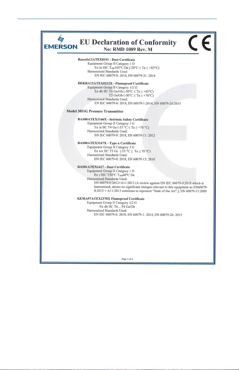
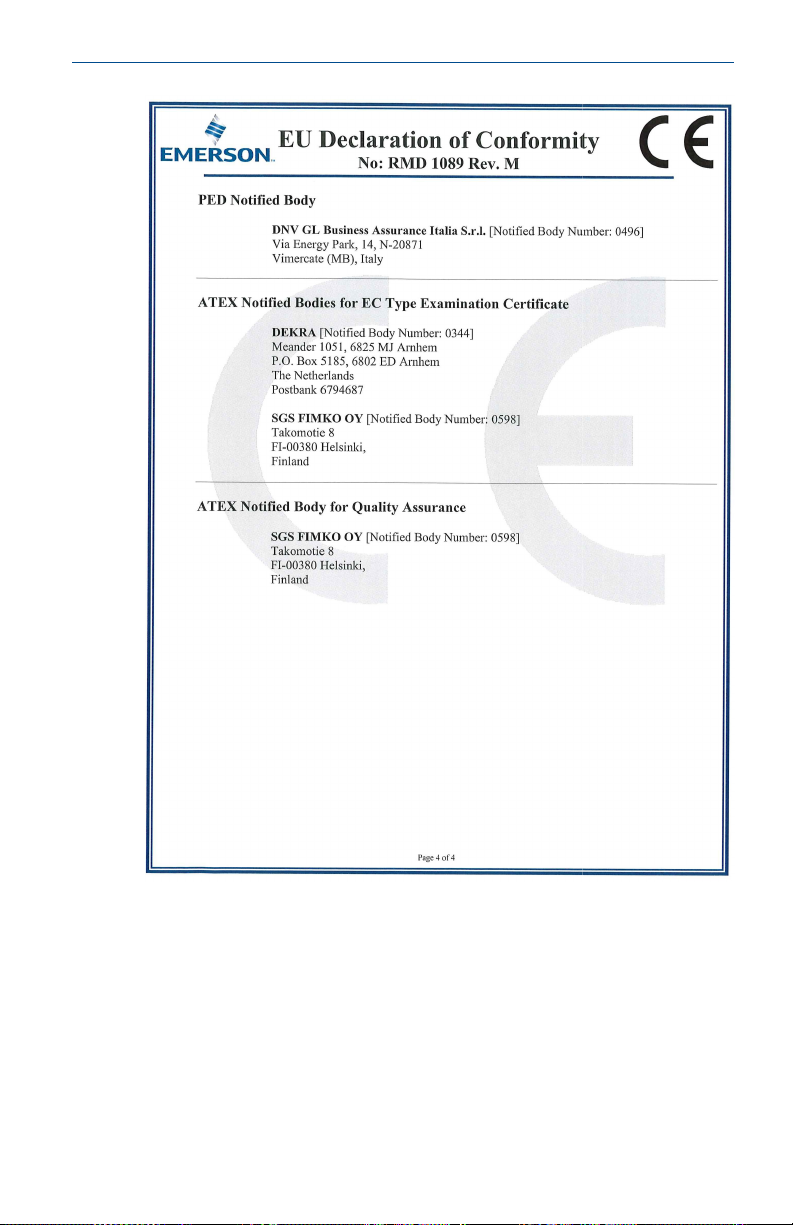
A copy of the EU Declaration of Conformity can be found at the
end of the Quick Start Guide. The most recent revision of the EU
Declaration of Conformity can be found at Emerson.com.
5.1.2 Europe
E8 ATEX Flameproof and Dust
Certificate
Standards
DEKRA12ATEX0212X (Ex d); Baseefa12ATEX0191 (Ex ta)
EN IEC 60079-0: 2018, EN60079-1: 2014, EN60079-26:
2015, EN60079-31: 2014
Markings
II 1/2 G Ex db IIC T6...T4 Ga/Gb, T6 (–60 °C ≤ Ta ≤ +70
°C), T5/T4 (–60 °C ≤ Ta ≤ +80 °C)
II 1 D Ex ta IIIC T
V
= 42.4Vdc
max
105 °C Da (–20 °C ≤ Ta ≤ +85 °C)
200
Table 5-1: Process temperature
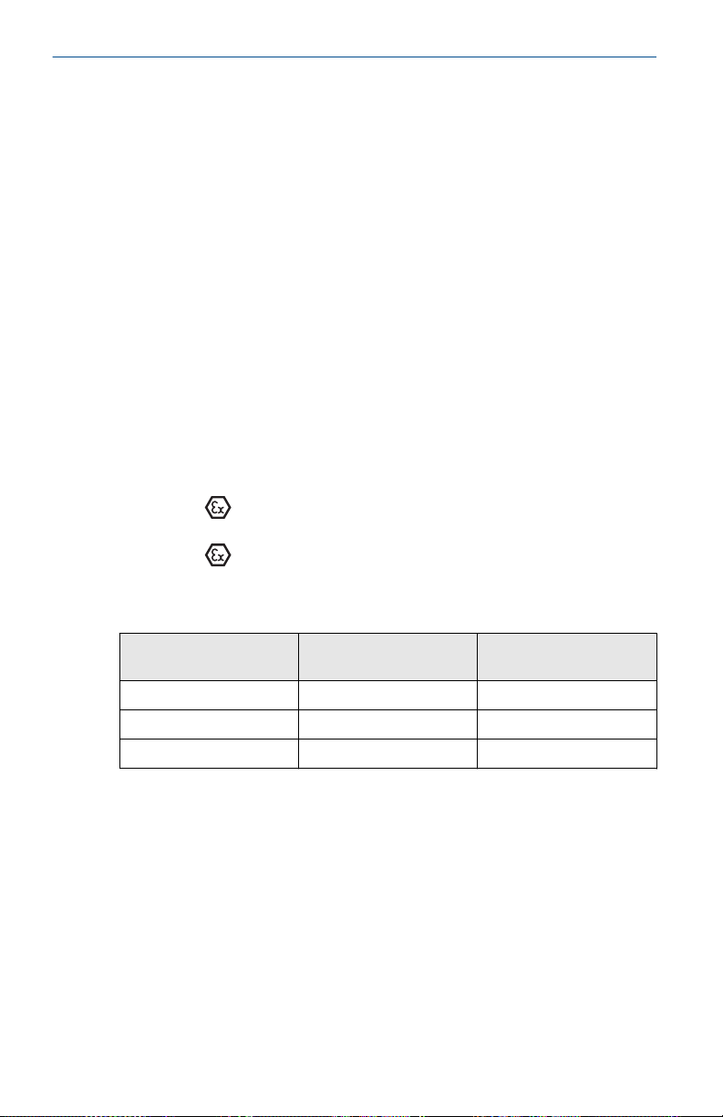
Temperature class Process connection
temperature
T6 –60 to +70 °C –60 to +70 °C
T5 –60 to +80 °C –60 to +80 °C
T4 –60 to +120 °C –60 to +80 °C
Ambient temperature
Special Conditions for Safe Use (X):
1. This device contains a thin wall diaphragm less than 1 mm
thickness that forms a boundary between Category 1 (process
connection) and Category 2 (all other parts of the equipment).
The model code and datasheet are to be consulted for details
of the diaphragm material. Installation, maintenance and
use shall take into account the environmental conditions to
which the diaphragm will be subjected. The manufacturer's
instructions for installation and maintenance shall be followed
in detail to assure safety during its expected lifetime.
2. Flameproof joints are not intended for repair.
24 Rosemount 3051
Page 25
August2023 Quick Start Guide
3. Non-standard paint options may cause risk from electrostatic
discharge. Avoid installations that could cause electrostatic
build-up on painted surfaces and only clean the painted
surfaces with a damp cloth. If paint is ordered through
a special option code, contact the manufacturer for more
information.
4. Some variants of the equipment have reduced markings on
the nameplate. Refer to the Certificate for full equipment
marking.
5. Appropriate cable, glands, and plugs need to be suitable
for a temperature of 5 °C greater than maximum specified
temperature for location where installed.
I1 ATEX Intrinsic Safety and Dust
Certificate
Standards:
Baseefa12ATEX0189X; Baseefa12ATEX0191
EN IEC 60079-0: 2018, EN60079-11: 2012, EN 60079-31:
2014
Markings:
II 1 G Ex ia IIC T4 Ga (–60 °C ≤ Ta≤ +70 °C), II 1 D
Ex ta IIIC T
105 °C Da (–20 °C ≤ Ta≤ +85 °C)
200
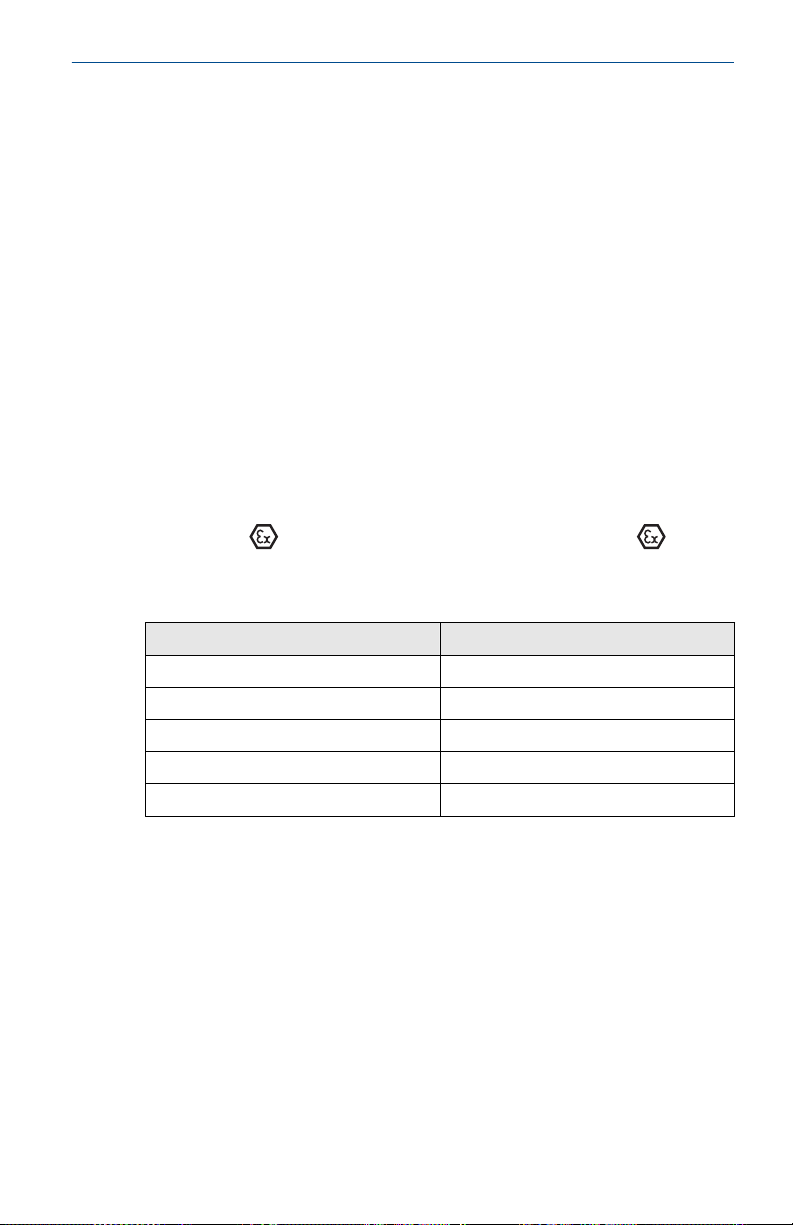
Table 5-2: Input parameters
Parameters HART
Voltage U
Current I
Power P
Capacitance C
Inductance L
i
i
i
i
i
®
30 V
200 mA
1.0 W
0.012 µF
0 mH
Special Conditions for Safe Use (X):
1. The equipment is not capable of withstanding the 500 V
insulation test required by clause 6.3.13 of EN60079-11:
2012. This must be taken into account when installing the
equipment.
2. The enclosure may be made of aluminum alloy and given a
protective polyurethane paint finish; however, care should be
taken to protect it from impact or abrasion if located in Zone 0.
3. Some variants of the equipment have reduced markings on
the nameplate. Refer to the Certificate for full equipment
marking.
Quick Start Guide 25
Page 26

Quick Start Guide August2023
N1 ATEX Type n and Dust
Certificate
Standards
Baseefa12ATEX0190X; Baseefa12ATEX0191
EN IEC 60079-0:2018, EN60079-15:2010, EN
60079-31:2014
Markings
Ex ta IIIC T
Special Conditions for Safe Use (X):
1. The equipment is not capable of withstanding the 500
V insulation test required by clause 6.5.1 of EN60079-15:
2010. This must be taken into account when installing the
equipment.
2. Some variants of the equipment have reduced markings on
the nameplate. Refer to the Certificate for full equipment
marking.
5.1.3 International
E7 IECEx Flameproof and Dust
Certificate
Standards
Markings
IECEx DEK 12.0067X (Ex d); IECEx BAS 12.0109 (Ex ta)
IEC 60079-0: 2017, IEC60079-1: 2014, IEC60079-26: 2014,
IEC 60079-31: 2013
Ex db IIC T6...T4 Ga/Gb, T6 (–60 °C ≤ Ta ≤ +70 °C), T5/T4
(–60 °C ≤ Ta ≤ +80 °C)
Ex ta IIIC T
II 3 G Ex nA IIC T5 Gc (–40 °C ≤ Ta ≤ +70 °C), II 1 D
105 °C Da (–20 °C ≤ Ta ≤ +85 °C)
200
105 °C Da (–20 °C ≤ Ta ≤ +85 °C)
200
Table 5-3: Process temperature
Temperature class Process connection
temperature
T6 –60 to +70 °C –60 to +70 °C
T5 –60 to +80 °C –60 to +80 °C
T4 –60 to +120 °C –60 to +80 °C
Ambient temperature
Special Conditions for Safe Use (X):
1. This device contains a thin wall diaphragm with less than 1
mm thickness that forms a boundary between zone 0 (process
connection) and zone 1 (all other parts of the equipment).
The model code and datasheet are to be consulted for details
of the diaphragm material. Installation, maintenance, and
use shall take into account the environmental conditions to
26 Rosemount 3051
Page 27

August2023 Quick Start Guide
which the diaphragm will be subjected. The manufacturer's
instructions for installation and maintenance shall be followed
in detail to assure safety during its expected lifetime.
2. Flameproof joints are not intended for repair.
3. Some variants of the equipment have reduced markings on
the nameplate. Refer to the Certificate for full equipment
marking.
4. Appropriate cable, glands and plugs need to be suitable
for a temperature of 5 °C greater than maximum specified
temperature for location where installed.
I7 IECEx Intrinsic Safety
Certificate
Standards
Markings
IECEx BAS 12.0107X
IEC 60079-0: 2017, IEC60079-11: 2011
Ex ia IIC T4 Ga (–60 °C ≤ Ta ≤ +70 °C)
Table 5-4: Input parameters
Parameters HART
Voltage U
Current I
Power P
Capacitance C
Inductance L
i
i
i
i
i
®
30 V
200 mA
1.0 W
0.012 µF
0 mH
Special Conditions for Safe Use (X):
1. The equipment is not capable of withstanding the 500 V
insulation test required by clause 6.3.13 of IEC60079-11: 2011.
This must be taken into account when installing the apparatus.
2. The enclosure may be made of aluminum alloy and given a
protective polyurethane paint finish; however, care should be
taken to protect it from impact or abrasion if located in Zone 0.
N7 IECEx Type n
Certificate
Standards
Markings
Quick Start Guide 27
IECEx BAS 12.0108X
IEC 60079-0: 2017, IEC60079-15: 2010
Ex nA IIC T5 Gc (–40 °C ≤ Ta ≤ +70 °C)
Page 28

Quick Start Guide August2023
Special Condition for Safe Use (X):
1. The apparatus is not capable of withstanding the 500 V
insulation test required by IEC60079-15. This must be taken
into account when installing the apparatus.
5.1.4 China
E3 China Flameproof
Certificate
Standards
GYJ22.3617X
GB/T3836.1-2021, GB/T3836.2-2021, GB3836.20-2010,
GB/T 3836.31-2021
Markings
Ex db IIC T6···T4 Ga/Gb,Ex ta IIIC
I3 China Intrinsic Safety
Certificate
Standards
Markings
N3 China Type n
Certificate
Standards
Markings
5.1.5 Combinations
K7
K8
Combination of E7, I7, and N7
Combination of E8, I1, and N1
105 °C Da
T200
GYJ22.3375X
GB3836.1-2021, GB/T3836.4-2021
Ex ia IIC T4 Ga
GYJ23.1148X
GB/T 3836.1-2021,GB/T 3836.-2021
Ex ec IIC T5 Gc
28 Rosemount 3051
Page 29

August2023 Quick Start Guide
5.2 Rosemount 3051G Pressure Transmitter
5.2.1 European Directive information
A copy of the EU Declaration of Conformity can be found at the
end of the Quick Start Guide. The most recent revision of the EU
Declaration of Conformity can be found at Emerson.com.
5.2.2 Ordinary Certification Location
As standard, the transmitter has been examined and tested to
determine that the design meets the basic electrical, mechanical,
and fire protection requirements by a nationally recognized test
laboratory (NRTL) as accredited by the Federal Occupational Safety
and Health Administration (OSHA).
5.2.3 North America
E5 USA Explosionproof (XP) and Dust Ignition-proof (DIP)
Certificate
Standards
Markings
Specific Conditions for Use:
1. The Rosemount 3051 Transmitter housing contains aluminum
2. Equipment evaluated for atmospheric pressure range between
3. Process temperature limits shall be in accordance with
4. Flameproof joints are not intended for repair.
I5 USA Intrinsic Safety (IS) and Nonincendive (NI)
1053834
FM 3600: 2022, FM 3610: 2021, FM 3615: 2022, FM
3616: 2022, ANSI/UL 61010-1-2019 Third Edition, ANSIISA-12.27.01–2022, ANSI/UL 50E (First Edition)
XP: CL I, DIV 1, GP B, C, D T5;
SEAL NOT REQUIRED
DIP: CL II, DIV 1, GP E, F, G; CL III T5;
–50 °C ≤ Ta ≤ +85 °C
TYPE 4X IP 68
OPTIONAL SINGLE SEAL
and is considered a potential risk of ignition by impact or
friction. Care must be taken into account during installation
and use to prevent impact and friction.
80 kPa (0,8 bar) to 110 kPa (1,1 bar).
03031-1053.
Certificate
Quick Start Guide 29
1053834
Page 30

Quick Start Guide August2023
Standards
FM 3600: 2022, FM 3610: 2018, FM 3611: 2021,
ANSI/UL 61010-1-2019 Third Edition, ANSI/UL 60079-0:
2017, ANSI/UL 60079-11: 2013, ANSI-ISA-12.27.01–2022,
ANSI/UL 50E (First Edition)
Markings
IS: CL I GP ABCD T4
IS: CL II GP EFG CL III T4
CL I ZN 0 AEx ia IIC T4 Ga
NI: CL 1 DIV 2 GP ABCD T4
-60 °C ≤ Ta ≤ +70 °C
OPTIONAL SINGLE SEAL
TYPE 4X IP 68
INSTALL PER 03031-1024
Specific Conditions for Use:
1. The Rosemount 3051G transmitter housing may contain
aluminum and is considered a potential risk of ignition by
impact or friction. Care must be taken into account during
installation and use to prevent impact and friction.
2. The Rosemount 3051G with the transient terminal block
(option code T1) will not pass the 500 Vrms dielectric strength
test; this must be taken into account during installation.
3. Equipment evaluated for atmospheric pressure range between
80 kPa (0,8 bar) to 110 kPa (1,1 bar).
4. Maximum process temperature limits shall be in accordance
with 03031-1053.
C6 Canada Explosionproof, Dust Ignition-proof, Intrinsic Safety,
and Division 2
Certificate
Standards
1053834
CAN/CSA C22.2 No. 61010-1-12, CAN/CSA C22.2 No.
94.2-20, CSA C22.2 No. 25-17, CAN/CSA C22.2 No.
30:20, CAN/CSA C22.2 No. 213-17 +UPD1 (2018)+UPD2
(2019)+UPD3 (2021), CAN/CSA C22.2 No. 60079-0:19,
CAN/CSA C22.2 No. 60079-1:16, CAN/CSA-60079-11:14,
ANSI-ISA-12.27.01–202
Markings
XP: CL I DIV 1 GP B, C, D T5
Ex db IIC T5 Gb
SEAL NOT REQUIRED
DIP: CL II, DIV 1, GP E, F, G; CL III T5;
30 Rosemount 3051
Page 31

August2023 Quick Start Guide
T5: -50 °C ≤ Ta ≤ 85 °C
IS: CL I GP ABCD T4
IS: CL II GP EFG, CL III T4
Ex ia IIC T4 Ga
NI: CL I DIV 2 GP ABCD T4
T4: -60 °C ≤ Ta ≤ +70 °C
INSTALL PER 03031-1024 (IS/NI ONLY)
SINGLE SEAL - TEMP LIMITS PER 03031-1053
TYPE 4X, IP 68
Specific Conditions for Use:
1. The Rosemount 3051 Transmitter housing contains aluminum
and is considered a potential risk of ignition by impact or
friction. Care must be taken into account during installation
and use to prevent impact and friction.
2. Equipment evaluated for atmospheric pressure range between
80 kPa (0,8 bar) to 110 kPa (1,1 bar).
3. The Rosemount 3051 Transmitter with the transient terminal
block (Option code T1) will not pass the 500 Vrms dielectric
strength test, and this must be taken into account during
installation.
4. Flameproof joints are not intended for repair.
E6 Canada Explosionproof, Dust Ignition-proof, and Division 2
Certificate
Standards
1053834
CAN/CSA C22.2 No. 61010-1-12, CAN/CSA C22.2 No.
94.2-20, CSA C22.2 No. 25-17, CAN/CSA C22.2 No.
30:20, CAN/CSA C22.2 No. 213-17 +UPD1 (2018)+UPD2
(2019)+UPD3 (2021), CAN/CSA C22.2 No. 60079-0:19,
CAN/CSA C22.2 No. 60079-1:16, ANSI-ISA-12.27.01–2021
Markings
XP: CL 1, DIV 1, GP B, C, D T5
Ex db IIC T5 Gb
SEAL NOT REQUIRED
DIP: CL II, DIV 1, GP E, F, G, CL III T5
T5: -50 °C ≤ Ta ≤ +85 °C
NI: CL I DIV 2 GP ABCD T4
T4: -60 °C ≤ Ta ≤ +70 °C
SINGLE SEAL - TEMP LIMITS PER 03031-1053
TYPE 4X, IP 68
Quick Start Guide 31
Page 32
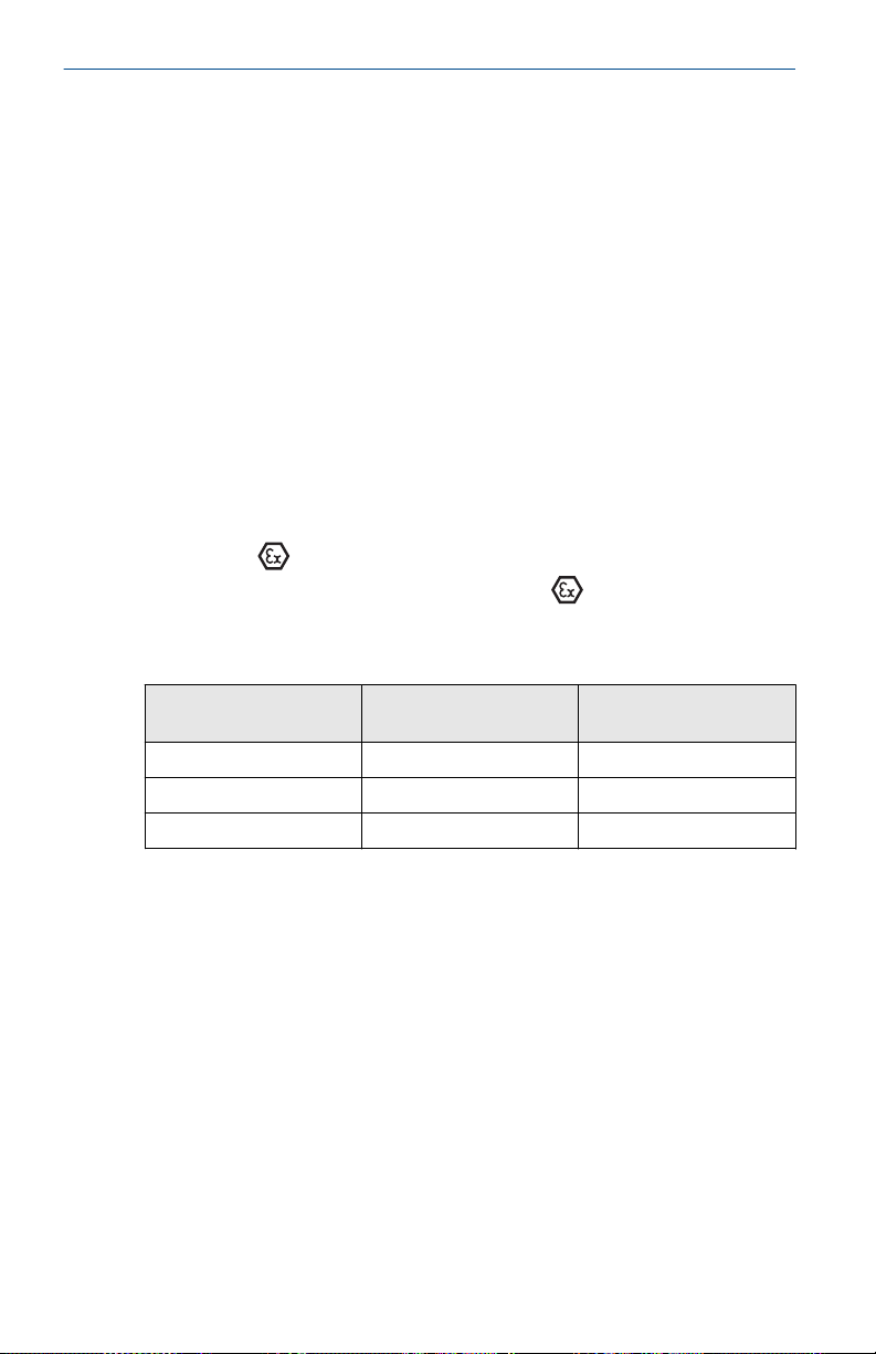
Quick Start Guide August2023
Specific Conditions for Use:
1. The Rosemount 3051 Transmitter housing contains aluminum
and is considered a potential risk of ignition by impact or
friction. Care must be taken into account during installation
and use to prevent impact and friction.
2. Equipment evaluated for atmospheric pressure range between
80 kPa (0,8 bar) to 110 kPa (1,1 bar).
3. Flameproof joints are not intended for repair.
5.2.4 Europe
E8 ATEX Flameproof and Dust
Certificate
Standards
KEMA97ATEX2378X; BAS01ATEX1427X
EN60079-0:2012 + A11: 2013, EN60079-1: 2013,
EN60079-26: 2015, EN60079-31: 2009
Markings
II 1/2 G Ex db IIC T6…T4 Ga/Gb, T6 (–60 °C ≤ Ta ≤ +70
°C), T5/T4 (–60 °C ≤ Ta ≤ +80 °C); II 1 D Ex t IIIC T50 °C
T
60 °C Da
500
Table 5-5: Process connection temperature
Temperature class Process connection
temperature
T6 –60 to +70 °C –60 to +70 °C
T5 –60 to +80 °C –60 to +80 °C
T4 –50 to +120 °C –60 to +80 °C
Ambient temperature
Special Conditions for Safe Use (X):
1. This device contains a thin wall diaphragm with less than 1
mm thickness that forms a boundary between zone 0 (process
connection) and zone 1 (all other parts of the equipment).
The model code and datasheet are to be consulted for details
of the diaphragm material. Installation, maintenance, and
use shall take into account the environmental conditions to
which the diaphragm will be subjected. The manufacturer's
instructions for installation and maintenance shall be followed
in detail to assure safety during its expected lifetime.
2. Flameproof joints are not intended for repair.
3. Non-standard paint options may cause risk from electrostatic
discharge. Avoid installations that could cause electrostatic
32 Rosemount 3051
Page 33

August2023 Quick Start Guide
build-up on painted surfaces and only clean the painted
surfaces with a damp cloth. If paint is ordered through
a special option code, contact the manufacturer for more
information.
4. Appropriate cable, glands, and plugs need to be suitable
for a temperature of 5 °C greater than maximum specified
temperature for location where installed.
5. The user must ensure that the maximum rated voltage and
current (36 volts, 24 milliamps, d.c.) are not exceeded. All
connections to other apparatus or associated apparatus shall
have control over this voltage and current equivalent to a
category 'ib' circuit according to EN 50020.
6. Cable entries must be used which maintain the ingress
protection of the enclosure to at least IP66.
7. Unused cable entries must be filled with suitable blanking
plugs which maintain the ingress protection of the enclosure
to at least IP66.
8. Cable entries and blanking plugs must be suitable for the
ambient range of the apparatus and capable of withstanding a
7J impact test.
9. Rosemount 2088/2090 sensor module must be securely
screwed in place to maintain the ingress protection of the
enclosure.
10. Some variants of the equipment have reduced markings on
the nameplate. Refer to the Certificate for full equipment
marking.
I1 ATEX Intrinsic Safety and Dust
Certificate
Standards
Markings
BAS00ATEX1166X
EN60079-0: 2012+A11: 2013, EN60079-11: 2012
II 1 G Ex ia IIC T4 Ga (–55 °C ≤ Ta ≤ +70 °C)
Table 5-6: Input parameters
Parameters HART
Voltage U
Current I
Power P
Capacitance C
Quick Start Guide 33
i
i
i
i
®
30 V
200 mA
0.9 W
0.012 µF
Page 34
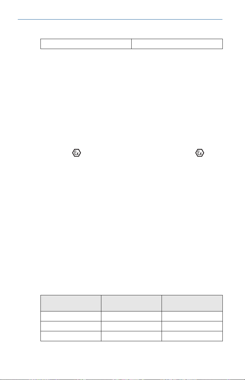
Quick Start Guide August2023
Table 5-6: Input parameters
Inductance L
i
(continued)
0 mH
Special Conditions for Safe Use (X):
1. When fitted with a transient suppression terminal block, the
equipment is not capable of withstanding the 500 V insulation
test. This must be taken into account during installation.
2. The enclosure may be made of aluminum alloy and given a
protective polyurethane paint finish; however, care should be
taken to protect it from impact or abrasion if located in Zone 0.
N1 ATEX Type n and Dust
Certificate
Standards
Markings
BAS00ATEX3167X; BAS01ATEX1427X
EN60079-0: 2012, EN60079-15: 2010, EN60079-31: 2009
II 3 G Ex nA IIC T5 Gc (–40 °C ≤ Ta ≤ +70 °C); II 1 D
Ex t IIIC T50 °C T
60 °C Da
500
Special Conditions for Safe Use (X):
1. This apparatus is not capable of withstanding the 500 V
insulation test that is required by EN60079-15. This must be
taken into account when installing the apparatus.
2. Some variants of the equipment have reduced markings on
the nameplate. Refer to the Certificate for full equipment
marking.
5.2.5 International
E7 IECEx Flameproof
Certificate
Standards
Markings
Temperature class Process connection
T6 –60 to +70 °C –60 to +70 °C
T5 –60 to +80 °C –60 to +80 °C
T4 –50 to +120 °C –60 to +80 °C
34 Rosemount 3051
IECEx KEM 06.0021X
IEC 60079-0: 2011, IEC 60079-1: 2014, IEC 60079-26: 2014
Ex db IIC T6…T4 Ga/Gb T6 (–60 °C ≤ Ta ≤ +70 °C), T5/T4
(–60 °C ≤ Ta ≤ +80 °C)
Ambient temperature
temperature
Page 35

August2023 Quick Start Guide
Special Conditions for Safe Use (X):
1. This device contains a thin wall diaphragm with less than 1
mm thickness that forms a boundary between zone 0 (process
connection) and zone 1 (all other parts of the equipment).
The model code and datasheet are to be consulted for details
of the diaphragm material. Installation, maintenance, and
use shall take into account the environmental conditions to
which the diaphragm will be subjected. The manufacturer's
instructions for installation and maintenance shall be followed
in detail to assure safety during its expected lifetime.
2. Flameproof joints are not intended for repair.
3. Non-standard paint options may cause risk from electrostatic
discharge. Avoid installations that could cause electrostatic
build-up on painted surfaces and only clean the painted
surfaces with a damp cloth. If paint is ordered through
a special option code, contact the manufacturer for more
information.
4. Appropriate cable, glands and plugs need to be suitable
for a temperature of 5 °C greater than maximum specified
temperature for location where installed.
I7 IECEx Intrinsic Safety
Certificate
Standards
Markings
IECEx BAS 12.0071X
IEC60079-0: 2011, IEC60079-11: 2011
Ex ia IIC T4 Ga (55 °C ≤ Ta ≤ +70 °C)
Table 5-7: Input parameters
Parameters HART
Voltage U
Current I
Power P
Capacitance C
Inductance L
i
i
i
i
i
®
30 V
200 mA
0.9 W
0.012 µF
0 mH
Special Conditions for Safe Use (X):
1. If the apparatus is fitted with an optional 90 V transient
suppressor, it is not capable of withstanding the 500 V
insulation test required by IEC60079-11. This must be taken
into account when installing the apparatus.
Quick Start Guide 35
Page 36

Quick Start Guide August2023
2. The enclosure may be made of aluminum alloy and given a
protective polyurethane paint finish; however, care should be
taken to protect it from impact or abrasion if located in Zone 0.
N7 IECEx Type n
Certificate
Standards
Markings
Special Condition for Safe Use (X):
1. When fitted with a transient suppression terminal block, the
5.2.6 Brazil
E2 INMETRO Flameproof
Certificate
Standards
Markings
Special Conditions for Safe Use (X):
1. This device contains a thin wall diaphragm with less than 1
IECEx BAS 12.0072X
IEC60079-0: 2011, IEC60079-15: 2010
Ex nA IIC T5 Gc (–40 °C ≤ Ta ≤ +70 °C)
Rosemount 2088 is incapable of passing the 500 V isolation
test. This must be taken into account when installing the
apparatus.
UL-BR 15.0728X
ABNT NBR IEC60079-0: 2013, ABNT NBR IEC 60079-1:
2016, ABNT NBR IEC 60079-26: 2016
Ex db IIC T6…T4 Ga/Gb T4/T5 (–60 °C ≤ Ta ≤ +80 °C), T6
(–60 °C ≤ Ta ≤ +70 °C)
mm thickness that forms a boundary between zone 0 (process
connection) and zone 1 (all other parts of the equipment).
The model code and datasheet are to be consulted for details
of the diaphragm material. Installation, maintenance, and
use shall take into account the environmental conditions to
which the diaphragm will be subjected. The manufacturer's
instructions for installation and maintenance shall be followed
in detail to assure safety during its expected lifetime.
2. Flameproof joints are not intended for repair.
3. Non-standard paint options may cause risk from electrostatic
discharge. Avoid installations that could cause electrostatic
build-up on painted surfaces and only clean the painted
surfaces with a damp cloth. If paint is ordered through
a special option code, contact the manufacturer for more
information.
36 Rosemount 3051
Page 37

August2023 Quick Start Guide
5.2.7 China
E3 China Flameproof
Certificate
Standards
Markings
GYJ15.1300X
GB3836.1-2010, GB3836.2-2010
Ex d IIB+H2 T5 Gb
Special Conditions for Safe Use (X):
1. Ambient temperature range: –20 °C ~ +85 °C.
2. The earth connection facility in the enclosure should be
connected reliably.
3. During installation, there should be no mixture harmful to
housing.
4. During installation in hazardous location, cable glands and
blanking plugs, certified by state-appointed inspection bodies
with Ex d IIC Gb type of protection should be used. Redundant
cable entries should be blocked with blanking plugs.
5. During installation, use and maintenance of the product in
explosive gas atmosphere, observe the warning: “Don't open
the cover when the circuit is alive. ”
6. End users are not permitted to change any internal
components but to settle the problem in conjunction with the
manufacturer to avoid damage to the product.
7. During installation, use and maintenance of this product,
observe the following standards: GB3836.13-2013 Explosive
atmospheres-Part 13: Equipment repair, overhaul and
reclamation GB3836.15-2000 Electrical apparatus for explosive
gas atmospheres Part 15: Electrical installations in hazardous
area (other than mines) GB3836.16-2006 Electrical apparatus for
explosive gas atmospheres Part 16: Inspection an maintenance
of electrical installation (other than mines), and GB50257-2014
Code for construction and acceptance of electric device for
explosion atmospheres and fire hazard electrical equipment
installation engineering.
I3 China Intrinsic Safety
Certificate
Standards
Markings
Quick Start Guide 37
GYJ15.1301X
GB3836.1-2010, GB3836.4-2010, GB3836.20-2010
Ex ia IIC T4 Ga (–55 °C ≤ Ta ≤ +70 °C)
Page 38

Quick Start Guide August2023
Special Conditions for Safe Use (X):
1. The enclosure may contain non-metallic material; attention
should be taken to avoid ignition hazard due to impact or
friction when used in Zone 0.
2. When transient protection board is chosen (Option Code T1),
this apparatus is not capable of withstanding the 500V r.m.s
insulation test required by Clause 6.3.12 of GB3836.4-2010.
N3 China Type n
Certificate
Standards
Markings
GYJ13.1305X
GB3836.1-2010, GB3836.8-2003
Ex nA IIC T5 Gc (–40 °C ≤ Ta ≤ +70 °C)
Special Condition for Safe Use (X):
1. When transient protection board is chosen (option code T1), this
apparatus is not capable of withstanding the 500 V r.m.s insulation
test required by Clause 6.3.12 of GB3836.4-2010.
5.2.8 Combinations
K3
Combination of E3 and I3
K5
Combination of E5 and I5
K6
Combination of C6, E8, and I1
K8
Combination of E8, I1, and N1
KB
Combination of E5, I5, and C6
KD
Combination of E8, I1, E5, I5, and C6
5.2.9 Conduit plugs and adapters
IECEx Flameproof and Increased Safety
Certificate
Standards
Markings
IECEx FMG 13.0032X
IEC60079-0: 2011, IEC60079-1: 2007, IEC60079-7:
2006-2007
Ex de IIC Gb
ATEX Flameproof and Increased Safety
Certificate
Standards
38 Rosemount 3051
FM13ATEX0076X
EN60079-0: 2012, EN60079-1: 2007, IEC60079-7: 2007
Page 39
August2023 Quick Start Guide
Markings
II 2 G Ex de IIC Gb
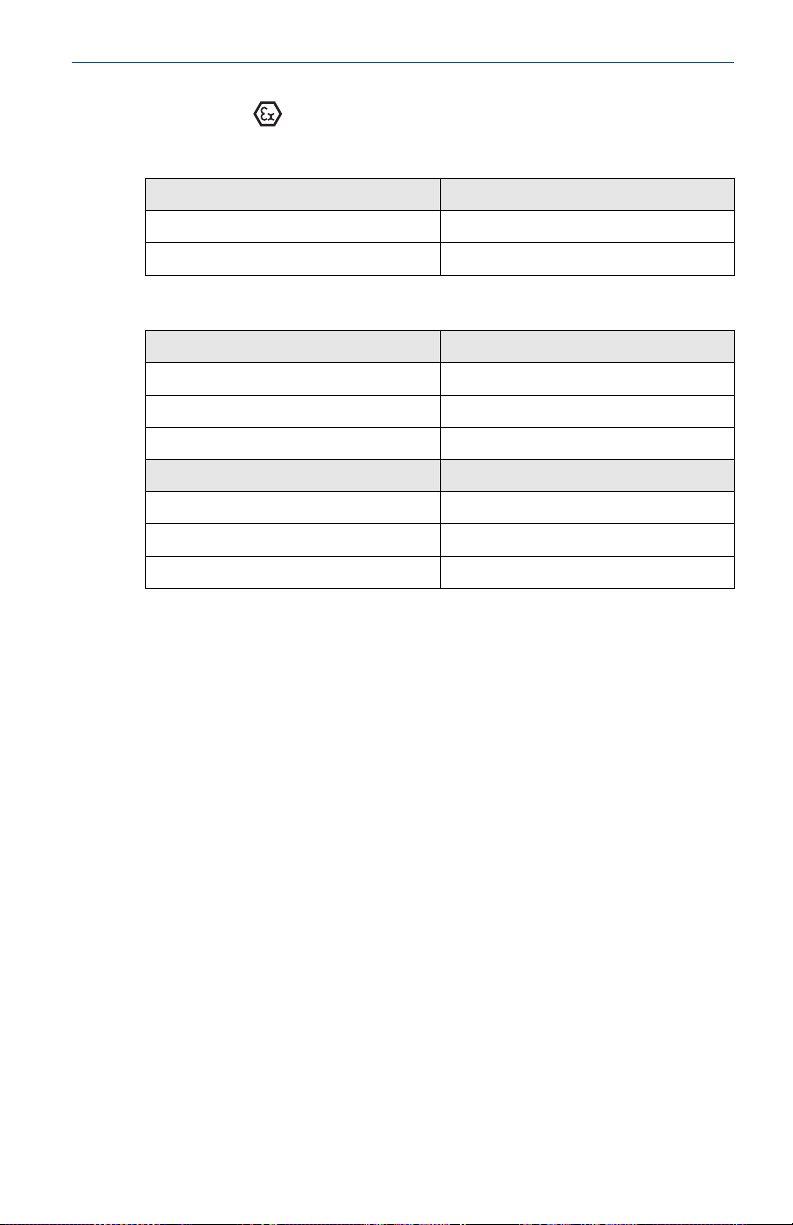
Table 5-8: Conduit plug thread sizes
Thread Identification mark
M20 x 1.5 M20
½–14 NPT ½ NPT
Table 5-9: Thread adapter thread sizes
Male thread Identification mark
M20 x 1.5–6g M20
½–14 NPT ½–14 NPT
¾–14 NPT ¾–14 NPT
Female thread Identification mark
M20 x 1.5–6H M20
½–14 NPT ½–14 NPT
G½ G½
Special Conditions for Safe Use (X):
1. When the thread adapter or blanking plug is used with an
enclosure in type of protection increased safety “e,” the entry
thread shall be suitably sealed in order to maintain the ingress
protection rating (IP) of the enclosure.
2. The blanking plug shall not be used with an adapter.
3. Blanking plug and threaded adapter shall be either NPT or
metric thread forms. G½ thread forms are only acceptable for
existing (legacy) equipment installations.
Quick Start Guide 39
Page 40
Quick Start Guide August2023
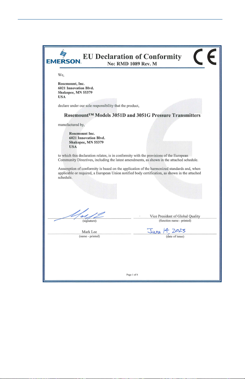
5.3 Declaration of Conformity
40 Rosemount 3051
Page 41
August2023 Quick Start Guide
Quick Start Guide 41
Page 42
Quick Start Guide August2023
42 Rosemount 3051
Page 43
August2023 Quick Start Guide
Quick Start Guide 43
Page 44
Quick Start Guide August2023
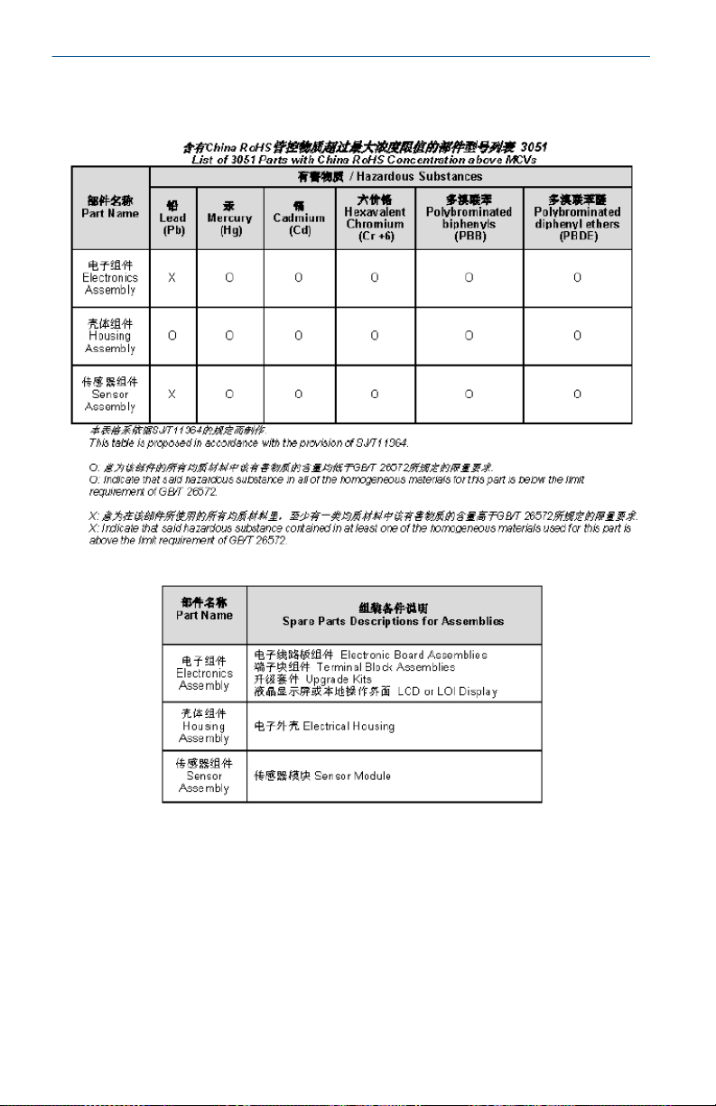
5.4 China RoHS
44 Rosemount 3051
Page 45

August2023 Quick Start Guide
Quick Start Guide 45
Page 46

Quick Start Guide August2023
46 Rosemount 3051
Page 47

August2023 Quick Start Guide
Quick Start Guide 47
Page 48

*00825-0100-5007*
Quick Start Guide
00825-0100-5007, Rev. DE
August2023
For more information:Emerson.com/global
©
2023 Emerson. All rights reserved.
Emerson Terms and Conditions of
Sale are available upon request. The
Emerson logo is a trademark and
service mark of Emerson Electric Co.
Rosemount is a mark of one of the
Emerson family of companies. All
other marks are the property of their
respective owners.
 Loading...