

Page 1
Instruction Manual
IB-106-300NH Rev. 4.3
May 2005
World Class 3000
Oxygen Analyzer
with IFT 3000 Intelligent
Field Transmitter
http://www.raihome.com
Page 2

ESSENTIAL INSTRUCTIONS
READ THIS PAGE BEFORE PROCEEDING!
Rosemount Analytical designs, manufactures and tests its products to meet many national and
international standards. Because these instruments are sophisticated technical products, you
MUST properly install, use, and maintain them to ensure they continue to operate within their
normal specifications. The following instructions MUST be adhered to and integrated into your
safety program when installing, using, and maintaining Rosemount Analytical products. Failure to
follow the proper instructions may cause any one of the following situations to occur: Loss of life;
personal injury; property damage; damage to this instrument; and warranty invalidation.
• Read all instructions prior to installing, operating, and servicing the product.
• If you do not understand any of the instructions, contact your Rosemount Analytical repre-
sentative for clarification.
• Follow all warnings, cautions, and instructions marked on and supplied with the product.
• Inform and educate your personnel in the proper installation, operation, and mainte-
nance of the product.
• Install your equipment as specified in the Installation Instructions of the appropriate In-
struction Manual and per applicable local and national codes. Connect all products to the
proper electrical and pressure sources.
• To ensure proper performance, use qualified personnel to install, operate, update, program,
and maintain the product.
• When replacement parts are required, ensure that qualified people use replacement parts
specified by Rosemount Analytical. Unauthorized parts and procedures can affect the product’s performance, place the safe operation of your process at risk, and VOID YOUR WAR-
RANTY. Look-alike substitutions may result in fire, electrical hazards, or improper op eration.
• Ensure that all equipment doors are closed and protective covers are in place, except
when maintenance is being performed by qualified persons, to prevent electrical shock
and personal injury.
If a Model 275/375 Universal HART® Communicator is used with this unit, the software within
the Model 275/375 communicator may require modification. If a software modification is required, please contact your local Fisher-Rosemount Service Group or National Response
Center at 1-800-654-7768.
The information contained in this document is subject to change without notice.
Emerson Process Management
Rosemount Analytical Inc.
Process Analytic Division
6565P Davis Industrial Parkway
Solon, OH 44139
T (440) 914 1261
F (440) 914 1271
E gas.csc@emersonprocess.com
http://www.raihome.com
Page 3

HIGHLIGHTS OF CHANGES
Effective May, 1999 Rev. 4.0
Page Summary
Page P-6 Added new Quick Start Guide.
Page 3-1 Added Section 3, Setup.
Page 4-1 Removed calibration information from Operation section, and created
Section 4, Calibration.
Page 6-2 Expanded explanations of IFT status codes.
Section 6 Added new troubleshooting procedures.
Effective November, 2001 Rev. 4.1
Page Summary
Highlights Updated Highlights of Changes Appendix A page.
Appendix A Replaced Appendix A, Rev. 3.6 with Rev. 3.7.
Effective November, 2001 Rev. 4.2
Page Summary
Highlights Updated Highlights of Changes Appendix A page.
Page 4-1 Added reference to new Calibration Record sheet.
Page 4-9 Added new Calibration Record sheet.
Appendix A Replaced Appendix A, Rev. 3.7 with Rev. 3.8.
Page 4

HIGHLIGHTS OF CHANGES (CONTINUED)
Effective May, 2005 Rev. 4.3
Page Summary
Highlights Updated Highlights of Changes Appendix A, B, D, E, J pages.
--- Changed “Rosemount” to “Rosemount Analytical”.
P-8 Revised Figure 2.
1-1 Revised Figure 1-1.
1-6 Revised Figure 1-3.
2-5, 2-6 Revised Figure 2-1, sheets 1 and 2.
2-9 Revised Figure 2-4.
2-13 Revised Figure 2-8.
2-14 Revised Figure 2-9.
2-15 Revised Figure 2-10.
2-18, 2-19 Revised Figure 2-14, sheets 1 and 2.
2-22 Revised Figure 2-18.
2-24 Revised Figure 2-20.
4-4 Revised Figure 4-1.
4-6 Revised Figure 4-3.
4-7 Revised Figure 4-4.
5-2 Revised Figure 5-1.
7-1 Changed RMR facility address.
Appendix A Replaced Appendix A, Rev. 3.8 with Rev. 3.9.
Appendix B Replaced Appendix B, Rev. 2.2 with Rev. 2.3.
Appendix D Replaced Appendix D, Rev. 2.4 with Rev. 2.5.
Appendix E Replaced Appendix E, Rev. 4.5 with Rev. 4.6.
Appendix J Replaced Appendix J, Rev. 1.1 with Rev. 1.2.
Back cover Changed Rosemount Analytical address.
Page 5

HIGHLIGHTS OF CHANGES
APPENDIX A
Effective May, 1996 Rev. 3
Page Summary
--- General. Updated appendix to reflect probe design changes.
Page A-13 Added “Extended temperature by-pass arrangements” to Figure A-13
(Sheet 3 of 3)
Effective June, 1996 Rev. 3.1
Page Summary
Page A-13 Updated part ordering information.
Effective August, 1996 Rev. 3.2
Page Summary
Page A-25 Updated cell replacement kit part numbers for the probe.
Effective October, 1996 Rev. 3.3
Page Summary
Page A-6 Added NOTE to Figure A-7.
Effective January, 1997 Rev. 3.4
Page Summary
Page A-1 Added warning to read new safety instructions.
Page A-12 Added protective covers and grounds warning.
Page A-16 Added protective covers and grounds warning.
Effective February, 1998 Rev. 3.5
Page Summary
Page A-18 Changed screw torque in paragraph A-11h.
Effective July, 1998 Rev. 3.6
Page Summary
--- Changed test gas to calibration gas and reference gas to reference
air throughout the appendix.
Page 6

HIGHLIGHTS OF CHANGES (CONTINUED)
Effective November, 2001 Rev. 3.7
Page Summary
A-8 Added new cup type diffusion assembly description, paragraph A-6.e.
and diffusion assembly illustrations, Figure A-13 and A-14.
A-26 Added new cup type diffusion assembly part numbers 4851B89G04
and 4851B90G04 to replacement parts list. Deleted stainless steel
diffuser assembly from replacement parts list.
Effective July, 2002 Rev. 3.8
Page Summary
A-13 Added troubleshooting symptoms 5 and 6 to Table A-2.
Effective May, 2005 Rev. 3.9
Page Summary
--- Changed “Rosemount” to “Rosemount Analytical”.
Page 7

HIGHLIGHTS OF CHANGES
APPENDIX B
Effective February, 1992 Rev. 2
Page Summary
Page B-1 Figure B- 1 . N e w HP S 3000 Optional Class 1, Division 1, Group B
(IP56) Explosion-Proof Enclosure added.
Page B-11 Figure a nd I n de x N o . co l u m n added to Table B-2. Replacement Parts
for Heater Power Supply.
Effective January, 1995 Rev. 2.1
Page Summary
Page B-3 Updated Figure B-3, Heater Power Supply Block Diagram for IB
consistency.
Effective January, 1997 Rev. 2.2
Page Summary
Page B-1 Added warning to read new safety instructions.
Page B-3 Corrected Table B-1 specifications list.
Page B-4 Added protective covers and grounds warning.
Page B-8 Added protective covers and grounds warning.
Page B-11 Added expanded fuse description.
Effective May, 2005 Rev. 2.3
Page Summary
--- Changed “Rosemount” to “Rosemount Analytical”.
Page 8

Page 9

HIGHLIGHTS OF CHANGES
Effective June, 1994 Rev. 2
Page Summary
APPENDIX D
Page D-1
Page D-2
Page D-3
Page D-4
Page D-7
Page D-8
Page D-10
Page D-11
Page Summary
Page D-1 Updated Figure D-1, MPS 300 0 to include hinge.
Page Summary
MPS outline drawing changed to show new MPS.
MPS interior view replaced with new MPS in Figure D-2.
"Optional" for check valve deleted in Figure D-3.
Drawing showing location of optional Z-Purge added as Figure D-4.
Power supply replacement procedures in paragraph D-7 changed to
reflect new design in the MPS. Solenoid valve replacement proce-
dures in paragraph D-8 changed to reflect new design in the MPS.
Old exploded view of MPS replaced with new MPS.
Paragraph D-11, Adding Probes to the new MPS, added.
Change part numbers for the power supply, solenoid valve, and test
gas flowmeter assembly. Add part numbers for reference gas flow-
meter assembly and all the parts in the probe adder kit.
Effective January, 1995 Rev. 2.1
Effective May, 1996 Rev. 2.2
Page D-11 Updated replacement parts list to reflect new part numbers.
Effective January, 1997 Rev. 2.3
Page Summary
Page D-1
Page D-2
Page D-5
Page D-7
Page D-11
Added warning to read new safety instructions.
Corrected Table D-1 Specifications listing, 1
Added protective covers and grounds warning.
Added protective covers and grounds warning, corrected item num-
ber errors in paragraph D-6.
Added expanded fuse descriptions.
st
entry.
Page 10

HIGHLIGHTS OF CHANGES (CONTINUED)
Effective July, 1998 Rev. 2.4
Page Summary
--- Changed test gas to calibration gas and reference gas to reference
air throughout the appendix.
Effective May, 2005 Rev. 2.5
Page Summary
--- Changed “Rosemount” to “Rosemount Analytical”.
D-3 Revised view of check valve in Figure D-3.
Page 11

HIGHLIGHTS OF CHANGES
APPENDIX E
Effective May, 1996 Rev. 4
Page Summary
--- General. Updated text and illustrations to reflect new version of IFT.
Page E-4 Updated IFT display status codes and placed in priority sequence.
Effective June, 1996 Rev. 4.1
Page Summary
Page E-2 Updated specification table.
Effective October, 1996 Rev. 4.2
Page Summary
Page E-4 Added new status displays for password protection features.
Effective January, 1997 Rev. 4.3
Page Summary
Front matter Added "Safety instructions for the wiring and installation of this
apparatus.”
Page E-1 Added warning to read new safety instructions.
Page E-2 Deleted NOTE.
Page E-4 Added protective covers and grounds warning.
Page E-8 Added protective covers and grounds warning.
Page E-15 Added expanded fuse description.
Effective July, 1998 Rev. 4.4
Page Summary
--- Changed test gas to calibration gas throughout the appendix.
Effective June, 1999 Rev. 4.5
Page Summary
Page E-1 Changed “real time clock” to “timer”.
--- Changed test gas to calibration gas and reference gas to reference
air throughout the appendix.
Page 12

HIGHLIGHTS OF CHANGES (CONTINUED)
Effective May, 2005 Rev. 4.6
Page Summary
--- Changed “Rosemount” to “Rosemount Analytical”. Changed views of
IFT 3000 enclosure. Named GUI/LED display standard (not optional).
E-2 Revised Electrical Noise specifications.
E-8 through E-16 Changed all service instructions to reflect new IFT 3000 assembly con-
figuration. Revised replacement parts list.
Page 13

HIGHLIGHTS OF CHANGES
APPENDIX J
Effective April, 1995 Rev. 1
Page Summary
Page J-13 Added statement of reference to the return authorization number.
Effective June, 1995 Rev. 1.1
Page Summary
--- Figure J-4. Updated figure to include “Status group” and “K3 eff” in
calculations.
Effective May, 2005 Rev. 1.2
Page Summary
J-1 Revised Figure J-1 to show Model 375 Communicator.
J-3, J5 Revised Figure J-2 and J-3 to show location of new microprocessor
board switches.
J-13 Revised RMR facility address.
Page 14

Page 15

World Class 3000
PREFACE........................................................................................................................P-1
Definitions........................................................................................................................P-1
Safety Instructions..........................................................................................................P-2
Glossary of Terms.........................................................................................................P-3
Quick Start Guide..........................................................................................................P-6
1-0 DESCRIPTION AND SPECIFICATIONS...................................................................... 1-1
1-1 Component Checklist of Typical System (Package Contents).................................. 1-1
1-2 System Overview............................................................................................................ 1-2
2-0 INSTALLATION .............................................................................................................. 2-1
2-1 Oxygen Analyzer (Probe) Installation........................................................................... 2-1
2-2 Intelligent Field Transmitter (IFT) Installation.............................................................. 2-9
2-3 Heater Power Supply Installation ............................................................................... 2-13
2-4 Multiprobe Calibration Gas Sequencer Installation.................................................. 2-21
3-0 SETUP............................................................................................................................. 3-1
3-1 Overview.......................................................................................................................... 3-1
3-2 Configuring the Analog Output..................................................................................... 3-1
3-3 Setting Calibration Parameters ...................................................................................... 3-1
3-4 Setting the O
3-5 Configuring Efficiency Calculations............................................................................... 3-2
3-6 Configuring the Relay Outputs ..................................................................................... 3-2
Instruction Manual
IB-106-300NH Rev. 4.3
TABLE OF CONTENTS
Alarm Setpoints.................................................................................... 3-2
2
May 2005
4-0 CALIBRATION................................................................................................................ 4-1
4-1 Analog Output Calibration ............................................................................................. 4-1
4-2 System Calibration ......................................................................................................... 4-1
5-0 GENERAL USER INTERFACE (GUI) OPERATION.................................................. 5-1
5-1 Overview.......................................................................................................................... 5-1
5-2 Deluxe Version IFT Displays and Controls................................................................. 5-2
5-3 Help Key......................................................................................................................... 5-3
5-4 Status Line...................................................................................................................... 5-3
5-5 Quick Reference Chart.................................................................................................. 5-3
5-6 Main Menu...................................................................................................................... 5-3
5-7 Probe Data Sub-Menu................................................................................................... 5-3
5-8 Calibrate O
5-9 Setup Sub-Menu............................................................................................................. 5-4
6-0 TROUBLESHOOTING.................................................................................................... 6-1
6-1 Overview.......................................................................................................................... 6-1
6-2 Special Troubleshooting Notes ..................................................................................... 6-1
6-3 System Troubleshooting................................................................................................. 6-1
6-4 Heater Problem ..............................................................................................................6-3
6-5 Cell Problem................................................................................................................... 6-5
6-6 IFT Problem.................................................................................................................... 6-7
6-7 MPS Problem .................................................................................................................6-8
6-8 Performance Problem (Process Response is Suspect)............................................. 6-9
Sub-Menu ................................................................................................. 5-4
2
Rosemount Analytical Inc. A Division of Emerson Process Management i
Page 16

Instruction Manual
IB-106-300NH Rev. 4.3
May 2005
7-0 RETURN OF MATERIAL.............................................................................................. 7-1
8-0 APPENDICES ................................................................................................................. 8-1
Appendix A ......................................................................................................................A-1
Appendix B ......................................................................................................................B-1
Appendix D......................................................................................................................D-1
Appendix E ......................................................................................................................E-1
Appendix J........................................................................................................................J-1
9-0 INDEX.............................................................................................................................. 9-1
Figure 1. Complete World Class 3000 System.....................................................................P-5
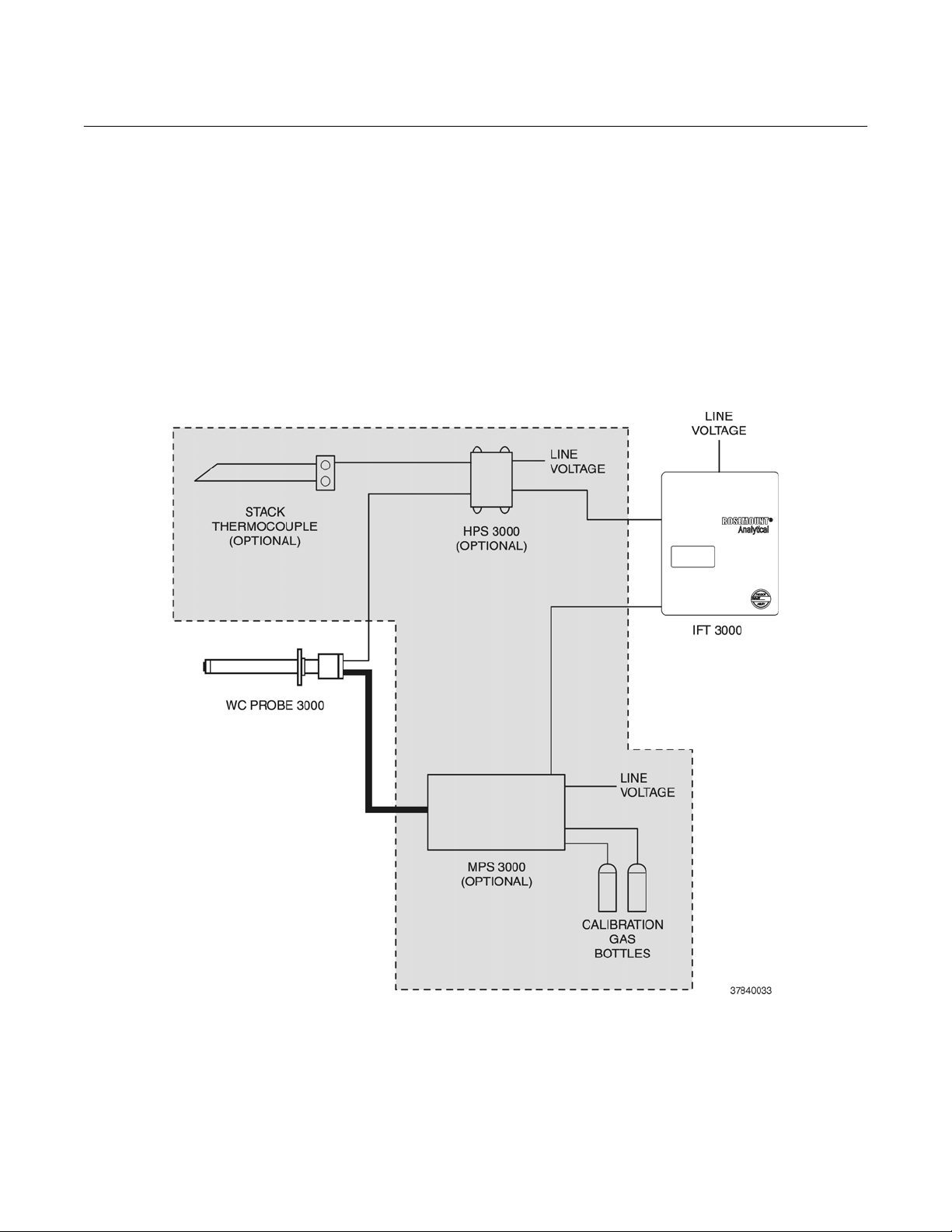
Figure 2. Wiring Layout for World Class 3000 System without HPS or MPS.......................P-8
Figure 1-1. Typical System Package ....................................................................................... 1-1
Figure 1-2. Typical System Installation.................................................................................... 1-5
Figure 1-3. World Class 3000 Typical Application with Intelligent Field Transmitters ............. 1-6
Figure 2-1. Probe Installation................................................................................................... 2-2
Figure 2-2. Orienting the Optional Vee Deflector..................................................................... 2-7
Figure 2-3. Air Set, Plant Air Connection................................................................................. 2-8
Figure 2-4. Outline of Intelligent Field Transmitter................................................................... 2-9
Figure 2-5. Power Supply Board Jumper Configuration ........................................................ 2-10
Figure 2-6. IFT Power Supply Board Jumpers....................................................................... 2-11
Figure 2-7. Wiring Layout for IFT Systems without HPS ....................................................... 2-12
Figure 2-8. Microprocessor Board Jumper Configuration.....................................................2-13
Figure 2-9. IFT Microprocessor Board................................................................................... 2-14
Figure 2-10. Interconnect Board Jumper Configuration........................................................... 2-15
Figure 2-11. IFT Interconnect Board Output Connections....................................................... 2-15
Figure 2-12. Outline of Heater Power Supply .......................................................................... 2-16
Figure 2-13. Wiring Layout for Complete IFT 3000 System with HPS..................................... 2-17
Figure 2-14. Heater Power Supply Wiring Connections .......................................................... 2-19
Figure 2-15. Jumper Selection Label....................................................................................... 2-20
Figure 2-16. Jumpers on HPS Mother Board........................................................................... 2-20
Figure 2-17. MPS Module ........................................................................................................2-21
Figure 2-18. MPS Gas Connections ........................................................................................ 2-22
Figure 2-19. MPS Probe Wiring............................................................................................... 2-23
Figure 4-1. Typical Calibration Setup....................................................................................... 4-4
Figure 4-2. Portable Rosemount Analytical Oxygen Calibration Gas Kit................................. 4-5
Figure 4-3. Typical Portable Calibration Setup ........................................................................ 4-6
Figure 4-4. Typical Automatic Calibration System................................................................... 4-7
Figure 5-1. Deluxe Version IFT Displays and Controls............................................................ 5-2
Figure 5-2. Quick Reference Chart.......................................................................................... 5-5
World Class 3000
LIST OF ILLUSTRATIONS
ii Rosemount Analytical Inc. A Division of Emerson Process Management
Page 17

World Class 3000
Table 4-1. Automatic Calibration Parameters......................................................................... 4-8
Table 5-1. Sample HELP Messages....................................................................................... 5-3
Table 5-2. MAIN menu............................................................................................................ 5-3
Table 5-3. PROBE DATA Sub-Menu......................................................................................5-4
Table 5-4. CALIBRATE O
Table 5-5. SETUP Sub-Menu............................................................................................... 5-12
Table 5-6. Efficiency Constants ............................................................................................ 5-14
Table 6-1. IFT Status Codes................................................................................................... 6-2
Table 6-2. Heater Troubleshooting......................................................................................... 6-3
Table 6-3. Cell Troubleshooting.............................................................................................. 6-5
Table 6-4. IFT Troubleshooting............................................................................................... 6-7
Table 6-5. MPS Troubleshooting............................................................................................ 6-8
Table 6-6. Performance Problem Troubleshooting................................................................. 6-9
Instruction Manual
IB-106-300NH Rev. 4.3
LIST OF TABLES
Sub-Menu..................................................................................5-10
2
May 2005
Rosemount Analytical Inc. A Division of Emerson Process Management iii
Page 18

Instruction Manual
IB-106-300NH Rev. 4.3
May 2005
World Class 3000
iv Rosemount Analytical Inc. A Division of Emerson Process Management
Page 19
World Class 3000
The purpose of this manual is to provide a comprehensive understanding of the World
Class 3000 Oxygen Analyzer components, functions, installation, and maintenance.
This manual is designed to provide information about the World Class 3000 Oxygen Analyzer. We recommend that you familiarize yourself with the Overview and Installation sections before installing your emissions monitor.
The overview presents the basic principles of the oxygen analyzer along with its performance characteristics and components. The remaining sections contain detailed procedures and information necessary to install and service the oxygen analy zer.
NOTE
!
Only one probe can be calibrated at a time.
Probe calibrations must be scheduled
appropriately in multiple probe applications.
PREFACE
DEFINITIONS
Instruction Manual
IB-106-300NH Rev. 4.3
May 2005
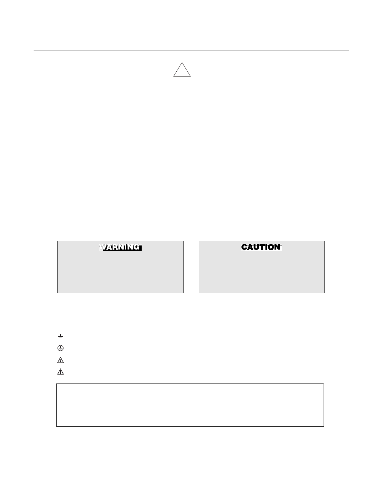
The following definitions apply to WARNINGS, CAUTIONS, and NOTES found throughout this
publication.
Highlights an operation or maintenance
procedure, practice, condition, statement, etc. If not strictly observed, could
result in injury, death, or long-term
health hazards of personnel.
NOTE
Highlights an essential operating procedure,
condition, or statement.
: EARTH (GROUND) TERMINAL
: PROTECTIVE CONDUCTOR TERMINAL
: RISK OF ELECTRICAL SHOCK
: WARNING: REFER TO INSTRUCTION BULLETIN
Highlights an operation or maintenance
procedure, practice, condition, statement, etc. If not strictly observed, could
result in damage to or destruction of
equipment, or loss of effectiveness.
NOTE TO USERS
The number in the lower right corner of each illustration in this publication is a manual illustration number. It is not a part number, and is not related to the illustration in any technical
manner.
Rosemount Analytical Inc. A Division of Emerson Process Management P-1
Page 20
Instruction Manual
IB-106-300NH Rev. 4.3
May 2005
FOR THE WIRING AND INSTALLATION
The following safety instructions apply specifically to all EU member states. They should
be strictly adhered to in order to assure compliance with the Low Voltage Directive. NonEU states should also comply with the following unless superseded by local or National
Standards.
1. Adequate earth connections should be made to all earthing points, internal and external,
where provided.
2. After installation or troubleshooting, all safety covers and safety grounds must be replaced.
The integrity of all earth terminals must be maintained at all times.
3. Mains supply cords should comply with the requirements of IEC227 or IEC245.
World Class 3000
IMPORTANT
SAFETY INSTRUCTIONS
OF THIS APPARATUS
4. All wiring shall be suitable for use in an ambient temperature of greater than 75°C.
5. All cable glands used should be of such internal dimensions as to provide adequate cable
anchorage.
6. To ensure safe operation of this equipment, connection to the mains supply should only be
made through a circuit breaker which will disconnect all circuits carrying conductors during a
fault situation. The circuit breaker may also include a mechanically operated isolating switch.
If not, then another means of disconnecting the equipment from the supply must be provided
and clearly marked as such. Circuit breakers or switches must comply with a recogn ized
standard such as IEC947. All wiring must conform with any local standards.
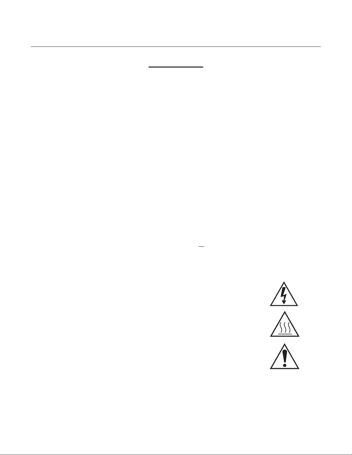
7. Where equipment or covers are marked with the symbol to the right, hazardous voltages are likely to be present beneath. These covers should only be
removed when power is removed from the equipment — and then only by
trained service personnel.
8. Where equipment or covers are marked with the symbol to the right, there is a
danger from hot surfaces beneath. These covers should only be removed by
trained service personnel when power is removed from the equipment. Certain surfaces may remain hot to the touch.
9. Where equipment or covers are marked with the symbol to the right, refer to
the Operator Manual for instructions.
10. All graphical symbols used in this product are from one or more of the following standards: EN61010-1, IEC417, and ISO3864.
P-2 Rosemount Analytical Inc. A Division of Emerson Process Management
Page 21

World Class 3000
Abrasive Shield
An optional component that shields the probe from high velocity particulate entrained in the flue
gas stream.
Automatic Calibration
An automatic calibration can only be performed if the system is equipped with an MPS 3000 Multiprobe Calibration Gas Sequencer. Once a calibration is initiated by the operator or by the IFT on
a scheduled interval, all calibration actions are performed by the IFT. The MPS switched calibration gases under direction from the IFT.
Calibration
The process of measuring gases of a known concentration, and comparing that known concentration to the actual values sensed by the instrument. After reading the calibration gases, the IFT
automatically adjusts the slope and constant values to ensure that the system is correctly reading
the process gas O
Cold Junction Compensation
A method for compensating for the small voltage developed at the junction of the thermocouple
leads in the probe junction box.
values.
2
Instruction Manual
IB-106-300NH Rev. 4.3
May 2005
GLOSSARY OF TERMS
Dead Band
The range through which a signal can be varied without initiating a response. In the IFT 3000,
dead band is used to prevent an oxygen signal near an alarm setpoint from cycling the alarm on
and off.
GUI
General User Interface. The GUI is the operator interface for the IFT 3000.
HART
A communications protocol using frequency shift keying (FSK) to transmit data on an analog output line without affecting the analog output signal.
HPS
Heater Power Supply. An HPS should be used to provide power for the probe heater if the probe
is more than 150 ft (45 m) from the IFT.
IFT
Intelligent Field Transmitter.
In Situ
A method of analyzing process gases without removing them from the process stream.
MPS
Multiprobe Calibration Gas Sequencer. The MPS can provide automatic calibration gas sequencing for up to four probes.
Rosemount Analytical Inc. A Division of Emerson Process Management P-3
Page 22

Instruction Manual
IB-106-300NH Rev. 4.3
May 2005
Reference Air
Provides a known oxygen concentration to the reference side of the oxygen sensing cell.
Semiautomatic Calibration
Semiautomatic calibration is performed when the system does not include an MPS 3000 Multiprobe Calibration Gas Sequencer. The IFT 3000 provides prompts to direct the user to switch
calibration gases when performing the calibration.
Thermocouple
An electrical device made of two dissimilar metals. A thermocouple develops a millivolt signal
proportional to its temperature.
Vee Deflector
Protects the optional ceramic diffusor from the process gases. The vee deflector must be positioned so it points toward the direction of the process gas flow. See Figure 2-2 for an illustration of
the vee deflector.
World Class 3000
P-4 Rosemount Analytical Inc. A Division of Emerson Process Management
Page 23
World Class 3000
BEFORE INSTALLING AND WIRING A ROSEMOUNT ANALYTICAL
IFT 3000 INTELLIGENT FIELD TRANSMITTER
1. What is the line voltage being supplied to the IFT 3000?
Write the line voltage here __________
2. Use the following drawing, Figure 1, to identify which parts of the World Class 3000 system
are included in your system. Components in the shaded area are optional components.
Instruction Manual
IB-106-300NH Rev. 4.3
May 2005
WHAT YOU NEED TO KNOW
WITH WORLD CLASS 3000 PROBE
Figure 1. Complete World Class 3000 System
Rosemount Analytical Inc. A Division of Emerson Process Management P-5
Page 24

Instruction Manual
IB-106-300NH Rev. 4.3
May 2005
Use this Quick Start Guide if ...
1. You are using a World Class 3000 probe.
2. You are NOT using any optional components. Optional components are shown in the
shaded area in Figure 1.
3. You are familiar with the installation requirements for the IFT 3000 Intelligent Field Transmitter and World Class 3000 probe.
4. You are familiar with the procedures for changing the jumpers located in the IFT 3000, as
described in Section 2, Installation.
If you cannot use the Quick Start Guide, turn to Section 2, Installation, in this Instruction
Manual.
World Class 3000
QUICK START GUIDE
P-6 Rosemount Analytical Inc. A Division of Emerson Process Management
Page 25

World Class 3000
QUICK START GUIDE FOR IFT 3000 SYSTEMS
Before using the Quick Start Guide, please read “WHAT YOU NEED TO KNOW BEFORE
INSTALLING AND WIRING A ROSEMOUNT ANALYTICAL IFT 3000 INTELLIGENT
FIELD TRANSMITTER WITH WORLD CLASS 3000 PROBE” on the preceding page.
1. Install the probe in an appropriate location on the stack or duct. Refer to Section 2, paragraph 2-1a for information on selecting a location for the probe.
2. Connect calibration gas and reference air to the probe.
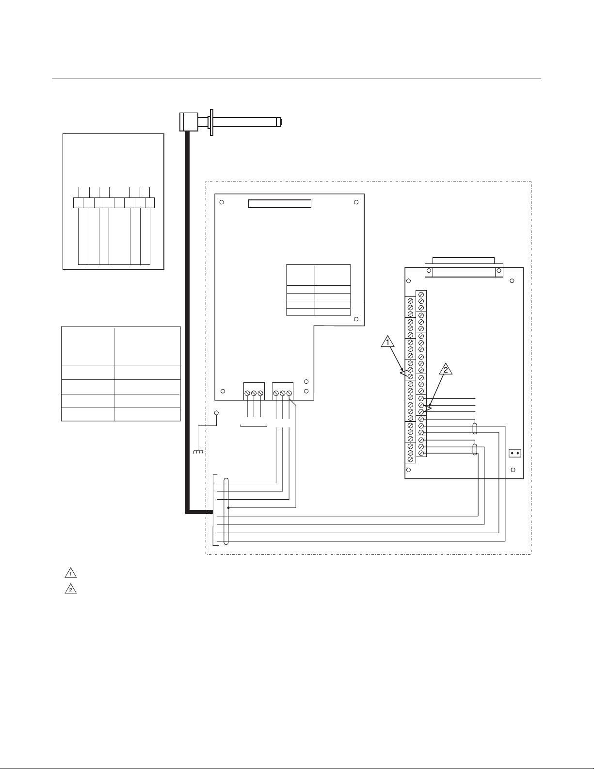
3. Verify the jumper selection on the IFT 3000 power supply board, microprocessor board, and
interconnect board, as shown in Figure 2.
4. Install the IFT 3000 in the desired location. Refer to Section 2, paragraph 2-2a for information on selecting a location for the IFT 3000.
5. Wire the probe to the IFT as shown in Figure 2.
Instruction Manual
IB-106-300NH Rev. 4.3
May 2005
6. Connect line voltage to the IFT as shown in Figure 2.
7. Apply power to the IFT 3000. Allow sufficient time for the probe to reach normal operating
temperature. The time required will vary based on process temperature and other variables.
8. Perform a manual (semiautomatic) calibration. Press the CAL key on the GUI. Select the
PERFORM CALIBRATION sub-menu. “Press ENTER to start Manual Calibration” will
appear on the LCD display. Press ENTER to start the calibration process. Follow the instructions on the LCD display. Refer to Section 4, Calibration, for more information on performing a calibration.
Rosemount Analytical Inc. A Division of Emerson Process Management P-7
Page 26
Instruction Manual
IB-106-300NH Rev. 4.3
May 2005
PROBE JUNCTION
BOX WIRING
HEATER
YE CHROMEL
OR CELL +VE
GN CELL -VE
RD ALUMEL
GN
BK
World Class 3000
WORLD CLASS
PROBE
}
BK
INTELLIGENT FIELD TRANSMITTER IFT 3000
123456 78
BL
YE
RD
OR
PROBE TC +
PROBE MV +
PROBE MV -
GN
E
PROBE TC -
LINE
VOLTAGE
SECTION
100 V.A.C.
120 V.A.C.
220 V.A.C.
240 V.A.C.
LINE VOLTAGE
JUMPERS ON IFT
POWER SUPPLY
JUMPER
(INSTALL)
JM3, JM7, JM2
JM8, JM7, JM1
JM6, JM5, JM2
JM6, JM5, JM1
BOARD
WH
R
BK
H
J1
3D39122G REV
POWER SUPPLY BOARD
LINE
VOLTAGE
SECTION
100 V.A.C.
JM3, JM7, JM2
120 V.A.C.
JM8, JM7, JM1
220 V.A.C.
JM6, JM5, JM2
JM6, JM5, JM1
240 V.A.C.
JUMPER
(INSTALL)
J2
3D39120G REV
INTERCONNECT BOARD
J3
J1
J4
J5
J6
J5 J6
J7
SHIELD
STACK TC -
GND
STUD
L
LINE
VOLTAGE
BK
WH
GN
PU
OR
BL
YE
RD
H
EN
ER
STACK TC +
J8
SHIELD
PROBE TC -
RD
YE
PROBE TC +
J9
SHIELD
BL
PROBE MV
PROBE
OR
-
MV+
JM1
NOTES:
INSTALL JUMPER ACROSS TERMINALS 13 AND 14.
INSTALL JUMPER ACROSS TERMINALS 7 AND 8.
37840003
Figure 2. Wiring Layout for World Class 3000 System without HPS or MPS
P-8 Rosemount Analytical Inc. A Division of Emerson Process Management
Page 27

World Class 3000
IFT 3000 INTELLIGENT FIELD TRANSMITTER
Performing a Manual (Semiautomatic) Calibration
1. Connect the high calibration gas to the probe fitting.
2. Press the CAL key.
3. Select the PERFORM CALIBRATION sub-menu.
4. Press the ENTER key.
5. Turn on the high calibration gas.
Instruction Manual
IB-106-300NH Rev. 4.3
May 2005
QUICK REFERENCE GUIDE
6. When the O
7. Turn off the high calibration gas and turn on the low calibration gas.
8. Press Enter.
9. When the O
10. The LCD display will show “Resistance Check”. When the display changes to “Turn off low
calibration gas”, turn off the low calibration gas and press ENTER.
11. When the oxygen reading has stabilized at the process value, press ENTER.
Setting up the Analog Output
1. Press the SETUP key.
2. Select the Analog Output sub-menu.
3. Set the SOURCE to O
Dual Range O
4. Set the AOUT TYPE to the desired setting. Note that the setting must agree with the position
of the analog output selector switch. If you will communicate with the IFT using HART communications, the AOUT TYPE must be set to HART 4-20mA.
5. Select Range Setup and press ENTER.
6. Set the Xfer Fnct to Lin or Log, as desired.
7. Select Range Values and press ENTER.
reading is stable, press ENTER.
2
reading is stable, press ENTER.
2
. For information on configuring the analog output for Efficiency or
2
, refer to Section V, Operation.
2
8. Set the High End to the oxygen concentration to be represented by the high analog output
value, i.e., 20mA or 10V.
9. Set the Low End to the oxygen concentration to be represented by the low analog output
value, i.e., 0 or 4mA or 0V.
10. Press the ESC key until you are back at the Main menu.
Rosemount Analytical Inc. A Division of Emerson Process Management P-9
Page 28

Instruction Manual
IB-106-300NH Rev. 4.3
May 2005
HART COMMUNICATOR FAST KEY SEQUENCES
Toggle Analog Output Tracking View O2 Value
World Class 3000
Perform Calibration Analog Output Upper Range Value
2313 324
Trim Analog Output Analog Output Lower Range Value
24 325
2312 111
View Analog Output
121
Technical Support Hotline:
For assistance with technical problems, please call the Customer Support Center (CSC). The
CSC is staffed 24 hours a day, 7 days a week.
Phone: 1-800-433-6076
In addition to the CSC, you may also contact Field Watch. Field Watch coordinates Rosemount
Analytical’s field service throughout the US and abroad.
Phone: 1-800-654-RSMT (1-800-654-7768)
Rosemount Analytical may also be reached via the Internet through e-mail and the World Wide
Web:
E-mail: GAS.CSC@emersonprocess.com
World Wide Web: www.raihome.com
P-10 Rosemount Analytical Inc. A Division of Emerson Process Management
Page 29
World Class 3000
DESCRIPTION AND SPECIFICATIONS
Instruction Manual
IB-106-300NH Rev. 4.3
May 2005
SECTION 1
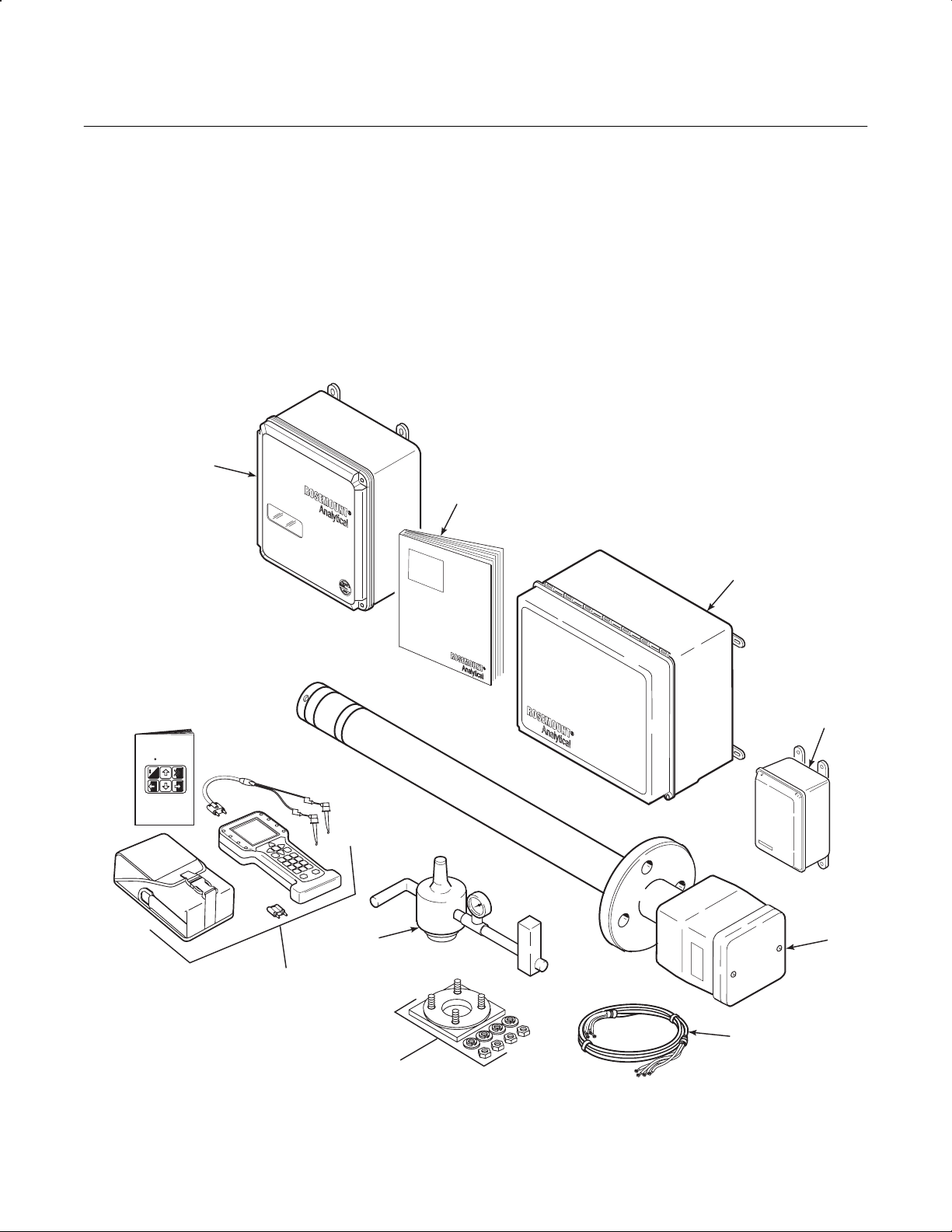
1-1 COMPONENT CHECKLIST OF TYPICAL
SYSTEM (PACKAGE CONTENTS)
A typical Rosemount Analytical World Class
3000 Oxygen Analyzer with IFT 3000 Intelligent
1
Field Transmitter should contain the items
shown in Figure 1-1. Record the part number,
serial number, and order number for each component of your system in the table located on
the first page of this manual.
1. Intelligent Field Transmitter
2. Instruction Manual
3. Multiprobe Calibration Gas Sequencer (Optional)
4. Heater Power Supply (Optional)
5. Oxygen Analyzer (Probe)
6. System Cable
7. Adapter Plate with mounting
2
hardware and gasket
8. Reference Air Set (If MPS not supplied)
9. HART
®
Communicator Package (Optional)
3
4
5
37840019
HART
MAN4275A00
October1994
Communicator
o
FISHER-ROSEMOUNT
English
TM
8
9
6
7
Figure 1-1. Typical System Package
Rosemount Analytical Inc. A Division of Emerson Process Management Description and Specifications 1-1
Page 30

Instruction Manual
IB-106-300NH Rev. 4.3
May 2005
World Class 3000
1-2 SYSTEM OVERVIEW
a. Scope
This Instruction Manual has been designed
to supply details needed to install, startup,
operate, and maintain the Rosemount Analytical World Class 3000 Oxygen Analyzer
with IFT 3000 Intelligent Field Transmitter.
The Intelligent Field Transmitter (IFT) can
be interfaced with one World Class 3000
probe. The IFT provides all necessary intelligence for controlling the probe and optional MPS 3000 Multiprobe Calibration Gas
Sequencer. Appendices at the back of this
manual detail each component and option
from the standpoint of troubleshooting, repair, and spare parts.
Operator/Technician interface to the IFT
can be provided from the displays and keypads on the front panel, and remotely
through HART
utilizing the 4-20 mA out-put signal from the
IFT interconnect board. HART Communicator IFT applications are detailed in
Appendix J.
b. System Description
The Rosemount Analytical Oxygen Analyzer
(Probe) is designed to measure the net
concentration of oxygen in an industrial process; i.e., the oxygen remaining after all fuels have been oxidized. The probe is
permanently positioned within an exhaust
duct or stack and performs its task without
the use of a sampling system.
The equipment measures oxygen percentage by reading the voltage developed
across a heated electrochemical cell, which
consists of a small yttria-stabilized, zirconia
disc. Both sides of the disc are coated with
porous metal electrodes. When operated at
the proper temperature, the millivolt output
voltage of the cell is given by the following
Nernst equation:
®
communications protocol,
Where:
1. P2 is the partial pressure of the oxygen
in the measured gas on one side of the
cell,
2. P1 is the partial pressure of the oxygen
in the reference air on the other side,
3. T is the absolute temperature,
4. C is the cell constant,
5. K is an arithmetic constant.
NOTE
For best results, use clean, dry, instrument air (20.95% oxygen) as a reference air.
When the cell is at operating temperature
and there are unequal oxygen concentrations across the cell, oxygen ions will travel
from the high partial pressure of oxygen
side to the low partial pressure side of the
cell. The resulting logarithmic output voltage
is approximately 50 mV per decade. Because the magnitude of the output is proportional to the logarithm of the inverse of
the sample of the oxygen partial pressure,
the output signal increases as the oxygen
concentration of the sample gas decreases.
This characteristic enables the oxygen
analyzer to provide exceptional sensitivity at
low oxygen concentrations.
Oxygen analyzer equipment measures net
oxygen concentration in the presence of all
the products of combustion, including water
vapor. Therefore, it may be considered an
analysis on a "wet" basis. In comparison
with older methods, such as the Orsat apparatus, which provides an analysis on a
"dry" gas basis, the "wet" analysis will, in
general, indicate a lower percentage of
oxygen. The difference will be proportional
to the water content of the sampled gas
stream.
EMF = KT log10(P1/P2) + C
1-2 Description and Specifications Rosemount Analytical Inc. A Division of Emerson Process Management
Page 31

World Class 3000
Instruction Manual
IB-106-300NH Rev. 4.3
May 2005
c. System Configuration
The equipment covered in this manual consists of three major components: the oxygen analyzer (probe), the intelligent field
transmitter (IFT), and an optional heater
power supply (HPS). The HPS is required
where the cable run between the probe and
the electronics is greater than 150 ft (45 m).
There is also an optional multiprobe calibration gas sequencer (MPS) to facilitate
automatic calibration of the probe.
Probes are available in five length options,
giving the user the flexibility to use an in situ
penetration appropriate to the size of the
stack or duct. The options on length are 18
in. (457 mm), 3 ft (0.91 m), 6 ft (1.83 m), 9 ft
(2.7 m), or 12 ft (3.66 m).
The IFT contains electronics that control
probe temperature (in conjunction with the
optional HPS), supply power, and provide
isolated outputs that are proportional to the
measured oxygen concentration. The oxygen sensing cell is maintained at a constant
temperature by modulating the duty cycle of
the probe heater. The IFT accepts millivolt
signals generated by the sensing cell and
produces outputs to be used by remotely
connected devices. The IFT output is isolated and selectable to provide linearized
voltage or current.
The heater power supply (HPS) can provide
an interface between the IFT and the probe.
The HPS contains a transformer for supplying proper voltage to the probe heater.
The enclosure has been designed to meet
NEMA 4X (IP56) specifications for water
tightness; an optional enclosure to meet
Class 1, Division 1, Group B (IP56) explosion proof is also available.
Systems with multiprobe and multiple IFT
applications may employ an optional MPS
3000 Multiprobe Calibration Gas Se-
quencer. The MPS 3000 provides automatic
calibration gas sequencing for up to four
probes and IFTs to accommodate automatic
calibration.
d. System Features
1. Unique and patented electronic cell
protection action that automatically
protects sensor cell when the analyzer
detects reducing atmospheres.
2. Output voltage and sensitivity increase
as the oxygen concentration
decreases.
3. User friendly, menu driven operator
interface with context-sensitive on-line
help.
4. Field replaceable cell.
5. Analyzer constructed of rugged 316
LSS for all wetted parts.
6. The intelligent field transmitter (IFT)
can be located up to 150 ft (45 m) from
the probe when used without optional
heater power supply (HPS). When the
system includes the optional HPS, the
HPS can be located up to 150 ft (45 m)
from the probe and the IFT may be located up to 1200 ft (364 m) from the
HPS.
7. All electronic modules are adaptable to
100, 120, 220, and 240 line voltages.
8. Five languages may be selected for
use with the Intelligent Field
Transmitter:
English Italian
French Spanish
German
Rosemount Analytical Inc. A Division of Emerson Process Management Description and Specifications 1-3
Page 32

Instruction Manual
IB-106-300NH Rev. 4.3
May 2005
World Class 3000
9. An operator can set up, calibrate, or
troubleshoot the IFT in one of two
ways:
(a) Optional General User Interface
(GUI). The GUI is housed within
the IFT electronics enclosure and
makes use of an LCD and keypad.
(b) Optional HART Interface. The IFT's
4-20 mA output line transmits an
analog signal proportional to oxygen level. The line also carries all
information normally accessed by
use of the General User Interface
LCD and keypad. This information
can be accessed through the
following:
1 Rosemount Analytical Model
275/375 Handheld Communicator - The handheld communicator requires Device
Descriptor (DD) software specific to the World Class 3000
product. The DD software will
be supplied with many model
275/375 units, but can also be
programmed into existing
units at most FisherRosemount service offices.
2 Personal Computer (PC) -
The use of a personal computer requires Cornerstone
software with Module Library
(ModLib) specific to the World
Class 3000 product.
3 Selected Distributed Control
Systems - The use of distributed control systems requires
input/output (I/O) hardware
and software which permit
HART communications.
e. Handling the Oxygen Analyzer.
It is important that printed circuit
boards and integrated circuits are
handled only when adequate antistatic
precautions have been taken to prevent possible equipment damage.
The oxygen analyzer is designed for
industrial application. Treat each
component of the system with care to
avoid physical damage. The probe
contains components made from ceramics, which are susceptible to
shock when mishandled.
NOTE
Retain packaging in which the oxygen
analyzer arrived from the factory in
case any components are to be
shipped to another site. This packaging has been designed to protect the
product.
f. System Considerations
Prior to installation of your Rosemount
Analytical World Class 3000 Oxygen Analyzer with Intelligent Field Transmitter make
sure that you have all of the components
necessary to make the system installation.
Ensure that all the components are properly
integrated to make the system functional.
Once you have verified that you have all the
components, select mounting locations and
determine how each component will be
placed in terms of available power supply,
ambient temperatures, environmental considerations, convenience, and serviceability.
A typical system installation is illustrated in
Figure 1-2. Figure 1-3 shows a typical system wiring. For details on installing the individual components of the system, refer to
Section 2, Installation.
1-4 Description and Specifications Rosemount Analytical Inc. A Division of Emerson Process Management
Page 33

World Class 3000
Instruction Manual
IB-106-300NH Rev. 4.3
May 2005
CALIBRATI ON
INSTRUMENT
AIR SUPPLY
(REF. AIR)
GAS
PRESSURE
REGULATOR
GASES
STACK
FLOWMETER
STANDARD
DUCT
OXYGEN
ANALYZER
(PROBE)
INTELLIGENT
FIELD TRANSMITTER
MULTI PROBE
CALIBRATI ON GAS
SEQUENCER
LINE
VOLTAGE
}
ADAPTER
PLATE
ADAPTER
PLATE
CALIBRATI ON
GAS
GASES
STACK
OPTIONS
DUCT
OXYGEN
ANALYZER
(PROBE)
SUPPLY
INST. AIR
CAL GAS 1
CAL GAS 2
REFERENCEAIR
Figure 1-2. Typical System Installation
HEATER
POWER
SUPPLY
INTELLIGENT FIELD
TRANSMITTER
}
LINE
VOLTAGE
27270001
Rosemount Analytical Inc. A Division of Emerson Process Management Description and Specifications 1-5
Page 34
Instruction Manual
IB-106-300NH Rev. 4.3
May 2005
World Class 3000
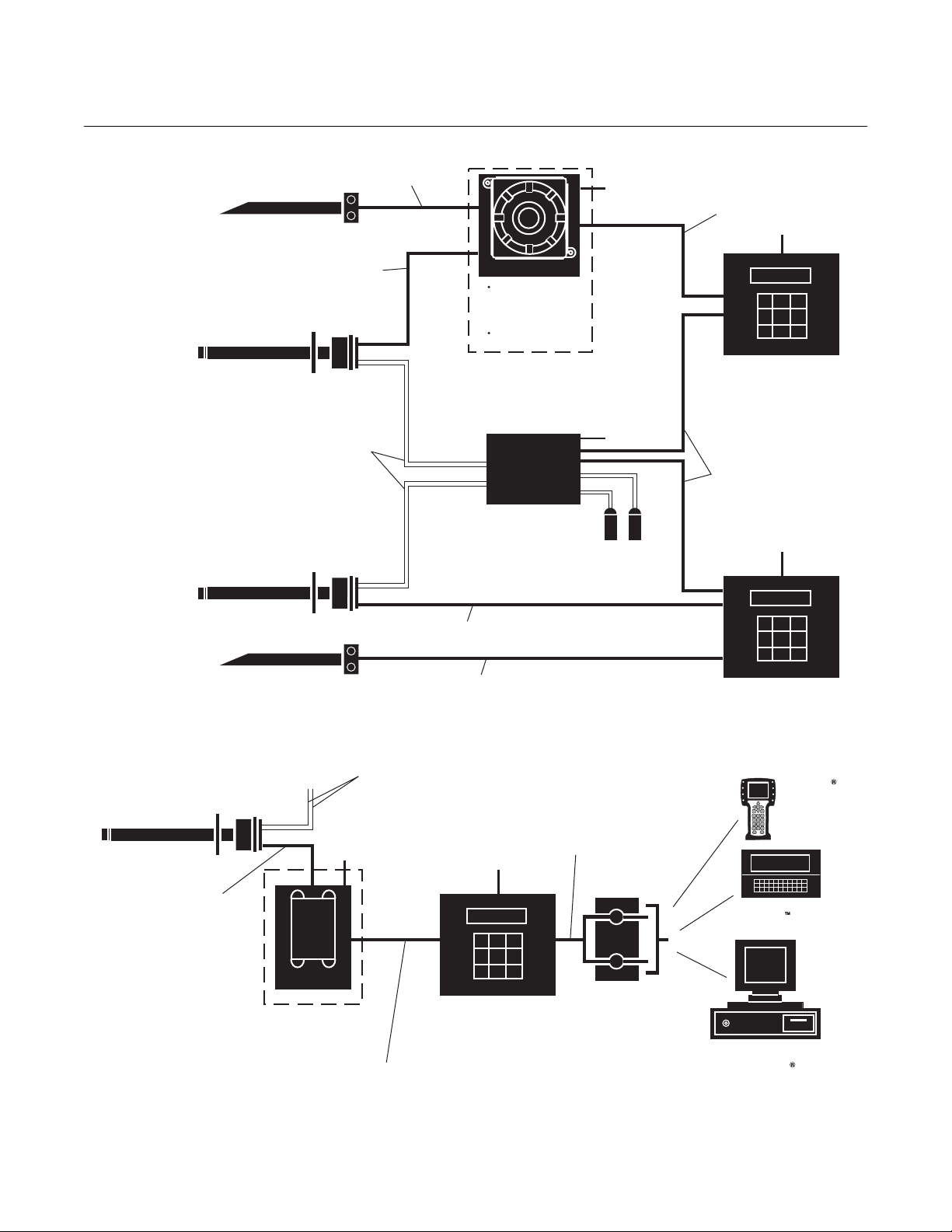
Stack Thermocouple
(optional)
World Class 3000
Probe
2-Calibration Gas Lines
World Class 3000
Probe
Wire [150 Ft (45 m) Max]
7-Conductor Cable
[150 Ft (45 m) Max]
by Customer
[300 Ft (90 m) Max]
2-Conductor T/C
(optional)
(HPS not required for lengths of less than 150 feet)
7-Conductor Cable
[150 Feet (45 m) Max]
(OPTIONAL)
HPS 3000
Explosion Proof
Required only for
Hazardous Area
Applications, otherwise
use NEMA 4X.
Lengths Exceeding
150 ft (45 m).
(OPTIONAL)
MPS 3000
CALIBRATION GAS
SEQUENCER
Modular Design
Up to 4 Probes
Line Voltage
Line Voltage
Calibration Gas
by
Customer
4 Twisted Pair Plus 2 Twisted Pair
for Options [1200 Ft (364 m) Max]
Line Voltage
IFT 3000
Intelligent Field Transmitter
NEMA 4X Enclosure
Line Voltage
100 to 120 Volt
220 to 240 Volt
5 Conductor
[1000 Ft (309 m) Max]
Line Voltage
World Class 3000
Probe
7-Conductor Cable
[150 Ft (45 m) Max]
Stack Thermocouple
(optional)
Line Voltage
HPS 3000
Heater Power Supply
Required for > 150 Ft (45 m)]
[Optional,
4 Twisted Pair, plus 2 Twisted Pair
for Options [1200 Ft (364 m) Max]
2-Calibration Gas Lines
by Customer
[300 Ft (90 m) Max]
2-Conductor T/C
Wire [150 Feet (45 m) Max]
(optional)
Line Voltage
IFT 3000
Intelligent Field Transmitter
NEMA 4X Enclosure
Line Voltage
100 to 120 Volt
220 to 240 Volt
4-20 mA Output
(Twisted Pair)
Termination in
Control Room
Figure 1-3. World Class 3000 Typical Application with Intelligent Field Transmitters
IFT 3000
Intelligent Field Transmitter
NEMA 4X Enclosure
Line Voltage
100 to 120 Volt
220 to 240 Volt
HART
Model 275/375
Handheld
Communicator
Customer's Laptop with
Cornerstone Software
Customer's Distributed
Control System
with HART
Interface Capability
37840001
1-6 Description and Specifications Rosemount Analytical Inc. A Division of Emerson Process Management
Page 35

World Class 3000
Instruction Manual
IB-106-300NH Rev. 4.3
May 2005
After selecting the probe mounting location,
provision should be made for a platform
where the probe can be easily serviced.
The intelligent field transmitter (IFT) can be
located up to 150 ft (45 m) cabling distance
from the probe when used without optional
heater power supply (HPS). When the system includes the optional HPS, the HPS can
be located up to 150 ft (45 m) cabling distance from the probe and the IFT may be
located up to 1200 ft (364 m) cabling distance from the HPS.
A source of instrument air is required at the
probe for reference air use. Since the probe
is equipped with an in-place calibration
feature, provision should be made for con-
necting calibration gas tanks to the oxygen
analyzer when the probe is to be calibrated.
If the calibration gas bottles will be permanently hooked up, a check valve is required
next to the calibration fittings on the probe
junction box. This is to prevent breathing of
calibration gas line and subsequent flue gas
condensation and corrosion. The check
valve is in addition to the stop valve in the
calibration gas kit or the solenoid valve in
the multiprobe calibration gas sequencer
units.
An optional Z-purge arrangement is available for applications where hazardous area
classification may be required (See Application Data Bulletin AD 106-300B).
Rosemount Analytical Inc. A Division of Emerson Process Management Description and Specifications 1-7
Page 36

Instruction Manual
IB-106-300NH Rev. 4.3
May 2005
World Class 3000
1-8 Description and Specifications Rosemount Analytical Inc. A Division of Emerson Process Management
Page 37

World Class 3000
Instruction Manual
IB-106-300NH Rev. 4.3
May 2005
SECTION 2
INSTALLATION
2-1 OXYGEN ANALYZER (PROBE)
INSTALLATION
Before starting to install this equipment, read the "Safety instructions for
wiring and installation of this apparatus" at the front of this Instruction
Manual. Failure to follow the safety instructions could result in serious injury or death.
a. Selecting Location
1. The location of the probe in the stack
or flue is most important for maximum
accuracy in the oxygen analyzing process. The probe must be positioned so
that the gas it measures is representative of the process. Best results are
normally obtained if the probe is positioned near the center of the duct (40
to 60% insertion). A point too near the
edge or wall of the duct may not provide a representative sample because
of the possibility of gas stratification. In
addition, the sensing point should be
selected so that the process gas temperature falls within a range of 50° to
1300°F (10° to 704°C). Figure 2-1 provides mechanical installation
references.
4. If the probe is to be mounted outside,
subject to rain and snow conditions,
make sure the back of the probe (outside of the duct) is insulated to prevent
the formation of flue gas condensate in
the calibration gas lines.
Do not allow the temperature of the
probe junction box to exceed 300°F
(149°C) or damage to the unit may result. If the probe junction box temperature exceeds 300°F (149°C), the user
must fabricate a heat shield or provide
adequate cooling air to the probe junction box.
b. Mechanical Installation
1. Ensure that all components are available for installation of the probe. Ensure that the system cable is the
required length. If equipped with the
optional ceramic diffusor element, ensure that it is not damaged.
2. The probe may be installed intact as it
is received. It is recommended that you
disassemble the adapter plate for each
installation.
NOTE
2. Check the flue or stack for holes and
air leakage. The presence of this condition will substantially affect the accuracy of the oxygen reading. Therefore,
either make necessary repairs or install
the probe upstream of any leakage.
3. Ensure that the area is clear of obstructions internal and external that will
interfere with installation. Allow adequate clearance for removal of probe
(Figure 2-1).
Rosemount Analytical Inc. A Division of Emerson Process Management Installation 2-1
An abrasive shield is recommended
for high velocity particulate in the flue
stream (such as those in coal fired
boilers, kilns, and recovery boilers).
Vertical and horizontal brace clamps
are provided for 9 ft and 12 ft (2.75 m
and 3.66 m) probes to provide mechanical support of the probe. Refer to
Figure 2-1, sheet 5.
3. Weld or bolt adapter plate (Figure 2-1)
onto the duct.
Page 38

Instruction Manual
IB-106-300NH Rev. 4.3
May 2005
World Class 3000
9
Y
D IN - XIT
FURNISHE
ADAPTER &ACCESSOR
0.062 THK GASKET
POSED
INSULATE IF EX
4512C34
4512C35
3535B18H02
3635B48H01
ANSI
JIS
TO AMBIENT
WEATHERCONDITIONS
4512C36
3535B45H01
DIN
2.27 (58)
DIA MAX
REF AIR
UBE
1/4 IN. T
6 MM TUBE
ANSI
DIN
6 MM TUBE
JIS
RSIN
ACTURED
D ARENOT
UF
2727000
CAL GAS
CHES WITH MILLIMETE
1/2"
ELEC
CONN
OPE
NT
OU
EM
ROS
5.85 (148.6)
AL ENVEL
REMOV
7.58 (192)
DIM "B"
CONDUIT
1.88 (48)
GAS
CAL
AIR
REF
OM
OTT
AT THE B
BOTTOM VIEW
ONS AREININ
DIMENSI
T PATTERNS AN
TED.
THESE FLATFACED FLANGES ARE MAN
TO ANSI,DIN, ANDJIS BOL
PARENTHESES.
PRESSURE RA
2.
INSTALL WITH CONNECTIONS
NOTES: 1.
DIM "A"
SNUBBER
DIFFUSER
WITH STANDARD
BE
CERAMIC
3.80 (96.5)
FOR PRO
WITH
ADD TODIM "A"
OR
CERAMIC
DIFFUSER
4.90(124.5)
ARRESTOR
ADD TODIM "A" F
DIFFUSER AND FLAME
PROBE WITH
18H01
JIS
6.10
(155)
(15)
5.12
0.59
(130)
4512C
DIN
7.28
(185)
(18)
0.71
5.71
4512C19H01
AL
(145)
DIM "B"
27.3(694)
81.3 (2065)
45.3(1151)
117.3(2980)
153.3 (3894)
0.75
(20)
4.75
(121)
16(406)
34 (864)
18 IN.
3 FT
70 (1778)
6 FT
106 (2692)
9FT
142 (3607)
12 FT
DIM "A"
TABLE II INSTALLATION/REMOV
PROBE
OWMUST
ANSI
OUNTING FLANGE
6.00
(153)
4512C17H01
TO
4848G01
TABLE I M
DIRECTION
OR 353
RESPECT
FLANGE
HOLE
DIA.
DIA.
(4) HOLES
EQ SPONBC
PROCESS FL
BE IN THIS
WITH
DEFLECT
Figure 2-1. Probe Installation (Sheet 1 of 5)
2-2 Installation Rosemount Analytical Inc. A Division of Emerson Process Management
Page 39

World Class 3000
7.50
7.48
0.75
9.25 (235)
*
JIS
7.48
0.945
9.25 (235)
*
DIN
* FLANGES ARE MANUFACTURED TO ANSI,
TABLE IV. FLANGE SIZE
BOLT
CIRCLE
0.75
(8) HOLES
DIAMETER
FLANGE
9.00 (153)
DIAMETER
*
ANSI
DIN, AND JIS BOLT PATTERNS AND ARE
FLAT FACED. THESE FLANGES ARE NOT
PRESSURE RATED.
5.7
(145)
14.5
(369)
DIM "D" REMOVAL ENVELOPE
7.00
(178)
Instruction Manual
IB-106-300NH Rev. 4.3
May 2005
REF AIR AND
CAL GAS
CONNECTOR
ELECTRICAL
CONNECTOR
CAL GAS LINES
CHECK VALVE FOR
37840002
31.1
(790)
45.3
(1151)
DIM "D" DIM "E"
27
(686)
DIM "C"
NOMINAL MEASUREMENTS
TABLE III. REMOVAL / INSTALLATION
3FT
67.1
81.3
63
6FT
(1704)
117.3
(2065)
99
(1600)
103.1
(2619)
(2980)
(2515)
9FT
139.1
(3533)
153.3
(3894)
135
(3429)
12 FT
DIM "E" (WITH FLAME ARRESTOR)
IN HARDWARE PACKAGE
DIM "C"
0.06 THK GASKET FURNISHED
(P/N 3535B58G04 - JIS)
(P/N 3535B58G02 - ANSI)
SEE TABLE IV
FOR FLANGE
SIZES
(P/N 3535B58G06 - DIN)
NOMINAL
3.6 (91.44)
(P/N 4843B38G02)
SNUBBER DIFFUSION/
DUST SEAL ASSEMBLY
INSULATE IF
CONDITIONS
EXPOSED TO
AMBIENT WEATHER
DIMENSIONS ARE IN INCHES WITH
MILLIMETERS IN PARENTHESES.
NOTE:
Figure 2-1. Probe Installation (Sheet 2 of 5)
Rosemount Analytical Inc. A Division of Emerson Process Management Installation 2-3
Page 40

Instruction Manual
IB-106-300NH Rev. 4.3
May 2005
JIS
(P/N 3535B58G04)
9.25
(235)
4.92
(125)
(M-20 x 2.5)
(200)
7.894
World Class 3000
16860021
8 THREADED HOLES
EQUALLY SPACED ON
D DIA B.C.
ABRASIVE SHIELD
FLANGE O.D.
TABLE VI. ADAPTOR PLATE DIMENSIONS FOR ABRASIVE SHIELD
DIN
ANSI
IN.
DIMENSIONS
JIS
9.25
(P/N 3535B58G06)
9.00
(P/N 3535B58G02)
"A"
(mm)
6.50
(P/N 4512C35G01)
(235)
(229)
(165)
3.94
(100)
4.75
(121)
"B"
DIA
(M-12 x 1.75)
(M-16 x 2)
0.625-11
"C"
THREAD
(130)
5.118
7.48
7.50
"D"
(190)
(191)
DIA
ATTACHING HARDWARE.
NOTE: PART NUMBERS FOR ADAPTOR PLATES INCLUDE
o
22.5
A
OUTSIDE WALL SURFACE.
CROSSHATCHED AREA IN 4
CORNERS MAY BE USED TO
FIELD BOLTING OF PLATE TO
PROVIDE ADDITIONAL HOLES FOR
Y
AND 12 FT ABRASIVE SHIELD
ADAPTOR PLATE FOR 3, 6, 9,
INSTALLATIONS. SEE SHEET 2.
QUALL
C
A
B
4 STUDS,
SPACED ON
LOCKWASHERS AND
C DIA B.C.
NUTS E
B
ADAPTOR PLATE FOR
STD WORLD CLASS 3000
PROBE INSTALLATION.
SEE SHEET 1.
TABLE V. ADAPTOR PLATE DIMENSIONS FOR PROBE
DIN
ANSI
IN.
DIMENSIONS
7.5
(P/N 4512C36G01)
6.00
(P/N 4512C34G01)
"A"
(mm)
(191)
(153)
(M-16 x 2)
0.625-11
"B"
THREAD
(145)
5.708
4.75
(121)
"C"
DIA
A
o
45
A
C
ATTACHING HARDWARE.
2.500 DIA
NOTE: PART NUMBERS FOR ADAPTOR PLATES INCLUDE
Figure 2-1. Probe Installation (Sheet 3 of 5)
2-4 Installation Rosemount Analytical Inc. A Division of Emerson Process Management
Page 41

World Class 3000
INSTALLATION FOR METAL
WALL STACK OR DUCT
CONSTRUCTION
Instruction Manual
IB-106-300NH Rev. 4.3
May 2005
INSTALLATION FOR MASONRY
WALL STACK CONSTRUCTION
MTG HOLES
SHOWN ROTATED
o
45 OUT OF
TRUE POSITION
WELD OR BOLT ADAPTOR
PLATE TO METAL WALL
OF STACK OR DUCT.
JOINT MUST BE AIR TIGHT.
0.50 (13)
3.75 (95)
MIN DIA HOLE
IN WALL
STACK OR DUCT
METAL WALL
0.50 (13)
BOLT ADAPTOR
PLATE TO OUTSIDE
WALL SURFACE
FIELD WELD
PIPE TO
ADAPTOR PLATE
MTG HOLES
SHOWN ROTATED
o
45 OUT OF
TRUE POSITION
JOINT MUST
BE AIRTIGHT
OUTSIDE WALL
SURFACE
NOTE: ALL MASONRY STACK WORK AND JOINTS EXCEPT
ADAPTOR PLATE NOT FURNISHED BY ROSEMOUNT
ANALYTICAL.
4.50 (114)
O.D. REF
PIPE 4.00 SCHED 40
PIPE SLEEVE (NOT
BY ROSEMOUNT
ANALYTICAL
LENGTH BY CUSTOMER
MASONRY
STACK WALL
)
WELD OR BOLT ADAPTOR
PLATE TO METAL WALL
OF STACK OR DUCT.
JOINT MUST BE AIR TIGHT.
2.50 (63.5)
MIN DIA HOLE
IN WALL
STACK OR DUCT
METAL WALL
BOLT ADAPTOR
PLATE TO OUTSIDE
WALL SURFACE
JOINT MUST
BE AIRTIGHT
OUTSIDE WALL
SURFACE
NOTE: DIMENSIONS IN INCHES WITH
MILLIMETERS IN PARENTHESES.
FIELD WELD
PIPE TO
ADAPTOR PLATE
3.50 (89)
O.D. REF
PIPE 3.00 SCHED 40
PIPE SLEEVE (NOT BY
ROSEMOUNT
ANALYTICAL
BY CUSTOMER
MASONRY
STACK WALL
) LENGTH
37840004
Figure 2-1. Probe Installation (Sheet 4 of 5)
Rosemount Analytical Inc. A Division of Emerson Process Management Installation 2-5
Page 42

Instruction Manual
IB-106-300NH Rev. 4.3
May 2005
o
60 MAX.
BRACE BARS
(NOT BY ROSEMOUNT
ANALYTICAL)
2.00
(51)
1.00
(25)
World Class 3000
NOTE: DIMENSIONS IN INCHES WITH
MILLIMETERS IN PARETHESES.
VERTICAL BRACE CLAMP ASSY.
HORIZONTAL BRACE CLAMP ASSY.
(BOTH BRACE CLAMP ASSEMBLIES ARE THE SAME.
INSTALLATION AND LOCATION OF CLAMP ASSEMBLIES
AND BRACE BARS TO BE DONE IN FIELD.)
BY ROSEMOUNT
}
ANALYTICAL
o
30 MIN.
4.12
(105)
4.12
(105)
2 HOLES - 0.625
(16) DIA. FOR
0.50 (12) DIA.
BOLT
0.375
(10)
1.00
(25) MAX.
NOTE: BRACING IS FOR VERTICAL AND HORIZONTAL PROBE INSTALLATION.
EXTERNAL BRACING REQUIRED FOR 9 FT AND 12 FT
(2.75 M AND 3.66 M) PROBES AS SHOWN ABOVE.
5.62
(143)
5.62
(143)
36.00 (914)
ABRASIVE SHIELD
Figure 2-1. Probe Installation (Sheet 5 of 5)
37840005
2-6 Installation Rosemount Analytical Inc. A Division of Emerson Process Management
Page 43

World Class 3000
Instruction Manual
IB-106-300NH Rev. 4.3
May 2005
4. If using the optional ceramic diffusor
element, the vee deflector must be correctly oriented. Before inserting the
probe, check the direction of flow of the
gas in the duct. Orient the vee deflector
on the probe so that the apex points
upstream toward the flow (Figure 2-2).
This may be done by loosening the
setscrews, and rotating the vee deflector to the desired position.
Retighten the setscrews.
5. In horizontal installations, the probe
junction box should be oriented so that
the system cable drops vertically from
the probe junction box. In a vertical installation, the system cable can be oriented in any direction.
6. If the system has an abrasive shield,
check the dust seal packings. The
joints in the two packings must be
staggered 180°. Also, make sure that
the packings are in the hub grooves as
the probe slides into the 15° forcing
cone in the abrasive shield.
NOTE
7. Insert probe through the opening in the
mounting flange and bolt the unit to the
flange. When probe lengths selected
are 9 or 12 ft (2.75 or 3.66 m), special
brackets are supplied to provide additional support for the probe inside the
flue or stack. See Figure 2-1, sheet 5.
NOTE
Probe Installation
To maintain CE compliance, ensure
there is a good connection between
the chassis of the probe and earth.
GAS FLOW
DIRECTION
VEE
DEFLECTOR
APEX
DIFFUSION
ELEMENT
SETSCREW
FILTER
VEE
DEFLECTOR
If process temperatures will exceed
392°F (200°C), use anti-seize compound on stud threads to ease future
removal of probe.
624017
Figure 2-2. Orienting the Optional Vee Deflector
Rosemount Analytical Inc. A Division of Emerson Process Management Installation 2-7
Page 44
Instruction Manual
IB-106-300NH Rev. 4.3
May 2005
World Class 3000
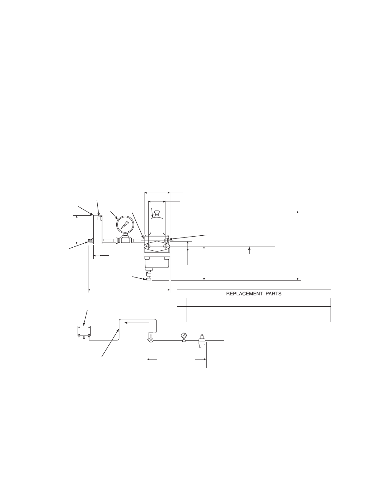
c. Reference Air Package
After the oxygen analyzing (probe) unit is
installed, connect the reference air set to
the probe junction box. The reference air
set should be installed in accordance with
Figure 2-3.
d. Service Required
1. Power input: 100, 115 or 220 Vac single phase, 50 to 60 Hz, 3 amp minimum. (See label.)
2. Compressed air: 10 psig (68.95 kPa)
minimum, 225 psig (1551.38 kPa)
0.125-27 NPT FEMALE
OUTLET CONNECTION
1
4.81 (122.17)
FLOW SET
POINT KNOB
2
OUTLET
1.19
(30.22)
DRAIN VALVE
maximum at 2 scfh (56.6 L/hr) maximum; supplied by one of the following
(less than 40 parts-per-million total hydrocarbons). Regulator outlet pressure
should be set at 5 psi (35 kPa).
(a) Instrument air - clean, dry.
(b) Bottled standard air with step-down
regulator.
(c) Bottled compressed gas mixture
(20.95% oxygen in nitrogen).
(d) Other equivalent clean, dry, oil-free
air supply.
3.12 (79.25) MAX
3
2.250 (57.15)
2.0
(50.80)
1.50
(38.10)
0.25-18 NPT FEMALE
INLET CONNECTION
NOTE: DIMENSIONS ARE IN INCHES WITH
2 MOUNTING HOLES
3.19 (81.03) LG
THROUGH BODY FOR
0.312 (7.92) DIA BOLTS
MILLIMETERS IN PARENTHESES.
8.50 MAX
(215.90)
10.0 REF
0.250 OR 6 MM OD
TUBE COMPRESSION
FITTING (SUPPLIED BY WECO)
0.250 OR 6 MM OD TUBING
(SUPPLIED BY CUSTOMER)
SCHEMATIC HOOKUP FOR REFERENCE AIR SUPPLY ON OXYGEN ANALYZER PROBE HEAD.
(254)
TO PROBE HEAD
1 FLOWMETER 0.2-2.0 SCFH 771B635H02
2 2" PRESSURE GAGE 0-15 PSIG 275431-006
3 COMBINATION FILTER-REG. 0-30 PSIG 4505C21G01
REF AIR SET
263C152G01
COMPRESSED AIR SUPPLY
10-225 PSIG MAX PRESSURE
27270003
Figure 2-3. Air Set, Plant Air Connection
2-8 Installation Rosemount Analytical Inc. A Division of Emerson Process Management
Page 45
World Class 3000
Instruction Manual
IB-106-300NH Rev. 4.3
May 2005
2-2 INTELLIGENT FIELD TRANSMITTER (IFT)
INSTALLATION
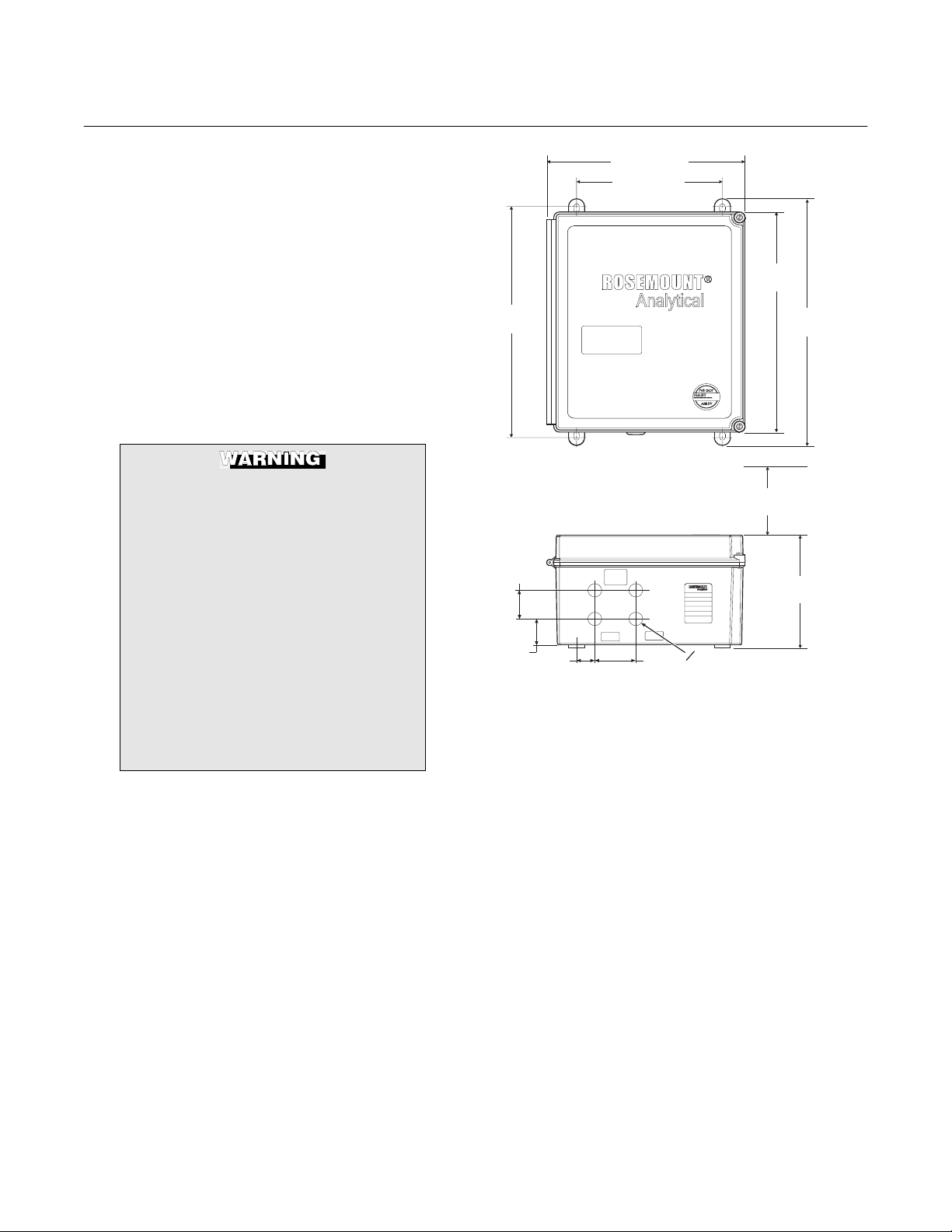
a. Mechanical Installation
The outline drawing of the IFT module in
Figure 2-4 shows mounting centers and
clearances. The NEMA 4X enclosure is designed to be mounted on a wall or bulkhead. The IFT should be installed no more
than 1200 feet (364 m) from the optional
HPS or 150 feet (45 m) from the probe if
HPS is not installed in the system.
b. Electrical Connections
To meet the Safety Requirements of
IEC 1010 (EC requirement), and ensure
safe operation of this equipment, connection to the main electrical power
supply must be made through a circuit
breaker (min 10A) which will disconnect all current carrying conductors
during a fault situation. This circuit
breaker should also include a mechanically operated isolating switch. If
not, then another external means of
disconnecting the supply from the
equipment should be located close by.
Circuit breakers or switches must
comply with a recognized standard
such as IEC 947.
NOTE
Refer to Figure 2-6 for fuse locations
and specifications.
1. The IFT can be configured for 100,
120, 220, or 240 line voltages. For 120
Vac usage, install JM8, JM7, and JM1
on the power supply board. For 220
Vac usage, install jumpers JM6, JM5,
JM2 (refer to Figure 2-5 and Figure
2-6).
11.00 (279.4)
8.00 (203.2)
12.50
(317.5)
13.10
(332.7)
11.0 (279.4) MINIMUM DOOR
SWING CLEARANCE
1.62
(41.1)
1.49
(37.8)
NOTE: DESIGN DIMENSIONS ARE IN INCHES
1.00
(25.4)
WITH MILLIMETERS IN PARENTHESES.
ALLCABLESHOULD
BERATEDFOR USE
LINE
NOTICE:
ABOVE76 C
(57.15)
PROBE
2.25
ModelIFT
Assy6A00178GXX
SNXXXXXXXXXXXX
VoltsXXX @ 50/60 Hz
LineFuse 5Amps
RosemountAnalyticalInc.
P.O.Box901, Orrville, OH
44667USA
0.867
0
(22.00)
14.00
(355.6)
6.40
(162.6)
37840020
Figure 2-4. Outline of Intelligent Field Transmitter
be configured to connect directly to a
probe. An optional HPS is available for
cable runs over 150 feet (45 m). The
electrical connections for a non-HPS
equipped system should be made as described in the electrical installation diagram, Figure 2-7. Refer to Figure 2-13
for connections for an HPS equipped
system.
2. For installations where the cable run is
less than 150 feet (45 m), the IFT can
Rosemount Analytical Inc. A Division of Emerson Process Management Installation 2-9
Page 46

Instruction Manual
IB-106-300NH Rev. 4.3
May 2005
Do not install jumper JM6 on the microprocessor board, or JM1 on the interconnect board, if an HPS is
installed in the system. This will result
in system failure.
World Class 3000
if MPS is installed in the system. Refer
to Figure 2-7, note 6.
5. The power cable should comply with
the safety regulations in the user's
country and should not be smaller than
16 gauge, 3 amp.
3. The IFT must have JM6 on the microprocessor board (Figure 2-8 and Figure
2-9) and JM1 on the interconnect
board (Figure 2-10 and Figure 2-11)
installed if an HPS is not installed in
the system.
4. If an MPS is not used in the system,
wire jumper between CAL RET and
NO GAS must be installed on the interconnect board. Remove wire jumper
CONFIGURATION
LINE VOLTAGE
SELECTION
100 V.A.C.
120 V.A.C.
220 V.A.C.
240 V.A.C.
JUMPER
(INSTALL)
JM3, JM7, JM2
JM8, JM7, JM1
JM6, JM5, JM2
JM6, JM5, JM1
ALWAYS DISCONNECT LINE VOLTAGE
JUMPER
REPLACEMENT" PROBE (115V)
FROM INTELLIGENT FIELD TRANSMITTER
BEFORE CHANGING JUMPERS.
PROBE HEATER
VOLTAGE SELECTION
WORLD CLASS PROBE (44V)
218 PROBE (115V)
WORLD CLASS "DIRECT
6. Before supplying power to the IFT, verify that the jumpers have been properly
set in the IFT (Figure 2-5, Figure 2-8,
and Figure 2-10).
7. Terminal strip J5 on the power supply
board is used for supplying the IFT with
power. Terminal strip J6 on the power
supply board is used to supply the
probe heater with power if an HPS is
not used (Figure 2-6).
JUMPER
(INSTALL)
JM10
JM9
JM9
21190012
If incorrect heater voltage is selected, damage to the probe may occur. For HPS voltage selection jumper, refer to Figure 2-15. Always update the relevant labeling to reflect the set
voltage.
Figure 2-5. Power Supply Board Jumper Configuration
2-10 Installation Rosemount Analytical Inc. A Division of Emerson Process Management
Page 47

World Class 3000
FUSES
Instruction Manual
IB-106-300NH Rev. 4.3
May 2005
FUSES
NOTE: ALL FUSES (F1 THROUGH F5)
ARE 5A @ 250 VAC, ANTISURGE, CASE SIZE5X20MM,
TYPE T TO IEC127, SCHURTER.
Figure 2-6. IFT Power Supply Board Jumpers
Rosemount Analytical Inc. A Division of Emerson Process Management Installation 2-11
Page 48

Instruction Manual
IB-106-300NH Rev. 4.3
May 2005
World Class 3000
PROBE JUNCTION
BOX WIRING
HEATER
GN CELL -VE
OR CELL +VE
YE CHROMEL
RD ALUMEL
}
GN
BK
BK
123456 78
BL
YE
RD
OR
PROBE TC +
PROBE TC -
PROBE MV -
PROBE MV +
WORLD CLASS
PROBE
BK
GN
WH
E
H
R
NOTES:
STACK TC WIRING AS REQUIRED.
SPECIAL PROBE CABLE BETWEEN PROBE
AND IFT BY ROSEMOUNT ANALYTICAL.
INSTALL JM1 ON INTERCONNECT BOARD.
INSTALL JM6 ON MICROPROCESSOR
BOARD PER FIGURE 2-8.
IF STACK TEMPERATURE NOT USED.
IF MPS 3000 NOT USED.
1 RELAY PER PROBE AVAILABLE FOR
CALIBRATION STATUS INDICATION. (48 V
max, 100 mA max)
CURRENT/VOLTAGE SELECTOR SWITCH
MUST BE SELECTED TO CURRENT (I) FOR
HART COMMUNICATIONS APPLICATIONS.
SET SWITCH SW3A PER FIGURE 2-8.
SWITCH/JUMPER CONFIGURATION FOR REV.
10
13 AND LATER
INTELLIGENT FIELD TRANSMITTER IFT 3000
J1
JM6
J3
J2
3D39513G, REV 13
MICROPROCESSOR
BOARD
10
J2
3D39120G REV
INTERCONNECT BOARD
J3
LINE
VOLTAGE
SECTION
100 V.A.C.
120 V.A.C.
220 V.A.C.
240 V.A.C.
JUMPER CONFIGURATION
JUMPER
(INSTALL)
JM3, JM7, JM2
JM8, JM7, JM1
JM6, JM5, JM2
JM6, JM5, JM1
J1
3D39122G REV
POWER SUPPLY BOARD
ALWAYS DISCONNECT LINE VOLTAGE
FROM INTELLIGENT FIELD TRANSMITTER
BEFORE CHANGING JUMPERS.
PROBE HEATER
VOLTAGE SECTION
WORLD CLASS PROBE
218 PROBE
WORLD CLASS "DIRECT
REPLACEMENT" PROBE
JUMPER
(INSTALL)
JM10
JM9
JM9
J4
2 CONDUCTOR
J5
SHIELDED CABLE
CAL RET
NO GAS
LO GAS
HI GAS
IN CAL
SHIELD
5 CONDUCTOR SHIELDED CABLE
PER PROBE #16 AWG BY CUSTOMER
PROBE 2 PROBE 3 PROBE 4
IN CAL
HI GAS
NO GAS
CAL RET
LOW GAS
GND
STUD
J5 J6
L
H
EN
LINE
VOLTAGE
BK
WH
GN
PU
OR
BL
YE
RD
ER
PROBE 1
LINE OUT LINE IN
J10
L
N
HI GAS
IN CAL
NO GAS
CAL RET
LOW GAS
NC C NO NC C NO NC C NO NC C NO
J11
PROBE 1
PROBE 2 PROBE 3 PROBE 4
MPS 3000 MULTIPROBE CALIBRATION GAS SEQUENCER (OPTIONAL)
MPS TERMINATION BOARD
BY CUSTOMER
J6
J7
SHIELD
STACK TC STACK TC +
J8
SHIELD
PROBE TC -
RD
YE
PROBE TC +
J9
SHIELD
BL
PROBE MV
MV+
PROBE
OR
IN CAL
HI GAS
NO GAS
CAL RET
LOW GAS
PROBE 2
PROBE 3
SOLENOID
PROBE 1
SOLENOID
J13 J14 J15 J16 J17 J18
SW2
CURRENT/VOLTAGE
SELECTOR SWITCH
J1
AOUT -
AOUT +
-
IN CAL
HI GAS
NO GAS
CAL RET
PROBE 4
HIGH GAS
SOLENOID
SOLENOID
SOLENOID
D
C
B
A
ON OFF
JM1
LOW GAS
GAS
LOW
SOLENOID
SW3
PRESSURE
J12
L
N
SWITCH
L
LINE
E
VOLTAGE
N
37840006
Figure 2-7. Wiring Layout for IFT Systems without HPS
2-12 Installation Rosemount Analytical Inc. A Division of Emerson Process Management
Page 49

World Class 3000
Instruction Manual
IB-106-300NH Rev. 4.3
May 2005
OUTPUT JUMPER
HPS Remove JM6
Probe (No HPS) Install JM6
ANALOG OUTPUT
(Condition during
microcontroller failure) Switch SW3
Output = zero SW3 on
Output = maximum SW3 off
(See Figure 2-9 for jumper and switch locations.)
Figure 2-8. Microprocessor Board
Jumper Configuration
c. Analog Output and Relay Output
Connections
1. The microprocessor board has a selector for voltage or current operations.
Figure 2-9 shows switch orientation. In
voltage mode, output is 0-10 V. In the
current mode, the output can be configured from the SETUP menu to be 020 mA or 4-20 mA.
2. The analog output and relay outputs
are programmed by the user as
needed. The analog output is typically
sent to recording equipment such as
chart recorders. Relay outputs are typically sent to annunciators.
3. Relays K1 and K2 are user configurable from the probe SETUP sub-menu
(Table 5-5). Typically these are used to
indicate O
specified tolerances. OK relay is energized when unit is functioning properly.
4. All wiring must conform to local and
national codes.
5. Analog output requires shielded cable
with the shield terminated at the interconnect board.
6. Connect the analog output and relay
outputs as shown in Figure 2-11.
2-3 HEATER POWER SUPPLY INSTALLATION
a. Mechanical Installation
The outline drawing of the heater power
supply enclosure in Figure 2-12 shows
mounting centers and clearances. The
NEMA 4X enclosure is designed to be
mounted on a wall or bulkhead. The heater
power supply should be installed no further
than 150 feet (45 m) from the probe. The
heater power supply must be located in a
location free from significant ambient temperature changes and electrical noise. Ambient temperature must be between -20°
and 140°F (-30° and 60°C).
values above or below
2
Rosemount Analytical Inc. A Division of Emerson Process Management Installation 2-13
Page 50

Instruction Manual
IB-106-300NH Rev. 4.3
May 2005
World Class 3000
JUMPER
JM6
IFT CPU BOARD
3D39513G
R117
J1
TP36
R10
R18
R29
C14
D2
TP10
R2
D1
TP9 TP20
U11
R28
TP7
Q2 C6 D6
R24
C2
U10
C15
R20
J2
J3
JM6
R97
TP8
TP55
TP59
TP29
C27
TP36
TP19
TP51
U2
R40
D7 D6
D5
C42
G1
R111
R129
C17
C48
C62
Q10
TP92
TP56
U21
TP61
U15
R72
R67
R36
C16
Q4
Y1
U28
R112
R99
C46
C51
C45
R113
R106
R102
U34Q9C80
C81
Q11
TP3
TP1
R79
R106
U19
TP62
C25
C34
U14
R50
TP40
JM8
R159
C19
TP71
TP65
C52
TP63
TP67
D13
D12
TP94
TP91
TP85
C53
TP90
Q12
R69
R160
TP57
TP93
TP81
TP102
U29
TP97
R110
D19
R127
C50
R114
C55
R124
TP103
TP130
R115
TP96
D17
TP95
REV
U24
C39
U16
C36
C40
R77
TP63
U9
C29
TP101
C64
R121
C12
R87
U23
TP2
R122
R120
U28
R85
Z2
Q13
R123
Z4
D18
TP99
R116
TP84
C54
R119
Q8
R104 R100
R126
R118
TP33
C78
R92
TP75
D11
U20
C9
R125
TP96
U30
TP73
R88
U27
R86
R107
C47
C48
R95
TP85
TP77
U22
U18
U1
U8
U3
U5
U33
R161
TP105
U6
R153
R156
R98
TP89
TP72TP82
R85
R103
SW2
U25
R109
C83
TP78
R101
R83
C8
TP79
TP76
R91
SWITCH
SW3
EMERSOM PROCESS MANAGEMENT / RAI
TP5 TP6
SW3
R152
C74
R150
TP22
Q15
Z6
R149
Q14
C75
R157
D20
TP80
C59
R93
RL1
C56
R145
R26 R22
C73
U31
R144
C10
R147
R23
R142
R141
R139
R156
C85
D14
C72
U7
R27 R32
R136
R140
C86
R135
R131
R133
C87
R43
R132
R136
R137
C71
D16
RL3
C58
R90
R105
C23
U32
R19
Z5
C20
C11
R154
TP104
R143
R155
C76
C77
Y2
TP4
C70
D3
C89
R134
C88
C4
RL2
C57
R6
C5
Q1
C7
D4
R5
R4
R1
D15
T2
R102
J4
37840031
CURRENT VOLTAGE
SELECTOR SWITCH
SW2
Figure 2-9. IFT Microprocessor Board
2-14 Installation Rosemount Analytical Inc. A Division of Emerson Process Management
Page 51

World Class 3000
Figure 2-10. Interconnect Board Jumper Configuration
NOTES:
DENOTES SHIELD CONNECTION.
OK RELAY IS ENERGIZED WHEN
UNIT IS FUNCTIONING PROPERLY.
OUTPUT JUMPER
HPS Remove JM1
Probe (No HPS) Install JM1
OK-NC
K1-NC
K2-NC
CAL INIT-2
CAL INIT-1
CALRET
NOGAS
LOGAS
HIGAS
INCAL
RELAY
RELAY+
AD590
AD590+
TRIAC
TRIAC+
Instruction Manual
IB-106-300NH Rev. 4.3
May 2005
24
24
23
22
21
20
19
18
17
16
15
14
13
12
11
10
9
8
-
7
6
5
-
4
3
2
-
1
OK-COM
OK-NO
23
22
K1-COM
K1-NO
21
K2-COM
20
19
K2-NO
18
17
16
15
14
13
12
ANOUT-
11
ANOUT+
10
9
STACK T/C
8
STACK T/C
7
6
PROBE T/C
5
4
PROBE T/C
3
2
PROBE MV
1
PROBE MV+
-
JM1
(UNDER
SHIELD)
16860010
Figure 2-11. IFT Interconnect Board Output Connections
Rosemount Analytical Inc. A Division of Emerson Process Management Installation 2-15
Page 52
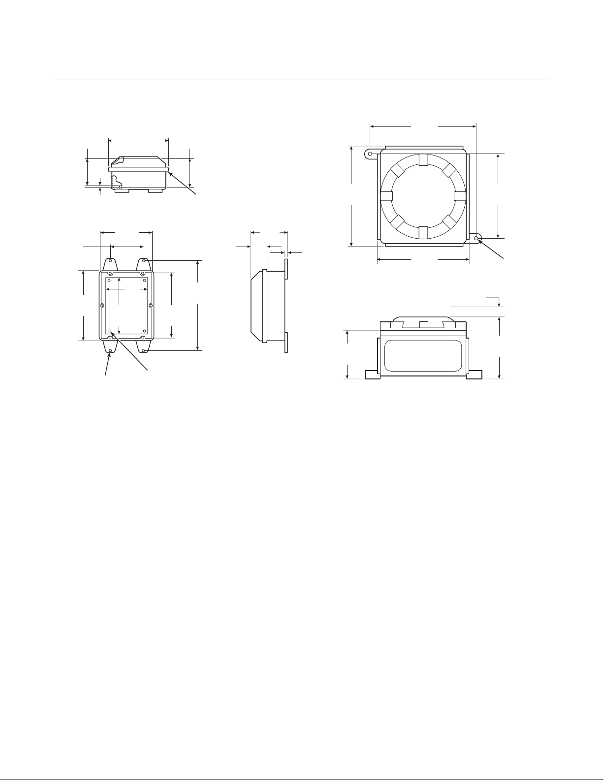
Instruction Manual
IB-106-300NH Rev. 4.3
May 2005
World Class 3000
4.00
(101.6)
(215.9)
3.25
(82.6)
8.50
0.31
(7.9)
#0.31
6.00
(152.4)
4.88
(124)
6.75
(171.5)
NOTE: DIMENSIONS IN INCHES
7.00
(177.8)
#10-32 UNF 2A
THREADED INSERT
(0.31 x 0.31 FROM CORNER OF PLATE)
WITH MILLIMETERS IN PARENTHESES.
3.63
8.00
(203.2)
(92.2)
11.00
(279.4)
NEMA 4X
(NON-HAZARDOUS)
0.13" (3.3) THK U. L. APPROVED
GASKET
1.81
(46)
4.38
(111.3)
10.39
(264)
9.96
(253)
0.38
(9.7)
1.00 (25.4) MINIMUM CLEARANCE
4.72
(120)
CLASS 1, DIVISION 1, GROUP B ENCLOSURE
FOR REMOVING COVER
9.17
(233)
8.50
(215.9)
6.18
(156.9)
0.56 (14)
DIA (2)
MOUNTING
HOLES
686029
Figure 2-12. Outline of Heater Power Supply
b. Electrical Connections
1. Electrical connections should be made
as described in the electrical installation diagram, Figure 2-13. The wiring
terminals are divided into two layers;
the bottom (FROM PROBE) terminals
should be connected first, the top
(FROM ELECTRONICS) terminals
should be connected last (Figure 2-14).
Each terminal strip has a protective
cover which must be removed when
making connections. To remove the
terminal covers, remove two slotted
screws holding cover in place. Always
reinstall terminal covers after making
connections. All wiring must conform to
local and national codes.
NOTE
Refer to Figure 2-16 for fuse locations
and specifications.
2. Power Input: 120, 220 or 240 Vac. For
120 Vac usage, install jumpers JM4
and JM1. For 220 or 240 Vac usage,
install jumper JM5 (see label, Figure
2-15).
NOTE
For 100 Vac usage, the heater power
supply is factory-supplied with a different transformer. When using the
HPS with 100 Vac transformer, install
jumpers JM1 and JM4.
3. The power cable should comply with
safety regulations in the user's country
and should not be smaller than 16
gauge, 3 amp.
2-16 Installation Rosemount Analytical Inc. A Division of Emerson Process Management
Page 53

World Class 3000
Instruction Manual
IB-106-300NH Rev. 4.3
May 2005
PROBE JUNCTION
BOX WIRING
HEATER
GN CELL -VE
OR CELL +VE
YE CHROMEL
RD ALUMEL
123456 78
BL
YE
RD
OR
PROBE MV -
PROBE MV +
PROBE TC +
PROBE TC -
}
GN
BK
BK
BK
GN
WH
E
H
R
WORLD CLASS PROBE
LINE VOLTAGE
SELECTION
120 V.A.C./100 V.A.C.
11
220/240 V.A.C.
PROBE HEATER
VOLTAGE SECTION
WORLD CLASS PROBE JM7
TOP
TRIAC RELAY
J9
+
+++
-
CONFIGURATION
JUMPER
(INSTALL)
JM4, JM1
JM5
JUMPER
(INSTALL)
2
1
STACKTCANALOG
---
NOTES:
RELAY WIRE IS OPTIONAL, RELAY CAN BE BYPASSED
1
WITH JUMPER JM-2 IF NOT WIRED TO THE IFT.
STACK TC WIRING AS REQUIRED.
2
ALL WIRES #16-#22 AWG TWISTED PAIR WITH SHIELD
3
BY CUSTOMER EXCEPT AS NOTED.
STANDARD PROBE CABLE BETWEEN PROBE AND
4
HPS BY ROSEMOUNT ANALYTICAL.
REMOVE JM1 ON INTERCONNECT BOARD.
5
INSTALL JM6 ON MICROPROCESSOR
6
BOARD PER FIGURE 2-8.
IF RELAY WIRE OF NOTE 1 INSTALLED THEN
7
REMOVE JM2 ON HPS 3000.
IF STACK TEMPERATURE NOT USED.
8
IF MPS 3000 NOT USED.
9
1 RELAY PER PROBE AVAILABLE FOR CALIBRATION
10
STATUS INDICATION (48 V max, 100 mA max).
100 V.A.C. REQUIRES TRANSFORMER PART
11
NUMBER 1M02961G02.
ALWAYS DISCONNECT LINE VOLTAGE
JUMPER
FROM HEATER POWER SUPPLY
BEFORE CHANGING JUMPERS.
HEATER
POWER
REMOTE
ON
ELECTRONICS
SELECTION
(NEXT GENERATION)
HEATER
BK
WH
ON
REMOVE JM2
INSTALL JM2
JUMPER
REMOVE JM3, JM6DIGITAL
7
1
2 TWISTED PAIR SHIELDED
#22 AWG BY CUSTOMER
(OPTIONAL)
A
B
37840007
4
OR CELL+
BL CELL -
YE HTR TC +
RD HTR TC
WH
BK
GN
-
GN/YE
(INTERNAL
AD590
+
-
WIRING)
-
PROBE
PROBE
TC
MV
J8
+
-
BOTTOM
PROBE
J3
+
STACK
2
J2 J1
+
MV
PROBE
TC
+
-
PROBE
TC
HEATER
RH
-
HPS 3000 INTERFACE MODULE
WHBK
4 TWISTED PAIR SHIELDED
#22 AWG BY CUSTOMER
LINE
L
N
LINE
VOLTAGE
Figure 2-13. Wiring Layout for Complete IFT 3000 System with HPS (Sheet 1of 2)
Rosemount Analytical Inc. A Division of Emerson Process Management Installation 2-17
Page 54

Instruction Manual
IB-106-300NH Rev. 4.3
May 2005
World Class 3000
INTELLIGENT FIELD TRANSMITTER IFT 3000
J1
6
JM6
D
C
B
A
ON OFF
SW3
LINE
VOLTAGE
SECTION
100 V.A.C.
120 V.A.C.
200 V.A.C.
220 V.A.C.
240 V.A.C.
GND
STUD
JUMPER
(INSTALL)
JM3, JM7, JM2
JM8, JM7, JM1
JM4, JM5, JM2
JM6, JM5, JM2
JM6, JM5, JM1
J5 J6
L
LINE
VOLTAGE
J1
ALWAYS DISCONNECT LINE VOLTAGE
FROM INTELLIGENT FIELD TRANSMITTER
BEFORE CHANGING JUMPERS.
JUMPER CONFIGURATION
PROBE HEATER
VOLTAGE SECTION
NOT USED REMOVE
NOT USED
EN
3D39122G REV
POWER SUPPLY BOARD
JUMPER
(INSTALL)
JM9, JM10
CAL RET
NO GAS
LO GAS
HI GAS
IN CAL
SHIELD
RELAY –
RELAY +
SHIELD
AD590 –
AD590 +
SHIELD
TRIAC –
TRIAC +
J3
J2
3D39513G, REV 13
MICROPROCESSOR
BOARD
J2
J3
J4
J5
J6
J7
SHIELD
STACK TC STACK TC +
J8
SHIELD
PROBE TC -
RD
YE
PROBE TC +
J9
SHIELD
BL
PROBE MV
PROBE
OR
CURRENT/VOLTAGE
SELECTOR SWITCH
10
J1
3D39120G REV
INTERCONNECT BOARD
2 CONDUCTOR
SHIELDED CABLE
BY CUSTOMER
8
-
MV+
AOUT AOUT +
SW2
JM1
A
B
5 CONDUCTOR SHIELDED CABLE
PER PROBE #16 AWG BY CUSTOMER
PROBE 1
LINE OUT LINE IN
J10
L
N
HI GAS
IN CAL
NO GAS
CAL RET
NC C NO NC C NO NC C NO NC C NO
J11
PROBE 1
PROBE 2 PROBE 3 PROBE 4
MPS 3000 MULTIPROBE CALIBRATION GAS SEQUENCER (OPTIONAL)
PROBE 2 PROBE 3 PROBE 4
LOW GAS
HI GAS
IN CAL
NO GAS
CAL RET
LOW GAS
IN CAL
HI GAS
NO GAS
CAL RET
PROBE 2
PROBE 1
SOLENOID
J13 J14 J15 J16 J17 J18
MPS TERMINATION BOARD
LOW GAS
SOLENOID
PROBE 3
HI GAS
SOLENOID
IN CAL
PROBE 4
CAL RET
SOLENOID
HIGH GAS
NO GAS
SOLENOID
LOW GAS
GAS
LOW
SOLENOID
L
N
SWITCH
PRESSURE
J12
L
LINE
E
VOLTAGE
N
37840008
Figure 2-13. Wiring Layout for Complete IFT 3000 System with HPS (Sheet 2 of 2)
2-18 Installation Rosemount Analytical Inc. A Division of Emerson Process Management
Page 55

World Class 3000
TRANSFORMER
SCREW
(2 PER COVER)
Instruction Manual
IB-106-300NH Rev. 4.3
May 2005
TERMINAL
COVERS
FRONT
TERMINAL STRIP
(FROM ELECTRONICS)
TRANSFORMER
(FROM ELECTRONICS)
SIDE
Figure 2-14. Heater Power Supply Wiring Connections
TERMINAL STRIP
29850005
Rosemount Analytical Inc. A Division of Emerson Process Management Installation 2-19
Page 56

Instruction Manual
IB-106-300NH Rev. 4.3
May 2005
LINE VOLTAGE
SELECTION
1
100/120 VAC
220/240 VAC
JUMPER
(INSTALL)
JM4, JM1
JM5
JUMPER
CONFIGURATIONS
World Class 3000
ALWAYS DISCONNECT LINE VOLTAGE
FROM HEATER POWER SUPPLY AND
ANALOG ELECTRONICS (IF USED)
BEFORE CHANGING JUMPERS.
HEATER
POWER
REMOTE
ON
JUMPER
REMOVE JM2
*INSTALL JM2
2
PROBE HEATER
VOLTAGE SELECTION
WORLD CLASS PROBE
218 PROBE (115V)
(44V)
NOTES:
1
100 VAC OPERATION REQUIRES TRANSFORMER PART
NUMBER 1M02961G02.
2
REFER TO TABLE 3-5 FOR PROPER SET POINT SELECTION.
JUMPER
(INSTALL)
JM7
JM8
Figure 2-15. Jumper Selection Label
NOTE
Before supplying power to the heater
power supply, verify that jumpers JM3,
JM6 are removed and JM7 is installed.
If relay wire (Figure 2-13, note 1) is installed, JM2 must be removed from
HPS Mother Board (Figure 2-16).
4. Before supplying power to the heater
power supply, verify that the jumpers
on the mother board, Figure 2-16, are
properly configured. Jumpers JM3 and
JM6 should be removed and JM7
should be installed.
Additionally, make sure that the proper
jumper for your line voltage is installed,
Figure 2-15. If relay wire (Figure 2-13,
note 1) is not installed, JM 2 should be
installed on the HPS Mother Board
(Figure 2-16).
NOTE
ELECTRONICS
SELECTION
*ANALOG (EXISTING)
DIGITAL
(NEXT GENERATION)
FUSES
JM1
JM2
JM4
JM7
FUSE
JUMPER
INSTALL JM3, JM6
REMOVE JM3, JM6
37840009
JM5
3D3 080G REV
Refer to Figure 2-8 and Figure 2-10 for
proper IFT jumper configuration. IFT
microprocessor and interconnect
board jumper configurations must be
set correctly in order for HPS to work
properly.
2-20 Installation Rosemount Analytical Inc. A Division of Emerson Process Management
NOTE: ALL FUSES ARE 5A @ 250 VAC,
ANTI-SURGE, CASE SIZE
5 X 20 MM, TYPE T TO IEC127,
SCHURTER.
29850001
Figure 2-16. Jumpers on HPS Mother Board
Page 57

World Class 3000
Instruction Manual
IB-106-300NH Rev. 4.3
May 2005
2-4 MULTIPROBE CALIBRATION GAS
SEQUENCER INSTALLATION
a. Mechanical Installation
The outline drawing of the MPS module in
Figure 2-17 shows mounting centers and
clearances. The box is designed to be
mounted on a wall or bulkhead. The MPS
module should be installed no further than
300 feet (91 mz) piping distance from the
probe, and no more than 1000 feet (303 m)
cabling distance from the IFT. Install the
MPS module in a location where the ambient temperature is between -20° and 160°F
(-30° and 71°C).
12.00
(304.80)
10.00
(254.00)
b. Gas Connections
Figure 2-18 shows the bottom of the MPS
where the gas connections are made. 1/4
inch threaded fittings are used.
1. Connect the reference air supply to
INSTR. AIR IN. The air pressure regulator valve is set at the factory to 20 psi
(138 kPa). If the reference air pressure
should need readjustment, turn the
knob on the top of the valve until the
desired pressure is obtained.
2. Connect the high O
calibration gas to
2
HIGH GAS. The calibration gas pressure should be set at 20 psi (138 kPa).
Analytical
14.00 (355.60) REF
PROBE1 PROBE 2 PROBE 3 PROBE4
LOWCAL
CALGAS
HIGHCAL
GASIN
INSTR
AIR
CALGAS
GASIN
OUT
REFAIR
REFAIR
OUT
Figure 2-17. MPS Module
12.00
(304.80)
NOTE: DIMENSIONS ARE IN INCHES
WITH MILLIMETERS IN
PARENTHESES.
CALGAS
CALGAS
OUT
OUT
OUT
REFAIR
REFAIR
OUT
OUT
OUT
0.84 (21.34)
1.96 (49.78)
3.09 (78.49)
4.21 (106.93)
5.25 (133.35)
5.54 (140.72)
37840010
Rosemount Analytical Inc. A Division of Emerson Process Management Installation 2-21
Page 58

Instruction Manual
IB-106-300NH Rev. 4.3
May 2005
World Class 3000
3. Connect the low O2 calibration gas to
LOW GAS. The calibration gas pressure should be set at 20 psi (138 kPa).
4. Connect the REF AIR OUT to the reference air fitting on the probe junction
box.
5. Connect the CAL GAS OUT to the
calibration gas fitting on the probe
junction box.
6. If the MPS is configured for multiple
probes (up to four), repeat steps 4 and
5 for each additional probe.
A check valve is required for each
probe connected to an MPS to prevent
condensation of flue gas in the calibration gas lines. The check valve
must be located between the calibration fitting and the gas line.
c. Electrical Connections
Electrical connections should be made as
described in the electrical installation diagram, Figure 2-19. All wiring must conform
to local and national codes. The electrical
connections will exist only between the
electronics package and the MPS to enable
automatic and semiautomatic calibration. If
more than one probe system is being used,
the additional probes and electric packages
would be wired similar to the first probe.
NOTE
Refer to Figure 2-19 for fuse locations
and specifications.
1. Run the line voltage through the bulkhead fitting on the bottom of the MPS
where marked LINE IN, Figure 2-18.
Connect the line voltage as shown in
Figure 2-19 to the LINE IN terminal on
the MPS termination board located inside the unit. Tighten the cord grips to
provide strain relief.
2. The MPS can accommodate up to four
probes. The terminal strips on the MPS
termination board are marked PROBE
1, PROBE 2, PROBE 3, and PROBE 4.
Select PROBE 1 if this is the first probe
and electronic package installed on the
MPS.
3. Make the connections from the MPS to
the IFT as shown in Figure 2-19. Run
wires from the MPS Termination Board
inside the unit through the bulkhead fitting on the bottom of the unit where
marked SIGNAL IN, Figure 2-18. After
the connections are made, tighten the
cord grips to provide strain relief.
LINE IN
PROBE 1 PROBE 2 PROBE 3 PROBE4
LOW CAL
CAL GAS
CAL GAS
CAL GAS
OUT
REF AIR
OUT
CAL GAS
OUT
REF AIR
OUT
SIGNAL IN
27270014
DRAIN
HIGH CAL
GAS IN
INSTR
GAS IN
OUT
OUT
REF AIR
REF AIR
OUT
OUT
AIR
Figure 2-18. MPS Gas Connections
2-22 Installation Rosemount Analytical Inc. A Division of Emerson Process Management
Page 59
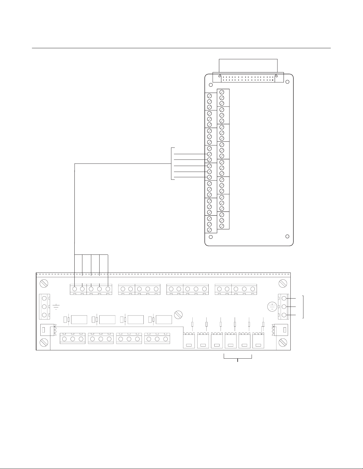
World Class 3000
NOTE: FUSES FOR 115 VOLT MPS UNIT ARE
FAST ACTING, 1A @ 250 VAC,
SIZE: 1/4 IN. DIA X 1-1/4 IN. LG.,
GLASS BODY, NON-TIME DELAY,
BUSSMAN PART NO. BK/AGC-1
(ROSEMOUNT ANALYTICAL PART NO.
138799-004).
FUSES FOR 220 VOLT MPS UNIT ARE
FAST ACTING, 0.5 A @ 250 VAC,
SIZE 1/4 IN. DIA. X 1-1/4 IN. LG.,
GLASS BODY, NON-TIME DELAY,
BUSSMAN PART NO. BK/AGC-1/2
(ROSEMOUNT ANALYTICAL PART NO.
138799-014).
INTERCONNECT
IFT
BOARD
CAL RET
NO GAS
LO GAS
HI GAS
IN CAL
MH1
Instruction Manual
IB-106-300NH Rev. 4.3
May 2005
J1
J2
J3
J4
J5
J6
J7
MH2
3D39120G REV
J8
J9
MH3
MH4
PROBE 1 PROBE 2 PROBE 3 PROBE 4
LINE OUT LINE IN
L
IN CAL
HI GAS
N
CAL RET
NO GAS
LOW GAS
HI GAS
IN CAL
CAL RET
J10
NC C NO NC C NO NC C NO NC C NO
J11
PROBE 1
PROBE 2 PROBE 3 PROBE 4
NO GAS
LOW GAS
PROBE 3
SOLENOID
HI GAS
IN CAL
PROBE 4
IN CAL
HI GAS
NO GAS
CAL RET
LOW GAS
PROBE 2
SOLENOID
PROBE 1
SOLENOID
J13 J14 J15 J16 J17 J18
CAL RET
SOLENOID
NO GAS
HIGH GAS
SOLENOID
LOW GAS
LOW GAS
SOLENOID
L
N
SWITCH
PRESSURE
J12
MPS TERMINATION BOARD
FUSES LOCATED BEHIND
TERMINATION BOARD
Figure 2-19. MPS Probe Wiring
L
LINE
E
VOLTAGE
N
37840011
Rosemount Analytical Inc. A Division of Emerson Process Management Installation 2-23
Page 60
Instruction Manual
IB-106-300NH Rev. 4.3
May 2005
NOTE
Upon completing installation, make sure that the probe is turned on and operating prior to
firing up the combustion process. Damage can result from having a cold probe exposed to
the process gases.
Power down all probes during outages. Sensor chamber is heated to 736°C. Further, if ducts
will be washed down during the outage, remove the probes to prevent water damage.
World Class 3000
2-24 Installation Rosemount Analytical Inc. A Division of Emerson Process Management
Page 61

World Class 3000
Instruction Manual
IB-106-300NH Rev. 4.3
May 2005
SECTION 3
SETUP
3-1 OVERVIEW
This section provides information on configuring
the IFT 3000 Intelligent Field Transmitter. This
section assumes that you are familiar with the
operation of the IFT and the General User Interface (GUI). If you need additional information
on operating the IFT or using the GUI, refer to
Section 5, General User Interface (GUI)
Operation.
3-2 CONFIGURING THE ANALOG OUTPUT
Use the following procedure to configure the
analog output.
a. Press the SETUP key on the GUI keypad.
b. Set the Source to the desired measurement
value to be represented by the analog output. The choices are O
Rng O
.
2
, Efficiency, or Dual
2
c. Set the Type to the desired output signal
style. The choices are HART 4-20mA,
0-20mA, and 0-10V. The choice selected
must agree with the position of the
current/voltage selector switch on the IFT
microprocessor board. An invalid choice will
be discarded. Note that if you are using
HART to communicate with the IFT, you
must set the analog output type to HART
4-20mA.
d. The next choice, Range Setup, will vary
based on the source selected.
3. Source Set to Dual Rng O
. Range
2
setup allows you to set the transfer
function (Xfer Fnct) to either linear or
log output. You can also specify the O
values represented by the high and low
analog output values for both the normal and high range.
The Mode Setup sub-menu contains
entries for setting the range mode,
whether the high range is used during
calibration, and the point at which the
output switches from normal to high
range.
For a complete description of all parameters associated with configuring
the analog output, refer to Table 5-5.
3-3 SETTING CALIBRATION PARAMETERS
To successfully calibrate a World Class 3000
system, several calibration parameters must be
set. These parameters are generally set once
and left at those values. These values should
only be changed if the system is not calibrating
properly, or when changing test gas bottles.
a. Press the SETUP key on the GUI keypad.
b. Select the Calibration sub-menu.
c. Set the High Gas parameter to the oxygen
concentration of the high calibration gas.
For high calibration gas, 8% oxygen with a
balance of nitrogen is recommended.
2
1. Source set to Efficiency. No range
setup is allowed when the source is set
to efficiency. Analog output range is
fixed at 0-100% efficiency.
2. Source set to O
. Range setup allows
2
you to set the transfer function (Xfer
Fnct) to either linear or log output. You
can also specify the O
values repre-
2
sented by the high and low analog output values.
Rosemount Analytical Inc. A Division of Emerson Process Management Setup 3-1
d. Set the Low Gas parameter to the oxygen
concentration of the low calibration gas. For
low calibration gas, 0.4% oxygen with a
balance of nitrogen is recommended.
e. The Auto Cal parameter determines
whether the IFT performs automatic or
semiautomatic calibrations. In order to perform automatic calibration, the system must
be equipped with an MPS 3000 Multiprobe
Calibration Gas Sequencer. To perform
Page 62

Instruction Manual
IB-106-300NH Rev. 4.3
May 2005
World Class 3000
automatic calibrations, set the Auto Cal parameter to Yes.
f. The Output Tracks setting determines
whether the analog output tracks the oxygen reading during a calibration. Setting
Output Tracks to No locks the analog output
value to the last measured oxygen reading
until the calibration is complete.
g. The Cal Interval parameter sets the time in
hours and days between automatic calibrations. When Auto Cal is set to NO, this parameter is set to OFF.
h. The Next Cal parameter displays the time
until the next scheduled automatic calibration. If automatic calibration is not enabled,
this parameter displays Disabled.
i. The Gas Time parameter sets the amount
of time that calibration gas flows during an
automatic calibration before a reading is
taken. This value is not used for semiautomatic calibrations.
alarms, respectively. The Alarm DB parameter
allows the setting of an alarm dead band. When
a dead band is set, the O
value must change
2
by the dead band value before the alarm will reset. For example, if the Hi Alarm is set to 8.00%
and the dead band is set to 0.25%, the O
centration must drop to below 7.75% before the
O
alarm will clear. This prevents the alarms
2
from continually activating and clearing when
the oxygen value is near the alarm setpoint.
3-5 CONFIGURING EFFICIENCY
CALCULATIONS
To enable efficiency calculations and set the efficiency constants, press the SET UP key on
GUI keypad, and select the Efficiency Calc submenu. The Enable Calc selection turns efficiency calculation on and off. Enter the K1, K2,
and L3 constant values in the appropriate fields.
Efficiency constant values are listed in Table 5-6
for oil and gas for the US and Europe.
3-6 CONFIGURING THE RELAY OUTPUTS
con-
2
j. The Purge Time parameter sets the amount
of time after an automatic calibration before
the system is returned to normal operation.
This allows time for the calibration gases to
clear the lines and the system to return to
the process gas concentration. This value is
not used for semiautomatic calibrations.
k. The Res Alarm parameter displays the set-
point for the Res Hi alarm. Do not change
this parameter unless directed by a qualified
Rosemount Analytical Service Engineer.
l. Press the ESC key twice to return to the
Main menu.
3-4 SETTING THE O
The IFT has a high and low O
ALARM SETPOINTS
2
alarm. To
2
change the alarm setpoints, press the SETUP
key on the GUI keypad and select the O
Alarms sub-menu.
The Hi Alarm and Lo Alarm values are the settings for the high and low oxygen concentration
The IFT has two relays that can be individually
configured. Each relay can be triggered by three
separate events selected from a list of eight
events. Use the following procedure to configure
the relay outputs.
a. Press the SETUP key on the GUI keypad.
Select the Relay Outputs sub-menu.
b. Select K1 Setup or K2 Setup to configure
relay one or relay two, respectively.
c. Set Event 1, Event 2, and Event 3 to the
desired triggering event. The relay will be
energized when any of the three events occurs. If you do not want a relay to trigger on
three events, set the desired trigger or triggers and set the remaining events to Off.
Note that the TG Low event will only function if the system includes an MPS 3000
Multiprobe Test Gas Sequencer.
2
d. Press the ESC key and select the other re-
lay. Configure the relay as described above.
e. Press the ESC key three times to return to
the Main menu.
3-2 Setup Rosemount Analytical Inc. A Division of Emerson Process Management
Page 63

World Class 3000
Instruction Manual
IB-106-300NH Rev. 4.3
May 2005
SECTION 4
CALIBRATION
4-1 ANALOG OUTPUT CALIBRATION
For the analog output to perform within the published specifications, it must be manually calibrated. The only equipment needed to perform
the calibration is a voltage or current meter, depending on which mode of operation is to be
calibrated. Prior to manual calibration, remove
the IFT from any control loops it may be in.
Prior to manual calibration, the IFT
should be removed from any automatic control loops. Failure to remove
the IFT from control loops prior to
calibration may result in faulty equipment performance.
Once initiated from the Setup - Analog Outputs
menu, the calibration procedure is self guiding.
4-2 SYSTEM CALIBRATION
a. Overview
The primary purpose of an oxygen analyzer
is to give an accurate representation of the
percentage of O
system should be calibrated periodically to
maintain an accuracy which may otherwise
be reduced over time due to cell aging. A
calibration record sheet is provided at the
end of this section to track cell performance.
A requirement for calibration is a set of two
accurate calibration gases spanning the
oxygen range of most interest. For example,
0.4% and 8% for a 0-10% oxygen range.
Under normal conditions the probe should
not need frequent calibration. Because calibration is necessary, the system can be
equipped with the optional MPS 3000 Multiprobe Calibration Gas Sequencer for fully
automatic calibration at regular intervals.
Without an MPS, the probes must be calibrated manually (semiautomatically).
in the gas stream. The
2
b. Probe Calibration
1. Previous Calibration Constants
Functionality
There are three sets of registers used
to store calibration constants. These
are: Latest Calibration, Previous Calibration, and Calculation. Only the values in the Calculation register are used
to calculate the oxygen value for display and representation on the analog
output signal. These values may be
changed in two ways.
(a) The operator may change the val-
ues through the SETUP menu. The
operator may adjust the slope and
constant individually, or reset both
to the values calculated during the
last good calibration. To reset the
values, move the cursor to RESET
SLOPE & CONST and push
ENTER.
(b) The IFT will automatically change
the values after each calibration as
follows:
The values in the Latest Calibration registers are updated after
every complete calibration, even if
the calibration is not successful. If
the calibration is successful, the
values in the Latest Calibration
registers are copied into the Previous Calibration registers. This is
accomplished prior to the update of
the Latest Calibration registers.
The new slope and constant are
copied into the Calculation register.
If the calibration fails, the Previous
Calibration registers retain their
existing values, while the Latest
Calibration registers record the
values of the failed calibration. The
Calculation register is not updated
when the calibration fails.
Rosemount Analytical Inc. A Division of Emerson Process Management Calibration 4-1
Page 64

Instruction Manual
IB-106-300NH Rev. 4.3
May 2005
World Class 3000
2. Calibration Methods
There are three calibration methods:
manual (semiautomatic), manually initiated automatic, and fully automatic.
Manual (semiautomatic) calibration is
done without an MPS unit. Calibration
gases are switched on and off by the
operator and the IFT is sequenced
through the calibration procedure by
the operator with the front panel keyboard. The IFT prompts the operator
for the correct action. Manually initiated
automatic calibration is done with an
MPS. The operator manually initiates
the calibration at the IFT or through a
remote switch, and the IFT controls the
operation of the MPS unit and the calibration sequencing. Fully automatic
calibration requires no action from the
operator. The setup is the same as
semiautomatic except the IFT automatically initiates the calibration at a
fixed calibration interval. In this mode
the operator can also manually initiate
calibrations between the intervals in
the same manner as semiautomatic
calibrations.
c. Manual (Semiautomatic) Calibration
1. Calibration Gases For Manual
(Semiautomatic) Calibration
There are two options for supplying
calibration gases to the probe during
semiautomatic calibration. The first "A"
uses refillable bottles and adjustable 2stage pressure regulators; the second
"B" uses disposable bottles and a fixed
single stage regulator to provide a
mixed flow. Normally, the first (method
"A") will have a higher cost and not be
portable. The second ("B") is less
costly, portable, and weighs about 10
lbs (4.5 kg).
Test Method "A" Fixed Tanks and
Manifolds
(a) Required Equipment
Do not use 100% nitrogen as a zero
gas. It is suggested that gas for the
zero be between 0.4% and 2.0% O2. Do
not use gases with hydrocarbon concentrations of more than 40 parts per
million. Failure to use proper gases
will result in erroneous readings.
NOTE
Ambient air is not recommended for
use as high calibration gas. An 8% O
balance in nitrogen is recommended
for high calibration gas.
1 Two tanks of precision cali-
bration gas mixtures. Recommended calibration gases
are nominally 0.4% and 8.0%
oxygen in nitrogen.
Two sources of calibrated gas
mixtures are:
LIQUID CARBONIC GAS
CORP.
SPECIALTY GAS
LABORATORIES
700 South Alameda Street
Los Angeles, California
90058
213/585-2154
767 Industrial Road
San Carlos, California 94070
415/592-7303
9950 Chemical Road
Pasadena, Texas 77507
713/474-4141
12054 S.W. Doty Avenue
Chicago, Illinois 60628
312/568-8840
2
603 Bergen Street
Harrison, New Jersey 07029
201/485-1995
4-2 Calibration Rosemount Analytical Inc. A Division of Emerson Process Management
Page 65
World Class 3000
Instruction Manual
IB-106-300NH Rev. 4.3
May 2005
255 Brimley Road
Scarborough, Ontario,
Canada
416/266-3161
SCOTT ENVIRONMENTAL
TECHNOLOGY, INC.
SCOTT SPECIALTY
GASES
2600 Cajon Blvd.
San Bernardino, CA 92411
714/887-2571
TWX: 910-390-1159
1290 Combermere Street
Troy, MI 48084
314/589-2950
Route 611
Plumsteadville, PA 18949
215/766-8861
TWX: 510-665-9344
2616 South Loop, West
Suite 100
Houston, TX 77054
713/669-0469
2 If gas bottles will be perma-
nently hooked up to the
probe, a manual block valve is
required at the probe (between the calibration fitting
and the gas line) to prevent
the migration of process
gases down the calibration
gas line.
If an MPS 3000 Multiprobe
Gas Sequencer is used, a
check valve is required at the
probe.
3 Two, 2-stage pressure regu-
lators with stainless steel diaphragms for tanks. Maximum
output required: 20 psi (138
kPa).
4 One instrument air pressure
regulator: 20 psi (138 kPa)
maximum and a supply of
clean, dry instrument air.
5 Two zero-leakage shutoff
valves.
6 Miscellaneous oil-free tubing
and fittings.
(b) Calibration
1 A typical calibration setup is
shown in Figure 4-1. Care
must be taken that all fittings
are tight and free from oil or
other organic contaminants.
Small openings can cause
back diffusion of oxygen from
the atmosphere even though
positive pressures are maintained in the lines.
NOTE
The probe calibration gas fitting has a
seal cap which must be in place at all
times except during calibration.
In addition to the precision
calibration gas mixtures,
clean, dry, oil-free instrument
air should be used for
calibration.
For optimum accuracy, this calibration
should be run with the process at
normal temperature and operating
conditions.
When the calibration gas line
exceeds 6 ft (1.8 m) in length
from the leak tight valves,
check valve, Rosemount
Analytical P/N 6292A97H02,
should be installed next to the
calibration gas connection on
the probe to prevent breathing
of the line with the process
gas and subsequent gas condensation and corrosion.
Rosemount Analytical Inc. A Division of Emerson Process Management Calibration 4-3
Page 66

Instruction Manual
IB-106-300NH Rev. 4.3
May 2005
World Class 3000
PROBE
(END VIEW)
CALIBRATION
IN-PLACE
FITTING
CHECK
FLOW METER
LEAK TIGHT
VALVES
0.4% O
VALV E
2
Figure 4-1. Typical Calibration Setup
NOTE
Only set the calibration gas flowmeter
upon initial installation and after
changing the diffusion element. A
slightly lower calibration gas flow rate
may indicate a plugged diffusion
element.
2 Set the calibration gas pres-
sure regulators and the flow
meter for a flow of 5 SCFH at
20 psi (138 kPa) for both
gases. The reference air
should be flowing as in normal
operation.
3 Refer to paragraph 4-2d of
this section for Manual (Semiautomatic) Calibration setup
and procedure using the IFT.
4 Calibration gases will be
switched on and off using the
shutoff valves.
NOTE: PROBE CALIBRATION GAS FITTING
REFERENCE AIR
HAS A SEAL CAP WHICH MUST
BE IN PLACE AT ALL TIMES
EXCEPT DURING CALIBRATION.
CONNECTION
8.0% O
2
2 SCFH
REFERENCE
AIR SET
INSTR.
AIR
IN
37840014
Test Method "B" Oxygen Calibration
Gas and Service Kit.
(a) Required Equipment
Do not use 100% nitrogen as a zero
gas. It is suggested that gas for the
zero be between 0.4% and 2.0% O2. Do
not use gases with hydrocarbon concentrations of more than 40 parts per
million. Failure to use proper gases
will result in erroneous readings.
NOTE
Ambient air is not recommended for
use as high calibration gas. An 8% O
balance in nitrogen is recommended
for high calibration gas.
1 Portable Oxygen Calibration
Gas Kits (Figure 4-2), Rosemount Analytical P/N
6296A27G01, containing 8%
and 0.4% gases in a portable
carrying case with regulator,
built-in valve, hose and connecting adapter to the calibration gas connection.
2
4-4 Calibration Rosemount Analytical Inc. A Division of Emerson Process Management
Page 67

World Class 3000
CALIBRATION
GAS KIT #1
(P/N 6296A27G01)
Analytical
37840018
Instruction Manual
IB-106-300NH Rev. 4.3
May 2005
Rosemount France
165 Boulevard de Vallmy
92706, Colombes, France
Rosemount Analytical P/N
3530B07G01 for probe 0.4%
oxygen in nitrogen in disposable bottle.
Rosemount Analytical P/N
3530B07G02 for probe 8%
oxygen in nitrogen in disposable bottle.
3 A check valve is required at
the probe (between the calibration fitting and the gas line)
to prevent the migration of
process gases down the calibration gas line.
(b) Calibration with a Portable Rose-
mount Analytical Oxygen Calibration Gases Kit.
Figure 4-2. Portable Rosemount Analytical
Oxygen Calibration Gas Kit
2 Extra gas bottles are available
at:
Rosemount Analytical Inc.
6565 Davis Industrial Parkway
Solon, OH 44139-3922
U.S.A.
Rosemount Limited
Burymead Road
Hitchin, Herts. U.K.
Rosemount Italy
VIA Guido Cavalcanti 8
20127 Milan, Italy
Rosemount Spain
Saturnino Calleja 6
28002 Madrid
Spain
1 A typical portable calibration
setup is shown in Figure 4-3.
For manual (semiautomatic)
calibration, remove cap plug
from the calibrate in place fitting. The cap plug must be
retained to seal this fitting after calibration is complete;
failure to do so may render
the probe useless if the system pressure is slightly negative. The reference air should
be flowing as in normal
operation.
2 Refer to paragraph 4-2.d of
this section for Manual (Semiautomatic) Calibration setup
and procedure using the IFT.
3 Screw the pushbutton regu-
lator with contents gage on to
the calibration gas of choice
and inject the calibration gas
by opening the valve. Gas is
on continuously when the
valve is opened.
Rosemount Analytical Inc. A Division of Emerson Process Management Calibration 4-5
Page 68

Instruction Manual
IB-106-300NH Rev. 4.3
May 2005
CALIBRATE
IN PLACE
CONNECTION
GAGE - SET 5 SCFH
NOTE:
PROBE CALIBRATION GAS
FITTING HAS A SEAL CAP
WHICH MUST BE IN PLACE
EXCEPT DURING CALIBRATION.
CHECK
VALV E
PUSHBUTTON
REGULATOR
WITH CONTENTS
Figure 4-3. Typical Portable Calibration Setup
d. Manual (Semiautomatic) Calibration
Procedure
The following procedure relates to an operator initiated calibration selected at the
IFT by pressing the CAL key. The calibration is manually performed by the operator
upon data queues from the IFT. Any system
without an MPS 3000 Multiprobe Calibration
Gas Sequencer must follow these steps.
1. Press SETUP to display the SETUP
menu. Select PROBE CALIBRATION
sub-menu. Ensure that Auto Cal is disabled. Set the cursor on Auto Cal.
Press ENTER. Set Auto Cal to NO if
not already done.
REFERENCE AIR
CONNECTION
CALIBRATION
GAS HOSE
CONNECTS
TO CHECK
VALV E
2
0.4% O
2
8.0% O
37840013
World Class 3000
ENTER to start. Follow the data
queues. Refer to Table 5-4, CALIBRATE O
e. Fully Automatic Calibration
1. Calibration Gases For Fully Automatic
Calibration. For fully automatic calibration, an MPS 3000 Multiprobe Calibration Gas Sequencer is required as well
as the two types of calibration gas.
Do not use 100% nitrogen as a zero
gas. It is suggested that gas for the
zero be between 0.4% and 2.0% O2. Do
not use gases with hydrocarbon concentrations of more than 40 parts per
million. Failure to use proper gases
will result in erroneous readings.
Ambient air is not recommended for
use as high calibration gas. An 8% O
balance in nitrogen is recommended
for high calibration gas.
Two tanks of precision calibration gas
mixtures. Recommended calibration
gases are nominally 0.4% and 8.0%
oxygen in nitrogen set calibration gas
pressure at 20 psi (138 kPa).
Sub-menu.
2
NOTE
2
2. Press the CAL key. Select PERFORM
CALIBRATION sub-menu. "Press EN-
A typical automatic calibration system
is shown in Figure 4-4.
TER to start Manual Calibration" will
appear on the LCD display. Press
4-6 Calibration Rosemount Analytical Inc. A Division of Emerson Process Management
Page 69

World Class 3000
OPTIONAL
CHECK
VALV E
CALIBRATION GAS
MPS
PROBE
(END VIEW)
REFERENCE
HPS
MPS-IFT
SIGNAL
CONNECTIONS
AIR
PROBE
SIGNAL CONNECTIONS
Instruction Manual
IB-106-300NH Rev. 4.3
May 2005
IFT
INSTRUMENT
AIR IN
NOTE: THE MPS CAN BE USED WITH UP
NOTE: SHOWN WITH HPS OPTION.
TO FOUR PROBES. ONLY ONE PROBE
CAN BE CALIBRATED AT A TIME.
PROBE CALIBRATIONS MUST BE
SCHEDULED IN MULTIPLE PROBE
APPLICATIONS.
CALIBRATION
GAS 1
(HIGH )O
2
CALIBRATION
GAS 2
(LOW O )
2
37840012
Figure 4-4. Typical Automatic Calibration System
Rosemount Analytical Inc. A Division of Emerson Process Management Calibration 4-7
Page 70

Instruction Manual
IB-106-300NH Rev. 4.3
May 2005
World Class 3000
Table 4-1. Automatic Calibration Parameters
Auto Cal YES/NO Set to YES
Output Tracks YES/NO Set as desired to con-
figure analog output
tracking.
Cal Intvl XD XH Set the desired time
between calibrations in
number of days and
hours (1 year max).
Next Cal. XD XH Displays the time left to
the start of the next
calibration. Set the desired time until the start
of the next calibration (1
year max). If nothing is
entered here, the unit
will automatically enter
the Cal Intvl and count
down from that.
Gas Time 0:00 Set the amount of time
for calibration gases to
be turned on in minutes
and seconds; allow
enough time for signal
value to stabilize.
Gas Time 0:00 Set the amount of time
for calibration gases to
be turned on in minutes
and seconds; allow
enough time for signal
value to stabilize.
Purge Time 0:00 Set the amount of time
for the gas lines to clear
in number of minutes
and seconds.
2. Fully Automatic Calibration Setup. In
order for the IFT system to calibrate
automatically, the parameters from the
CALIBRATE sub-menu (shown in
Table 4-1) in the IFT have to be
entered.
Once these parameters have been set,
the system will initiate calibration without operator intervention as set by the
CAL INTVL
parameter.
3. Manually Initiated Fully Automatic Calibration Procedure. The following procedure relates to an operator initiated
calibration, either by a remote switch
(CAL INIT on interconnect board) or
selected at the IFT by pressing the
CAL key using an MPS 3000 Multiprobe Gas Sequencer.
(a) Press SETUP to display the
SETUP sub-menu. Select Calibration. Ensure that Auto Cal is enabled. Set the cursor on Auto Cal.
Press ENTER. Set Auto Cal to
YES if not already done.
(b) Press the CAL key. Select Perform
Calibration. "Press ENTER to start
Automatic Calibration" will appear
on the LCD display. Press ENTER
to start. Refer to Table 5-5, CALIBRATE O
Sub-Menu.
2
Abort Time 0:00 Set the amount of time
allowed between key
functions before the
calibration procedure is
aborted in number of
minutes and seconds.
Res Alarm ____ Set the desired resis-
tance alarm between 50
to 10,000 ohms.
4-8 Calibration Rosemount Analytical Inc. A Division of Emerson Process Management
Page 71

Instruction Manual
IB-106-300NH Rev. 4.3
World Class 3000
May 2005
Calibration Record
For
Rosemount Analytical In Situ O
Probe Serial Number:
Probe Tag Number:
Probe Location:
Date Placed Into Service:
Probe
2
Date Slope Constant Impedance Response
initial
Response
final
Notes: Response
Response
Rosemount Analytical Inc. A Division of Emerson Process Management Calibration 4-9
When the second calibration gas is turned off, note the number of seconds required for
initial
the O
value to begin migrating back to the process value.
2
When the second calibration gas is turned off, note the number of seconds required for
final
the O
value to settle out at the process value.
2
Page 72

Instruction Manual
IB-106-300NH Rev. 4.3
May 2005
World Class 3000
4-10 Calibration Rosemount Analytical Inc. A Division of Emerson Process Management
Page 73

World Class 3000
GENERAL USER INTERFACE (GUI) OPERATION
Instruction Manual
IB-106-300NH Rev. 4.3
May 2005
SECTION 5
5-1 OVERVIEW
Ensure that the oxygen analyzer, heater power
supply, and intelligent field transmitter have
been properly connected. It is important to
check that grounding and screening of terminations are correctly made to prevent the introduction of ground loops. The IFT is equipped with
noise suppression circuitry on the power supply
and signal input lines. Proper grounding at installation will ensure accuracy of function.
The following five languages are can be selected within the IFT:
English Italian
French Spanish
German
NOTE
Support the keypad with the free hand
to prevent bounce back of the IFT
door.
a. Intelligent Field Transmitter (IFT)
b. HART Communicator Interface Devices
The HART communications protocol can
interface with any of the above IFT versions. To interface a HART communicator
with an IFT, one of three interface devices
is required. The interface devices are as
follows:
1. Rosemount Analytical Model 275/375
Handheld Communicator. The handheld communicator requires Device
Descriptor (DD) software specific to the
World Class 3000 product. The DD
software will be supplied with many
model 275/375 units, but can also be
programmed into existing units at most
Fisher-Rosemount service offices.
2. Personal Computer (PC). The use of a
personal computer requires Cornerstone software with Module Library
(ModLib) specific to the World Class
3000 product.
The Intelligent Field Transmitter may be
supplied with either of two configurations.
These are the blind version and the deluxe
version. The two versions differ as follows:
1. Blind Version. The blind version has
no display and no keypad. With this
version an external HART communications device is required.
2. Deluxe Version (GUI). The deluxe
version is also known as the General
User Interface (GUI) version. This IFT
contains an LED display, liquid crystal
display panel, and an eight-key pad
from which the probe and electronics
can be configured, calibrated and
troubleshooted.
3. Selected Distributed Control Systems.
The use of distributed control systems
requires input/output (I/O) hardware
and software which permit HART
communications.
This section of the manual deals with operator controls and displays available with
the GUI equipped IFT. Operating parameters are listed and instructions are included
for viewing and changing them.
Any procedures not associated with normal
operation are included in Section 2, Installation, or Section 5, Troubleshooting.
Rosemount Analytical Inc. A Division of Emerson Process Management General User Interface (GUI) Operation 5-1
Page 74

Instruction Manual
IB-106-300NH Rev. 4.3
May 2005
5-2 DELUXE VERSION IFT DISPLAYS AND CONTROLS
World Class 3000
3
10
1
4
H
E
L
P
D
A
E
S
2
6
C
7
8
9
INTERNAL VIEW
TA
C
A
L
S
E
T
U
P
E
N
T
E
R
5
NOTE: ENCLOSURE COVER
SHOWN FOR REFERENCE
37840022
EXTERNAL VIEW
Figure 5-1. Deluxe Version IFT Displays and Controls
Figure 5-1
Index No. Control/LED Description
1 LCD Display Top line displays system status, menu, and probe number.
2 HELP Context sensitive HELP is displayed when this key is pressed.
3 DATA DATA key is used to access DATA menu.
4 CAL CAL key used to access CALIBRATE menu.
5 SETUP SETUP key used to access SETUP menu.
6 ESC The escape key i s used to exit to a high level menu o r to abo rt a
parameter change.
7
∨
The decrease key is used to move the cursor (asterisk) when scrolling
through lists or to decrease a parameter value.
8
∧
The increase key is used to move the cursor (asterisk) when scrolling
through lists or to increase a parameter value.
9 ENTER The E NTER key is used to select a lower level menu, initiate calibra-
tion, or select a parameter to change.
10 LED Display Indicates current O
5-2 General User Interface (GUI) Operation Rosemount Analytical Inc. A Division of Emerson Process Management
or calibration gas value.
2
Page 75

World Class 3000
Table 5-1. Sample HELP Messages
MENU, SUB-MENU, HELP
OR PARAMETER NAME MESSAGE
PROBE DATA Press ENTER key to access DATA menu.
Instruction Manual
IB-106-300NH Rev. 4.3
May 2005
CALIBRATE O
2
The CAL menu is used to start calibration and view calibration.
SETUP The SETUP menu is used to configure the IFT 3000.
5-3 HELP KEY
The HELP key will display explanatory information about a menu, sub-menu, or parameter that
the asterisk is next to when pressed. The HELP
key is not available during calibration routines.
Refer to Table 4-1 for sample HELP messages.
5-5 QUICK REFERENCE CHART
The quick reference chart (Figure 5-2) is designed to help you get where you want to be in
the menu system. The chart shows all the available menu and sub-menu options for the IFT.
Follow the lines to determine which menu
choices to make. Moving down a level on the
chart is accomplished by the use of the ENTER
5-4 STATUS LINE
key. To move up a level on the chart, press the
ESCAPE key.
The top line of the LCD display (1, Figure 5-1) is
a status line that always displays system status,
menu name, and O
level. System status dis-
2
plays will be displayed one at a time in priority
sequence, as follows:
a. Off - The probe has been turned off be-
cause the IFT cannot control the heater
temperature.
5-6 MAIN MENU
When power is first applied to the IFT, the MAIN
menu (Table 5-2) is initially displayed. It is from
the MAIN menu that the PROBE DATA (Table
5-3), CALIBRATE O
(Table 5-4), and SETUP
2
(Table 5-5) menus can be accessed.
Table 5-2. MAIN menu
b. PrbEr - The probe is disconnected, cold, or
leads are reversed.
c. HtrEr - Heater error.
MENU SELECTION DESCRIPTION
PROBE DATA Refer to Table 5-3.
CALIBRATE O
2
Refer to Table 5-4.
SETUP Refer to Table 5-5.
d. InCAL - Calibration in progress.
5-7 PROBE DATA SUB-MENU
value is below the low alarm
e. Low O
limit.
- O
2
2
The PROBE DATA sub-menu is a list of all the
parameters of the system as it is currently
f. HiO2 - O
limit.
value is above the high alarm
2
configured. To access the PROBE DATA
sub-menu, press the DATA key at any time. The
increase and decrease keys are used to scroll
through the list. The PROBE DATA sub-menu
g. NoGas - Calibration gas pressure is low.
can be viewed but not changed. The operator
must use the SETUP menu to change any of
h. CalEr - Calibration error.
i. ResHi - Resistance is above the high limit.
the parameters.
There are two selections available on the
PROBE DATA sub-menu; Process Data and
Diagnostic Data. Refer to Table 5-3 for contents
j. OK - System is functioning correctly.
Rosemount Analytical Inc. A Division of Emerson Process Management General User Interface (GUI) Operation 5-3
of the sub-menu.
Page 76

Instruction Manual
IB-106-300NH Rev. 4.3
May 2005
World Class 3000
5-8 CALIBRATE O2 SUB-MENU
The CALIBRATE O
sub-menu (Table 5-4) is
2
used to enter the calibration mode. To access
the CALIBRATE O
sub-menu, press the CAL
2
key at any time. The increase and decrease
keys are used to scroll through the list.
The CALIBRATE O
sub-menu has three se-
2
lections available: Perform Calibration, View
Constants, and Calibration Status. Refer to
Table 5-4 for contents of the sub-menus.
Perform Calibration has two options depending
on how Auto Cal is selected in Probe Setup.
Refer to SETUP Setting in Table 5-4.
For information on performing a calibration, refer to Section 4, Calibration.
Table 5-3. PROBE DATA Sub-Menu
SUB-MENU
SELECTION PARAMETER DESCRIPTION
Process Data O
Efficiency __% Efficiency display.
Stack Temp __DegC Stack temperature.
5-9 SETUP SUB-MENU
The SETUP sub-menu is used to enter all op-
erator set variables into the system. To access
the SETUP sub-menu press the SETUP key at
any time. To select the parameter to be
changed, move the cursor to the desired pa-
rameter using the arrow keys. Press ENTER to
select that parameter. To change the value for
that parameter, use the arrow keys to increase
or decrease the value. Press ENTER to save
changes.
There are six selections available on the
SETUP sub-menu: Calibration, O
O
Alarms, Efficiency Calc., Relay Outputs, and
2
Calculation,
2
Analog Outputs. Refer to Table 5-5 for the con-
tents of the SETUP sub-menu, or ESCAPE to
abort changes.
2
__% O
2
O2 value for the probe.
Diagnostic Data
Temperature Cell __DegC Cell temperature of the probe.
Voltages Cell __mV Cell voltage of the probe.
Output Values Analog __% FS Analog output voltage.
Stack __DegC Stack temperature.
Cold Junct __DegC Cold Junction temperature.
Cell T/C __mV Cell thermocouple voltage of the probe.
Stk T/C __mV Stack thermocouple voltage.
Cold Jnt __mV Cold junction voltage.
K1 State OFF/ON Status of relay 1.
K2 State OFF/ON Status of relay 2.
5-4 General User Interface (GUI) Operation Rosemount Analytical Inc. A Division of Emerson Process Management
Page 77
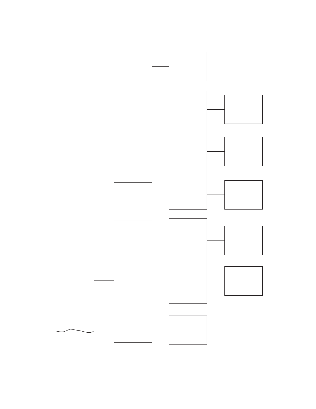
World Class 3000
PROBE DATA DIAGNOSTIC
PROCESS DATA
DATA
O2
Efficiency
Stack Temp
TEMPERATURE
VOLTAGES
Instruction Manual
IB-106-300NH Rev. 4.3
May 2005
Cell
Stack
Cold Junct
Cell
Cell T/C
Stk T/C
Cold Jnt
CALIBRATE O2
(CONTINUED ON
SHEET 2)
PERFORM
CALIBRATION
VIEW
CONSTANTS
CALIBRATION
STATUS
OUTPUT
VALUES
LATEST
CALIBRATION
PREVIOUS CAL
Next Cal
Slope
Constant
Resist
Analog
K1 State
K2 State
Slope
Constant
Resist
Slope
Constant
Resist
686022
Figure 5-2. Quick Reference Chart (Sheet 1 of 5)
Rosemount Analytical Inc. A Division of Emerson Process Management General User Interface (GUI) Operation 5-5
Page 78

Instruction Manual
IB-106-300NH Rev. 4.3
May 2005
World Class 3000
(CONTINUED FROM
SHEET 1)
SETUP
CALIBRATION
O2 CALIBRATION
O2 ALARMS
See sheet 4
SLOPE
CONSTANT
SET POINT
RESET SLOPE
AND CONST
HI ALARM
LO ALARM
ALARM DB
ENABLE CALC
34.5 mV/D-
57.5 mV/D
-20.0 mV-
20.0 mV
o
736 C
o
843 C
0.1000% O2-
25.00% O2
0.00% O2-
25.00% O2
Yes
No
(CONTINUED ON
SHEET 3)
EFFICIENCY
CALC
RELAY OUTPUT
K1 VALUE
K2 VALUE
K3 VALUE
K1 SETUP
K2 SETUP
(CONTINUED ON
SHEET 3)
Figure 5-2. Quick Reference Chart (Sheet 2 of 5)
0.0000-
1.000
0.0000-
20.00
EVENT 1
EVENT 2
EVENT 3
EVENT 1
EVENT 2
EVENT 3
Off
In Cal
Hi O2
Lo O2
Htr Fail
Cal Fail
TG Low
Cell Res
High Range
19860023
5-6 General User Interface (GUI) Operation Rosemount Analytical Inc. A Division of Emerson Process Management
Page 79

World Class 3000
(CONTINUED FROM
SHEET 2)
(CONTINUED FROM
SHEET 2)
ANALOG
OUTPUTS
SOURCE
AOUTTYPE
Instruction Manual
IB-106-300NH Rev. 4.3
May 2005
O2
Efficiency
Dual Rng O2
HART4-20 mA
0-20 mA
0-10 V
SETUP
RANGE SETUP
USA
GBR
COUNTRY
FRA
ESP
GER
Figure 5-2. Quick Reference Chart (Sheet 3 of 5)
See sheet 5
27270004
Rosemount Analytical Inc. A Division of Emerson Process Management General User Interface (GUI) Operation 5-7
Page 80

Instruction Manual
IB-106-300NH Rev. 4.3
May 2005
World Class 3000
CALIBRATION
HIGH GAS
LOW GAS
AUTO CAL
OUTPUT TRACKS
CAL INTRVL
0.1000% O2
25.00% O2
0.1000% O2
25.00% O2
Yes
No
Yes
No
Off,
1H -
365 D OH
(1 hour to 365 days
and no hours)
(CONTINUED FROM
SHEET 2)
Figure 5-2. Quick Reference Chart (Sheet 4 of 5)
NEXT CAL
GAS TIME
PURGE TIME
RES ALARM
Disabled,
1H -
365 D OH
00:30 20:00
00:30 20:00
Ω
50 -
10000
Ω
(1 hour to 365 days
and no hours)
16860025
5-8 General User Interface (GUI) Operation Rosemount Analytical Inc. A Division of Emerson Process Management
Page 81

World Class 3000
Instruction Manual
IB-106-300NH Rev. 4.3
May 2005
Range Setup
(Source not set to:
Dual Rng O2)
(CONTINUED FROM
SHEET 3)
RANGE SETUP
XFER FNCT
RANGE VALUES
XFER FNCT
Log
LIN
HIGH END
LOW END
Log
LIN
0.000% O2
25.00% O2
0.000% O2
25.00% O2
Range Setup
(Source set to:
Dual Rng O2)
HIGH END
NORMAL RANGE
VALUES
DUAL RANGE
SETUP
LOW END
MODE SETUP
HIGH RANGE
VALUES
Figure 5-2. Quick Reference Chart (Sheet 5 of 5)
0.000% O2
25.00% O2
0.000% O2
25.00% O2
RANGE MODE
HIGH IN CAL
SWITCHES AT
LOW END
HIGH END
Normal
Auto
High
Yes
No
0.000% O2
25.00% O2
0.000% O2
25.00% O2
0.000% O2
25.00% O2
16860026
Rosemount Analytical Inc. A Division of Emerson Process Management General User Interface (GUI) Operation 5-9
Page 82

Instruction Manual
IB-106-300NH Rev. 4.3
May 2005
World Class 3000
Table 5-4. CALIBRATE O2 Sub-Menu
SUB-MENU
SELECTION
Perform
Calibration
SETUP SETTING
(SEE TABLE 3-5) DISPLAY DESCRIPTION
Auto Cal in Probe
Setup is YES
Press ENTER to start Auto
Calibration.
MPS will start calibrating probe.
Starting Automatic Calibration
High Gas _____% O
Time Left 0:00
2
Value for high O
Amount of time necessary to com-
calibration gas.
2
plete the current testing phase in
min:sec.
Cell mV ______mV Cell voltage of the probe.
Low Gas _____% O
Time Left 0:00
2
Value for low O
Amount of time necessary to com-
calibration gas.
2
plete the current testing phase in
min:sec.
Cell mV ______mV Cell voltage of the probe.
Resistance Check
Resistance check in progress.
Time Left 0:00
Cell _____mV _____C
Cell voltage and probe temperature.
Calibration Complete
Purging 0:00
Gas lines are being purged of cali-
bration gas.
Cell _____mV _____C
Cell voltage and probe temperature.
Calibration Complete
Auto Cal in Probe
Setup is NO.
Press ENTER to start Manual
Calibration.
Manual calibration sequence will
begin when ENTER is pressed.
Switch ON high calibration gas.
Press ENTER when ready.
High gas ______% O
2
High O2 calibration gas value.
Press ENTER when O2 reading
is stable.
Turn OFF high calibration gas
and ON low calibration gas.
Press ENTER when ready.
Low gas ______% O
2
Low O2 calibration gas value.
Press ENTER when O2 reading
is stable.
Resistance Check. Resistance check in progress.
Turn off low calibration gas.
Press ENTER when ready.
Press ENTER when probe has
returned to process.
5-10 General User Interface (GUI) Operation Rosemount Analytical Inc. A Division of Emerson Process Management
Page 83

World Class 3000
Instruction Manual
IB-106-300NH Rev. 4.3
May 2005
Table 5-4. CALIBRATE O2 Sub-Menu (continued)
SUB-MENU
SELECTION
View
Constants
Calibration
Status
SETUP SETTING
(SEE TABLE 3-5) DISPLAY DESCRIPTION
Latest
Calibration
Previous
Calibration
N/A Next Cal XD XH Time until next calibration in number of
Slope _____mV/D
Constant _____mV
Resist _____ohms
Slope _____mV/D
Constant _____mV
Resist _____ohms
Slope _____
Constant _____
Resist _____
Slope for probe from latest calibration.
Latest calibration offset for probe.
Latest calibration resistance of probe.
Slope for probe from previous calibration.
Previous calibration offset for probe.
Previous calibration resistance of probe.
days and number of hours.
Status of the slope.
Status of the offset.
Status of the resistance.
Rosemount Analytical Inc. A Division of Emerson Process Management General User Interface (GUI) Operation 5-11
Page 84
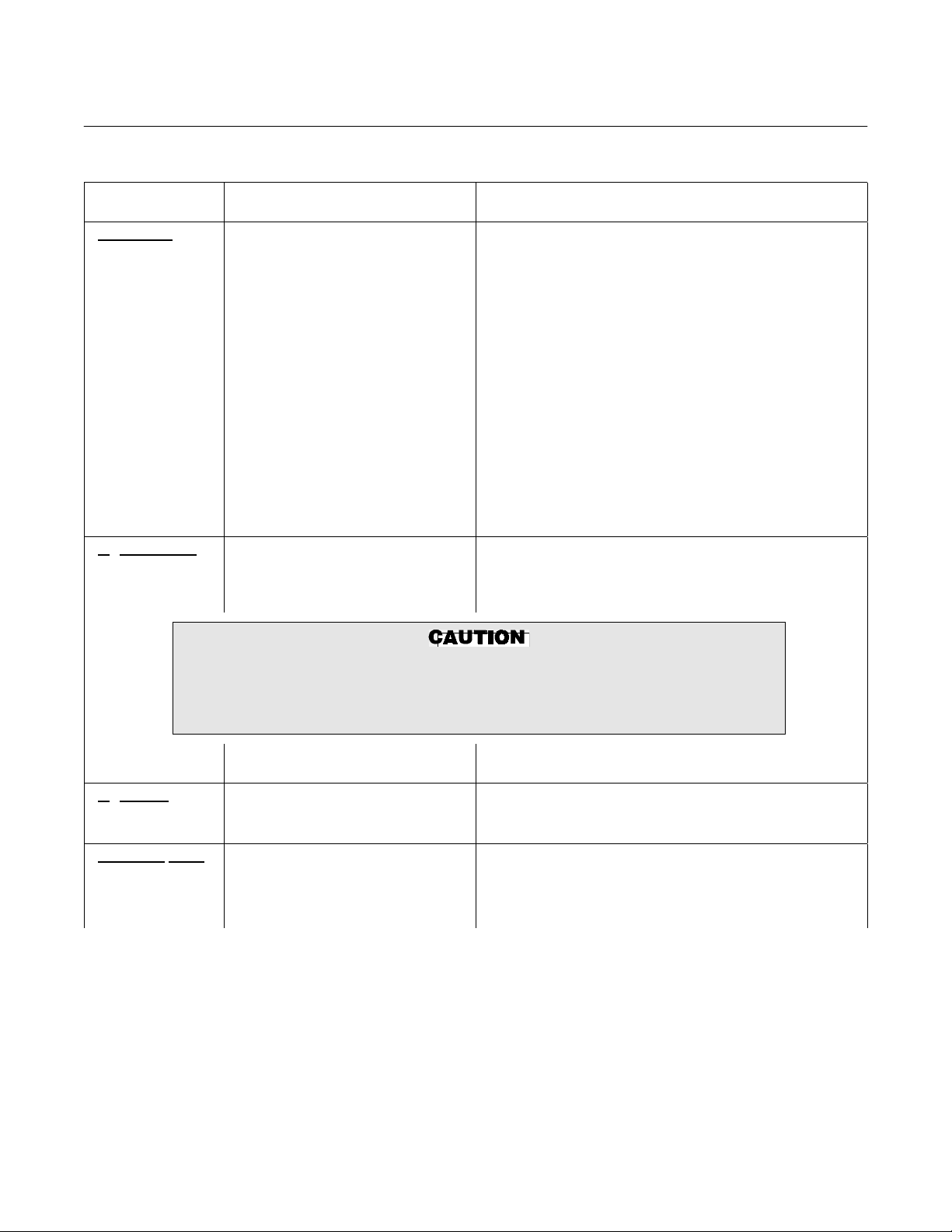
Instruction Manual
IB-106-300NH Rev. 4.3
May 2005
Table 5-5. SETUP Sub-Menu
SUB-MENU
SELECTION PARAMETERS DESCRIPTION
Calibration High Gas ____% O
Low Gas ____% O
2
2
Value of high O2 calibration gas (0.1000% - 25.00%
O
).
2
Value of low O2 calibration gas (0.1000% - 25.00%
O
).
2
Auto Cal YES/NO MPS required for Auto Cal.
Output Tracks YES/NO NO, locks output during calibration.
Cal Intrvl XD XH Select time between calibrations in number of days
and hours (1 year max).
Next Cal XH Time until next calibration in number of hours
(1 year max).
Gas Time 0:30 - 20:00
Amount of time calibration gases will be turned on in
number of minutes and seconds; allow enough time
for signal values to stabilize.
Purge Time 0:30 - 20:00 Amount of time for gas lines to clear of calibration
gas.
Res Alarm 50 W – 10 kW Resistance alarm set from 50 to 10,000 ohms.
O2 Calculation Slope ____ mV/D
Constant ____ mV
Set Point ____°C
Set value between 34.5 and 57.5.
Set value between -20.0 and +20.0 mV.
Set either 736 for World Class 3000 probes or 843
for 218 probes.
World Class 3000
Ensure the correct voltage is selected when using HPS 3000 with either World
Class 3000 probes or 218 probes. Refer to Figure 2-13, Jumper Selection Label
for proper voltage selections. If incorrect SET POINT is selected, damage to
the probe may occur.
Reset slope and constants. Press ENTER to reset slope and constants to values
O2 Alarms Hi Alarm ____% O
Lo Alarm ____% O
Alarm DB ____% O
Efficiency Calc. Enable Calc. YES/NO
K1 Value _______
K2 Value _______
K3 Value _______
from the latest successful calibration.
2
2
2
Set value for high alarm limit (0.1000% - 25.00%).
Set value for low alarm limit (0.1000% - 25.00%).
Set value for alarm dead band (0.0000% - 25.00%).
Select YES to enable, NO to disable.
Set between 0.0000 and 1.000. Refer to Table 5-6.
Set between 0.0000 and 1.000. Refer to Table 5-6.
Set between 1.000 and 20.00. Refer to Table 5-6.
5-12 General User Interface (GUI) Operation Rosemount Analytical Inc. A Division of Emerson Process Management
Page 85

World Class 3000
Table 5-5. SETUP Sub-Menu (continued)
SUB-MENU
SELECTION PARAMETERS DESCRIPTION
Relay
Outputs
NOTE
K1 and K2 relay outputs can be configured for "OFF" or any one of the eight
events listed below. Up to three events can control each relay output. Ev ents are
selected in the SETUP sub-menu.
K1 Setup
K2 Setup
Analog
Output
Event 1 1. In Cal
Event 2 2. Hi O
Event 3 3. Lo O
Event 1 4. Htr Fail
Event 2 5. Cal Fail
Event 3 6. TG Low
SOURCE O
-Off
2
2
7. Cell Res
8. High Range
2
Efficiency
Dual Rng O
2
No effect.
Probe goes into calibration status.
Output exceeds high end alarm limit.
Output goes below low alarm limit.
Probe heater fault occurs.
Probe failed last calibration.
Calibration gas pressure gets too low.
Probe resistance exceeds high limit.
High analog output range is selected.
Select the measurement value to be represented on
the analog output.
Instruction Manual
IB-106-300NH Rev. 4.3
May 2005
AOUT TYPE
HART 4-20mA
0-20mA
0-10V
RANGE SETUP
(Source not set to Dual Rng O2)
Xfer Fnct Log
Lin
Range Values
High End
0.000% O
- 25.00% O
2
Low End
0.000% O
- 25.00% O
2
Select one of the listed options to define upper and
lower limits of probe analog output. Only a selection
that matches the position of the analog output selector
switch on the microprocessor board (Figure 2-8) will
be accepted. The defined limits correspond to the
upper-lower %O
values defined in the Range Setup
2
menu.
Select the transfer function used on the analog output.
Selecting Log will not effect the output when Efficiency
is selected as the Source.
Enter the upper and lower analog output range values.
The High End value defines the measured O
2
corresponding to the high analog output value, i.e.,
20mA or 10V, and the Low End value corresponds to
2
the low analog output value, i.e., 0mA, 4mA, or 0V.
value
2
Rosemount Analytical Inc. A Division of Emerson Process Management General User Interface (GUI) Operation 5-13
Page 86

Instruction Manual
IB-106-300NH Rev. 4.3
May 2005
Table 5-5. SETUP Sub-Menu (continued)
SUB-MENU
SELECTION PARAMETERS DESCRIPTION
Analog Output RANGE SETUP
(continued) (Source set to Dual Rng O2)
Xfer Fnct Log
Lin
Select the transfer function used on the analog output.
Selecting Log will not effect the output when Efficiency
is selected as the Source.
World Class 3000
Normal Range Values
High End
0.000% O
- 25.00% O
2
Low End
0.000% O
- 25.00% O
2
Enter the upper and lower analog output range values
for Normal Operating Range. The High End value defines the measured O
2
analog output value, i.e, 20mA or 10V, and the Low
End value corresponds to the low analog output value,
2
i.e., 0mA, 4mA, or 0V.
value corresponding to the high
2
Dual Range Setup
Mode Setup
Range Mode Normal Forces the output to the Normal Range.
Auto Allows the IFT to select either the High Range or the
Normal Range based on the present O
value and the
2
Mode Setup Values.
High Forces the output to the High Range.
High in Cal Yes/No Selecting Yes will cause the High Range to be used
whenever the probe is being calibrated.
Switches at
0.000% O
- 25.00% O
2
2
Enters the switching point between the High and Normal Ranges. O
values above this point will use the
2
High Range and values below this point will use the
Normal Range. The O
value must be below the switch
2
point by 10% (of the "Switches at" value) to cause a
switch from High to Normal Range.
High Range Values
High End
0.000% O
- 25.00% O
2
Low End
0.000% O
- 25.00% O
2
2
2
Enter the upper and lower analog output range values
for High Operating Range. The High End value defines
the measured O
value corresponding to the high
2
analog output value, i.e., 20mA or 10V, and the Low
End value corresponds to the low analog output value,
i.e., 0mA, 4mA, or 0V.
NOTE: Relay output can be initiated upon range change. (See page 5-12 of Table 5-5.)
Table 5-6. Efficiency Constants
UNITED STATES EUROPE
CONSTANT
GAS OIL GAS OIL
K1 0.407 0.432 0.66 0.69
K2 0.0 0.0 0.0082 0.0051
K3 5.12 5.12 12.28 8.74
5-14 General User Interface (GUI) Operation Rosemount Analytical Inc. A Division of Emerson Process Management
Page 87

World Class 3000
Instruction Manual
IB-106-300NH Rev. 4.3
May 2005
SECTION 6
TROUBLESHOOTING
6-1 OVERVIEW
The system troubleshooting describes how to
identify and isolate faults which may develop in
the Oxygen Analyzer System. Refer to Probe,
IFT, HPS, MPS, and HART Communicator
appendices.
Install all protective equipment covers
and safety ground leads after troubleshooting. Failure to replace covers
and ground leads could result in serious injury or death.
6-2 SPECIAL TROUBLESHOOTING NOTES
a. Grounding
It is essential that adequate grounding precautions are taken when the system is being installed. A very thorough check must
be made at both the probe and electronics
to ensure that the grounding quality has not
degraded during fault finding. The system
provides facilities for 100% effective
grounding and the total elimination of
ground loops.
b. Electrical Noise
The IFT has been designed to operate in
the type of environment normally found in a
boiler room or control room. Noise suppres-
sion circuits are employed on all field terminations and main inputs. When fault finding,
the electrical noise being generated in the
immediate circuitry of a faulty system should
be evaluated. All cable shields must be
connected to earth.
c. Loose Integrated Circuits
The IFT uses a microprocessor and supporting integrated circuits. Should the electronics unit receive rough handling during
installation in a location where it is subjected to severe vibration, an Integrated
Circuit (IC) could work loose. The fault finding guides in paragraph 6-3 and Table E-2
in Appendix E, show the resulting variety of
failure modes. It is recommended that all
IC's be confirmed to be fully seated before
troubleshooting on the system begins.
d. Electrostatic Discharge
Electrostatic discharge can damage the IC's
used in the electronics unit. It is essential
that the user ensure he/she is at ground
potential before removing or handling the
processor board or the IC's used on it.
6-3 SYSTEM TROUBLESHOOTING
The status line of the GUI equipped IFT will display one of ten conditions. The system status
displays will be displayed one at a time in priority sequence, as indicated in Table 6-1.
Rosemount Analytical Inc. A Division of Emerson Process Management Troubleshooting 6-1
Page 88

Instruction Manual
IB-106-300NH Rev. 4.3
May 2005
World Class 3000
Table 6-1. IFT Status Codes
Off Heater power has been turned OFF by the electronics. The display shows 0% O
. Several con-
2
ditions may cause the OFF status:
1. The cell heater temperature is below -50°C. The thermocouple wires may be reversed.
2. The cell temperature is more than 70°C above the set point. The heater is out of control.
The triac module may have failed.
3. The cell heater thermocouple voltage has remained within +1.5 mV for more that 4 minutes.
The thermocouple may be shorted.
4. The AD590 voltage is below 50.0 mV (50K or -223°C). The AD590 is not connected.
5. The AD590 voltage is above 363 mV (363K or 90°C). If HPS is used with IFT, then IFT interconnect board has JM1 in position connecting two AD590s in parallel.
PrbEr The probe is disconnected or cold, or leads are reversed.
HtrEr There is a fault within the heater system. The heater temperature is more than +25°C from the
set point. When the unit is first turned ON, HtrEr is normal. The heater may take 0.5 to 1.0
hours to warm up.
InCal The system is currently undergoing calibration. If Output Tracks is set to YES, the output will
show changing O
values. If Output Tracks is set to NO, the output will hold the pre-calibration
2
value.
LowO
2
The measured O2 value is below the low O2 alarm limit. The problem may be in the probe or the
process.
HiO
2
The measured O2 value is above the high O2 alarm limit. The problem may be in the probe or
the process.
NoGas Test gas pressure is too low. Pressure switches are set to trigger this alarm at 12 to 16 psig (83
to 110 kPa gage). Test gas regulators are usually set at 20 to 25 psig (138 to 172 kPa gage).
Possible causes are:
1. At least one test gas pressure switch is open.
2. A test gas cylinder is empty.
3. There is an MPS or piping failure.
4. If MPS is not connected, CALRET and NOGAS signals should be jumpered on the interconnect board.
CalEr An error occurred during the last calibration. The error may be one of the following:
1. The new calculated slope value is outside the range 34.5 to 57.6 mV/decade.
2. The new calculated constant value is outside the range +20.0 to -20.0 mV.
3. The test gas pressure switch opened during calibration.
Ensure that the proper test gases are being used, and that the gas flows are set properly. Refer
to Appendix D for additional MPS troubleshooting information.
ResHi The resistance calculated during the last good calibration was greater than the High Resistance
Alarm limit set in the calibration setup. The resistance limit may be set wrong, or there is a
problem with the probe.
Ok Operation appears to be normal.
(blank
screen)
6-2 Troubleshooting Rosemount Analytical Inc. A Division of Emerson Process Management
A possible failure within the IFT. Check the LED on the microprocessor board to help isolate
problems. See IFT Problem in the troubleshooting tables.
Page 89

World Class 3000
Instruction Manual
IB-106-300NH Rev. 4.3
May 2005
6-4 HEATER PROBLEM
For all heater troubleshooting, allow at least 30
minutes for the operating temperature to stabilize. After the warmup period, observe the system status and the voltages of the cell TC and
the cold junction AD590. For heater related
problems:
a. The status line may read: HtrEr or OFF.
Table 6-2. Heater Troubleshooting
Problem
Cause
Corrective Action
Status is HtrEr or OFF.
Cell TC < 28.4 mV.
Cold Junction 273 to 330 mV (normal).
O
Display = 0%
2
1. Blown fuse or faulty wiring.
Check all fuses and wiring for continuity and repair as needed. Verify that input power
jumpers are installed correctly. Check jumpers for proper configuration in IFT and HPS if used.
2. Heater failure.
In HPS with power OFF, check heater resistance at J2, terminals R/H. For 44 V heater, resistance should be 11 to 14 ohms. For 115 V heater, resistance should be 67 to 77 ohms. Check
wiring, and replace heater if needed. Heater resistance can also be checked at the probe junction box:
• 44 V heater: terminals 7 and 8 should measure 11 to 14 ohms.
• 115 V heater: terminals 5 and 6 should measure 67 to 77 ohms. (Terminals 6 to 7 and 6 to
8 should be open circuits.)
3. Triac open.
Check the triac. Repair as needed.
4. Electronics failure.
First check and repair all related wiring. Check and repair electronics as needed.
5. Missing insulation around heater.
Check that insulation is in place and undamaged. Repair or replace insulation as needed.
b. The displayed O
c. Cell TC voltages will vary from normal.
These voltages are found by accessing the
proper menu. In the IFT, use the DIAGNOSTIC DATA sub-menu of the PROBE
DATA menu.
Refer to Table 6-2 to troubleshoot heater related
problems.
value will read 0%.
2
Rosemount Analytical Inc. A Division of Emerson Process Management Troubleshooting 6-3
Page 90

Instruction Manual
IB-106-300NH Rev. 4.3
May 2005
Table 6-2. Heater Troubleshooting (continued)
Problem
Cause
Corrective Action
Status is HtrEr or OFF.
Cell TC > 28.4 mV.
Cold Junction 273 to 330 mV (normal).
O
Display = 0%
2
1. Triac failure.
Check the triac. Repair as needed.
2. Wrong TC set point.
Check electronics manual and verify the set point; typically 1356°F (736°C).
3. Wrong heater voltage selected. HPS voltage jumpers setup wrong.
For 44 V heater, make sure JM7 is installed and JM8 is removed. For 115 V heater, JM7 is
removed and JM8 is installed. The 115 V heater has an identifying stainless steel tag attached
in the junction box.
Status is HtrEr or OFF.
Cell TC < 28.4 mV.
Cold Junction < 273 mV.
O
Display = 0%
2
1. Wiring error, thermocouple wires reversed.
Verify TC wiring at junction box terminal and electronics. The yellow chromel line connects to
terminal 3. The red alumel line connects to terminal 4. Trace line through the HPS (if used)
and the electronics. Reverse wires if needed.
2. Faulty thermocouple. At a cold junction reference of 77°F (25°C), the probe TC should read about
29.3 mV.
Replace faulty thermocouple.
3. Faulty AD590. At normal ambient temperatures, cold junction sensor should be 273 to 330 mV.
Replace faulty sensor.
World Class 3000
Status is HtrEr or OFF.
Cell TC = -40 mV.
Cold Junction 273 to 330 mV (normal).
O
Display = 0%
2
1. Faulty thermocouple connection or open.
Verify TC wiring at junction box terminal and electronics. The yellow chromel line connects to
terminal 3. The red alumel line connects to terminal 4. Trace line through the HPS (if used)
and the electronics. Repair connection or wiring as needed.
2. Thermocouple fault. At a cold junction reference of 77°F (25°C), the probe TC should read a bout
29.3 mV.
Replace faulty thermocouple.
6-4 Troubleshooting Rosemount Analytical Inc. A Division of Emerson Process Management
Page 91

World Class 3000
Instruction Manual
IB-106-300NH Rev. 4.3
May 2005
6-5 CELL PROBLEM
For cell troubleshooting, as in heater problems,
you should allow at least 30 minutes for operating temperature to stabilize. After this warmup
period, observe the system status and cell voltage. If the heater is working, troubleshoot the
cell. If the heater is not working, refer to Heater
Problem, paragraph 6-4.
• The status line may read: Low O
CalEr, ResHi.
• Access voltage values in the proper menu.
Use the DIAGNOSTIC DATA sub-menu of
the PROBE DATA menu.
Problem
Cause
Corrective Action
Status is LowO2.
Cell mV = -127 mV.
1. Faulty cell connection or open. If the cell circuit is open, the cell output will show about -127 mV.
Check cable connection between the probe and the electronics. Check that the probe spring
presses the contact pad firmly onto the cell. Repair or replace faulty wires, spring, or connectors.
2. Electronics fault. Cell output is good, and the input to the electronics is good.
Check the electronics package. Replace the microprocessor or interfa ce boa rd as needed.
• The displayed O
99%.
• It may be helpful to observe the calibration
status and parameters from the last calibration: Slope, Constant, and Cell Resistance.
In the CALIBRATE menu, VIEW CONSTANTS shows previous calibration values,
and CALIBRATION STATUS shows the
, Hi O2,
2
Table 6-3. Cell Troubleshooting
latest values. If these values appear out of
range, perform a calibration before troubleshooting the cell.
Refer to Table 6-3 to troubleshoot cell related
problems.
value will read 0% to
2
Status is ResHi or CalEr.
Cell mV = -20 to 120 mV (normal).
1. Test gas flow not 5 scfh (2.4 L/min).
Check test gas flow and related piping. Rotameter should show 5 scfh. Adjust needle valve for
correct flow rate.
2. Incorrect test gas.
Confirm labels on test gas bottles are correct. Confirm High Gas and Low Gas values agree with
labels on test gas bottles. (Refer to menu map — SETUP-CALIBRATION, High Gas, Low Gas.)
Check all ports, cylinders, and gas lines for proper hookup. Change piping if nece ssary. Label
pipes for reference.
Rosemount Analytical Inc. A Division of Emerson Process Management Troubleshooting 6-5
Page 92

Instruction Manual
IB-106-300NH Rev. 4.3
May 2005
Table 6-3. Cell Troubleshooting (continued)
Problem
Cause
Corrective Action
Status is ResHi or CalEr.
Cell mV = -20 to 120 mV (normal) (continued).
1. Reference air contamination (oil/water).
Clean or replace lines and valves as needed.
2. Cell leads reversed.
Check cell signal wiring from probe junction box to electronics, and correct wiring if needed.
3. Reference/test gas lines reversed.
Switch piping as needed.
4. Diffusion element fault. Diffusion element cracked, broken, missing, or plugged.
Replace diffusor or snubber as needed. Diffusors are disposable because it is difficult to clean a
diffusor and know the tiny pores are open. A flow and pressure test with a manometer is possible but usually not practical. To clean a snubber, blow off surface dirt with pressurized air and
clean the unit in an ultrasonic bath.
5. Faulty cell. Low sensor cell output when test gas is applied.
If test gas flow is good and there is low cell signal, replace the cell, or call the SCAN line for
assistance.
World Class 3000
Typical cell output:
Test Gas mV
8.0% 18 to 25
0.4% 76 to 86
6. Cell performance degraded from aging.
Replace the sensor cell if its resistance has increased beyond 1 kOhm and the sl ope calculated
during calibration has decreased lower than 40 mV/decade.
7. Electronics fault. Cell output is good, and the input to the electronics is good.
Check the electronics package. Replace the microprocessor or interfa ce boa rd as needed.
Status is Res Hi.
Cell mV = -120 to 20 mV.
1. Cell leads reversed.
Check cell signal wiring from probe junction box to electronics, and correct wiring if neede d.
2. Reference/test gas lines reversed.
Switch piping as needed.
3. Reference air (nitrogen).
Confirm labels on test gas bottles are correct. 100% nitrogen must NOT be used as a zero gas
because cell protection will engage and affect the O
instrument air prepared from ambient air with 20.95% O
reading. Reference air should be clean, dry
2
.
2
6-6 Troubleshooting Rosemount Analytical Inc. A Division of Emerson Process Management
Page 93

World Class 3000
Instruction Manual
IB-106-300NH Rev. 4.3
May 2005
6-6 IFT PROBLEM
When an IFT problem is suspected, look at the
LED on the microprocessor board. The LED
may be OFF, ON, or flashing.
Table 6-4. IFT Troubleshooting
Problem
Cause
Corrective Action
IFT LED is OFF. IFT failure.
Fuse fault.
Check fuses on power supply board. Replace fuses as needed.
1. Power fault.
Check line voltage. Correct or turn main power ON.
2. Power supply fault.
Check voltage test points on the microprocessor board. Replace power supply board if nee ded.
3. Microprocessor board fault.
Replace microprocessor board.
IFT LED is steady ON. Heater or cell wiring problem.
1. Faulty wiring.
Check thermocouple and heater wires and connections for continuity. Repair as needed.
2. Jumpers set up wrong. JM1 on interconnect board, JM6 on microprocessor board, or JM9 and JM10
on power supply board are configured incorrectly.
Check that jumpers are set up as follows:
• Without an HPS, JM1 and JM6 should be installed.
• With a 115 V probe heater, JM9 is installed.
• With a 44 V probe heater, JM10 is installed.
3. Status line is “OFF”.
Turn OFF IFT power and restart. If light stays ON and both wiring and jumpers are OK, then replace the microprocessor board.
Refer to Table 6-4 to troubleshoot IFT related
problems.
Faulty GUI or LDP (IFT LED is Flashing).
1. Microprocessor is normal, but front panel indicators are not working properly.
Check connections to GUI or LDP, and repair or replace as needed.
Rosemount Analytical Inc. A Division of Emerson Process Management Troubleshooting 6-7
Page 94

Instruction Manual
IB-106-300NH Rev. 4.3
May 2005
World Class 3000
6-7 MPS PROBLEM
MPS problems can occur with a status of C Err,
R Hi, TGLow. The O
Problem
Cause
Corrective Action
Status is NoGas.
Cell mV is between -20 to 120 mV.
1. Regulator or plumbing fault. The test gas pressure is low for the indicated probe [20 to 25 psig (138 to
172 kPa gage)].
Check test gas pressure [should be 20 psig (138 kPa gage)], regul ator, and lines. Reset, repair,
or replace the regulator as needed. If only one probe has low flow [less than 5 scfh (2.4 L/min)],
check lines, needle valve, connectors, and MPS solenoid for that probe.
2. Test gas low.
Replace empty test gas cylinder with full cylinder. Verify O
3. Wiring fault.
Confirm proper wiring and continuity between MPS and electronics. Repair as needed.
4. Pressure switch fault.
Pressure switch is factory set at 16 psig (68.9 kPa gage). Set test gas regulator pressure to 20
psig (138 kPa gage) to avoid nuisance alarms. Replace faulty switch with a new one if test gas
supply is good.
reading can be 0% to
2
99%, and probe data will be in the normal
ranges. Consider two conditions, A and B.
Refer to Table 6-5 to troubleshoot problems with
the MPS.
Table 6-5. MPS Troubleshooting
concentration.
2
Status is ResHi or CalEr.
Cell mV is between -20 to 120 mV.
The CalEr occurs when the slope calculated from the last calibration was out of range. CalEr can b e
caused by leaks, a faulty diffusor or sensor cell, erroneous test gas values, or not enough test gas time.
Each test gas should be supplied for at least three minutes.
1. Flowmeter set incorrectly.
The flowmeter for each probe must be set individually. Flow should be 5 scfh (2.4 L/min).
2. Wiring fault.
Confirm proper wiring and continuity between MPS and electronics.
3. Piping fault. Faulty gas line or regulator.
Check gas line, valves, and regulators for blockage or corrosion. Repair or replace as ne eded.
4. Solenoid fault.
Verify nominal 24 VDC at HI GAS, LOW GAS, IN CAL, and CAL RET connections. Voltages
should drop to about 4 VDC. If voltage is present but solenoid does not work, replace the
solenoid.
5. Termination board fault.
Verify 24 VDC at J11 on termination board. Repair or replace termination board or connectors as
needed.
6. Power supply fault.
Verify power supply fuses and output are good and that line voltage is present at J1. Repair or
replace the power supply as needed.
7. Power fault.
Check fuses, mains, and circuit breakers. Repair or replace as needed.
6-8 Troubleshooting Rosemount Analytical Inc. A Division of Emerson Process Management
Page 95

World Class 3000
Instruction Manual
IB-106-300NH Rev. 4.3
May 2005
6-8 PERFORMANCE PROBLEM (PROCESS
RESPONSE IS SUSPECT)
readings may not always agree with known
O
2
process conditions. Such a discrepancy can be
the first sign of a problem either in the process
or the World Class 3000. The O
display will
2
Table 6-6. Performance Problem Troubleshooting
Problem
Cause
Corrective Action
Status is OK.
Cell mV is -20 to 120 mV (normal).
O
display is stable but not expected value.
2
Such a condition occurs during various kinds of leaks and data output faults.
1. Mounting flange leak.
Reseal the flange, and tighten bolts properly.
2. Test gas line leak.
Since the test gas line is under positive pressure, the line can be tested with a bubbling liquid
such as SNOOP
TM
. Repair or replace as needed.
3. Silicon hose break. Leaks may occur in the silicon rubber hose in the probe junction box.
Replace hose.
4. Air ingress from leaky duct.
Check condition of duct, gas lines, and fittings. If duct has air ingress upstream of probe, re-site
the probe or fix the leak.
5. Analog output or recorder fault.
Measure analog output in voltage or milliamps as set up on the analog output board and software. If analog output is not in range, replace the microprocessor board in the IFT. Check recorder function, and repair as needed.
6. Random spiking of the analog output to 0 mA dc.
Check the power supply voltage. If suspect, replace the power supply board in the IFT.
read between 0 to 99%, but the reading may be
unstable. The status line may read OK, and
PROBE DATA voltages may read normal.
Refer to Table 6-6 to troubleshoot performance
problems.
Status is OK.
Cell mV is -20 to 120 mV (normal).
O
display is unstable.
2
1. Process variations.
Analyze the process for even flows of gases or materials. Check the operation of dampers and
control valves. Repair process devices, procedures, and flows as needed. Depending on the
process, some variation may be normal.
2. Pad to cell connection fault.
Check pad and contact for cleanliness, and clean as needed. Check spring tension, and replace
as needed.
3. Grounding fault.
Check all wiring for continuity and connections for cleanliness and lack of corrosi on. Repair as
needed.
4. Improper line voltage.
Check line voltage circuit for proper polarity and/or "hot" and "neutral" circuitry.
Rosemount Analytical Inc. A Division of Emerson Process Management Troubleshooting 6-9
Page 96

Instruction Manual
IB-106-300NH Rev. 4.3
May 2005
World Class 3000
6-10 Troubleshooting Rosemount Analytical Inc. A Division of Emerson Process Management
Page 97

World Class 3000
Instruction Manual
IB-106-300NH Rev. 4.3
May 2005
SECTION 7
RETURN OF MATERIAL
7-1 If factory repair of equipment is required, pro-
ceed as follows:
a. Secure a return authorization number from
a Rosemount Analytical Sales Office or representative before returning the equipment.
Equipment must be returned with complete
identification in accordance with Rosemount
Analytical instructions or it will not be accepted.
In no event will Rosemount Analytical be
responsible for equipment returned without
proper authorization and identification.
b. Carefully pack faulty unit in a sturdy box
with sufficient shock absorbing material to
insure that no additional damage will occur
during shipping.
c. In a cover letter, describe completely:
1. The symptoms from which it was determined that the equipment is faulty.
2. The environment in which the equipment has been operating (housing,
weather, vibration, dust, etc.).
3. Site from which equipment was
removed.
5. Complete shipping instructions for return of equipment.
6. Reference the return authorization
number.
d. Enclose a cover letter and purchase order
and ship the equipment according to the
instructions provided in the Rosemount
Analytical Return Authorization, prepaid, to:
PAD Repair Depot Dock C
c/o Emerson Process Management
11100 Brittmoore Park Drive
Houston, TX 77041
If warranty service is requested, the faulty
unit will be carefully inspected and tested at
the factory. If failure was due to conditions
listed in the standard Rosemount Analytical
warranty, the faulty unit will be repaired or
replaced at Rosemount Analytical's option,
and an operating unit will be returned to the
customer in accordance with shipping instructions furnished in the cover letter.
For equipment no longer under warranty,
the equipment will be repaired at the factory
and returned as directed by the purchase
order and shipping instructions.
4. Whether warranty or nonwarranty
service is requested.
Rosemount Analytical Inc. A Division of Emerson Process Management Return of Material 7-1
Page 98

Instruction Manual
IB-106-300NH Rev. 4.3
May 2005
World Class 3000
7-2 Return of Material Rosemount Analytical Inc. A Division of Emerson Process Management
Page 99

Instruction Manual
IB-106-300NH Rev. 4.3
World Class 3000
SECTION 8
APPENDICES
APPENDIX A. WORLD CLASS 3000 OXYGEN ANALYZER (PROBE)
APPENDIX B. HPS 3000 HEATER POWER SUPPLY
APPENDIX D. MPS 3000 MULTIPROBE CALIBRATION GAS SEQUENCER
APPENDIX E. IFT 3000 INTELLIGENT FIELD TRANSMITTER
APPENDIX J. HART COMMUNICATOR MODEL 375D9E IFT 3000 APPLICATIONS
May 2005
Rosemount Analytical Inc. A Division of Emerson Process Management Appendices 8-1
Page 100

Instruction Bulletin
Appendix A Rev. 3.9
May 2005
NOTE: NOT ALL PARTS SHOWN ARE AVAILABLE FOR
PURCHASE SEPARATELY. FOR LIST OF
AVAILABLE PARTS, SEE TABLE A-3.
1
APPENDIX A
26
20
World Class 3000
1. Heater, Strut, and Backplate Assembly
2. Diffusion Assembly
3. Retainer Screw
4. Cell and Flange
5. Corrugated Seal
6. Probe Tube Assembl y
7. Screw
8. Washer
9. Cover Chain Screw
10. Cover Chain
11. Probe Junction Box Cover
12. Cover Gasket
13. Wiring Diagram
14. O-Ring
15. Terminal Block Screws
16. Terminal Block
17. Terminal Block Marker
18. Terminal Block Mounting Plate
3
2
4
19. Probe Junction Box Screws
20. Hose Clamp
21. Hose
22. Gas Connection
23. Seal Cap
24. Label
25. Probe Junction Box
26. Ground Wires
27. Insulating Gasket
28. Washer
29. Screw
18
23
21
19
16
14
20
12
29
10
17
11
13
15
8
7
9
21240005
28
27
25
24
11
22
10
5
6
NOTE: ITEM , CALIBRATION GAS TUBE,
FITS INTO HOLES WHEN PROBE IS
ASSEMBLED.
Figure A-1. Oxygen Analyzer (Probe) Exploded View
A-0 Appendices Rosemount Analytical Inc. A Division of Emerson Process Management
 Loading...