

Page 1
00825-0100-2460, Rev AA
Rosemount™ 2460 System Hub
Quick Start Guide
September 2020
Page 2

Quick Start Guide September 2020
Contents
About this guide...........................................................................................................................3
Overview......................................................................................................................................5
General information...................................................................................................................11
Installation................................................................................................................................. 12
Configuration.............................................................................................................................35
Operation...................................................................................................................................58
Product certifications................................................................................................................. 59
2 Rosemount 2460 Tank Hub
Page 3
September 2020 Quick Start Guide
1 About this guide
This Quick Start Guide provides basic guidelines for installation and
configuration of the Rosemount 2460 System Hub.
NOTICE
Read this manual before working with the product. For personal and system
safety, and for optimum product performance, ensure you thoroughly
understand the contents before installing, using, or maintaining this
product.
For equipment service or support needs, contact your local Emerson
Automation Solutions/Rosemount Tank Gauging representative.
Spare Parts
Any substitution of non-recognized spare parts may jeopardize safety.
Repair, e.g. substitution of components etc, may also jeopardize safety and
is under no circumstances allowed.
Rosemount Tank Radar AB will not take any responsibility for faults,
accidents, etc caused by non-recognized spare parts or any repair which is
not made by Rosemount Tank Radar AB.
CAUTION
Make sure that there is no water or snow on top of the lid when it is opened.
This may damage the electronics inside the housing.
CAUTION
Be careful when opening the lid in very low temperatures. High humidity and
temperatures far below the freezing point may cause the gasket to get stuck
to the lid. In that case you may use a heating fan to warm the housing in
order to release the gasket. Be careful not to use excess heat which may
damage the housing and electronics.
CAUTION
The products described in this document are NOT designed for nuclearqualified applications. Using non-nuclear qualified products in applications
that require nuclear-qualified hardware or products may cause inaccurate
readings. For information on Rosemount nuclear-qualified products, contact
your local Emerson Sales Representative.
Quick Start Guide 3
Page 4

Quick Start Guide September 2020
WARNING
Failure to follow safe installation and servicing guidelines could result in
death or serious injury.
• Ensure only qualified personnel perform the installation.
• Use the equipment only as specified in this manual. Failure to do so may
impair the protection provided by the equipment.
• Do not perform any service other than those contained in this manual
unless you are qualified.
• Substitution of components may impair Intrinsic Safety.
Explosions could result in death or serious injury.
• Verify that the operating atmosphere of the transmitter is consistent
with the appropriate hazardous locations certifications.
• Do not remove the gauge cover in explosive atmospheres when the
circuit is alive.
High voltage that may be present on leads could cause electrical shock.
• Avoid contact with the leads and terminals.
• Ensure the mains power to the device is off and the lines to any other
external power source are disconnected or not powered while wiring the
device.
Electrical shock could cause death or serious injury.
• Use extreme caution when making contact with the leads and terminals.
WARNING
Physical access
Unauthorized personnel may potentially cause significant damage to and/or
misconfiguration of end users’ equipment. This could be intentional or
unintentional and needs to be protected against.
Physical security is an important part of any security program and
fundamental to protecting your system. Restrict physical access by
unauthorized personnel to protect end users’ assets. This is true for all
systems used within the facility.
4 Rosemount 2460 Tank Hub
Page 5
A I
F
J J
K
L
M
O
G
C
E
H
N
DBE
September 2020 Quick Start Guide
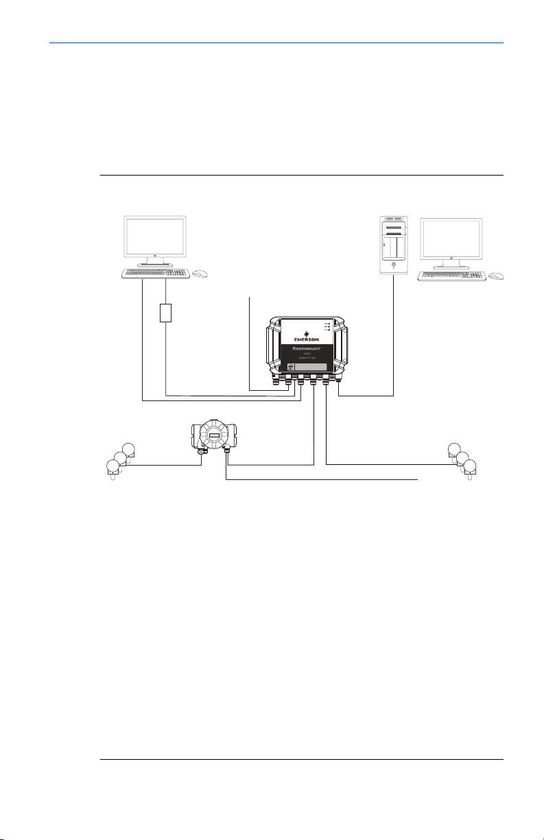
2 Overview
2.1 Communication
The Rosemount Tank Gauging system supports various communication
interfaces for field devices, TankMaster PC and other host computers.
Figure 2-1: Typical Configuration of a Rosemount 2460 System Hub
A. TankMaster
B. USB, RS232
C. Modem
D. Ethernet (Modbus TCP), RS232, RS485
E. TRL2, RS485
F. DCS/Other hosts (TRL2, RS485, RS232)
G. Rosemount 2460 System Hub
H. Modbus RTU/TCP
I. Other hosts
J. Field devices
K. Tankbus
L. Rosemount 2410 Tank Hub
M. Primary bus: TRL2, RS485
N. TRL2, RS485, other vendors
O. Secondary bus: Enraf, Whessoe and others, HART 4-20 mA analog
output/input
Quick Start Guide 5
Page 6

Quick Start Guide September 2020
The Rosemount 2460 System Hub collects measurement data from field
devices and transmits the data to a host system. It also handles
communication from a host to the field devices.
The Rosemount 2460 supports a number of host communication interface
standards such as Ethernet, TRL2, RS485, and RS232. TRL2 and RS485 are
supported for field device communication also, as well as other standards
such as Enraf and Digital Current Loop (Whessoe).
6 Rosemount 2460 Tank Hub
Page 7
A
B
C
E
F
G
D
September 2020 Quick Start Guide
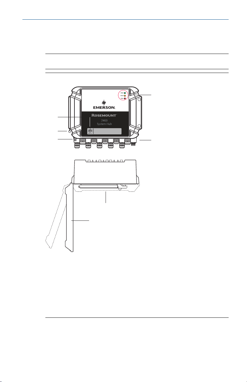
2.2 Components
This section shows the various parts of the Rosemount 2460 System Hub.
Note
The Rosemount 2460 is designed for use in non-hazardous areas.
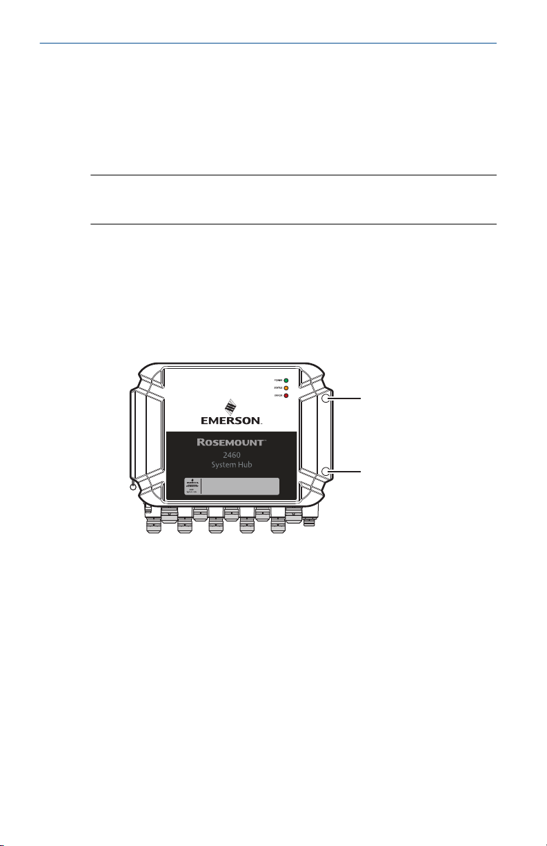
Figure 2-2: Rosemount 2460 System Hub Front and Top View
A. Main label
B. Locking ring for securing lid
C. External ground terminal (M5 screw, flat, lug dimension max. 10 x 4
mm)
D. LEDs for status and error messages
E. Cable entries (Nine (9) M20 x 1.5, Two (2) M25 x 1.5)
F. Lid (can be removed by removing the locking ring)
G. Terminal compartment with communication boards and ports
Quick Start Guide 7
Page 8
A
D
E F G
C
B
Quick Start Guide September 2020
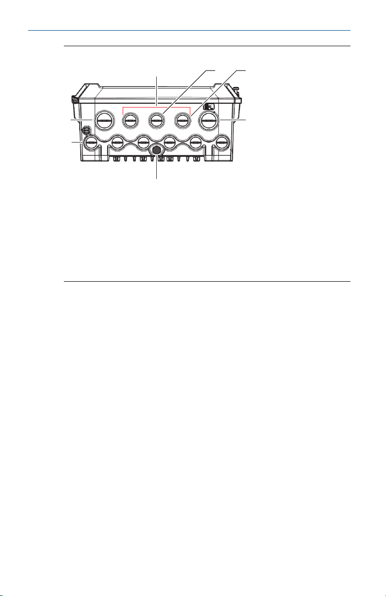
Figure 2-3: Cable Entries
A. Cable entry M25
B. Cable entries (6 x M20 x 1.5)
C. Cable entry M25 (power)
D. Membrane
E. Cable entries (3 x M20 x 1.5)
F. Cable entry for Ethernet connection ETH 1
G. Cable entry for Ethernet connection ETH 2
8 Rosemount 2460 Tank Hub
Page 9
G
H
I
A
B
C
D
F
J
E
September 2020 Quick Start Guide
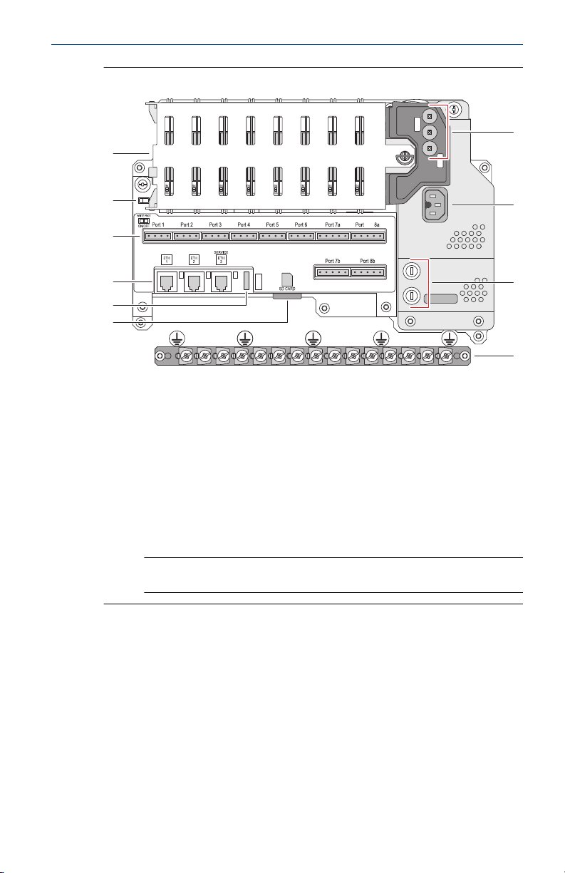
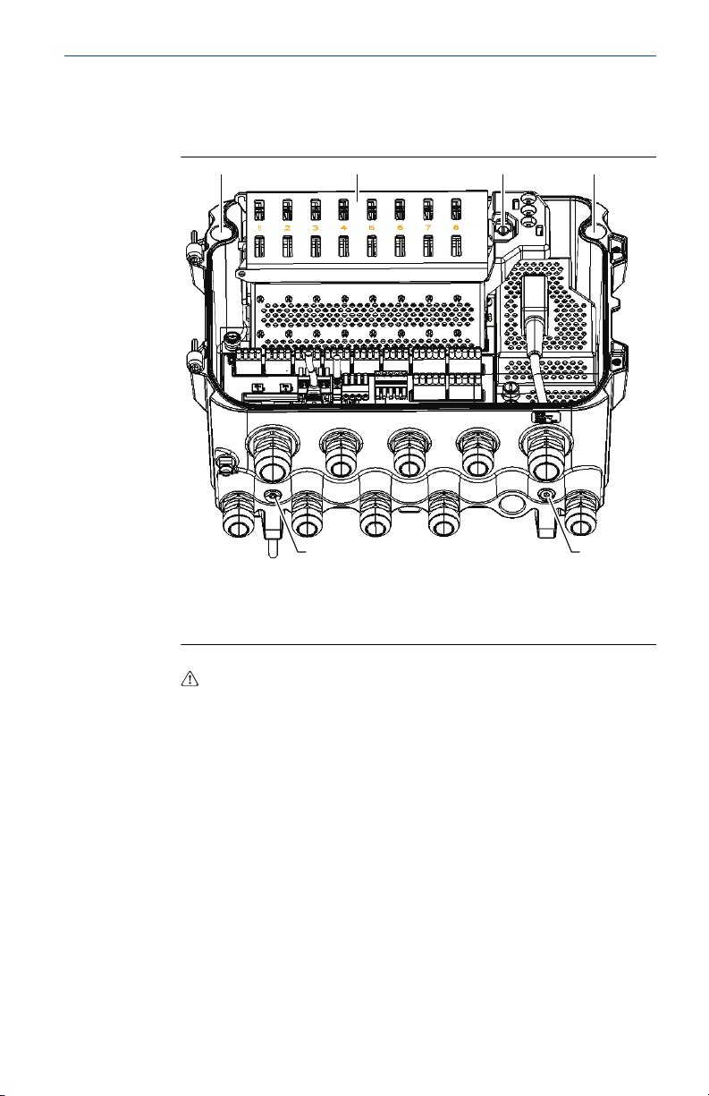
Figure 2-4: Inside the Rosemount 2460 System Hub
A. Communication boards
B. Write protection switch
C. Terminal board / ports (1 to 8)
D. Ethernet ports
E. USB port
F. SD memory card slot
G. LEDs (power=green, status=yellow, error=red)
H. Power input connector (IEC C16)
I. Fuses
J. Ground bar
Note
For signal/shield wire ground only.
Quick Start Guide 9
Page 10
OFF
ON
A
Quick Start Guide September 2020
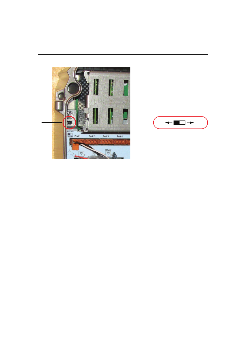
2.2.1 Write protection switch
The Rosemount 2460 System Hub is equipped with a write protection switch
for preventing unauthorized changes of the 2460 configuration database.
Figure 2-5: Write protection
A. Write protection switch
In addition to the switch, the Rosemount 2460 supports software write
protection.
10 Rosemount 2460 Tank Hub
Page 11

September 2020 Quick Start Guide
3 General information
3.1 Service support
For service support contact the nearest Emerson Automation Solutions /
Rosemount Tank Gauging representative. Contact information can be found
on the web site www.Emerson.com.
3.2 Product recycling/disposal
Recycling of equipment and packaging should be taken into consideration
and disposed of in accordance with local and national legislation/
regulations.
Quick Start Guide 11
Page 12

Quick Start Guide September 2020
4 Installation
4.1 Installation considerations
The Rosemount 2460 System Hub may be installed on various nonhazardous locations at the plant.
• In case the system hub is exposed to long periods of sunshine, a
sunshade should be used to prevent the system hub from being heated
to temperatures above the maximum operating temperature. Sunshade
is to be manufactured and designed locally to suit the installation.
• Ensure that environmental conditions are within specified limits.
• Ensure that the system hub is installed such that it is not exposed to
higher pressure and temperature than specified.
• Do not install the system hub in non-intended applications, for example
environments where it may be exposed to extremely intense magnetic
fields or extreme weather conditions.
• Use an external circuit breaker in order to make sure that power supply
can be safely disconnected when wiring and servicing the system hub.
The circuit breaker shall be easily accessible and appropriately labeled.
• In case devices from other vendors will be connected to the system hub,
ensure that correct modem cards are installed for the field ports that will
be used.
• Ensure that correct firmware version is used that supports the desired
communication options and features.
• Ensure that TankMaster version 6.B6 or higher is used for Rosemount
2460 configuration.
• TankMaster 6.C0 and higher is required for configuration of Enraf
communication on field ports.
• TankMaster 6.D0 and higher is required for configuration of redundant
system hubs.
Important
Check the system hub for any signs of damage prior to installation.
Ensure that O-rings and gaskets are in good condition.
Check that all modems are firmly mounted in their slots and cannot move.
Related information
Rosemount 2460 reference manual
12 Rosemount 2460 Tank Hub
Page 13

September 2020 Quick Start Guide
4.1.1 Installation planning
It’s recommended to plan the installation in order to ensure that all
components in the system are properly specified. The planning stage should
include the following tasks:
• Make a plan of the site and specify suitable locations for the devices
• Consider power budget
• Specify cabling and connections (for example whether devices will be
“daisy-chained” or not)
• Specify cable glands that will be needed for the various devices
• Specify location of terminators on the Tankbus (Rosemount 2410 Tank
Hub)
• Make a note of identification codes such as Unit ID/Device ID of each
device
• Assign communication addresses for level gauges and other tank devices
to be stored in the Tank Databases
Hub and Rosemount 2410 Tank Hub
See Electrical installation for more information on cables and glands.
(1)
of the Rosemount 2460 System
(1) See the Rosemount Tank Gauging System Configuration Manual (Document no.
00809-0300-5100) and the Rosemount 2410 Tank Hub Reference Manual
(Document no. 00809-0100-2410) for more information.
Quick Start Guide 13
Page 14
M6
M6
Quick Start Guide September 2020
4.2 Mechanical installation
The housing of the Rosemount 2460 is designed with four holes for
attaching it to a wall using four screws. See also Mechanical Installation
Drawing D7000001-927 for further information.
Prerequisites
Note
Ensure that the Rosemount 2460 is installed in a way that minimizes
vibration and mechanical shock.
Procedure
1. Mark the positions of the four screws to be used for attaching the
2460 to the wall. A mounting template (see Figure 4-1) is shipped
with the 2460 which may be used for this purpose.
2. Drill four holes with appropriate size to fit screw diameter 6 mm.
3. Loosen the two screws (M6 x 2) on the Rosemount 2460 housing that
keep the lid in closed position and open the lid.
14 Rosemount 2460 Tank Hub
Page 15
A
A
A
ACB
September 2020 Quick Start Guide
4. Attach the Rosemount 2460 to the wall. There are four holes on the
housing to be used for the screws.
The required screw dimension is given by Figure 4-2.
A. Holes (x4) for attaching the system hub to a wall
B. Communication board compartment
C. Lock ring
5. Ensure that the Lock ring (C) on the cover to the communication
board compartment is folded so that it does not prevent the lid from
being properly closed. Close the lid and ensure that it is fully engaged
to prevent water from entering the terminal compartment. Torque
the two screws to 4 Nm (35 in.-lb).
Quick Start Guide 15
Page 16
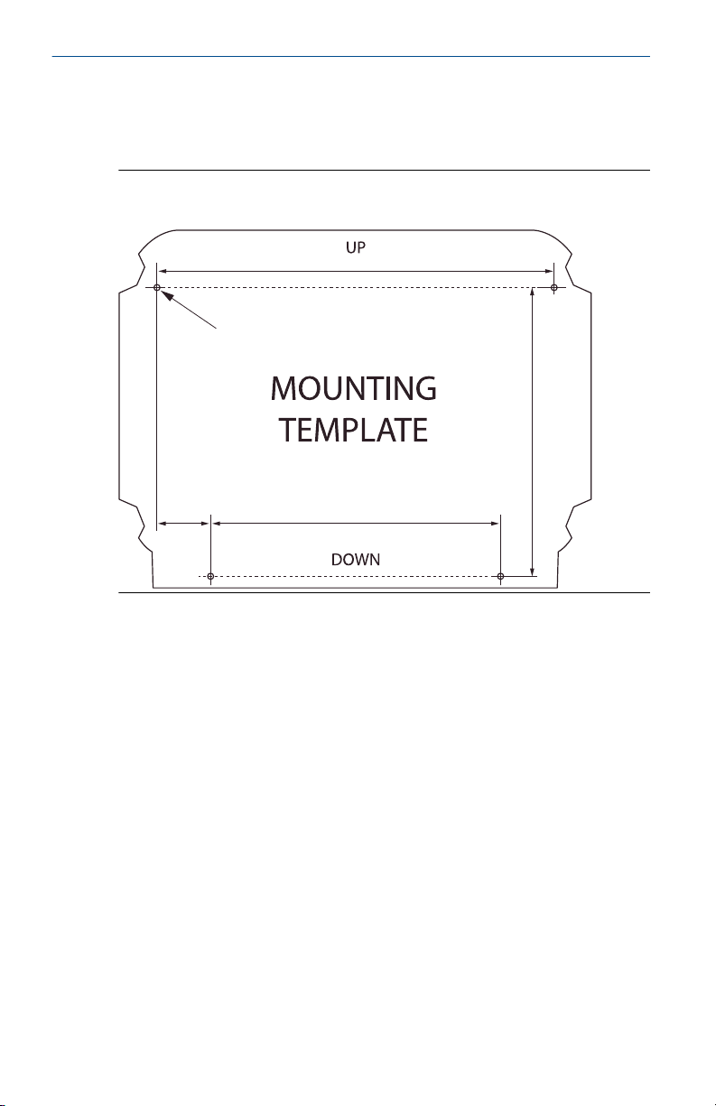
292 mm
Ø 6 mm (4x)
214 mm
39 mm
213 mm
Quick Start Guide September 2020
4.2.1 Mounting template
A mounting template is shipped with the Rosemount 2460 which can be
used to mark the position of the holes (see Figure 4-1).
Figure 4-1: Mounting Template with Hole Pattern for the Rosemount
2460 System Hub
Make sure that the four screws meet the specifications given in Figure 4-2.
16 Rosemount 2460 Tank Hub
Page 17
A
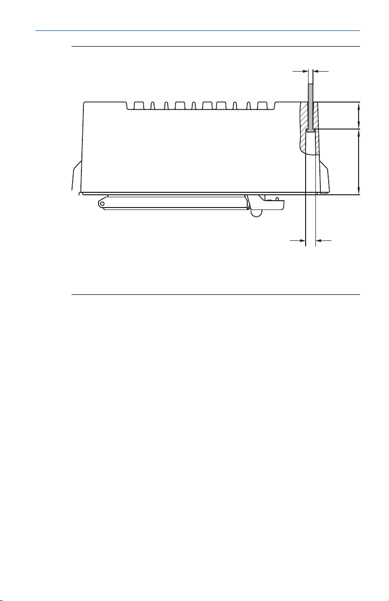
36 (4x)
87
B
September 2020 Quick Start Guide
Figure 4-2: Rosemount 2460 System Hub Dimensions
A. Four holes Ø 6.5 mm
B. Ø 12.5 mm (4x); Maximum dimension of screw head
Dimensions are in mm.
Quick Start Guide 17
Page 18

Quick Start Guide September 2020
4.3 Electrical installation
4.3.1 Electrical installation drawing
See Electrical Installation Drawing D7000001-928 for further information.
4.3.2 Cable entries
The Rosemount 2460 housing has nine M20 x 1.5 and two M25 x 1.5 entries.
Connections must be made in accordance with local or plant electrical
codes.
Make sure that unused cable entries are properly sealed to prevent moisture
or other contamination from entering the terminal board compartment of
the electronics housing.
NOTICE
Thread sealing (PTFE) tape or paste on male threads of conduit is required to
provide a water/dust tight conduit seal and to meet the required degree of
ingress protection as well as to enable future removal of the plug/gland.
Use the enclosed metal plugs to seal unused cable entries in order to achieve
required level of ingress protection. The plastic plugs mounted at delivery
are not sufficient as seal.
4.3.3 Power supply
The Rosemount 2460 System Hub accepts supply voltage 100 - 250 Vac
(50/60 Hz) and 24 - 48 Vdc.
Note
The Rosemount 2460 is polarity insensitive for DC voltage input.
4.3.4 Cable selection for power supply
Appropriate cross sectional area of wires must be used in order to prevent a
high voltage drop to the connected device. Recommended cable size is 0.75
mm2 to 2.1 mm2 (18 AWG to 14 AWG) in order to minimize the voltage
drop.
4.3.5 Grounding
The housing should always be grounded in accordance with national and
local electrical codes. Failure to do so may impair the protection provided by
the equipment. The most effective grounding method is direct connection
to earth ground with minimal impedance.
There is a grounding screw on the housing which is identified by ground
symbol
18 Rosemount 2460 Tank Hub
.
Page 19

September 2020 Quick Start Guide
Inside the Rosemount 2460’s terminal compartment there is a ground bar
with screw connections identified by ground symbols . The ground bar
shall only be used for connecting signal related ground wires, e.g. shield
ground connections from the field bus harness. The protective earth ground
connection shall be connected to the system hub via the dedicated power
board IEC plug and the external grounding screw on the housing.
Connect shield to ground at one end only, otherwise a ground loop may
occur.
NOTICE
Grounding the device via threaded conduit connection may not provide
sufficient ground.
Quick Start Guide 19
Page 20

Quick Start Guide September 2020
4.3.6 Connecting to a Rosemount 2460 System Hub
There are several ways to connect a Rosemount 2460 System Hub to a host
system:
• from a Host Port using TRL2 bus
• from a Host Port using RS232 or RS485
• via Ethernet Eth1 port
The TRL2 Bus requires a twisted and shielded pair cable with a crosssectional area of 0.50 to 2.5 mm2 (20 to 14 AWG). A Rosemount 2180 Field
Bus Modem (FBM) is used to connect the system hub to TankMaster or other
host computer.
A service PC can be connected to the Ethernet Eth3 port for configuration
and maintenance.
For RS232 communication, wiring cross-sectional area must be at least 0.25
mm2 (24 AWG or similar). The typical maximum length of the RS232
connection is 30 m at baud rate 4800.
Table 4-1: Data Rate and Maximum Distances for RS232 Communication
Baud rate (bps) Distance (m)
2400 60
4800 30
9600 15
19200 7.6
Communication ports for hosts and field devices
The Rosemount 2460 System Hub has eight ports for communication
interface boards. It is equipped with interface boards for field device
communication and host communication. The specific configuration is
specified in the ordering information. Communication boards can easily be
exchanged if needed.
Port 8 is used for TankMaster communication. Port 7 is used for host or
TankMaster communication as specified in the ordering information.
Port 1 to Port 4 are used for field device communication.
Ports 5 and 6 can be used for host or field device communication as specified
in the ordering information. This allows you to vary the number of field and
host ports depending on the specific requirements.
Table 4-2 shows various configuration options for a system hub.
20 Rosemount 2460 Tank Hub
Page 21

September 2020 Quick Start Guide
Table 4-2: Port Configuration Options
Ports 1 2 3 4 5 6 7 8
Alternative 6+2 (standard) Field
Alternative 5+3 Field
Alternative 4+4 Field
Port
Port
Port
Field
Port
Field
Port
Field
Port
Field
Port
Field
Port
Field
Port
Field
Port
Field
Port
Field
Port
Field
Port
Field
Port
Host
Port
Field
Port
Host
Port
Host
Port
Host
Port
Host
Port
Host
Port
Host
Port
Host
Port
Host
Port
Quick Start Guide 21
Page 22

Quick Start Guide September 2020
4.3.7 Wiring
The terminal compartment has a terminal board for connecting
communication buses to host systems and field devices. The terminal
compartment also has a connection for power supply. Ethernet connections
are available for LAN communication.
Prerequisites
Note
Ensure that gasket and seats are in good condition prior to mounting the
cover in order to maintain the specified level of ingress protection. The same
requirements apply for cable inlets and outlets (or plugs). Cables must be
properly attached to the cable glands.
Procedure
Ensure that the power supply is switched off.
1.
Note
If any uncertainty exists whether power supply is off or not, make
sure that loose cable ends don’t run through the cover on the power
board.
2. Loosen the two captive screws and open the lid (see Figure 4-3).
Note
The lid can be removed from the housing for easier access when
open more than 25°. Remove the locking ring and carefully slide the
lid upwards 21 mm or more. Be careful not to drop it on the floor.
3. Run wires through a cable gland. Install wiring with a drip loop in
such a way that the lower part of the loop is under the cable entry.
4. Connect wires to the terminal block.
• See Figure 4-4 for information on terminal block bus connections.
• See Wiring diagrams for examples on how to connect the
Rosemount 2460 to various host systems and field devices.
• For wiring of redundant system hubs see Figure 4.
5. Use the enclosed metal plugs to seal any unused cable entries.
Tighten the conduits/cable glands.
6.
7. Make sure that the Lock ring on the cover to the communication
board compartment is folded so that it does not prevent the lid from
being properly closed.
22 Rosemount 2460 Tank Hub
Page 23

A
E
B
D
C
C
B
September 2020 Quick Start Guide
8. Attach the lid in case it was removed from the housing and close
it. Torque the two screws to 4 Nm (35 in.-lb). Ensure that it is fully
engaged to prevent water from entering the terminal compartment.
Front view
Figure 4-3: Rosemount 2460 Front View
A. Lid
B. Lock ring
C. Captive screws x 2
D. Cover for communication board compartment
E. Power Board
Quick Start Guide 23
Page 24

D
A
C
B
E F G H
RXTXRXTXRXTXRXTXRXTXRXTXRXTXRX
POWER
LED BOARD
TX
Port 1
ETH
1
Port 2 Port 3 Port 4 Port 5 Port 6 Port 7a
Port 7b Port 8b
Port 8a
ETH3ETH
2
WRITE PROT
ON/OFF
SD CARD
SERVICE
I
Quick Start Guide September 2020
4.3.8 Terminal board and ports
Figure 4-4: Ports and Terminals
A. TRL2, RS485, ENRAF
B. Other interfaces
C. Write Protection Switch ON/OFF
D. Ethernet 1
E. Ethernet 2
F. Ethernet 3 / Service
G. USB A 2.0
H. SD card
I. Ground bar for cable shield
24 Rosemount 2460 Tank Hub
Page 25

September 2020 Quick Start Guide
Table 4-3: Terminal Assignment
Terminal Designation Function
Port 1 Field device Communication bus for field devices.
Port 2
Port 3
Port 4
Port 5 Field device/
Port 6
Port 7a Host/
Port 7b
Port 8a TankMaster Communication bus for TankMaster.
Port 8b
ETH 1 Standard
ETH 2 ETH 2 is an Ethernet communication bus for
ETH 3 Service Ethernet communication bus for service purposes.
USB A
2.0
SD card SD Memory card reader for saving log files.
Ground
bar
Host
TankMaster
Ethernet port
USB Port for USB stick. Can be used for saving log files.
For connection of cable shields.
Port 5 and 6 can be configured for field or host
communication.
Communication bus for host. Ports designated “a”
and “b” are connected in parallel. Supports electrical
interface TRL2, RS485, RS422, and RS232.
Ports designated “a” and “b” are connected in
parallel. This port supports electrical interface TRL2,
RS485, RS422, and RS232.
Ethernet communication bus.
ETH1 is used for DCS/host communication via
Modbus TCP.
In case the Rosemount 2460 is connected to a Local
Area Network (LAN) via Modbus TCP, ensure the
connection is secure and no unauthorized personnel
can grant access.
connection of redundant system hub. ETH 2 is
disabled for standalone systems, but enabled for
connection to redundant pair in redundant systems.
Use this port to access the Web interface for the
2460.
Quick Start Guide 25
Page 26

Pins internally connected in parallel
For daisy chain
Pins internally connected in parallel
(a)
(b)
Quick Start Guide September 2020
Pin mapping for 4 pole and 5 pole connectors
Figure 4-5: Port 1-6 for TRL2, RS485, and Enraf
Figure 4-6: Port 1-6 for Other Interfaces
Figure 4-7: Port 7-8
Bus connections
Table 4-4: Bus Connections to Port 1 - 6 Standard
Interface A B A
TRL2 (A and B polarity independent)
RS485 (2-wire)
(Modbus, Whessoe
550/660, GPE)
Internally referenced
to signal ground
Enraf BPM (A and B polarity independent)
(1) For daisy-chain
26 Rosemount 2460 Tank Hub
A B A B
(1)
(1)
B
Page 27

A
B
September 2020 Quick Start Guide
Table 4-5: Bus connections to Host Port 7- 8
Interface A B C D COM
TRL2 (A and B polarity
RS485 / 422
(1)
(2-wire)
RS485 / 422
(4-wire)
RS232 RxD TxD N/A N/A GND
(1) Recommended for redundant systems
independent)
A B N/A N/A GND
RD + (A’) RD - (B’) TD + (A) TD - (B) GND
N/A N/A N/A
Conductors
Ensure that you use cables suitable for the terminal blocks that are supplied
by Emerson for the Rosemount 2460 System Hub.
Table 4-6: Cables Suitable for Terminal Blocks Supplied by Emerson
Conductor connection Maximum (mm2) AWG
Solid 4 11
Flexible 2.5 13
Flexible, Ferrule with plastic collar 1.5 16
Figure 4-8: Conductor Stripping Length and Cross-sectional Area
A. Stripping length: 7 mm
B. Cross-sectional area, see Table 4-6
Quick Start Guide 27
Page 28

A
2460TAG:
S/N:
MFG (yymmdd):
DEVICE ID:
MAINS: 100-250VAC 50/60Hz, 24-48VDC 20W
A
Quick Start Guide September 2020
Figure 4-9: Stripping Length for Connection to Ground Bar
A. Stripping length: 15 mm
Cable glands
Figure 4-10: Cable Entries with Glands and External Ground
A. External ground
Table 4-7: Tightening Torque (Nm) for Glands Supplied by Emerson
Item Thread
M20 M25
Body 7 10
Top Nut 4 7
Table 4-8: Cable Diameter (mm) for Glands
Thread
M20 M25
Cable Ø 6 - 13 9 - 17
28 Rosemount 2460 Tank Hub
Page 29

C
A
B
10
4
September 2020 Quick Start Guide
4.3.9 Ground lug
Figure 4-11: Ground Lug Dimensions
A. Ground lug
• Cable lug thickness maximum 4 mm
• Cable lug height maximum 10 mm
B. Cable size minimum 4 mm2 or AWG 11
C. External ground screw M5
Quick Start Guide 29
Page 30

L+
N
A
B
Quick Start Guide September 2020
4.3.10 Power supply connection
Figure 4-12: Power Supply Connection
A. 24 - 48 Vdc; 100 - 250 Vac; 50 - 60 Hz; Max 20 W
B. Protective ground
Power connector
Note
Connector is of type IEC C16.
Note
Connector is supplied by factory.
Figure 4-13: Power Connector Supplied by Emerson
Note
Use connector type IEC C16 only.
30 Rosemount 2460 Tank Hub
Page 31

September 2020 Quick Start Guide
Table 4-9: Torque Values for Power Connector Assembly
Item Max torque
Terminals 0.8 Nm
Cable clamp 1.2 Nm
Cover 1.2 Nm
Cable size
Table 4-10: Cable and Wire Size for Power Cord
Power cord connector supplied by manufacturer
Wire (x3) Max. 2.1 mm
Cable Max. 10 mm
2
Quick Start Guide 31
Page 32

A
C
D
D
E
F
G
E
F
B
Quick Start Guide September 2020
4.3.11 Wiring diagrams
The communication ports can be configured for various combinations of
field device and host communication. In the standard configuration Port1 to
Port 6 are connected to field devices and Port 7 and Port 8 are used for host
communication.
Figure 4-14: Rosemount 2460 System Hub Connected to Field Devices
and TankMaster PC
A. Rosemount TankMaster PC
B. Rosemount 2180 Field Bus Modem
C. Rosemount 2460 terminal board
D. Rosemount 2410 Tank Hub
E. Rosemount 5900S Radar Level Gauge
F. Rosemount 2240S Temperature Transmitter
G. Rosemount 2230 Field Display
Note that the actual Port configuration may differ from the example above .
See Connecting to a Rosemount 2460 System Hub for more information on
32 Rosemount 2460 Tank Hub
Page 33

C
B
A
September 2020 Quick Start Guide
configuration options for the Field and Host ports. See also installation
drawings for more information.
Figure 4-15 shows a wiring diagram with a Rosemount 2460 connected to a
host system via Modbus TCP.
Figure 4-15: Rosemount 2460 Connected to Host System Via Eth 1 Port
and Modbus TCP
A. Host system
B. Modbus TCP
C. Rosemount 2460 terminal board
Quick Start Guide 33
Figure 4-16 shows two system hubs in a redundant system. The Primary and
Backup system hubs are connected to each other via Ethernet port ETH2.
Page 34

A
C
B
D
A
Quick Start Guide September 2020
Figure 4-16: Example of Wiring Diagram with Redundant Rosemount
2460 System Hubs
A. TRL2 bus to host
B. Rosemount 2460 primary unit
C. Ethernet cable for redundancy connection
D. Rosemount 2460 backup unit
34 Rosemount 2460 Tank Hub
Page 35

September 2020 Quick Start Guide
5 Configuration
5.1 Overview
This section contains information on how to setup a Rosemount™ 2460
System Hub in a Rosemount Tank Gauging System. The description is based
on using the TankMaster Winsetup configuration program.
5.2 Safety messages
Instructions and procedures in this section may require special precautions
to ensure the safety of the personnel performing the operations.
Information that potentially raises safety issues is indicated by a warning
symbol (
operation preceded by this symbol.
WARNING
Failure to follow safe installation and servicing guidelines could result in
death or serious injury.
• Ensure only qualified personnel perform the installation.
• Use the equipment only as specified in this manual. Failure to do so may
• Do not perform any service other than those contained in this manual
). Refer to the following safety messages before performing an
impair the protection provided by the equipment.
unless you are qualified.
5.3
Setting up a Rosemount 2460 System Hub
5.3.1 Introduction
A Rosemount 2460 System Hub is easy to install and configure by using the
TankMaster Winsetup configuration program. The WinSetup installation
wizard guides you through the basic configuration to start up a Rosemount
2460.
Host communication via the Ethernet 1 port (ETH1) and Modbus TCP
protocol can be setup by using the Web based Graphical User Interface
(GUI). See the Rosemount 2460 Reference Manual for more information.
Quick Start Guide 35
Page 36

Quick Start Guide September 2020
5.3.2 Installation procedure
Installation of a Rosemount 2460 System Hub in a Rosemount Tank Gauging
system includes the following basic steps:
Procedure
1. Ensure that a plan is available for all tanks and devices with tag
names, communication addresses, number of temperature elements
and other data that is needed for a system setup.
2. In case devices from other vendors will be connected see the
Rosemount 2460 Reference Manual for more information.
3. Make sure that the Rosemount 2460 is properly wired and up and
running. Check that the Power LED is on and the Status LED indicates
normal operation.
4. (Redundancy). Make sure that the two system hubs are properly
wired as described in Wiring. See also Figure 4-16.
Note
Note that configuration of redundant Rosemount 2460 is supported
by TankMaster 6.D0 and higher versions.
5. Ensure that the TankMaster WinSetup configuration program is up
and running.
6. In TankMaster WinSetup, setup the appropriate protocol channel
the TankMaster host PC. This step will ensure that communication
between the TankMaster PC and the Rosemount 2460 is established.
7. In TankMaster WinSetup, start the device installation wizard and
configure the system hub:
a) In the WinSetup workspace, click the right mouse button on
the Devices folder and select Install new.
(2)
in
b) Specify device type (2460) and name tag.
c) Check that the correct communication channel is enabled
and verify communication with the TankMaster host
computer.
d) Verify that the Host ports and Field ports are using the right
protocols for communication with TankMaster work stations
or other host systems, and with field devices such as the
Rosemount 2410 Tank Hub and the Rosemount 5900S Radar
Level Gauge.
(2) See the Rosemount Tank Gauging System Configuration Manual for more
information on how to configure communication protocol channels.
36 Rosemount 2460 Tank Hub
Page 37

September 2020 Quick Start Guide
e) Configure the tank database. See configuration examples
that illustrate how the tank databases of the Rosemount
2460 and the Rosemount 2410 are related to each other in
Tank databases of the Rosemount 2460 and the Rosemount
2410.
f) (Redundancy). Perform a redundancy configuration in case
the system has a pair of redundant system hubs. This is
included as part of the installation wizard. See Redundancy
configuration for more information.
g) Finish the installation wizard and verify that the system hub
appears in the Rosemount TankMaster workspace. Now the
Rosemount 2460 will be able to communicate with the host
system and collect data from field devices.
8. In case the Rosemount 2460 communicates with a host system via
the Ethernet 1 port and Modbus TCP protocol, open the Web based
Graphical User Interface for configuration.
Related information
Rosemount Tank Gauging System Configuration manual
Rosemount 2460 Reference Manual
Quick Start Guide 37
Page 38

A
B
F
N
LJ
K
G
M
O
Q
C
E
D
D
C
IH
P
R
Quick Start Guide September 2020
System architecture
Figure 5-1: Rosemount Tank Gauging System Architecture
A. Rosemount TankMaster J. TRL2; Enraf BPM; DCL; RS485
B. Modem K. Ethernet (ETH1)
C. Modbus TCP L. TRL2, RS485
D. Host/DCS M. Gauges and transmitters from
E. Plant network N. Rosemount 5900S Radar Level
other vendors
Gauge
F. Rosemount 2460 System Hub O. Rosemount 2240S Temperature
Transmitter
G. Field/Host Ports P. Rosemount 2410 Tank Hub
H. TRL2 Q. Rosemount 2230 Display
I. RS232, RS485 R. Tankbus
38 Rosemount 2460 Tank Hub
Page 39

September 2020 Quick Start Guide
5.3.3 Tank databases of the Rosemount 2460 and the Rosemount 2410
In a typical Rosemount Tank Gauging system, a Rosemount 2460 System
Hub collects measurement data from a number of tanks via one or more
Rosemount 2410 Tank Hubs. For proper communication with the control
room PC and the Rosemount TankMaster operator’s interface, Modbus
addresses need to be assigned to the field devices on the tank. These
addresses are stored in the system hub’s and tank hub’s tank databases.
In the tank hub’s database, the Rosemount 2240S Temperature Transmitter
and the Rosemount 2230 Graphical Field Display (and other non-level
devices) are handled as a single Auxiliary Tank Device (ATD). Two Modbus
addresses are used for each tank, one for the level gauge and one for the
ATD.
The ATD includes any supported non-level device such as the Rosemount
2240S Multi-Input Temperature Transmitter and the Rosemount 2230
Graphical Field Display. Other devices such as the Rosemount 3051S
Pressure Transmitter may also be included in the ATD. The ATD address
represents all these devices. Each position in the Rosemount 2460 tank
database represents one tank.
In case the level gauge is a Rosemount 5900S 2-in-1, you will need to
configure two level device addresses for the Rosemount 5900S gauge. See
the Rosemount Tank Gauging System Configuration Manual (Document No.
00809-0300-5100) for a detailed description of how to configure the tank
database with a Rosemount 5900S 2-in-1.
One Rosemount 2410 Tank Hub for each tank
In this example a Rosemount 2460 System Hub is connected to two tanks,
each of which has a separate Rosemount 2410 Tank Hub.
Each tank has a Rosemount 5900S Radar Level Gauge, a Rosemount 2240S
Multi-Input Temperature Transmitter, and a Rosemount 2230 Graphical
Field Display. The Modbus address configuration is summarized in Table 5-1.
Table 5-1: Example of Modbus Address Configuration for Rosemount
2410 Tank Hubs and Connected Devices on Two Tanks
Tank Rosemount 2410
Tank Hub
TK-1 101 1 101
TK-2 102 2 102
Rosemount 5900S
Level Gauge
Modbus Address
ATD (2230, 2240S)
For each tank, the Level Device address and ATD Modbus address in the
Rosemount 2460 System Hub’s tank database must be equal to the
corresponding addresses in the Rosemount 2410 Tank Hub’s tank database.
Quick Start Guide 39
Page 40

A
B
C
D
E
TK-1
TK-2
B
C
D
E
Quick Start Guide September 2020
Figure 5-2: Two Tanks Each of which Equipped with a Rosemount 2410
Tank Hub
A. Rosemount 2460 System Hub
B. Rosemount 2410 Tank Hub
C. Rosemount 2230 Graphical Field Display
D. Rosemount 5900S Level Gauge
E. Rosemount 2240S Temperature Transmitter
40 Rosemount 2460 Tank Hub
Page 41

September 2020 Quick Start Guide
Figure 5-3: Tank Databases in System Hub and Tank Hubs
A. Rosemount 2410 Tank Hub on tank TK-1
B. Rosemount 2460 System Hub
C. Rosemount 2410 Tank Hub on tank TK-2
Multiple tanks connected to a single Rosemount 2410 Tank Hub
In this example a Rosemount 2460 System Hub is connected to a
Rosemount 2410 Tank Hub that serves three tanks. The temperature device
on tank 1 has the same Modbus address as the tank hub itself. The other
temperature devices on tank 2 and 3 have separate Modbus addresses.
Figure 5-4 shows an example of a system with a Rosemount 2460 System
Hub connected to a Rosemount 2410 Tank Hub. The Rosemount 2410
collects measurement data from three tanks. Each tank is equipped with a
Rosemount 5408 Radar Level Transmitter, a Rosemount 2240S Temperature
Transmitter, and a Rosemount 2230 Graphical Field Display. The Modbus
address configuration is summarized in Table 5-2.
Table 5-2: Modbus Address Configuration for Tank Hub and Field
Devices on Three Tanks
Tank Rosemount 2410
Tank Hub
TK-1 101 1 101
TK-2 101 2 102
TK-3 101 3 103
Quick Start Guide 41
Rosemount 5408
Level Transmitter
Modbus Address
ATD (2230, 2240S)
Page 42

A
B
C
D
E
TK-1
TK-2
TK-3
Quick Start Guide September 2020
Note that each ATD has its own Modbus address. Only the first one has the
same address as the Rosemount 2410 Tank Hub.
Figure 5-4: Three Tanks Connected to a Single Rosemount 2410 Tank
Hub
A. Rosemount 2460 System Hub
B. Rosemount 2410 Tank Hub
C. Rosemount 2230 Graphical Field Display
D. Rosemount 5408 Level Transmitter
E. Rosemount 2240S Temperature Transmitter
In the tank database of the Rosemount 2410 Tank hub, the Rosemount
2240S temperature transmitter and the Rosemount 2230 display are
grouped into an Auxiliary Tank Device (ATD). The ATD Modbus address has
to be stored in the Temperature Device address field in the tank database of
the Rosemount 2460 System Hub as illustrated in Figure 5-5. The Modbus
addresses of the level devices must also be stored in both the 2410 and the
2460 tank databases.
42 Rosemount 2460 Tank Hub
Page 43

September 2020 Quick Start Guide
Figure 5-5: Tank Databases in System Hub and Tank Hubs
A. Tank Database for a Rosemount 2410 Tank Hub that serves three tanks
B. Rosemount 2460 System Hub
C. Level device address
D. Auxiliary Tank Device (ATD) address
Note that in this example a single Rosemount 2410 Tank Hub serves three
tanks. The tanks are mapped to tank position 1, 2, and 3 in the Rosemount
2410 Tank Hub’s tank database.
In the tank database of the Rosemount 2460 System Hub, you will have to
configure 2410 Tank Position in order to be able to configure the correct
Temperature Device Addresses for the three tanks.
Quick Start Guide 43
Page 44

Quick Start Guide September 2020
5.3.4 System setup
The System Values window lets you specify parameters and units for
inventory calculations.
Procedure
1. Log in to the Web interface.
2. Select Configuration → System Values.
Figure 5-6: System Parameters and Units
Manual values
Select the appropriate check boxes in case you like to use manual values for
ambient air temperature and pressure, and type the desired values into the
input fields.
Reference temperature
The Rosemount 2460 System Hub performs inventory calculations
according to the API Manual of Petroleum Measurement Standards Chapter 12,
Section 1, at the standard reference temperature 15°C (60°F). This is the
default reference temperature.
Other reference temperatures can be specified in the Reference
Temperature input field. Ensure that correct RT volume table, for example
54B-2004, is used for the product.
44 Rosemount 2460 Tank Hub
Page 45

September 2020 Quick Start Guide
System units
Level, Level Rate, Temperature, and Pressure units are configured in
TankMaster WinSetup configuration program.
Quick Start Guide 45
Page 46

Quick Start Guide September 2020
5.3.5 Redundancy configuration
Setting up a redundant pair of Rosemount 2460 System Hubs can be
performed by using TankMaster WinSetup or the system hub’s Web
Graphical User Interface.
Preconditions for redundancy setup
The following conditions must be met to allow setting up two Rosemount
2460 System Hubs for redundancy operation:
• The same firmware version on both System Hubs
• Firmware version 1.C0 or higher
• Rosemount TankMaster version 6.D0 or higher
• For Modbus TCP; Rosemount TankMaster version 6.F0 or higher
• No warnings or errors
• License;
— the same maximum number of tanks
— redundancy option enabled on both system hubs
— the same number of Modbus TCP clients
• The same modem board setup
modem locations)
• Hardware write protection disabled
• Software write protection disabled
Basically all model codes except Housing, Cable/Conduit Connections, and
Options need to be identical for the Primary and Backup system hubs.
(3)
(number of boards, modem type, and
(3) Modem boards supported for redundancy: TRL2 Modbus, RS485, Enraf BPM
46 Rosemount 2460 Tank Hub
Page 47

C
D
A B
E
J
K
M
L
G
H I
F
G
September 2020 Quick Start Guide
System Architecture with redundant system hubs
Figure 5-7: Rosemount Tank Gauging System Architecture with
Redundant System Hubs
A. Rosemount 2460 System Hub
H. Modbus TCP (Primary)
(backup)
B. Rosemount 2460 System Hub
I. Modbus TCP (Backup)
(primary)
C. Host System J. Rosemount 5900S Radar Level
Gauge
D. Modem K. Rosemount 2240S Temperature
E. Redundancy cable L. Rosemount 2230 Display
F. Field Ports M. Rosemount 2410 Tank Hub
G. Host Ports
Quick Start Guide 47
Transmitter
Page 48

Quick Start Guide September 2020
Redundancy setup in TankMaster WinSetup
This section describes the redundancy setup in the WinSetup configuration
wizard for the Rosemount 2460 System Hub.
Prerequisites
The installation wizard for the Rosemount 2460 includes the option to setup
a redundant pair of Rosemount 2460 System Hubs as long as certain
conditions are fulfilled. In case all requirements for pairing are fulfilled, the
following text appears: “Pairing is possible, Backup device ID:xx”.
Figure 5-8: Redundancy Page in WinSetup Installation Wizard
Procedure
Click the Create New Pair button to start the redundancy synchronization
procedure.
Figure 5-9: Redundancy Pairing
When finished, a message appears that the database synchronization was
successfully completed. The system hubs will be paired as a Primary and a
Backup device.
48 Rosemount 2460 Tank Hub
Page 49

September 2020 Quick Start Guide
Redundancy window
Once the synchronization process is successfully finished, the Redundancy
window presents the current status and other information for the two
system hubs.
Figure 5-10: Redundant System Hubs
Quick Start Guide 49
Page 50

Quick Start Guide September 2020
Table 5-3: Redundancy Configuration
Item Description
Manual Switch Over
button
State If the status is OK, a green check box is displayed. Otherwise
Device ID Each device has a unique identification number which can
Individual Modbus
address
Recent events Number of times that the Primary and Backup devices have
Switch to standalone
mode button
Configure button This button lets you configure specific redundancy options
Active/Passive mode can be changed manually. The Active
device communicates with the host system and responds to
requests for measurement data, status information, and
diagnostics. This option can be useful for testing that both
system hubs function properly as Active and Passive.
a list of warnings and errors will be displayed.
be used, for example, when setting up Modbus addresses.
The redundant system hubs can be given individual Modbus
addresses in case you need to be able to communicate
separately with each system hub.
changed to active state, as well various error messages and
warnings.
It is possible to un-pair the two devices in the redundancy
system by using the Switch to Standalone Mode button.
When un-pairing the system, the active device will change
mode to standalone. The passive device will load the default
configuration database (CDB) and the default
communication parameters (including Modbus address
245) to make sure it will not disturb communication on Host
and Field ports after un-pairing the system hubs.
Consequently, the host system will lose contact with the
backup device until proper communication settings are
reset.
such as fail-over, take-over, and passive device
communication.
Configure button
You may configure various options for fail-over and other redundancy
related issues. You may also set separate Modbus addresses for the two
system hubs.
Procedure
In the System Hub Redundancy window, click the Configure button to open
the 2460 System Hub Redundancy Configuration window.
50 Rosemount 2460 Tank Hub
Page 51

September 2020 Quick Start Guide
Figure 5-11: System Hub Redundancy Configuration
System hub redundancy window
Individual Modbus address
By setting individual Modbus addresses for the Primary and Backup devices,
a host system may communicate with each device separately. This is useful,
for example, for verifying the current status of each device.
Minimum Polling Interval
If the host system uses a longer poll interval in the communication than the
configured value, the system will report error.
Entry fields for Host Ports 5 and 6 will only be enabled if the ports are
configured as host ports. Entry fields for Modbus TCP will only be enabled if
Modbus TCP license option is enabled.
Quick Start Guide 51
Page 52

Quick Start Guide September 2020
Fail-over criteria
Table 5-4: Fail-over Criteria
Criteria Description
Configuration file error (default) Configuration database (CDB) is corrupt.
Host port modem error (default) A Host port modem has failed or been
Field port modem error (default) A Field port modem has failed or been
Field port communication failure No response from any field device on a Field
Field port communication failure
on...
Maximum number of Fail-overs per
hour (1..10)
removed.
removed.
port. This option is most useful for redundant
field bus wiring where each Rosemount 2460
has separate field bus wiring.
Individual port configuration for Field Port
communication failure.
Maximum number of fail-overs per hour in
order to prevent an oscillating behavior i.e.
switching back and forth between Primary
and Backup device. In case fail-overs tend to
occur frequently, the reason behind should
be investigated and fixed.
Take-over criteria
There may be situations when you would like the passive device to take over
as the active device even if no fail-over criteria is fulfilled. For example, in
case the active device does not respond to Host requests, the passive device
may take over and become the active device. The Active doesn’t reply on
Host port option does not work if the Primary and Backup system hubs are
wired to separate host ports which is the case when, for example, using the
RS232 communication interface.
Passive device communication
In case the Primary and Backup system hubs are connected to different ports
on the host system, the same Modbus address can be used for
communication with the two system hubs. Then there is no need to use
individual Modbus addresses for the Primary and Backup devices. When
communicating with a host system via RS232 interface, separate host ports
must be used, and the Allow Passive device to reply on common Modbus
address option needs to be enabled.
52 Rosemount 2460 Tank Hub
Page 53

September 2020 Quick Start Guide
Finish the installation wizard
Once the redundancy configuration is finished:
Procedure
In the 2460 System Hub Redundancy window, click the Next button.
Postrequisites
Finish the installation wizard as described in Installation procedure.
Quick Start Guide 53
Page 54

Quick Start Guide September 2020
Redundancy setup via Web graphical user interface
This section describes how to use the the Web graphical interface for
redundancy setup of a Rosemount 2460 System Hub. The setup includes
two basic steps:
• Paring; two system hubs are setup as a redundant pair
• Redundancy configuration; addresses and fail-over criteria are
configured
Pairing
Prerequisites
For the system hubs to be able to pair, ensure that the preconditions are
fulfilled.
Procedure
1. Log in to the Web interface.
2. Select the Redundancy tab.
3. Expand the Pair option.
4. Verify that the other system hub is pairable, i.e. all requirements for
pairing are marked with a green button.
5. If the two system hubs (Primary and Backup) are ready for pairing,
click the Pair button to start the synchronization process.
54 Rosemount 2460 Tank Hub
Page 55

September 2020 Quick Start Guide
Redundancy configuration
Once the synchronization is finished you may configure the system hubs for
redundancy operation.
Procedure
1. In the Web interface, select the Redundancy tab.
2. Expand the
Configuration option.
Quick Start Guide 55
Page 56

Quick Start Guide September 2020
3. Configure the device.
Example
Redundancy configuration overview
Table 5-5: Redundancy Configuration Overview
Item Description
Primary Device ID
Backup Device ID
Redundancy Status If status is OK, a green check box is displayed. You may
Manual switch over Active/Passive mode can be changed manually. The Active
Configuration See Table 5-6.
Unpair It is possible to un-pair the two devices in the redundancy
Each device has a unique identification number.
expand the Status list to view further details. In case status
is not OK, a list of warnings and errors will be displayed. See
also View redundancy state in TankMaster WinSetup.
device communicates with the host system and responds to
requests for measurement data, status information, and
diagnostics. This option can be useful for testing that both
system hubs function properly as Active and Passive.
system. When un-pairing the redundant system hubs, the
active device will change mode to standalone. The passive
device will load the default configuration database and the
default Modbus address (245) to make sure it will not
disturb communication on Host and Field ports after
unpairing the system hubs.
56 Rosemount 2460 Tank Hub
Page 57

September 2020 Quick Start Guide
Table 5-6: Redundancy Configuration Options
Item Description
Common Modbus
Address
Specific Modbus
Address for Primary
Device / Specific
Modbus Address for
Backup Device
Passive device
responds on common
address
Max Fail-Overs per
Hour
Fail-over criteria See Fail-over criteria.
Take-over criteria See Take-over criteria.
Use Modbus TCP as
main host interface
Common Modbus address is the standard setting. Primary
and Backup system hubs use the same Modbus address.You
may use this option in case Primary and Backup system
hubs are connected to different host ports. Then the same
Modbus address can be used instead of individual
addresses.
The redundant system hubs can be given individual Modbus
addresses in case you need to be able to communicate
separately with each system hub. This is useful, for
example, for verifying the current status of each device.
See Passive device communication.
Maximum number of fail-overs per hour in order to prevent
an oscillating behavior i.e. switching back and forth
between Primary and Backup device. In case fail-overs tend
to occur frequently, the reason behind should be
investigated and fixed.
If Modbus TCP is used for communication with the host
system and no Host Ports are used, it is necessary to enable
this function. If not set the passive system hub will not take
over as active device when the active is powered off or fails.
Quick Start Guide 57
Page 58

Quick Start Guide September 2020
6 Operation
6.1 Start-up procedure
When the system hub is starting up, the LEDs are lit up and turned off in a
certain order to indicate proper operation. In case an error is detected
during the start-up procedure the red LED remains turned on.
Start-up:
1. All LEDs are turned on
2. Within 0.5 seconds the yellow (Status) LED is turned off.
3. When the start-up procedure is finished, the red (error) LED is turned
off. In case an error is detected during the start-up procedure, the
error LED will start blinking according to the appropriate error code.
4. The green (power) LED remains lit when the system hub is powered
on.
6.2 Runtime operation
After the start-up procedure is finished the system hub enters runtime
mode.
The red Error LED will be turned off. If an error occurs, the LED will start to
blink.
In runtime mode the yellow status LED will blink at a rate given by the
current operational mode.
58 Rosemount 2460 Tank Hub
Page 59

September 2020 Quick Start Guide
A Product certifications
Rev 3.1
A.1 European directive information
The most recent revision of the EU Declaration of Conformity can be found
at Emerson.com/Rosemount.
A.2 Ordinary location certification
As standard, the Rosemount 2460 System Hub has been examined and
tested to determine that the design meets the basic electrical, mechanical,
and fire protection requirements by a nationally recognized test laboratory
(NRTL) as accredited by the Federal Occupational Safety and Health
Administration (OSHA).
Certificate
Standards
Markings
2735155
CAN/CSA-C22.2 No. 61010-1-12; UL Std. No. 61010-1
(3rd Edition);
Rated 24-48 V dc, 100-250 V ac, 20 W, 50/60 Hz;
Ambient rated -40 to +70 °C
A.3 Electromagnetic compatibility compliance
FCC
This device complies with Part 15 of the FCC Rules.
Standards
FCC 47 CFR Part 15B, 15.107 Conducted emission class
A, 15.109 Radiated Emission class A
A.4 Custody transfer certifications
OIML custody transfer
Certificate
More custody transfer certificates can be found at Emerson.com/Rosemount
R85-2008-SE-11.01
Quick Start Guide 59
Page 60

Quick Start Guide September 2020
A.5 Declaration of Conformity
The most recent revision of the EU Declaration of Conformity for the
Rosemount 2460 can be found at Emerson.com/Rosemount.
Figure A-1: Rosemount 2460 EU Declaration of Conformity (page 1)
60 Rosemount 2460 Tank Hub
Page 61

September 2020 Quick Start Guide
Figure A-2: Rosemount 2460 EU Declaration of Conformity (page 2)
Quick Start Guide 61
Page 62

Quick Start Guide September 2020
62 Rosemount 2460 Tank Hub
Page 63

September 2020 Quick Start Guide
Quick Start Guide 63
Page 64

Global Headquarters and Europe
Regional Office Tank Gauging
Emerson Automation Solutions
Box 150
(Visiting address: Layoutvägen 1)
SE-435 23 Mölnlycke
Sweden
+46 31 337 00 00
+46 31 25 30 22
Sales.RTG@Emerson.com
*00825-0100-2460*
Quick Start Guide
00825-0100-2460, Rev. AA
September 2020
North America Regional Office Tank
Gauging
Emerson Automation Solutions
6005 Rogerdale Road
Mail Stop NC 136
Houston, TX 77072, USA
+1 281 988 4000 or +1 800 722 2865
Sales.RTG.HOU@Emerson.com
Latin America Regional Office
Emerson Automation Solutions
1300 Concord Terrace, Suite 400
Sunrise, FL 33323, USA
+1 954 846 5030
+1 954 846 5121
RMTLAContactUS@Emerson.com
Middle East and Africa Regional Office
Emerson Automation Solutions
Emerson FZE
P.O. Box 17033
Jebel Ali Free Zone - South 2
Dubai, United Arab Emirates
+971 4 8118100
+971 4 8865465
RTGMEA.Sales@Emerson.com
Linkedin.com/company/Emerson-
Automation-Solutions
Twitter.com/Rosemount_News
Facebook.com/Rosemount
Youtube.com/user/
RosemountMeasurement
Asia Pacific Regional Office
Emerson Automation Solutions
1 Pandan Crescent
Singapore 128461
+65 6777 8211
+65 6777 0947
Specialist-OneLevel.RMT-
AP@Emerson.com
©
2020 Emerson. All rights reserved.
Emerson Terms and Conditions of Sale are
available upon request. The Emerson logo is a
trademark and service mark of Emerson Electric
Co. Rosemount is a mark of one of the Emerson
family of companies. All other marks are the
property of their respective owners.
 Loading...