

Page 1
00825-0100-3226, Rev AA
Rosemount™ 226
Toroidal Conductivity Sensors
Quick Start Guide
May 2020
Page 2
Quick Start Guide May 2020
Safety information
WARNING
High pressure and temperature hazard
Failure to reduce the pressure and temperature may cause serious injury to personnel.
Before removing the sensor, reduce the process pressure to 0 psig and cool down the process
temperature.
CAUTION
Equipment damage
The wetted sensor materials may not be compatible with process composition and operating
conditions.
Application compatibility is entirely the operator's responsibility.
WARNING
Physical access
Unauthorized personnel may potentially cause significant damage to and/or misconfiguration of end
users’ equipment. This could be intentional or unintentional and needs to be protected against.
Physical security is an important part of any security program and fundamental to protecting your
system. Restrict physical access by unauthorized personnel to protect end users’ assets. This is true for
all systems used within the facility.
Contents
Description and specifications......................................................................................................3
Install........................................................................................................................................... 4
Calibration................................................................................................................................. 14
Maintaining and troubleshooting............................................................................................... 19
Accessories................................................................................................................................ 24
2 Emerson.com/Rosemount
Page 3
May 2020 Quick Start Guide
1 Description and specifications
1.1 Overview
The Rosemount 226 Sensor is a toroidal (inductive) conductivity sensor.
These sensors work well for measuring in highly conductive liquids up to 2
S/cm (2,000,000 μS/cm). Unlike metal electrode based conductivity sensors,
toroidal conductivity sensors, like the Rosemount 226, are resistant to
fouling, coating, and chemical attack.
Sensors are molded with highly corrosion-resistant glass-filled PEEK
(polyetheretherketone). The sensors include an integral Pt-100 RTD for
temperature compensation. With a large bore hole opening, the Rosemount
226 greatly resists plugging when used in liquids containing high amounts of
suspended solids. PEEK is not recommended for greater than 50 percent
concentrations (at 77 °F [25 °C]) of H2SO4, HNO3, and H3PO4. PEEK is not
recommended for use with HF at all.
1.2 Specifications
Table 1-1: Rosemount 226 Toroidal Conductivity Sensor Specifications
Description Material and units
Conductivity range Refer to transmitter Product Data Sheet.
Wetted materials Glass-filled PEEK, EPDM Gasket
Operating temperature 32 to 248 °F (0 to 120 °C)
Maximum pressure 295 psig (2135 kPa [abs])
Standard cable length 20 ft. (6.1 m)
Maximum cable length 200 ft. (61 m)
Process connections ⅞-in. 9 UNC threads for flange mounting
Weight/shipping weight 2 lb./3 lb. (1.0 kg/1.5 kg)
and 1-in. MNPT (with -80 option); see
Dimensional drawings for more details.
Quick Start Guide 3
Page 4

Quick Start Guide May 2020
2 Install
2.1 Unpack and inspect
Procedure
1. Inspect the shipping container(s). If there is damage, contact the
shipper immediately for instructions.
2. If there is no apparent damage, unpack the container(s).
3. Ensure that all items shown on the packing list are present.
If items are missing, contact your local Customer Care representative
4. Save the shipping container and packaging.
They can be used to return the instrument to the factory in case of
damage.
2.2 Install sensor
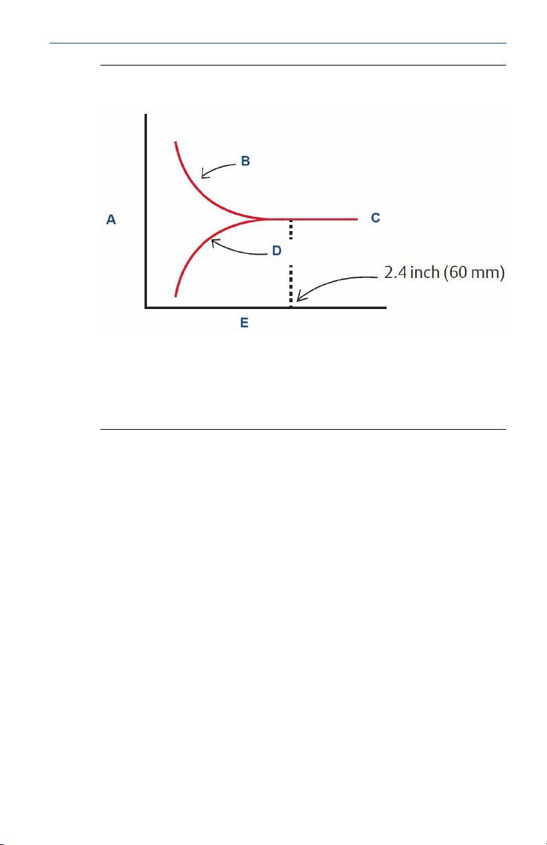
To ensure accurate readings, it is recommended the sensor be installed so
that there is at least 2.4 inches of clearance between the sensor and tank or
pipe walls. If installed too closely to the walls, an error in readings will be
induced by wall effects. Wall effects arise from the interaction between the
current induced in the sample by the sensor and nearby pipe or vessel walls.
As Figure 2-1 shows, the measured conductivity can either increase or
decrease depending on the wall material. This effect can be seen by
watching the conductivity readings change as the sensor is moved closer to
the sides of the pipe, tank, or beaker.
Ensure that the sensor is completely submerged in the process liquid.
Mounting the sensor in a vertical pipe run with flow running from bottom to
top is recommended. If the sensor must be installed in a horizontal pipe run,
mount the sensor in the 3 o’clock or 9 o’clock position.
4 Emerson.com/Rosemount
Page 5
May 2020 Quick Start Guide
Figure 2-1: Measured Conductivity as a Function of Clearance between
Sensor and Walls
A. Measured conductivity
B. Metal pipe
C. True conductivity
D. Plastic pipe
E. Distance to wall
Quick Start Guide 5
Page 6
Quick Start Guide May 2020
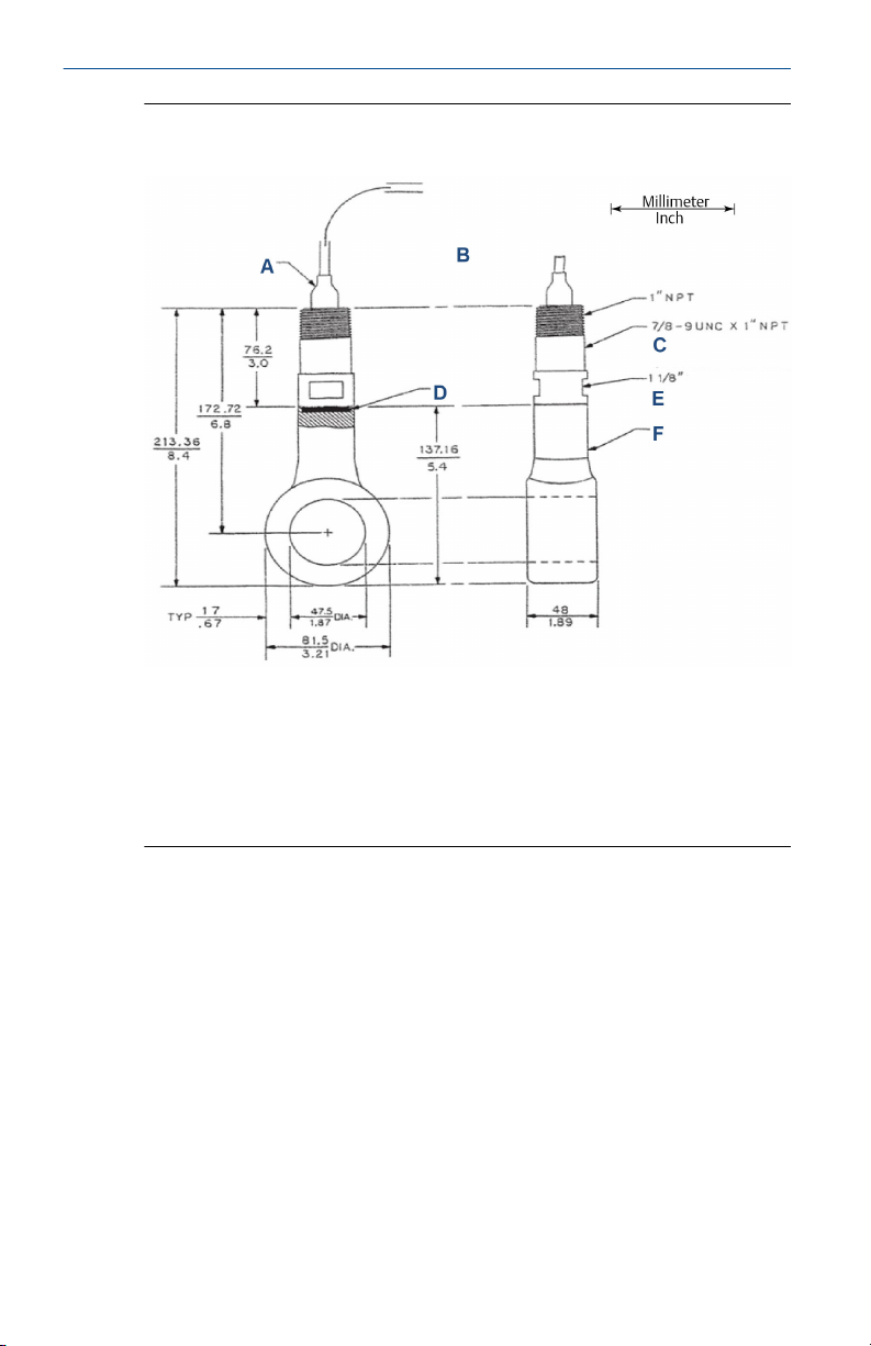
Figure 2-2: Rosemount 226 with 1-in. MNPT Process Connection
Mounting Adapter (-80 option) Dimensional Drawing
A. Boot
B. 20-ft. (6.1 m) cable
C. Adapter, PEEK, PN 33185-01 (included with code 80)
D. EPDM gasket
E. Wrench opening
F. One piece molded housing, PEEK
6 Emerson.com/Rosemount
Page 7
May 2020 Quick Start Guide
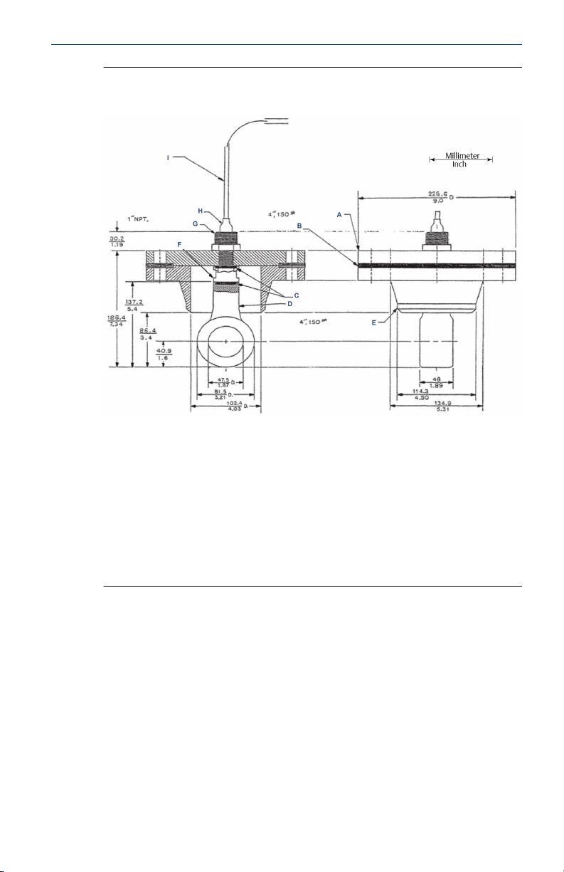
Figure 2-3: Rosemount 226 with ⅞-in. 9 UNC Thread and Insertion
through Flange Mounting Adapter (-81 option) Dimensional Drawing
A. Steel flange
B. Gasket
C. EPDM gaskets
D. One piece molded housing, PEEK
E. Welding neck steel flange
F. PEEK flange spacer 1-in. long
G. 304 stainless steel adapter for conduit
H. Boot
I. 20-ft. (6.1 m) cable
2.2.1 Submersion mounting
The sensor must be mounted in conduit or stand pipe to protect the back
end from process leakage. Use PTFE tape for a good seal.
2.2.2 Insertion Mounting
The sensor is designed to be mounted through any user-supplied flange. The
user is responsible for cutting a hole through the flange to fit the sensor. The
flange may be drilled and tapped for the sensor’s ⅞-in. 9 UNC thread.
Alternatively, a simple 15/16-in. (2.4 cm) drilled hole will accommodate the
⅞-in. 9 UNC thread.
Quick Start Guide 7
Page 8

Quick Start Guide May 2020
2.2.3 Sensor cable precautions
CAUTION
ELECTRICAL HAZARD
Cables run in the same conduit with power wiring or near heavy electrical
equipment may cause measurement errors and damage the sensor.
Do not run sensor cable in same conduit as the AC power wiring or near
heavy electrical equipment.
CAUTION
MOISTURE DAMAGE
Failure to properly seal the conduit may allow accumulated moisture in the
transmitter housing and damage the sensor and the transmitter.
Sensor cables routed in conduit must be sealed or plugged with sealing
compound.
8 Emerson.com/Rosemount
Page 9
May 2020 Quick Start Guide
2.3 Wire the sensor
For additional wiring information on this product, including sensor
combinations not shown here, please refer to Emerson.com/Rosemount-
Liquid-Analysis-Wiring.
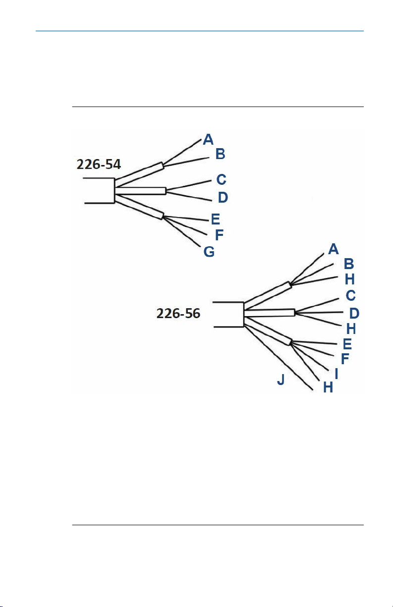
Figure 2-4: Wire Functions
A. Green - receive
B. Black - receive common
C. White - drive
D. Black - drive common
E. Green - resistance temperature device (RTD) in
F. White - RTD sense
G. Clear - RTD common
H. Clear - shield
I. Black - RTD common
J. Clear
Quick Start Guide 9
Page 10

Quick Start Guide May 2020
Figure 2-5: Wiring for Rosemount 226-54 and 226-56 Sensors to
Rosemount 1056 and 56 Transmitters
A. Clear
B. White
C. Green
D. Black
E. RTD return
F. RTD sense
G. RTD in
H. RTD shield
I. Receive common
J. Receive
K. Receive shield
L. Outer shield
M. Drive shield
N. Drive
O. Drive common
10 Emerson.com/Rosemount
Page 11

May 2020 Quick Start Guide
Figure 2-6: Wiring for Rosemount 226-54 and 226-56 Sensors to
Rosemount 1066 Transmitter
A. RTD return
B. RTD sense
C. RTD in
D. RTD shield
E. Green
F. White
G. Clear
H. Black
I. Receive B
J. Receive A
K. Receive shield
L. Drive B
M. Drive A
N. Drive shield
Quick Start Guide 11
Page 12

Quick Start Guide May 2020
Figure 2-7: Wiring for Rosemount 226-54 and 226-56 Sensors to
Rosemount 5081-T transmitter
A. Reserved
B. RTD shield
C. RTD common
D. RTD sense
E. RTD in
F. Receive shield
G. Receive common
H. Receive
I. Drive shield
J. Drive common
K. Drive
L. Clear
M. White
N. Green
O. Black
12 Emerson.com/Rosemount
Page 13

May 2020 Quick Start Guide
Figure 2-8: Wiring Sensors through a Remote Junction Box
A. Clear
B. White
C. Green
D. Black
E. Junction box
F. Interconnect cable
Quick Start Guide 13
Page 14

Quick Start Guide May 2020
3 Calibration
3.1 Sensor calibration
The nominal cell constant of the sensor is 1.2/cm. The error in cell constant
is about ± 10%, so conductivity readings made using the nominal cell
constant will have an error of at least ± 10%.
Wall effects as shown in Figure 2-1 will likely make the error greater.
There are two basic ways to calibrate a toroidal sensor: against a standard
solution or against a referee meter and sensor. A referee meter and sensor is
an instrument that has been previously calibrated and is known to be
accurate and reliable.
The referee instrument can be used to perform either an in-process or a grab
sample calibration. Regardless of the calibration method used, the
connected transmitter automatically calculates the cell constant once the
known conductivity is entered.
3.2 Calibrate against a standard solution
Calibration against a standard solution requires removing the sensor from
process piping. This calibration method is practical only if wall effects are
absent or if the sensor can be calibrated in a container identical to the
process piping. Ideally, the conductivity of the standard used should be close
to the middle of the range that the sensor will be used in. Generally, toroidal
conductivity sensors have good linearity and so standards greater than 5000
μS/cm at 25 °C may also be used.
Prerequisites
CAUTION
Before removing the sensor, be absolutely certain that the process pressure
is reduced to 0 psig and the process temperature is lowered to a safe level!
Immerse the rinsed sensor in the standard solution and adjust the
transmitter reading to match the conductivity of the standard. For an
accurate calibration several precautions are necessary:
Procedure
1. If wall effects are absent in the process installation, use a sufficiently
large container for calibration to ensure that wall effects are absent.
2. To check for wall effects, fill the container with solution and place the
sensor in the center submerged at least ¾ of the way up the stem.
3. Note the reading. Then move the sensor small distances from the
center and note the reading in each position.
14 Emerson.com/Rosemount
Page 15

May 2020 Quick Start Guide
The readings should not change.
4. If wall effects are present, be sure the vessel used for calibration has
exactly the same dimensions as the process piping.
5. Also, ensure that the orientation of the sensor with respect to the
piping is exactly the same in the process and calibration vessels.
Figure 3-1: Calibration Installation Orientation
A. Sensor in process piping
B. Flow
C. Blank flange
D. Pipe tee identical to process pipe tee
E. Sensor being calibrated
F. Standard solution
6. Turn off automatic temperature compensation in the transmitter.
This eliminates error in the cell constant.
7. Use a good quality calibrated thermometer to measure the
temperature of the standard solution.
The thermometer error should be less than ±0.1°C.
8. Allow adequate time for the solution and sensor to reach thermal
equilibrium.
If the sensor is being calibrated in an open beaker, keep the
thermometer far enough away from the sensor so it does not
introduce wall effects.
Quick Start Guide 15
Page 16

Quick Start Guide May 2020
If the sensor is being calibrated in a pipe tee or similar vessel, it will
probably be impractical to place the thermometer in the standard
solution.
9. Instead, put the thermometer in a beaker of water placed next to the
calibration vessel.
10. Let both come to thermal equilibrium with the ambient air before
continuing calibration.
Figure 3-2: Measuring Standard Temperature
A. Standard thermometer
B. Standard solution
C. Pipe tee
11. Make sure that the air bubbles are not adhering to the sensor.
An air bubble trapped in the toroid opening has a particularly severe
effect on the reading.
3.3
16 Emerson.com/Rosemount
Calibrate against a referee – in process
This method involves connecting the process and referee sensors in series
and allowing the process liquid to flow through both sensors. The process
sensor is calibrated by adjusting the process analyzer reading to match the
conductivity measured by the referee instrument.
Prerequisites
For a successful calibration, several precautions are necessary:
Procedure
1. If possible, adjust the conductivity of the process liquid so that it is
near the midpoint of the operating range.
Page 17

May 2020 Quick Start Guide
If this is not possible, adjust the conductivity so that it is at least 5000
μS/cm.
2. Orient the referee sensor so that air bubbles always have an easy
escape path and cannot get trapped.
Figure 3-3: Calibration with a Referee Instrument Example
A. Flow
B. Sensor in process piping
C. Sample valve
D. Referee sensor in flow cell
3. Tap and hold the flow cell in different positions to allow bubbles to
escape.
4. Turn off automatic temperature compensation in the transmitter.
This eliminates error in the cell constant.
Quick Start Guide 17
Page 18

Quick Start Guide May 2020
5. Keep tubing runs between the sensors short and adjust the sample
flow to as high a rate as possible.
Short tubing runs and high flow ensure that the temperature of the
liquid does not change as it flows from one sensor to another.
6. Wait for readings to stabilize before starting the calibration.
3.4 Calibrating against a referee - grab sample
This method is useful when calibration against a standard is impractical or
when in-process calibration is not feasible because the sample is hot,
corrosive, or dirty, making handling the waste stream from the referee
sensor difficult.
Prerequisites
The method involves taking a sample of the process liquid, measuring its
conductivity using a referee instrument, and adjusting the reading from the
process analyzer to match the measured conductivity. For a successful
calibration, several precautions are necessary:
Procedure
1. If possible, adjust the conductivity of the process liquid so that it is
near the midpoint of the operating range.
If this is not possible, adjust the conductivity so that it is at least 5000
μS/cm.
2. Take the sample from a point as close to the process sensor as
possible.
Be sure the sample is representative of what the sensor is measuring.
3. Keep temperature compensation with the transmitter turned on.
4. Confirm that the temperature measurements in both the process
and referee instruments are accurate, ideally to within ±0.5 °C.
5. Wait until readings are stable before starting the calibration.
18 Emerson.com/Rosemount
Page 19

May 2020 Quick Start Guide
4 Maintaining and troubleshooting
4.1 Maintaining the sensor
Generally, the only maintenance required is to keep the opening of the
sensor clear of deposits. Cleaning frequency is best determined by
experience.
CAUTION
Make sure that the sensor is cleaned of process liquid before handling.
4.2 Troubleshoot
4.2.1 Off-scale reading
Potential cause
Wiring is incorrect.
Recommended action
Verify and correct wiring.
Potential cause
Temperature element is open or shorted.
Recommended action
Check temperature element for open or short circuits.
See Figure 4-1.
Quick Start Guide 19
Page 20

Quick Start Guide May 2020
Figure 4-1: Sensor Resistance Check
Resistance between shield and any other wire: > 40 MΩ
A. Receive
B. Drive
C. Resistance temperature device (RTD)
D. Green
E. Black
F. White
G. Clear
Potential cause
Sensor is not in process stream.
Recommended action
Submerge sensor completely in process stream.
20 Emerson.com/Rosemount
Page 21

May 2020 Quick Start Guide
Potential cause
Sensor is damaged.
Recommended action
Perform isolation checks.
See Figure 4-1.
4.2.2 Noisy reading
Potential cause
Sensor is improperly installed in process stream.
Recommended action
Submerge sensor completely in process stream.
See Install.
Potential cause
Sensor cable is run near high voltage process stream.
Recommended action
Move cable away from high voltage conductors.
Potential cause
Sensor cable is moving.
Recommended action
Keep sensor cable stationary.
4.2.3 Reading seems wrong (lower or higher than expected)
Potential cause
Bubbles trapped in sensor.
Recommended actions
1. Install the sensor in a vertical pipe run with the flow against the
toroidal opening.
2. Increase flow if possible.
Potential cause
Sensor is not completely submerged in the process stream.
Recommended action
Confirm that the sensor is fully submerged in the process stream.
Quick Start Guide 21
Page 22

Quick Start Guide May 2020
See Install.
Potential cause
Wrong temperature correction algorithm is being used.
Recommended action
Check that the temperature correction is appropriate for the sample.
See transmitter Reference Manual for more information.
Potential cause
Temperature reading is inaccurate.
Recommended action
Disconnect the resistance temperature device leads and measure the
resistance between the in and common leads.
See Figure 4-1.
Resistance should be close to the value in Table 4-1.
Table 4-1: Resistance vs. Temperature for Temperature
Compensation (PT-100 RTD)
Temperature Resistance
10 °C (50 °F) 103.9 Ω
20 °C (68 °F) 107.8 Ω
25 °C (77 °F) 109.7 Ω
30 °C (86 °F) 111.7 Ω
40 °C (104 °F) 115.5 Ω
50 °C (122 °F) 119.4 Ω
Potential cause
The temperature response to sudden changes in temperature is slow.
Recommended action
Use a resistance temperature device (RTD) in a metal thermowell for
temperature compensation.
4.2.4 Sluggish response
Potential cause
Sensor is installed in dead area in piping.
22 Emerson.com/Rosemount
Page 23

May 2020 Quick Start Guide
Recommended action
Move sensor to a location more representative of the process liquid.
Potential cause
Slow temperature response to sudden changes in temperature.
Recommended action
Use a resistance temperature device in a metal thermowell for
temperature compensation.
Quick Start Guide 23
Page 24

Quick Start Guide May 2020
5 Accessories
Part number Description
23550-00 Remote junction box without preamplifier
23294-00 Unshielded interconnecting cable for Rosemount 1054A,
23294-05 Shielded interconnecting cable with additional shield wire for
33151-00 Gasket, EPDM (standard)
33151-01 Gasket, Viton®, Rosemount 226
33185-01 Mounting adapter, submersion, 9.8 ft. (3 m) length, 3.3 ft. (1
33185-02 Mounting adapter, insertion, 3.3 ft. (1 m) length, PEEK (with
33219-00 Mounting adapter, 304 stainless steel flange nut, 3.3 ft. (1 m)
9200276 Extension cable, unprepped (specify length) per foot
1054B, and 2054C. Can also be used with Rosemount 1056,
56, 5081, and 1066-T, but not recommended. Prepped,
specify length, per ft.
-03 option. For use with Rosemount 1056, 1066-T, 56, and
5081T. Prepped, specify length, per ft.
m) male national pipe thread (MNPT), PEEK
gasket)
MNPT for conduit
24 Emerson.com/Rosemount
Page 25

May 2020 Quick Start Guide
Quick Start Guide 25
Page 26

Quick Start Guide May 2020
26 Emerson.com/Rosemount
Page 27

May 2020 Quick Start Guide
Quick Start Guide 27
Page 28

GLOBAL HEADQUARTERS
6021 Innovation Blvd.
Shakopee, MN 55379
+1 866 347 3427
+1 952 949 7001
RMTNA.RCCPO@Emerson.com
00825-0100-3226, Rev. AA
Quick Start Guide
May 2020
NORTH AMERICA
Emerson Automation Solutions
8200 Market Blvd
Chanhassen, MN 55317
Toll Free +1 800 999 9307
F +1 952 949 7001
RMTNA.RCCPO@Emerson.com
MIDDLE EAST AND AFRICA
Emerson Automation Solutions
Emerson FZE
Jebel Ali Free Zone
Dubai, United Arab Emirates, P.O. Box
17033
+971 4 811 8100
+971 4 886 5465
RMTNA.RCCPO@Emerson.com
LinkedIn.com/company/Emerson-
Automation-Solutions
Twitter.com/rosemount_news
Facebook.com/Rosemount
Youtube.com/RosemountMeasurement
EUROPE
Emerson Automation Solutions
Neuhofstrasse 19a PO Box 1046
CH-6340 Baar
Switzerland
+41 (0) 41 768 6111
+41 (0) 41 768 6300
RMTNA.RCCPO@Emerson.com
ASIA-PACIFIC
Emerson Automation Solutions
1 Pandan Crescent
Singapore 128461
Republic of Singapore
+65 6 777 8211
+65 6 777 0947
RMTNA.RCCPO@Emerson.com
©
2020 Emerson. All rights reserved.
The Emerson logo is a trademark and service
mark of Emerson Electric Co. Rosemount is a
mark of one of the Emerson family of companies.
All other marks are the property of their
respective owners.
 Loading...