

Page 1

00809-0100-4140, Rev AA
Rosemount™ 2140 Level Detector
Vibrating Fork
Reference Manual
January 2017
Page 2

Page 3

Reference Manual
00809-0100-4140, Rev AA
Contents
1Section 1: Introduction
2Section 2: Configuration
Contents
January 2017
1.1 Models covered . . . . . . . . . . . . . . . . . . . . . . . . . . . . . . . . . . . . . . . . . . . . . . . . . . . . . . . 1
1.2 Point level detector overview. . . . . . . . . . . . . . . . . . . . . . . . . . . . . . . . . . . . . . . . . . . .1
1.3 Using this manual. . . . . . . . . . . . . . . . . . . . . . . . . . . . . . . . . . . . . . . . . . . . . . . . . . . . . . 2
1.4 Product recycling/ disposal . . . . . . . . . . . . . . . . . . . . . . . . . . . . . . . . . . . . . . . . . . . . . 3
2.1 Safety messages. . . . . . . . . . . . . . . . . . . . . . . . . . . . . . . . . . . . . . . . . . . . . . . . . . . . . . .5
2.2 Overview . . . . . . . . . . . . . . . . . . . . . . . . . . . . . . . . . . . . . . . . . . . . . . . . . . . . . . . . . . . . . 5
2.3 Get started with your preferred configuration tool . . . . . . . . . . . . . . . . . . . . . . . . . 6
2.3.1 AMS Device Manager . . . . . . . . . . . . . . . . . . . . . . . . . . . . . . . . . . . . . . . . . . . . 6
2.3.2 Field Communicator. . . . . . . . . . . . . . . . . . . . . . . . . . . . . . . . . . . . . . . . . . . . . 7
2.3.3 Local Operator Interface (LOI) . . . . . . . . . . . . . . . . . . . . . . . . . . . . . . . . . . . . 7
2.4 Switching HART Revision . . . . . . . . . . . . . . . . . . . . . . . . . . . . . . . . . . . . . . . . . . . . . . .8
2.4.1 Switching HART revision with a generic menu . . . . . . . . . . . . . . . . . . . . . . 8
2.4.2 Switching HART revision with Field Communicator . . . . . . . . . . . . . . . . . . 9
2.4.3 Switching HART Revision with AMS Device Manager . . . . . . . . . . . . . . . . . 9
2.4.4 Switching HART revision with Local Operator Interface. . . . . . . . . . . . . . . 9
2.5 Configuration basics . . . . . . . . . . . . . . . . . . . . . . . . . . . . . . . . . . . . . . . . . . . . . . . . . .10
2.5.1 Setting the security switch . . . . . . . . . . . . . . . . . . . . . . . . . . . . . . . . . . . . . . 10
2.5.2 Setting the loop to manual . . . . . . . . . . . . . . . . . . . . . . . . . . . . . . . . . . . . . .10
2.6 Configure device using Guided Setup . . . . . . . . . . . . . . . . . . . . . . . . . . . . . . . . . . .10
2.6.1 Guided setup on the AMS Device Manager . . . . . . . . . . . . . . . . . . . . . . . .10
2.6.2 Guided setup on the Field Communicator . . . . . . . . . . . . . . . . . . . . . . . . . 10
2.6.3 Guided setup on the LOI . . . . . . . . . . . . . . . . . . . . . . . . . . . . . . . . . . . . . . . . 11
2.7 Verify the configuration before installation . . . . . . . . . . . . . . . . . . . . . . . . . . . . . .11
2.7.1 Verifying configuration (Field Communicator or AMS) . . . . . . . . . . . . . . 11
2.7.2 Verifying configuration (LOI) . . . . . . . . . . . . . . . . . . . . . . . . . . . . . . . . . . . . 12
2.7.3 Dynamic variables configuration . . . . . . . . . . . . . . . . . . . . . . . . . . . . . . . . . 13
2.8 Basic setup. . . . . . . . . . . . . . . . . . . . . . . . . . . . . . . . . . . . . . . . . . . . . . . . . . . . . . . . . . .14
2.8.1 Sensor operation mode . . . . . . . . . . . . . . . . . . . . . . . . . . . . . . . . . . . . . . . . . 14
Contents
2.8.2 Sensor output delay . . . . . . . . . . . . . . . . . . . . . . . . . . . . . . . . . . . . . . . . . . . .16
2.8.3 Media density. . . . . . . . . . . . . . . . . . . . . . . . . . . . . . . . . . . . . . . . . . . . . . . . . . 17
2.8.4 Media learn. . . . . . . . . . . . . . . . . . . . . . . . . . . . . . . . . . . . . . . . . . . . . . . . . . . .19
2.8.5 Allowable change in dry fork frequency . . . . . . . . . . . . . . . . . . . . . . . . . . . 21
I
Page 4

Contents
January 2017
Reference Manual
00809-0100-4140, Rev AA
2.8.6 Sensor fault delay . . . . . . . . . . . . . . . . . . . . . . . . . . . . . . . . . . . . . . . . . . . . . .22
2.8.7 Analog output type and operating modes . . . . . . . . . . . . . . . . . . . . . . . . .23
2.8.8 Analog output range points . . . . . . . . . . . . . . . . . . . . . . . . . . . . . . . . . . . . . 26
2.8.9 Scaled Variable damping . . . . . . . . . . . . . . . . . . . . . . . . . . . . . . . . . . . . . . . .28
2.9 Local Operator Interface (LOI) display . . . . . . . . . . . . . . . . . . . . . . . . . . . . . . . . . . .29
2.9.1 Electronics temperature units . . . . . . . . . . . . . . . . . . . . . . . . . . . . . . . . . . .30
2.10Detailed setup . . . . . . . . . . . . . . . . . . . . . . . . . . . . . . . . . . . . . . . . . . . . . . . . . . . . . . .31
2.10.1 HART (re-mapping dynamic variables) . . . . . . . . . . . . . . . . . . . . . . . . . . . . 31
2.10.2 Configuring alarm and saturation levels . . . . . . . . . . . . . . . . . . . . . . . . . . .33
2.10.3 Configuring process alerts. . . . . . . . . . . . . . . . . . . . . . . . . . . . . . . . . . . . . . .35
2.10.4 Configuring Scaled Variable . . . . . . . . . . . . . . . . . . . . . . . . . . . . . . . . . . . . .36
2.11Configuring burst mode (optional) . . . . . . . . . . . . . . . . . . . . . . . . . . . . . . . . . . . . .38
2.12System readiness. . . . . . . . . . . . . . . . . . . . . . . . . . . . . . . . . . . . . . . . . . . . . . . . . . . . .40
2.12.1 Confirm correct Device Driver (DD). . . . . . . . . . . . . . . . . . . . . . . . . . . . . . .40
2.13Establishing multi-drop communications (optional) . . . . . . . . . . . . . . . . . . . . . .40
2.13.1 Communicating with a multi-dropped level detector . . . . . . . . . . . . . . .41
2.13.2 Changing a level detector polling address . . . . . . . . . . . . . . . . . . . . . . . . .42
2.14Configuring level detector security . . . . . . . . . . . . . . . . . . . . . . . . . . . . . . . . . . . . .42
2.14.1 Setting the security switch . . . . . . . . . . . . . . . . . . . . . . . . . . . . . . . . . . . . . . 43
2.14.2 HART Lock. . . . . . . . . . . . . . . . . . . . . . . . . . . . . . . . . . . . . . . . . . . . . . . . . . . . . 44
2.14.3 Configuration button lock . . . . . . . . . . . . . . . . . . . . . . . . . . . . . . . . . . . . . . .44
2.14.4 Local Operator Interface (LOI) password . . . . . . . . . . . . . . . . . . . . . . . . . . 45
2.15Setting the alarm switch . . . . . . . . . . . . . . . . . . . . . . . . . . . . . . . . . . . . . . . . . . . . . .46
3Section 3: Hardware Installation
3.1 Safety messages. . . . . . . . . . . . . . . . . . . . . . . . . . . . . . . . . . . . . . . . . . . . . . . . . . . . . .47
3.2 Considerations before installation . . . . . . . . . . . . . . . . . . . . . . . . . . . . . . . . . . . . . .48
3.2.1 Safety considerations . . . . . . . . . . . . . . . . . . . . . . . . . . . . . . . . . . . . . . . . . . .48
3.2.2 Environmental considerations . . . . . . . . . . . . . . . . . . . . . . . . . . . . . . . . . . .48
3.2.3 Application considerations . . . . . . . . . . . . . . . . . . . . . . . . . . . . . . . . . . . . . .49
3.2.4 Installation considerations . . . . . . . . . . . . . . . . . . . . . . . . . . . . . . . . . . . . . . 51
3.2.5 Installation examples . . . . . . . . . . . . . . . . . . . . . . . . . . . . . . . . . . . . . . . . . . .56
3.3 Installation procedures . . . . . . . . . . . . . . . . . . . . . . . . . . . . . . . . . . . . . . . . . . . . . . . .57
3.3.1 Process connection seals . . . . . . . . . . . . . . . . . . . . . . . . . . . . . . . . . . . . . . . .57
3.3.2 Correct fork alignment. . . . . . . . . . . . . . . . . . . . . . . . . . . . . . . . . . . . . . . . . .58
3.3.3 Tightening the threaded Rosemount 2140 . . . . . . . . . . . . . . . . . . . . . . . . 60
3.3.4 Insulation . . . . . . . . . . . . . . . . . . . . . . . . . . . . . . . . . . . . . . . . . . . . . . . . . . . . .60
II
Contents
Page 5

Reference Manual
00809-0100-4140, Rev AA
4Section 4: Electrical Installation
5Section 5: Operation and Maintenance
Contents
January 2017
4.1 Safety messages. . . . . . . . . . . . . . . . . . . . . . . . . . . . . . . . . . . . . . . . . . . . . . . . . . . . . .61
4.2 Cable selection . . . . . . . . . . . . . . . . . . . . . . . . . . . . . . . . . . . . . . . . . . . . . . . . . . . . . . .62
4.3 Cable gland/conduit . . . . . . . . . . . . . . . . . . . . . . . . . . . . . . . . . . . . . . . . . . . . . . . . . .62
4.4 Power supply. . . . . . . . . . . . . . . . . . . . . . . . . . . . . . . . . . . . . . . . . . . . . . . . . . . . . . . . .62
4.5 Hazardous areas . . . . . . . . . . . . . . . . . . . . . . . . . . . . . . . . . . . . . . . . . . . . . . . . . . . . . .63
4.6 Wiring diagram. . . . . . . . . . . . . . . . . . . . . . . . . . . . . . . . . . . . . . . . . . . . . . . . . . . . . . .63
4.7 Grounding . . . . . . . . . . . . . . . . . . . . . . . . . . . . . . . . . . . . . . . . . . . . . . . . . . . . . . . . . . .63
4.7.1 Level switch grounding . . . . . . . . . . . . . . . . . . . . . . . . . . . . . . . . . . . . . . . . . 64
4.7.2 Signal cable shield grounding . . . . . . . . . . . . . . . . . . . . . . . . . . . . . . . . . . . . 64
4.7.3 Transient protection terminal block grounding . . . . . . . . . . . . . . . . . . . .65
4.8 Wiring and power-up. . . . . . . . . . . . . . . . . . . . . . . . . . . . . . . . . . . . . . . . . . . . . . . . . .65
5.1 Overview . . . . . . . . . . . . . . . . . . . . . . . . . . . . . . . . . . . . . . . . . . . . . . . . . . . . . . . . . . . .69
5.2 Safety messages. . . . . . . . . . . . . . . . . . . . . . . . . . . . . . . . . . . . . . . . . . . . . . . . . . . . . .69
5.3 Analog output calibration. . . . . . . . . . . . . . . . . . . . . . . . . . . . . . . . . . . . . . . . . . . . . .70
5.3.1 Trimming the analog output. . . . . . . . . . . . . . . . . . . . . . . . . . . . . . . . . . . . . 70
5.3.2 Site calibration of analog output . . . . . . . . . . . . . . . . . . . . . . . . . . . . . . . . . 70
5.3.3 Restoring factory calibration of the analog output. . . . . . . . . . . . . . . . . .72
5.4 Performing tests and simulations . . . . . . . . . . . . . . . . . . . . . . . . . . . . . . . . . . . . . . .73
5.4.1 Device tests (partial proof test) . . . . . . . . . . . . . . . . . . . . . . . . . . . . . . . . . . 73
5.4.2 Proof tests. . . . . . . . . . . . . . . . . . . . . . . . . . . . . . . . . . . . . . . . . . . . . . . . . . . . . 75
5.4.3 Verifying alarm level (optional) . . . . . . . . . . . . . . . . . . . . . . . . . . . . . . . . . . 75
5.4.4 Analog loop test (optional) . . . . . . . . . . . . . . . . . . . . . . . . . . . . . . . . . . . . . . 76
5.4.5 Simulate device variables. . . . . . . . . . . . . . . . . . . . . . . . . . . . . . . . . . . . . . . .77
5.5 Diagnostics and service. . . . . . . . . . . . . . . . . . . . . . . . . . . . . . . . . . . . . . . . . . . . . . . .79
5.5.1 Restart device . . . . . . . . . . . . . . . . . . . . . . . . . . . . . . . . . . . . . . . . . . . . . . . . . 79
5.5.2 Load user defaults . . . . . . . . . . . . . . . . . . . . . . . . . . . . . . . . . . . . . . . . . . . . . .80
5.5.3 Sensor frequency. . . . . . . . . . . . . . . . . . . . . . . . . . . . . . . . . . . . . . . . . . . . . . . 80
5.5.4 Sensor compensation. . . . . . . . . . . . . . . . . . . . . . . . . . . . . . . . . . . . . . . . . . . 81
5.5.5 Sensor state . . . . . . . . . . . . . . . . . . . . . . . . . . . . . . . . . . . . . . . . . . . . . . . . . . .82
5.5.6 Sensor status . . . . . . . . . . . . . . . . . . . . . . . . . . . . . . . . . . . . . . . . . . . . . . . . . .83
Contents
5.5.7 Dry fork frequency and switching points . . . . . . . . . . . . . . . . . . . . . . . . . .85
5.5.8 Counters and timers . . . . . . . . . . . . . . . . . . . . . . . . . . . . . . . . . . . . . . . . . . . .86
5.6 Dry fork calibration . . . . . . . . . . . . . . . . . . . . . . . . . . . . . . . . . . . . . . . . . . . . . . . . . . .87
5.6.1 Site calibration of dry fork sensor. . . . . . . . . . . . . . . . . . . . . . . . . . . . . . . . .87
5.6.2 Restoring factory calibration of dry fork sensor. . . . . . . . . . . . . . . . . . . . . 88
III
Page 6

Contents
January 2017
Reference Manual
00809-0100-4140, Rev AA
5.6.3 Sensor calibration status and calibration count. . . . . . . . . . . . . . . . . . . . .90
5.6.4 Configuring Power Advisory Diagnostic . . . . . . . . . . . . . . . . . . . . . . . . . . . 90
5.7 Frequency profiling functions . . . . . . . . . . . . . . . . . . . . . . . . . . . . . . . . . . . . . . . . . .94
5.8 Upgrading to Extended Features Package (EFP). . . . . . . . . . . . . . . . . . . . . . . . . . .95
6Section 6: Troubleshooting
6.1 Overview . . . . . . . . . . . . . . . . . . . . . . . . . . . . . . . . . . . . . . . . . . . . . . . . . . . . . . . . . . . .97
6.2 Safety messages. . . . . . . . . . . . . . . . . . . . . . . . . . . . . . . . . . . . . . . . . . . . . . . . . . . . . .97
6.3 Troubleshooting for 4-20 mA Output . . . . . . . . . . . . . . . . . . . . . . . . . . . . . . . . . . .98
6.4 Diagnostic messages. . . . . . . . . . . . . . . . . . . . . . . . . . . . . . . . . . . . . . . . . . . . . . . . . .98
6.4.1 Diagnostic message: failed - fix now . . . . . . . . . . . . . . . . . . . . . . . . . . . . . .99
6.4.2 Diagnostic message: maintenance - fix soon. . . . . . . . . . . . . . . . . . . . . . .99
6.4.3 Diagnostic message: advisory. . . . . . . . . . . . . . . . . . . . . . . . . . . . . . . . . . .100
6.5 Service support. . . . . . . . . . . . . . . . . . . . . . . . . . . . . . . . . . . . . . . . . . . . . . . . . . . . . 101
AAppendix A: Specifications and Reference Data
A.1 Specifications . . . . . . . . . . . . . . . . . . . . . . . . . . . . . . . . . . . . . . . . . . . . . . . . . . . . . . 103
A.1.1 General . . . . . . . . . . . . . . . . . . . . . . . . . . . . . . . . . . . . . . . . . . . . . . . . . . . . . .103
A.1.2 Physical specifications . . . . . . . . . . . . . . . . . . . . . . . . . . . . . . . . . . . . . . . . .103
A.1.3 Performance specifications . . . . . . . . . . . . . . . . . . . . . . . . . . . . . . . . . . . . .104
A.1.4 Electrical specifications . . . . . . . . . . . . . . . . . . . . . . . . . . . . . . . . . . . . . . . .104
A.1.5 Environmental specifications . . . . . . . . . . . . . . . . . . . . . . . . . . . . . . . . . . .104
A.2 Dimensional drawings. . . . . . . . . . . . . . . . . . . . . . . . . . . . . . . . . . . . . . . . . . . . . . . 106
A.3 Ordering information . . . . . . . . . . . . . . . . . . . . . . . . . . . . . . . . . . . . . . . . . . . . . . . 115
A.3.1 Rosemount 2140 Spares and Accessories . . . . . . . . . . . . . . . . . . . . . . . .119
BAppendix B: Product Certifications
B.1 Overview . . . . . . . . . . . . . . . . . . . . . . . . . . . . . . . . . . . . . . . . . . . . . . . . . . . . . . . . . . 121
B.2 European directive information. . . . . . . . . . . . . . . . . . . . . . . . . . . . . . . . . . . . . . . 121
B.3 Ordinary locations certifications . . . . . . . . . . . . . . . . . . . . . . . . . . . . . . . . . . . . . . 121
B.4 Hazardous locations certifications . . . . . . . . . . . . . . . . . . . . . . . . . . . . . . . . . . . . 121
B.4.1 North America and Canada . . . . . . . . . . . . . . . . . . . . . . . . . . . . . . . . . . . . .121
B.4.2 Europe . . . . . . . . . . . . . . . . . . . . . . . . . . . . . . . . . . . . . . . . . . . . . . . . . . . . . . .122
B.4.3 International. . . . . . . . . . . . . . . . . . . . . . . . . . . . . . . . . . . . . . . . . . . . . . . . . .123
CAppendix C: Field Communicator Menu Tree
C.1 Field Communicator menu trees. . . . . . . . . . . . . . . . . . . . . . . . . . . . . . . . . . . . . . 125
IV
Contents
Page 7

Reference Manual
00809-0100-4140, Rev AA
DAppendix D: Local Operator Interface
Contents
January 2017
D.1 LOI menu trees . . . . . . . . . . . . . . . . . . . . . . . . . . . . . . . . . . . . . . . . . . . . . . . . . . . . . 129
D.2 Number entry . . . . . . . . . . . . . . . . . . . . . . . . . . . . . . . . . . . . . . . . . . . . . . . . . . . . . . 131
D.3 Text entry. . . . . . . . . . . . . . . . . . . . . . . . . . . . . . . . . . . . . . . . . . . . . . . . . . . . . . . . . . 132
Contents
V
Page 8

Contents
January 2017
Reference Manual
00809-0100-4140, Rev AA
VI
Contents
Page 9

Reference Manual
NOTICE
00809-0100-4140, Rev AA
Rosemount 2140 Level Detector
Vibrating Fork
Read this manual before working with the product. For personal and system safety, and
for optimum product performance, make sure you thoroughly understand the
contents before installing, using, or maintaining this product.
For technical assistance, contacts are listed below:
Customer Central
Technical support, quoting, and order-related questions.
United States: 1 800 999 9307 (7:00 am to 7:00 pm CST)
Asia Pacific: 65 777 8211
Europe/ Middle East/ Africa: 49 (8153) 9390
North American Response Center
Equipment service needs.
1 800 654 7768 (24 hours — includes Canada)
Outside of these areas, contact your local Emerson™ representative.
Title Page
January 2017
Title Page
The products described in this document are NOT designed for nuclear-qualified
applications.
Using non-nuclear qualified products in applications that require nuclear-qualified
hardware or products may cause inaccurate readings.
For information on nuclear-qualified products, contact your local Emerson
representative.
Replacement equipment or spare parts not approved by Emerson for use as spare parts
could reduce the capabilities of the Rosemount 2140 and 2140:SIS Level Detectors
(“level detectors”), and may render the instrument dangerous.
Use spare parts supplied or sold by Emerson.
VII
Page 10

Title Page
January 2017
Reference Manual
00809-0100-4140, Rev AA
Failure to follow these installation guidelines could result in death or serious
injury.
The Rosemount 2140 and 2140:SIS Level Detectors (“level detectors”) must be
installed, connected, commissioned, operated, and maintained by suitably
qualified personnel only, observing any national and local requirements that may
apply.
Use the equipment only as specified in this manual. Failure to do so may impair the
protection provided by the equipment.
The weight of a level detector with a heavy flange and extended fork length may
exceed 37 lb. (18 kg). A risk assessment is required before carrying, lifting, and
installing the level detector.
Explosions could result in death or serious injury.
Please review the approvals section of this reference manual for any restrictions
associated with an installation.
Electrical shock could cause death or serious injury.
If the level detector is installed in a high voltage environment and a fault condition
or installation error occurs, high voltage may be present on leads and terminals.
Use extreme caution when making contact with the leads and terminals.
Make sure that power to the level detector is off while making connections.
External surface may be hot.
Care must be taken to avoid possible burns. The flange and process seal may be
hot at high process temperatures. Allow time to cool before servicing.
VIII
Title Page
Page 11
Reference Manual
00809-0100-4140, Rev AA
Section 1 Introduction
1.1 Models covered
The following point level detectors are covered by this manual:
Rosemount 2140 Level Detector – Vibrating Fork
Rosemount 2140:SIS Level Detector Vibrating Fork
Note
For detailed information about proof-testing the Rosemount 2140:SIS, refer to the
Rosemount 2140:SIS Functional Safety Manual.
1.2 Point level detector overview
Introduction
January 2017
The Rosemount 2140 and Rosemount 2140:SIS are point level detectors, and are designed
to use the principle of a tuning fork. A piezo-electric crystal oscillates the forks at their
natural frequency, and changes to this frequency are continuously monitored by
electronics. The frequency of the vibrating fork sensor changes depending on the liquid
medium in which it is immersed. The denser the liquid, the lower the frequency.
When the level detector is used as a low level alarm, the liquid medium in the tank or pipe
drains down past the fork, causing a change of frequency that is detected by the electronics
and it indicates a dry condition.
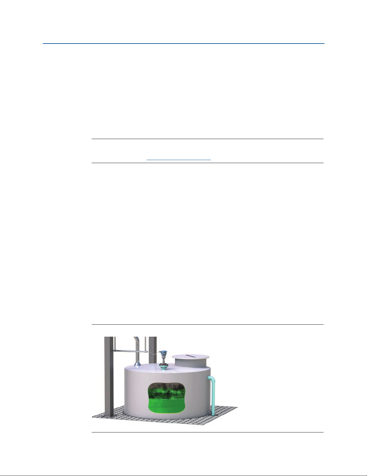
When the level detector is used as a used as a high level alarm or for overfill detection
(Figure 1-1), the liquid medium rises in the tank or pipe, making contact with the fork which
then causes the electronics to indicate a wet condition.
®
The wet and dry conditions can be transmitted digitally as a HART
output using the analog output. See “Analog output type and operating modes” on
page 23 for details.
Figure 1-1. Typical Application
signal or as a discrete
Introduction
1
Page 12

Introduction
January 2017
Reference Manual
00809-0100-4140, Rev AA
Major components of the point level detector are the fork and the electronics housing.
The electronics housing contains the output electronics board, optional external
configuration buttons, and terminal block.
An optional Local Operator Interface (“LOI”) uses a character display (Figure 1-2) to indicate
the live output state, diagnostic messages, and menus. There are two rows of characters,
with 8 on the upper row and 6 on the lower row. The LOI also comes with two integral
buttons (“internal buttons”) for using the menu system.
Figure 1-2. Local Operator Interface (LOI) Display
1.3 Using this manual
The sections in this manual provide information on installing, operating, and maintaining
the Rosemount 2140 and Rosemount 2140:SIS Level Detectors (“level detectors”).
The sections are organized as follows:
Section 2: Configuration provides instruction on basic and advanced configuration tasks
when commissioning and operating the level detectors.
Section 3: Hardware Installation contains mechanical installation instructions.
Section 4: Electrical Installation contains electrical installation instructions.
Section 5: Operation and Maintenance provides information on calibrating and testing.
Section 6: Troubleshooting provides troubleshooting techniques for common operating
problems.
Appendix A: Specifications and Reference Data contains specifications, dimension
drawings, and ordering information.
Appendix B: Product Certifications contains intrinsic safety approval information.
Appendix C: Field Communicator Menu Tree provides full menu trees to assist with
commissioning, operating, and maintenance tasks.
Appendix D: Local Operator Interface provides detailed LOI menu trees to assist with
commissioning, operating, and maintenance tasks.
2
Introduction
Page 13

Reference Manual
00809-0100-4140, Rev AA
1.4 Product recycling/disposal
Recycling of equipment and packaging should be taken into consideration and disposed of
in accordance with local and national legislation/regulations.
Introduction
January 2017
Introduction
3
Page 14

Introduction
January 2017
Reference Manual
00809-0100-4140, Rev AA
4
Introduction
Page 15

Reference Manual
00809-0100-4140, Rev AA
Section 2 Configuration
2.1 Safety messages
Procedures and instructions in this section may require special precautions to ensure the
safety of the personnel performing the operations. Information that raises potential safety
issues is indicated by a warning symbol ( ). Refer to the following safety messages before
performing an operation preceded by this symbol.
Explosions could result in death or serious injury.
Installation of this Rosemount 2140 and Rosemount 2140:SIS Level Detectors (“level
detectors”) in an explosive environment must be in accordance with the appropriate
local, national, and international standards, codes, and practices.
Please review Appendix B: Product Certifications for any restrictions associated with a
safe installation.
Before connecting a Field Communicator in an explosive atmosphere, ensure the
instruments in the loop are installed in accordance with intrinsically safe or
non-incendive field wiring practices.
In an explosion-proof/flameproof installation, do not remove the level detector covers
when power is applied to the unit.
Process leaks may cause harm or result in death.
Install and tighten process connectors before applying pressure.
Electrical shock can result in death or serious injury.
Avoid contact with the leads and terminals. High voltage that may be present on leads
can cause electrical shock.
Configuration
January 2017
2.2 Overview
This section provides instructions for using a Field Communicator, AMSTM Device Manager,
or Local Operator Interface (LOI) to configure the Rosemount 2140 or Rosemount 2140:SIS
Level Detectors.
For convenience, Field Communicator fast key sequences are labeled “Fast keys”.
Full Field Communicator menu trees are in Appendix C: Field Communicator Menu Tree.
Local Operator Interface menu trees are in Appendix D: Local Operator Interface.
Configuration
5
Page 16

Configuration
January 2017
2.3 Get started with your preferred configuration tool
The Rosemount 2140 Level Detector and Rosemount 2140:SIS Level Detector can easily be
configured by using:
Device Description (DD) based systems
e.g. AMS Device Manager and the 475 Field Communicator
Local Operator Interface (LOI)
2.3.1 AMS Device Manager
Get the latest Device Description (DD)
The Device Description (DD) is a configuration tool that is developed to assist the user
through the configuration tasks. The Rosemount 2140 DD is typically installed together
with AMS Device Manager.
To download the latest HART DD, visit the Emerson Process Management Device Install Kit
site at Emerson.com/devicefiles
Reference Manual
00809-0100-4140, Rev AA
After downloading, add the DD to AMS Device Manager:
1. Close AMS Device Manager.
2. Click the Start button, and then select All Programs > AMS Device Manager >
Add Device Type.
3. Browse to the downloaded DD files and select OK.
In the Add Device Type application, select the Help button for more information on how to
complete this operation.
Configure the HART® modem interface
Before connecting to the device using a HART modem, the HART modem interface must be
configured in AMS Device Manager:
1. Close AMS Device Manager.
2. Click the Start button, and then select All Programs > AMS Device Manager >
Network Configuration.
3. Select Add.
4. In the drop down list, select HART modem and select Install.
5. Follow the on-screen instructions.
In the Network Configuration application, select the Help button for more information on
how to complete this operation.
6
Configuration
Page 17

Reference Manual
A
B
C
D
E
F
G
00809-0100-4140, Rev AA
2.3.2 Field Communicator
An overview of the Field Communicator is shown in Figure 2-1.
See “Field Communicator menu trees” on page 125 for the menu tree diagrams.
Figure 2-1. 475 Field Communicator
Configuration
January 2017
A. Power key E. Enter key
B. Navigation keys F. Function key
C. Tab key G. Alphanumeric keypad
D. Backlight key
Get the latest Device Description (DD)
If the Rosemount 2140 DD is not included in your 475, then use the Easy Upgrade Utility to
update the Field Communicator with the latest DD.
For more information on how to update the DD and all the capabilities, see the 475 Field
Communicator User’s Manual
, available at www.fieldcommunicator.com.
2.3.3 Local Operator Interface (LOI)
The LOI requires option code M4 to be ordered.
To activate the LOI, push either configuration button. Configuration buttons are located on
the LCD display (after removing the housing cover to access), or underneath the top tag of
the point level detector. See Table 2-1 for configuration button functionality and Figure 2-2
for configuration button location.
When using the LOI for configuration, several features require multiple screens for a
success ful con fig uratio n. Data entered w ill be saved on a screen-by-screen basis; the LOI will
indicate this by flashing “SAVED” on the LCD display each time.
Configuration
7
Page 18

Configuration
B
January 2017
Reference Manual
00809-0100-4140, Rev AA
LOI menu trees are available in Appendix D: Local Operator Interface.
Figure 2-2. LOI Configuration Buttons
A
A. Internal configuration buttons
B. External configuration buttons
Table 2-1. LOI Button Operation
Button
Left No (SCROLL
Right Yes (ENTER
2.4 Switching HART Revision
2.4.1 Switching HART revision with a generic menu
If the HART configuration tool is not capable of communicating with a HART Revision 7
device, it should load a generic menu with limited capability. The following procedures
allow for switching between HART Revision 7 and HART Revision 5 from a generic menu.
1. Locate “Message” field.
a. To change to HART Revision 5, enter HART5 and 27 spaces in the message field.
b. To change to HART Revision 7, Enter: HART7 and 27 spaces in the message field.
8
Configuration
Page 19

Reference Manual
00809-0100-4140, Rev AA
Configuration
January 2017
2.4.2 Switching HART revision with Field Communicator
Fast keys
1. From the Home screen, select 2: Configure.
2. Select 2: Manual Setup > 5: HART (or 6: HART if Scaled Variable is available).
3. Select 2: Communication Settings > 4: Change HART Revision.
4. Change the HART revision.
Note
When messages about the loop appear, take appropriate safe action and select “OK”.
See “Configuration basics” on page 10 for further information.
2, 2, 5 [or 6], 2, 4
2.4.3 Switching HART Revision with AMS Device Manager
1. Click on Manual Setup, and then select the HART tab.
2. Select Change HART Revision and then follow the on screen prompts.
Note
AMS Device Manager versions 10.5 or greater are compatible with HART Revision 7.
Note
When messages about the loop appear, take appropriate safe action and select “Next >”.
See “Configuration basics” on page 10 for further information.
2.4.4 Switching HART revision with Local Operator Interface
1. Press any LOI button to activate the menu.
(See Table 2-1 on page 8 for assistance with using the LOI buttons).
2. Scroll down (
3. Scroll down (
4. To change HART revision:
a. Select HART REV 5 () or scroll down (
5. Exit the menu system by either waiting one minute for the EXIT MENU? prompt, or
scrolling down menus to find and select BACK TO MENU and EXIT MENU.
Note
When messages about the loop appear, take appropriate safe action and select “”.
See “Configuration basics” on page 10 for further information.
) and then select EXTENDED MENU ().
) and then select HART REV().
) and select HART REV 7() to switch.
Configuration
9
Page 20

Configuration
January 2017
2.5 Configuration basics
The Rosemount 2140 and 2140:SIS Level Detectors (“level detectors”) can be configured
before or after installation. Configuring the point level detector before installation ensures
all level detector components are in working order before installation.
2.5.1 Setting the security switch
Verify that the security switch is set in the unlock position ( ) to proceed with
configuration. See Figure 2-6 on page 43 for the switch location.
2.5.2 Setting the loop to manual
When sending or requesting data that would disrupt the loop or change the point level
detector output, set the process application loop to manual control. The Field
Communicator, AMS Device Manager, or the LOI prompts you to set the loop to manual
when necessary. The prompt is only a reminder. Acknowledging this prompt does not set
the loop to manual. It is necessary to set the loop to manual control as a separate operation.
Reference Manual
00809-0100-4140, Rev AA
2.6 Configure device using Guided Setup
The options available in the Guided Setup wizard include all items required for basic
operation. All basic configuration parameters are described in “Basic setup” on page 14.
2.6.1 Guided setup on the AMS Device Manager
1. Click the Start button, and then select All Programs > AMS Device Manager >
AMS Device Manager.
2. Select View > Device Connection View.
3. In the Device Connection View, double-click the HART modem icon.
4. Double-click the device icon.
5. From the Home screen, select Configure > Guided Setup.
6. Select Basic Setup and follow the on-screen instructions.
2.6.2 Guided setup on the Field Communicator
1. Turn on the Field Communicator.
10
2. From the Main Menu, tap the HART symbol. The Field Communicator now
connects to the device.
3. From the Home screen, select Configure > Guided Setup.
4. Select Basic Setup and follow the on-screen instructions.
Configuration
Page 21

Reference Manual
00809-0100-4140, Rev AA
Configuration
January 2017
2.6.3 Guided setup on the LOI
The Guided Setup wizard is not available on the LOI. Turn to “Basic setup” on page 14 for the
LOI instructions to configure basic parameters, and then return here to verify configuration.
2.7 Verify the configuration before installation
It is recommended that various configuration parameters are verified prior to installation
into the process. The various parameters are detailed out for each configuration tool.
2.7.1 Verifying configuration (Field Communicator or AMS)
Configuration parameters, listed in Table 2-2, are to be reviewed before the level detector is
installed. From the HOME screen of the Field Communicator, enter the fast key sequences
listed. Alternatively, turn to the page for detailed instructions.
Table 2-2. Verifying Configuration (Fast Key Sequences)
Fast key sequence
Parameter
Tag 1, 8, 1, 2 1,8, 1, 1
Model 1, 8, 1, 3 1,8, 1, 3
Primary Variable (page 11) 3, 2, 1, 1 3, 2, 1, 1
Sensor Operating Mode (page 14) 2, 2, 1, 1, 1 2, 2, 1, 1, 1
Sensor Output Delay (page 16) 2, 2, 1, 1, 2 2, 2, 1, 1, 2
Media Density (page 17) 2, 2, 1, 1, 3 2, 2, 1, 1, 3
Sensor Fault Delay (page 22) 2, 2, 1, 3, 2 2, 2, 1, 3, 2
Current Output Type
Custom Off Current
Custom On Current
Upper Range Value
Lower Range Value
High Alarm Level
Low Alarm Level
High Saturation Level
Low Saturation Level
Alarm Switch Position/Direction (page 46) 2, 2, 2, 5, 2 2, 2, 2, 5, 2
1. Only applicable when the Primary Variable is mapped to the Output State variable.
2. Only applicable when Current Output Type is set to “Custom”.
3. Only applicable when the Primary Variable is mapped to the Sensor Frequency or Scaled Variable variables.
See “Dynamic variables configuration” on page 13 and “Analog output range points” on page 26 for details.
4. Alarm level and saturation level indicated depends on the setting of alarm level switch (page 46) and the ordered Alarm
Level code (Table A-6 on page 115).
(1)
(page 23)
(2)
(page 23)
(2)
(page 23) 2, 2, 2, 1, 4 2, 2, 2, 1, 4
(3)
(page 26)
(3)
(page 26) 2, 2, 2, 2, 3 2, 2, 2, 2, 3
(4)
(page 33)
(4)
(page 33) 2, 2, 2, 5, 6 2, 2, 2, 5, 6
(3)(4)
(page 33) 2, 2, 2, 5, 4 2, 2, 2, 5, 4
(3)(4)
(page 33) 2, 2, 2, 5, 5 2, 2, 2, 5, 5
HART 7 HART 5
2, 2, 2, 1, 1 2, 2, 2, 1, 1
2, 2, 2, 1, 3 2, 2, 2, 1, 3
2, 2, 2, 2, 2 2, 2, 2, 2, 2
2, 2, 2, 5, 3 2, 2, 2, 5, 3
Configuration
11
Page 22

Configuration
January 2017
2.7.2 Verifying configuration (LOI)
1. Press any configuration button to activate the LOI.
2. Select VIEW CONFIG ().
Reference Manual
00809-0100-4140, Rev AA
3. Scroll down (
TAG
MODEL – e.g. “2140”.
T Range – Operating temperature range (page 115)
EFP – Extended Features Package enabled (Yes/No)
(1)
IS PV
(1)
S UNIT
(2)
T UNIT
OP MODE – Operating mode (page 14).
DENSITY – Media density (page 17).
O DLY – Sensor output delay (page 16).
F DLY – Fault output delay (page 22).
AOMODE
OFF MA
ON MA
S-START – Device test (page 73)/proof test (page 75) at start.
URV
LRV
DAMPING
HIALRM
LOALRM
HI SAT
LO SAT
(3)
(4)
(4)
(5)
(5)
(1)
(6)
(6)
(5)(6)
(5)(6)
) to review the following parameters prior to installation:
– Primary Variable mapping (page 11)
– Secondary Variable units (page 129)
– Electronics temperature units (page 30)
– Analog Output operating mode (page 23)
– Custom mA output for ‘off’ output state (page 23)
– Custom mA output for ‘on’ output state (page 23)
– Upper range value for analog output (page 26)
– Lower range value for analog output (page 26)
– Scaled Variable damping (page 28)
– High alarm level (page 33)
– Low alarm level (page 33)
– High saturation level (page 33)
– Low saturation level (page 33)
12
ALARM – Alarm switch position/direction (page 46)
SECURE – Security switch position (page 43)
1. Only available when the Extended Features Package (EFP) is enabled.
2. SI units only.
3. Only visible when the Primary Variable (“PV”) is mapped to the Output State variable.
4. Only visible when the Analog Output operating mode is set to custom.
5. Only visible when the Primary Variable (“PV”) is mapped to the Sensor Frequency or Scaled Variable variables.
6. Alarm level and saturation level indicated depends on the setting of hardware alarm level switch (page 46)
and the ordered Alarm Level code (Table A-6 on page 115).
4. Exit the menu system by either waiting one minute for the EXIT MENU? prompt, or
scrolling down menus to find and select BACK TO MENU and EXIT MENU.
Configuration
Page 23

Reference Manual
00809-0100-4140, Rev AA
2.7.3 Dynamic variables configuration
This section describes how to verify that the four dynamic variables are mapped correctly.
If incorrectly mapped, see “HART (re-mapping dynamic variables)” on page 31.
Default mapped dynamic variables
By default, the four mapped dynamic variables are:
Primary Variable (“PV”)
Mapped to: Output State – the level detector output state is off (0.0) or on (1.0).
Secondary Variable (“SV”)
Mapped to: Sensor State – indicates the state of the sensor as dry (0.0) or wet (1.0).
Tertiary Variable (“TV”)
Mapped to: Sensor Frequency – the frequency of the vibrating fork in units of Hz.
Quaternary Variable (“QV”)
Mapped to: Electronics Temperature – the temperature inside the housing in °F/°C.
Configuration
January 2017
Verifying dynamic variables (Field Communicator)
Fast keys
To view the Variables menu:
1. From the Home screen, select 3: Service Tools.
2. Select 2: Variables > 2: Mapped Variables
3. Select a dynamic variable:
a. Select 1: Primary Variable.
b. Select 2: Secondary Variable.
c. Select 3: Tertiary Variable.
d. Select 4: Quaternary Variable.
3, 2, 2
Verifying dynamic variables (AMS Device Manager)
1. Right click on the device and select Overview from the menu.
2. Click the Mapped Variables button to display the primary, secondary, tertiary, and
quaternary variables.
Verifying dynamic variables (LOI)
Configuration
The mapping of dynamic variables is not viewable on the LOI.
13
Page 24

Configuration
January 2017
Reference Manual
00809-0100-4140, Rev AA
Optional re-mapping of PV
Versions of the Rosemount 2140 with the Extended Features Package (EFP)
can re-map the PV to:
Sensor Frequency
Scaled Variable
Optional re-mapping of SV, TV, or QV
The Rosemount 2140 and Rosemount 2140:SIS can re-map the SV, TV, or QV to:
Output State
Sensor State
Sensor Frequency
Electronics Temperature
Terminal Voltage
Versions of the Rosemount 2140 with the Extended Features Package (EFP)
can also re-map the SV, TV, or QV to:
Scaled Variable
Note
See “HART (re-mapping dynamic variables)” on page 31 for related information.
2.8 Basic setup
2.8.1 Sensor operation mode
Fast keys
The level detector has three operation modes:
Normal (Rosemount 2140 only)
Default mode with no sensor fault detection enabled.
Enhanced wet
Optional mode where the Sensor State device variable is forced to a ‘wet state’
while sensor faults are detected. (Default mode on Rosemount 2140:SIS).
Enhanced dry
Optional mode where the Sensor State device variable is forced to a ‘dry state’
while sensor faults are detected.
2, 2, 1, 1, 1
14
Note
Sensor State (page 82) is used to derive the Output State (page 13).
Configuration
Page 25

Reference Manual
00809-0100-4140, Rev AA
To change or view the mode (Field Communicator)
1. From the Home screen, select 2: Configure.
2. Select 2: Manual Setup > 1: Operation > 1: Application.
3. Select 1: Sensor Operation Mode.
4. If changing the mode setting:
a. Select a mode: “Normal”, “Enhanced (Fault=Wet)”, or “Enhanced (Fault=Dry)”.
Note
When messages about the loop appear, take appropriate safe action and select “OK”.
See “Configuration basics” on page 10 for further information.
To change or view the mode (AMS Device Manager)
1. Right click on the device and select Configure.
Configuration
January 2017
2. Select Manual Setup, and then select the Operation tab.
3. If changing the mode setting:
a. Select a mode: “Normal”, “Enhanced (Fault=Wet)”, or “Enhanced (Fault=Dry)” at
the Sensor Operation Mode field.
Note
When messages about the loop appear, take appropriate safe action and select “Next >”.
See “Configuration basics” on page 10 for further information.
To change or view the mode (LOI)
1. Press any LOI button to activate the menu.
(See Table 2-1 on page 8 for assistance with using the LOI buttons).
2. If changing the mode setting:
a. Scroll down (
b. Scroll down (
c. Select SENSOR OPMODE ().
d. Follow on-screen instructions to select a new mode:
NORM (normal), EN WET (enhanced wet), or EN DRY (enhanced dry).
) and then select EXTENDED MENU ().
) and then select SENSOR ().
Configuration
3. If viewing the mode setting:
a. Select VIEW CONFIG ().
b. Scroll down (
4. Exit the menu system by either waiting one minute for the EXIT MENU? prompt, or
scrolling down menus to find and select BACK TO MENU and EXIT MENU.
) until OPMODE and the mode setting appears.
15
Page 26

Configuration
January 2017
Note
When messages about the loop appear, take appropriate safe action and select “”.
See “Configuration basics” on page 10 for further information.
2.8.2 Sensor output delay
Reference Manual
00809-0100-4140, Rev AA
Fast keys
When there is a detected change in process conditions, from wet-to-dry or
dry-to-wet, the Sensor Output Delay variable can action a delay of up to 3600 seconds
before the new state change is indicated. The default delay is one second.
Depending on the application, a suitable delay can prevent constant switching of the
output state. If, for example, there are waves in a tank, then there may be splashes causing
intermittently detected changes in process conditions. The sensor output delay ensures
that the fork is dry or wet for a suitable period before switching.
2, 2, 1, 1, 2
To change or view the delay setting (Field Communicator)
1. From the Home screen, select 2: Configure.
2. Select 2: Manual Setup > 1: Operation > 1: Application.
3. Select 2: Sensor Output Delay.
4. If changing the delay setting:
a. Edit a delay value in the range 0 to 3600 seconds.
Note
When messages about the loop appear, take appropriate safe action and select “OK”.
See “Configuration basics” on page 10 for further information.
16
To change or view the delay setting (AMS Device Manager)
1. Right click on the device and select Configure.
2. Select Manual Setup, and then the select the Operation tab.
3. If changing the delay setting:
a. Edit a delay in the range 0 to 3600 seconds at the Sensor Output Delay field.
To change or view the delay setting (LOI)
1. Press any LOI button to activate the menu.
(See Table 2-1 on page 8 for assistance with using the LOI buttons).
2. If changing the mode setting:
a. Scroll down (
b. Scroll down (
) and then select EXTENDED MENU ().
) and then select SENSOR ().
Configuration
Page 27

Reference Manual
00809-0100-4140, Rev AA
c. Scroll down () and then select OUTPUT DELAY ().
d. Follow on-screen instructions and edit a new delay setting in the range 0 to 3600.
Entering a delay outside this range results in ERROR being displayed.
3. If viewing the mode setting:
a. Select VIEW CONFIG ().
b. Scroll down (
4. Exit the menu system by either waiting one minute for the EXIT MENU? prompt, or
scrolling down menus to find and select BACK TO MENU and EXIT MENU.
Note
When messages about the loop appear, take appropriate safe action and select “”.
See “Configuration basics” on page 10 for further information.
2.8.3 Media density
Configuration
January 2017
) until O DELAY and the delay setting appears.
Fast keys
2, 2, 1, 1, 3
The measured frequency of the fork, when immersed in process medium, can be affected
by liquid density variations. As a result, the dry-to-wet and wet-to-dry switching points are
different for all types and varieties of process medium (Figure 2-3 on page 18).
To overcome this, accurate switching points can be calculated by the Rosemount 2140 and
Rosemount 2140:SIS after a suitable density band is selected for the process medium.
Media Density options the Rosemount 2140 and Rosemount 2140:SIS are:
0.4 – 0.6 SG (for a 400 to 600 kg/m
0.5 – 0.9 SG (for a 500 to 900 kg/m
0.8 – 1.3 SG (for a 800 to 1300 kg/m
1.2 – 3.0 SG (for a 1200 to 3000 kg/m
3
range – e.g. propane)
3
range – e.g. alcohol)
3
range – e.g. water) (default selection)
3
range – e.g. acid)
Extra options on the Rosemount 2140 are:
Low compacted sediment
Medium compacted sediment
High compacted sediment
Extreme compacted sediment
Configuration
Note
Versions of the Rosemount 2140 and Rosemount 2140:SIS with the Extended Features
Package (EFP) can use Media Learn (page 19) to automatically select a density band.
For all other versions, keep the default setting for Media Density when the liquid specific
gravity is unknown.
17
Page 28

Configuration
Liquid Density (SG)
00.5
1.0
1.5
2.0
2.5 3.0
Switch Frequency
A
B
C
D
January 2017
Reference Manual
00809-0100-4140, Rev AA
Figure 2-3. Example of Calculated Switching Points for a Process Media
A. Top limit boundary (allowing for variations in fork manufacture).
B. Nominal switching point frequencies for this process medium.
C. Bottom limit boundary (allowing for variations in fork manufacture).
D. Dry fork frequency – see “Dry fork frequency and switching points” on page 85 for details.
To change or view the media density (Field Communicator)
1. From the Home screen, select 2: Configure.
2. Select 2: Manual Setup > 1: Operation > 1: Application.
3. Select 3: Media Density.
4. Select the option that is closest to the process medium density range.
Note
When messages about the loop appear, take appropriate safe action and select “OK”.
See “Configuration basics” on page 10 for further information.
To change or view the media density (AMS Device Manager)
1. Right click on the device and select Configure.
2. Select Manual Setup, and then select the Operation tab.
3. Select the Media Density option that is closest to the process medium density
range.
Note
When messages about the loop appear, take appropriate safe action and select “Next >”.
See “Configuration basics” on page 10 for further information.
18
Configuration
Page 29
Reference Manual
OK
Tines Fully
Immersed
00809-0100-4140, Rev AA
To change or view the media density (LOI)
1. Press any LOI button to activate the menu.
Configuration
January 2017
(See Table 2-1 on page 8 for assistance with using the LOI buttons).
2. Scroll down (
3. Scroll down (
4. Select DENSITY ().
5. Follow on-screen instructions to select an option that is closest to the process
medium density range.
Note
When messages about the loop appear, take appropriate safe action and select “”.
See “Configuration basics” on page 10 for further information.
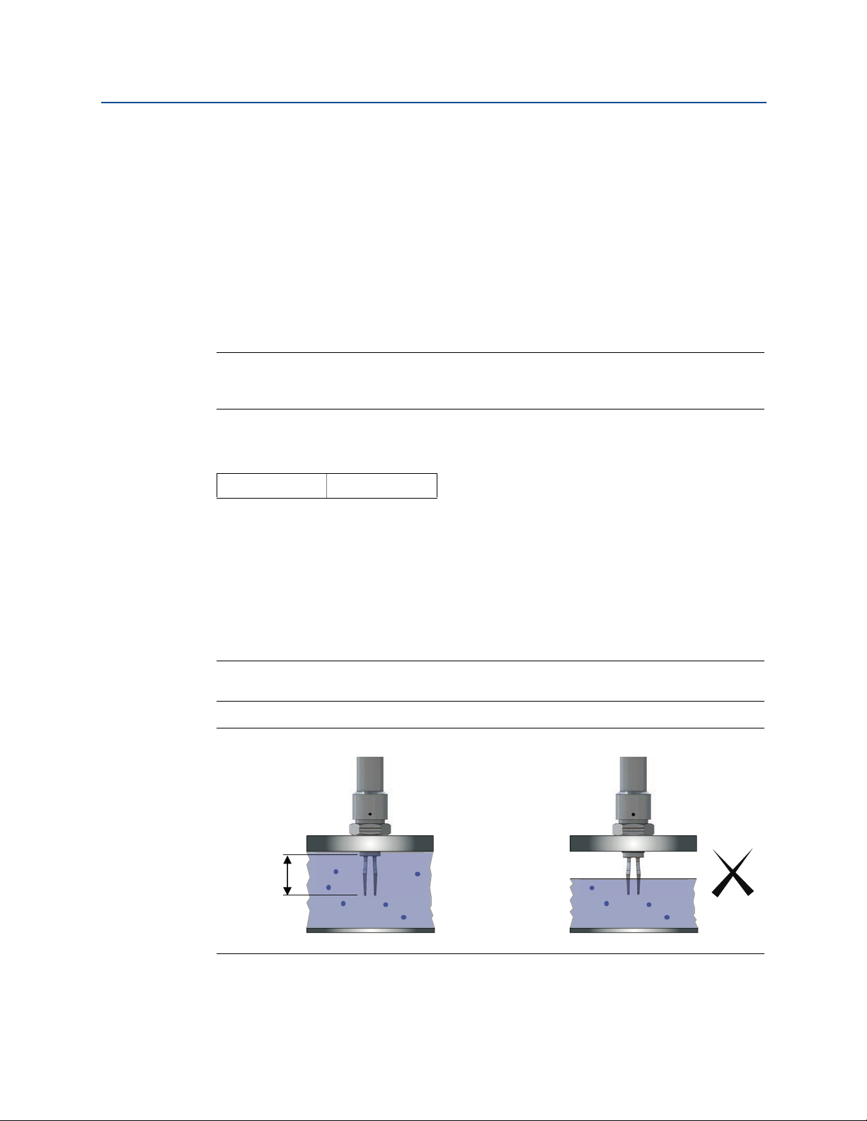
2.8.4 Media learn
Fast keys
Versions of the Rosemount 2140 and Rosemount 2140:SIS with the Extended Features
Package (EFP) can use the Media Learn function.
Media Learn makes configuring the Media Density variable (page 17) even easier.
This procedure requires the fork tines to be fully immersed in the process medium for a
short period to gather the frequency data, calculate the liquid density, and then auto-select
the option for the Media Density variable.
) and then select EXTENDED MENU ().
) and then select MEDIA ().
2, 2, 1, 1, 5
Configuration
Note
Media Learn may have unexpected results in high temperatures.
Figure 2-4. Fully Immersed Tines for Media Learn
19
Page 30

Configuration
January 2017
Reference Manual
00809-0100-4140, Rev AA
To use Media Learn (Field Communicator)
1. From the Home screen, select 2: Configure.
2. Select 2: Manual Setup > 1: Operation > 1: Application.
3. Select 5: Media Learn.
4. Follow on-screen instructions until the learning procedure is completed.
Note
When messages about the loop appear, take appropriate safe action and select “OK”.
See “Configuration basics” on page 10 for further information.
To use Media Learn (AMS Device Manager)
1. Right click on the device and select Configure.
2. Select Manual Setup, and then select the Operation tab.
3. Click on the Media Learn button (in the Application box).
4. Follow on-screen instructions until the learning procedure is completed.
(The “Recall Learnt” option restores a previously learnt media density).
5. In the Application box, the Learnt box is now marked.
Note
When messages about the loop appear, take appropriate safe action and select “Next >”.
See “Configuration basics” on page 10 for further information.
To use Media Learn (LOI)
1. Press any LOI button to activate the menu.
(See Table 2-1 on page 8 for assistance with using the LOI buttons).
2. Scroll down (
3. Scroll down (
4. Scroll down (
5. Follow on-screen instructions until the learning procedure is completed.
) and select EXTENDED MENU ().
) and select MEDIA ().
) and select LEARN ().
20
Note
When messages about the loop appear, take appropriate safe action and select “”.
See “Configuration basics” on page 10 for further information.
Configuration
Page 31

Reference Manual
00809-0100-4140, Rev AA
2.8.5 Allowable change in dry fork frequency
Configuration
January 2017
Fast keys
When the level detector is re-calibrated in the field, a comparison is made between the new
dry fork frequency and original factory-set Dry Fork Frequency value. If the difference is
greater than the allowable change value, the re-calibration is rejected. Check the fork for
damage, corrosion, or coating, and clean the fork if necessary before re-trying.
The default setting is 100 Hz, but can be set to a value in the range 0 to 255 Hz.
Setting the value to 0 Hz switches off the allowable change monitoring.
Note
Fast key sequence is 3, 4, 1, 2, 1 for the original factory-set Dry Fork Frequency.
2, 2, 1, 3, 1
To change or view the allowable change
(Field Communicator)
1. From the Home screen, select 2: Configure.
2. Select 2: Manual Setup > 1: Operation > 3: Sensor.
3. Select 1: Allowable Change In Dry Fork Frequency.
4. Follow the on-screen instructions to configure the allowable change.
Note
When messages about the loop appear, take appropriate safe action and select “OK”.
See “Configuration basics” on page 10 for further information.
To change or view the allowable change
(AMS Device Manager)
1. Right click on the device and select Configure.
2. Select Manual Setup, and then select the Operation tab.
3. If changing the allowable change setting:
a. Edit a frequency in the range 0 to 255 Hz at the Allowable Change In Dry Fork
Frequency field.
Note
When messages about the loop appear, take appropriate safe action and select “Next >”.
See “Configuration basics” on page 10 for further information.
To change or view the allowable change (LOI)
This configuration parameter is not available on the LOI.
Configuration
21
Page 32

Configuration
January 2017
2.8.6 Sensor fault delay
Reference Manual
00809-0100-4140, Rev AA
Fast keys
When the level detector is operating in Enhanced Mode and detects a fork sensor fault,
Sensor State (page 82) indicates a fault state after a delay.
The default setting is 5 seconds. It can be set to a value in the range 0 to 3600 seconds.
Note
When the Rosemount 2140 is operating in Normal mode, a fork sensor fault is not detected
and Sensor State continues to indicate a valid state.
2, 2, 1, 3, 2
To change or view the sensor fault delay
(Field Communicator)
1. From the Home screen, select 2: Configure.
2. Select 2: Manual Setup > 1: Operation > 3: Sensor.
3. Select 2: Sensor Fault Delay.
4. Follow the on-screen instructions to configure the delay.
Note
When messages about the loop appear, take appropriate safe action and select “OK”.
See “Configuration basics” on page 10 for further information.
To change or view the sensor fault delay
(AMS Device Manager)
1. Right click on the device and select Configure.
2. Select Manual Setup, and then select the Operation tab.
3. If changing the delay setting:
a. Edit the number of seconds at the Sensor Fault Delay field.
Note
When messages about the loop appear, take appropriate safe action and select “Next >”.
See “Configuration basics” on page 10 for further information.
To change or view the sensor fault delay (LOI)
1. Press any LOI button to activate the menu.
(See Table 2-1 on page 8 for assistance with using the LOI buttons).
2. If changing the mode setting:
a. Scroll down (
b. Scroll down (
) and then select EXTENDED MENU ().
) and then select SENSOR ().
22
Configuration
Page 33

Reference Manual
00809-0100-4140, Rev AA
c. Scroll down () and then select FAULT DELAY ().
d. Follow on-screen instructions and edit a new delay setting in the range 0 to 3600.
Entering a delay outside this range results in ERROR being displayed.
3. If viewing the mode setting:
a. Select VIEW CONFIG ().
b. Scroll down (
) until F DELAY and the delay setting appears.
4. Exit the menu system by either waiting one minute for the EXIT MENU? prompt, or
scrolling down menus to find and select BACK TO MENU and EXIT MENU.
Note
When messages about the loop appear, take appropriate safe action and select “”.
See “Configuration basics” on page 10 for further information.
2.8.7 Analog output type and operating modes
The analog output is driven by a device variable mapped to the Primary Variable (“PV”).
Carefully read displayed warnings that appear before applying changes.
Configuration
January 2017
This sub-section is for establishing how the analog output will operate.
Current output type
Fast keys
Options to select are:
4 and 20 mA – i.e. 4mA = ‘off’ and 20 mA = ‘on’ switched output states.
Continue reading this sub-section for related configuration steps.
8 and 16 mA – i.e. 8 mA = ‘off’ and 16 mA = ‘on’ switched output states.
Continue reading this sub-section for related configuration steps.
Custom– i.e. user-set output currents for ‘off’/‘on’ switched output states.
The output current levels for ‘off’ and ‘on’ output states are user-entered under the
Custom Off Current and Custom On Current variables. Continue reading this
sub-section for related configuration steps.
LEVELTESTER– compatibility mode
See Table 2-3 for output current information.
Table 2-3. LEVELTESTER Output Current
Output current Wet on Dry on
2, 2, 2, 1, 1
Configuration
Wet 18.5±0.5 mA @ 0.5 Hz 6 mA
Dry 9 mA 13.5±0.5 mA @ 0.5 Hz
23
Page 34

Configuration
January 2017
Reference Manual
00809-0100-4140, Rev AA
Current output operating mode
Fast keys
2, 2, 2, 1, 2
This selects the fork sensor state associated with the Output State device variable
indicating ‘on’. Options to select are:
Dry on
Wet on
Custom “off” current
Fast keys
When the Current Output Type is set to “Custom”, this parameter is for entering the
output current to be applied when:
The Current Output Operating Mode variable is set to “Dry on”
and the fork is immersed in liquid or sand/sediment.
The Current Output Operating Mode variable is set to “Wet on”
and the fork is not immersed in liquid or sand/sediment.
2, 2, 2, 1, 3
Custom “on” current
Fast keys
2, 2, 2, 1, 4
When the Current Output Type is set to “Custom”, this parameter is for entering the
output current to be applied when:
The Current Output Operating Mode variable is set to “Wet on”
and the fork is immersed in liquid or sand/sediment.
The Current Output Operating Mode variable is set to “Dry on”
and the fork is not immersed in liquid or sand/sediment.
To change current output type and operating mode
(Field Communicator
1. From the Home screen, select 2: Configure.
2. Select 2: Manual Setup > 2: Analog Output > 1: Mode Setup.
3. If changing the current output type:
a. Select 1: Current Output Type.
b. Make the type selection.
c. If the type is set to Custom, enter output current levels in the
3: Custom Off Current and 4: Custom On Current screens.
4. If changing the current output operating mode:
a. Select 2: Current Output Operating Mode.
b. Make the mode selection.
)
24
Configuration
Page 35

Reference Manual
00809-0100-4140, Rev AA
Note
When messages about the loop appear, take appropriate safe action and select “OK”.
See “Configuration basics” on page 10 for further information.
To change the current output type and operating mode
(AMS Device Manager)
1. Right click on the device and select Configure.
2. Select Manual Setup, and then select the Analog Output tab.
3. If changing the current output type:
a. Select an option for the Current Output Type field.
b. If the type selected is Custom, enter output currents for ‘off’/‘on’ output states at
4. If changing the current output operating mode:
a. Select an option for the Current Output Operating Mode field.
Configuration
January 2017
the Custom Off Current and Custom On Current fields.
5. Click on Send.
6. Carefully read the warning and click Yes if it is safe to apply the changes.
Note
When messages about the loop appear, take appropriate safe action.
See “Configuration basics” on page 10 for further information.
To change the current output type and operating mode (LOI)
1. Press any LOI button to activate the menu.
(See Table 2-1 on page 8 for assistance with using the LOI buttons).
2. If changing the current output type:
a. Scroll down (
b. Scroll down (
c. Scroll down (
d. Follow on-screen instructions and select a current output type
(“4 and 20 mA”, “8 and 16 mA”, or “Custom”).
e. If the type selected is “Custom”, enter output currents for ‘off’ and ‘on’ output
states at the CUSTOM OFF and CUSTOM ON menus.
3. If changing the current output operating mode:
) and then select EXTENDED MENU ().
) and then select ANALOG OUTPUT ().
) and then select OUTPUT TYPE ().
Configuration
a. Scroll down (
b. Scroll down (
c. Scroll down (
d. Follow on-screen instructions and select a current output operating mode
(“Wet on” or “Dry on”).
) and then select EXTENDED MENU ().
) and then select ANALOG OUTPUT ().
) and then select OPERATE MODE ().
25
Page 36

Configuration
January 2017
Note
When messages about the loop appear, take appropriate safe action and select “”.
See “Configuration basics” on page 10 for further information.
2.8.8 Analog output range points
The analog output is driven by a device variable mapped to the Primary Variable (“PV”).
Carefully read displayed warnings that appear before applying changes.
This section is for entering the range points for the PV to be output using the analog output.
The Lower Range Value (LRV) variable is the PV represented by 4 mA, and the Upper
Range Value (URV) variable is the PV represented by 20 mA. This PV range can be a sub-set
of the sensor limits defined by Upper PV Limit and Lower PV Limit variables (see Table 2-4
on page 28).
However, by default, the Output State is mapped to the PV. The range points for this are
read-only and identical to the associated sensor limits (see “Sensor limits” on page 28).
If supported, Sensor Frequency or Scaled Variable can instead be re-mapped to the PV.
The range points then automatically change from read-only to editable, allowing range
points to be changed, but are subject to the sensor limits (see “Sensor limits” on page 28).
Reference Manual
00809-0100-4140, Rev AA
Optionally, use Scaled Variable Damping (page 28) to smooth out large steps in output
current changes when the PV is a scaled variable.
See also “Site calibration of analog output” on page 70 for other related information.
Entering range points (Field Communicator)
Fast keys
1. From the Home screen, select 2: Configure.
2. Select 2: Manual Setup > 2: Analog Output > 2: Set Range Points.
3. Enter the PV value at 20 mA in the 2: Upper Range Value variable.
4. Enter the PV value at 4 mA in the 3: Lower Range Value variable.
Note
At the 4: Readings menu (2, 2, 2, 4), the 1: Analog Output item indicates the live output
current. The 2: Percent of Range item indicates the percentage of that output current in
terms of the complete 4–20 mA range. For example, 8 mA is 25% of range, 12 mA is 50%
Note
When messages about the loop appear, take appropriate safe action and select “OK”.
See “Configuration basics” on page 10 for further information.
2, 2, 2, 2
26
Configuration
Page 37

Reference Manual
00809-0100-4140, Rev AA
Entering range points (AMS Device Manager)
1. Right click on the device and select Configure.
2. Select Manual Setup, and then select the Analog Output tab.
3. Enter the PV at 4 mA in the Lower Range Value field.
4. Enter the PV at 20 mA in the Upper Range Value field.
5. Click Send.
6. Carefully read the warning and click Yes if it is safe to apply the changes.
Note
In the Readings box, the Analog Output device variable indicates the live output current.
The Percent of Range device variable indicates a percentage of th at output curren t in ter ms
of the complete 4–20 mA range. For example, 8 mA is 25% of range, 12 mA is 50%, etc.
Note
When messages about the loop appear, take appropriate safe action.
See “Configuration basics” on page 10 for further information.
Configuration
January 2017
Entering range points (LOI)
1. Press any LOI button to activate the menu.
(See Table 2-1 on page 8 for assistance with using the LOI buttons).
2. If changing the range points:
a. Scroll down (
b. Select ENTER VALUES ().
c. Select LRV ().
d. Follow on-screen instructions and edit a new PV value at 4 mA.
(Attempting to enter an invalid value results in ERROR being displayed).
e. Scroll down (
f. Follow on-screen instructions and edit a new PV value at 20 mA.
(Attempting to enter an invalid value results in ERROR being displayed).
3. If viewing the range points:
a. Select VIEW CONFIG ().
b. Scroll down (
c. Scroll down (
4. Exit the menu system by either waiting one minute for the EXIT MENU? prompt,
or scrolling down menus to find and select BACK TO MENU and EXIT MENU.
) and then select RERANGE ().
) and then select URV ().
) until LRV and the lower range value setting appears.
) until URV and the upper range value setting appears.
Configuration
Note
When messages about the loop appear, take appropriate safe action and select “”.
See “Configuration basics” on page 10 for further information.
27
Page 38

Configuration
January 2017
Reference Manual
00809-0100-4140, Rev AA
Sensor limits
Table 2-4 shows the sensor limits applied when a device variable is mapped to the PV
dynamic variable. They are used for scaling gauges in a Host system (e.g. AMS Device
Manager) and for validating the range points in the analog output (page 26).
Note
See also “Dynamic variables configuration” on page 13 for related information.
Table 2-4. Sensor Limits for Device Variables
Device Variables Lower PV Limit Upper PV Limit
Output State 0.0 1.0
Sensor State 0.0 1.0
Sensor Frequency 250.0 Hz 1800.0 Hz
Electronics Temperature –40 °C 85 °C
Terminal Voltage 10.5 V 42.4 V
Scaled Variable Defined by sensor frequency limits and scaling data.
2.8.9 Scaled Variable damping
Damping is an optional parameter for changing the response time of the level detector
when the PV is mapped to the Scaled Variable. Increasing the damping value can smooth
wide variations in the output caused by rapid input changes, but at the cost of decreasing
response times.
Damping settings range from 0.0 to 60.0 seconds. An appropriate damping setting is a
balance of the necessary response time, signal stability, and other requirements of the loop
dynamics within your system.
Carefully read displayed warnings that appear before applying changes.
Note
Versions of the Rosemount 2140 with the Extended Features Package (EFP) can re-map the
PV to Scaled Variable.
Damping with a Field Communicator
Fast keys
2, 2, 2, 2, 4
28
1. From the Home screen, select 2: Configure.
2. Select 2: Manual Setup > 2: Analog Output > 2: Set Range Points.
3. Select 4: Damping.
4. Enter the damping setting.
Configuration
Page 39

Reference Manual
00809-0100-4140, Rev AA
Note
When messages about the loop appear, take appropriate safe action.
See “Configuration basics” on page 10 for further information.
Damping with AMS Device Manager
1. Right click on the device and select Configure.
2. Select Manual Setup, and then select the Analog Output tab.
3. Enter the damping setting, and click Send.
4. Carefully read the warning and click Yes if it is safe to apply the changes.
Damping with a LOI
1. Press any LOI button to activate the menu.
2. If changing the damping setting:
Configuration
January 2017
(See Table 2-1 on page 8 for assistance with using the LOI buttons).
a. Scroll down (
b. Scroll down (
) and then select EXTENDED MENU ().
) and then select DAMPING ().
c. Follow on-screen instructions and edit a new damping setting in the range 0 to 60.
Attempting to enter a value outside this range results in ERROR being displayed.
If viewing the damping setting:
a. Select VIEW CONFIG ().
b. Scroll down (
) until DAMPING and the damping setting appears.
3. Exit the menu system by either waiting one minute for the EXIT MENU? prompt, or
scrolling down menus to find and select BACK TO MENU and EXIT TO MENU.
2.9 Local Operator Interface (LOI) display
Fast keys
The LOI display configuration allows customization of the displayed information to suit
application requirements. The LOI alternates between selected items.
Output State (page 13) Electronics Temperature (page 13)
Sensor State (page 13) Terminal Voltage (page 13)
Sensor Frequency (page 13) Percent of Range (page 26)
Scaled Variable
1. This is selectable only if the Rosemount 2140 has the Extended Features Package enabled.
(1)
2, 2, 2
(page 13)
Analog Output (page 26)
Configuration
Note
The LOI can also be configured to display configuration information during the device
startup. Select Review Parameters at Startup to enable this functionality.
29
Page 40

Configuration
January 2017
Reference Manual
00809-0100-4140, Rev AA
Configuring LOI display (using Field Communicator)
1. From the Home screen, select 2: Configure.
2. Select 2: Manual Setup > 5: Display.
3. For items 1 to 8, select or de-select the parameters to show on the LOI display.
Optionally, select 9: Review Parameters at Startup.
Configuring LOI display (using AMS Device Manager)
1. Right click on the device and select Configure.
2. Click Manual Setup, and then select the Display tab.
3. Select or de-select the parameters to show on the LOI display, and then click Send.
4. Optionally, select Review Parameters at Startup.
Configuring LOI display (using LOI)
1. Press any LOI button to activate the menu.
(See Table 2-1 on page 8 for assistance with using the LOI buttons).
2. Scroll down (
3. Scroll down (
a. Use the select () to change the setting to ON or OFF
b. Answer YES () to confirm the change or NO (
4. Exit the menu system by either waiting one minute for the EXIT MENU? prompt, or
scrolling down menus to find and select BACK TO MENU and EXIT TO MENU.
) and then select DISPLAY ().
), and then for each item:
2.9.1 Electronics temperature units
Note
Available on SI units only.
Changing temperature units (Field Communicator)
Fast keys
1. From the Home screen, select 2: Configure.
2, 2, 4, 3
) to abandon the change.
30
2. Select 2: Manual Setup > 4: Device Temperature > 3: Units.
3. Select the measurement units.
Note
When messages about the loop appear, take appropriate safe action and select “OK”.
See “Configuration basics” on page 10 for further information.
Configuration
Page 41

Reference Manual
00809-0100-4140, Rev AA
Changing temperature units (AMS Device Manager)
1. Right click on the device and select Configure.
2. Select Manual Setup, and then select the Device Temperature tab.
3. Select the measurement units at the Setup Unit box, and click Send.
Note
When messages about the loop appear, take appropriate safe action.
See “Configuration basics” on page 10 for further information.
Changing temperature units (LOI)
1. Press any LOI button to activate the menu.
Configuration
January 2017
(See Table 2-1 on page 8 for assistance with using the LOI buttons).
2. Scroll down (
3. Select DEG C or scroll down (
4. Exit the menu system by either waiting one minute for the EXIT MENU? prompt, or
scrolling down menus to find and select BACK TO MENU and EXIT MENU.
Note
When messages about the loop appear, take appropriate safe action and select “”.
See “Configuration basics” on page 10 for further information.
) and then select UNITS ().
) and select DEG F ().
2.10 Detailed setup
2.10.1 HART (re-mapping dynamic variables)
The re-mapping of process variables to the primary, secondary, tertiary, and quaternary
variables (“PV”, “SV”, “TV”, and “QV” respectively) can be performed here, if supported.
See “Dynamic variables configuration” on page 13 to find out what is supported.
The PV can be re-mapped with a Field Communicator, AMS Device Manager, or a LOI.
However, the other three variables (SV, TV, and QV) can only be re-mapped using a Field
Communicator or the AMS Device Manager.
Configuration
Note
The process variable assigned to the PV drives the analog output.
See “Analog output type and operating modes” on page 23 for further information.
31
Page 42

Configuration
January 2017
Reference Manual
00809-0100-4140, Rev AA
Re-mapping process variables (Field Communicator)
Fast keys
1. From the Home screen, select 2: Configure.
2. Select 2: Manual Setup > 5: (or 6:) HART.
3. Select 1: Variable Mapping.
4. Assign Primary Variable, Secondary Variable, Tertiary Variable and Quaternary
Variable to supported process variables.
Note
When messages about the loop appear, take appropriate safe action and select “OK”.
See “Configuration basics” on page 10 for further information.
2, 1, 5 (or 6), 1
Re-mapping process variables (AMS Device Manager)
1. Right click on the device and select Configure.
2. Select Manual Setup, and then click on the HART tab.
3. In the Variable Mapping box, assign Primary Variable, Secondary Variable,
Tertiary Variable and Quaternary Variable to supported process variables.
4. Click Send.
5. Carefully read the warning and click Yes if it is safe to apply the changes.
Note
When messages about the loop appear, take appropriate safe action.
See “Configuration basics” on page 10 for further information.
Re-mapping process variables (LOI)
1. Press any LOI button to activate the menu.
(See Table 2-1 on page 8 for assistance with using the LOI buttons).
2. Scroll down (
3. Scroll down (
4. Scroll down (
5. Exit the menu system by either waiting one minute for the EXIT MENU? prompt, or
scrolling down menus to find and select BACK TO MENU and EXIT TO MENU.
Note
When messages about the loop appear, take appropriate safe action and select “”.
See “Configuration basics” on page 10 for further information.
) and then select EXTENDED MENU ().
) and then select ASSIGN PV ().
) to the desired device variable mapping and then select () it.
32
Configuration
Page 43

Reference Manual
00809-0100-4140, Rev AA
2.10.2 Configuring alarm and saturation levels
Note
This function is available only when the Primary Variable (”PV”) is mapped to the Sensor
Frequency or Scaled Variable device variables.
The Rosemount 2140 continuously performs self-diagnostic routines. When there is a
device malfunction that is an alarm condition, the Analog Output current is driven to a
configured alarm level (see tables) based on the HI or LO alarm switch position (see “Setting
the alarm switch” on page 46) and the ordered Alarm Level code.
In normal operation, the Analog Output current is driven in response to fork frequency
changes. If the fork frequency goes outside sensor limits (see Table 2-4 on page 28), or if the
output current would be beyond the saturation points (see tables), the current is limited to
a saturation level based on the alarm switch position and the ordered Alarm Level code.
Table 2-5. Rosemount Alarm and Saturation Values (Alarm Level code C8)
Level 4–20 mA saturation 4–20 mA alarm
Configuration
January 2017
Low (LO position) 3.9 mA 3.75 mA
High (HI position) 20.8 mA
21.75 mA
Table 2-6. NAMUR-Compliant Alarm and Saturation Values (Alarm Level codes C4/C5)
Level 4–20 mA saturation 4–20 mA alarm
Low (LO position) 3.8 mA 3.6 mA
High (HI position) 20.5 mA
22.5 mA
Table 2-7. Custom Alarm and Saturation Values (Alarm Level code C1)
Level 4–20 mA saturation 4–20 mA alarm
Low (LO position) 3.7 mA to 3.9 mA 3.6 mA to 3.8 mA
High (HI position) 20.1 mA to 22.9 mA 20.2 mA -to 23.0 mA
Failure mode alarm and saturation levels can be custom-configured using a Field
Communicator, AMS Device Manager, or the Local Operator Interface (LOI).
The following limitations exist for custom-configurable levels:
Low alarm level must be less than the low saturation level.
High alarm level must be higher than the high saturation level.
Alarm and saturation levels must be separated by at least 0.1 mA.
Configuration
The configuration tool will provide an error message if the configuration rule is violated.
Note
When set to HART multi-drop mode, all saturation and alarm information is sent digitally;
saturation and alarm conditions will not affect the analog output.
See also “Establishing multi-drop communications (optional)” on page 40.
33
Page 44

Configuration
January 2017
Reference Manual
00809-0100-4140, Rev AA
To change or view alarm and saturation levels
(Field Communicator)
Fast keys
1. From the Home screen, select 2: Configure.
2. Select 2: Manual Setup > 2: Analog Output > 5: Alarm/Saturation Levels.
3. Select 7: Config Alarm/Sat Levels.
4. Follow prompts to configure alarm and saturation levels.
(See Table 2-5, Table 2-6, and Table 2-7 for reference).
Note
When messages about the loop appear, take appropriate safe action and select “OK”.
See “Configuration basics” on page 10 for further information.
2, 2, 2, 5, 7
To change or view alarm and saturation levels
(AMS Device Manager)
1. Right click on the device, and select Configure.
2. Select Manual Setup, and then select Analog Output tab.
3. Click on the Configure Alarm and Saturation Levels button.
4. Follow screen prompts to configure Alarm and Saturation Levels.
(See Table 2-5, Table 2-6, and Table 2-7 for reference).
Note
When messages about the loop appear, take appropriate safe action.
See “Configuration basics” on page 10 for further information.
To change or view alarm and saturation levels (LOI)
1. Press any LOI button to activate the menu.
(See Table 2-1 on page 8 for assistance with using the LOI buttons).
2. If changing the alarm and saturation levels setting:
a. Scroll down (
b. Scroll down (
c. Scroll down (
or “CUSTOM VALUES”) and then select () it.
d. Follow screen prompts to configure Alarm and Saturation Levels.
(See Table 2-5, Table 2-6, and Table 2-7 for reference).
3. If viewing the alarm and saturation levels:
) and then select EXTENDED MENU ().
) and then select ALRM SAT VALUES ().
) to the desired option (“ROSEMOUNT VALUES”, “NAMUR VALUES”
34
Configuration
Page 45

Reference Manual
00809-0100-4140, Rev AA
a. Select VIEW CONFIG ().
b. Scroll down (
c. Scroll down (
) until HI SAT and the high saturation level setting appears.
) until LO SAT and the high saturation level setting appears.
4. Exit the menu system by either waiting one minute for the EXIT MENU? prompt, or
scrolling down menus to find and select BACK TO MENU and EXIT TO MENU.
Note
When messages about the loop appear, take appropriate safe action and select “”.
See “Configuration basics” on page 10 for further information.
2.10.3 Configuring process alerts
Note
This function is available only a Rosemount 2140 and Rosemount 2140:SIS with the
Extended Features Package enabled.
Process alerts allow the level detector to indicate when a pre-set data point is exceeded.
Alerts can be set for the following device variables:
Configuration
January 2017
Output State
Sensor State
Sensor Frequency
Scaled Variable (if supported)
Terminal Voltage
Electronics Temperature
An active alert is displayed on a Field Communicator, AMS Device Manager status screen or
in the error section of an LOI display. When the value returns within range, an alert is reset.
Alerts are configured by:
Alert Mode – Select “on” to enable the alert, or “off” to disable it.
High Value Alert – Defines the upper boundary limit for a device variable value.
Low Value Alert – Defines the lower boundary limit for a device variable value.
Note
The high alert value must be higher than the low alert value. Both alert values must also be
within the sensor limits.
Configuration
35
Page 46

Configuration
January 2017
Reference Manual
00809-0100-4140, Rev AA
Configuring process alerts (Field Communicator)
Fast keys
1. From the Home screen, select 2: Configure.
2. Select 3: Alert Setup.
3. Select a device variable e.g. Output State.
4. Select 1: Configure Alert.
5. Follow screen prompts to configure the alert.
2, 3
Configuring process alerts (AMS Device Manager)
1. Right click on the device and select Configure.
2. Select Guided Setup, and then click the Process Alerts button.
3. Follow screen prompts to configure Process Alerts.
Configuring process alerts (LOI)
This function is not configurable on the Local Operator Interface.
2.10.4 Configuring Scaled Variable
Note
The Scaled Variable function is available if the Rosemount 2140 has the Extended Features
Package (EFP) enabled.
The Scaled Variable function allows custom units to be displayed on the LOI display and
drive the 4-20 mA output.
If custom units are to drive the 4-20 mA analog output, Scaled Variable must be re-mapped
as the primary variable. See “Configuring burst mode (optional)” on page 38.
The Scaled Variable configuration defines the following items:
Scaled Variable units
– Enter the custom unit description to be displayed.
Scaled data options
– Select the transfer function for the application: Linear or discrete.
Frequency value position 1
– Enter the lower known value point (with consideration of linear offset).
Scaled Variable value position 1
– Enter the custom unit (equivalent to the lower known value point).
36
Configuration
Page 47

Reference Manual
00809-0100-4140, Rev AA
Frequency value position 2
Scaled Variable value position 2
Linear offset
Configuring Scaled Variable (Field Communicator)
Configuration
January 2017
– Enter the upper known value point.
– Enter the custom unit (equivalent to the upper known value point).
– The value required to zero out fork frequency effecting the desired fork
frequency reading.
Fast keys
2, 1, 4
1. From the Home screen, select 2: Configure.
2. Select 1: Guided Setup, and then 3: (or 4:) Scaled Variable.
3. Follow the screen prompts to configure the Scaled Variable function.
Note
When messages about the loop appear, take appropriate safe action and select “OK”.
See “Configuration basics” on page 10 for further information.
Configuring Scaled Variable (AMS Device Manager)
1. Right click on the device and, select Configure.
2. Select the Scaled Variable tab and click the Scaled Variable button.
3. Follow the prompts to configure the Scaled Variable function.
Note
When messages about the loop appear, take appropriate safe action.
See “Configuration basics” on page 10 for further information.
Configuration
Configuring Scaled Variable (LOI)
1. Press any LOI button to activate the menu.
(See Table 2-1 on page 8 for assistance with using the LOI buttons).
2. Scroll down (
3. Scroll down (
4. Scroll down (
5. Follow the prompts to configure the Scaled Variable function.
Note
When messages about the loop appear, take appropriate safe action and select “”.
See “Configuration basics” on page 10 for further information.
) and then select EXTENDED MENU ().
) and then select SCALED VARIAB ().
) and then select CONFIG SCALED ().
37
Page 48

Configuration
January 2017
00809-0100-4140, Rev AA
2.11 Configuring burst mode (optional)
Reference Manual
Fast keys
2, 2, 5 or 6, 3
Burst mode is compatible with the analog output signal. Due to the way that HART protocol
features simultaneous digital and analog data transmission, the analog value can drive
other equipment in the loop while the control system is receiving the digital information.
Burst mode applies only to the transmission of dynamic variables (PV, SV, TV, and QV), and
does not affect the way other data is accessed. However, when activated, burst mode can
slow down communication of non-dynamic variable data to the host by 50%.
Access to information other than dynamic variables is obtained through the normal
poll/response method of HART communication. A Field Communicator, AMS Device
Manager or the control system may request any of the information that is normally available
while the level detector is in burst mode. Between each message sent by the level detector,
a short pause allows the Field Communicator, AMS Device Manager or a control system to
initiate a request.
Choosing burst mode options in HART 5
Message content options:
PV only
Percent of Range
PV, SV, TV, and QV
Process Variables
Device Status
Choosing burst mode options in HART 7
Message content options:
PV only
Percent of Range
PV, SV, TV, and QV
Process Variables and Status
Process Variables
Device Status
Choosing a HART 7 Trigger Mode
When in HART 7 mode, the following trigger modes can be selected.
Continuous (same as HART5 burst mode)
Rising
Falling
Windowed
On Change
38
Configuration
Page 49

Reference Manual
00809-0100-4140, Rev AA
Note
Consult your host system manufacturer for burst mode requirements.
Configuring burst mode (Field Communicator)
1. From the Home screen, select 2: Configure.
2. Select 2: Manual Setup > (5: or 6:) HART. > 3: Burst Mode Configuration.
3. Configure Burst Message 1.
a. Select Burst Message 1 and choose Enabled.
b. Select Message 1 Content and choose an option e.g. “PV, SV, TV, and QV”.
4. Optionally configure Burst Message 2 and Burst Message 3.
Note
When messages about the loop appear, take appropriate safe action.
See “Configuration basics” on page 10 for further information.
Configuration
January 2017
Note
Burst Message 1 will burst at a continuous rate of 0.5 s.
Alternatively, use the guided setup for configuring burst mode (fast keys 2, 1, 5).
Configuring burst mode (AMS Device Manager)
1. Right click on the device and select Configure.
2. Select Manual Setup and click on the HART tab.
3. Configure Burst Message 1 in the Burst Mode Configuration box.
a. Select “Enabled” for Burst Message 1.
b. Select an option e.g. “PV, SV, TV, and QV” for Message 1 Content.
4. Optional click on the Configure Additional Messages button to configure
Burst Message 2 and Burst Message 3.
a. Select the message content e.g. “PV Only”.
b. Select the trigger mode e.g. “Rising”, and then the trigger level and update rate.
Note
Burst Message 1 will burst at a continuous rate of 0.5 s.
Alternatively, use the guided setup for configuring burst mode.
Configuration
39
Page 50

Configuration
January 2017
2.12 System readiness
If using HART based control or asset management systems, confirm the HART
capability of such systems prior to commissioning and installation. Not all systems
are capable of communicating with HART revision 7 devices.
For instructions on how to change the HART revision of your point level detector,
see “Switching HART Revision” on page 8.
Verify the latest Device Driver (DD/DTM) is loaded on your systems to ensure
proper communications.
2.12.1 Confirm correct Device Driver (DD)
1. Download the latest DD from Emerson.com (or www.hartcomm.org).
2. In the Browse by Member drop-down menu, select Rosemount business unit of
Emerson Process Management.
3. Select Rosemount 2140.
Reference Manual
00809-0100-4140, Rev AA
2.13 Establishing multi-drop communications (optional)
Multi-dropping refers to the connection of several devices to a single communications
transmission line. Communication between the host device and another device takes place
digitally with the analog output of the level detector deactivated.
Multi-drop installation requires consideration of the update rate necessary from each
device, the combination of different device types, and the length of the transmission line.
Communication with devices can be accomplished with HART modems and a host
implementing the HART protocol. Each device is identified by a unique address and
responds to the commands defined in the HART protocol.
Field Communicators and AMS Device Manager can test, configure, and format a
multi-dropped device the same way as a device in a standard point-to-point installation.
Figure 2-5 shows a typical multi-drop network.
Note
A multi-drop device in HART Revision 7 mode has a fixed analog output of 4 mA for all but
one device. Only one device is allowed to have an active analog signal.
40
Configuration
Page 51
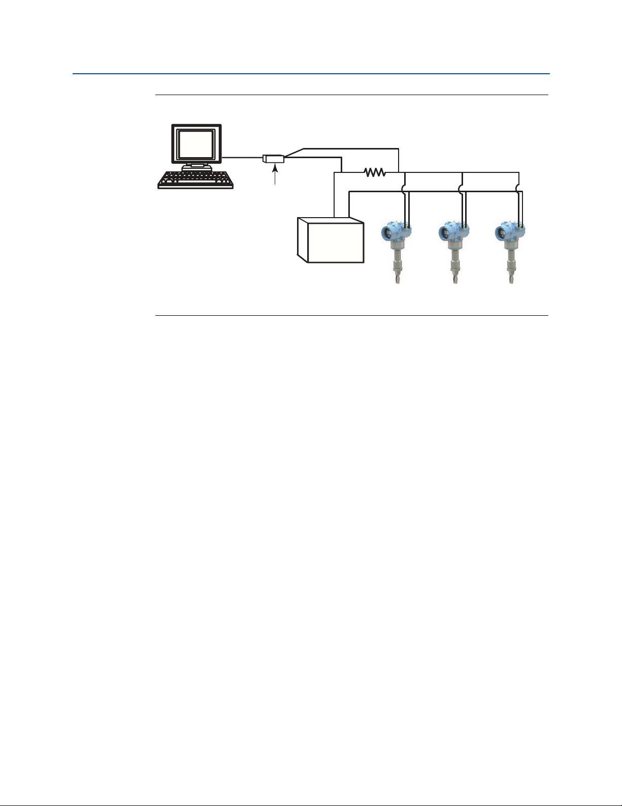
Reference Manual
A.
B.
00809-0100-4140, Rev AA
Figure 2-5. Typical Multi-drop Network
A. HART modem
B. Power supply
Configuration
January 2017
The Rosemount 2140 and Rosemount 2140:SIS are set to address zero (0) at the factory,
which allows operation in the standard point-to-point manner with a 4–20 mA output
signal.
To activate multi-drop communication, the level detector address must be changed to a
number from 1 to 15 for HART Revision 5, or 1 to 63 for HART Revision 7. This change
deactivates the 4–20 mA analog output, sending it to 4 mA. It also disables the failure
mode alarm signal, which is controlled by the upscale/downscale switch position.
Failure signals in multi-dropped devices are communicated through HART messages.
2.13.1 Communicating with a multi-dropped level detector
To communicate with a multi-drop level detector, the Field Communicator or AMS Device
Manager has to be set up for polling.
Communicating with a multi-dropped device
(Field Communicator)
1. Select Utility and Configure HART Application.
2. Select Polling Addresses, and then enter 0 to 63.
Communicating with a multi-dropped device
(AMS Device Manager)
Configuration
Click on the HART modem icon and select Scan All Devices.
41
Page 52

Configuration
January 2017
00809-0100-4140, Rev AA
2.13.2 Changing a level detector polling address
Reference Manual
Fast keys
To activate multi-drop communication, the Rosemount 2140 or Rosemount 2140:SIS poll
address must be assigned a unique number from 1 to 15 for HART 5, or 1 to 63 for HART 7.
Each device in a multi-dropped loop must have a unique poll address.
2, 2, 5 or 6, 2, 2
Changing the polling address (Field Communicator)
1. From the Home screen, select 2: Configure.
2. Select 2: Manual Setup > 6: HART > 2: Communication Settings.
3. Change the polling address.
a. In HART 5 mode, enter a polling address in the 1: Polling Address screen.
b. In HART 7 mode, enter a polling address in the 2: Change Polling Address screen.
Changing the polling address (AMS Device Manager)
1. Right click on the device and select Configure.
2. In HART 5 mode:
a. Click on Manual Setup, select the HART tab.
b. In the Communication Settings box, enter a new polling address and click Send.
3. In HART 7 mode:
a. Click on Manual Setup, and then select the HART tab.
b. Click the Change Polling Address button.
4. Carefully read the warning and click Yes if it is safe to apply the changes.
2.14 Configuring level detector security
There are four security methods with the Rosemount 2140 and Rosemount 2140:SIS.
Security switch
HART Lock
Configuration buttons lock
LOI password
42
Configuration
Page 53

Reference Manual
Without LOI display
With LOI display
A
B
00809-0100-4140, Rev AA
Figure 2-6. Alarm and Security Switches
A. Alarm switch
B. Security switch
2.14.1 Setting the security switch
Configuration
January 2017
The security switch is used to prevent changes to the configuration data.
Figure 2-6 indicates the security switch location.
If the security switch is set to the locked location ( ), any configuration requests made
using HART, LOI, or local configuration buttons are rejected and the configuration data will
not be modified.
Enabling the security switch (lock position)
1. Set process loop to manual and remove power.
2. Remove the housing cover.
3. Use a small screwdriver to slide the security switch to the lock ( ) position.
4. Replace the housing cover.
5. The cover must be fully engaged to comply with explosion-proof requirements.
Viewing the security switch status (Field Communicator)
1. From the Home screen, select 3: Service Tools.
2. Select 4: Maintenance > 6: Security.
3. Select 1: Security Switch Status.
Configuration
Viewing the security switch status (AMS device Manager)
1. Right click on the device and select Service Tools.
2. Select Maintenance, and then select the Security tab.
3. The Security Switch Status is in the Hardware box.
43
Page 54

Configuration
January 2017
Reference Manual
00809-0100-4140, Rev AA
Viewing the security switch status (LOI)
1. Press any configuration button to activate the LOI.
(See Table 2-1 on page 8 for assistance with using the LOI buttons).
2. Select VIEW CONFIG ().
3. Scroll down (
4. Exit the menu system by either waiting one minute for the EXIT MENU? prompt, or
scrolling down the menus to find and select BACK TO MENU and EXIT TO MENU.
2.14.2 HART Lock
Fast keys
The HART Lock prevents changes to the configuration data from all sources.
The HART Lock can only be set using HART communication, and is only available in HART
Revision 7 mode. The HART Lock can be enabled or disabled with a Field Communicator or
AMS Device Manager.
Configuring HART Lock (Field Communicator)
1. From the Home screen, select 2: Configure.
2. Select 2: Manual Setup. > 6: Security (or 7: Security if Scaled Variable is available).
3. Select 4: HART Lock.
4. Select the Lock or Unlock option.
) until SECURE and the status is displayed.
2, 2, 6 [or 7], 4
Configuring HART Lock (AMS device Manager)
1. Right click on the device and select Configure.
2. Select Manual Setup, and then select the Security tab.
3. Click on the Lock/Unlock button in HART Lock (Software) box.
4. Follow the screen prompts to lock or unlock.
2.14.3 Configuration button lock
Fast keys
The configuration button lock disables all local button functionality. Changes to the
configuration using the LOI and local buttons will be rejected. Local external buttons can be
locked using HART communication only.
44
2, 2, 6 [or 7], 3
Configuration
Page 55

Reference Manual
00809-0100-4140, Rev AA
Configuring the configuration button lock
(Field Communicator)
1. From the Home screen, select 2: Configure.
2. Select 2: Manual Setup > 6: Security (or 7: Security if Scaled Variable is available).
3. Select 3: Configuration Buttons.
4. Select the Disable option to lock, or the Enabled option to unlock.
Configuring the configuration button lock
(AMS device Manager)
1. Right click on the device and select Configure.
2. Select Manual Setup, and then select the Security tab.
3. Within the Configuration Buttons drop-down menu, select Disabled to lock the
Configuration
January 2017
external local buttons or Enabled to unlock.
4. Click Send.
5. Confirm service reason and click Yes.
2.14.4 Local Operator Interface (LOI) password
Fast keys
A Local Operator Interface password can be entered and enabled to prevent review and
modification of device configuration using the LOI.
This password protection does not prevent configuration from HART or external buttons.
A LOI password is a 4-digit code that is to be set by the user.
LOI password protection can be configured and enabled/disabled by HART communication
using a Field Communicator, AMS Device Manager, or the LOI.
Configuring LOI password (Field Communicator)
1. From the Home screen, select 2: Configure.
2. Select 2: Manual Setup. > 6: Security (or 7: Security if Scaled Variable is available).
3. Select 5: LOI Password Protection.
2, 2, 6 [or 7], 5
Configuration
4. Select the Enabled option.
5. Enter a 4-digit number as the password.
45
Page 56

Configuration
January 2017
Reference Manual
00809-0100-4140, Rev AA
Configuring LOI password (AMS Device Manager)
1. Right click on the device and select Configure.
2. Select Manual Setup, and then select the Security tab.
3. Within the Local Operator Interface box, click the Configure Password button.
4. Follow the screen prompts:
a. Enable the LOI password protection.
b. Enter a 4-digit number as the password.
Configuring LOI password (using Local Operator Interface)
1. Press any LOI button to activate the menu.
(See Table 2-1 on page 8 for assistance with using the LOI buttons).
2. Scroll down (
3. Scroll down (
4. Enable the LOI password protection.
5. Enter a 4-digit number as the password.
6. Exit the menu system by either waiting one minute for the EXIT MENU? prompt, or
scrolling down the menus to find and select BACK TO MENU and EXIT TO MENU.
) and then select EXTENDED MENU ().
) and then select PASSWORD ().
2.15 Setting the alarm switch
On the electronics board is an alarm switch (see Figure 2-6 on page 43).
Follow the steps below to configure the alarm switch.
1.
2. Remove the housing cover.
3. Use a small screwdriver to slide the alarm switch to desired position.
4. Replace the housing cover.
5. The cover must be fully engaged to comply with explosion-proof requirements.
Set process loop to manual and remove power.
46
Configuration
Page 57

Reference Manual
Hardware Installation
00809-0100-4140, Rev AA
Section 3 Hardware Installation
3.1 Safety messages
Procedures and instructions in this section may require special precautions to ensure the
safety of the personnel performing the operation. Information that raises potential safety
issues is indicated by a warning symbol ( ). The external hot surface symbol ( ) is used
when a surface is hot and care must be taken to avoid possible burns. If there is a risk of an
electrical shock, the ( ) symbol is used. Refer to the following safety messages before
performing an operation preceded by this symbol.
Failure to follow these installation guidelines could result in death or serious
injury.
The Rosemount 2140 Level Detector and Rosemount 2140:SIS Level Detector
(“level detectors”) must be installed, connected, commissioned, operated, and
maintained by suitably qualified personnel only, observing any national and local
requirements that may apply.
Ensure the wiring is suitable for the electrical current and the insulation is suitable
for the voltage, temperature, and environment.
Use the equipment only as specified in this manual. Failure to do so may impair the
protection provided by the equipment.
Any substitution of non-recognized parts may jeopardize safety and is under no
circumstances allowed.
The weight of a level detector with a heavy flange and extended fork length may
exceed 37 lb. (18 kg). A risk assessment is required before carrying, lifting, and
installing the level detector.
Failure to comply with the following requirements will result in the invalidation of
the product safety certification.
Check for risk of process medium build-up on the level switch forks.
Avoid situations where drying and coating products may create an excessive
build-up (see Figure 3-3 on page 51) or implement preventative maintenance
programs to ensure the build-up is not enough to impair performance.
Ensure there is no risk of 'bridging' the level switch forks. Examples of products
that create 'bridging' of the forks are dense paper slurries and bitumen.
Explosions could result in death or serious injury.
Installation of this level detector in a hazardous area environment must be in
accordance with the appropriate local, national, and international standards,
codes, and practices.
Please review Appendix B: Product Certifications for restrictions associated with
hazardous area installation.
Before connecting a Field Communicator in an explosive atmosphere, ensure the
instruments in the loop are installed in accordance with intrinsically safe or
non-incendive field wiring practices.
In an explosion-proof/flameproof installation, do not remove the level detector
covers when power is applied to the unit.
January 2017
Hardware Installation
47
Page 58

Hardware Installation
January 2017
External surface may be hot.
Care must be taken to avoid possible burns.
Process leaks may cause harm or result in death.
Install and tighten process connectors before applying pressure.
Do not attempt to loosen or remove process connectors while a level detector is in
Electrical shock can result in death or serious injury.
If the level detector is installed in a high voltage environment and a fault condition
Use extreme caution when making contact with the leads and terminals.
Make sure that power to the level detector is off while making connections.
Replacement equipment or spare parts not approved by Emerson for use as spare
parts could reduce the pressure retaining capabilities of the level detector and
may render the instrument dangerous.
Use only spare parts supplied or sold by Emerson.
Reference Manual
00809-0100-4140, Rev AA
service.
or installation error occurs, high voltage may be present on leads and terminals.
3.2 Considerations before installation
Important
Emerson is not in a position to evaluate or guarantee the compatibility of the process fluid
or other process parameters with the product, options, configuration or materials of
construction selected.
3.2.1 Safety considerations
Control drawings for hazardous area installations are in Appendix B: Product Certifications,
and there are safety instructions in the Rosemount 2140 Product Certifications Manual
(see Emerson.com/Rosemount for other language versions).
3.2.2 Environmental considerations
The Rosemount 2140 Level Detector and Rosemount 2140:SIS Level Detector are wired
point level detectors, and are available as Intrinsically Safe (IS) or explosion-proof/flameproof versions for hazardous area installations. There are also ordinary location versions for
unclassified, safe areas. Approvals are listed in Appendix B: Product Certifications of this
manual.
These level detectors are designed for open or closed tanks, and pipe installation. It is
weatherproof and protected against the ingress of dust, but must be protected from
flooding. Avoid installing the level detector near heat sources.
48
Hardware Installation
Page 59

Reference Manual
00809-0100-4140, Rev AA
Figure 3-1. Environmental Considerations
Hardware Installation
January 2017
3.2.3 Application considerations
For most liquids, including coating, aerated liquids and slurries, the function is virtually
unaffected by flow, turbulence, bubbles, foam, vibration, solid particles, build-up, or
properties of the liquid.
The Rosemount 2140 and 2140:SIS Level Detectors (“level detectors”) are available as
Intrinsically Safe (IS) or explosion-proof/flameproof versions for hazardous area
installations. There are also ordinary location versions for unclassified, safe areas.
The level detectors can be mounted in an open or closed tank, or a pipe. There is a wide
range of threaded, flanged, and hygienic process connection options.
Supported process temperature ranges are dependent on the selected Operating
Temperature code in the model number.
2140****M is the mid range option: -40 °F (-40 °C) to 356 °F (180 °C)
2140****E is the high range option: -94 °F (-70 °C) to 500 °F (260 °C)
If applicable, see also Appendix B: Product Certifications for the process temperature range
limits required to comply with hazardous area product approvals.
OKOK
Hardware Installation
49
Page 60

Hardware Installation
SP
HY
SP
0.1 in.
(2.5 mm)
0.5 in.
(13 mm)
0.5 in.
(13 mm)
January 2017
Application limits
Check for risk of process medium build-up on the level switch forks.
Ensure there is no risk of ‘bridging’ the level switch forks. Examples of products that
Problems may occur if product coats and dries causing caking.
Ensure the process is operating within the instrument operating temperature and
Ensure the liquid viscosity is within the recommended viscosity range
Check that the liquid density is higher than 0.4 SG (400 kg/m
Liquid density affects the switch-point e.g. dry-to-wet (see Figure 3-2 on page 50).
The Rosemount 2140 and 2140:SIS are normally insensitive to foams (i.e. they do
Reference Manual
00809-0100-4140, Rev AA
Avoid situations where a drying and coating process medium may create an
excessive build-up (see Figure 3-3 on page 51) or implement preventative
maintenance programs to ensure the build-up is not enough to impair
performance.
can create ‘bridging’ of forks are dense paper slurries and bitumen.
pressure ranges (see “Specifications” on page 103).
(see “Specifications” on page 103).
3
)
(see “Specifications” on page 103).
not see the foam). However, on rare occasions, some very dense foams may be
seen as liquid; known examples of this are found in ice-cream and orange juice
manufacturing.
Figure 3-2. Level Detection Switching Point
SP: Switching point (H20)
HY: Switching point hysteresis
50
Hardware Installation
Page 61

Reference Manual
OK
00809-0100-4140, Rev AA
Note
When mounted vertically, a low density process medium has a switching point closer to the
process connection. A high density process medium has a switching point closer to fork tip.
Figure 3-3. Avoid Product Build-up
Hardware Installation
January 2017
3.2.4 Installation considerations
Measurement accuracy is dependent upon the proper installation of the level detector.
Keep in mind the need for easy access, personnel safety, practical field calibration, and a
suitable environment for the level detector.
For dimensional drawings, see “Dimensional drawings” on page 106.
Device identification
To identify the Rosemount 2140 version, see the labels on the housing.
Electronics housing clearances
Mount the level detector in a position to allow easy access to the terminals.
Provide 0.75 in. (19 mm) of clearance for a standard cover to be removed. If an LCD display
is installed, provide 3 in. (76.2 mm) of clearance for the extended cover to be removed.
For dimensional drawings, see “Dimensional drawings” on page 106.
Covers installation
Always ensure a proper seal by installing the electronics housing covers so that metal
contacts metal. Use Rosemount O-rings.
Hardware Installation
51
Page 62
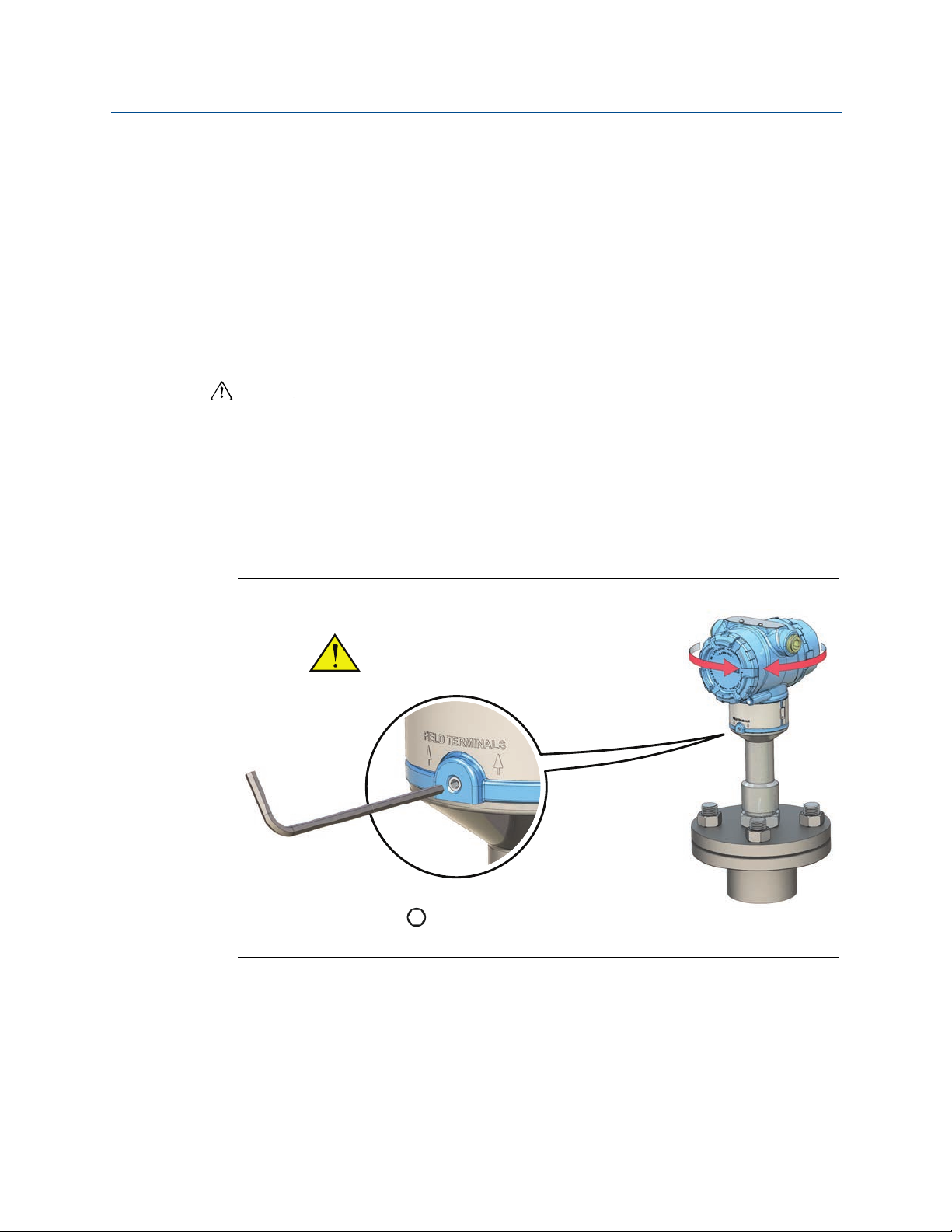
Hardware Installation
H3/32 in.
Torque 30 in-lb (3 Nm)
Do not attempt to rotate the
display beyond the thread limits.
January 2017
Grounding
Always ground the housing in accordance with national and local electrical codes.
The most effective grounding method for the housing is a direct connection to earth
ground with minimal impedance. Housings have an external earth ground point for making
this connection.
Adjust display rotation
To rotate the housing (Figure 3-4), perform the following procedure:
Reference Manual
00809-0100-4140, Rev AA
1.
2. First, rotate the housing clockwise to the desired location.
3. Re-tighten the set screw.
Figure 3-4. Housing Rotation
Loosen the set screw until the level detector housing can rotate smoothly.
a. Do not unscrew all the way. Rotating the housing, without this screw in place, can
damage the internal wiring.
a. If the desired location cannot be achieved due to the internal thread limit, rotate
the housing counterclockwise
How to handle the Rosemount 2140
The weight of the level detector with a heavy flange and extended fork length may exceed
37 lb. (18 kg). A risk assessment is required before carrying, lifting, and installing the
Rosemount 2140.
Use both hands to carry the level detector, and do not hold using the forks (Figure 3-5).
52
Hardware Installation
Page 63
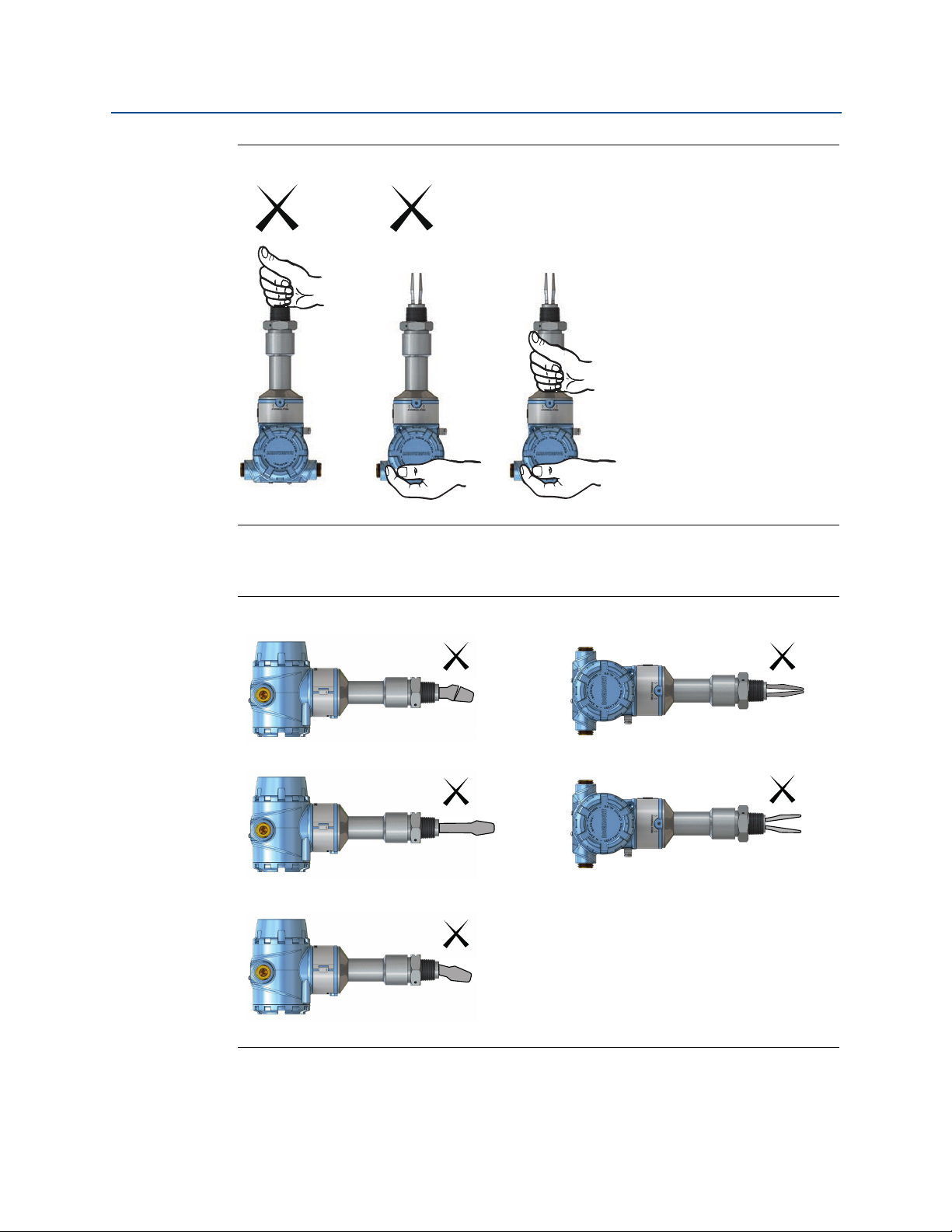
Reference Manual
OK
00809-0100-4140, Rev AA
Figure 3-5. Handling the Rosemount 2140
Hardware Installation
January 2017
Do not change the Rosemount 2140 in any way
Figure 3-6. Do Not Change the Rosemount 2140
Hardware Installation
53
Page 64

Hardware Installation
January 2017
Installation recommendations
Avoid installing near to liquid entering the tank at the fill point.
Avoid heavy splashing on the forks.
Ensure that the forks do not come into contact with the tank wall, any internal
Ensure there is sufficient distance between build-up on the tank wall and the fork
Ensure the installation does not create tank crevices around the forks where liquid
Extra consideration is needed if the plant vibration is close to the 1400 Hz.
Supporting the fork extension tube avoids long fork length vibration
Reference Manual
00809-0100-4140, Rev AA
Increasing the sensor output delay reduces accidental switching caused by
splashing (see “Sensor output delay” on page 16).
fittings, or obstructions.
(see Figure 3-3 on page 51).
may collect. This can happen with high-viscosity and high-density liquids.
operating frequency of the Rosemount 2140.
(see Figure 3-7 on page 55).
54
Hardware Installation
Page 65

Reference Manual
3.28 ft. (1.0 m)
3.28 ft. (1.0 m)
Maximum
3.28 ft.
(1.0 m)
3.28 ft.
(1.0 m)
3.28 ft.
(1.0 m)
Maximum
3.28 ft. (1.0 m)
00809-0100-4140, Rev AA
Figure 3-7. Required Supports for Extended Fork
Hardware Installation
January 2017
OK
OK
OK
OK
Hardware Installation
55
Page 66

Hardware Installation
A
B
A
B
B
B
B
A
A
A
A
B
B
A
January 2017
3.2.5 Installation examples
Figure 3-8. High and Low Level Alarms
A. Dry
B. Wet
Figure 3-9. Pump Control or Overfill Protection
Reference Manual
00809-0100-4140, Rev AA
A. Dry
B. Wet
Figure 3-10. Pump or Empty Pipe Protection
A. Dry
B. Wet
56
Hardware Installation
Page 67

Reference Manual
A
C
B
D
E
F
00809-0100-4140, Rev AA
3.3 Installation procedures
For dimensional drawings, see Appendix A: Specifications and Reference Data on page 106.
3.3.1 Process connection seals
Figure 3-11. Process Connection Seals
Hardware Installation
January 2017
Hardware Installation
A. PTFE
B. NPT or BSPT (R) thread
C. Gasket
D. BSPP (G) thread
E. Tri Clamp
F. The Tri Clamp seal is supplied as an as accessory kit (see page 119)
57
Page 68

Hardware Installation
A
B
C
January 2017
3.3.2 Correct fork alignment
Ensure the fork is correctly aligned by using the notches and grooves as indicated in
Figure 3-12.
Figure 3-12. Correct Fork Alignment
Reference Manual
00809-0100-4140, Rev AA
A. Alignment groove on standard length Rosemount 2140
B. Alignment notch on flanged Rosemount 2140
C. Alignment notch on extended length Rosemount 2140
Pipe installation
Figure 3-13. Pipe Installation
OK
58
Hardware Installation
Page 69

Reference Manual
OKOK
OK
OK
OK
OK
00809-0100-4140, Rev AA
Tank installation
Figure 3-14. Tank Installation
Hardware Installation
January 2017
Hardware Installation
59
Page 70

Hardware Installation
OK
A
B
A
January 2017
00809-0100-4140, Rev AA
3.3.3 Tightening the threaded Rosemount 2140
Figure 3-15. Tightening the Threaded Rosemount 2140
3.3.4 Insulation
Figure 3-16. Insulation
Reference Manual
60
A. 3.9 in. (100 mm) clearance all around
B. ROCKWOOL
®
Hardware Installation
Page 71

Reference Manual
00809-0100-4140, Rev AA
Electrical Installation
Section 4 Electrical Installation
4.1 Safety messages
Procedures and instructions in this section may require special precautions to ensure the
safety of the personnel performing the operations. Information that raises potential safety
issues is indicated by a warning symbol ( ). Refer to the following safety messages before
performing an operation preceded by this symbol.
Explosions could result in death or serious injury.
Installation of Rosemount 2140 and 2140:SIS Level Detectors (“level detectors”)
in an explosive environment must be in accordance with the appropriate local,
national, and international standards, codes, and practices.
Please review Appendix B: Product Certifications for any restrictions associated
with a safe installation.
Before connecting a Field Communicator in an explosive atmosphere, ensure the
instruments in the loop are installed in accordance with intrinsically safe or
non-incendive field wiring practices.
In an explosion-proof/flameproof installation, do not remove the level detector
covers when power is applied to the unit.
Covers are not to be removed in extreme environmental conditions. The internals
must be kept free from moisture and conductive dust.
Process leaks may cause harm or result in death.
Install and tighten process connectors before applying pressure.
Electrical shock can result in death or serious injury.
Avoid contact with the leads and terminals. High voltage that may be present on
leads can cause electrical shock.
January 2017
Electrical Installation
Make sure all electrical installation is in accordance with national and local code
requirements.
Do not run signal wiring in conduit or open trays with power wiring or near heavy
electrical equipment.
For explosion-proof and ordinary locations installations in accordance with the
National Electrical Code, ANSI/NFPA 70 or the Canadian Electrical Code, C22.1., the
Rosemount 2140 is to be supplied by a Class 2 or Limited Energy Source.
61
Page 72

Electrical Installation
Voltage (Vdc)
Load (s)
Operating
Region
1387
1000
500
0
10.5 20 30
42.4
January 2017
4.2 Cable selection
Wiring should be adequately rated and not be susceptible to mechanical damage.
Electrical conduit is commonly used to protect wiring. The wiring to this device must
maintain creepage(1) and clearance distances. Therefore, the conductors stripping length
should be no greater than 6 mm and be free from stray strands.
Use shielded twisted pairs to get the best results. To ensure proper communications, use
24 AWG, to a maximum of 14 AWG, and do not exceed 5000 ft. (1500 m). Cable length is
limited by the selection of monitoring resistance and wire gauge.
All power to the level detector is supplied over the signal wiring. Signal wiring does not need
to be shielded, but use twisted pairs for best results. Do not run unshielded signal wiring in
conduit or open trays with power wiring, or near heavy electrical equipment. For high
EMI/RFI environments, shielded twisted pair cable should be used.
4.3 Cable gland/conduit
Reference Manual
00809-0100-4140, Rev AA
For explosion-proof/flameproof installations, only use cable glands/conduit entry devices
certified as explosion-proof/flameproof. For ordinary location installations, use suitably
rated cable glands to maintain the IP rating.
Un-used conduit entries must be sealed with a suitably rated blanking plug.
See “Conduit entries” on page 103 for all other details.
4.4 Power supply
Terminals in the housing provide connections for signal wiring.
Rosemount 2140 and Rosemount 2140:SIS Level Detectors (“level detectors”) operate with
the following power supplies:
10.5 to 42.4 Vdc (10.5 to 30 Vdc in Intrinsically Safe installations).
For HART communication, a minimum loop resistance of 250 is required. Maximum loop
resistance is determined by the voltage level of the external power supply (Figure 4-1).
Figure 4-1. Load Limitation
62
Maximum Loop Resistance = 43.5 * (External Power Supply Voltage – 10.5)
Electrical Installation
Page 73
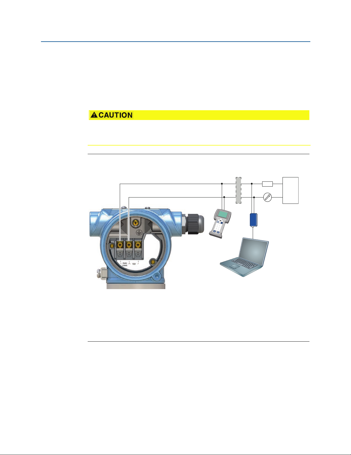
Reference Manual
-
+
-
+
Fn
1
2
3
4
5
6
7
8
9
0
-
.
A
B
D
E
F
C
00809-0100-4140, Rev AA
4.5 Hazardous areas
When the level detector is installed in hazardous areas, local regulations and specifications
in applicable certificates must be observed.
4.6 Wiring diagram
Do not connect the power signal wiring to the test terminals.
Incorrect wiring can damage the test circuit.
Figure 4-2. 4-20 mA/HART® Communication
Electrical Installation
January 2017
A. Field Communicator (IS approved for intrinsically safe installations)
B. Approved IS barrier (for intrinsically safe installations only)
C. HART modem
D. Load resistance (250)
E. Current meter
F. Power supply
4.7 Grounding
Always ground the housing in accordance with national and local electrical codes. Failure to
do so may impair the protection provided by the equipment.
Electrical Installation
63
Page 74
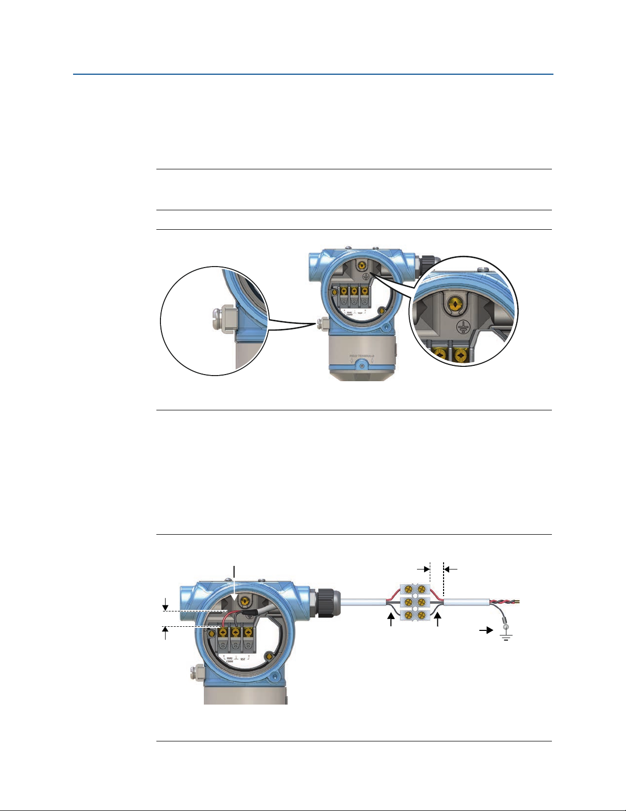
Electrical Installation
B
A
A
B
B
C
C
D
January 2017
4.7.1 Level switch grounding
The most effective grounding method is a direct connection to earth ground with minimal
impedance (< 1). Figure 4-3 on page 64 shows the two grounding screw connections
provided on the level detector.
Note
Grounding the level detector using a threaded conduit connection may not provide a
sufficient ground.
Figure 4-3. Ground Screws
Reference Manual
00809-0100-4140, Rev AA
A. External ground screw
B. Internal ground screw
4.7.2 Signal cable shield grounding
Make sure the instrument cable shield is:
trimmed close and insulated from touching the level detector housing.
continuously connected throughout the segment.
connected to a good earth ground at the power supply end.
Figure 4-4. Cable Shield
64
A. Trim shield and insulate C. Trim shield
B. Minimize distance D. Connect shield back to power supply ground
Electrical Installation
Page 75
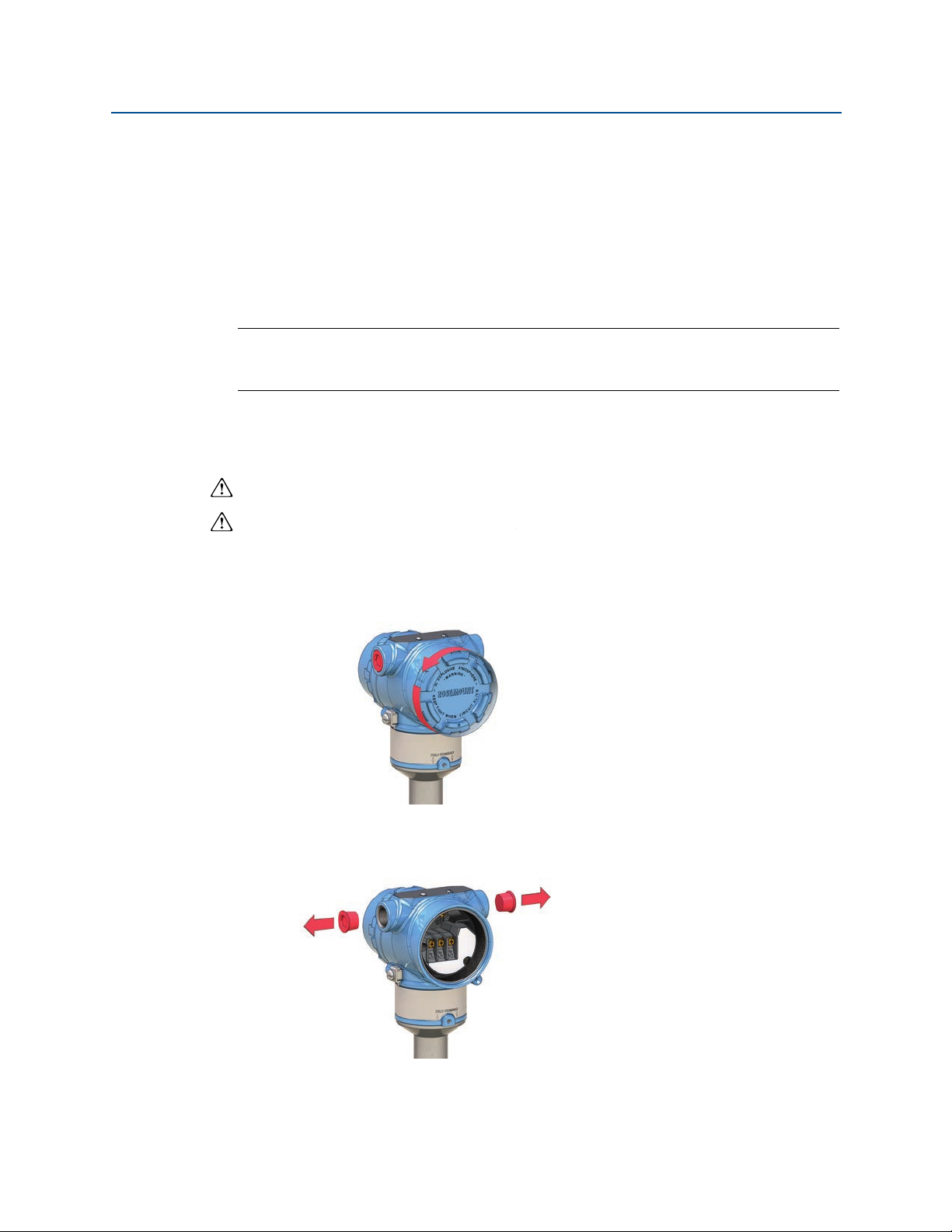
Reference Manual
00809-0100-4140, Rev AA
Electrical Installation
4.7.3 Transient protection terminal block grounding
The level detector can withstand electrical transients of the energy level usually
encountered in static discharges or induced switching transients. However, high-energy
transients, such as those induced in wiring from nearby lightning strikes, can damage the
level detector.
A transient protection terminal block can be ordered as an installed option (code T1). The
lightning bolt symbol in identifies the transient protection terminal block.
Note
The transient protection terminal block does not provide transient protection unless the
housing is properly grounded.
4.8 Wiring and power-up
1. Verify the power supply is disconnected.
January 2017
2. Remove the field terminals cover.
In an explosion-proof/flameproof installation, do not remove the level detector
covers when power is applied to the unit. Covers are also not to be removed in
extreme environmental conditions.
3. Remove the plastic plugs
Electrical Installation
65
Page 76

Electrical Installation
½-14 NPT
M20 x 1.5
M20(No marking)
Identification of
thread size and type
Torque 7 in-lb (0.8 Nm)
January 2017
4. Pull the cable through the cable gland/conduit.
Reference Manual
00809-0100-4140, Rev AA
5. Connect the cable wires (see also Figure 4-2 on page 63)
6. Ensure proper grounding (see “Grounding” on page 63).
7. Tighten the cable gland.
Apply PTFE tape or other sealant to the threads.
.
66
Electrical Installation
Page 77
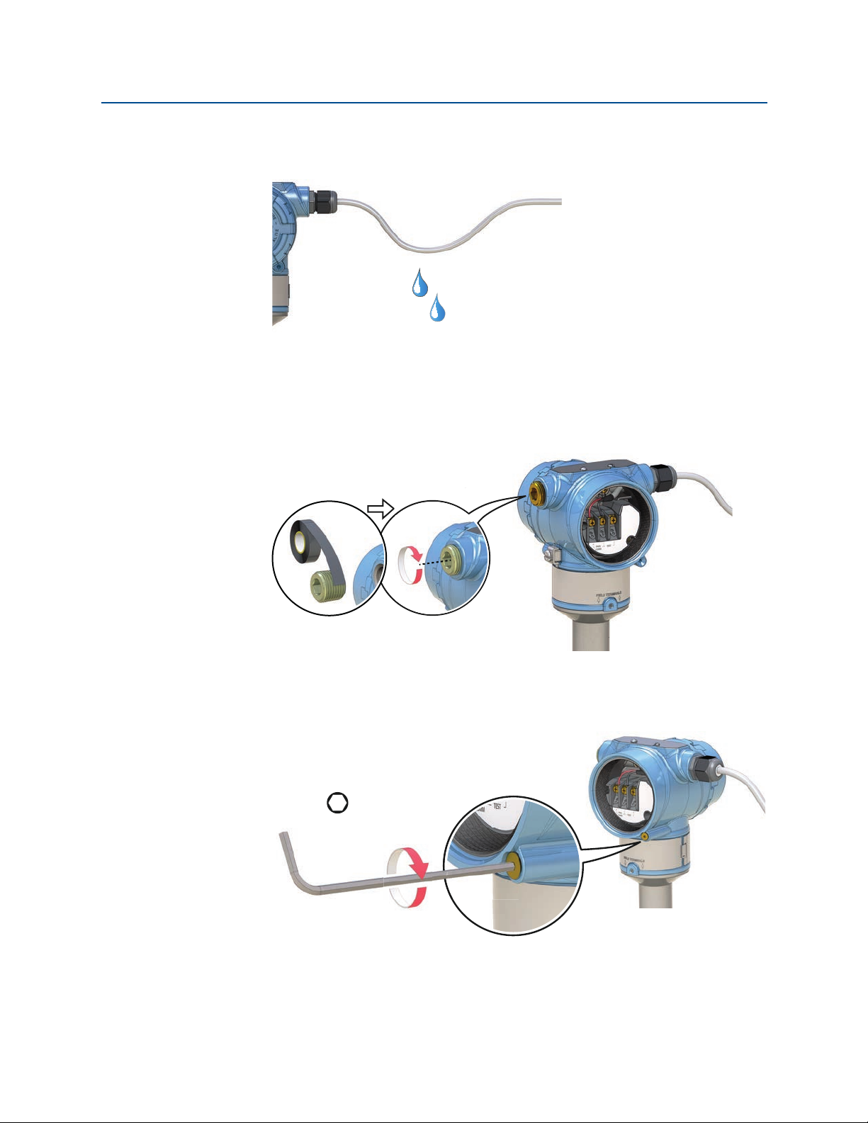
Reference Manual
M2.5
Cover jam screw
(one per side)
00809-0100-4140, Rev AA
8. Arrange the wiring with a drip loop.
9. Plug and seal the unused conduit connection to avoid moisture and dust
Electrical Installation
January 2017
accumulation inside the housing.
Apply PTFE tape or other sealant to the thread.
Electrical Installation
10. Re-fit the field terminals housing cover.
a. Verify the cover jam screws are completely threaded into the housing.
67
Page 78
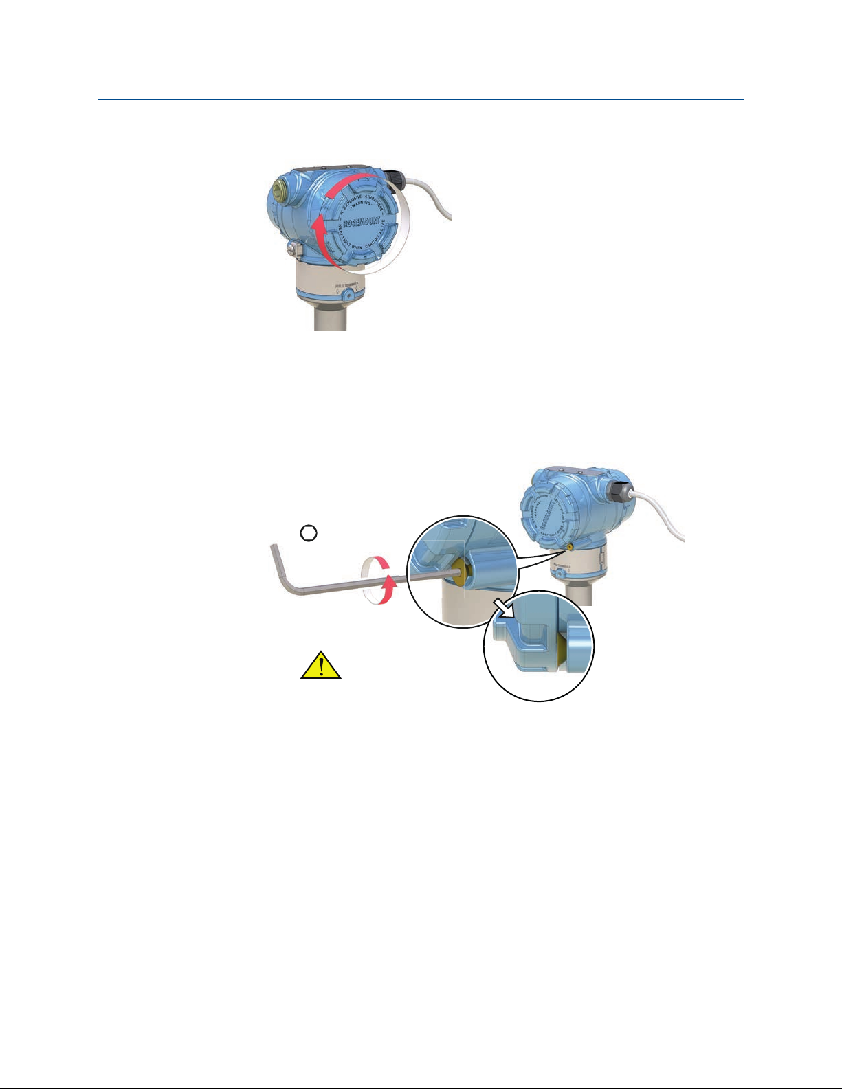
Electrical Installation
M2.5
Verify that the covers
cannot be removed.
January 2017
b. Attach and tighten the covers. Make sure the covers are fully engaged.
11. Required for explosion-proof/flameproof installations only:
a. Turn the cover jam screw counterclockwise until it contacts the cover.
b. Turn the jam screw an extra
Reference Manual
00809-0100-4140, Rev AA
The cover must be fully engaged to comply with explosion-proof requirements.
1
/2 turn counterclockwise to secure the cover.
68
12. Connect the power supply.
Electrical Installation
Page 79

Reference Manual
00809-0100-4140, Rev AA
Operation and Maintenance
January 2017
Section 5 Operation and Maintenance
5.1 Overview
This section contains information on calibrating and testing the Rosemount 2140 and
Rosemount 2140:SIS. Field Communicator, AMS, and Local Operator Interface (LOI)
instructions are given to perform configuration functions.
5.2 Safety messages
Procedures and instructions in this section may require special precautions to ensure the
safety of the personnel performing the operations. Information that raises potential safety
issues is indicated by a warning symbol ( ). Refer to the following safety messages before
performing an operation preceded by this symbol.
Explosions could result in death or serious injury.
Installation of this Rosemount 2140 and 2140:SIS Level Detector (“level detectors”) in
an explosive environment must be in accordance with the appropriate local, national,
and international standards, codes, and practices.
Please review Appendix B: Product Certifications for any restrictions associated with a
safe installation.
Before connecting a Field Communicator in an explosive atmosphere, ensure the
instruments in the loop are installed in accordance with intrinsically safe or
non-incendive field wiring practices.
In an explosion-proof/flameproof installation, do not remove the level detector
covers when power is applied to the unit.
Process leaks may cause harm or result in death.
Install and tighten process connectors before applying pressure.
Electrical shock can result in death or serious injury.
Avoid contact with the leads and terminals. High voltage that may be present on
leads can cause electrical shock.
Operation and Maintenance
69
Page 80

Operation and Maintenance
A
A
B
B
mA output
mA output
January 2017
5.3 Analog output calibration
The analog output can be calibrated to match the user's measurement system. The Analog
Output Trim (4-20mA Output Trim) will calibrate the loop at the 4 mA and 20 mA points.
5.3.1 Trimming the analog output
The Analog Output Trim commands allow you to adjust the level detector’s current output at
the 4 and 20 mA points to match the plant standards. This trim is performed after the
digital to analog conversion so only the 4-20mA analog signal will be affected. Figure 5-1
graphically shows the two ways the characterization curve is affected when an analog
output trim is performed.
Figure 5-1. Analog Output Trim Example
Reference Manual
00809-0100-4140, Rev AA
A. Before trim
B. After Trim
Note
If a resistor is added to the loop, ensure that the power supply is sufficient to power the level
detector to a 20 mA output with additional loop resistance. Refer to “Power supply” on
page 62.
5.3.2 Site calibration of analog output
Fast Keys
This command starts the on-site calibration of the analog output. It should only be
performed by authorized persons.
Note
A reference meter (ammeter) is a required for measuring the actual output current at 4 mA
and 20 mA. See “Wiring diagram” on page 63 for the analog output connections.
3, 4, 4, 2
70
Operation and Maintenance
Page 81

Reference Manual
00809-0100-4140, Rev AA
To start the on-site calibration (Field Communicator)
1. From the Home screen, select 3: Service Tools.
2. Select 4: Maintenance > 4: Calibrate Analog.
3. Select 2: Calibrate.
4. Follow on-screen instructions to perform the calibration of 4 mA and 20 mA.
Note
In the Calibrate Analog menu, the 4: Analog Output option indicates the live output
current output and the 5: Percent Range option indicates the percentage of that output
current in terms of the complete 4–20 mA range. For example, 8 mA is 25% of range, 12 mA
is 50%, etc.
Note
When messages about the loop appear, take appropriate safe action and select “OK”.
See “Configuration basics” on page 10 for further information.
Operation and Maintenance
January 2017
To start the on-site calibration (AMS Device Manager)
1. Right click on the device and select Service Tools.
2. Select Maintenance, and then select the Calibrate Analog tab.
3. Click on the Calibrate button in the Analog box.
4. Follow on-screen instructions to perform the calibration of 4 mA and 20 mA.
Note
The Analog Output device variable indicates the live output current output, and the
Percent of Range device variable indicates the percentage of that output current in terms
of the complete 4–20 mA range. For example, 8 mA is 25% of range, 12 mA is 50%, etc.
Note
When messages about the loop appear, take appropriate safe action.
See “Configuration basics” on page 10 for further information.
Operation and Maintenance
71
Page 82

Operation and Maintenance
January 2017
To start the on-site calibration (using LOI)
1. Press any LOI button to activate the menu.
(See Table 2-1 on page 8 for assistance with using the LOI buttons).
Reference Manual
00809-0100-4140, Rev AA
2. Scroll down (
3. Select CALIBRATE ().
4. Scroll down (
5. Follow on-screen instructions to perform the calibration of 4 mA and 20 mA.
6. Exit the menu system by either waiting one minute for the EXIT MENU? prompt, or
scrolling down the menus to find and select BACK TO MENU and EXIT TO MENU.
Note
When messages about the loop appear, take appropriate safe action and select “”.
See “Configuration basics” on page 10 for further information.
) and then select EXTENDED MENU ().
) and then select ANALOG TRIM ().
5.3.3 Restoring factory calibration of the analog output
Fast Keys
The Recall Factory Trim—Analog Output command allows the restoration of the as-shipped
factory settings of the analog output trim. This command can be useful for recovering from
an inadvertent trim, incorrect Plant Standard or faulty meter. It is accessible after a site
calibration has been performed, but should only be performed by authorized persons.
3, 4, 4, 3
72
To restore the factory calibration (Field Communicator)
1. From the Home screen, select 3: Service Tools.
2. Select 4: Maintenance > 4: Calibrate Analog.
3. Select 3: Restore Factory Calibration.
4. Follow on-screen instructions to restore the calibration.
Note
A Restore Site Calibration command becomes available afterwards.
Note
When messages about the loop appear, take appropriate safe action and select “OK”.
See “Configuration basics” on page 10 for further information.
Operation and Maintenance
Page 83

Reference Manual
00809-0100-4140, Rev AA
To restore the factory calibration (AMS Device Manager)
1. Right click on the device and select Service Tools.
2. Select Maintenance, and then select the Calibrate Analog tab.
3. Click on the Restore Factory Calibration in the Analog box.
4. Follow on-screen instructions to restore the calibration.
Note
A Restore Site Calibration command becomes available afterwards.
Note
When messages about the loop appear, take appropriate safe action.
See “Configuration basics” on page 10 for further information.
To restore the factory calibration (LOI)
Operation and Maintenance
January 2017
1. Press any LOI button to activate the menu.
(See Table 2-1 on page 8 for assistance with using the LOI buttons).
2. Scroll down (
3. Select CALIBRATE ().
4. Scroll down (
5. Scroll down (
6. Follow on-screen instructions to restore the calibration.
7. Exit the menu system by either waiting one minute for the EXIT MENU? prompt, or
scrolling down the menus to find and select BACK TO MENU and EXIT TO MENU.
Note
When messages about the loop appear, take appropriate safe action and select “”.
See “Configuration basics” on page 10 for further information.
) and then select EXTENDED MENU ().
) and then select PARAMETR RECALL ().
) and then select ANALOG RECALL ().
5.4 Performing tests and simulations
5.4.1 Device tests (partial proof test)
The Rosemount 2140 Level Detector (“level detector”) has device-testing functionality.
Checks include:
Critical RAM
Program ROM
Configuration storage non-volatile memory
Device supply voltage
Operation and Maintenance
73
Page 84

Operation and Maintenance
January 2017
The level detector can be configured to exercise the analog output to produce the currents
representing the lower and upper range values (page 26) and alarm current (page 33).
If the level detector has the Extended Features Package (EFP) and the Scaled Variable or
Sensor Frequency is assigned to the PV, the analogue output is also exercised from the low
saturation level to the high saturation level (page 33).
By default, the device-testing sequence is not started at every power-up. It can be started
by an operator through the LOI menu system i.e. TEST > DEVICE TEST or, when no LOI is not
fitted, by using an optional single external push-button fitted to the top of the level
detector (underneath the movable nameplate).
There are optional settings to configure:
Duration of the whole testing sequence
(each phase takes an equal division of that total time).
Enable/disable device-testing at start-up.
To change device-test parameters (Field Communicator)
Reference Manual
00809-0100-4140, Rev AA
1. From the Home screen, select 2: Configure.
2. Select 2: Manual Setup > 1: Operation > 2: Device Test.
3. Choose the device-test parameter to change:
a. Select 1: Duration for setting how long the device-test lasts.
b. Select 2: Start-up Device-Test for setting if device-testing at start-up is
enabled/disabled.
Note
When messages about the loop appear, take appropriate safe action and select “OK”.
See “Configuration basics” on page 10 for further information.
To change device-test parameters (AMS Device Manager)
1. Right click on the device and select Configure.
2. Select Manual Setup, and then select the Operation tab.
3. Edit the Duration field if changing the setting for how long the device-test lasts.
4. Select enabled or disabled at the Start-up Device Test field.
74
Note
When messages about the loop appear, take appropriate safe action.
See “Configuration basics” on page 10 for further information.
Operation and Maintenance
Page 85

Reference Manual
00809-0100-4140, Rev AA
To change device-test parameters (LOI)
1. Press any LOI button to activate the menu.
Operation and Maintenance
January 2017
(See Table 2-1 on page 8 for assistance with using the LOI buttons).
2. Scroll down (
3. Scroll down (
4. Choose the device-test parameter to change:
c. Select DURATION for setting how long the test lasts.
d. Select START-UP for setting if device-testing at start-up is enabled/disabled.
5. Exit the menu system by either waiting one minute for the EXIT MENU? prompt, or
scrolling down the menus to find and select BACK TO MENU and EXIT TO MENU.
Note
When messages about the loop appear, take appropriate safe action and select “”.
See “Configuration basics” on page 10 for further information.
5.4.2 Proof tests
The Rosemount 2140:SIS must be tested at regular intervals to detect any failures not
automatically detected by the device self-test at start-up and the continuous fork sensor
diagnostics when operating in Enhanced mode (page 14).
For full information about proof testing the Rosemount 2140:SIS, refer to the Functional
Safety Manual.
) and then select EXTENDED MENU ().
) and then select DEVICE TEST ().
5.4.3 Verifying alarm level (optional)
If the electronics board, sensor module, or LOI display is repaired or replaced, verify the
alarm current level before returning the level detector to service. This is useful in testing the
reaction of the control system to a level detector in an alarm state. Thus ensuring the
control system recognizes the alarm when activated.
To verify alarm values, run an analog loop test with the simulate alarm option selected
(page 76). Ensure that the alarm switch is in the required high or low position (page 46).
Note
Before returning to service, verify the security switch is set to the correct position.
Refer to “Setting the security switch” on page 43.
Operation and Maintenance
75
Page 86

Operation and Maintenance
January 2017
5.4.4 Analog loop test (optional)
This test verifies the analog output of the level detector, the integrity of the loop, and the
operations of any recorders or similar devices installed in the loop.
It is recommended that the 4-20 mA points, in addition to alarm levels, are verified when
installing, repairing, or replacing a level detector.
The host system may provide a current measurement for the 4-20 mA HART output.
If not, connect a reference meter (ammeter) to the level detector by either connecting the
meter to the test terminals on the terminal block, or shunting level detector power through
the meter at some point in the loop.
Reference Manual
00809-0100-4140, Rev AA
Fast Keys
3, 5, 1
This loop test simulation temporarily overrides the analog output with a fixed level of
current. Options are:
4 mA
20 mA
Simulate alarm
Other (custom mA)
Note
Simulations are canceled by exiting a screen. They also be cleared by a power re-cycle or
device reset. See “Configuring alarm and saturation levels” on page 33 to review output
current levels for alarms.
To start the loop test (Field Communicator)
1. From the Home screen, select 3: Service Tools.
2. Select 5: Simulate > 1: Loop Test.
3. Select from the loop test options (e.g. 4 mA) to start the simulation.
76
Note
When messages about the loop appear, take appropriate safe action and select “OK”.
See “Configuration basics” on page 10 for further information.
To start the loop test (AMS Device Manager)
1. Right click on the device and select Service Tools.
2. Select Simulate.
3. Click on Loop Test.
4. Follow on-screen instructions to select a loop test and start the simulation.
Operation and Maintenance
Page 87

Reference Manual
00809-0100-4140, Rev AA
Note
When messages about the loop appear, take appropriate safe action.
See “Configuration basics” on page 10 for further information.
To start the output state simulation (LOI)
1. Press any LOI button to activate the menu.
Operation and Maintenance
January 2017
(See Table 2-1 on page 8 for assistance with using the LOI buttons).
2. Scroll down (
3. Scroll down (
4. Select a loop test option:
a. Select SET 4MA (i.e. 4 mA)
b. Select SET 20MA (i.e. 20 mA)
c. Select SET CUSTOM.
5. Follow on-screen instructions to start and end the simulation.
) and then select TEST ().
) and then select LOOP TEST ().
5.4.5 Simulate device variables
Fast Keys
Simulate device variables is only available in HART Revision 7 mode (“HART 7”).
In HART 7, it is possible to temporarily set a device variable to a user-defined fixed value for
testing purposes. After the simulated variable method is exited, the device variable is
automatically returned to a live value.
Simulate Output State
Fast Keys
3, 5
3, 5, 2
The Output State device variable can be temporarily overridden to be “off” or “on”.
Simulate Sensor State
The Sensor State device variable can be temporarily overridden to be “dry” or “wet”.
Simulate Sensor Frequency
The Sensor Frequency device variable can be temporarily overridden with an entered
frequency in the range 0 to 3000 Hz.
Operation and Maintenance
Fast Keys
Fast Keys
3, 5, 3
3, 5, 4
77
Page 88

Operation and Maintenance
January 2017
Simulate Scaled Variable (if supported)
Reference Manual
00809-0100-4140, Rev AA
Fast Keys
The Scaled Variable device variable can be temporarily overridden with an entered value.
3, 5, 5
Simulate Electronics Temperature
Fast Keys
The Electronics Temperature device variable can be temporarily overridden with an
entered temperature value.
3, 5, 6 [or 5]
Simulate Terminal Voltage
Fast Keys
The Terminal Voltage device variable can be temporarily overridden with an entered
voltage value.
0
3, 5, 7 [or 6]
To start a device variable simulation (Field Communicator)
1. From the Home screen, select 3: Service Tools.
2. Select 5: Simulate, and then select a device variable option:
a. Output State.
b. Sensor State.
c. Sensor Frequency.
d. Scaled Variable.
e. Electronics Temperature.
f. Terminal Voltage.
3. Follow on-screen instructions to start the simulation.
Note
When messages about the loop appear, take appropriate safe action.
See “Configuration basics” on page 10 for further information.
To start a device variable simulation (AMS Device Manager)
1. Right click on the device and select Service Tools.
2. Select Simulate, and then select a device variable:
a. Output State.
b. Sensor State.
c. Sensor Frequency.
d. Scaled Variable.
e. Electronics Temperature.
78
Operation and Maintenance
Page 89

Reference Manual
00809-0100-4140, Rev AA
f. Terminal Voltage.
3. Follow on-screen instructions to start the simulation.
To start a device variable simulation (LOI)
1. Press any LOI button to activate the menu.
Operation and Maintenance
January 2017
(See Table 2-1 on page 8 for assistance with using the LOI buttons).
2. Scroll down (
3. Scroll down (
4. Scroll down (
a. Output State.
b. Sensor State.
c. Sensor Frequency.
d. Scaled Variable.
e. Electronics Temperature.
f. Terminal Voltage.
5. Follow on-screen instructions to start and end the simulation.
Note
When messages about the loop appear, take appropriate safe action and select “”.
See “Configuration basics” on page 10 for further information.
) and then select ENTENDED MENU ().
) and then select SIMULATE ().
) and select () a device variable option:
5.5 Diagnostics and service
Diagnostics and service functions listed below are primarily for use after field installation.
For troubleshooting common problems, see also Section 5: Operation and Maintenance.
5.5.1 Restart device
The function is used to reset the electronics without re-cycling the power.
Note
When messages about the loop appear, take appropriate safe action.
See “Configuration basics” on page 10 for further information.
To perform a device restart (Field Communicator)
1. From the Home screen, select 3: Service Tools.
2. Select 4: Maintenance, and then (6, 7 or 8:) Reset/Restore.
3. Select 1: Restart Device, and follow on-screen instructions to perform the restart.
Operation and Maintenance
79
Page 90

Operation and Maintenance
January 2017
To perform a device restart (AMS Device Manager)
1. Right click on the device and select Service Tools.
2. Select Maintenance, and then click on the Reset/Restore tab.
3. Click on Restart Device, and follow on-screen instructions to perform the restart.
To perform a device restart (LOI)
This function is not available on the Local Operator Interface.
5.5.2 Load user defaults
The function resets variables to their ex-factory settings (see Table on page 80).
Note
When messages about the loop appear, take appropriate safe action.
See “Configuration basics” on page 10 for further information.
Reference Manual
00809-0100-4140, Rev AA
To load user defaults (using Field Communicator)
1. From the Home screen, select 3: Service Tools.
2. Select 4: Maintenance, and then (6, 7, or 8:) Reset/Restore.
3. Select 2: Load User Defaults.
4. Follow on-screen instructions to load user defaults.
To load user defaults (AMS Device Manager)
1. Right click on the device and select Service Tools.
2. Select Maintenance, and then click on the Reset/Restore tab.
3. Click on Load User Defaults.
4. Follow on-screen instructions to load user defaults.
To load user defaults (LOI)
This function is not available on the Local Operator Interface.
5.5.3 Sensor frequency
Fast Keys
The vibrating fork frequency is indicated in the Sensor Frequency device variable after
sensor compensation has been applied.
80
3, 4, 1, 1, 1
Operation and Maintenance
Page 91

Reference Manual
00809-0100-4140, Rev AA
Sensor Frequency is mapped to the HART dynamic variable SV (Secondary Variable). It is
indicated on the LOI (see “Local Operator Interface (LOI) display” on page 29).
To view the fork frequency (Field Communicator)
1. From the Home screen, select 3: Service Tools.
2. Select 4: Maintenance > 1: Diagnostics > 1: Sensor.
3. Select 1: Sensor Frequency.
Note
Fast Key sequence 3, 2, 3, 3 also indicates the compensated fork frequency.
The uncompensated fork frequency, i.e. before sensor compensation is applied,
is available at fast key sequence 3, 4, 1, 1, 3.
To view the fork frequency (AMS Device Manager)
1. Right click on the device and select Service Tools.
Operation and Maintenance
January 2017
2. Select Maintenance, and then select the Diagnostics tab.
3. Sensor Frequency is displayed in the Sensor box.
To view the fork frequency (LOI)
See “Local Operator Interface (LOI) display” on page 29.
5.5.4 Sensor compensation
Fast Keys
The frequency of the vibrating fork sensor may be affected by a process temperature being
different to the calibrated temperature. Entering a known process temperature can
compensate accordingly and provide an improved frequency switching point (page 85).
To change the compensation (Field Communicator)
1. From the Home screen, select 3: Service Tools.
2. Select 4: Maintenance > 3: Calibrate Sensor > 3: Sensor Compensation.
3. Select 3: Process Temperature.
3, 4, 3, 3, 3
4. Enter the known process temperature.
Operation and Maintenance
81
Page 92

Operation and Maintenance
January 2017
To change the compensation (AMS Device Manager)
1. Right click on the device and select Service Tools.
2. Select Maintenance, and then select the Calibrate Sensor tab.
3. Process Temperature is displayed in the Sensor Calibration box.
4. Enter the known process temperature, and select Send.
To change the compensation (LOI)
This function is not available on the Local Operator Interface.
5.5.5 Sensor state
Reference Manual
00809-0100-4140, Rev AA
Fast Keys
Sensor State indicates the present state of the vibrating fork sensor.
As the vibrating fork sensor becomes immersed in a process liquid, the vibration frequency
decreases and the sensor state changes to a ‘wet state’ at a switching point.
When a process liquid falls away from the fork, the vibration frequency increases and the
sensor state changes to a ‘dry state’ at a switching point.
If the fork sensor becomes damaged or develops a fault, the vibrating frequency moves
outside normal operating limits and the sensor state changes to ‘too dry’, ‘too wet’, or
‘zero’. (See “Dry fork frequency and switching points” on page 85 for band limits).
3, 4, 1, 1, 4
To view the sensor state (Field Communicator)
1. From the Home screen, select 3: Service Tools.
2. Select 4: Maintenance > 1: Diagnostics > 1: Sensor.
3. Select 4: Sensor State.
To view the sensor state (AMS Device Manager)
82
1. Right click on the device and select Overview.
2. Sensor State is indicated in the Primary Process Variables box.
To view the sensor state (LOI)
See “Local Operator Interface (LOI) display” on page 29 for how to configure the LOI to
display this device variable.
Operation and Maintenance
Page 93

Reference Manual
00809-0100-4140, Rev AA
5.5.6 Sensor status
Operation and Maintenance
January 2017
Fast Keys
Sensor Status indicates if the point level device is operating in a valid or fault state.
The sensor status is dependent on the Sensor State diagnostic (page 82) and the
Sensor Operation Mode configuration (page 14).
Note
If the operation mode is set to “Normal”, Sensor State cannot indicate “Too Dry”,
“Too Wet”, or “Zero”, and the Sensor Status always indicates a valid state.
3, 4, 1, 1, 5
To view the sensor status (Field Communicator)
1. From the Home screen, select 3: Service Tools.
2. Select 4: Maintenance > 1: Diagnostics > 1: Sensor.
3. Select 5: Sensor Status.
To view the sensor status (AMS Device Manager)
1. Right click on the device and select Overview.
2. Sensor Status is indicated in the Status box.
Operation and Maintenance
83
Page 94

Operation and Maintenance
January 2017
Table 5-1. Sensor Status Logic (Normal Mode)
Reference Manual
00809-0100-4140, Rev AA
Sensor Status Sensor State
Valid Dry Wet on Off (0.0)
Valid Dry Dry on On (1.0)
Valid Wet Wet on On (1.0)
Valid Wet Dry on Off (0.0)
1. Sensor Fault Delay (page 22) does not delay the update of Sensor State when the operation mode is normal.
(1)
Operating Mode
PV (Output State)
Table 5-2. Sensor Status Logic (Enhanced Mode, Fault = Wet)
Current Output
Current Output
Sensor Status Sensor State
Valid Dry Wet on Off (0.0)
Valid Dry Dry on On (1.0)
Fault Too Dry Wet on On (1.0)
Valid Wet Wet on On (1.0)
Valid Wet Dry on Off (0.0)
Fault Too Wet Dry on On (1.0)
Fault Zero Wet on On (1.0)
1. Sensor Fault Delay (page 22) delays the update of Sensor State when the operation mode is enhanced.
2. PV is not changed.
3. PV is automatically changed to on (1.0).
(1)
Operating Mode
PV (Output State)
(2)
(2)
(3)
(2)
(2)
(3)
(3)
84
Table 5-3. Sensor Status Logic (Enhanced Mode, Fault = Dry)
Current Output
Sensor Status Sensor State
Valid Dry Wet on Off (0.0)
Valid Dry Dry on On (1.0)
Fault Too Dry Wet on Off (0.0)
Valid Wet Wet on On (1.0)
Valid Wet Dry on Off (0.0)
Fault Too Wet Wet on Off (0.0)
Fault Zero Wet on Off (0.0)
1. Sensor Fault Delay (page 22) delays the update of Sensor State when the operation mode is enhanced.
2. PV is not changed.
3. PV is automatically changed to off (0.0).
(1)
Operating Mode
PV (Output State)
Operation and Maintenance
(2)
(2)
(3)
(2)
(2)
(3)
(3)
Page 95

Reference Manual
Operation and Maintenance
00809-0100-4140, Rev AA
5.5.7 Dry fork frequency and switching points
January 2017
Fast Keys
3, 4, 1, 3
The Dry Fork Frequency and switching points for Sensor Status transitions, can be viewed
as values on a Field Communicator or graphically on the AMS Device Manager.
Dry Fork Frequency (DFF)
This is the fork frequency recorded when the point level device is calibrated in
dry conditions i.e. air. The frequency is typically 1260 to 1500 Hz.
The default dry fork frequency is established at the point of manufacture. However,
it can be re-established by using the dry fork calibration procedure (page 87) when
the level detector is installed in a working environment.
The dry fork frequency is also used by the Media Density (page 17) and Media Learn
functions (page 19).
Dry to Too Dry
Upper boundary for frequencies considered to be outside of the normal dry range.
The “too dry” fault is indicated for the enhanced operating mode only.
Dry to Indeterminate
Lower boundary for frequencies considered to be outside of the normal dry range.
Wet to Indeterminate
Upper boundary for frequencies considered to be outside of the normal wet range.
Wet to Too Wet
Lower boundary for frequencies considered to be outside of the normal wet range.
The “too wet” fault is indicated for the enhanced operating mode only.
Zero
The cut-off boundary, below which the sensor frequency is considered to be 0 Hz.
The “zero” fault is indicated for the enhanced operating mode only.
Note
In normal mode, a 0 Hz sensor frequency represents a wet condition (not a fault).
When operating in enhanced mode, a 0 Hz sensor frequency represents a fault condition.
To view the switch points (Field Communicator)
1. From the Home screen, select 3: Service Tools.
2. Select 4: Maintenance > 1: Diagnostics > 3: Switch Points.
3. Select items 1: to 5: to see individual switching points.
To view the switch points (AMS Device Manager)
1. Right click on the device and select Overview.
2. Sensor Frequency is the default mapped dynamic variable TV in the Tertiary box.
3. The colored bands on the gauge are based on the switching points.
Operation and Maintenance
85
Page 96

Operation and Maintenance
January 2017
To view the switch points (LOI)
These device variables are not available to view on the Local Operator Interface.
5.5.8 Counters and timers
Reference Manual
00809-0100-4140, Rev AA
Fast Keys
3, 4, 2, 1 or 2
The following counters are available:
Sensor Wet Count
The count increments each time the Sensor State changes from dry to wet. This
counter can be reset by entering a new value using Reset/Preset Wet Count.
Calibration Count
The Rosemount 2140 and Rosemount 2140:SIS are calibrated under reference
conditions at the factory. In special circumstances, it may be re-calibrated in the
field and this increments the count.
Fault Count
The count increments each time there is a fault (see “Sensor status” on page 83).
This counter can be reset to zero using Reset Fault Count.
The following timers are available when in HART 7 mode:
Time Since Output Change
The time elapsed since the Output State last changed.
Total Time Dry
A totalized time for how long the Sensor State has been indicating ‘dry’.
This timer can be reset to zero.
86
Total Time Wet
A totalized time for how long the Sensor State has been indicating ‘wet’.
This timer can be reset to zero.
Note
Units for the times are days, hours, minutes, and seconds.
Seconds are not shown for long times.
To view the counters/timers menu (Field Communicator)
1. From the Home screen, select 3: Service Tools.
2. For HART 5:
a. Select 4: Maintenance > 2: Times
b. Select 1: Counters.
3. For HART 7:
a. Select 4: Maintenance > 2: Counts/Times
b. Select 1: Counters or 2: Timers.
Operation and Maintenance
Page 97

Reference Manual
00809-0100-4140, Rev AA
4. Select individual items to see the counters and timers.
To view the counters/timers menu (AMS Device Manager)
1. Right click on the device and select Service Tools.
2. Select Maintenance, and then select the Counts/Times tab.
To view the counters or timers menu (LOI)
These device variables are not available to view on the Local Operator Interface.
5.6 Dry fork calibration
5.6.1 Site calibration of dry fork sensor
Operation and Maintenance
January 2017
Fast Keys
This command starts the on-site calibration of the fork sensor in dry process conditions.
It should only be performed by authorized persons.
A comparison is made between the live fork sensor frequency measured in dry process
conditions and original factory-set Dry Fork Frequency value (page 85).
If the difference is greater than Allowable Change In Dry Fork Frequency (page 21), the
re-calibration is rejected. Check the fork for damage, corrosion, or coating, and clean the
fork if necessary before re-trying.
When the calibration is successful, Dry Fork Frequency is set to the new dry frequency.
See also “Dry fork frequency and switching points” on page 85 for related information.
Note
The Dry Fork Frequency variable is available at various locations in the menu system.
For convenience when calibrating, it is provided on the Field Communicator within the
Sensor Calibration menu, along with the live fork sensor frequency.
3, 4, 3, 1, 3
To start the on-site calibration (Field Communicator)
1. From the Home screen, select 3: Service Tools.
2. Select 4: Maintenance > 3: Calibrate Sensor > 1: Sensor Calibration.
3. Select 3: Calibrate Dry Fork.
4. Follow on-screen instructions to perform the calibration.
Note
When messages about the loop appear, take appropriate safe action and select “OK”.
See “Configuration basics” on page 10 for further information.
Operation and Maintenance
87
Page 98

Operation and Maintenance
January 2017
To start the on-site calibration (AMS Device Manager)
1. Right click on the device and select Service Tools.
2. Select Maintenance, and then select the Calibrate Sensor tab.
3. Click on the Calibrate Dry Fork button in the Sensor Calibration box.
4. Follow on-screen instructions to perform the calibration.
Note
When messages about the loop appear, take appropriate safe action.
See “Configuration basics” on page 10 for further information.
To start the on-site calibration (LOI)
1. Press any LOI button to activate the menu.
(See Table 2-1 on page 8 for assistance with using the LOI buttons).
Reference Manual
00809-0100-4140, Rev AA
2. Scroll down (
3. Select CALIBRATE ().
4. Select SENSOR CAL ().
5. Follow on-screen instructions to perform the calibration.
6. Exit the menu system by either waiting one minute for the EXIT MENU? prompt, or
scrolling down menus to find and select BACK TO MENU and EXIT TO MENU.
) and then select EXTENDED MENU ().
5.6.2 Restoring factory calibration of dry fork sensor
Fast Keys
This command restores the factory calibration of the fork sensor in dry process conditions.
It is accessible after a site calibration has been performed, but should only be performed by
authorized persons.
To restore the factory calibration (Field Communicator)
1. From the Home screen, select 3: Service Tools.
2. Select 4: Maintenance > 3: Calibrate Sensor > 2: Reset Sensor Calibration.
3, 4, 3, 2, 1
88
3. Select 1: Restore Factory Calibration.
4. Follow on-screen instructions to restore the calibration.
Note
When messages about the loop appear, take appropriate safe action and select “OK”.
See “Configuration basics” on page 10 for further information.
Operation and Maintenance
Page 99

Reference Manual
00809-0100-4140, Rev AA
Note
A Restore Site Calibration command becomes available afterwards. For a Field
Communicator, use fast key sequence 3, 4, 3, 2, 2.
To restore the factory calibration (AMS Device Manager)
1. Right click on the device and select Service Tools.
2. Select Maintenance, and then select the Calibrate Sensor tab.
3. Click on the Restore Factory Calibration button.
4. Follow on-screen instructions to restore the calibration.
Note
When messages about the loop appear, take appropriate safe action.
See “Configuration basics” on page 10 for further information.
Note
A Restore Site Calibration command becomes available afterwards. For the AMS Device
Manager, use the Restore Site Calibration button on the Calibrate Sensor tab.
Operation and Maintenance
January 2017
To restore the factory calibration (LOI)
1. Press any LOI button to activate the menu.
(See Table 2-1 on page 8 for assistance with using the LOI buttons).
2. Scroll down (
3. Select CALIBRATE ().
4. Scroll down (
5. Select DRY RECALL ().
6. Follow on-screen instructions to restore the calibration.
Note
When messages about the loop appear, take appropriate safe action and select “”.
See “Configuration basics” on page 10 for further information.
Note
A Restore Site Calibration command becomes available afterwards.
) and then select EXTENDED MENU ().
) and then select PARAMETR RECALL.
Operation and Maintenance
89
Page 100

Operation and Maintenance
January 2017
Reference Manual
00809-0100-4140, Rev AA
5.6.3 Sensor calibration status and calibration count
Fast Keys
Sensor Calibration Status indicates:
Factory Calibrated – No further calibration is normally required.
Site Calibrated – Calibration successfully performed on-site.
Un-calibrated – Calibration is required. Contact the factory.
The Rosemount 2140 and Rosemount 2140:SIS are supplied with an ex-factory calibration,
but can optionally be calibrated on-site using the Calibrate Dry Fork command (page 87).
Calibration Count stores the number of times a site calibration has been performed.
3, 4, 3, 1, 4 or 5
To view sensor calibration status and calibration count
(Field Communicator)
1. From the Home screen, select 3: Service Tools.
2. Select 4: Maintenance > 3: Calibrate Sensor > 1: Sensor Calibration.
3. Select 4: Sensor Calibration Status or select 5: Calibration Count.
To view sensor calibration status and calibration count
(AMS Device Manager)
1. Right click on the device and select Service Tools.
2. Select Maintenance, and then select the Calibrate Sensor tab.
3. The Sensor Calibration Status and Calibration Count variables are in the Sensor
Calibration box.
To view sensor calibration status and calibration count (LOI)
This data is not available on the Local Operator Interface.
5.6.4 Configuring Power Advisory Diagnostic
Introduction
The optional Power Advisory diagnostic provides a means to detect issues that may
jeopardize the integrity of the electrical loop. Some examples are: water entering the wiring
compartment and making contact with the terminals, an unstable power supply nearing
end of life, or heavy corrosion on the terminals.
This technology is based on the premise that, after a Rosemount 2140 or 2140:SIS (“level
detector”) is installed and powered up, the electrical loop has a baseline characteristic that
reflects the proper installation. If the level detector terminal voltage deviates from the
90
Operation and Maintenance
 Loading...