


Emerson C471, 1098H-EGRs, 1301, 299Hs, 627 User Guide
...
LP-Gas Equipment Buyers Guide LP-31
The Industry Leader for Durability and Quality
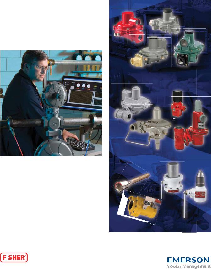
Fisher® LP-Gas Equipment
Global Technology Leadership
Our commitment to providing customers with customized solutions, dependable products, along with uncompromising quality standards and exceptional service is a tradition dating back to our beginnings in 1880, when William Fisher invented the fi rst regulator. Today, Fisher LP-Gas Equipment is a part of Emerson Process Management’s
Regulator Technologies Division, the World Leader in valve and regulator design and manufacturing. Emerson, a $24.4 billion company, invests over $800 million in research and development annually. Being a part of Emerson provides Fisher LP-Gas Equipment with the resources of a Global Technology Leader.
Domestic Regulators
Commercial/Industrial Regulators
Laboratory Tests Simulate Field Conditions
Commitment to the LP-Gas Industry
With a focus on Safety and Reliability, Fisher LP-Gas Equipment continues a tradition of delivering innovative, high performance products utilizing the latest technologies. From the development of the fi rst rubber diaphragm for regulators by Fisher in 1928 to the development of the fi rst true internal valve in 1959, we proudly continue this tradition by introducing our new line of Jet Bleed InternalTM Valves, as well as our expanded line of commercial service regulators, providing the broadest line of regulator products offered in the LP-Gas industry today.
Commitment to our Customers
In addition to continually developing improved products for our |
Bulk Storage and Transportation Equipment |
||
customers, we are active in promoting and supporting the industry. |
|
||
Through our role in world and national organizations, we continue to |
|
||
promote increased safety throughout the entire industry. |
|
||
|
|
|
|
|
|
|
|

TaBle of conTenTs
REGULATOR APPLICATION MAP . . . . . . . . . . . . . . . . . . . . . . . . . 2 VALVE APPLICATION MAP . . . . . . . . . . . . . . . . . . . . . . . . . . . . . . .4 REGULATOR SELECTION GUIDE. . . . . . . . . . . . . . . . . . . . . . . . . .6 VALVE SELECTION GUIDE . . . . . . . . . . . . . . . . . . . . . . . . . . . . . . 11 ACCESSORIES SELECTION GUIDE. . . . . . . . . . . . . . . . . . . . . . .16
RESIDENTIAL REGULATORS
TWO-STAGE SYSTEMS. . . . . . . . . . . . . . . . . . . . . . . . . . . . . . . . .23
FIRST-STAGE REGULATORS . . . . . . . . . . . . . . . . . . . . . . . . . . . .24
Types R122H and R622H
SECOND-STAGE REGULATORS. . . . . . . . . . . . . . . . . . . . . . . . . .25
Types HSRL, R222, R622, R642 and R652
Two–psi SERVICE REGULATORS . . . . . . . . . . . . . . . . . . . . . . . .26
Types R622E and R652E
INTEGRAL TWO-STAGE REGULATORS. . . . . . . . . . . . . . . . . . . .27
Types R232A and R632A
INTEGRAL TWO-PSI REGULATORS. . . . . . . . . . . . . . . . . . . . . . .28
Types R232E and R632E
AUTOMATIC CHANGEOVER REGULATORS . . . . . . . . . . . . . . . .29
Types 64SR, 749B, 803 and R130
COMMERCIAL REGULATORS
COMMERCIAL/INDUSTRIAL
HIGH-PRESSURE REGULATORS . . . . . . . . . . . . . . . . . . . . . . . . .30
Types 67CW, 67CH, 67CD, 67CN, 64, 64SR, 627, 630, 99 and 1098-EGR
COMMERCIAL LOW-PRESSURE
REGULATORS . . . . . . . . . . . . . . . . . . . . . . . . . . . . . . . .36 to 37, 40
Types CS200, CS400, CS800, 133L, 133H, 299H and 99L
COMMERCIAL SERVICE OVERPRESSURE PROTECTION . . . .38
Types CS403, CS404 and CS803
MONITOR OVERPRESSURE PROTECTION . . . . . . . . . . . . . . . .41
Types 627M, 99M and 1098
BACKPRESSURE REGULATORS/RELIEF VALVES . . . . . . . . . . .42
Types 98H, 289H, 1805 and 1808
REGULATOR ACCESSORIES . . . . . . . . . . . . . . . . . . . . . . . . . . . .43
INTERNAL VALVES
INTERNAL VALVES . . . . . . . . . . . . . . . . . . . . . . . . . . . . . . . . . . . .45
Types C404-32, C407-10, C471, C477, C483, C484 and C486 Types C804-32, C807-10, C871, C877, C883, C884, C897 and C891
INTERNAL VALVE ACCESSORIES . . . . . . . . . . . . . . . . . . . . . . . .59
P600 Series Brake Chamber Actuators
P700 Series Rotary Actuators
EMERGENCY SHUTOFF VALVES
EMERGENCY SHUTOFF VALVES . . . . . . . . . . . . . . . . . . . . . . . . .61
Types N550 and N562
Types N850 and N862
EXCESS FLOW VALVES . . . . . . . . . . . . . . . . . . . . . . . . . . . . . . . .62
Types F100, F130, F170, F190 and F202
RELIEF VALVES
INTERNAL/EXTERNAL/BULK PLANT RELIEF VALVES . . . 65 to 68
Types H110, H120, H123, H124, H125, H144, H148, H150,
H173, H174, H185, H284, H722, H733, H5114 and 63EGLP Series
GLOBE AND ANGLE VALVES . . . . . . . . . . . . . . . . . . . . . . . . . . . .69
Types N301, N310, N310F, N350, N401, N410, N410F and N450 Types N801, N810, N810F, N901, N910 and N910F
BACK CHECK VALVES. . . . . . . . . . . . . . . . . . . . . . . . . . . . . . . . . .70
Types G100, G101, G102, G104, G105, G106, G107, G109, G112, G200 and G201
HOSE END, FILLER, AND LIQUID TRANSFER VALVES . . . . . . .71
Types D138, D139, D140, D141, M455, N456, N480 and N481
BYPASS AND BACKPRESSURE VALVES. . . . . . . . . . . . . . . . . . .72
Types N100, N110 and N120
LIQUID LEVEL INDICATORS . . . . . . . . . . . . . . . . . . . . . . . . . . . . .74
Types J31, J402S, J403S, J415, J415-1 and J700
COUPLINGS AND ADAPTORS . . . . . . . . . . . . . . . . . . . . . . . . . . .75
M Series, Types P174 and P104-24
MISCELLANEOUS EQUIPMENT . . . . . . . . . . . . . . . . . . . . . . . . . .79 COMPLIANCE SYSTEMS. . . . . . . . . . . . . . . . . . . . . . . . . . . . . . . .80 CONVERSION FACTORS . . . . . . . . . . . . . . . . . . . . . . . . . . . . . . .81 INDEX . . . . . . . . . . . . . . . . . . . . . . . . . . . . . . . . . . . . . . . . . . . . . . .93
Where applicable, Fisher® brand products presented in this catalog are listed by Underwriters Laboratories (UL®). Use of these products may provide compliance with standards developed by the National Fire Protection Association’s Pamphlets
54 and 58. They may also assist in meeting guidelines established by the Department of Transportation, ASME and other third party agencies. Contact your Fisher brand LP-Gas Regulators and Equipment Distributor for assistance in determining product applications.
R
MEMBER
NPGA
National PROPANE GAS Association
1
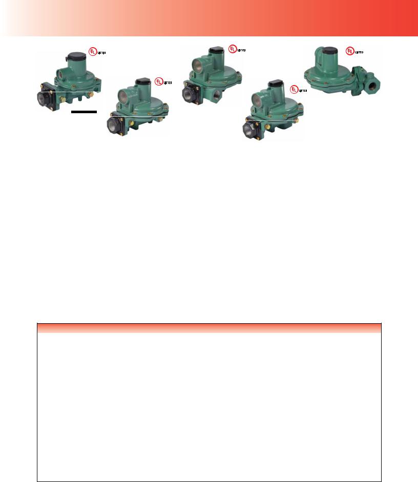
lP-gas RegulaToRs
Application: Regulators
R622
Second-
Stage
67CW
High
Pressure
Introduction
The regulator truly is the heart of an LP-Gas installation. It must compensate for variations in tank pressure from 8 to 250 psig / 0.55 to
R62
Fir
Sta
Features*
•Corrosion-Resistant and Wear-Resistant Materials
|
• |
|
|
|
|
|
|
|
|
|
|
99 |
Stainless Steel Inlet Screen |
|
|
||||||||
• Large Drip-Lip Vent |
|
|
|
||||||||
High Pressure |
|
|
|||||||||
• |
High Capacity Relief |
|
|
|
|
|
|
|
|
|
|
|
|
|
|
|
|
|
|
|
|
||
|
• |
Easy Installation |
|
|
|
|
|
|
|
|
|
|
• Improved Regulation |
|
|
|
|
|
|
|
|
|
|
|
• Built-in Gauge Taps |
|
|
|
|
|
|
|
|
|
|
|
|
|
|
|
|
|
|
|
|
|
|
*Features Vary By Model.
17.2 bar and deliver a constant outlet pressure of LP-Gas typically at 11 inches w.c. / 27 mbar
to consuming appliances. The regulator must deliver this pressure despite the intermittent use of the appliances.
In propane service, NFPA 58 requires Two-Stage regulation on all fi xed piping systems that serve
14 inches w.c. / 35 mbar appliance systems (normally operated at 11 inches w.c. / 27 mbar pressure). Two-Stage regulation produces a nearly
lP-gas RegulaToRs
constant pressure to the appliance and can result in a more effi cient LP-Gas operation for the dealer resulting in less maintenance and fewer installation call-backs.
With properly selected regulators, the internal relief valve provides 2 psig / 0.14 bar overpressure protection as required by NFPA 58.
Emerson Process Management Regulator Technologies Inc. (Regulator Technologies) is a
leading international supplier of cost-effective products, services and solutions used in the propane industry. Around the world, Regulator Technologies and its distributors offer quality products as well as applications engineering, education programs, and after sales service. For any of the products described in this catalog, contact the Fisher® LP-Gas Equipment distributor near you.
R232E |
R632A |
CS800 |
Joe™ |
|
|
 ressure
CS403
Low Pressure
High
CS404
Low Pressure 
1098
High Pressure
Fisher Regulator Color Code
First-Stage.......................................... |
Red |
Second-Stage..................................... |
Palm Green |
2-psi Service ...................................... |
White* |
Integral Two-Stage.............................. |
Gray |
Pounds to Pounds ............................... |
Red |
Industrial ............................................ |
Black or Gray |
*Types R622E and R652E are green with white closing caps
3
lP-gas ValVes
Application: Valves and Relief Valves
J 
C484-24 |
 et Bleed
  ternal™ Valve
 -24
-24
 P723
P723 
 otary
otary
 uator
uator
N550 with P539A
Pneumatic Actuator
H722
Relief Valve
C407-10 with P731
Internal Valve with
Rotary Actuator
4
lP-gas ValVes
Introduction
Fisher® brand internal valves, relief valves, emergency shutoff valves and globe and angle valves are installed in the inlets and outlets (liquid or vapor) of pressure vessels and in piping systems to control the fl ow of LP-Gas and
Anhydrous Ammonia (NH3). These valves are frequently used on bobtails, transport truck tanks, large stationary storage tanks and in-line installations.
The valves provide a means of withdrawing and fi lling product with or without pumps and compressors. These valves may be used as primary shutoff valves, excess fl ow valves and back check valves. No one offers a more complete line of LP-Gas Equipment to match your job specifi cation.
N562 Emergency
Shutoff Valve
H733
Relief Valve
C404-32
Internal Valve
with P614A
Actuator
Features*
|
• Truck Relief Valves – |
|
|
|
All Stainless Steel Construction |
|
• |
High Flow Capacities |
|
• |
Positive Shutoff Valves |
N550 with P327D |
• |
Rugged Construction |
• |
Ease of Service |
|
Emergency Shutoff Valve |
• |
Wide Range of Products for |
|
|
Varying Applications |
|
*Features Vary By Model. |
|
N410-10
Angle
Valve
G201
Back Check Valve
N310-10
Globe
Valve
5
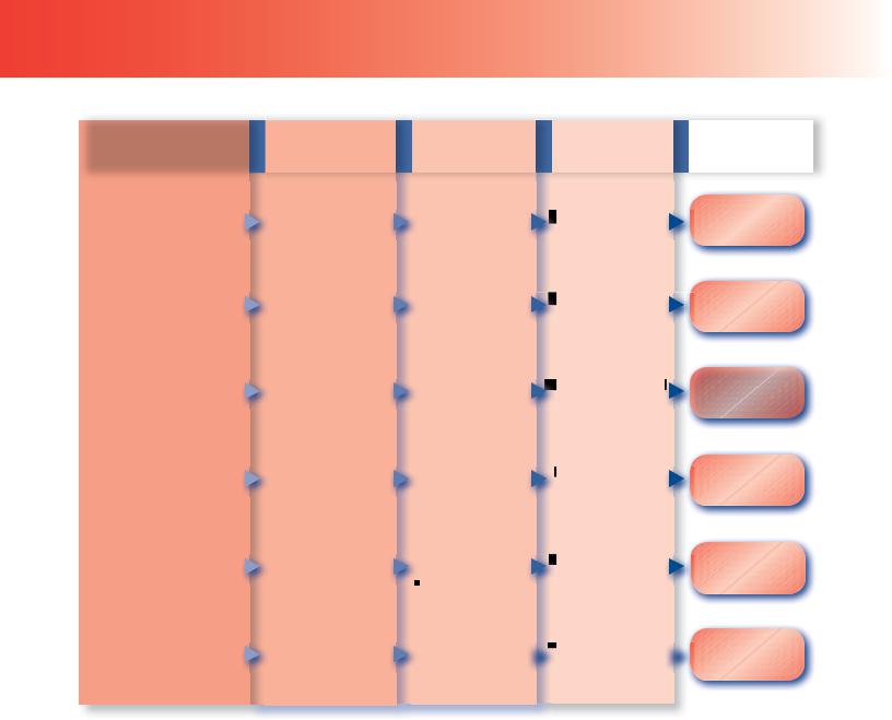
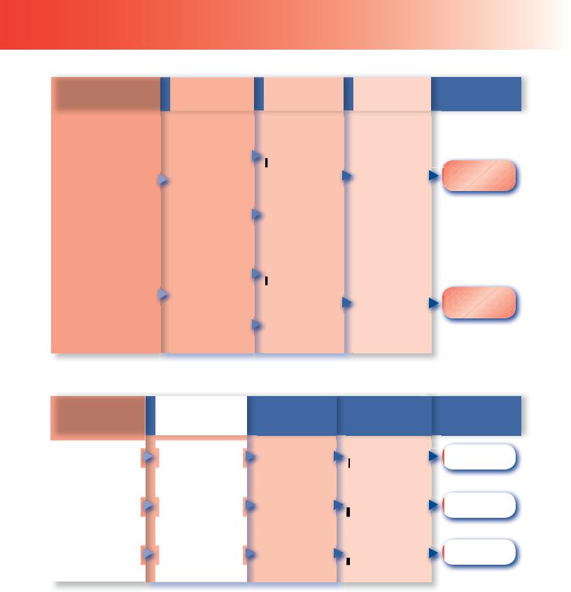
RegulaToRs QuicK selecTion guide
MAXIMUM INLET |
OUTLET |
RATED |
TYPE |
PRESSURE |
PRESSURE RANGE |
CAPACITY*(1) |
NUMBER |
|
250 psig / |
|
17.2 bar |
|
250 psig / |
|
17.2 bar |
|
250 psig / |
|
17.2 bar |
COMMERCIAL/ |
|
INDUSTRIAL |
250 psig / |
HIGH-PRESSURE |
|
REGULATORS |
17.2 bar |
|
300 psig / |
|
20.7 bar |
|
400 psig / |
|
27.6 bar |
3 to 120 psig /
0.21 to 8.3 bar
3 to 100 psig /
0.21 to 6.9 bar
5 to 40 psig /
0.35 to 2.8 bar
8 to 20 psig /
0.55 to 1.4 bar
7 inches w.c. to 65 psig /
17 mbar to 4.5 bar
3 to 100 psig /
0.21 to 6.9 bar
1.2M BTU per hour /
13.5 SCMH
5.25M BTU per hour /
59.1 SCMH
20.95M BTU per hour /
235 SCMH
14M BTU per hour /
158 SCMH
74.3M BTU per hour /
836 SCMH
1.2B BTU per hour /  13,481 SCMH
67C Series
Page 30
64 Series
Page 31
627 Series
Page 32
630 Series
Page 32
99 Series
Page 34
1098 Series
Page 35
*See capacity tables in the following sections for expanded rating information.
1.Based on inlet pressure 20 psig / 1.4 bar greater than outlet with 20% droop, unless otherwise noted.
2.Based on 2000 psig / 138 bar inlet pressure setting.
6
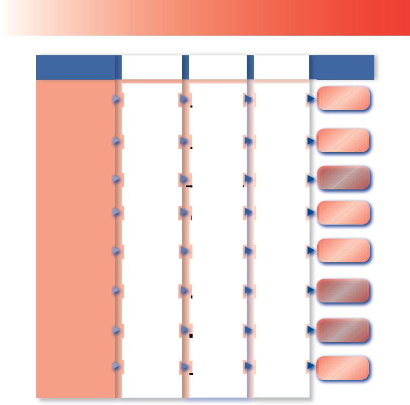
RegulaToRs QuicK selecTion guide
COMMERCIAL/ INDUSTRIAL LOW-PRESSURE REGULATORS
MAXIMUM INLET |
OUTLET |
RATED |
|
PRESSURE |
PRESSURE RANGE |
CAPACITY*(1) |
|
125 psig / |
3.5 inches w.c. |
3.9M BTU per hour / |
|
to 2 psig / |
|||
8.6 bar |
43.8 SCMH(3) |
||
|
9 mbar to 0.14 bar |
|
|
125 psig / |
3.5 inches w.c. |
8.9M BTU per hour / |
|
to 5.5 psig / |
|||
8.6 bar |
100 SCMH(2) |
||
|
9 mbar to 0.38 bar |
|
|
125 psig / |
8 inches w.c |
20M BTU per hour/ |
|
to 5.5 psig / |
|||
8.6 bar |
224 SCMH |
||
20 mbar to 0.38 bar |
|||
|
|
||
60 psig / |
1.5 to 3 psig / |
66.15M BTU per hour / |
|
4.1 bar |
0.10 to 0.21 bar |
745 SCMH(2) |
|
|
8.5 to |
70.8M BTU per hour / |
|
60 psig / |
18 inches w.c. / |
||
797 SCMH(3) |
|||
4.1 bar |
21 to 45 mbar |
||
|
|||
|
9 inches w.c. |
38M BTU per hour / |
|
150 psig / |
to 16 psig / |
||
428 SCMH |
|||
10.3 bar |
22 mbar to 1.1 bar |
||
|
|||
|
7 inches w.c. |
63.25M BTU per hour/ |
|
150 psig / |
to 5 psig / |
||
712 SCMH |
|||
10.3 bar |
18 mbar to 0.35 bar |
||
|
|||
|
3 inches w.c. |
556,000 |
|
|
BTU per hour / |
||
250 psig / |
to 5 psig / |
||
6.2 SCMH(4) |
|||
17.2 bar |
7 mbar to 0.35 bar |
|
|
|
|
|
TYPE
NUMBER
CS200 Series
Page 36
CS400 Series
Page 36
CS800 Series
Page 36
Type 133H
Page 40
Type 133L
Page 40
299H Series
Page 40
99-500P Series
Page 40
912 Series
Page 43
*See capacity tables in the following sections for expanded rating information.
1.Based on inlet pressure 20 psig / 1.4 bar greater than outlet with 20% droop, unless otherwise noted.
2.Based on 10 psig / 0.69 bar inlet pressure setting and 20% droop.
3.Based on 10 psig / 0.69 bar inlet pressure setting and 2-inches w.c. / 5 mbar droop.
4.Types 912-101 and -104 rating at 30 psig / 2.1 bar inlet.
7
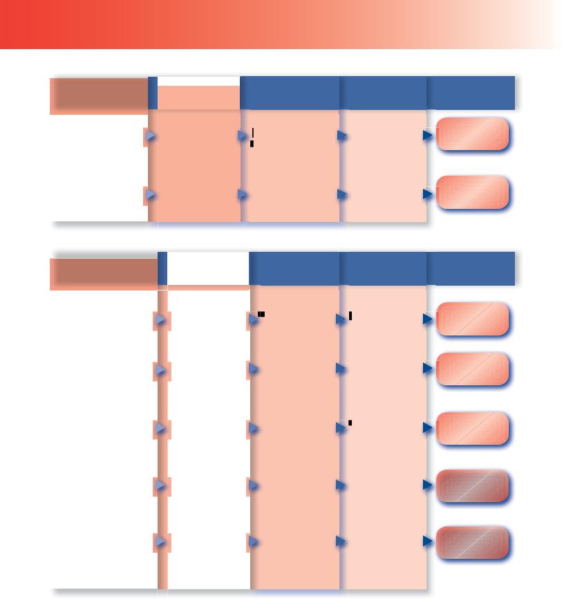
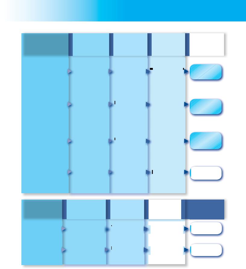
RegulaToRs QuicK selecTion guide
|
MAXIMUM INLET |
OUTLET PRESSURE |
|
PRESSURE |
SETTING/SETPOINTS |
|
|
10 psig / 0.69 bar |
|
250 psig / |
|
|
17.2 bar |
+/- 1 psig / 69 mbar |
|
|
nominal outlet setting |
FIRST-STAGE |
|
(non-adjustable) |
REGULATORS |
|
|
|
250 psig / |
5 or 10 psig / |
|
17.2 bar |
0.35 or 0.69 bar |
|
|
standard setpoints |
|
|
|
|
MAXIMUM INLET |
STANDARD |
|
|
PRESSURE |
SETPOINT |
|
|
|
|
|
|
10 psig / |
9 to 13 inches w.c. / |
|
|
0.69 bar |
||
|
22 to 32 mbar |
||
|
|
||
|
10 psig / |
11 inches w.c. / |
|
|
0.69 bar |
||
|
27 mbar |
||
|
|
||
SECOND-STAGE |
10 psig / |
11 inches w.c. / |
|
REGULATORS(3) |
0.69 bar |
||
27 mbar |
|||
|
10 psig / |
11 inches w.c. / |
|
|
0.69 bar |
27 mbar |
|
|
10 psig / |
11 inches w.c. / |
|
|
0.69 bar |
||
|
27 mbar |
||
|
|
||
|
|
|
RATED
CAPACITY*(1)
1.1M BTU per hour /
12.4 SCMH
2.4M BTU per hour /
27.0 SCMH
RATED
CAPACITY*(2)
2.6M BTU per hour /
29.3 SCMH
650,000 BTU per hour / 7.3 SCMH
1.4M BTU per hour /
15.8 SCMH
920,000 BTU per hour/ 10.4 SCMH
1M BTU per hour /
11.2 SCMH
TYPE
NUMBER
R122H Series
Page 24
R622H Series
Page 24
TYPE
NUMBER
Type HSRL
Page 25
R222 Series
Page 25
R622 Series
Page 25
R642 Series
Page 25
R652 Series
Page 25
*See capacity tables in the following sections for expanded rating information.
1.Based on 30 psig / 2.1 bar inlet pressure and 20% droop.
2.Based on 10 psig / 0.69 bar inlet pressure setting.
3.Second-Stage regulators are UL® rated.
8
RegulaToRs QuicK selecTion guide
|
MAXIMUM INLET |
STANDARD |
|
PRESSURE |
SETPOINT |
|
|
|
|
10 psig / |
2 psi / |
|
0.69 bar |
0.14 bar |
2-PSI SERVICE |
|
|
REGULATORS |
|
|
|
10 psig / |
2 psi / |
|
0.69 bar |
0.14 bar |
|
|
|
MAXIMUM INLET |
STANDARD |
PRESSURE |
SETPOINT |
|
|
INTEGRAL TWO-STAGE REGULATORS
First-Stage:
Approximately 10 psig / 0.69 bar
250 psig / (non-adjustable)
17.2 bar
Second-Stage:
11 inches w.c. /
27 mbar
First-Stage:
Approximately 10 psig / 0.69 bar
250 psig / (non-adjustable)
17.2 bar
Second-Stage:
11 inches w.c. / 27 mbar
RATED
CAPACITY*(1)
1 68M BTU per hour /
18.9 SCMH
.5M BTU per hour /
16.9 SCMH
RATED
CAPACITY*(2)
550,000 BTU per hour / 6.2 SCMH
950,000 BTU per hour / 10.7 SCMH
TYPE
NUMBER
R622E Series
Page 26
R652E Series
Page 26
TYPE
NUMBER
R232A Series
Page 27
R632A Series
Page 27
*See capacity tables in the following sections for expanded rating information.
1.Based on 10 psig / 0.69 bar inlet pressure setting and 20% droop.
2.Based on 30 psig / 2.1 bar inlet pressure setting and 2 inches w.c. / 5 mbar droop.
9
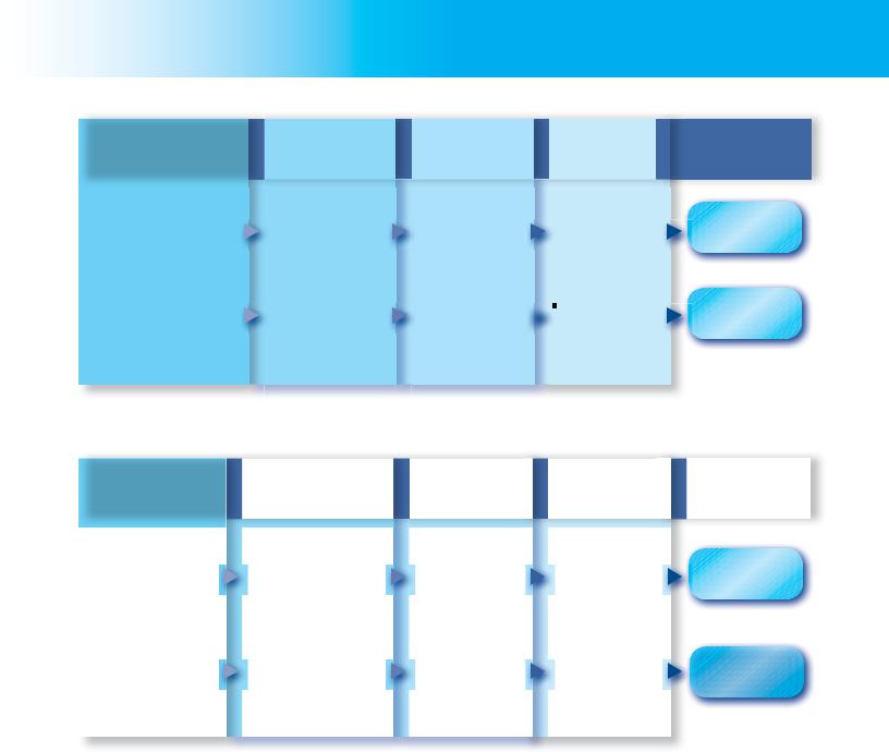
RegulaToRs QuicK selecTion guide
MAXIMUM INLET |
STANDARD |
RATED |
PRESSURE |
SETPOINT |
CAPACITY*(3) |
250 psig /
17.2 bar
INTEGRAL TWO-PSIG
REGULATORS
250 psig /
17.2 bar
|
MAXIMUM WORKING |
|
PRESSURE |
|
|
|
300 psig / |
|
20.7 bar |
BACKPRESSURE |
25 psig / |
REGULATORS/ |
|
RELIEF VALVES |
1.7 bar |
|
|
|
150 psig / |
|
10.3 bar |
|
|
First-Stage:
Approximately 10 psig / 0.69 bar (non-adjustable)
Second-Stage:
2 psi / 0.14 bar
First-Stage:
Approximately 10 psig / 0.69 bar (non-adjustable)
Second-Stage:
2 psi / 0.14 bar
RELIEF PRESSURE
SETTING
500,000 BTU per hour / 5.6 SCMH
900,000 BTU per hour / 10.1 SCMH
RELIEF
CAPACITY*
100 psig / |
93.1 GPM / |
6.9 bar |
352 l/min Propane |
15 psig / |
20,000 SCFH / |
1.0 bar |
566 SCMH Propane |
30 psig / |
12,000 SCFH / |
2.1 bar |
340 SCMH Propane |
TYPE
NUMBER
R232E Series
Page 28
R632E Series
Page 28
TYPE
NUMBER
Type 98H
Page 42
Type 289H
Page 42
Type 1805
Page 42
*See capacity tables in the following sections for expanded rating information. 3. Based on 30 psig / 2.1 bar inlet pressure setting and 20% droop.
10
ValVes and Relief ValVes QuicK selecTion guides
|
MAXIMUM INLET |
STANDARD |
CAPACITY* |
|
TYPE |
|
PRESSURE |
|
|||
|
SETPOINTS |
|
NUMBER |
||
|
(BODY RATING) |
|
|
||
|
|
|
|
|
|
|
|
|
|
|
|
INTERNAL/EXTERNAL
RELIEF VALVES
480 psig / |
|
|
85 to 375 psig / |
Up to 47,164 SCFM / |
|
||||
33.1 bar |
|
|
5.9 to 26 bar |
84,170 SCMH |
|
|
|
|
UL: Up to |
|
|
|
|
11,635 SCFM / |
480 psig / |
125 to 312 psig / |
20,764 SCMH Air |
||
33.1 bar |
|
|
8.6 to 21.5 bar |
ASME: Up to |
|
|
|
|
15,286 SCFM / |
|
|
|
|
18,097 SCMH Air |
|
|
|
|
UL: |
|
|
|
|
Up to 11,315 SCFM / |
480 psig / |
125 to 312 psig / |
19,940 SCMH Air |
||
33.1 bar |
|
|
8.6 to 21.5 bar |
ASME: |
|
|
|
|
Up to 13,876 SCFM / |
|
|
|
|
16,400 SCMH Air |
Type 63EGLP
Page 67
H282 and
H5112 Series
Page 66
H722 and
H733 Series
Page 65
420 psig / |
35 to 350 psig / |
|
2.4 to 23.8 bar |
||
29.0 bar |
||
Fixed Setting |
||
|
|
MAXIMUM WORKING |
DIFFERENTIAL / |
|
RELIEF PRESSURE |
|
|
PRESSURE |
|
|
SETTING |
|
|
|
|
|
|
|
|
300 psig / |
BYPASS AND |
20.7 bar |
|
|
BACKPRESSURE |
|
VALVES |
400 psig / |
|
|
|
27.6 bar |
50 psig / 0.83 bar  or 100 psig /
6.9 bar Setting
12 psig / 0.83 bar Setting
Up to 2456 SCFM / |
H-100 Series |
4173 SCMH |
|
|
Page 68 |
BODY SIZE AND END |
TYPE |
|
CONNECTION STYLE |
NUMBER |
|
|
|
|
1/2, 3/4, and |
98 Series |
|
1-inch FNPT |
||
|
||
|
Page 42 |
|
3/4 and |
N120 Series |
|
1-inch FNPT |
||
|
||
|
Page 73 |
|
|
|
*See capacity tables in the following sections for expanded rating information.
11
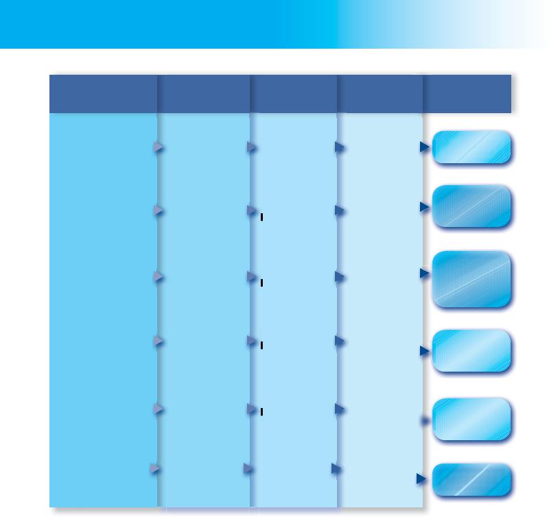
ValVes and Relief ValVes QuicK selecTion guides
PRESSURE
RATING
400 psig /
27.6 bar WOG
400 psig /
27.6 bar WOG
400 psig /
27.6 bar WOG
INTERNAL
VALVES
400 psig /
27.6 bar WOG
400 psig /
27.6 bar WOG
400 psig /
27.6 bar
EXCESS FLOW
SPRING
30 to 80 GPM /
113 to 302 l/min
60 to 460 GPM /
227 to 1741 l/min
100 to 460 GPM /
379 to 1741 l/min
160 to 400 GPM /
606 to 1514 l/min
160 to 400 GPM /
606 to 1514 l/min
340 to 1000 GPM /
1287 to
3785 l/min
TYPE CAPACITY* NUMBER
19,200 SCFH /
544 SCMH
Propane
178,000 SCFH /
5040 SCMH
Propane
178,000 SCFH /
5040 SCMH
Propane
190,000 SCFH /
5380 SCMH
Propane
190,000 SCFH /
5380 SCMH
Propane
356,200 SCFH /
10,088 SCMH
C407-10 Series
Page 46
C471-16, -24
Jet Bleed
Internal™ Series
Page 46
C477-16, -24 and
C486-24
Jet Bleed Internal™
Series
Page 46
C483-24
Jet Bleed Internal™
Series
Page 52
C484-24
 Jet Bleed Internal™
Series
Page 52
Type C404-32
Page 54
*See capacity tables in the following sections for expanded rating information.
12
ValVes and Relief ValVes QuicK selecTion guides
|
SEAT |
PRESSURE |
CAPACITY* |
|
CONSTRUCTION |
RATING |
|
|
|
||
|
|
|
|
Soft Seat and |
250 psi / |
Metal Seat |
17.2 bar |
BACK CHECK |
|
|
VALVES |
|
400 psig / |
|
Soft Seat |
|
|
27.6 bar WOG |
|
|
|
254 GPM /
961 l/min Propane
Up to 1620 GPM /  6132 l/min
Propane
TYPE
NUMBER
G100 Series
Page 70
G200 Series
Page 70
|
BODY SIZES AND END |
MAXIMUM INLET |
|
CAPACITY* |
|
TYPE |
|
CONNECTION STYLE |
PRESSURE |
|
|
NUMBER |
|
|
|
|
|
|||
|
|
|
|
|
|
|
|
1-1/4, 2, or |
400 psig / |
|
up to 850 GPM / |
N550 Series |
|
|
3-inch FNPT |
27.6 bar |
|
3127 l/min |
||
|
|
|
||||
EMERGENCY |
|
|
|
Propane |
Page 61 |
|
SHUTOFF VALVES |
|
|
|
|
|
|
|
|
|
|
|
|
|
|
|
400 psig / |
|
200 GPM / |
|
|
|
2-inch FNPT |
|
757 l/min |
N562 Series |
||
|
27.6 bar |
|
||||
|
|
|
Propane |
|
||
|
|
|
|
|
||
|
|
|
|
|
|
Page 63 |
|
|
|
|
|
|
|
*See capacity tables in the following sections for expanded rating information.
13

ValVes and Relief ValVes QuicK selecTion guides
|
SELECTION |
MAXIMUM |
|
OPERATING |
|
|
DESCRIPTION |
|
|
PRESSURE |
|
|
|
|
|
|
|
|
Globe Valve |
400 psig / |
|
(Heavy Duty |
27.6 bar |
|
Version) |
|
|
Globe Valve |
400 psig / |
|
(Economy |
|
|
27.6 bar |
|
|
Version) |
|
GLOBE AND |
|
|
|
|
|
ANGLE VALVES |
|
|
|
Angle Valve |
400 psig / |
|
(Heavy Duty |
|
|
27.6 bar |
|
|
Version) |
|
|
|
|
|
Angle Valve |
400 psig / |
|
(Heavy Duty |
|
|
27.6 bar |
|
|
Version) |
|
|
|
|
|
|
|
BODY SIZES
AND END
CONNECTION STYLES
1/2 to 3-inch FNPT
and 3-inch / DN 80 CL300 RF Flange
1/2 to 3/4-inch FNPT
1/2 to 3-inch FNPT and 3-inch / DN 80 CL300 RF Flanged
1/2 to 3/4-inch FNPT
TYPE
NUMBER
N301, N310
Series
Page 69
N350 Series
Page 69
N401,
N410 Series
Page 69
N450 Series
Page 69
*See capacity tables in the following sections for expanded rating information.
14
ValVes and Relief ValVes QuicK selecTion guides
PRODUCT/
FUNCTION
Excess Flow Valve
Filler Valve
VALVES
Hose End Valve
Bypass Valves
Cylinder Filling Valve
SELECTION
INFORMATION
Brass or Steel body in a variety of Inlet and Outlet Connection Sizes and Styles; Up to 10.7 psi / 0.74 bar differential pressure
2-inch MNPT x 2-1/4-inch ACME or 3-inch MNPT x 3-1/4-inch ACME; Single or Double Back Check style; 275 GPM / 1041 l/min filling capacity
1-3/4-inch ACME x 1-inch NPT;
Ductile iron body
1 through 2-1/2-inch FNPT; 25 to 150 psig / 1.7 to 10.3 bar Pressure range; 40 GPM / 151 l/min pumping capacity
30 psig / 2.1 bar Recommended Supply Pressure; Aluminum Body
TYPE
NUMBER
F Series
Page 64
D Series
Page 71
Type N480
Page 71
N100 Series
Page 72
Type N201
Page 79
*See capacity tables in the following sections for expanded rating information.
15
lP-gas eQuiPMenT and accessoRies
|
PRODUCT/ |
SELECTION |
TYPE |
|
FUNCTION |
INFORMATION |
NUMBER |
|
|
|
|
|
Screened Vents for |
1/4-Inch FNPT to |
Y602 Series |
|
Regulator |
1-Inch MNPT |
|
|
|
|
Page 43 |
|
Regulator Mounting |
Triangular, Bowtie, |
Type P100 |
|
or Strap Design |
||
|
Brackets |
|
|
|
|
|
|
|
|
|
Page 44 |
|
Test Pressure Gauge for |
1/4-Inch NPT or |
50 Series |
|
Appliance Line Pressure |
Female Hose |
|
|
|
||
REGULATOR |
|
|
Page 44 |
ACCESSORIES |
|
1/4-Inch MNPT; |
|
|
Pressure Gauge |
|
|
|
to 400 psi / 0 to 27.6 bar; |
J500 Series |
|
|
|
||
|
|
Ranges in |
|
|
|
MPa, kg/cm2, Bar |
Page 45 |
|
Adjustable Orifice |
Drill Size No. 80 |
Type P520L |
|
Reamer |
||
|
through No. 50 |
||
|
|
|
|
|
|
|
Page 79 |
|
|
|
|
16
lP-gas eQuiPMenT and accessoRies
BULK STORAGE TANK AND VALVE ACCESSORIES
PRODUCT/
FUNCTION
Liquid Transfer Valve
Rotary Level Gauge for Stational or Mobile Tank
Liquid Level Vent Valves
Container (Tank)
Thermometer
Female ACME
Filler Couplings
Female ACME Vapor
Return Couplings
SELECTION
INFORMATION
3/4 by 3/4-Inch MNPT
68 to 140-Inch /
1727 to 3556 mm Lengths
3/4-Inch MNPT for FNPT Connection; with or without Pressure Gauge
1/2-Inch MNPT; -40 to 120°F / -40 to 49°C
1-3/4-Inch Female ACME by 1/2-Inch MNPT through 4-1/4-Inch Female ACME by 3-Inch MNPT
1-3/4-Inch Female ACME by 3/4-Inch MNPT through 2-1/4-Inch Female ACME by 1-1/4-Inch MNPT
TYPE
NUMBER
Type M455
Page 71
Type J31
Page 74
J400 Series
Page 74
J700 Series
Page 74
Type M631
Page 75
Types M151,
M160
Page 75
17
lP-gas eQuiPMenT and accessoRies
PRODUCT/
FUNCTION
O-ring for Male
Adaptors
Adaptor Caps
BULK STORAGE |
|
TANK AND VALVE |
|
ACCESSORIES |
POL Filler Coupling |
|
Filler Valve Adaptor
SELECTION
INFORMATION
For 2-1/4 or 3-1/4-Inch Adaptors to Give a Better Seal than Washers
2-1/4 through 4-1/4-Inch Female ACME by
1-3/4 through 3-1/4-Inch Male ACME
Soft-Nose Male POL by 1/4-Inch MNPT
For Filler Valves with 1-3/4-Inch Male ACME Filler Connection and a 3/4-Inch FNPT Outlet
TYPE
NUMBER
T12655T0012 / 1H291706562
Page 75
Type M611
Page 75
Type M390
Page 75
Type M450A
Page 76
18
lP-gas eQuiPMenT and accessoRies
BULK STORAGE TANK AND VALVE ACCESSORIES
PRODUCT/ |
SELECTION |
FUNCTION |
INFORMATION |
|
|
Swivel POL Adaptor
with Metal Seats
Auxiliary Remote Cable Release for Internal Valves
Handleor Cable-Operated  Latch/Remote Release for
Internal Valves
Primary Cable Control
for Internal Valves
Cable Control, Release Mechanism, and Cable Assembly for Internal Valves
Relief Valve Pipeaway
Adaptors for DOT
Filler Hose Adaptor with Back Check Valve
Straight or Angle Male
POL by 1/4-Inch MNPT
With 25 or 50-Feet / 7.6 or 15.2 m Cable or without Cable
Built-In Fusible Link
to Close Valve in
Case of Fire
4, 5, or 6-Inch / 102, 137 or 152 mm Travel
For 1-1/4, 2, 3 and 4-Inch /  DN 32, 50, 80 and 100
Internal Valves
For Use with Types H282, H5112, H125, H150, H148 and H173 Valves
1-3/4-Inch Female ACME by 1-3/4-Inch Male ACME
TYPE
NUMBER
Type M318
Type P163A
Page 59
Type P313
Page 59
Type P650
Page 59
Type P314
Page 59
Types P104-24,
P174
Page 66
Type M570
Page 76
19
lP-gas eQuiPMenT and accessoRies
BULK STORAGE TANK AND VALVE ACCESSORIES
PRODUCT/
FUNCTION
Pneumatic Actuator
Pneumatic Actuator
Pneumatic Actuator
Pneumatic Actuator
Pneumatic Actuator
Pneumatic Actuator
SELECTION
INFORMATION
For Use with
C407-10 Series Only
For Type C484-24
Jet Bleed Internal™ Valve
For Type C483-24
Jet Bleed Internal™ Valve
For Types C471 and
C477 Jet Bleed
Internal™ Valves
(2 and 3-Inch NPT Sizes)
For Type C404-32
4-Inch / DN 100 Single
Flanged Valve
For Closing and Opening of
N550 Series Snappy Joe™
Emergency Shutoff
Valves (ESVs)
TYPE
NUMBER
Types P389
and P731
Page 60
Types P613
and P713
Page 60
Types P623
and P723
Page 60
Types P639
and P739
Page 60
Types P614A
and P714
Page 60
Type P539A
Page 61
20
lP-gas eQuiPMenT and accessoRies
BULK STORAGE TANK AND VALVE ACCESSORIES
PRODUCT/
FUNCTION
Fuse Plug
Protective Caps for Relief Valves
Seals and Plugs for Female ACME Threads
Female ACME Caps
Clamp Hose Couplings
Spanner Wrench for Large Female ACME Caps and Couplings
Ring and Chain
Assemblies
SELECTION
INFORMATION
208 to 220°F /
98 to 104°C Melting Temperature, Available in 1/8 and 1/4-inch MNPT Sizes
For Types H110 through
H174 Valves
1-1/4 to 4-1/4-Inch Male ACME
Hand or Wrench
Installation
Swivel or Standard: 1/2-Inch MNPT through 4-1/4-Inch Female ACME for 1/2 through 3-Inch Hose
For Use with 2-1/4 through 4-1/4-Inch ACME Threads
For 1-1/4 through 4-1/4-Inch ACME Caps or Dust Seals
TYPE
NUMBER
T1140399982/
T1033699982
Page 60
Type P206
Page 68
Types M178,
M535-34
Page 76
Type M108
Page 77
Type M3162
Page 78
Type P120B
Page 79
Types P147,
P167, and P183
Page 78
21

RealWorldConditions
Demand Fisher® Solutions
TYPE R232A |
TYPE R632A |
TYPE R232E |
TYPE R632E |
• FlowTestedat-40°F for Functional Performance |
• NewFull-Size2-psigModel |
• Designed to Resist Gas Impurities |
• NewCompact2-psigModel—an Industry First |
Therealworldisn’talwaysreliable.Fortunately,Fisheris. Thenew2-psigoutletmodels,TypeR632Eandtheindustry’s first 2-psig compact regulator-Type R232E, utilize a specially formulated double-diaphragm design for enhanced flow capacity at -40°F and provide greater resistance to gas impurities. The enhanced double-diaphragm design is implemented on the original integral two-stage regulators as well, creating the new and improved Types R632A and R232A regulators. With Fisher, you get real solutions and reliable performance, every time.
www.fisherregulators.com
22
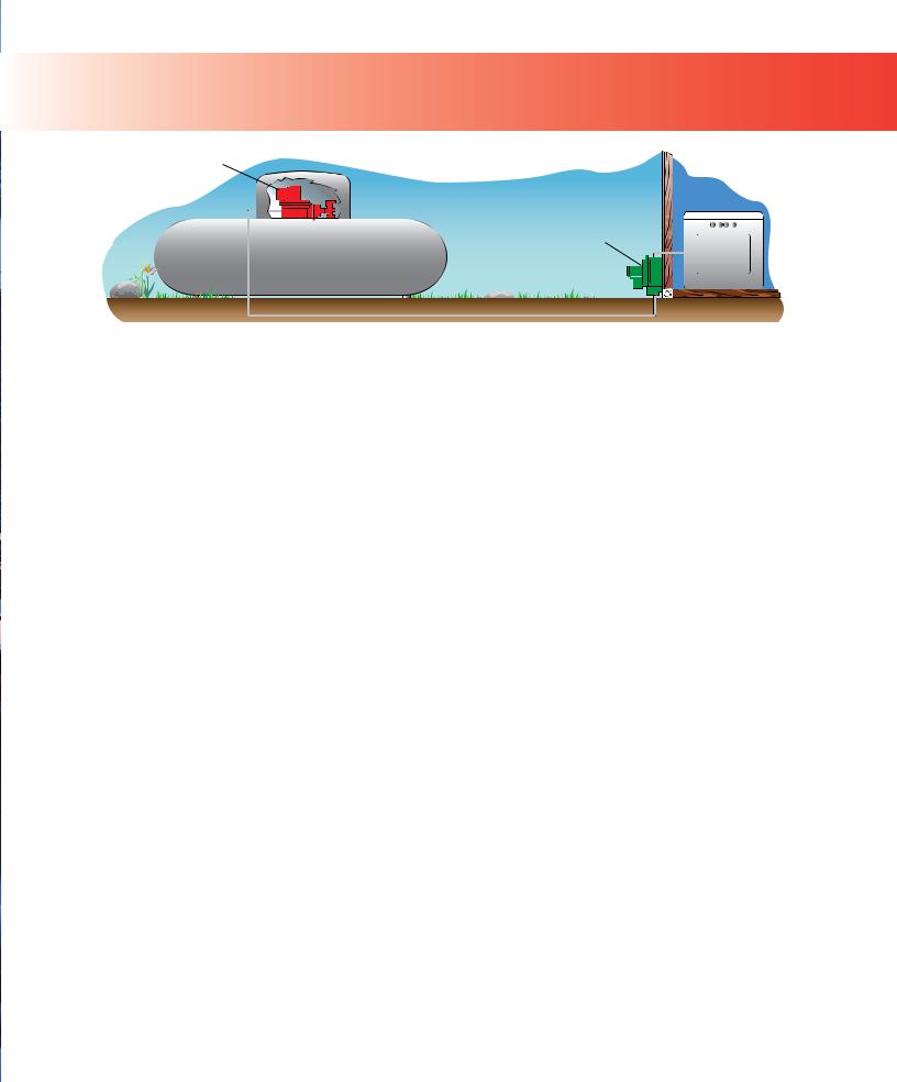
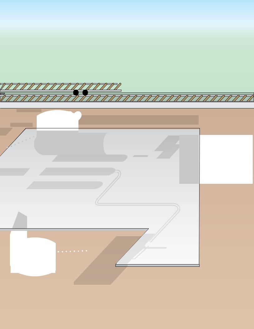
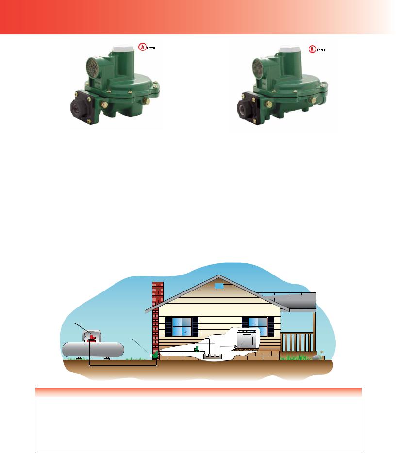
TWo-sTage sYsTeM
FIRST–STAGE REGULATOR USUALLY 10 psig /
0.69 bar
SECOND–STAGE REGULATOR 11 INCHES W.C. / 27 mbar
Figure 1. Two-Stage Regulation, One at Tank and One at Building, Reduce Pressure Down to Burner Pressure (11 inches w.c. / 27 mbar)
Two-Stage Systems
Regulator Technologies Fisher® brand makes the LP-Gas industry’s largest variety of First and Second-Stage regulators for domestic and commercial/industrial applications.
A Two-Stage system (Figure 1) uses two regulators to cut the supply pressure from the storage tank to the appliance. The Two-Stage system supplies a constant outlet pressure to the appliance. With more uniform pressure, appliances work better. Single-Stage regulators should be replaced with Two-Stage or Integral Two-Stage systems to comply with code requirements such as NFPA 58.
With a Two-Stage system, a First-Stage regulator supplies a nearly constant inlet pressure around 8 to 10 psig / 0.55 to 0.69 bar to
a Second-Stage regulator. This means the Second-Stage unit does not have to attempt to compensate for widely varying inlet pressures. Second-Stage pressure can be adjusted at the building as desired.
First-Stage Regulators
First-Stage regulators reduce tank pressure to a lower pressure (usually 10 psig / 0.69 bar) for a Second-Stage regulator. Fisher brand
First-Stage regulators are painted red for easy identifi cation. Vents are screened with standard orientation over the outlet.
Two-psi Service Regulators
Two-psi Service regulators serve as an intermediate regulator after the First-Stage regulator. These regulators are designed for
2 psig / 0.14 bar LP-Gas regulator systems. Fisher brand 2-psi regulators are painted white or are green with white closing caps for easy identifi cation.
Second-Stage Regulators
Second-Stage regulators reduce the pressure from a First-Stage unit to 11 inches w.c. / 27 mbar in domestic installations. Vents are screened with standard orientation over the inlet; however, other vent orientations are available. Fisher brand Second-Stage regulators are normally painted palm green for easy identifi cation.
Integral Two-Stage Regulators
Integral Two-Stage units combine a First-Stage regulator and Second-Stage regulator into one compact unit and are
recommended for installations where piping distance between the building being served and the tank is short. Integral Two-Stage regulators provide all the advantages of Two-Stage regulation.
These units are color coded gray for easy identifi cation. Vents are screened with standard orientation over the outlet.
Five Reasons to Two-Stage
1.Compliance with Code Requirements such as NFPA 58
2.Fewer Trouble Calls
With a Two-Stage system, one can expect fewer customer trouble calls due to regulator freeze-ups from too much water in the gas. A Two-Stage regulator reduces these possibilities in two ways:
a)a larger orifi ce can be used, making it more diffi cult for ice to build up and block the orifi ce, and
b)more heat can be transferred through the walls of two regulators than one
3.Smaller Pipe or Tubing
Due to the higher pressure between the First and Second-Stage units, smaller pipe or tubing can be used on a Two-Stage system. These savings can make a Two-Stage system more economical to install than a Single-Stage.
4. Constant Appliance Pressure
With a Two-Stage system, a First-Stage regulator supplies a nearly constant inlet pressure of 8 to 10 psig / 0.55 bar to 0.69 bar to a Second-Stage regulator. This means that the Second-Stage
regulator does not have to attempt to compensate for widely varying inlet pressures. With more uniform pressure, appliances work better and customers are less likely to experience problems that result in service calls.
5. Keep Downstream Pressure Below 2 psig / 0.14 bar
Second-Stage and Integral Two-Stage regulators have internal pressure relief valves, which limit the outlet pressure to 2 psig /
0.14 bar when the seat disc is removed and the inlet pressure is 10 psig / 0.69 bar or less as specifi ed in UL 144, STANDARD
FOR LP-GAS REGULATORS.
When to Two-Stage
Two-Stage systems whenever the following conditions exist:
1.Compliance with regulation codes.
2.There is a possibility of moisture in the LP-Gas.
3.Wide fl uctuations in gas demand exist.
4.Winter and summer temperatures vary greatly.
23
First-stage regulators
TYPE R122H
Types R122H and R622H First-Stage Regulators are Underwriters
Laboratories (UL®) listed regulators designed for Two-Stage
LP-Gas Regulator systems. These First-Stage regulators reduce tank pressure to a lower pressure (usually 10 psig / 0.69 bar) for a
Second-Stage regulator. Fisher® brand First-Stage regulators are painted red for easy identifi cation. Vents are screened with standard orientation over the outlet. The Types R122H and R622H regulators have a temperature rating of -20 to 160°F / -29 to 71°C, but have passed Fisher internal testing for lockup, relief start-to-discharge and reseal down to -40°F / -40°C.
Type R122H – Designed for use as a First-Stage regulator for domestic applications, the Type R122H’s size makes it perfect for tight installations. Stainless steel internal parts and corrosion resistant coatings provide a recommended replacement life of 20 years. Its non-adjustable setpoint makes the unit virtually tamper proof. Inlet and outlet gauge taps allow easy system testing. Large inlet and outlet wrench fl ats provide for easy installation, even in underground tanks.
The outlet pressure setpoint remains at a nominal factory setting of 10 psig / 0.69 bar. The designs superior relief performance exceeds
 22H
22H
UL requirements and provides double failure overpressure protection when used with R600 Series Second-Stage regulator. The unit’s
Fluorocarbon (FKM) valve disc provides better lockup performance and durability in contaminated gas. The vent is with
3/8-inch NPT for easy installation of vent piping. A large fabricreinforced diaphragm provides accurate regulation. The large orifi ce assists in minimizing freeze problems.
Type R622H – Time proven design constructed of corrosionresistant and wear-resistant materials, the Type R622H is designed to provide a recommended replacement life of 20 years. Built-in 1/8-inch FNPT gauge taps on both the inlet and outlet pressure sides allow for easy system checks. A large 3/4-inch FNPT drip-lip vent reduces the chance of blockage by freezing rain or sleet when properly installed with the vent pointing down. Each Type R622H is equipped for overpressure protection with a corrosion-resistant internal relief valve that provides high capacity relief and a travel stop on the closing cap. Its size and confi guration make it ideal for under-the-dome installations.
First-Stage Regulators
|
CAPACITIES (PROPANE) |
(1)(3) |
INLET |
OUTLET |
OUTLET |
OUTLET |
|
|||
|
|
ADJUSTMENT RANGE |
PRESSURE SETTING |
|||||||
TYPE NUMBER |
|
|
|
CONNECTION, |
CONNECTION, |
|
|
|
|
|
|
BTU / hour |
SCMH |
INCH |
INCH |
psig |
bar |
psig |
|
bar |
|
|
|
|
|
|||||||
|
|
|
|
|
|
|
|
|
|
|
R122H-AAJ |
|
|
|
|
|
|
|
|
|
|
|
1,100,000 |
12.4 |
1/4 FNPT |
1/2 FNPT |
Non-Adjustable |
10 |
|
0.69 |
||
R122H-AAJXB(2) |
|
|||||||||
|
|
|
|
|
|
|
|
|
|
|
|
|
|
|
|
|
|
|
|
|
|
R622H-BGK |
|
|
|
1/2 FNPT |
|
|
|
|
|
|
|
2,000,000 |
22.5 |
|
1/2 FNPT |
4 to 6 |
0.28 to |
5 |
|
0.34 |
|
R622H-HGK |
FPOL |
|
||||||||
|
|
|
|
|
||||||
|
|
|
|
0.41 |
|
|||||
|
|
|
|
|
|
|
|
|
|
|
|
|
|
|
|
|
|
|
|
|
|
R622H-JGK |
2,250,000 |
25.3 |
FPOL |
3/4 FNPT |
|
|
|
|
|
|
|
|
|
|
|
|
|
|
|
|
|
R622H-BGJ |
2,100,000 |
23.6 |
1/2 FNPT |
1/2 FNPT |
|
|
|
|
|
|
|
|
|
|
|
|
|
|
|
|
|
R622H-DGJ |
2,400,000 |
27.0 |
3/4 FNPT |
3/4 FNPT |
|
0.55 to |
|
|
|
|
|
|
|
|
|
|
8 to 12 |
10 |
|
0.69 |
|
R622H-HGJ |
2,100,000 |
23.6 |
|
1/2 FNPT |
0.83 |
|
||||
|
|
|
|
|
||||||
|
|
|
|
|
|
|||||
|
|
|
|
FPOL |
|
|
|
|
|
|
R622H-JGJ |
2,250,000 |
25.3 |
3/4 FNPT |
|
|
|
|
|
||
|
|
|
|
|
|
|||||
|
|
|
|
|
|
|
|
|
|
|
1.Based on 30 psig / 2.1 bar inlet pressure and 20% droop.
2.Vent over gauge taps.
3.Metric conversion is based on 2516 BTU/ft3 of gas at 60°F / 16°C.
24
seCond-stage regulators
TYPE HSRL
TYPE R642
TYPE R622 |
TYPE R652 |
Types R222, R622, R642, R652 and HSRL Second-Stage regulators are Underwriters Laboratories (UL®) listed regulators designed to reduce the outlet pressure from a First-Stage regulator, usually 10 psig / 0.69 bar to 11 inches w.c. / 27 mbar, in domestic installations. Vents are screened with standard orientation over the inlet, but other orientations are available. Fisher® brand Second-
Stage regulators are painted palm green for easy identifi cation.
Types R222, R622, R642 and R652 are equipped with a stainless steel inlet screen to reduce the amount of debris entering the regulator and have a temperature rating of -20 to 160°F / -29
to 71°C, but have passed Fisher internal testing for lockup, relief start-to-discharge and reseal down to -40°F / -40°C.
Type R222 is designed for small domestic applications up to 650,000 BTU per hour / 7.3 SCMH. The unit provides the same features as the Type R622 in a smaller package and its design provides a recommended replacement life of 20 years.
Type R622 is designed for Two-Stage domestic applications up to 1,400,000 BTU per hour / 15.8 SCMH. The Type R622’s time proven design and corrosion resistant materials, provide a recommended replacement life of 20 years.
Type R622 contains a high performance relief valve and a large
3/4-inch screened vent to limit downstream pressure to less than
2 psig / 0.14 bar in an overpressure situation as required by NFPA 58.
The relief valve design exceeds the industry standard by limiting the downstream pressure to 2 psig / 0.14 bar even in a double failure situation when used with a Type R622H or R122H First-Stage regulator. The Type R622 is adjustable from 9 to 20 inches w.c. / 22 to 50 mbar.
For easy system checks, the Type R622 has 1/8-inch NPT built-in gauge taps orifi ced to a No. 54 drill size, on both the upstream and downstream sides. This regulator also features a large 3/4-inch driplip vent design.
Types R642 and R652 are designed for domestic applications up to 920,000 / 10.4 and 1,000,000 BTU per hour / 11.3 SCMH, respectively. These units provide all the same features as the
Type R622, including the 20-year recommended replacement life and double failure protection, in an angle body for the Type R642 and backmounted design for the Type R652.
Type HSRL is an UL listed regulator designed for light commercial applications up to 2,600,000 BTU per hour / 29.3 SCMH. It utilizes a high strength cast iron body and a 3/4-inch NPT drip lip vent design. The PFC and SFC feature an angle-body design. The design also includes a high capacity internal relief valve and a 20-year recommended replacement life.
Second-Stage Regulators
|
CAPACITIES (PROPANE)(1) |
INLET |
OUTLET |
OUTLET |
OUTLET |
||||
TYPE NUMBER |
|
|
CONNECTION, |
CONNECTION, |
PRESSURE RANGE |
PRESSURE SETTING |
|||
|
BTU / hour |
SCMH |
INCH |
INCH |
Inch w.c. |
mbar |
Inch w.c. |
|
mbar |
|
|
|
|
||||||
|
|
|
|
|
|
|
|
|
|
R222-BAF |
650,000 |
7.3 |
1/2 FNPT |
1/2 FNPT |
9.5 to 13 |
24 to 32 |
|
|
|
|
|
|
|
|
|
|
|
|
|
R622-BCF |
875,000 |
9.8 |
1/2 FNPT |
1/2 FNPT |
|
|
|
|
|
|
|
|
|
|
|
|
|
|
|
R622-CFF |
1,400,000 |
15.8 |
1/2 FNPT |
|
|
|
|
|
|
|
|
|
|
|
|
|
|
||
R622-DFF |
3/4 FNPT |
|
9 to 13 |
22 to 32 |
11 / 27 |
|
|||
|
|
|
|
||||||
|
|
|
|
|
|
|
|||
R642-DFF |
920,000 |
10.4 |
3/4 FNPT |
|
|
|
|||
|
|
|
|
|
|
||||
|
|
|
|
|
|
|
|
|
|
R652-CFF |
1,000,000 |
11.3 |
1/2 FNPT |
|
|
|
|
|
|
|
|
|
|
|
|
|
|
||
R652-DFF |
3/4 FNPT |
|
|
|
|
|
|
||
|
|
|
|
|
|
|
|
||
|
|
|
|
|
|
|
|
|
|
R622-CFGXA |
1,125,000 |
12.7 |
1/2 FNPT |
3/4 FNPT |
13 to 20 |
32 to 50 |
18 / 45 |
|
|
|
|
|
|
|
|
|
|
|
|
HSRL-BFC |
2,300,000 |
25.9 |
3/4 FNPT |
3/4 FNPT |
|
|
|
|
|
|
|
|
|
|
|
||||
HSRL-PFC |
9 to 13 |
22 to 32 |
11 / 27 |
|
|||||
|
|
|
|
|
|||||
|
|
|
|
|
|
||||
HSRL-CFC |
2,600,000 |
29.3 |
1 FNPT |
1 FNPT |
|
||||
|
|
|
|
|
|||||
|
|
|
|
|
|
||||
HSRL-SFC |
|
|
|
|
|
||||
|
|
|
|
|
|
|
|
|
|
|
|
|
|
|
|
|
|
|
|
1. Based on 10 psig / 0.69 bar inlet pressure and 2 inches w.c. / 5 mbar droop.
25
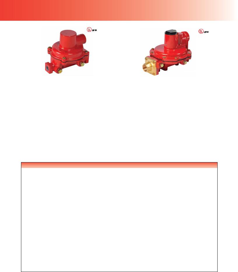
two-psi regulators
|
|
|
|
TYPE R652E |
|
TYPE R622E |
|
Types R622E and R652E, Two-psi Service Regulators, are designed for Two-psi LP-Gas Regulator Systems and listed by Underwriters Laboratories (UL®). These units are installed downstream from
a First-Stage regulator and reduce an inlet pressure of 10 psig / 0.69 bar to a nominal 2 psig / 0.14 bar outlet pressure. Two-psi Service Regulators are designed for domestic applications that supply 2 psig / 0.14 bar LP-Gas to a line regulator located inside the building. In most cases a manifold is used with corrugated stainless steel tubing (CSST) as well as other acceptable piping materials
for routing to the line pressure regulator supplying approximately 11 inches w.c. / 27 mbar to appliance regulators.
Types R622E and R652E Two-psi Service Regulators feature a combination relief valve and large vent that provide overpressure protection and exceed UL requirements. Both units have a stainless steel inlet screen to reduce the amount of debris from entering them.
Fisher® brand Types R622E and R652E are painted green with a white closing cap for easy identifi cation and have a temperature rating of -20 to 160°F / -29 to 71°C, but have passed Fisher internal testing for lockup, relief start-to-discharge and reseal down to -40°F / -40°C.
Type R622E – Time proven design constructed of corrosion resistant materials, the Type R622E is designed to provide a recommended replacement life of 20 years. Fisher brand’s fabricreinforced diaphragm and large diaphragm area provide accurate regulation at increased capacities. All components provide superior resistance to fi eld conditions that may cause wear and corrosion.
Built-in 1/8-inch taps (orifi ced to a number 54-drill size) on the upstream and downstream sides allow for easy gas system checks.
Type R652E – Provides the same features as the Type R622E, includes a 20-year recommended replacement life with a back mount design.
Typical Two-psi Installation
TYPE R122H OR R622H |
10 psig / 0.69 bar |
TYPE R622E OR R652E |
2 psig / 0.14 bar |
Two-psi Service Regulators
|
CAPACITIES (PROPANE)(1) |
CONNECTIONS |
|
OUTLET |
|
OUTLET |
|||
TYPE NUMBER |
|
|
PRESSURE RANGE |
PRESSURE SETTING |
|||||
|
|
INLET X OUTLET, INCH |
|
|
|
|
|
|
|
|
BTU / hour |
SCMH |
psig |
|
bar |
psig |
|
bar |
|
|
|
|
|
||||||
|
|
|
|
|
|
|
|
|
|
R622E-BCH |
1,460,000 |
16.4 |
1/2 x 1/2 FNPT |
|
|
|
|
|
|
|
|
|
|
|
|
69 mbar to |
|
|
|
R622E-DCH |
1,680,000 |
18.9 |
|
1 to 2.2 |
|
2 |
|
0.14 |
|
3/4 x 3/4 FNPT |
|
0.15 |
|
||||||
|
|
|
|
|
|
|
|
||
R652E-DFH |
1,500,000 |
16.9 |
|
|
|
|
|
|
|
|
|
|
|
|
|
|
|||
|
|
|
|
|
|
|
|
|
|
1. Based on 10 psig / 0.69 bar inlet pressure and 20% droop.
26
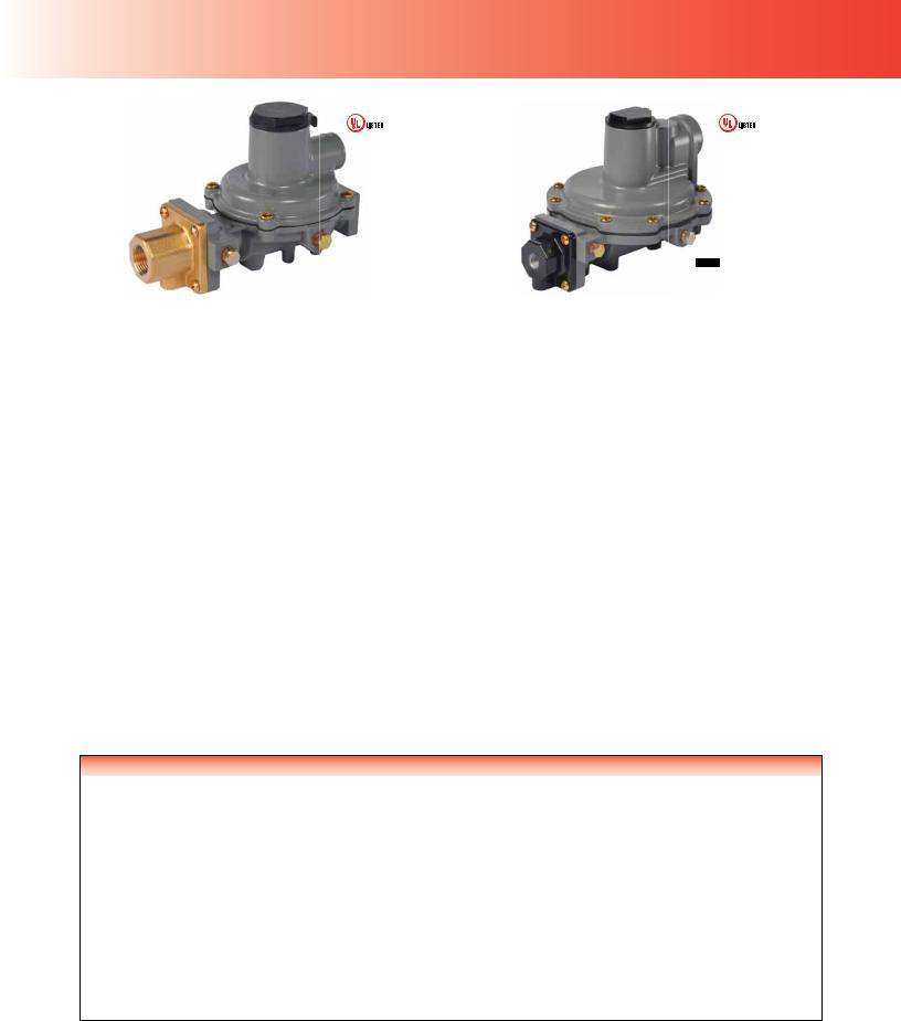
integral two-stage regulators
TYPE R232A |
R632A |
|
Integral Two-Stage regulators combine a First-Stage regulator and a Second-Stage regulator into one compact unit. Recommended for installations where piping distance is short, integral Two-Stage regulators provide all of the advantages of Two-Stage regulation (refer to page 23). Fisher® brand integral Two-Stage regulators are color coded gray for easy identifi cation. Vents are screened with standard Second-Stage vent orientation over the outlet.
The Types R632A and R232A fi rst-stage screened vent is threaded to accept a 1/4-inch OD copper tube inverted fl are with a
7/16-24 UN thread. The Types R232A and R632A have a temperature rating of -20 to 160°F / -29 to 71°C, but have passed
Fisher internal testing for lockup, relief start-to-discharge and reseal down to -40°F / -40°C.
Type R632A – is an Underwriters Laboratories (UL®) listed regulator with a capacity of up to 950,000 BTU per hour / 10.7 SCMH, recommended for on-site cylinder installations, mobile homes and domestic installations, where separation of the First and SecondStage is not cost effective. This unit offers a POL inlet connection for the easy drop-in replacement of Single-Stage regulators.
Type R632A’s high capacity relief valve and large 3/4-inch screened vent limit downstream pressure to less than 2 psig / 0.14 bar in
an overpressure situation as required by NFPA 58. Type R632A is adjustable from 9 to 13 inches w.c. / 22 to 32 mbar, with a factory setpoint of 11 inches w.c. / 27 mbar. The Type R632A features include the 20-year recommended replacement life.
Type R632A has 1/8-inch NPT built-in gauge taps orifi ced to a
No. 54 drill size, on the upstream and downstream sides. These taps provide easy access for testing the proper operation of the
First and Second-Stage while the system is pressurized. This regulator also features a large 3/4-inch drip-lip vent to reduce the chance of blockage by freezing rain or sleet when properly installed with the vent pointing down.
Type R232A – Designed for installations with small capacity loads up to 550,000 BTU per hour / 6.2 SCMH. With an overall length of 6.5 or 7 inches / 165 or 178 mm for NPT or FPOL connections respectively, this compact unit fi ts easily into confi ned spaces and is ideal for ASME tanks used on small domestic loads. Intermediate and outlet gauge taps facilitate easy system testing.
A 3/8-inch NPT vent allows easy installation of vent piping. Use of a valve stem and lever provide stable regulation and excellent durability. A large fabric-reinforced diaphragm provides accurate regulation. The large orifi ce assists in minimizing freeze problems.
Stainless steel internal and corrosion resistant coatings provide excellent corrosion resistance. The Type R232A also has the design that provides a recommended replacement life of 20 years.
Twin Cylinder Installations – The Type R232A can also be used on twin cylinder hook-ups found on travel trailers and stationary applications. These units offer a drip-lip vent style for installations without a vent protector. Proper installation requires the vent to be pointed down in a vertical position. Additional protection may be required if road splatter is a problem.
Integral Two-Stage Regulators
|
CAPACITIES (PROPANE)(1) |
INLET |
OUTLET |
OUTLET |
OUTLET |
|
|||
TYPE NUMBER |
|
|
CONNECTION, |
CONNECTION, |
ADJUSTMENT |
RANGE |
PRESSURE |
SETTING |
|
|
BTU / hour |
SCMH |
INCH |
INCH |
Inch w.c. |
mbar |
Inch w.c. |
|
mbar |
|
|
|
|
|
|
|
|
|
|
R232A-BBF |
|
|
1/4 FNPT |
|
|
|
|
|
|
R232A-BBFXA(2) |
550,000 |
6.2 |
1/2 FNPT |
9.5 to 13 |
24 to 32 |
|
|
|
|
|
|
|
|
||||||
R232A-HBF |
FPOL |
|
|
|
|||||
|
|
|
|
|
|
|
|
||
R232A-HBFXA(2) |
|
|
|
|
|
|
|
|
|
|
|
|
|
|
|
|
|
|
|
R632A-BCF |
850,000 |
9.6 |
|
1/2 FNPT |
|
|
|
|
|
R632A-BCFXA(2) |
1/4 FNPT |
|
|
11 |
|
27 |
|||
|
|
|
|
|
|
||||
R632A-CFF |
950,000 |
10.7 |
3/4 FNPT |
|
|
|
|||
|
|
|
|
|
|
||||
R632A-CFFXA(2) |
|
9 to 13 |
22 to 32 |
|
|
|
|||
|
|
|
|
|
|
|
|||
R632A-HCF |
850,000 |
9.6 |
|
1/2 FNPT |
|
|
|
||
|
|
|
|
|
|
||||
R632A-HCFXA(2) |
FPOL |
|
|
|
|
|
|||
|
|
|
|
|
|
|
|
||
R632A-JFF |
850,000 |
9.6 |
3/4 FNPT |
|
|
|
|
|
|
|
|
|
|
|
|
||||
R632A-JFFXA(2) |
|
|
|
|
|
|
|||
|
|
|
|
|
|
|
|
|
|
1.Based on 30 psig / 2.1 bar inlet pressure and 2 inches w.c. / 5 mbar droop.
2.First and Second-Stage spring case vents opposite gauge taps.
27
 Loading...