

Page 1

MMI-20020246, Rev AG
ProLink™ III with ProcessViz™ Software
Configuration, Service Tool, and Trend Graphics for
Micro Motion™ and Rosemount Flow Devices
User Manual
February 2020
Page 2

Safety messages
Safety messages are provided throughout this manual to protect personnel and equipment. Read each safety message carefully
before proceeding to the next step.
Safety and approval information
This Micro Motion product complies with all applicable European directives when properly installed in accordance with the
instructions in this manual. Refer to the EU declaration of conformity for directives that apply to this product. The EU declaration
of conformity, with all applicable European directives, and the complete ATEX Installation Drawings and Instructions are available
on the internet at www.emerson.com or through your local Micro Motion support center.
Information affixed to equipment that complies with the Pressure Equipment Directive, can be found on the internet at
www.emerson.com.
For hazardous installations in Europe, refer to standard EN 60079-14 if national standards do not apply.
Other information
Full product specifications can be found in the product data sheet. Troubleshooting information can be found in the configuration
manual. Product data sheets and manuals are available from the Micro Motion web site at www.emerson.com.
Return policy
Follow Micro Motion procedures when returning equipment. These procedures ensure legal compliance with government
transportation agencies and help provide a safe working environment for Micro Motion employees. Micro Motion will not accept
your returned equipment if you fail to follow Micro Motion procedures.
Return procedures and forms are available on our web support site at www.emerson.com, or by phoning the Micro Motion
Customer Service department.
Emerson Flow customer service
Email:
• Worldwide: flow.support@emerson.com
• Asia-Pacific: APflow.support@emerson.com
Telephone:
North and South America
United States 800-522-6277 U.K. 0870 240 1978 Australia 800 158 727
Canada +1 303-527-5200 The Netherlands +31 (0) 704 136
Mexico +41 (0) 41 7686
111
Argentina +54 11 4837 7000 Germany 0800 182 5347 Pakistan 888 550 2682
Brazil +55 15 3413 8000 Italy 8008 77334 China +86 21 2892 9000
Europe and Middle East Asia Pacific
666
France 0800 917 901 India 800 440 1468
Central & Eastern +41 (0) 41 7686
111
Russia/CIS +7 495 995 9559 South Korea +82 2 3438 4600
Egypt 0800 000 0015 Singapore +65 6 777 8211
Oman 800 70101 Thailand 001 800 441 6426
Qatar 431 0044 Malaysia 800 814 008
Kuwait 663 299 01
South Africa 800 991 390
Saudi Arabia 800 844 9564
UAE 800 0444 0684
New Zealand 099 128 804
Japan +81 3 5769 6803
2
Page 3

User Manual Contents
MMI-20020246 February 2020
Contents
Chapter 1 Before you begin............................................................................................................5
1.1 About this manual............................................................................................................................ 5
1.2 Related documentation....................................................................................................................5
1.3 Available ProLink III features per edition........................................................................................... 5
Chapter 2 Working with ProLink III ................................................................................................9
2.1 Site key and licensing........................................................................................................................9
2.2 The ProLink III interface.................................................................................................................. 14
2.3 Explore ProLink III software.............................................................................................................15
2.4 Enable inventory reset.................................................................................................................... 16
2.5 Search in ProLink III ........................................................................................................................ 16
2.6 Show Help for software interface options....................................................................................... 17
2.7 Use ProcessViz................................................................................................................................18
Chapter 3 Connect to one or more devices................................................................................... 19
3.1 Connect to a device........................................................................................................................ 19
3.2 Default communication values....................................................................................................... 21
3.3 Make an additional device connection............................................................................................23
3.4 Use the guided connection wizard..................................................................................................24
3.5 Device wiring terminals for ProLink III connections......................................................................... 24
3.6 Troubleshoot a device connection..................................................................................................29
3.7 Work with one device when several are connected.........................................................................30
3.8 View the device status and alerts....................................................................................................30
3.9 Disconnect from a device............................................................................................................... 31
Chapter 4 Use configuration data.................................................................................................33
4.1 Configuration data transfer between devices................................................................................. 33
4.2 Save a device configuration............................................................................................................ 33
4.3 Restore or load a configuration file................................................................................................. 34
4.4 Import data from a previous version of ProLink...............................................................................34
4.5 Configure a device offline............................................................................................................... 35
4.6 Print a configuration report............................................................................................................ 36
4.7 Restore the factory configuration................................................................................................... 36
Chapter 5 Use the process variables view..................................................................................... 37
5.1 Set up the process variables view....................................................................................................37
5.2 Reset totals.................................................................................................................................... 39
Chapter 6 Monitor the process, device, or device health...............................................................41
6.1 Monitor process trends...................................................................................................................41
6.2 Create data logs............................................................................................................................. 43
User Manual iii
Page 4

Contents User Manual
February 2020 MMI-20020246
6.3 Compare multiple devices.............................................................................................................. 46
iv Micro Motion ProLink III
Page 5

User Manual Before you begin
MMI-20020246 February 2020
1 Before you begin
1.1 About this manual
This user manual explains how to navigate and use:
• The Emerson Flow ProLink III software, v4.5 or later
• The ProcessViz software, v2.0 or later
This document assumes that users are familiar with the Microsoft® Windows operating
system.
For detailed information on configuring and using device-specific or application-specific
features, see the appropriate configuration and use manual. If you need additional help,
contact customer support.
1.2 Related documentation
You can find all product documentation on the product documentation DVD shipped with
the product or at www.emerson.com.
See any of the following documents for more information:
• Micro Motion ProLink III Software Product Data Sheet
• Micro Motion ProcessViz Software Product Data Sheet
• Micro Motion ProLink III Quick Start Guide
1.3 Available ProLink III features per edition
ProLink III is available in two editions: Basic and Professional for either Micro Motion or
Rosemount Flow. Depending on the edition you purchased, you have specific features
enabled.
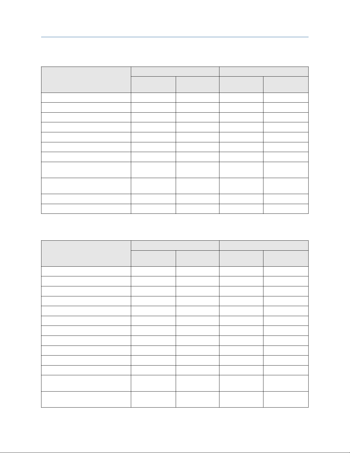
Table 1-1: ProLink III Micro Motion Basic and Professional features per edition
Feature Basic Professional
Coriolis
transmitters
Alert notification ✓ ✓ ✓ ✓
Alert resolution guide ✓ ✓ ✓ ✓
Data logging ✓ ✓
Density and
viscosity meters
Coriolis
transmitters
Density and
viscosity meters
Device simulation ✓ ✓
Diagnostics/inputs/outputs display ✓ ✓ ✓ ✓
Full device configuration ✓ ✓ ✓ ✓
Guided process support tools ✓ ✓
User Manual 5
Page 6
Before you begin User Manual
February 2020 MMI-20020246
Table 1-1: ProLink III Micro Motion Basic and Professional features per edition (continued)
Feature Basic Professional
Coriolis
transmitters
Known density verification launch ✓ ✓
Known density verification reports ✓ ✓
Load and save the device configuration ✓ ✓ ✓ ✓
Modbus®/TCP support ✓ ✓ ✓ ✓
Multidevice comparison tool ✓ ✓
Offline configuration management ✓ ✓
Print Configuration ✓ ✓
Process variable trending (one or more
devices)
ProcessViz (displays logged data files
that can be opened using ProcessViz)
Smart Meter Verification™ launch ✓ ✓
Smart Meter Verification reports
(1) Requires a Smart Meter Verification Pro license
(1)
✓ ✓
Density and
viscosity meters
Coriolis
transmitters
✓ ✓
✓ ✓
Density and
viscosity meters
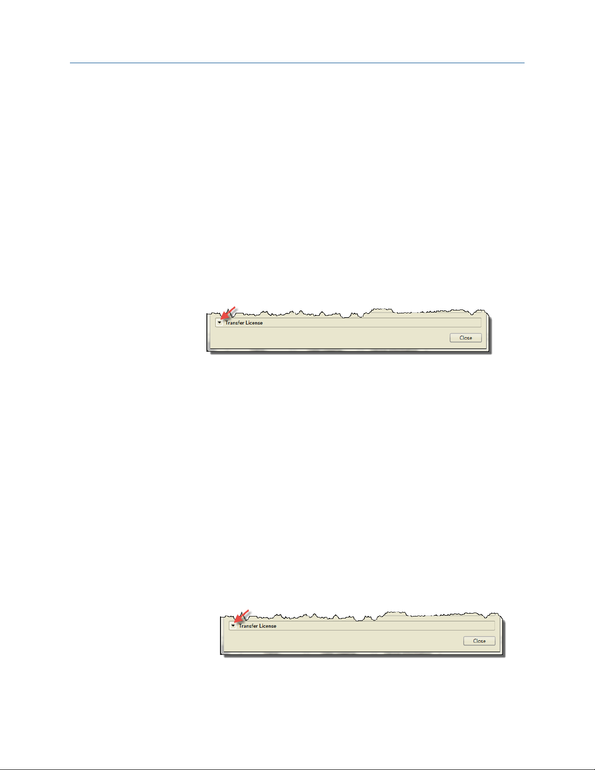
Table 1-2: ProLink III Rosemount Flow Basic and Professional features per edition
Feature Basic Professional
Magmeter
transmitters
Alert notification ✓ ✓ ✓ ✓
Alert resolution guide ✓ ✓ ✓ ✓
Data logging ✓ ✓
Device simulation ✓ ✓
Diagnostics/inputs/outputs display ✓ ✓ ✓ ✓
Filter visualization tool ✓
Full transmitter configuration ✓ ✓ ✓ ✓
Guided process support tools ✓ ✓
Load and save the device configuration ✓ ✓ ✓ ✓
Multidevice comparison tool ✓ ✓
Offline configuration management ✓ ✓
Process variable trending (one or more
devices)
ProcessViz (displays logged data files
that can be opened using ProcessViz)
Vortex
transmitters
Magmeter
transmitters
✓ ✓
✓ ✓
Vortex
transmitters
6 Micro Motion ProLink III
Page 7

User Manual Before you begin
MMI-20020246 February 2020
Table 1-2: ProLink III Rosemount Flow Basic and Professional features per edition (continued)
Feature Basic Professional
Magmeter
transmitters
Smart Meter Verification launch ✓ ✓
Smart Meter Verification reports ✓
Vortex
transmitters
Magmeter
transmitters
Vortex
transmitters
User Manual 7
Page 8

Before you begin User Manual
February 2020 MMI-20020246
8 Micro Motion ProLink III
Page 9

User Manual Working with ProLink III
MMI-20020246 February 2020
2 Working with ProLink III
2.1 Site key and licensing
2.1.1 Obtain a site key for ProLink III and ProcessViz
You will need to obtain and enter a site key to validate a license for the ProLink III
Professional edition and ProcessViz.
Software Basic edition Professional edition
ProLink III ProLink III Basic does
not require a license.
ProcessViz Not available If ProcessViz was purchased, available with a
Procedure
1. Start ProLink III to obtain a ProLink III license or ProcessViz to obtain a ProcessViz
license.
ProLink III
In the ProLink III start-up screen, choose File
→ License.
• Available with a generated temporary
license that is active for seven days
• Requires a permanent license after seven
days
Important
Obtain the site key before the temporary license
expires. Once the trial period completes, you
will not be able to use ProLink III.
separate site key for ProcessViz in addition to a
site key for ProLink III.
ProcessViz
a. On the first ProcessViz screen, select
the ProcessViz icon in the upper left
corner.
b. Choose License….
2. Enter your serial number in the Serial Number field.
3. Select Get Site Key.
The Site Key field is automatically populated.
4. Select Validate.
User Manual 9
Page 10
Working with ProLink III User Manual
February 2020 MMI-20020246
2.1.2 Transfer an existing license for ProLink III
Both the ProLink III temporary license and permanent license are keyed to a specific disk
and specific folder or directory on your computer. You can move the ProLink III installation
to a different folder on the same computer, or to a different computer. For additional
information on transferring an existing license, contact customer support at
www.emerson.com.
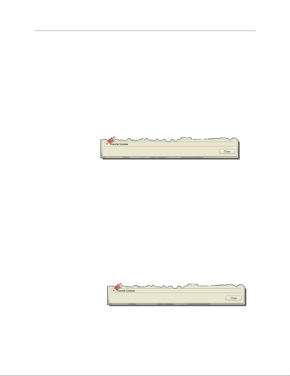
2.1.2 Transfer ProLink III to another location on the same computer
Procedure
1. Choose File → License.
2. Select the down arrow next to Transfer License.
Example
3. Select To Directory.
4. Specify the directory where ProLink III will be transferred.
5. Install ProLink III in this new directory.
2.1.2 Transfer ProLink III from one computer to another
Procedure
1. Go to the target computer (the computer where you are transferring the license)
and do the following steps.
a) Install ProLink III, but when it asks to make a temporary license, select
Cancel.
For installation instructions, see the Micro Motion ProLink III Quick Start Guide.
b) Start ProLink III.
c) Choose File → License.
d) Select the down arrow next to Transfer License.
Example
e) Select Into Computer.
The location window pops up.
10 Micro Motion ProLink III
Page 11

User Manual Working with ProLink III
MMI-20020246 February 2020
f) Select a storage location [CD-RW, DVD, USB Flash, or Floppy (real or image
file)].
ProLink III writes a system transfer file to the storage device.
g) Insert the storage device when requested.
A success message pops up when the transfer is complete.
h) Disconnect the storage device.
2. Go to the source computer (the computer with the original ProLink III license) and
do the following steps.
a) Insert the storage device.
b) Start ProLink III.
c) Choose File → License.
d) Select the down arrow next to Transfer License.
e) Select Out of Computer.
The location window pops up.
f) Select the storage location [CD-RW, DVD, USB Flash, or Floppy (real or image
file)].
• ProLink III adds two more system transfer files to the storage device.
• A success message pops up when the transfer is complete.
g) Disconnect the storage device.
The license window will not display No License until you close the window
and then reopen it.
3. Go to the target computer (the computer where you are transferring the license)
and do the following steps.
a) Insert the storage device.
b) Start ProLink III.
c) Choose File → License.
d) Click the down arrow next to Transfer License.
e) Select Into Computer.
• ProLink III copies the license to the new installation and deletes all three
system transfer files.
• A success message pops up when the transfer is complete.
• The license window refreshes and shows activated. The window will not
show the original serial number.
f) Close ProLink III and install any upgrades.
User Manual 11
Page 12
Working with ProLink III User Manual
February 2020 MMI-20020246
2.1.3 Transfer an existing license for ProcessViz
The ProcessViz license is keyed to a specific disk and specific folder or directory on your
computer. You can move the ProcessViz installation to a different folder on the same
computer, or to a different computer. For additional information on transferring an
existing license, contact customer support at www.emerson.com.
2.1.3 Transfer ProcessViz to another location on the same computer
Procedure
1. Select the down arrow next to Transfer License.
Example
2. Select License…
3. Select To Directory.
4. Specify the directory where ProcessViz will be transferred.
5. Install ProcessViz in this new directory.
2.1.3 Transfer ProcessViz from one computer to another
Procedure
1. Go to the target computer (the computer where you are transferring the license)
and do the following steps.
a) Install ProLink III and run it, but when it asks to make a temporary license,
select Cancel.
For installation instructions, see the Micro Motion ProLink III Quick Start Guide.
b) Start ProcessViz.
c) Select the down arrow next to Transfer License.
Example
d) Select License…
e) Select Into Computer.
The location window pops up.
12 Micro Motion ProLink III
Page 13

User Manual Working with ProLink III
MMI-20020246 February 2020
f) Select a storage location [CD-RW, DVD, USB Flash, or Floppy (real or image
file)].
The software writes a system transfer file to the storage device.
g) Insert the storage device when requested.
A success message pops up when the transfer is complete.
h) Disconnect the storage device.
2. Go to the source computer (the computer with the original ProcessViz license) and
do the following steps.
a) Insert the storage device.
b) Start ProcessViz.
c) On the first ProcessViz screen, select the ProcessViz icon in the upper left
corner.
d) Select License…
e) Select Out of Computer.
The location window pops up.
f) Select the storage location [CD-RW, DVD, USB Flash, or Floppy (real or image
file)].
• ProcessViz adds two more system transfer files to the storage device.
• A success message pops up when the transfer is complete.
g) Disconnect the storage device.
The license window will not display No License until you close the window
and then reopen it.
3. Go to the target computer (the computer where you are transferring the license)
and do the following steps.
a) Insert the storage device.
b) Start ProcessViz.
c) On the first ProcessViz screen, select the ProcessViz icon in the upper left
corner.
d) Select License…
e) Select Into Computer.
• ProcessViz copies the license to the new installation and deletes all three
system transfer files.
• A success message pops up when the transfer is complete.
• The license window refreshes and shows activated. The window will not
show the original serial number.
f) Close ProcessViz and install any upgrades.
User Manual 13
Page 14
A B C
E
Working with ProLink III User Manual
February 2020 MMI-20020246
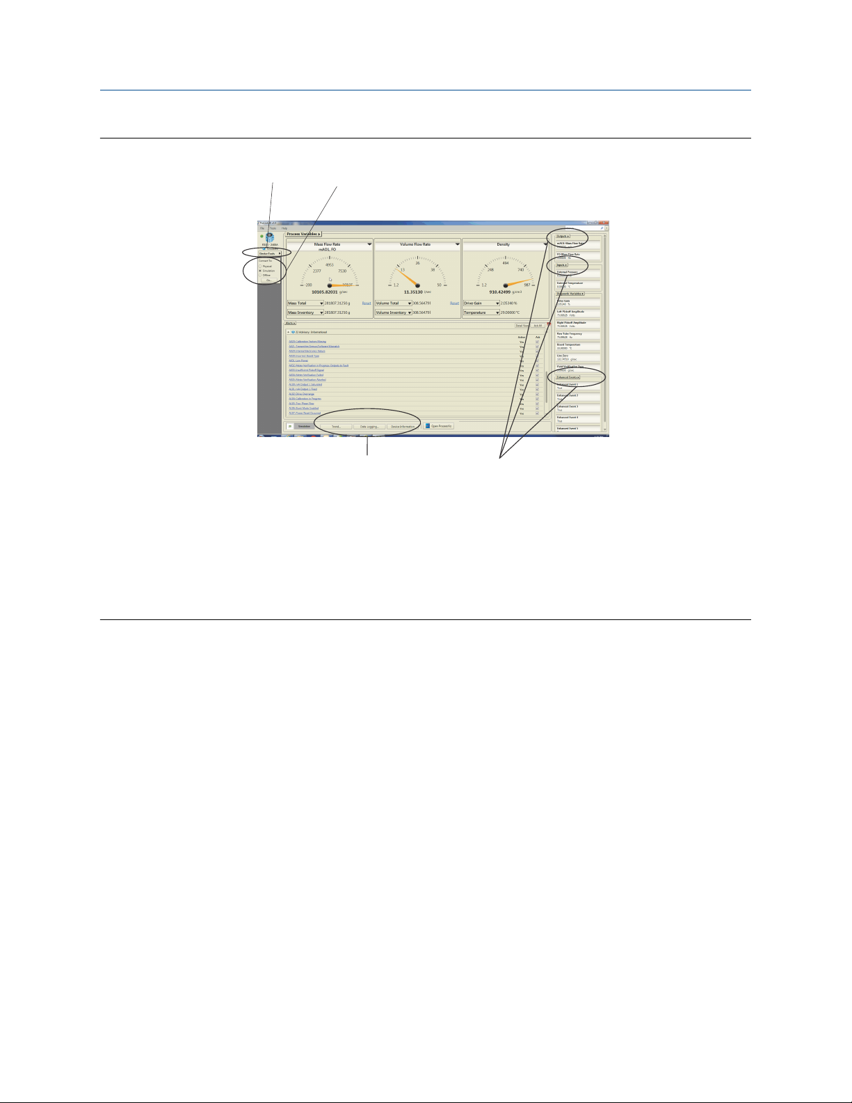
2.2 The ProLink III interface
See Figure 2-1 and Figure 2-2 for a quick reference to the information and tools available in
ProLink III.
Tip
To view and navigate ProLink III without a physical device connection, you can simulate a
device. This feature allows you to become more familiar with the interface and the
different options available for use. See Explore ProLink III software for more information.
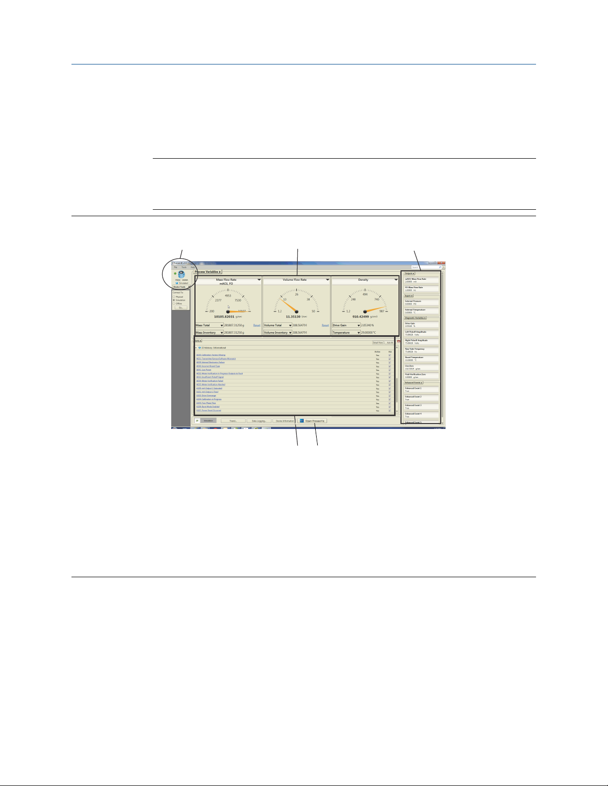
Figure 2-1: Viewing process performance on the ProLink III main screen
A. Display the transmitter type, address, and alarm status for each connected device, simulated configuration,
or offline configuration.
B. Provide quick access to your process measurements.
C. Easily view other process measurements, diagnostic variables, and have quick access to view and change the
configured settings.
D. View active alerts for the connected device, and easily view recommended actions for troubleshooting each
alert.
E. Access the ProcessViz software from ProLink III. The ProcessViz button is active (enabled) only if ProcessViz is
installed and licensed.
14 Micro Motion ProLink III
Page 15
A
B
CD
User Manual Working with ProLink III
MMI-20020246 February 2020
Figure 2-2: Navigating menus on the ProLink III main screen
A. The Device Tools menu is the main point of access to all configuration options available for each connected
device, simulated configuration, or offline configuration.
B. The Connect To options allow you to easily connect to another device or open a simulated or offline
configuration.
C. Additional access to configuring specific parameters is available through the field menus provided at the
various process views.
D. Quick access to the monitoring options is available from the main screen.
2.3 Explore ProLink III software
In ProLink III, you can simulate device connections to view and navigate the software
interface without a physical device connection.
Procedure
1. To use device simulation, do one of the following:
• From the start-up screen, select Simulate Device.
• From the main screen, select Simulation under Connect To, and select Go.
2. In Device Type, select a type of device.
3. Select Connect.
User Manual 15
Page 16

A
Working with ProLink III User Manual
February 2020 MMI-20020246
2.4 Enable inventory reset
Inventories can be reset from ProLink III only if this function is enabled in ProLink III.
Procedure
1. Choose Tools → Options.
2. Select Reset Inventories from ProLink III.
2.5 Search in ProLink III
ProLink III provides a searching capability that allows you to find specific parameter names
within the software interface. You must be connected to a physical device or simulating a
device connection to use this feature (see Figure 2-3).
Figure 2-3: Search feature
A. The Search feature allows you to find specific features or parameters in the software
interface.
Procedure
1. Connect to or simulate a device.
2. Optional: Select the down arrow next to Search to change the search options.
You can choose to see recent searches, highlight the words you are searching for, or
search all connected devices.
16 Micro Motion ProLink III
Page 17
User Manual Working with ProLink III
MMI-20020246 February 2020
3. In Search, enter the parameter name you are searching for.
As you type your search entry, one or multiple instances of the search results are
displayed directly below the Search field. The search results display the specific
device and data item found, and provide a hyperlink to the target location where
the item exists.
Tip
If no search results display, try changing your search entry to be less specific to the
label text or item description in the software, if possible.
4. To go to the desired location in the software, click the hyperlink under Target in the
search results table.
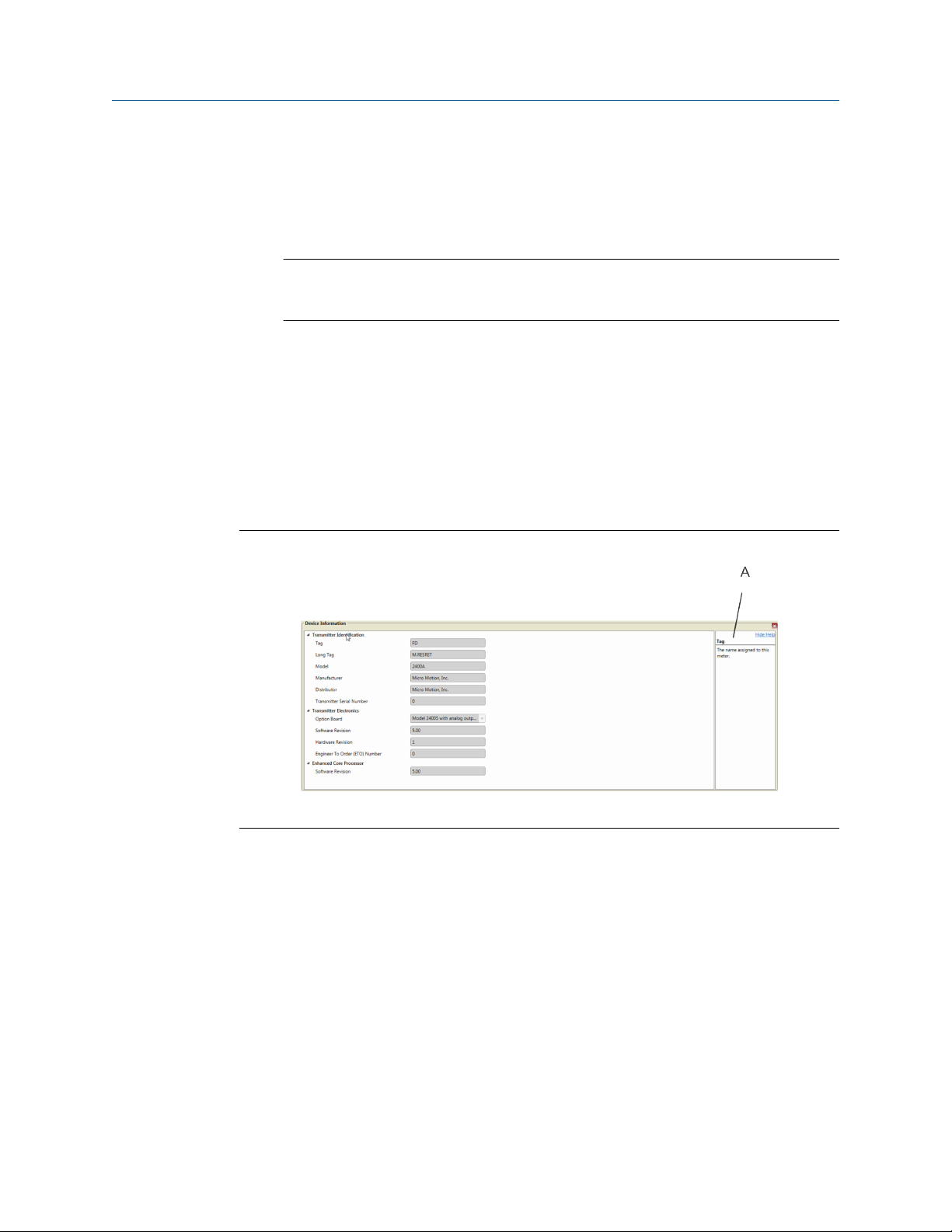
2.6 Show Help for software interface options
In ProLink III, you can choose to show or hide field or parameter descriptions for a
displayed interface. Depending on the field or parameter selected, a description appears in
the Help screen to explain more about the selected option. The default setting is to hide,
or not show, the Help screen.
Figure 2-4: Using the Help feature
A. Display the Help screen to view descriptive information about a selected parameter.
Procedure
1. To show helpful information about a field in the active interface:
a) Select Show Help.
Show Help is the blue icon with the question mark.
A Help screen displays to the right of the interface options.
b) To view a description of a specific control, place the cursor over an active
field or parameter.
A description of the field/feature appears in the Help screen.
2. To hide or close the Help screen, click Hide Help.
User Manual 17
Page 18

Working with ProLink III User Manual
February 2020 MMI-20020246
2.7 Use ProcessViz
Procedure
1. Using ProLink III, create a data log and save it.
See Create data logs
2. Use any of the following methods to open ProcessViz.
From the ProLink III startup screen, select Open ProcessViz.
From Device Tools → Trending → Create Trend Chart…, select Open ProcessViz.
From Device Tools → Data Logging, select Open in ProcessViz when logging stops
3. Drag your saved data log file into ProcessViz.
18 Micro Motion ProLink III
Page 19

User Manual Connect to one or more devices
MMI-20020246 February 2020
3 Connect to one or more devices
3.1 Connect to a device
In ProLink III, you can connect to one or more devices, depending on your system
configuration.
Prerequisites
Before you can connect to a device, ensure that you have:
• Met all the requirements for the software installation
• An active temporary or permanent license
• Made the necessary wire connections from your computer to the device and/or
network. See Device wiring terminals for ProLink III connections or the configuration
and use manual for more information on wiring to your device.
Procedure
1. Start ProLink III.
2. On the ProLink III start-up screen, select Connect to Physical Device.
3. Set Protocol to the protocol to be used for the connection.
For HART®/Bell 202 to USB port connections using the supplied converter, enable
Toggles RTS.
4. Set Serial Port to the PC COM port you are using to connect to the device.
If you are using a USB converter or a USB A-type to A-type cable and need to locate
the COM port for the connection, refer to the Windows Device Manager to obtain
that information.
5. Specify additional communication parameters.
• If you are making a service port connection, default values are used for all
remaining communications parameters. No configuration is required.
• If you are making a HART/Bell 202 connection, set Address to the HART address
of the device. Default values are used for all remaining communications
parameters. No additional configuration is required.
• If you are connecting to an MVD Direct Connect system, set the remaining
communication parameters to any of the supported values. The core processor
auto-detects incoming communications settings and switches to match.
Table 3-1: Auto-detection limits for MVD Direct Connect
Parameter Option
Protocol Modbus RTU (8-bit)
Modbus ASCII (7-bit)
Baud rate Standard rates from 1200 to 38,400
User Manual 19
Page 20

Connect to one or more devices User Manual
February 2020 MMI-20020246
Table 3-1: Auto-detection limits for MVD Direct Connect (continued)
Parameter Option
Parity Even, odd, none
Stop bits 1, 2
• If you are making an RS-485 connection to any 2400S transmitter, set Address
to the Modbus address of the device. For all remaining communications
parameters, the device auto-detects the incoming values and switches to
match.
Table 3-2: Auto-detection limits for 2400S transmitters
Parameter Option
Protocol Modbus RTU (8-bit)
Modbus ASCII (7-bit)
Address Responds to both:
— Service port address (111)
— Configured Modbus address (default =
1)
Baud rate Standard rates from 1200 to 38,400
Stop bits 0, 1
Parity Even, odd, none
• If you are making an RS-485 connection to a CDM, GDM, SGM, FDM, FVM, or
HFVM meter, set Address to the Modbus address of the device. For all remaining
communications parameters, the device auto-detects the incoming values and
switches to match.
Table 3-3: Auto-detection limits for Density Viscosity meters
Parameter Option
Protocol Modbus RTU (8-bit)
Modbus ASCII (7-bit)
Address Responds to both:
— Service port address (111)
— Configured Modbus address (default =
1)
Baud rate Standard rates from 1200 to 38,400
Stop bits 0, 1
Parity Even, odd, none
6. To connect to a device, you have the following options:
• Select Address, and enter the address configured for the device.
• Select Tag, and enter the tag configured for the device.
20 Micro Motion ProLink III
Page 21

User Manual Connect to one or more devices
MMI-20020246 February 2020
• To view a list of available devices, select Connect Via Polling and click Poll.
Select your device from the list.
7. Select Connect.
• If you are connecting to a 1500, 2500, 3000, or LFT DIN rail mount transmitter,
using either a service port connection or an RS-485 connection, the RS-485
terminals are available in service port mode for 10 seconds after transmitter
power-up.
— If a service port connection is made during this interval, the terminals will
remain in service port mode until the next power cycle, and you can make a
service port connection at any time.
— If no connection is made during this interval, the terminals switch to RS-485
mode and you can make an RS-485 connection at any time.
— If the terminals are in one mode and you want to use the other mode, you
must power-cycle the transmitter to reset the mode, then make the
appropriate connection at the appropriate time.
• If you are connecting to any other device, or using any other connection type,
you can make the connection at any time.
8. If ProLink III fails to connect, troubleshoot the device connection.
Related information
Default communication values
Troubleshoot a device connection
3.2 Default communication values
Coriolis transmitters
Device
1500/2500 Bell 202
1500/2500 LFT
DIN rail
1700/2700 Bell 202
1700/2700 LFT
field-mount
2200S Bell 202
2400S with
analog outputs
3000 Bell 202
Physical layer
RS-485
RS-485
RS-485
Bell 202
RS-485
RS-485
(1)
(2)
(1)
(2) (3)
(4)
(5)
(1)
(5)
(1)
(2)
Protocol Baud Stop bits Parity Address
HART 1200 1 Odd 0
Modbus RTU 9600 1 Odd 1
HART 1200 1 Odd 0
HART 1200 1 Odd 0
HART 1200 1 Odd 0
HART 1200 1 Odd 0
Modbus (RTU
or ASCII)
HART 1200 1 Odd 0
Modbus RTU 9600 1 Odd 1
Auto-detect Auto-detect Auto-detect 1
Default values
User Manual 21
Page 22

Connect to one or more devices User Manual
February 2020 MMI-20020246
Device Physical layer
Default values
Protocol Baud Stop bits Parity Address
(6)
(1)
HART 1200 1 Odd 0
Modbus (RTU
Auto-detect Auto-detect Auto-detect 1
9739 MVD Bell 202
RS-485
or ASCII)
(7)
(1)
(1)
HART 1200 1 Odd 0
HART 1200 1 Odd 0
Modbus (RTU
Auto-detect Auto-detect Auto-detect 1
4200 Bell 202
5700 Bell 202
RS-485
or ASCII)
(1) Connection to primary mA Output, or to HART clips, if available.
(2) Connection to RS-485 terminals.
(3) Available only on 1700/2700 transmitters with analog outputs or LF transmitters with output option codes 1 or 3.
(4) Connection to HART clips
(5) Connection to service port.
(6) Connection to RS-485 terminals or service port.
(7) Connection to RS-485 terminals
Density and viscosity meters
Device Physical layer
CDM, GDM,
SGM, FDM,
FVM, or HFVM
Bell 202 HART 1200 1 Odd 0
RS-485 Modbus (RTU
Protocol Baud Stop bits Parity Address
Auto-detect Auto-detect Auto-detect 1
or ASCII)
Default values
RFT97xx and IFT97xx transmitters
If your transmitter is not using default values, refer to site documentation for the values you are using.
Device Physical layer
Protocol Baud Stop bits Parity Address
IFT9701/
IFT9703
(1)
Bell 202
RFT9712 Bell 202
RS-485
RFT9739v2 Bell 202
RS-485
RFT9739v3 Bell 202
RS-485
(2)
(2)
(3)
(2)
(3)
(2)
(3) (4)
HART 1200 1 Odd 0
HART 1200 1 Odd 0
HART 1200 1 Odd 0
HART 1200 1 Odd 0
HART 1200 1 Odd 0
HART 1200 1 Odd 0
Std. comm Modbus RTU 9600 1 Odd 1
User defined HART 1200 1 Odd 0
(1) IFT9701/9703 communication parameter are not configurable. The settings shown here are always in effect.
(2) Connection to primary mA output, or to HART clips, if available.
Default values
22 Micro Motion ProLink III
Page 23

A
User Manual Connect to one or more devices
MMI-20020246 February 2020
(3) Connection to RS-485 terminals.
(4) Dip switch settings on the transmitter are used to select either Std. comm or User defined.
Rosemount magnetic and vortex flow meters
Device Physical layer
8782 Bell 202
8732EM Bell 202
RS-485 Modbus RTU 9600 1 Even 1
8732ES Bell 202
8712EM Bell 202
RS-485 Modbus RTU 9600 1 Even 1
8800D Bell 202
(1) HART communication parameters are not configurable. The settings shown here are always in effect.
(1)
(1)
(1)
(1)
(1)
Protocol Baud Stop bits Parity Address
HART 1200 1 Odd 0
HART 1200 1 Odd 0
HART 1200 1 Odd 0
HART 1200 1 Odd 0
HART 1200 1 Odd 0
Default values
3.3 Make an additional device connection
If you are working in a multidrop network or have two or more serial or USB port
connections, you can simultaneously connect to multiple devices in your process. This
feature allows you to more easily view your system performance and troubleshoot process
conditions across more than one device.
Additionally, when you have multiple devices connected, you can view the performance of
each device using the multi-device comparison tool.
Figure 3-1: Add an additional connection
A. From the main screen, you can easily connect to another device or open a simulated or
offline configuration.
User Manual 23
Page 24

Connect to one or more devices User Manual
February 2020 MMI-20020246
Procedure
1. Select Physical under Connect To.
2. Select Go.
3. Use the Protocol parameter to specify your connection type.
If you are making a HART/Bell 202 to USB port connection and using the supplied
converter, enable Toggles RTS.
4. Set Serial Port to the PC COM port you are using to connect to the device.
5. Specify additional communication parameters, as needed.
6. To select the device to connect to, you have the following options:
• Select Address to enter the unit address.
• Select Tag to enter the tag description.
• To view a list of available devices, select Connect Via Polling and select Poll.
7. Select the device that you want to connect to, and click Connect.
ProLink III attempts to make the connection. If the connection is successful, the
connected device displays in the ProLink III main screen. If the connection fails, see
Troubleshoot a device connection for more information.
3.4 Use the guided connection wizard
To assist you in making a connection to a device, you can use the guided connection
wizard. This feature provides a drag-and-drop interface, device information, and terminal
information to help you set up the connection.
Procedure
1. Select Physical under Connect To
2. Select Go.
3. Select Connect via Guided Connection Wizard.
4. Follow the on-screen instructions.
5. Select Connect.
3.5 Device wiring terminals for ProLink III connections
When wiring your computer to a device, use the following tables for the terminals that are
specific to your device and connection type.
24 Micro Motion ProLink III
Page 25

User Manual Connect to one or more devices
MMI-20020246 February 2020
Coriolis meters
Terminals for connection types
Device
HART/Bell 202 HART/RS-485 Modbus/RS-485 Service port
PV+ PV– A B A B A B
4200 1 2
5700 1 2 9 10 9 10 USB-A type
9739 MVD 17 18 26 27 26 27 Service port clips
HART clips
1700/2700 with
1 2 5 6 5 6 8 7
analog outputs
LFT field-mount with
1 2 5 6 5 6 8 7
output option codes
1, 3
1700/2700 with
intrinsically safe
outputs
(1)
2700 with
1 2 8 7
1 2 8 7
configurable input/
outputs
LFT field-mount with
1 2 8 7
output option code 4
2700 with
8 7
FOUNDATION™ fieldbus
LFT field-mount with
8 7
output option code 6
2700 with PROFIBUS-
8 7
PA
2200S HART clips
2400S with analog
outputs
2400S with
DeviceNet
®
2400S with PROFIBUS-
1 2 Service port clips
HART clips
Service port clips
Service port clips
DP
3000 panel-mount
c2 a2 c32 a32 c32 a32 c32 a32
with solder-tail or
screw-type
connectors
3000 panel-mount
14 15 24 25 24 25 24 25
with I/O cables
3000 rack-mount c2 a2 c32 a32 c32 a32 c32 a32
3000 field-mount 2 1 11 12 11 12 11 12
User Manual 25
Page 26

Connect to one or more devices User Manual
February 2020 MMI-20020246
Terminals for connection types
Device
HART/Bell 202 HART/RS-485 Modbus/RS-485 Service port
PV+ PV– A B A B A B
1500/2500 21 22 33 34 33 34
LFT DIN rail with
21 22 33 34 33 34
output option codes
2, 5, 8
™
MVD
Direct Connect™ with
no barrier
(2)
MVD Direct Connect
3 4
13 14
with MVD Direct
Connect I.S. barrier
• Connection to
• Connection to
barrier
(3)
3 4
core processor
• Core processor
(4)
3 4
(1) If connecting to terminals 1 and 2, terminals must be externally powered, with a minimum of 250 W and 17.5 volts.
Requirement does not apply to service port.
(2) Connection is not intrinsically safe.
(3) Intrinsically safe connection
(4) Connecting directly to the core processor terminals is supported for sensor-mounted core processors (4-wire remote
installations) or stand-alone core processors (remote core processor with remote transmitter installation).
Density and viscosity meters
Terminals for connection types
Device
HART/Bell 202 HART/RS-485 Modbus/RS-485 Service port
PV+ PV– A B A B A B
CDM, GDM, SGM,
FDM, FVM, HFVM
+ terminal
in
leftmost
terminal
pair
– terminal
in
leftmost
terminal
pair
A B A B
RFT97xx and IFT97xx transmitters
Terminals for connection types
Device
IFT9701/9703 4-20 4-20
RFT9712 17 16 21 22
RFT9739 rack-mount Z30 D30 Z22 D22 Z22 D22
HART/Bell 202 HART/RS-485 Modbus/RS-485 Service port
PV+ PV– A B A B A B
26 Micro Motion ProLink III
Page 27

User Manual Connect to one or more devices
MMI-20020246 February 2020
Terminals for connection types
Device
HART/Bell 202 HART/RS-485 Modbus/RS-485 Service port
PV+ PV– A B A B A B
RFT9739 field-mount 17 18 27 26 27 26
Rosemount magnetic and vortex flow meters
Terminals for connection types
Device
8782 with internallypowered output
8782 with IS or
externally-powered
output
8732EM with
internally-powered
output
8732EM with IS or
externally- powered
output
8712E and 8712H 7 8
HART/Bell 202 HART/RS-485 Modbus/RS-485 Service port
PV+ PV– A B A B A B
8 7
7 8
1 2
2 1 2 1
8712EM with
8 7
internally-powered
output
8712EM with IS or
7 8 7 8
externally-powered
output
8600 and 8800D + terminal
in 4-20
mA pair
- terminal
in 4-20
mA pair
Added resistance for ProLink III connections
If you are making a HART connection, refer to this table for any additional resistance
required for your device. For additional wiring information, see the appropriate
configuration and use manual.
Device
HART/Bell 202 HART/RS-485 Modbus/RS-485 Service port
IFT9701/9703 250–600 Ω
RFT9712 250–1000 Ω See Footnote
RFT9739 Rack-mount 250–1000 Ω See Footnote
RFT9739 field-mount 250–1000 Ω See Footnote
Resistance range for connection type
(1)
(1)
(1)
See Footnote
See Footnote
(1)
(1)
User Manual 27
Page 28

Connect to one or more devices User Manual
February 2020 MMI-20020246
Device Resistance range for connection type
HART/Bell 202 HART/RS-485 Modbus/RS-485 Service port
4200 250–600 Ω
5700 250–600 Ω See Footnote
9739 MVD 250–600 Ω See Footnote
1700/2700 with analog outputs 250–600 Ω See Footnote
LFT field-mount with output option
250–600 Ω See Footnote
(1)
(1)
(1)
(1)
See Footnote
See Footnote
See Footnote
See Footnote
codes 1, 3
1700/2700 with intrinsically safe
250–600 Ω See Footnote
outputs
2700 with configurable input/ outputs 250–600 Ω See Footnote
LFT field-mount with output option
250–600 Ω See Footnote
code 4
2700 with FOUNDATION fieldbus See Footnote
LFT field-mount with output option
code 6
(1)
(1)
(1)
(1)
See Footnote
See Footnote
See Footnote
See Footnote
(1)
(1)
(1)
(1)
(1)
(1)
(1)
(1)
2700 with PROFIBUS-PA
2200S 250–600 Ω
2400S with analog outputs 250–600 Ω See Footnote
2400S with DeviceNet See Footnote
2400S with PROFIBUS-DP See Footnote
Series 3000 250–600 Ω See Footnote
(1)
See Footnote
1500/2500 250–600 Ω See Footnote
CDM, GDM, SGM, FDM, FVM, HFVM 250–600 Ω See Footnote
LFT DIN rail with output option codes
See Footnote
(1)
(1)
(1)
(1)
See Footnote
2, 5, 8
MVD Direct Connect See Footnote
8732E with internally-powered output 250-500 Ω See Footnote
8732E with IS or externally-powered
250-600 Ω See Footnote
(1)
(1)
(1)
output
8712E and 8712H 250-600 Ω
8600 and 8800D 250-1250 Ω
(1) RS-485 connections may require added resistance if the connection is long-distance or if there is external noise that
interferes with the signal. Add two 120-Ω resistors in parallel with the output, one at each end of the communication
segment.
(1)
(1)
(1)
(1)
28 Micro Motion ProLink III
Page 29

User Manual Connect to one or more devices
MMI-20020246 February 2020
3.6 Troubleshoot a device connection
If you cannot connect to a device, review the following information and follow the
suggestions. If you cannot resolve the problem, contact customer support at
www.emerson.com.
Procedure
1. Check all wiring between your computer and the device.
2. Ensure all components are powered up. Refer to the configuration and use manual
for more information.
3. Check all connection parameters and ensure they are correct for both ProLink III and
the device.
4. Ensure you have the correct USB drivers installed for the device.
5. Ensure that ProLink III is configured for the correct COM port.
6. Make sure that you do not have interference over the COM port.
7. If you use the configured COM port for any other program, verify that the other
program is not currently running.
8. For HART connections to 1700/2700 and 8732E transmitters with the intrinsically
safe outputs option board, ensure that the terminals are externally powered.
9. Try adding resistance to the connection.
• For HART connections, verify that there is a 250–600 Ω resistor in parallel in the
communications circuit.
• For HART connections to 1700/2700 and 8732E transmitters with the
intrinsically-safe outputs option board, ensure that the resistor is in series.
Attach the modem across the resistor.
• RS-485 connections may require added resistance if the connection is long-
distance or if there is external noise that interferes with the signal. Add two 120Ω resistors in parallel with the output, one at each end of the communication
segment.
10. For RS-485 connections, swap the leads between the two terminals and try again.
11. For Modbus network connections, ensure that ProLink III is the only Modbus master
active on the network.
12. For RS-485 connections, try connecting through the service port, if available on
your device.
13. For HART/Bell 202 connections:
a) If burst mode is enabled, try disabling it.
b) Ensure that polling for external pressure/temperature is disabled.
c) Ensure that ProLink III is the only master on the network.
14. For HART connections using the USB HART Interface:
a) Ensure that you have selected Toggles RTS in the ProLink III connection
screen.
User Manual 29
Page 30

Connect to one or more devices User Manual
February 2020 MMI-20020246
b) Ensure that the required Windows driver is installed on your PC. If this driver
is not installed, Windows will not recognize the USB converter when it is
plugged into the USB port.
15. For connections to the 2400S transmitter, if you are using Modbus ASCII protocol
with an RS-485 connection rather than a service port connection, ensure that
Modbus ASCII support is enabled on your transmitter.
3.7 Work with one device when several are connected
When you connect to multiple devices simultaneously, a device tab is displayed for each
transmitter connection in the ProLink III main screen. Each device tab displays an image of
the transmitter, the transmitter name, the transmitter address, and the transmitter status.
Note
If you disconnect from one device when multiple devices are connected, the device tab is
no longer available for the disconnected device.
Figure 3-2: View of the active device in ProLink III
A. The highlighted tab is the active device in ProLink III. An active device is the device for
which process- and device-specific information is displayed in the main screen.
Procedure
Click on the appropriate device tab to view or configure a specific transmitter.
This device becomes the active device, and ProLink III updates the main screen to show the
process information for the selected device.
3.8 View the device status and alerts
In ProLink III, the status of the device is displayed in the upper-left corner of the device tab
for each active transmitter. When alerts are present, a status icon displays depending on
the type of alert and whether or not it is active. When alerts are present, the alert code and
description display under Alerts.
30 Micro Motion ProLink III
Page 31

User Manual Connect to one or more devices
MMI-20020246 February 2020
Procedure
1. To view the transmitter status, refer to the transmitter device tab.
Option Description
A red failure icon displays when a meter failure has occurred and must be
addressed immediately. The alert is displayed under Failed: Fix Now.
A yellow maintenance icon displays when a condition has occurred that
can be fixed at a later time. This icon displays only if no failure condition
exists. The alert is displayed under Maintenance: Fix Soon.
A blue advisory icon displays when a condition has occurred, but requires
no maintenance. This icon displays only if no failure or maintenance
condition exists. The alert is displayed under Advisory: Informational.
2. If an alert exists under Alerts:
• Select the alert name to view more information about troubleshooting the issue.
• Select Detail View to display the troubleshooting information directly below the
listed alert.
3.9 Disconnect from a device
Procedure
To disconnect from a connected device, simulated configuration, or an offline
configuration, click Device Tools → Disconnect.
User Manual 31
Page 32

Connect to one or more devices User Manual
February 2020 MMI-20020246
32 Micro Motion ProLink III
Page 33

User Manual Use configuration data
MMI-20020246 February 2020
4 Use configuration data
4.1 Configuration data transfer between devices
ProLink III provides the capability to save and load configurations. The configuration
transfer capabilities support easy backup and restoration of device configurations, and
easy replication of configuration sets across compatible devices.
Restriction
Devices must have the same measurement technology. For example, you cannot transfer
data between a Coriolis meter and a Magmeter.
As a best practice, download all configurations to a computer as soon as your
configuration is complete.
You can also import configuration data that was saved in a previous version of ProLink III.
Related information
Import data from a previous version of ProLink
4.2 Save a device configuration
Procedure
1. Connect to the device that you want to download the configuration data from.
2. Select Device Tools → Configuration Transfer → Save or Load Configuration
Data.
Example
3. Select the configuration data you want to save under Configuration.
By default, all configuration data is selected to save to the configuration file.
4. Select Save, then specify a file name and location on your computer.
5. Select Start Save.
User Manual 33
Page 34

Use configuration data User Manual
February 2020 MMI-20020246
4.3 Restore or load a configuration file
Tip
To restore or load a configuration file saved in a previous version of ProLink, use the data
import feature for your version of ProLink (see Import data from a previous version of
ProLink).
Procedure
1. Connect to the device that you want to restore or load configuration data to.
2. Select Device Tools → Configuration Transfer → Save or Load Configuration
Data.
3. Select the configuration data you want to load to the active device under
Configuration.
By default, all configuration data is selected.
4. Select Load, then select the file to load to your device.
5. Select Start Load.
4.4 Import data from a previous version of ProLink
In ProLink III, you can restore or load a transmitter configuration file saved in a previous
version of ProLink. Once you import the data, you can then save the transmitter
configuration to a ProLink III file format.
Important
Micro Motion recommends that you import the data from a previous version of ProLink
into a simulated configuration versus a connected device. You can save the data in the
simulated configuration as you would for an active device, without the possibility of
affecting the current process.
Procedure
1. To import configuration data saved in a previous version of ProLink:
• For ProLink I: select Device Tools → Configuration Transfer → Import Data
from ProLink I.
• For ProLink II: select Device Tools → Configuration Transfer → Import Data
from ProLink II.
2. Click Browse to navigate to the file location on your computer.
3. Click Import.
4. To save the configuration data, click Device Tools → Configuration Transfer →
Save or Load Configuration Data.
See Import data from a previous version of ProLink for more information.
34 Micro Motion ProLink III
Page 35

User Manual Use configuration data
MMI-20020246 February 2020
4.5 Configure a device offline
In ProLink III, you can efficiently manage the configuration of a device before uploading
the information.
• Create a new configuration file or open and edit an existing configuration file.
• Upload a previously-saved configuration file as a template.
Figure 4-1: Create or edit a configuration offline
Procedure
1. To use offline configuration, do one of the following:
• From the start-up screen in ProLink III, click Use Offline Configuration.
• From the main screen in ProLink III, select Offline under Connect To, and click
Go.
2. Do one of the following:
• To create a new configuration file for a specific device, select New Offline
Configuration File.
a. Enter a file name in Name.
b. Select the device type in Select Device.
c. Select the version for the device.
The default setting is the latest version available for the selected device.
d. Optional: Select any additional features available for the configuration of
the selected device in Device Features.
e. Optional: Select Load Downloaded Configuration File and browse to the
file location to upload a saved configuration file to build from for the new
device configuration.
User Manual 35
Page 36

Use configuration data User Manual
February 2020 MMI-20020246
f. Click Connect.
An offline device screen opens to allow you to verify and edit the device
configuration data.
• To open and edit an existing configuration file, select Open Existing
Configuration File.
a. Select the configuration file from the displayed list of previously created
configuration files.
b. Select Open.
3. With the offline configuration file open, select Device Tools → Configuration to
configure the device.
4. To save the configuration data to transfer to another device, select Device Tools →
Configuration Transfer → Save or Load Configuration Data. See Save a device
configuration for more information.
5. To close the offline session, select Device Tools → Disconnect.
4.6 Print a configuration report
You can print a configuration report that shows the current calibration and configuration
parameters set for the active device.
Procedure
Select Device Tools → Print.
4.7 Restore the factory configuration
You can restore the configuration settings for the active device to the default
configuration data set for the device when it shipped from the factory.
Restriction
See the appropriate transmitter configuration and use manual to understand whether or
not this option is available for your device.
Procedure
Select Device Tools → Configuration Transfer → Restore Factory Configuration.
36 Micro Motion ProLink III
Page 37

A
User Manual Use the process variables view
MMI-20020246 February 2020
5 Use the process variables view
5.1 Set up the process variables view
When you connect to a device, the process variables display on the main screen of
ProLink III. The default display view for process variables is the Analog Gauge view. You can
choose which variables display at the gauge-level view, as well as which are displayed in
the gauges. Additionally, you can customize the gauge settings, or change the display
format to show only digital values.
Figure 5-1: Process variables view
A. The Process Variables view shows the current performance of selected variables for the
connected device.
5.1.1
Change the process variables displayed
You can change the process variables displayed in the Process Variables view.
Tip
If you have customized the analog gauge view for a specific process variable, when you
change the variable displayed for that gauge the analog gauge view is reset to the default
settings.
Procedure
1. To change the variable shown in the top-level gauge or digital view:
a) Select the drop-down arrow next to the variable name (such as Mass Flow
Rate).
b) Select a variable to display.
2. To change the variable shown in the mid- or bottom-level digital view:
User Manual 37
Page 38

A
Use the process variables view User Manual
February 2020 MMI-20020246
a) Select the drop-down arrow next to the variable name (such as Mass Total).
b) Select a variable to display.
5.1.2 Change the display format
You can change the process variable display format to be Analog Gauge or Digital. The
default process variables display is Analog Gauge.
Procedure
1. Select Process Variables → Display Format.
2. Choose the display format.
Option Description
Analog Gauge Displays three process variable measurements as an analog gauge,
with the digital measurements shown directly below the gauge.
Analog Gauge is the default display format.
Digital Displays the process variable measurements in digital format only.
5.1.3 Customize the analog gauge view
If you choose the Analog Gauge view for the process variables display, you can customize
each gauge to display specific measurement ranges or change the number of tick marks
shown on the gauge.
Figure 5-2: Customize the gauge view
A. Change the gauge view and settings using the Gauge Customization feature.
Important
When you customize the gauge view, the settings only apply to the current process
38 Micro Motion ProLink III
variable displayed. If you change the variable displayed for that gauge, the analog gauge
view is reset to the default settings.
Page 39

User Manual Use the process variables view
MMI-20020246 February 2020
Procedure
1. Right-click the desired gauge, and select Gauge Customization.
2. In the Gauge Customization dialog box:
a) Under Range, select the range for the gauge.
• Use Output Range sets the gauge view to display the configured output
limits.
• Use Sensor Limits sets the gauge view to display the configured sensor
limits.
• Use Custom Range allows you to enter a specific low/high range limit for
the gauge view in Low Value and High Value.
b) Under Tick Marks, select the number of major and minor tick marks to
display on the gauge.
Tip
• See Preview to view how the gauge displays the selected settings before saving
the settings to the main screen.
• To reset your gauge view to the default settings shown at startup, click Reset.
5.2 Reset totals
Reset displays next to the process variable view for totalizers or inventories to allow you to
reset the value to zero. When these controls are not displayed, the Reset option is not
available.
Tip
Inventories can be reset from ProLink III only if this function is enabled in ProLink III.
Procedure
Select Reset to reset the selected value to zero.
User Manual 39
Page 40

Use the process variables view User Manual
February 2020 MMI-20020246
40 Micro Motion ProLink III
Page 41

User Manual Monitor the process, device, or device health
MMI-20020246 February 2020
6 Monitor the process, device, or
device health
6.1 Monitor process trends
Viewing your process trends in ProLink III allows you to monitor selected process,
diagnostic, and output variables for one or more connected devices. Monitoring the
device performance this way provides a snapshot of what is happening with your process
and can help you determine techniques for improving the productivity and quality of your
system.
The trending feature instantaneously charts the variables you select in a graphical format.
You can view the process performance live in ProLink III or ProcessViz, as well as save or
print the information for later use.
6.1.1
Create a trend chart
Procedure
1. Select Trend at the bottom of the main screen, or select Device Tools → Trending
→ Create Trend Chart.
Example
A trend chart allows you to graphically map your process performance. For view
data, select the device, the variables, and define the desired interval.
2. Under Process Variables and Diagnostic Variables, select the variables that you
want shown on the graph.
Restriction
You can show a maximum of four variables in a chart at one time.
User Manual 41
Page 42

A
Monitor the process, device, or device health User Manual
February 2020 MMI-20020246
As you select the variables, the current measurements are immediately shown and
plotted in the graphical view.
3. To clear the current data displayed in the graphs, click Clear.
Once the data is cleared, current measurements immediately begin to plot for the
same selected variables.
4. Optional: Change the trending interval for which the data points are displayed
under Trending Interval. You can choose between seconds or minutes, and define
the amount.
6.1.2 Read a trend chart
As you select variables to display on the trend chart, the current measurements are
immediately shown and begin to plot according to the chart settings.
Procedure
1. See Figure 6-1 to understand how to read a trend chart.
Figure 6-1: Reading a trending chart
A. The key at the top of the graph shows the variables displayed in the graphs, and the corresponding color
chosen to represent each variable in the graph.
• The Y axis displays the measurement range for the specific variable identified.
• The X axis displays the time of each data point shown, according to the trending
interval set.
2. Optional: To maximize the graphical view to the size of your computer screen,
select Maximize Graph.
42 Micro Motion ProLink III
Page 43

User Manual Monitor the process, device, or device health
MMI-20020246 February 2020
6.1.3 Compare trends
When you have more than one device connected, you can compare the measurements
and performance of up to two devices. This feature displays the performance data for each
device and the difference between the two measurements in one graph for easy viewing.
• When you have multiple devices connected, you can compare the measurements and
performance of up to two devices in one graph.
• When you select the devices and variables to compare, the data is automatically
plotted to a graph. A graph is created for each variable chosen, and you use the scroll
bar to view the different graphs.
Procedure
1. Select Device Tools → Trending → Compare Trends.
2. Select the devices to compare.
3. Under Process Variables and Diagnostic Variables, select the variables that you
want to show data for.
Restriction
You can show up to a maximum of four variables.
6.1.4
As you select the variables, the current measurements are immediately shown and
plotted in a graph. A graph is created for each variable, showing the measurement
for each device and the difference between the two measurements. You must use
the scroll bar to view multiple graphs displayed in the trending screen.
4. Optional: Change the trending interval for which the data points are displayed
under Trending Interval. You can choose between seconds or minutes, and define
the amount.
5. Optional: To clear the current data displayed in all graphs, select Clear Graph.
Once the data is cleared, current measurements immediately begin to plot for the
same selected variables.
6. Optional: To remove a graph and deselect the variable, select Remove Graph.
Save or print a trend chart
While viewing a trend chart, you can choose to export the current data to a file for later
use, or you can choose to print the current data.
Procedure
• To save the current data to a file on your computer, select Export Graph.
• To print the current data, select Print.
6.2 Create data logs
The data logging feature allows periodic logging of user-selected device data, including
process variables, diagnostic variables, and output levels. Data logged can be viewed or
imported into external programs such as spreadsheets for further analysis. To create a
User Manual 43
Page 44

Monitor the process, device, or device health User Manual
February 2020 MMI-20020246
data log, you need to define the log file, specify the type of data to be logged and the
frequency of data points, and start the logging process.
Figure 6-2: Data logging feature
6.2.1
Procedure
To access the data logger, click Data Logging at the bottom of the main screen, or select
Device Tools → Data Logging.
Define a log file
Procedure
1. To specify the log file name and location, under Log Settings:
a) In File Path, click ... to navigate to the location on your computer where the
log should be saved.
b) Navigate to the desired location on your computer and enter the file name in
File name.
The file is saved as a .csv (comma-separated values) file, for import into
standard spreadsheets.
2. To set the frequency of data points in the log, specify the update rate and unit in
Logging Interval.
Tip
If you are using HART protocol, be careful not to set the logging frequency too high.
On HART/Bell 202, log as few variables as possible with a logging interval 5-10
seconds (5000–10000 milliseconds). The same restrictions apply to HART/RS-485
at lower baud rates, especially 1200 baud.
44 Micro Motion ProLink III
Page 45

User Manual Monitor the process, device, or device health
MMI-20020246 February 2020
3. Optional: Select the Include Status Error Logging check box to cause ProLink III to
write status errors to the log.
6.2.2 Specify the log contents
Procedure
1. Select Data Logging… at the bottom of the screen.
Variables that are available for inclusion in the log file are shown in the Log These
Variables panel with default variables already selected. The default selections are
needed for troubleshooting.
2. Select the check boxes next to the variables you would like to include in the log, and
deselect the variables to exclude.
To select an entire group of variables, you can select the group heading check box
such as Process Variables, Output Variables, Diagnostics.
3. Optional: To add a note to the log while the data logger is running, enter the note in
Data Point Note and click Add Note.
The note is added to the current end of the log. Subsequent data points will be
added after the note.
6.2.3
6.2.4
Save or load log settings
Saving and loading the data logging settings allows you to reuse previous log session
settings.
Procedure
• To save the current log settings to a file on your computer, select Save Settings.
• To load previously saved log settings to the current log session, select Load Settings.
Start and stop the logging function
You can start and stop the data logger either manually or automatically. Additionally, you
can combine the methods to control the data logger. For example, you can start the
logger manually, but then set a time to stop it automatically.
Procedure
• To manually control the data logger:
• To start the data logger manually, select Start.
• To stop the data logger manually, select Stop.
• To automate control of the data logger you can use the features under Timer.
• To start the data logger at a specific time:
1. Select the down arrow to select a specific date in From. Once you select the
date, you can use the up and down arrows inside the date field to change the
time.
2. Select Enable to set the data logger to start at the specified time.
User Manual 45
Page 46

Monitor the process, device, or device health User Manual
February 2020 MMI-20020246
• To stop the data logger at a specific time:
1. Select the down arrow to select a specific date in To. Once you select the
date, you can use the up and down arrows inside the date field to change the
time.
2. Select Enable to set the data logger to stop at the specified time.
6.3 Compare multiple devices
When you are connected to more than one device, you can use the multi-device
comparison tool to view the performance or configuration data of each connected device
from one main screen. For example, this tool can allow you to easily verify the
performance of a test meter against a known performance meter under the same process
conditions.
With this tool, you are not limited by the number of variables you can select to show at
one time.
The multi-device comparison tool allows you to view performance and configuration data
for multiple devices in a table format. You can choose to:
• Show data for all connected devices
• Select data for all connected devices
• Select to show only two devices
Figure 6-3: Multi-device comparison tool
46 Micro Motion ProLink III
Page 47

User Manual Monitor the process, device, or device health
MMI-20020246 February 2020
Procedure
Select Multi-Device Comparison (located in the lower left corner of the ProLink III main
screen).
6.3.1 Select devices to compare
You can select the specific devices you want to compare data for, when you have more
than two devices connected. The default setting is to show all available devices when you
open the multi-device comparison tool, but you have the option to change this setting.
Procedure
1. Select Add Device.
2. Enable the check boxes for only the devices you want to view.
The screen automatically refreshes to show only the selected devices.
6.3.2
6.3.3
Compare processes for multiple devices
Procedure
1. In the multi-device comparison screen, select the down arrow next to the
performance variable category you want to show data for.
Note
With this tool, you are not limited in the number of variables you can select to show
and compare data for.
2. Select Close.
Compare configuration data for multiple devices
Procedure
1. In the multi-device comparison screen, click the down arrow next to Configuration.
Note
With this tool, you are not limited in the number of variables you can select to show
and compare data for.
2. Select Close.
User Manual 47
Page 48

*MMI-20020246*
MMI-20020246
Rev. AG
2020
Micro Motion Inc. USA
Worldwide Headquarters
7070 Winchester Circle
Boulder, Colorado USA 80301
T +1 303-527-5200
T +1 800-522-6277
F +1 303-530-8459
www.emerson.com
Micro Motion Asia
Emerson Automation Solutions
1 Pandan Crescent
Singapore 128461
Republic of Singapore
T +65 6363-7766
F +65 6770-8003
©
20
20 Micro Motion, Inc. All rights reserved.
The Emerson logo is a trademark and service mark of Emerson Electric Co. Micro Motion, ELITE,
ProLink, MVD and MVD Direct Connect marks are marks of one of the Emerson Automation
Solutions family of companies. All other marks are property of their respective owners.
Micro Motion Europe
Emerson Automation Solutions
Neonstraat 1
6718 WX Ede
The Netherlands
T +31 (0) 318 495 555
T +31 (0) 70 413 6666
F +31 (0) 318 495 556
www.emerson.com/nl-nl
Micro Motion United Kingdom
Emerson Automation Solutions
Emerson Process Management Limited
Horsfield Way
Bredbury Industrial Estate
Stockport SK6 2SU U.K.
T +44 0870 240 1978
F +44 0800 966 181
 Loading...