

Page 1
Power Conditioner
MCR Hardwired Series – 50 Hz & 60 Hz
A272-282
Rev. 4 02/2020
Page 2

MCR Hardwired Series – 50 Hz & 60 Hz
A272-282 Rev. 4 02/2020
CONTENTS
1.0 Important Safety Instructions . . . . . . . . . . . . . . 4
2.0 Warnings Defined . . . . . . . . . . . . . . . . . . . . 4
3.0 Introduction . . . . . . . . . . . . . . . . . . . . . . 4
4.0 Installation Instructions . . . . . . . . . . . . . . . . . 5
4.1 Receiving . . . . . . . . . . . . . . . . . . . . . . . . . . . . . . . . . . . . . . 5
4.2 Mounting, Ventilation and Important Factors to Consider . . . . . . . . . . . . 5
4.3 Mechanical Drawings & Dimensions . . . . . . . . . . . . . . . . . . . . . . . 6
4.4 Electrical . . . . . . . . . . . . . . . . . . . . . . . . . . . . . . . . . . 10
5.0 Parallel & Three-Phase Connections . . . . . . . . . . 17
5.1 Parallel Operation . . . . . . . . . . . . . . . . . . . . . . . . . . . . . . 17
5.2 Three-Phase Connection Operation . . . . . . . . . . . . . . . . . . . . . . 17
6.0 Operating Notes & Data . . . . . . . . . . . . . . . . 18
6.1 Checking with Voltmeters . . . . . . . . . . . . . . . . . . . . . . . . . . 18
6.2 Load Regulation . . . . . . . . . . . . . . . . . . . . . . . . . . . . . . . 18
6.3 Effect of Load Power Factor . . . . . . . . . . . . . . . . . . . . . . . . . . 18
6.4 Operation with Switch-Mode Power Supplies . . . . . . . . . . . . . . . . . 18
6.5 Effect of Frequency . . . . . . . . . . . . . . . . . . . . . . . . . . . . . . 19
Page: 2
6.6 Response Time. . . . . . . . . . . . . . . . . . . . . . . . . . . . . . . . 19
6.7 Input Characteristics . . . . . . . . . . . . . . . . . . . . . . . . . . . . . 19
6.8 Current Limitations . . . . . . . . . . . . . . . . . . . . . . . . . . . . . 19
6.9 Operation with Motor Loads . . . . . . . . . . . . . . . . . . . . . . . . . 19
Page 3

CONTENTS
7.0 Service & Maintenance . . . . . . . . . . . . . . . . 20
7.1 Service & Maintenance . . . . . . . . . . . . . . . . . . . . . . . . . . . . 20
7.2 Field Replacement of Capacitors . . . . . . . . . . . . . . . . . . . . . . . 20
8.0 Troubleshooting . . . . . . . . . . . . . . . . . . . 20
9.0 Specifications . . . . . . . . . . . . . . . . . . . . . 21
10.0 Warranty & Support . . . . . . . . . . . . . . . . . 22
MCR Hardwired Series – 50 Hz & 60 Hz
A272-282 Rev. 4 02/2020
10.1 Warranty Information . . . . . . . . . . . . . . . . . . . . . . . . . . . . 22
10.2 Technical Support . . . . . . . . . . . . . . . . . . . . . . . . . . . . . 22
Page: 3
Page 4
MCR Hardwired Series – 50 Hz & 60 Hz
A272-282 Rev. 4 02/2020
1.0 Important Safety Instructions
Please read all safety, installation, and operating instructions before attempting to install or operate the unit.
!
DANGER
High voltages are present inside the unit. Do not reach inside while it is energized. This unit contains no userserviceable parts.
2.0 Warnings Defined
DANGER
Indicates an imminently hazardous situation that, if not avoided, will result in death or serious injury. This
signal word is limited to the most extreme situations.
WARNING
Indicates a potentially hazardous situation that, if not avoided, could result in death or serious injury.
CAUTION
Indicates a potentially hazardous situation that, if not avoided, may result in minor or moderate injury. It may
also be used to alert against unsafe practices.
3.0 Introduction
The SolaHD Micro/Mini Computer Regulator (MCR) provides voltage regulation and isolation from both
transverse and common mode noise for any type of load. It also suppresses transients with ferroresonant,
protects overloads, and serves as a dedicated line. It is the ultimate in ac power conditioning equipment.
Page: 4
Page 5
MCR Hardwired Series – 50 Hz & 60 Hz
A272-282 Rev. 4 02/2020
4.0 Installation Instructions
4.1 Receiving
Upon receipt, immediately inspect the unit for obvious signs of shipping damage and/or mishandling. If
damaged, photograph the unit, inform the carrier, and contact your SolaHD representative.
4.2 Mounting, Ventilation and Important Factors to Consider
These units are for use in an indoor humidity and temperature controlled environment. Mount the unit in
either a horizontal or vertical position. The unit should be located where contact with the transformer’s hot
surface is unlikely. If mounted in a vertical position (e.g., on a wall), steel mounting hardware must be selected
in accordance with Table 1. The wiring compartment should also be facing up.
When utilizing MCR units, please consider these important factors:
• Motor or Inductive Loads: The MCR and CVS products have a fast response time and a built-in overload
protection which causes the output voltage to collapse during an overload condition. Due to this
protection function, the load must not draw more than the unit's rated capacity, even momentarily. For
this reason, care needs to be considered with highly inductive loads (e.g., motors, pumps, contactors,
solenoids, air conditioners, etc.).
You may size the conditioner based on the peak current rating, but you will need to meet the Minimum
Load requirement. This is the reason why SolaHD highly recommends only using these CVS and
MCR products for resistive or electronic loads.
• Minimum Load: Minimum loading of no less than 40% of the nominal rating because output voltage will
rise by 1% as the load is decreased. Units with less than 40% load may run hotter than those at close to full
load. This may result in overheating in the long run.
• Frequency: The output voltage varies linearly with changes in Input Frequency. A 1% change in input
frequency will yield a 1.5% change in output voltage. 60Hz models cannot be used with 50Hz application
and vice versa. This is also the reason why we don't recommend these units with generator source that has
varying input frequency.
Table 1: Mounting Hardware
MCR Rated VA Steel Mounting Screws (Minimum Diameter)
120 VA #10 machine screws
250 VA 1/4 in. bolts
500–1000 VA 5/16 in. bolts
1500–10000 VA 3/8 in. bolts
15000 VA 1/2 in. bolts
All regulators generate a considerable amount of heat and depend on natural convection for adequate
cooling. It is important that ventilation openings not be obstructed. Mounting in a conned or poorly
ventilated space should be avoided, unless special provisions have been made for ventilation. For proper
ventilation, allow a minimum of 12 inches of clearance above the unit and minimum of 6 inches of clearance
on each side.
Page: 5
Page 6
MCR Hardwired Series – 50 Hz & 60 Hz
A272-282 Rev. 4 02/2020
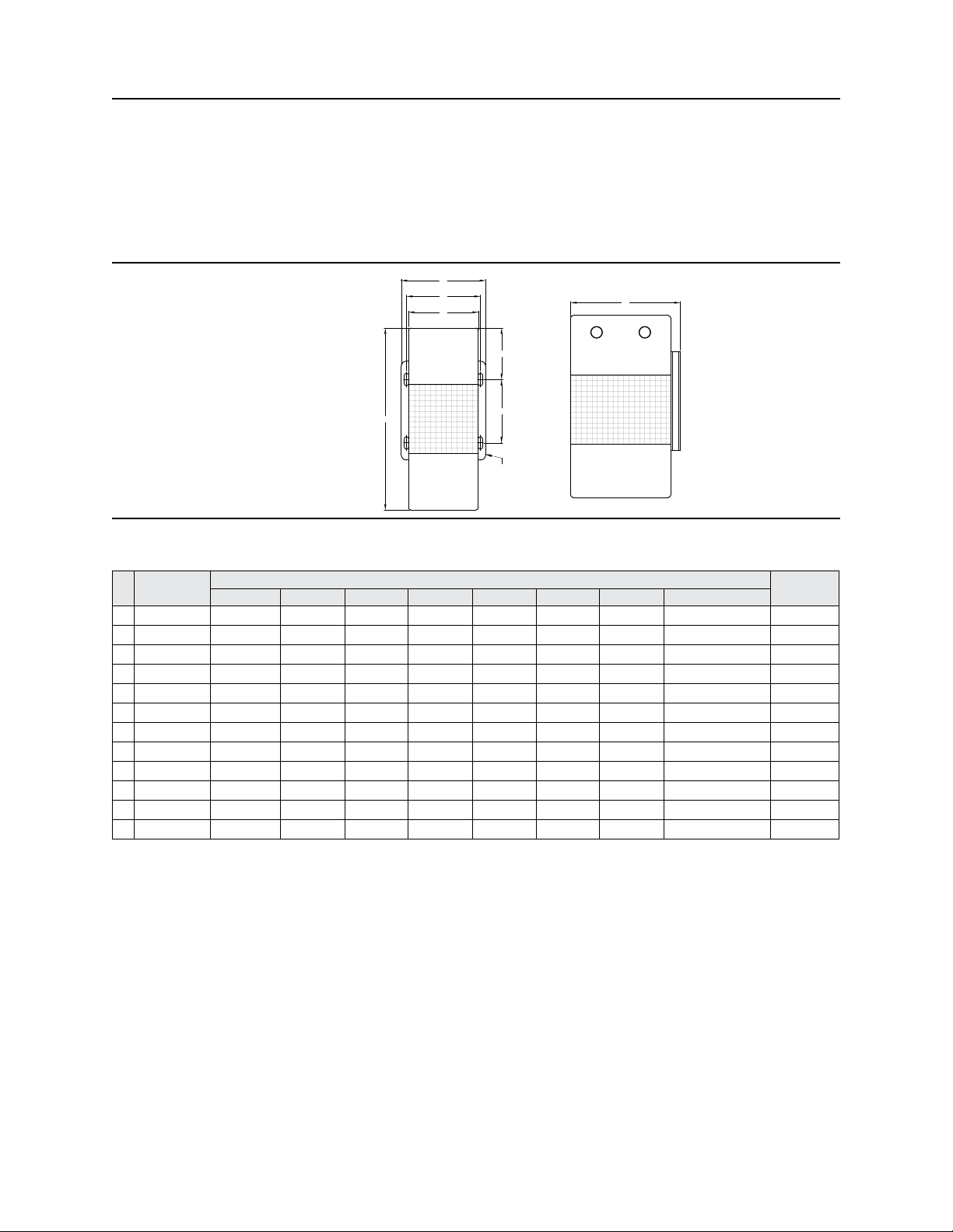
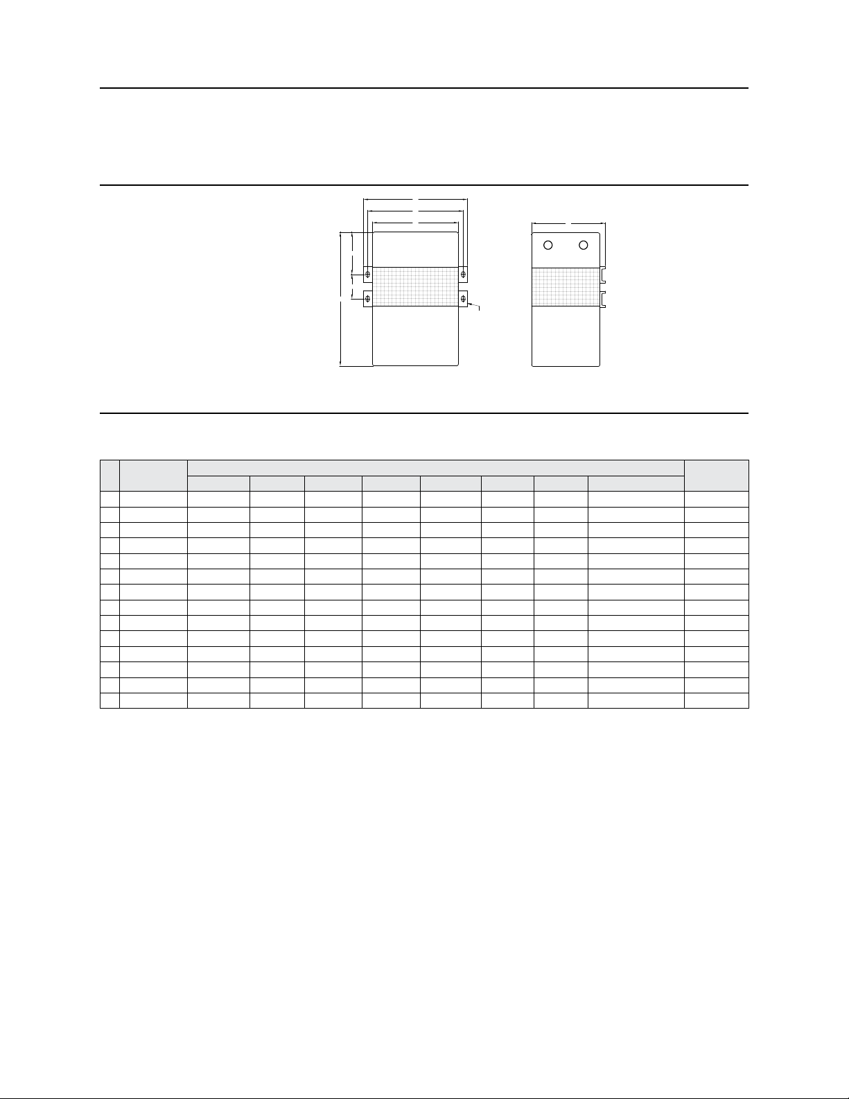
4.3 Mechanical Drawings & Dimensions
D
E
C
G
B
F
H
FIGURE 1
A
Table 2: Dimensions—Figure 1
Catalog
Hz
Number
60 63-23-112-4 8.62 [219] 5.19 [132] 3.31 [84] 4.00 [102] 3.50 [89] 3.00 [76] 2.90 [74] 0.22 x 0.59 [6 x 15] 15 [6.80]
50 63-23-612-8 9.09 [231] 7.44 [189] 4.50 [114] 5.39 [137] 4.76 [121] 4.13 [105] 2.17 [55] 0.31 x 0.69 [8 x 18] 18 [8.08]
60 63-23-125-4 9.88 [251] 7.44 [189] 4.50 [114] 5.62 [143] 4.76 [121] 4.13 [105] 3.06 [78] 0.31 x 0.69 [8 x 18] 27 [12.25]
50 63-23-625-8 10.59 [269] 7.44 [189] 4.50 [114] 5.39 [137] 4.76 [121] 4.13 [105] 2.17 [55] 0.31 x 0.69 [8 x 18] 27 [12.24]
60 63-23-150-8 12.69 [322] 6.44 [164] 7.78 [198] 9.00 [229] 8.12 [206] 5.62 [143] 3.06 [78] 0.38 x 0.81 [10 x 21] 37 [16.78]
60 63-31-150-8 12.69 [322] 6.44 [164] 7.78 [198] 9.00 [229] 8.12 [206] 5.62 [143] 3.06 [78] 0.38 x 0.81 [10 x 21] 38 [17.24]
50 63-23-650-8 13.27 [337] 6.44 [164] 7.78 [198] 9.00 [229] 8.12 [206] 5.62 [143] 3.58 [91] 0.38 x 0.81 [10 x 21] 40 [18.14]
60 63-23-175-8 13.69 [348] 6.44 [164] 7.78 [198] 9.00 [229] 8.12 [206] 5.62 [143] 3.06 [78] 0.38 x 0.81 [10 x 21] 52 [23.59]
60 63-23-210-8 16.75 [425] 6.44 [164] 7.78 [198] 9.00 [229] 8.12 [206] 5.62 [143] 5.25 [133] 0.38 x 0.81 [10 x 21] 62 [28.12]
60 63-23-210-C8 16.75 [425] 6.79 [172] 7.78 [198] 9.00 [229] 8.12 [206] 5.62 [143] 5.25 [133] 0.38 x 0.81 [10 x 21] 62 [28.12]
60 63-32-210-8 16.75 [425] 6.44 [164] 7.78 [198] 9.00 [229] 8.12 [206] 5.62 [143] 5.25 [133] 0.38 x 0.81 [10 x 21] 62 [28.12]
50 63-23-710-8 17.95 [456] 6.79 [172] 7.78 [198] 9.00 [229] 8.12 [206] 5.62 [143] 5.83 [148] 0.38 x 0.81 [10 x 21] 62 [28.12]
Dimensions in inches [mm]
Ship Weight
lb. [kg]A B C D E F G H
Page: 6
Page 7
MCR Hardwired Series – 50 Hz & 60 Hz
A272-282 Rev. 4 02/2020
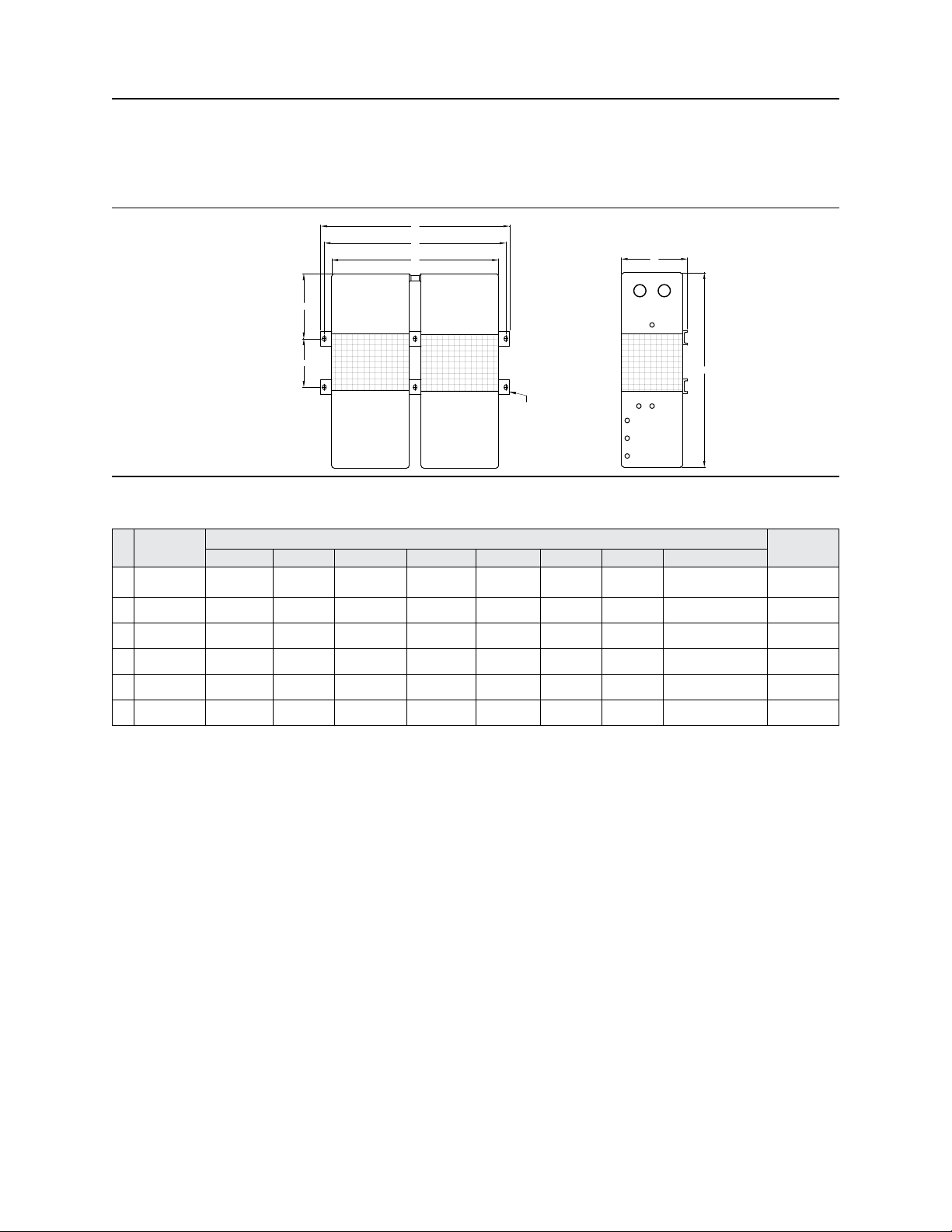
D
E
C
F G
A
H
FIGURE 2
Table 3: Dimensions—Figure 2
Catalog
Hz
Number
60 63-23-215-8 16.44 [418] 9.03 [229] 10.56 [268] 12.75 [324] 11.75 [298] 3.00 [76] 5.19 [132] 0.44 x 0.69 [11 x 18] 95 [43.10]
60 63-23-215-C8 16.44 [418] 9.37 [238] 10.56 [268] 12.75 [324] 11.75 [298] 3.00 [76] 5.19 [132] 0.44 x 0.69 [11 x 18] 95 [43.10]
60 63-23-220-8 17.31 [440] 9.03 [229] 10.56 [268] 12.75 [324] 11.75 [298] 3.88 [99] 5.19 [132] 0.44 x 0.69 [11 x 18] 109 [49.44]
60 63-23-220-C8 17.31 [440] 9.37 [238] 10.56 [268] 12.75 [324] 11.75 [298] 3.88 [99] 5.19 [132] 0.44 x 0.69 [11 x 18] 109 [49.44]
60 63-32-220-8 17.31 [440] 9.03 [229] 10.56 [268] 12.75 [324] 11.75 [298] 3.88 [99] 5.19 [132] 0.44 x 0.69 [11 x 18] 109 [49.44]
50 63-23-720-8 17.60 [447] 9.37 [238] 10.56 [268] 12.75 [324] 11.75 [298] 4.21 [107] 5.00 [127] 0.44 x 0.69 [11 x 18] 112 [50.81]
60 63-23-230-8 18.69 [475] 9.03 [229] 10.56 [268] 12.75 [324] 11.75 [298] 5.25 [133] 5.19 [132] 0.44 x 0.69 [11 x 18] 142 [64.41]
60 63-23-230-C8 18.69 [475] 9.37 [238] 10.56 [268] 12.75 [324] 11.75 [298] 5.25 [133] 5.19 [132] 0.44 x 0.69 [11 x 18] 142 [64.41]
60 63-32-230-8 18.69 [475] 9.03 [229] 10.56 [268] 12.75 [324] 11.75 [298] 5.25 [133] 5.19 [132] 0.44 x 0.69 [11 x 18] 142 [64.41]
50 63-23-730-8 26.65 [677] 9.37 [238] 10.59 [269] 12.75 [324] 11.75 [298] 6.06 [154] 3.70 [94] 0.44 x 0.69 [11 x 18] 160 [72.59]
60 63-23-250-8 28.19 [716] 9.03 [229] 10.56 [268] 12.75 [324] 11.75 [298] 8.25 [210] 8.88 [226] 0.44 x 0.69 [11 x 18] 222 [100.70]
60 63-23-250-C8 28.19 [716] 9.37 [238] 10.56 [268] 12.75 [324] 11.75 [298] 8.25 [210] 8.88 [226] 0.44 x 0.69 [11 x 18] 222 [100.70]
60 63-29-250-8 28.19 [716] 9.03 [229] 10.56 [268] 12.75 [324] 11.75 [298] 8.25 [210] 8.88 [226] 0.44 x 0.69 [11 x 18] 222 [100.70]
50 63-23-750-8 30.00 [762] 9.37 [238] 10.59 [269] 12.76 [324] 11.75 [298] 9.37 [238] 3.70 [94] 0.44 x 0.69 [11 x 18] 242 [109.79]
Dimensions in inches [mm]
B
Ship Weight
lb. [kg]A B C D E F G H
Page: 7
Page 8
MCR Hardwired Series – 50 Hz & 60 Hz
A272-282 Rev. 4 02/2020
D
E
C
B
F G
H
A
FIGURE 3
Table 4: Dimensions—Figure 3
Catalog
Hz
Number
60 63-28-275-8 26.56 [675] 9.03 [229] 22.81 [579] 25.81 [656] 24.81 [630] 6.62 [168] 8.88 [226] 0.44 x 0.69 [11 x 18] 362 [164.20]
60 63-29-275-8 26.56 [675] 9.03 [229] 22.81 [579] 25.81 [656] 24.81 [630] 6.62 [168] 8.88 [226] 0.44 x 0.69 [11 x 18] 362 [164.20]
50 63-28-775-8 27.99 [711] 9.37 [238] 24.49 [622] 25.81 [656] 24.81 [630] 7.36 [187] 3.70 [94] 0.44 x 0.69 [11 x 18] 390 [176.94]
60 63-28-310-8 28.19 [716] 9.03 [229] 22.81 [579] 25.81 [656] 24.81 [630] 8.25 [210] 8.88 [226] 0.44 x 0.69 [11 x 18] 446 [202.30]
60 63-29-310-8 28.19 [716] 9.03 [229] 22.81 [579] 25.81 [656] 24.81 [630] 8.25 [210] 8.88 [226] 0.44 x 0.69 [11 x 18] 446 [202.30]
50 63-28-810-8 30.00 [762] 9.37 [238] 24.49 [622] 25.81 [656] 24.81 [630] 9.37 [238] 3.70 [94] 0.44 x 0.69 [11 x 18] 486 [220.50]
Dimensions in inches [mm]
Ship Weight
lb. [kg]A B C D E F G H
Page: 8
Page 9

MCR Hardwired Series – 50 Hz & 60 Hz
A272-282 Rev. 4 02/2020
D
E
C
B
F G
H
A
FIGURE 4
Table 5: Dimensions—Figure 4
Catalog
Hz
Number
60 63-28-275-8 26.56 [675] 9.03 [229] 22.81 [579] 25.81 [656] 24.81 [630] 6.62 [168] 8.88 [226] 0.44 x 0.69 [11 x 18] 362 [164.20]
60 63-29-275-8 26.56 [675] 9.03 [229] 22.81 [579] 25.81 [656] 24.81 [630] 6.62 [168] 8.88 [226] 0.44 x 0.69 [11 x 18] 362 [164.20]
50 63-28-775-8 27.99 [711] 9.37 [238] 24.49 [622] 25.81 [656] 24.81 [630] 7.36 [187] 3.70 [94] 0.44 x 0.69 [11 x 18] 390 [176.94]
60 63-28-310-8 28.19 [716] 9.03 [229] 22.81 [579] 25.81 [656] 24.81 [630] 8.25 [210] 8.88 [226] 0.44 x 0.69 [11 x 18] 446 [202.30]
60 63-29-310-8 28.19 [716] 9.03 [229] 22.81 [579] 25.81 [656] 24.81 [630] 8.25 [210] 8.88 [226] 0.44 x 0.69 [11 x 18] 446 [202.30]
50 63-28-810-8 30.00 [762] 9.37 [238] 24.49 [622] 25.81 [656] 24.81 [630] 9.37 [238] 3.70 [94] 0.44 x 0.69 [11 x 18] 486 [220.50]
Dimensions in inches [mm]
Ship Weight
lb. [kg]A B C D E F G H
Page: 9
Page 10
MCR Hardwired Series – 50 Hz & 60 Hz
A272-282 Rev. 4 02/2020
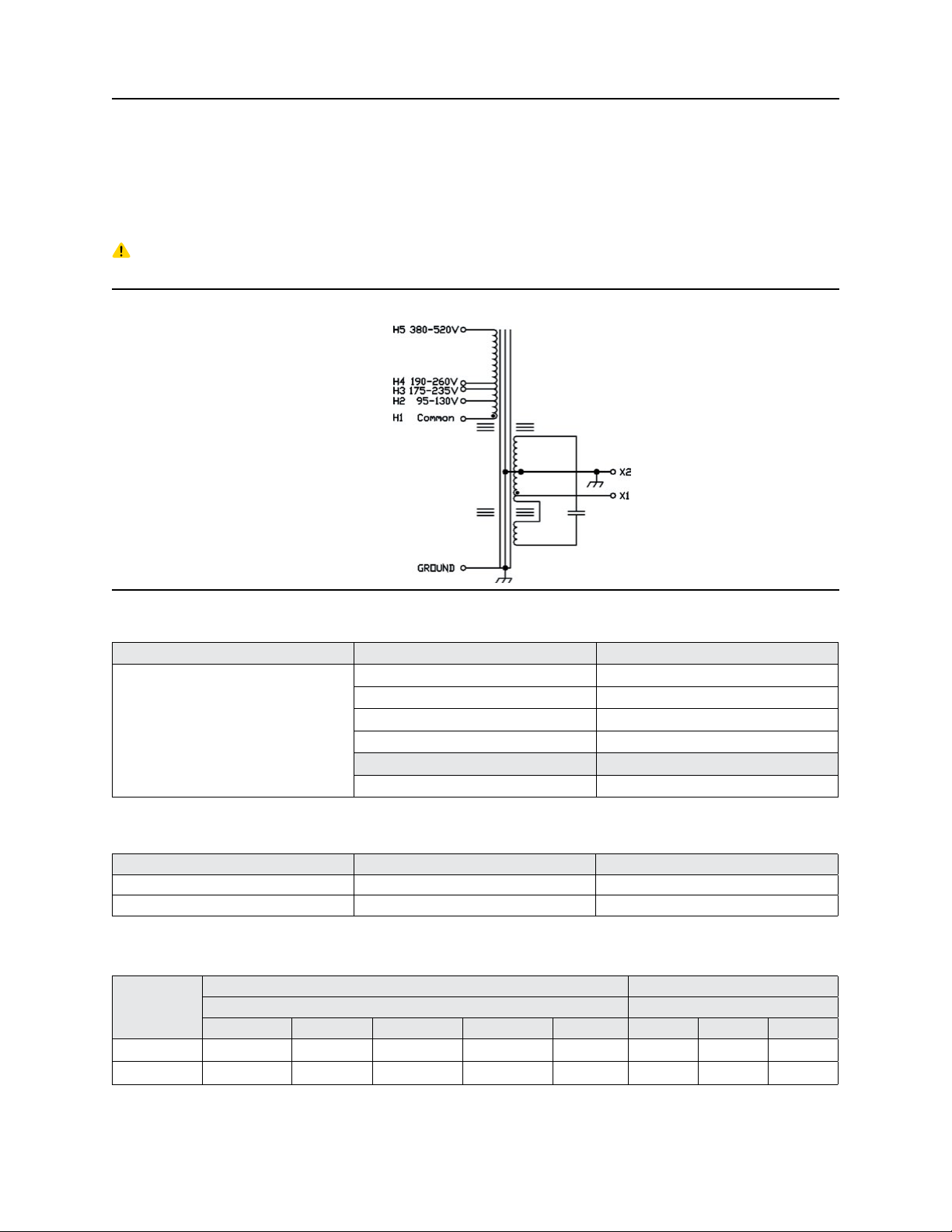
4.4 Electrical
CAUTION! All hardwired units should be installed in accordance with local and national electrical codes.
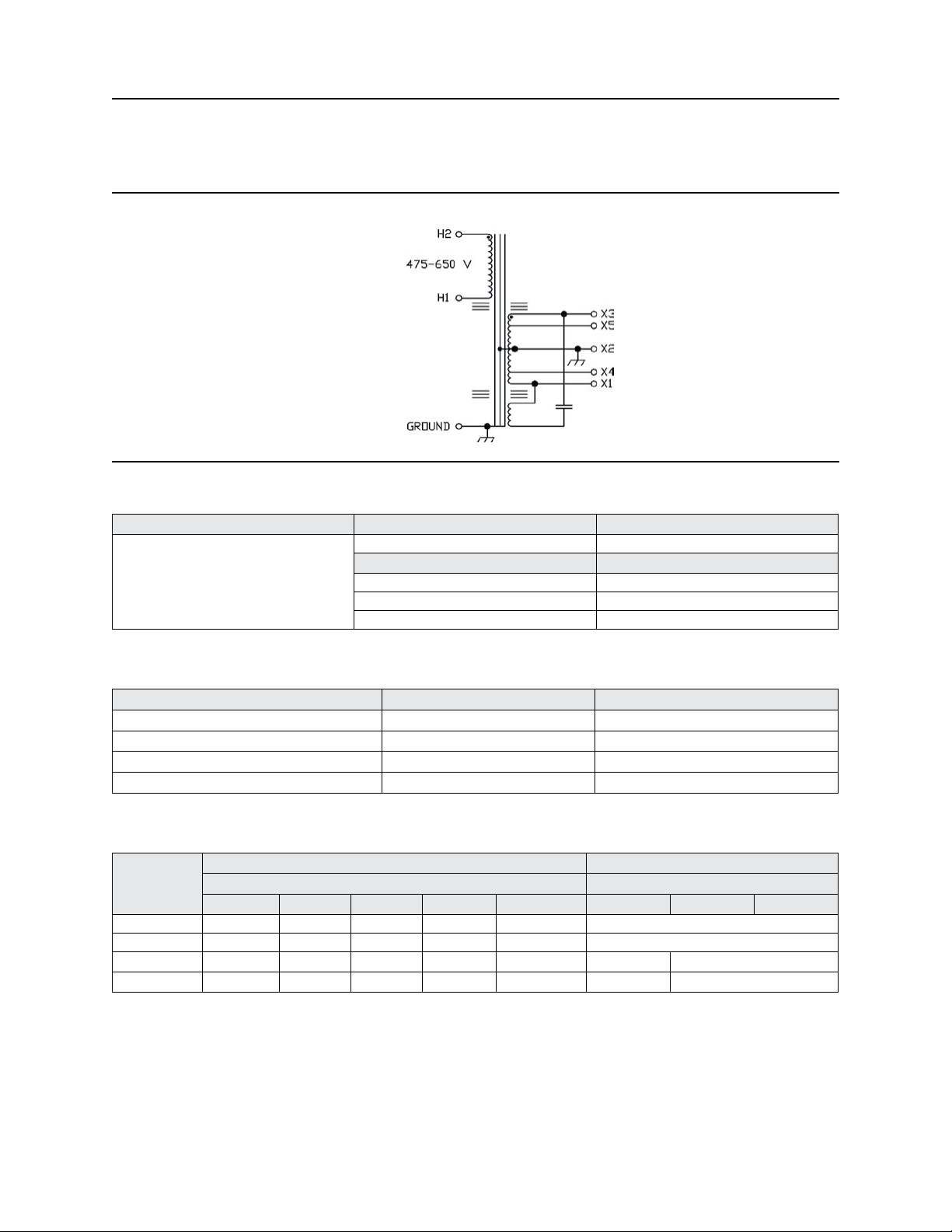
For Catalog Numbers 63-23-112-4 & 63-23-125-4
60 Hz
FIGURE 5
Table 6: Electrical Connections—Figure 5
Catalog Number Primary Voltage Connect Lines to
120 H1 and H2
208 H1 and H3
63-23-112-4
63-23-125-4
240 H1 and H4
480 H1 and H5
Secondary Voltage Connect Lines to
120 X1 and X2
Table 7: Product Parameters Table 7: Product Parameters
Catalog Number VA BTU Output at Full load, +40°C Ambient
63-23-112-4 120 136
63-23-125-4 250 225
Table 8: Fusing & Wiring
Required Circuit Protection/Minimum Gauge for 90°C Wire Minimum Gauge for 90°C Wire
Catalog
Number
63-23-112-4 3 A/14 AWG 3 A/14 AWG 3 A/14 AWG 1 A/14 AWG --- 14 AWG --- --63-23-125-4 6 A/14 AWG 3 A/14 AWG 3 A/14 AWG 1 A/14 AWG --- 14 AWG --- ---
Input Voltage Output Voltage
95–130 175–235 190–260 380–520 475–650 120 208 240
Page: 10
Page 11
MCR Hardwired Series – 50 Hz & 60 Hz
A272-282 Rev. 4 02/2020
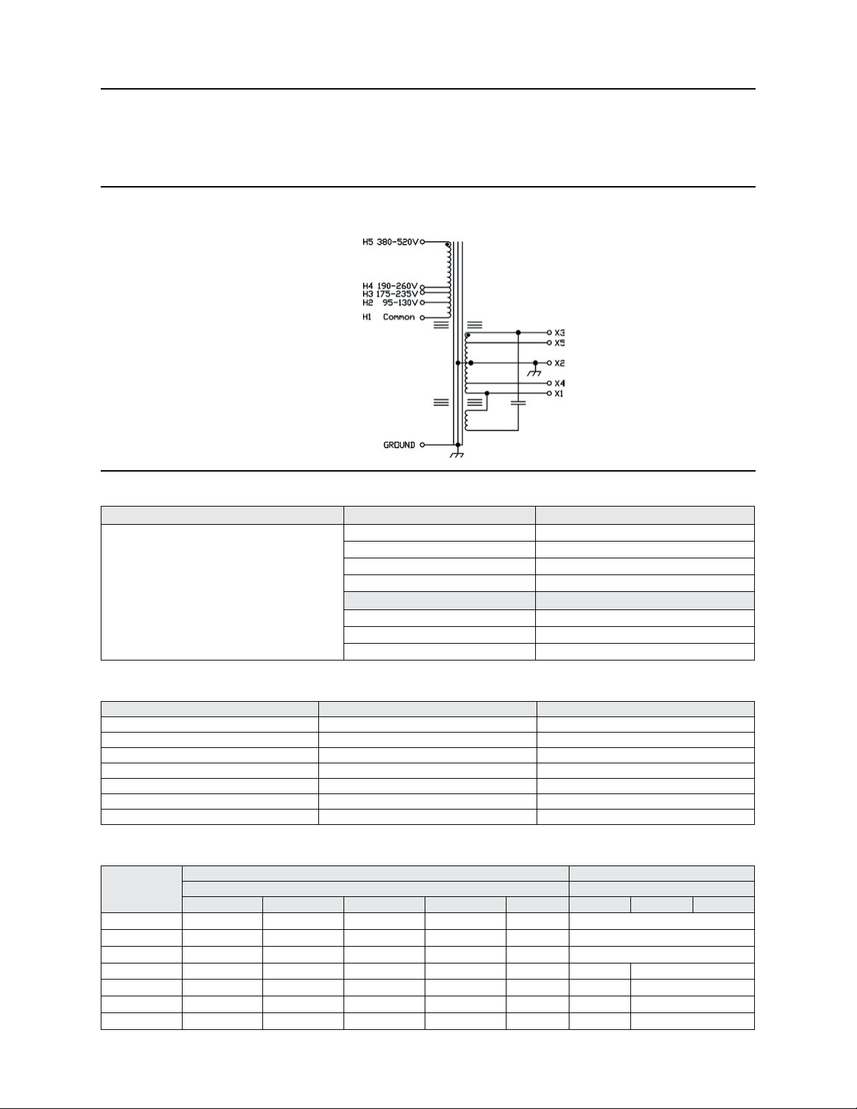
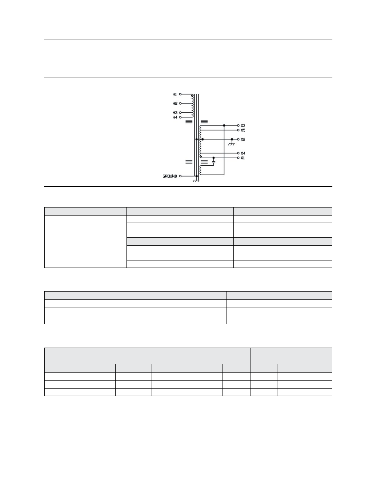
For Catalog Numbers 63-23-150-8, 63-23-175-8, 63-23-210-8*, 63-23-215-8*, 63-23-220-8*,
63-23-230-8*, & 63-23-250-8*
60 Hz
FIGURE 6
Table 9: Electrical Connections—Figure 6
Catalog Numbers Primary Voltage Connect Lines to
120 H1 and H2
63-23-150-8
63-23-175-8
63-23-210-8
63-23-215-8*
63-23-220-8*
63-23-230-8*
63-23-250-8*
*
208 H1 and H3
240 H1 and H4
480 H1 and H5
Secondary Voltage Connect Lines to
120 X1 and X2
208 X4 and X5
240 X1 and X3
Table 10: Product Parameters
Catalog Number VA BTU Output at Full load, +40°C ambient
63-23-150-8 500 280
63-23-175-8 750 444
63-23-210-8* 1000 519
63-23-215-8* 1500 686
63-23-220-8* 2000 1229
63-23-230-8* 3000 1331
63-23-250-8* 5000 2117
Table 11: Fusing & Wiring
Required Circuit Protection/Minimum Gauge for 90°C Wire Minimum Gauge for 90°C Wire
Catalog
Number
63-23-150-8 10 A/14 AWG 6 A/14 AWG 6 A/14 AWG 3 A/14 AWG --- 14 AWG
63-23-175-8 15 A/14 AWG 10 A/14 AWG 6 A/14 AWG 3 A/14 AWG --- 14 AWG
63-23-210-8
63-23-215-8
63-23-220-8
63-23-230-8
63-23-250-8
*Canadian option: For cULus units, replace “– 8” sufx (UL only model) with “– C8” (cULus model).
**Leads in the wiring compartment must have 105°C sleeving.
Input Voltage Output Voltage
95–130 175–235 190–260 380–520 475–650 120 208 240
* 15 A/14 AWG 10 A/14 AWG 10 A/14 AWG 6 A/14 AWG --- 14 AWG
* 25 A/10 AWG 15 A/14 AWG 15 A/14 AWG 10 A/14 AWG --- 12 AWG 14 AWG
* 30 A/10 AWG 20 A/12 AWG 15 A/14 AWG 10 A/14 AWG --- 10 AWG 14 AWG
* 45 A/8 AWG 25 A/10 AWG 25 A/10 AWG 15 A/14 AWG --- 8 AWG 12 AWG
* 80 A/4 AWG 40 A/8 AWG 40 A/8 AWG 20 A/12 AWG --- 8 AWG** 10 AWG
Page: 11
Page 12
MCR Hardwired Series – 50 Hz & 60 Hz
A272-282 Rev. 4 02/2020
For Catalog Numbers 63-31-150-8, 63-32-210-8, 63-32-220-8, & 63-32-230-8
60 Hz
FIGURE 7
Table 12: Electrical Connections—Figure 7
Catalog Number Primary Voltage Connect Lines to
600 H1 and H2
63-31-150-8
63-32-210-8
63-32-220-8
63-32-230-8
Secondary Voltage Connect Lines to
120 X1 and X2 OR X3 and X2
208 X4 and X5
240 X1 and X3
Table 13: Product Parameters
Catalog Number VA BTU Output at Full load, +40°C Ambient
63-31-150-8 500 280
63-32-210-8 1000 519
63-32-220-8 2000 1229
63-32-230-8 3000 1331
Table 14: Fusing & Wiring
Required Circuit Protection/Minimum Gauge for 90°C Wire Minimum Gauge for 90°C Wire
Catalog
Number
63-31-150-8 --- --- --- --- 2 A/14 AWG 14 AWG
63-32-210-8 --- --- --- --- 3 A/14 AWG 14 AWG
63-32-220-8 --- --- --- --- 10 A/14 AWG 10 AWG 14 AWG
63-32-230-8 --- --- --- --- 15 A/12 AWG 8 AWG 12 AWG
Input Voltage Output Voltage
95–130 175–235 190–260 380–520 475–650 120 208 240
Page: 12
Page 13
MCR Hardwired Series – 50 Hz & 60 Hz
For Catalog Numbers 63-28-275-8, 63-28-310-8, & 63-28-315-8
60 Hz
FIGURE 8
Table 15: Electrical Connections—Figure 8
Catalog Number Primary Voltage Connect Lines to
208 H2 and H3
240 H2 and H4
63-28-275-8
63-28-310-8
63-28-315-8
480 H1 and H4
Secondary Voltage Connect Lines to
120 X1 and X2 OR X3 and X2
208 X4 and X5
240 X1 and X3
A272-282 Rev. 4 02/2020
Table 16: Product Parameters
Catalog Number VA BTU Output at Full load, +40°C Ambient
63-28-275-8 7500 2407
63-28-310-8 10000 3209
63-28-315-8 15000 4813
Table 17: Fusing & Wiring
Required Circuit Protection/Minimum Gauge for 90°C Wire Minimum Gauge for 90°C Wire
Catalog
Number
63-28-275-8 --- 60 A/6 AWG 60 A/8 AWG 30 A/10 AWG --- 4 AWG 8 AWG 8 AWG
63-28-310-8 --- 80 A/3 AWG 80 A/4 AWG 40 A/8 AWG --- 3 AWG 6 AWG 8 AWG
63-28-315-8 --- 125 A/1 AWG 110 A/2 AWG 60 A/4 AWG --- 0 AWG 4 AWG 4 AWG
Input Voltage Output Voltage
95–130 175–235 190–260 380–520 475–650 120 208 240
Page: 13
Page 14
MCR Hardwired Series – 50 Hz & 60 Hz
A272-282 Rev. 4 02/2020
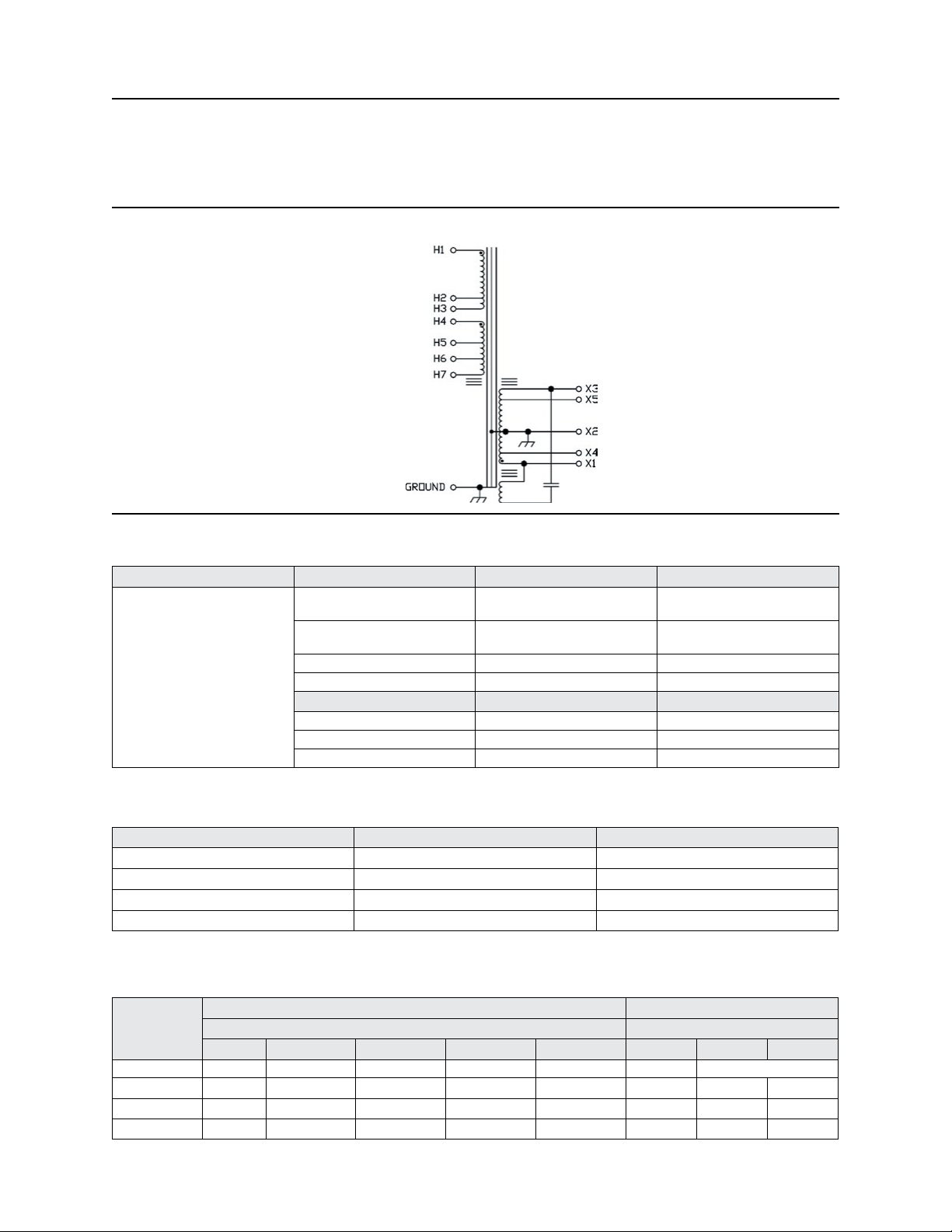
For Catalog Numbers 63-29-250-8, 63-29-275-8, 63-29-310-8, & 63-29-315-8
60 Hz
FIGURE 9
Table 18: Electrical Connections—Figure 9
Catalog Number Primary Voltage Interconnect Connect Lines to
H1 to H4
H2 to H5
H1 to H4
H3 to H6
H1 and H5
H1 and H6
63-29-250-8
63-29-275-8
63-29-310-8
63-29-315-8
208
240
480 H3 to H4 H1 and H6
600 H3 to H4 H1 and H7
Secondary Voltage Interconnect Connect Lines to
120 --- X1 and X2 OR X3 and X2
208 --- X4 and X5
240 --- X1 and X3
Table 19: Product Parameters
Catalog Number VA BTU Output at Full load, +40°C Ambient
63-29-250-8 5000 2117
63-29-275-8 7500 2407
63-29-310-8 10000 3209
63-29-315-8 15000 4813
Table 20: Fusing & Wiring
Catalog
Number
63-29-250-8 --- 40 A/8 AWG 40 A/8 AWG 20 A/12 AWG 15 A/12 AWG 8 AWG
63-29-275-8 --- 60 A/6 AWG 60 A/6 AWG 30 A/10 AWG 25 A/10 AWG 4 AWG 4 AWG 4 AWG
63-29-310-8 --- 80 A/3 AWG 80 A/4 AWG 40 A/8 AWG 30 A/10 AWG 3 AWG 6 AWG 8 AWG
63-29-315-8 --- 125 A/1 AWG 110 A/2 AWG 60 A/4 AWG 50 A/8 AWG 0 AWG 4 AWG 4 AWG
**Leads in the wiring compartment must have 105°C sleeving.
Page: 14
Required Circuit Protection/Minimum Gauge for 90°C Wire Minimum Gauge for 90°C Wire
Input Voltage Output Voltage
95–130 175–235 190–260 380–520 475–650 120 208 240
** 10 AWG
Page 15

MCR Hardwired Series – 50 Hz & 60 Hz
A272-282 Rev. 4 02/2020
For Catalog Numbers 63-23-612-8, 63-23-625-8, 63-23-650-8, 63-23-710-8, 63-23-720-8, 63-23-730-8,
63-23-750-8, 63-28-775-8, 63-28-810-8, 63-28-815-8
50 Hz
FIGURE 10
Table 21: Electrical Connections—Figure 10
Unit Input Volts Input Terminals Jumper Connection Output Connection
90-130 H1-H4 (H1-H3) (H2-H4)
250 to 5000 VA
7500 VA
10000-15000 VA
182-260 H1-H4 (H2-H3)
310-450 H1-H5 (H2-H3)
180-260 H1-H5 (H1-H3) (H2-H5)
310-450 H1-H4 (H2-H3)
180-260 H1-H4 (H2-H3)
310-450 H1-H5 (H2-H3)
(All Models)
110-X1-X2 OR X2-X3
120 X4-X2 OR X2-X5
220-X1-X3
240 X4-X5
Table 22: Product Parameters
Catalog Number VA BTU Output at Full load, +40°C Ambient
63-23-612-8 120 85
63-23-625-8 250 160
63-23-650-8 500 300
63-23-710-8 1000 525
63-23-720-8 2000 825
63-23-730-8 3000 1263
63-23-750-8 5000 2105
63-28-775-8 7500 4105
63-28-810-8 10000 4210
63-28-815-8 15000 4815
Page: 15
Page 16

MCR Hardwired Series – 50 Hz & 60 Hz
A272-282 Rev. 4 02/2020
Table 23: Fusing & Wiring
Required Circuit Protection/Minimum Gauge for 90°C Wire Minimum Gauge for 90°C Wire
Catalog
Number
63-23-612-8 3 A/1,0 mm
63-23-625-8 6 A/1,0 mm
63-23-650-8 10 A/1,5 mm
63-23-710-8 15 A/2,5 mm
63-23-720-8 30 A/6,0 mm
63-23-730-8 45 A/16,0 mm
63-23-750-8 80 A/25,0 mm
63-28-775-8 --- 60 A/16,0 mm
63-28-810-8 --- 80 A/25,0 mm
63-28-815-8 --- 110 A/50,0 mm
Input Voltage Output Voltage
110–120 220–240 380–415 110–120 220–240
2
2
2
2
2
2
2
1,5 A/1,0 mm
3 A/1,0 mm
6 A/1,0 mm
10 A/1,5 mm
15 A/2,5 mm
25 A/4,0 mm
40 A/10,0 mm
2
2
2
0,8 A/1,0 mm
1 A/1,0 mm
3 A/1,0 mm
2
2
2
2
2
2
2
6 A/1,0 mm
10 A/1,5 mm
15 A/2,5 mm
20 A/4,0 mm
30 A/6,0 mm
40 A/10,0 mm
60 A/16,0 mm
2
2
2
2
2
2
2
2
2
2
1,0 mm 1,0 mm
1,0 mm 1,0 mm
1,0 mm 1,0 mm
1,5 mm 1,0 mm
4,0 mm 1,5 mm
6,0 mm 2,5 mm
16,0 mm 4,0 mm
25,0 mm 10,0 mm
35,0 mm 16,0 mm
45,0 mm 25,0 mm
Page: 16
Page 17

MCR Hardwired Series – 50 Hz & 60 Hz
In Grounded WYE
A272-282 Rev. 4 02/2020
5.0 Parallel & Three-Phase Connections
5.1 Parallel Operation
Units of the same SolaHD catalog number may be connected in parallel to obtain a larger load capacity. Both
input and output connections must be made in parallel (see Figure 11). The SolaHD catalog number must end
in -8 or -C8 and must be larger than 1 kVA. No portable units can be paralleled.
All input and output paralleling wires must be tied together in an external paralleling “box” provided by the
user. Do not attempt to jumper the wires of one unit to the terminal block of the other unit. The terminal
block may not be rated to carry the total currents of both units. The input of each unit must be properly and
separately fused.
CAUTION! Failure to adhere to these requirements may damage the windings.
For units smaller than 5 kVA: When connecting in parallel the 208 Volt windings, other output voltage ratings
(120 V, 240 V) can’t be paralleled at the same time and vice versa. It is suggested that the installer remove X2
grounding on each unit, then connect X2 from each unit to one location and ground at that location only.
5.2 Three-Phase Connection Operation
Loads requiring 4-wire WYE connection may be served by three ferroresonant power conditioners with the
same SolaHD catalog number. The inputs must be connected in Delta. Input fuses must be connected in the
primary of each unit, not in the three-phase lines. The outputs must be connected in WYE with the neutral
solidly connected to a WYE load. Alternatively, these three outputs may serve three independent single-phase
loads. Phase angles may vary somewhat from 120 degrees even with balanced loading.
This circuit arrangement is not intended to serve single-phase line-to-line loading or three-phase Delta
loading. Outputs must serve three independent, single-phase loads of the same total Volt-Amphere (VA)
rating. Connections should be made in one of two ways as shown in Figure 11.
The outputs of the unit are isolated from the input lines. Voltage generated by internal leakage currents will
occur with respect to ground, which can have undesirable effects in electronic equipment. Therefore, if circuit
“B” is used, it is suggested that the installer remove X2 grounding on -8 units, then connect all X2 from each
phase to one location and ground at that location only. This is not required for circuit “A” and will not affect
regulation or the ability to reject power line noise or transients. s.
B
A
CV
Trans
Load
(A) Isolated Single-Phase Loads
A
CV
Trans
Load
B
C
CV
Trans
Load
C
Ac Single-Phase
Input
Input
Unit A
Output
FIGURE 11
CV
Trans
Load
(B) Separte Single-Phase Loads
CV
Trans
Load
CV
Trans
Load
Input
Unit B
Output
Page: 17
Page 18

MCR Hardwired Series – 50 Hz & 60 Hz
A272-282 Rev. 4 02/2020
6.0 Operating Notes & Data
DANGER! High voltages are present inside the unit. Do not reach inside while it is energized. To measure
voltage, de-energize the unit, connect the meter, and then re-energize the unit.
6.1 Checking with Voltmeters
All input and output voltage measurements should be made with a true RMS voltmeter. A certain amount of
harmonics in the output may cause other types—particularly rectier types—to give inaccurate indications.
6.2 Load Regulation
Changes in output voltage resulting from changes in resistive loads, from no load to full load (100% pF), are
approximately 4%.
6.3 Effect of Load Power Factor
“Median” value of output voltage will vary from the label rating if the load has a power factor different
from the unit’s design. Load regulation will also be greater as the inductive load power factor is decreased.
However, the resulting median values of output voltage will be regulated against supply line changes at any
reasonable load or load power factor.
FIGURE 12
6.4 Operation with Switch-Mode Power Supplies
If an MCR is used as a source for a switch-mode power supply, a slight amount of ringing may be noticed on
the sine wave output of the unit at half cycle intervals for a short duration. This ringing occurs at the point
when the switch-mode power supply current demand drops to zero. The ringing need not be a cause for
concern since it is of relatively low magnitude and frequency. Both series have been tested with a variety of
switch-mode power supplies and it has been determined that the ringing does not affect the dc outputs, nor
has it been found to degrade the components of any switch-mode power supply.
Page: 18
Page 19

MCR Hardwired Series – 50 Hz & 60 Hz
A272-282 Rev. 4 02/2020
6.5 Effect of Frequency
Changes in the frequency of the supply voltage will be directly reected in the output voltage. A change of
about 1.8% in output voltage will occur for every 1% change in input frequency, and in the same direction as
the frequency change.
6.6 Response Time
An important advantage of the SolaHD principle of static magnetic regulation is its exceedingly fast response
time compared with other types of ac regulators. Transient changes in supply voltage are usually corrected
with 1-1/2 cycles or less; the output voltage will not uctuate more than a few percent.
6.7 Input Characteristics
The MCR’s transformer includes a resonant circuit, which is energized whether it is serving a load or not.
Therefore, the input current at no load is approximately 35% of the full-load level, even at light or no load.
Input power factor will average 90–100% at full load, but may drop to about 75% at half load and 25% at no
load. In any case, it is always leading.
6.8 Current Limitations
When the load is increased beyond the MCR’s rated value, a point is reached where the output voltage
suddenly collapses and will not regain its normal value until the load is partially released. Under short-circuit
conditions, the load current is limited to approximately twice of the rated full-load value, and the input power
to less than 10% of normal. The unit will protect both itself and its load against damage from excessive fault
currents. Fusing of load circuits is not necessary.
6.9 Operation with Motor Loads
Because of the current-limiting effect described above, special attention should be given to motor
applications. In general, the regulator must have a load rating nearly equal to the maximum power drawn
during the starting cycle. This may run from two to eight times the normal (running) rating of the motor. In
doubtful cases, it is advisable to measure the actual starting current.
Page: 19
Page 20

MCR Hardwired Series – 50 Hz & 60 Hz
A272-282 Rev. 4 02/2020
7.0 Service & Maintenance
7.1 Service & Maintenance
The unit is a simple, rugged device with no moving parts. Routine service and/or maintenance is not required.
If a problem does occur, please refer to “8.0 Troubleshooting” or contact SolaHD Technical Support for
assistance.
7.2 Field Replacement of Capacitors
Capacitors used in our units are the highest commercial grade, with each one given a rigid acceptance test
upon receipt. SolaHD guarantees free replacement of any capacitors which fail within one year of sale. Older
units can be replaced at a moderate charge.
NOTE: It may be possible to test and identify defective capacitors in the eld. Please contact SolaHD Technical
Support at 1.800.377.4384 or 1.847.268.6651 for further assistance.
8.0 Troubleshooting
Table 24: Troubleshooting
Problem Action
Nominal voltage too high
Nominal voltage too low
Unit does not regulate closely
Output voltage is very low (20–60 V)
No output voltage
Transformer operating temperature
Unit is operating, but does not appear
to have the correct output
Support
Please contact SolaHD Technical Support at 1.800.377.4384/1.847.268.6651 or by e-mail at solahd.technicalservices@emerson.com
for further assistance.
1. The load may be considerably less than the full rating. See “6.2 Load Regulation”.
2. The load may have a leading power factor.
1. The load power factor may be lagging.
2. The unit may be slightly overloaded. See “6.8 Current Limitations”.
1. The unit may be slightly overloaded. See “6.8 Current Limitations”.
2. The actual line voltage swings may be outside the rate range of the unit, particularly on
the low side.
3. On varying loads, a certain amount of load regulation may be mixed with the line voltage
regulating action. See “6.2 Load Regulation”.
1. Unsuspected or unplanned overloads of substantial size may occur intermittently (motorstarting currents, solenoid inrush currents, etc.). See “6.8 Current Limitations”.
2. One or more capacitors in the regulator may be defective.
1. Check power source breakers or fuses.
2. Check input switch.
3. Check continuity between input terminals, and also between output terminals.
1. The transformer used in the unit is designed to operate at high ux density and relatively
high temperatures. After connection to the line for 30 minutes or so, the transformer core
structure may be too hot to touch with your bare hands. This is normal and should not
cause concern.
The steps below will usually establish whether the apparent poor performance is due to a
fault in the unit or to some peculiarity of the working load.
1. Disconnect the working load.
2. Connect a dummy load of lamps, heaters, or other resistive loads (substantially equal to
the full load rating of the regulator) directly across the output terminals.
3. Measure the output voltage of the regulator (using a true RMS type voltmeter) directly
across the output terminals.
Page: 20
Page 21

9.0 Specifications
Table 25: General Specifications
MCR Hardwired Series – 50 Hz & 60 Hz
A272-282 Rev. 4 02/2020
Phase
Frequency
Output Voltage Regulation
Output Harmonic Distortion
Eciency
Noise Reduction
Minimum Loading
Voltage Surge Suppression
Ambient Temperature
Humidity
Directives
Certications
UL 1012, CSA C22.2 No. 107.1
Warranty
Single
60 Hz 50 Hz
±3% for an input line variation of +10% to -20% ±5% for an input line variation of +10% to -20%
Less than 3% total RMS content at full load
Up to 92% at full load (typical) – model dependent
Common mode noise rejection exceeds 120 dB; Transverse noise rejection exceeds 60 dB
40%
Meets ANSI/IEEE C62.41 Category A & B waveforms (formerly IEEE 587-1980)
Operating: -20°C to +50°C; Storage: -20°C to +85°C
<95% non-condensing
RoHS compliant
Model Certification
63-23-112-4 cULus
63-23-612-8 cULus
63-23-125-4 cULus
63-23-625-8 cULus
63-23-150-8 cULus
63-23-650-8 cULus
63-23-175-8 cULus
63-23-210-8 UL
63-23-210-C8 cULus
63-23-710-8 cULus
63-23-215-8 UL
63-23-215-C8 cULus
63-23-220-8 UL
63-23-220-C8 cULus
63-23-720-8 cULus
63-23-230-8 UL
63-23-230-C8 cULus
63-23-730-8 cULus
63-23-250-8 UL
63-23-250-C8 cULus
63-23-750-8 cULus
63-28-775-8 cULus
63-28-810-8 cULus
63-28-815-8 cULus
63-28-275-8 UL
63-28-310-8 UL
63-28-315-8 UL
63-29-250-8 CSA
63-29-275-8 CSA
63-29-310-8 CSA
63-29-315-8 CSA
63-31-150-8 cULus
63-32-210-8 cULus
63-32-220-8 cULus
63-32-230-8 cULus
10 year limited warranty
Page: 21
Page 22

MCR Hardwired Series – 50 Hz & 60 Hz
A272-282 Rev. 4 02/2020
10.0 Warranty & Support
10.1 Warranty Information
Please refer to the “Terms & Conditions of Sale”.
10.2 Technical Support
Phone: 1.800.377.4384 or 1.847.268.6651
E-mail: solahd.technicalservices@emerson.com
Web site: www.solahd.com
While every precaution has been taken to ensure accuracy and completeness in this manual Appleton Grp LLC d/b/a Appleton Group assumes no
responsibility, and disclaims all liability for damages resulting from use of this information or for any errors or omissions.
Page: 22
Page 23

Série MCR câblée – 50 Hz et 60 Hz
Conditionneur de Puissance
A272-282
Rev. 4 02/2020
Page 24

Série MCR câblée – 50 Hz et 60 Hz
A272-282 Rev. 4 02/2020
SOMMAIRE
1.0 Consignes de sécurité importantes . . . . . . . . . . 26
2.0 Définitions des avertissements . . . . . . . . . . . . 26
3.0 Introduction . . . . . . . . . . . . . . . . . . . . . 26
4.0 Instructions d’installation . . . . . . . . . . . . . . . 27
4.1 Réception . . . . . . . . . . . . . . . . . . . . . . . . . . . . . . . . . . 27
4.2 Montage, ventilation et facteurs importants à considérer . . . . . . . . . . . 27
4.3 Dimensions et caractéristiques physiques . . . . . . . . . . . . . . . . . . . 28
4.4 Branchements électriques . . . . . . . . . . . . . . . . . . . . . . . . . . 32
5.0 Branchements en parallèle et branchements triphasés 39
5.1 Fonctionnement en parallèle . . . . . . . . . . . . . . . . . . . . . . . . . 39
5.2 Fonctionnement en branchement triphasé . . . . . . . . . . . . . . . . . . 39
6.0 Remarques et informations sur le fonctionnement. . . 40
6.1 Vérications à l’aide de voltmètres . . . . . . . . . . . . . . . . . . . . . . 40
6.2 Régulation de la charge . . . . . . . . . . . . . . . . . . . . . . . . . . . 40
6.3 Effets du facteur de puissance de charge . . . . . . . . . . . . . . . . . . . 40
6.4 Utilisation avec des alimentations à découpage . . . . . . . . . . . . . . . . 40
6.5 Effets de la fréquence . . . . . . . . . . . . . . . . . . . . . . . . . . . . 41
Page: 24
6.6 Temps de réponse . . . . . . . . . . . . . . . . . . . . . . . . . . . . . . 41
6.7 Caractéristiques de l’entrée . . . . . . . . . . . . . . . . . . . . . . . . . 41
6.8 Limitations du courant . . . . . . . . . . . . . . . . . . . . . . . . . . . . 41
6.9 Utilisation avec des charges de moteur . . . . . . . . . . . . . . . . . . . . 41
Page 25

SOMMAIRE
7.0 Dépannage et entretien . . . . . . . . . . . . . . . . 42
7.1 Dépannage et entretien . . . . . . . . . . . . . . . . . . . . . . . . . . . 42
7.2 Remplacement des condensateurs sur place . . . . . . . . . . . . . . . . . . 42
8.0 Dépannage . . . . . . . . . . . . . . . . . . . . . . 42
9.0 Spécifications . . . . . . . . . . . . . . . . . . . . . 43
10.0 Garantie et assistance . . . . . . . . . . . . . . . . 44
Série MCR câblée – 50 Hz et 60 Hz
A272-282 Rev. 4 02/2020
10.1 Informations relatives à la garantie . . . . . . . . . . . . . . . . . . . . . . 44
10.2 Assistance technique . . . . . . . . . . . . . . . . . . . . . . . . . . . . 44
Page: 25
Page 26

Série MCR câblée – 50 Hz et 60 Hz
A272-282 Rev. 4 02/2020
1.0 Consignes de sécurité importantes
Lire l’intégralité des instructions relatives à la sécurité, l’installation et le fonctionnement avant d’essayer
d’installer ou d’utiliser l’appareil.
!
DANGER
Des tensions élevées sont présentes dans l’appareil. Ne pas toucher l’intérieur lorsqu’il est sous tension.
Cet appareil contient des pièces ne pouvant pas être réparées par l’utilisateur.
2.0 Warnings Defined
DANGER
Indicates an imminently hazardous situation that, if not avoided, will result in death or serious injury. This
signal word is limited to the most extreme situations.
MISE EN GARDE
Indique une situation potentiellement dangereuse susceptible d’entraîner des blessures graves, voire
mortelles, si elle n’est pas évitée.
ATTENTION
Signale une situation de danger potentiel susceptible d’entraîner des blessures légères ou modérées si elle
n’est pas évitée. Ce terme peut aussi servir à mettre en garde contre des pratiques dangereuses.
3.0 Introduction
Le régulateur pour micro/mini ordinateur (MCR) de SolaHD assure la régulation de la tension et isole les bruits
de mode transversal et commun pour n’importe quel type de charge. Il élimine également les transitoires
des appareils ferrorésonants, protège contre les surcharges et sert de ligne dédiée. Il constitue le parfait
équipement en matière de conditionnement d’alimentation en courant alternatif.
Page: 26
Page 27

Série MCR câblée – 50 Hz et 60 Hz
A272-282 Rev. 4 02/2020
4.0 Instructions d’installation
4.1 Réception
Lors de la réception de l’unité, l’inspecter immédiatement pour identier tout signe de dommages pendant
le transport ou de manutention inadéquate. Si l’appareil est endommagé, prendre une photo de la partie
endommagée, en informer le transporteur et contacter un représentant SolaHD local.
4.2 Montage, ventilation et facteurs importants à considérer
Ces unités sont destinées à être utilisées dans un environnement à humidité intérieure et à température
contrôlée. Montez l'unité en position horizontale ou verticale. L’appareil doit être placé là où un contact avec
la surface chaude du transformateur est peu probable. S'il est monté en position verticale (par exemple, sur un
mur), le matériel de montage en acier doit être sélectionné conformément au tableau 1. Le compartiment de
câblage doit également être orienté vers le haut.
Lorsque vous utilisez des unités MCR, veuillez considérer ces facteurs importants:
• Charges moteur ou inductives: les produits MCR et CVS ont un temps de réponse rapide et une
protection contre les surcharges intégrée qui provoque l'effondrement de la tension de sortie pendant
une condition de surcharge. En raison de cette fonction de protection, la charge ne doit pas tirer plus que
la capacité nominale de l'unité, même momentanément. Pour cette raison, il faut être prudent avec les
charges hautement inductives (par exemple, moteurs, pompes, contacteurs, solénoïdes, climatiseurs,
etc.).
Vous pouvez dimensionner le climatiseur en fonction de la puissance de crête nominale, mais vous devrez
répondre à l'exigence de charge minimale. C'est la raison pour laquelle SolaHD recommande fortement
d'utiliser uniquement ces CVS et Produits MCR pour charges résistives ou électroniques.
• Charge minimale: charge minimale d'au moins 40% de la valeur nominale car la tension de sortie
augmente de 1% à mesure que la charge diminue. Les unités dont la charge est inférieure à 40% peuvent
fonctionner à une température plus élevée que celles proches de la pleine charge. Cela peut entraîner une
surchauffe à long terme.
• Fréquence: La tension de sortie varie linéairement avec les changements de fréquence d'entrée. Un
changement de 1% de la fréquence d'entrée entraînera un changement de 1,5% de la tension de sortie.
Les modèles 60 Hz ne peuvent pas être utilisés avec une application 50 Hz et vice versa. C'est également
la raison pour laquelle nous ne recommandons pas ces unités avec une source de générateur qui a une
fréquence d'entrée variable.
Tableau 1: Éléments de fixation
VA (MCR) Vis à tête fendue en acier inoxydable (diamètre miminal)
120 VA Vis mécaniques n° 10
250 VA Boulons 1/4 in.
500–1000 VA Boulons 5/16 in.
1500–10000 VA Boulons 3/8 in.
15000 VA Boulons 1/2 in.
Tous les régulateurs produisent une grande quantité de chaleur, et leur refroidissement s’effectue par
convexion naturelle. Il est important de ne pas obstruer les prises d’air de ventilation. Éviter de monter
l’appareil dans un espace restreint ou mal aéré, sauf si des dispositions spéciales ont été prises pour la
ventilation. Pour obtenir une ventilation adéquate, prévoir un dégagement d’au moins 12 pouces au-dessus de
l’appareil et de 6 pouces sur chaque côté.
Page: 27
Page 28

Série MCR câblée – 50 Hz et 60 Hz
A272-282 Rev. 4 02/2020
4,3 Dimensions et caractéristiques physiques
D
E
C
G
B
F
H
FIGURE 1
A
Tableau 2: Dimensions—Figure 1
Référence
Hz
catalogue
60 63-23-112-4 8.62 [219] 5.19 [132] 3.31 [84] 4.00 [102] 3.50 [89] 3.00 [76] 2.90 [74] 0.22 x 0.59 [6 x 15] 15 [6.80]
50 63-23-612-8 9.09 [231] 7.44 [189] 4.50 [114] 5.39 [137] 4.76 [121] 4.13 [105] 2.17 [55] 0.31 x 0.69 [8 x 18] 18 [8.08]
60 63-23-125-4 9.88 [251] 7.44 [189] 4.50 [114] 5.62 [143] 4.76 [121] 4.13 [105] 3.06 [78] 0.31 x 0.69 [8 x 18] 27 [12.25]
50 63-23-625-8 10.59 [269] 7.44 [189] 4.50 [114] 5.39 [137] 4.76 [121] 4.13 [105] 2.17 [55] 0.31 x 0.69 [8 x 18] 27 [12.24]
60 63-23-150-8 12.69 [322] 6.44 [164] 7.78 [198] 9.00 [229] 8.12 [206] 5.62 [143] 3.06 [78] 0.38 x 0.81 [10 x 21] 37 [16.78]
60 63-31-150-8 12.69 [322] 6.44 [164] 7.78 [198] 9.00 [229] 8.12 [206] 5.62 [143] 3.06 [78] 0.38 x 0.81 [10 x 21] 38 [17.24]
50 63-23-650-8 13.27 [337] 6.44 [164] 7.78 [198] 9.00 [229] 8.12 [206] 5.62 [143] 3.58 [91] 0.38 x 0.81 [10 x 21] 40 [18.14]
60 63-23-175-8 13.69 [348] 6.44 [164] 7.78 [198] 9.00 [229] 8.12 [206] 5.62 [143] 3.06 [78] 0.38 x 0.81 [10 x 21] 52 [23.59]
60 63-23-210-8 16.75 [425] 6.44 [164] 7.78 [198] 9.00 [229] 8.12 [206] 5.62 [143] 5.25 [133] 0.38 x 0.81 [10 x 21] 62 [28.12]
60 63-23-210-C8 16.75 [425] 6.79 [172] 7.78 [198] 9.00 [229] 8.12 [206] 5.62 [143] 5.25 [133] 0.38 x 0.81 [10 x 21] 62 [28.12]
60 63-32-210-8 16.75 [425] 6.44 [164] 7.78 [198] 9.00 [229] 8.12 [206] 5.62 [143] 5.25 [133] 0.38 x 0.81 [10 x 21] 62 [28.12]
50 63-23-710-8 17.95 [456] 6.79 [172] 7.78 [198] 9.00 [229] 8.12 [206] 5.62 [143] 5.83 [148] 0.38 x 0.81 [10 x 21] 62 [28.12]
Dimensions en in [mm,] Poids à
l’expédition
lb [kg]A B C D E F G H
Page: 28
Page 29

Série MCR câblée – 50 Hz et 60 Hz
A272-282 Rev. 4 02/2020
D
E
C
F G
A
H
FIGURE 2
Tableau 3: Dimensions—Figure 2
Référence
Hz
catalogue
60 63-23-215-8 16.44 [418] 9.03 [229] 10.56 [268] 12.75 [324] 11.75 [298] 3.00 [76] 5.19 [132] 0.44 x 0.69 [11 x 18] 95 [43.10]
60 63-23-215-C8 16.44 [418] 9.37 [238] 10.56 [268] 12.75 [324] 11.75 [298] 3.00 [76] 5.19 [132] 0.44 x 0.69 [11 x 18] 95 [43.10]
60 63-23-220-8 17.31 [440] 9.03 [229] 10.56 [268] 12.75 [324] 11.75 [298] 3.88 [99] 5.19 [132] 0.44 x 0.69 [11 x 18] 109 [49.44]
60 63-23-220-C8 17.31 [440] 9.37 [238] 10.56 [268] 12.75 [324] 11.75 [298] 3.88 [99] 5.19 [132] 0.44 x 0.69 [11 x 18] 109 [49.44]
60 63-32-220-8 17.31 [440] 9.03 [229] 10.56 [268] 12.75 [324] 11.75 [298] 3.88 [99] 5.19 [132] 0.44 x 0.69 [11 x 18] 109 [49.44]
50 63-23-720-8 17.60 [447] 9.37 [238] 10.56 [268] 12.75 [324] 11.75 [298] 4.21 [107] 5.00 [127] 0.44 x 0.69 [11 x 18] 112 [50.81]
60 63-23-230-8 18.69 [475] 9.03 [229] 10.56 [268] 12.75 [324] 11.75 [298] 5.25 [133] 5.19 [132] 0.44 x 0.69 [11 x 18] 142 [64.41]
60 63-23-230-C8 18.69 [475] 9.37 [238] 10.56 [268] 12.75 [324] 11.75 [298] 5.25 [133] 5.19 [132] 0.44 x 0.69 [11 x 18] 142 [64.41]
60 63-32-230-8 18.69 [475] 9.03 [229] 10.56 [268] 12.75 [324] 11.75 [298] 5.25 [133] 5.19 [132] 0.44 x 0.69 [11 x 18] 142 [64.41]
50 63-23-730-8 26.65 [677] 9.37 [238] 10.59 [269] 12.75 [324] 11.75 [298] 6.06 [154] 3.70 [94] 0.44 x 0.69 [11 x 18] 160 [72.59]
60 63-23-250-8 28.19 [716] 9.03 [229] 10.56 [268] 12.75 [324] 11.75 [298] 8.25 [210] 8.88 [226] 0.44 x 0.69 [11 x 18] 222 [100.70]
60 63-23-250-C8 28.19 [716] 9.37 [238] 10.56 [268] 12.75 [324] 11.75 [298] 8.25 [210] 8.88 [226] 0.44 x 0.69 [11 x 18] 222 [100.70]
60 63-29-250-8 28.19 [716] 9.03 [229] 10.56 [268] 12.75 [324] 11.75 [298] 8.25 [210] 8.88 [226] 0.44 x 0.69 [11 x 18] 222 [100.70]
50 63-23-750-8 30.00 [762] 9.37 [238] 10.59 [269] 12.76 [324] 11.75 [298] 9.37 [238] 3.70 [94] 0.44 x 0.69 [11 x 18] 242 [109.79]
Dimensions en in [mm,] Poids à
B
l’expédition
lb [kg]A B C D E F G H
Page: 29
Page 30

Série MCR câblée – 50 Hz et 60 Hz
A272-282 Rev. 4 02/2020
D
E
C
B
F G
H
A
FIGURE 3
Tableau 4: Dimensions—Figure 3
Référence
Hz
catalogue
60 63-28-275-8 26.56 [675] 9.03 [229] 22.81 [579] 25.81 [656] 24.81 [630] 6.62 [168] 8.88 [226] 0.44 x 0.69 [11 x 18] 362 [164.20]
60 63-29-275-8 26.56 [675] 9.03 [229] 22.81 [579] 25.81 [656] 24.81 [630] 6.62 [168] 8.88 [226] 0.44 x 0.69 [11 x 18] 362 [164.20]
50 63-28-775-8 27.99 [711] 9.37 [238] 24.49 [622] 25.81 [656] 24.81 [630] 7.36 [187] 3.70 [94] 0.44 x 0.69 [11 x 18] 390 [176.94]
60 63-28-310-8 28.19 [716] 9.03 [229] 22.81 [579] 25.81 [656] 24.81 [630] 8.25 [210] 8.88 [226] 0.44 x 0.69 [11 x 18] 446 [202.30]
60 63-29-310-8 28.19 [716] 9.03 [229] 22.81 [579] 25.81 [656] 24.81 [630] 8.25 [210] 8.88 [226] 0.44 x 0.69 [11 x 18] 446 [202.30]
50 63-28-810-8 30.00 [762] 9.37 [238] 24.49 [622] 25.81 [656] 24.81 [630] 9.37 [238] 3.70 [94] 0.44 x 0.69 [11 x 18] 486 [220.50]
Dimensions en in [mm,]
Poids à
l’expédition
lb [kg]A B C D E F G H
Page: 30
Page 31

Série MCR câblée – 50 Hz et 60 Hz
A272-282 Rev. 4 02/2020
D
E
C
B
F G
H
A
FIGURE 4
Tableau 5: Dimensions—Figure 4
Référence
Hz
catalogue
60 63-28-275-8 26.56 [675] 9.03 [229] 22.81 [579] 25.81 [656] 24.81 [630] 6.62 [168] 8.88 [226] 0.44 x 0.69 [11 x 18] 362 [164.20]
60 63-29-275-8 26.56 [675] 9.03 [229] 22.81 [579] 25.81 [656] 24.81 [630] 6.62 [168] 8.88 [226] 0.44 x 0.69 [11 x 18] 362 [164.20]
50 63-28-775-8 27.99 [711] 9.37 [238] 24.49 [622] 25.81 [656] 24.81 [630] 7.36 [187] 3.70 [94] 0.44 x 0.69 [11 x 18] 390 [176.94]
60 63-28-310-8 28.19 [716] 9.03 [229] 22.81 [579] 25.81 [656] 24.81 [630] 8.25 [210] 8.88 [226] 0.44 x 0.69 [11 x 18] 446 [202.30]
60 63-29-310-8 28.19 [716] 9.03 [229] 22.81 [579] 25.81 [656] 24.81 [630] 8.25 [210] 8.88 [226] 0.44 x 0.69 [11 x 18] 446 [202.30]
50 63-28-810-8 30.00 [762] 9.37 [238] 24.49 [622] 25.81 [656] 24.81 [630] 9.37 [238] 3.70 [94] 0.44 x 0.69 [11 x 18] 486 [220.50]
Dimensions en in [mm,]
Poids à
l’expédition
lb [kg]A B C D E F G H
Page: 31
Page 32

Série MCR câblée – 50 Hz et 60 Hz
A272-282 Rev. 4 02/2020
4.4 Branchements électriques
MISE EN GARDE! Tous les appareils câblés doivent être installés conformément aux codes électriques
nationaux et locaux.
Pour les références 63-23-112-4 et 63-23-125-4
60 Hz
Commun
FIGURE 5
TERRE
Tableau 6 : Raccordements électriques - Figure 5
Référence catalogue Tension primaire Brancher les câbles à
120 H1 et H2
208 H1 et H3
63-23-112-4
63-23-125-4
240 H1 et H4
480 H1 et H5
Tension secondaire Brancher les câbles à
120 X1 et X2
Tableau 7 : Paramètres du produit
Référence catalogue VA Sortie en BTU à charge maximale, temp. ambiante de +40°C
63-23-112-4 120 136
63-23-125-4 250 225
Tableau 8 : Fusibles et câblage
Référence
catalogue
63-23-112-4 3 A/14 AWG 3 A/14 AWG 3 A/14 AWG 1 A/14 AWG --- 14 AWG --- ---
63-23-125-4 6 A/14 AWG 3 A/14 AWG 3 A/14 AWG 1 A/14 AWG --- 14 AWG --- ---
Protection exigée du circuit/calibre minimal des câbles à 90°C Calibre minimal des câbles à 90°C
Tension d’entrée Tension de sortie
95–130 175–235 190–260 380–520 475–650 120 208 240
Page: 32
Page 33

Série MCR câblée – 50 Hz et 60 Hz
A272-282 Rev. 4 02/2020
Pour les références 63-23-150-8, 63-23-175-8, 63-23-210-8*, 63-23-215-8*, 63-23-220-8*,
63-23-230-8* et 63-23-250-8*
60 Hz
Commun
FIGURE 6
TERRE
Tableau 9 : Raccordements électriques - Figure 6
Référence catalogue Tension primaire Brancher les câbles à
120 H1 and H2
63-23-150-8
63-23-175-8
63-23-210-8
63-23-215-8*
63-23-220-8*
63-23-230-8*
63-23-250-8*
*
208 H1 and H3
240 H1 and H4
480 H1 and H5
Tension secondaire Brancher les câbles à
120 X1 and X2
208 X4 and X5
240 X1 and X3
Tableau 10 : Paramètres du produit
Référence catalogue VA Sortie en BTU à pleine charge, temp. ambiante de +40°C
63-23-150-8 500 280
63-23-175-8 750 444
63-23-210-8* 1000 519
63-23-215-8* 1500 686
63-23-220-8* 2000 1229
63-23-230-8* 3000 1331
63-23-250-8* 5000 2117
Tableau 11 : Fusibles et câblage
Protection exigée du circuit/calibre minimal des câbles à 90°C Calibre minimal des câbles à 90°C
Référence
catalogue
63-23-150-8 10 A/14 AWG 6 A/14 AWG 6 A/14 AWG 3 A/14 AWG --- 14 AWG
63-23-175-8 15 A/14 AWG 10 A/14 AWG 6 A/14 AWG 3 A/14 AWG --- 14 AWG
63-23-210-8
63-23-215-8
63-23-220-8
63-23-230-8
63-23-250-8
*Option canadienne : Pour les appareils cULus, remplacer le sufxe « -8 » (modèle UL uniquement) par « -C8 » (modèle cULus).
**Les câbles se trouvant dans le compartiment de câblage doivent être placés dans des gaines à 105 °C.
Tension d’entrée Tension de sortie
95–130 175–235 190–260 380–520 475–650 120 208 240
* 15 A/14 AWG 10 A/14 AWG 10 A/14 AWG 6 A/14 AWG --- 14 AWG
* 25 A/10 AWG 15 A/14 AWG 15 A/14 AWG 10 A/14 AWG --- 12 AWG 14 AWG
* 30 A/10 AWG 20 A/12 AWG 15 A/14 AWG 10 A/14 AWG --- 10 AWG 14 AWG
* 45 A/8 AWG 25 A/10 AWG 25 A/10 AWG 15 A/14 AWG --- 8 AWG 12 AWG
* 80 A/4 AWG 40 A/8 AWG 40 A/8 AWG 20 A/12 AWG --- 8 AWG** 10 AWG
Page: 33
Page 34

Série MCR câblée – 50 Hz et 60 Hz
A272-282 Rev. 4 02/2020
Pour les références 663-31-150-8, 63-32-210-8, 63-32-220-8 et 63-32-230-8
60 Hz
FIGURE 7
TERRE
Tableau 12: Electrical Connections—Figure 7
Référence catalogue Tension primaire Brancher les câbles à
600 H1 et H2
63-31-150-8
63-32-210-8
63-32-220-8
63-32-230-8
Tension secondaire Brancher les câbles à
120 X1 et X2 OU X3 et X2
208 X4 et X5
240 X1 et X3
Tableau 13 : Paramètres du produit
Référence catalogue VA Sortie en BTU à charge maximale, temp. ambiante de +40°C
63-31-150-8 500 280
63-32-210-8 1000 519
63-32-220-8 2000 1229
63-32-230-8 3000 1331
Tableau 14 : Fusibles et câblage
Référence
catalogue
63-31-150-8 --- --- --- --- 2 A/14 AWG 14 AWG
63-32-210-8 --- --- --- --- 3 A/14 AWG 14 AWG
63-32-220-8 --- --- --- --- 10 A/14 AWG 10 AWG 14 AWG
63-32-230-8 --- --- --- --- 15 A/12 AWG 8 AWG 12 AWG
Protection exigée du circuit/calibre minimal des câbles à 90°C Calibre minimal des câbles à 90°C
Tension d’entrée Tension de sortie
95–130 175–235 190–260 380–520 475–650 120 208 240
Page: 34
Page 35

Pour les références 63-28-275-8, 63-28-310-8 et 63-28-315-8
Série MCR câblée – 50 Hz et 60 Hz
A272-282 Rev. 4 02/2020
60 Hz
FIGURE 8
TERRE
Tableau 15 : Raccordements électriques - Figure 8
Référence catalogue Tension primaire Brancher les câbles à
208 H2 et H3
240 H2 et H4
63-28-275-8
63-28-310-8
63-28-315-8
480 H1 et H4
Tension secondaire Brancher les câbles à
120 X1 et X2 OU X3 et X2
208 X4 et X5
240 X1 et X3
Tableau 16 : Paramètres du produit
Référence catalogue VA Sortie en BTU à charge maximale, temp. ambiante de +40°C
63-28-275-8 7500 2407
63-28-310-8 10000 3209
63-28-315-8 15000 4813
Tableau 17 : Fusibles et câblage
Protection exigée du circuit/calibre minimal des câbles à 90°C Calibre minimal des câbles à 90°C
Référence
catalogue
63-28-275-8 --- 60 A/6 AWG 60 A/8 AWG 30 A/10 AWG --- 4 AWG 8 AWG 8 AWG
63-28-310-8 --- 80 A/3 AWG 80 A/4 AWG 40 A/8 AWG --- 3 AWG 6 AWG 8 AWG
63-28-315-8 --- 125 A/1 AWG 110 A/2 AWG 60 A/4 AWG --- 0 AWG 4 AWG 4 AWG
Tension d’entrée Tension de sortie
95–130 175–235 190–260 380–520 475–650 120 208 240
Page: 35
Page 36

Série MCR câblée – 50 Hz et 60 Hz
A272-282 Rev. 4 02/2020
Pour les références 63-29-250-8, 63-29-275-8, 63-29-310-8 et 63-29-315-8
60 Hz
FIGURE 9
TERRE
Tableau 18 : Raccordements électriques - Figure 9
Référence catalogue Tension primaire Interconnexion Brancher les câbles à
H1 vers H4
H2 vers H5
H1 vers H4
H3 vers H6
H1 et H5
H1 et H6
63-29-250-8
63-29-275-8
63-29-310-8
63-29-315-8
208
240
480 H3 vers H4 H1 et H6
600 H3 vers H4 H1 et H7
Tension secondaire Interconnexion Brancher les câbles à
120 --- X1 et X2 OU X3 et X2
208 --- X4 et X5
240 --- X1 et X3
Tableau 19 : Paramètres du produit
Référence catalogue VA Sortie en BTU à charge maximale, temp. ambiante de +40°C
63-29-250-8 5000 2117
63-29-275-8 7500 2407
63-29-310-8 10000 3209
63-29-315-8 15000 4813
Tableau 20 : Fusibles et câblage
Protection exigée du circuit/calibre minimal des câbles à 90°C Calibre minimal des câbles à 90°C
Référence
catalogue
63-29-250-8 --- 40 A/8 AWG 40 A/8 AWG 20 A/12 AWG 15 A/12 AWG 8 AWG
63-29-275-8 --- 60 A/6 AWG 60 A/6 AWG 30 A/10 AWG 25 A/10 AWG 4 AWG 4 AWG 4 AWG
63-29-310-8 --- 80 A/3 AWG 80 A/4 AWG 40 A/8 AWG 30 A/10 AWG 3 AWG 6 AWG 8 AWG
63-29-315-8 --- 125 A/1 AWG 110 A/2 AWG 60 A/4 AWG 50 A/8 AWG 0 AWG 4 AWG 4 AWG
**Les câbles se trouvant dans le compartiment de câblage doivent être placés dans des gaines à 105 °C.
Page: 36
Tension d’entrée Tension de sortie
95–130 175–235 190–260 380–520 475–650 120 208 240
** 10 AWG
Page 37

Série MCR câblée – 50 Hz et 60 Hz
A272-282 Rev. 4 02/2020
Pour les références 63-23-612-8, 63-23-625-8, 63-23-650-8, 63-23-710-8, 63-23-720-8, 63-23-730-8,
63-23-750-8, 63-28-775-8, 63-28-810-8, 63-28-815-8
50 Hz
FIGURE 10
Tableau 21 : Raccordements électriques - Figure 10
Appareil Tension d’entrée Bornes d’entrée
90-130 H1-H4 (H1-H3) (H2-H4)
250 à 5 000 VA
7 500 VA
10 000 à 15 000 VA
182-260 H1-H4 (H2-H3)
310-450 H1-H5 (H2-H3)
180-260 H1-H5 (H1-H3) (H2-H5)
310-450 H1-H4 (H2-H3)
180-260 H1-H4 (H2-H3)
310-450 H1-H5 (H2-H3)
Raccordement des
cavaliers Raccordement de sortie
(Tous les modèles)
110-X1-X2 OU X2-X3
120 X4-X2 OU X2-X5
220-X1-X3
240 X4-X5
Tableau 22 : Paramètres du produit
Référence catalogue VA Sortie en BTU à charge maximale, temp. ambiante de +40°C
63-23-612-8 120 85
63-23-625-8 250 160
63-23-650-8 500 300
63-23-710-8 1000 525
63-23-720-8 2000 825
63-23-730-8 3000 1263
63-23-750-8 5000 2105
63-28-775-8 7500 4105
63-28-810-8 10000 4210
63-28-815-8 15000 4815
Page: 37
Page 38

Série MCR câblée – 50 Hz et 60 Hz
A272-282 Rev. 4 02/2020
Tableau 23 : Fusibles et câblage
Protection exigée du circuit/calibre minimal des câbles à 90°C Calibre minimal des câbles à 90°C
Référence
catalogue
63-23-612-8 3 A/1,0 mm
63-23-625-8 6 A/1,0 mm
63-23-650-8 10 A/1,5 mm
63-23-710-8 15 A/2,5 mm
63-23-720-8 30 A/6,0 mm
63-23-730-8 45 A/16,0 mm
63-23-750-8 80 A/25,0 mm
63-28-775-8 --- 60 A/16,0 mm
63-28-810-8 --- 80 A/25,0 mm
63-28-815-8 --- 110 A/50,0 mm
Tension d’entrée Tension de sortie
110–120 220–240 380–415 110–120 220–240
2
2
2
2
2
2
2
1,5 A/1,0 mm
3 A/1,0 mm
6 A/1,0 mm
10 A/1,5 mm
15 A/2,5 mm
25 A/4,0 mm
40 A/10,0 mm
2
2
2
2
2
2
2
2
2
2
0,8 A/1,0 mm
1 A/1,0 mm
3 A/1,0 mm
6 A/1,0 mm
10 A/1,5 mm
15 A/2,5 mm
20 A/4,0 mm
30 A/6,0 mm
40 A/10,0 mm
60 A/16,0 mm
2
2
2
2
2
2
2
2
2
2
1,0 mm 1,0 mm
1,0 mm 1,0 mm
1,0 mm 1,0 mm
1,5 mm 1,0 mm
4,0 mm 1,5 mm
6,0 mm 2,5 mm
16,0 mm 4,0 mm
25,0 mm 10,0 mm
35,0 mm 16,0 mm
45,0 mm 25,0 mm
Page: 38
Page 39

Série MCR câblée – 50 Hz et 60 Hz
Transf.
à TC
Charge
Transf.
à TC
Charge
Transf.
à TC
Charge
(A) Charges monophasées isolées
A
B
C
Transf.
à TC
Charge
Transf.
à TC
Charge
Transf.
à TC
Charge
(B) Charges monophasées séparées dans
un branchement en étoile mis à la terre
A
B
C
A272-282 Rev. 4 02/2020
5.0 Branchements en parallèle et branchements triphasés
5.1 Fonctionnement en parallèle
Il est possible de brancher en parallèle des appareils SolaHD portant la même référence an d’obtenir une
capacité de charge plus élevée. Les branchements doivent être mis en parallèle à l’entrée comme à la sortie
(voir la gure 11). La référence SolaHD doit nir par -8 ou -C8 et la puissance de l’appareil doit être supérieure
à 1 kVA. Les appareils portables ne peuvent pas être montés en parallèle.
Tous les câbles d’entrée et de sortie branchés en parallèle doivent être attachés ensemble dans une « boîte »
externe de mise en parallèle fournie par l’utilisateur. Ne pas tenter de raccorder les câbles d’un appareil au
bornier de l’autre appareil. Il se peut que le bornier n’ait pas la capacité d’accepter la somme des courants des
deux appareils. Un fusible distinct doit assurer la protection de l’entrée de chaque appareil.
ATTENTION! Failure to adhere to these requirements may damage the windings.
Appareils de moins de 5 kVA : lors du branchement en parallèle des bobinages de 208 volts, il est impossible
de mettre d’autre tensions nominales en parallèle en même temps (120 V, 240 V), et inversement. Il est
conseillé à l’installateur de débrancher la borne X2 de mise à la terre de chaque appareil, puis de la raccorder à
un seul emplacement, qui sera le seul mis à la terre.
5.2 Fonctionnement en branchement triphasé
Les charges nécessitant un branchement en étoile à quatre câbles peuvent être alimentées par trois
conditionneurs d’alimentation ferrorésonants ayant la même référence SolaHD. Les entrées doivent être
branchées en triangle. Les fusibles de l’entrée doivent être branchés dans la ligne primaire de chaque appareil
et non pas dans les lignes triphasées. Les sorties doivent être branchées en étoile, le conducteur neutre
solidement raccordé à une charge en étoile. Ces trois sorties peuvent également alimenter trois charges
monophasées indépendantes. Les angles de phase peuvent quelque peu s’écarter de 120°, même avec une
charge équilibrée.
Ce modèle de circuit n’est pas destiné à alimenter une charge monophasée ligne-ligne ou une charge
triphasée en triangle. Les sorties doivent alimenter trois charges monophasées indépendantes afchant le
même total en volts-ampères (VA). Les branchements doivent être unidirectionnels ou birectionnels, comme
indiqué dans la gure 11.
Les sorties de l’appareil sont isolées des lignes d’entrée. Il se créera par rapport à la terre une tension générée
par les courants de fuite internes, qui pourra avoir des effets néfastes sur les équipements électroniques. Par
conséquent, si le circuit « B » est utilisé, il est conseillé à l’installateur de débrancher la borne de mise à la terre
X2 des appareils -8, puis de la raccorder depuis chaque phase vers un emplacement qui sera le seul mis à la
terre. Cette procédure n’est pas nécessaire pour le circuit « A ». Ni la régulation ni la capacité d’écarter le bruit
de la ligne de transport n’en sera affectée.
Entrée c.a.
monophasée
Entrée
Entrée
Appareil
A
Appareil
B
Sortie
Sortie
FIGURE 11
Page: 39
Page 40

Série MCR câblée – 50 Hz et 60 Hz
A272-282 Rev. 4 02/2020
6.0 Remarques et informations sur le fonctionnement
DANGER! Des tensions élevées sont présentes dans l’appareil. Ne pas toucher l’intérieur lorsqu’il est sous
tension. Pour mesurer la tension, couper l’alimentation de l’appareil, brancher le voltmètre et remettre l’appareil sous tension.
6.1 Vérifications à l’aide de voltmètres
La mesure de la tension d’entrée et de sortie doit être effectuée à l’aide d’un véritable voltmètre efcace.
Il peut arriver qu’une certaine quantité d’harmoniques dans la sortie donne des indications erronées avec
d’autres types d’appareils, plus particulièrement des redresseurs.
6.2 Régulation de la charge
Les variations de tension de sortie découlant de changements dans des charges résistives, de hors charge à la
charge maximale (100 % du facteur de puissance), atteignent environ 4 %.
6.3 Effets du facteur de puissance de charge
La valeur « médiane » de la tension de sortie diffère de la valeur nominale lorsque le facteur de puissance de
la charge diffère des caractéristiques de conception de l’appareil. Par ailleurs, plus la régulation de charge
augmente, plus le facteur de puissance de la charge inductive diminue. Toutefois, les tensions de sortie
médianes qui en découlent seront régulées en fonction des changements de la ligne d’alimentation à une
charge ou à un facteur de puissance de charge raisonnable.
CHANGEMENT DE VALEUR « MÉDIANE » DE LA TENSION DE
DE LA CAPACITÉ NOMINALE
TENSION DE SORTIE EN POURCENTAGE
FIGURE 12
SORTIE / FACTEUR DE PUISSANCE
DE LA CHARGE AVEC DIVERSES CHARGES
CHARGE À 50 %
CHARGE À 75 %
CHARGE À 100 %
FACTEUR DE PUISSANCE DE CHARGE (EN %)
6.4 Utilisation avec des alimentations à découpage
Lorsqu’un MCR sert de source d’alimentation à découpage, un peu de suroscillation peut se produire pendant
une courte durée dans l’onde de sortie sinusoïdale de l’appareil à chaque moitié de cycle. Cette suroscillation
se produit lorsque la demande en courant d’alimentation de découpage s’arrête. Étant donné sa faible portée
et sa rareté, elle ne doit causer aucune inquiétude. Des tests ont été effectués sur les deux gammes d’appareils
avec diverses alimentations de découpage. Il en a été déduit que la suroscillation n’affecte pas les sorties de
courant continu et n’endommage aucun composant de l’alimentation de découpage.
Page: 40
Page 41

Série MCR câblée – 50 Hz et 60 Hz
A272-282 Rev. 4 02/2020
6.5 Effets de la fréquence
Les changements de fréquence de la tension d’alimentation se répercutent directement sur la tension de
sortie. La tension d’entrée change de 1 % chaque fois que la fréquence de la tension de sortie change de 1,8 %,
dans le sens du changement de fréquence.
6.6 Temps de réponse
Le délai de réponse de la régulation magnétique statique de SolaHD est extrêmement rapide
comparativement à d’autre types de régulateurs de courant alternatif, ce qui constitue un avantage
important. Généralement, les changements de transitoires de la tension d’alimentation sont corrigés par 1,5
cycle ou moins, et le pourcentage de tension de sortie ne varie que de quelques points.
6.7 Caractéristiques de l’entrée
Le transformateur du MCR comprend un circuit résonant qui reste sous tension, qu’il alimente une charge
ou non. Toutefois, le courant d’entrée hors charge correspond environ à 35 % du niveau de charge maximale,
même hors charge ou si la charge est légère. Le facteur de puissance d’entrée est de 90 à 100 % en moyenne
à charge maximale, mais il peut descendre à 75 % environ à la moitié de la charge et à 25 % hors charge. Dans
tous les cas, il est toujours en avance (capacitif).
6.8 Limitations du courant
Lorsque la charge augmente jusqu’à dépasser la valeur nominale du MCR, il arrive un point auquel la tension
de sortie s’effondre. Elle ne retrouvera sa valeur normale qu’une fois la charge partiellement libérée. Dans
une situation de court-circuit, le courant de la charge est limité à deux fois environ la valeur nominale de
charge maximale, et la puissance d’entrée à moins de 10 % de la normale. L’appareil se protège et protège sa
charge contre les dommages occasionnés par les dépassements de courant de défaut. Il n’est pas nécessaire
d’installer des fusibles sur les circuits de charge.
6.9 Utilisation avec des charges de moteur
Étant donné l’effet limitateur de courant décrit plus haut, porter une attention spéciale aux utilisations avec
moteur. En général, la charge nominale du régulateur doit équivaloir approximativement à l’alimentation
maximale nécessaire au cycle de démarrage. Cette alimentation peut atteindre de deux à huit fois la
puissance nominale (de fonctionnement) du moteur. En cas de doute, il est conseillé de mesurer le courant de
démarrage réel.
Page: 41
Page 42

Série MCR câblée – 50 Hz et 60 Hz
A272-282 Rev. 4 02/2020
7.0 Dépannage et entretien
7.1 Dépannage et entretien
Ce régulateur est un appareil simple et robuste ne comportant aucune pièce mobile. Il n’exige aucun
dépannage ni entretien régulier. En cas de problème, consulter le chapitre « 8.0 Dépannage » ou demander de
l’aide à l’assistance technique de SolaHD.
7.2 Remplacement des condensateurs sur place
Nos appareils contiennent des capaciteurs de qualité commerciale supérieure, soumis à des tests rigoureux
dès leur réception. SolaHD s’engage à remplacer gratuitement tout capaciteur défaillant pendant un (1) an à
compter de la vente. Les appareils plus anciens pourront faire l’objet d’un remplacement à un coût modique.
REMARQUE: Il peut être possible de tester et de trouver sur place les capaciteurs défaillants. Pour en savoir
plus, contacter l’assistance technique de SolaHD, au 1 800 377-4384 ou au 1 847 268-6651.
8.0 Dépannage
Tableau 24 : Dépannage
Problème Action
1. La charge est nettement inférieure à la capacité maximale. Consulter la section « 6.2 Régulation
Tension nominale trop élevée
Tension nominale trop faible
La régulation n’est
pas assez précise.
La tension de sortie est très faible
(20 à 60 V).
Aucune tension
de sortie
Température de fonctionnement
du transformateur
L’appareil fonctionne, mais il ne
semble pas avoir la bonne sortie
Assistance
Pour obtenir de l’aide, contacter l’assistance technique de SolaHD au 1.800.377-4384 ou au 1.847.268-6651 ou envoyer un courriel à
solahd.technicalservices@emerson.com.
de la charge ».
2. Le facteur de puissance de la charge est en avance (capacitif).
1. Le facteur puissance de charge est en retard (inductif).
2. L’appareil est légèrement en surcharge. Consulter la section « 6.8 Limitations du courant ».
1. L’appareil est légèrement en surcharge. Consulter la section « 6.8 Limitations du courant ».
2. Les écarts de tension de la ligne se situent hors de la plage de capacité de l’appareil,
particulièrement du côté faible.
3. Sur diverses charges, il est possible d’associer une certaine dose de régulation de charge à
l’action de régulation de la tension de la ligne. Consulter la section « 6.2 Régulation de la
charge ».
1. D’importantes surcharges inconnues ou non planiées se produisent de manière intermittente
(courants de démarrage de moteur, appel de courant des électroaimants, etc.). Consulter la
section « 6.8 Limitations du courant ».
2. Un ou plusieurs capaciteurs du régulateur peuvent être défaillants.
1. Vérier les disjoncteurs ou les fusibles de la source d’alimentation.
2. Vérier l’interrupteur d’entrée.
3. Vérier la continuité entre les bornes de l’entrée, ainsi qu’entre les bornes de la sortie.
1. Le transformateur de l’appareil est conçu pour supporter un déplacement électrique intensif et
des températures relativement élevées. Lorsqu’il aura été branché à la ligne pendant 30 minutes
environ, sa structure de base sera brûlante au toucher. Cette chaleur est normale et ne doit pas
inquiéter.
Les étapes ci-dessous permettent généralement de savoir si le mauvais fonctionnement provient
d’une défaillance
de l’appareil ou d’une particularité de la charge normale.
1. Débrancher la charge normale.
2. Brancher une charge ctive de lampes, d’appareils de chauffage ou d’autres charges résistives (à
peu près équivalentes à la charge maximale du régulateur) directement aux bornes de la sortie.
3. Mesurer la tension de sortie du régulateur (à l’aide d’un véritable voltmètre efcace)
directement aux bornes de la sortie.
Page: 42
Page 43

9.0 Specifications
Tableau 25 : Spécifications générales
Série MCR câblée – 50 Hz et 60 Hz
A272-282 Rev. 4 02/2020
Phase
Fréquence
Régulation de la tension de
sortie
Distorsion harmonique de
la sortie
Ecacité
Réduction du bruit
Chargement minimum
Suppression des surtensions
Température ambiante
Humidité
Directives
Certications
UL 1012, CSA C22.2 n° 107.1
Garantie
Simple
60 Hz 50 Hz
±3 % avec une variation de la ligne d’entrée
de +10 % à -20 %
Moins de 3 % du contenu efcace total à la charge maximale
Jusqu’à 92 % à charge maximale (typique) – selon le modèle
Élimination du bruit de mode commun de plus de 120 dB, élimination du bruit de mode transversal
de plus de 60 dB.
40%
Conforme à la norme ANSI/IEEE C62.41 relative aux ondes de catégorie A et B (auparav. IEEE
587-1980)
Fonctionnement : de -20 °C à +50 °C ; stockage : de -20 °C à +85 °C
< 95 % sans condensation
Conformité avec la directive RoHS
Modèle Certification
63-23-112-4 cULus
63-23-612-8 cULus
63-23-125-4 cULus
63-23-625-8 cULus
63-23-150-8 cULus
63-23-650-8 cULus
63-23-175-8 cULus
63-23-210-8 UL
63-23-210-C8 cULus
63-23-710-8 cULus
63-23-215-8 UL
63-23-215-C8 cULus
63-23-220-8 UL
63-23-220-C8 cULus
63-23-720-8 cULus
63-23-230-8 UL
63-23-230-C8 cULus
63-23-730-8 cULus
63-23-250-8 UL
63-23-250-C8 cULus
63-23-750-8 cULus
63-28-775-8 cULus
63-28-810-8 cULus
63-28-815-8 cULus
63-28-275-8 UL
63-28-310-8 UL
63-28-315-8 UL
63-29-250-8 CSA
63-29-275-8 CSA
63-29-310-8 CSA
63-29-315-8 CSA
63-31-150-8 cULus
63-32-210-8 cULus
63-32-220-8 cULus
63-32-230-8 cULus
Garantie limitée de 10 ans
±5 % avec une variation de la ligne d’entrée
de +10 % à -20 %
Page: 43
Page 44

Série MCR câblée – 50 Hz et 60 Hz
A272-282 Rev. 4 02/2020
10.0 Garantie et assistance
10.1 Informations relatives à la garantie
Consulter les « conditions générales de vente ».
10.2 Assistance technique
Téléphone : 1.800.377-4384 ou 1.847.268-6651
E-mail solahd.technicalservices@emerson.com
Site Web : www.solahd.com
Bien que toutes les précautions possibles aient été prises pour garantir l’exactitude et l’exhaustivité de ce manuel, Appleton Grp LLC d/b/a Appleton Group
décline toute responsabilité quant aux dommages résultant de l’utilisation de ces informations ou aux erreurs ou omissions éventuelles.
Page: 44
Page 45

Page 46

MCR Hardwired Series – 50 Hz & 60 Hz/Série MCR câblée – 50 Hz et 60 Hz
A272-282 Rev. 4 02/2020
The Emer son logo is a trademark and service mark of Emerson Electric Co.
Appleton Grp LLC d/b/a Appleton Group. SolaH D is a registered trademark of A ppleton Grp LLC .
All othe r marks are the propert y of their respective owners. © 2020 Emerson Electric Co. All rights reser ved.
United States
(Headquarters)
Appleton Grp LLC
9377 W. Higgins Road
Rosemont, IL 60018
Unite d States
T +1 800 621 1506
Australia Sales Office
Bayswater, Victoria
T +61 3 9721 0348
Korea Sales Office
Seoul
T +82 2 3483 1555
Europe
ATX SAS
Espace I ndustriel N ord
35, rue André Durouchez,
CS 980 17
80084 A miens Cedex 2
France
T +33 3 2254 1390
China Sales Office
Shanghai
T +86 21 3338 7000
Canada
EGS Electrical Group Canada
Ltd.
99 Unio n Street
Elmira O N, N3B 3L7
Canada
T +1 888 765 2226
Middle East Sales Office
Dammam, Saudi Arabia
T +966 13 510 3702
Asia Pacific
EGS Priv ate Ltd.
Block 4 008, Ang Mo Ki o
Ave 10,
#04 -16 TechPlace 1,
Singapore 569625
T +65 6556 1100
Chile Sales Office
Las Condes
T +56 2928 4819
Latin America
EGS Comercializadora
Mexi co S de RL de CV
Calle 10 N° 145 Piso 3
Col. San P edro de los Pin os
Del. Álvaro Obregon
Ciudad d e México. 01180
T +52 55 5809 5049
India Sa les Offi ce
Chennai
T +91 44 3919 7300
 Loading...