

Page 1
Instruction Manual
D103302X012
Fisherr POSI‐SEAL™ A81 Rotary Valve
A81 Valve
May 2011
Contents
Introduction 1...................................
Scope of Manual 1............................
Specifications 2...............................
Description 2.................................
Installation 4....................................
Maintenance 8..................................
Packing Maintenance 9........................
Replacing the Seal Ring Assembly 12..............
Replacing the Disk, Shafts, or Bearings 13..........
Actuator Mounting 18.........................
Parts Ordering 18
Parts Kits 19...................................
Parts List 20...................................
................................
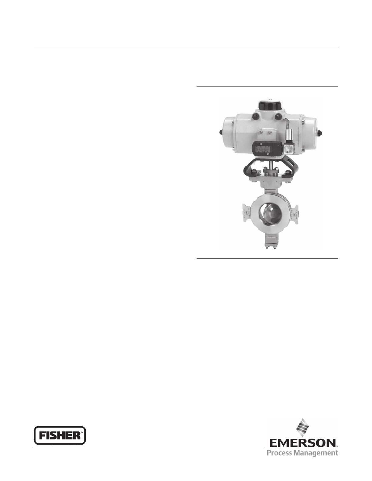
Figure 1. Fisher A81 Valve with FieldQ™ Actuator
W9479
Introduction
Scope of Manual
This instruction manual includes installation, maintenance, and parts information for the Fisher POSI‐SEAL A81 valve,
DN50 through DN300 or NPS 2 through NPS 12 (figure 1). Refer to separate instruction manuals for information
covering the power on‐off actuator and accessories.
Do not install, operate, or maintain an A81 valve without being fully trained and qualified in valve, actuator, and
accessory installation, operation, and maintenance. To avoid personal injury or property damage, it is important to
carefully read, understand, and follow all the contents of this manual, including all safety cautions and warnings. If you
have any questions about these instructions, contact your Emerson Process Management sales office before
proceeding.
www.Fisher.com
Page 2
A81 Valve
May 2011
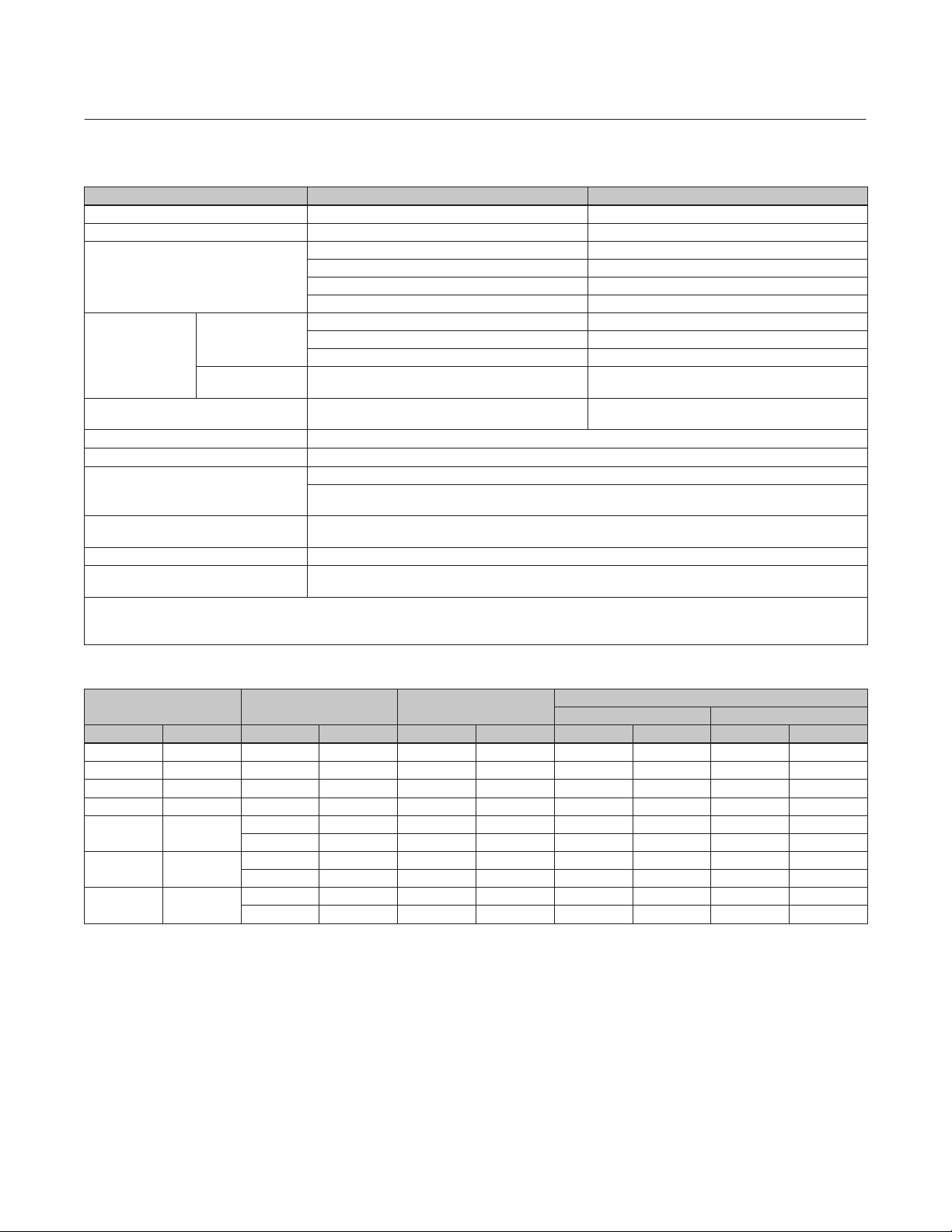
Table 1. Fisher A81 Valve Specifications
Specifications EN ASME
Valve Body Size DN 50, 80, 100, 150, 200, 250, and 300 NPS 2, 3, 4, 6, 8, 10, and 12
Pressure Rating PN 10 to 40 per EN 12516‐1 CL150 and 300 per ASME B16.34
EN 1.0619 steel WCC steel
Valve Body Materials
PTFE or RPTFE
(3)
Disk Materials
End Connections
Valve Body Style Wafer (flangeless) and single flange with tapped or through holes
Face‐to‐Face Dimensions Meets MSS SP68, API 609, and EN 558 standards
Shutoff
Flow Direction
Flow Characteristic Approximately linear
Disk Rotation
1. This material is not listed in EN 12516-1 or ASME B16.34. See table 4 for pressure/temperature ratings.
2. UHMWPE stands for ultra high molecular weight polyethylene.
3. RPTFE is a reinforced PTFE seal.
4. This material is not listed in EN 12516-1. See table 4 for pressure/temperature ratings.
Seal
Metal or
UHMWPE
(2)
Seal
Standard (forward flow) is with the seal retainer facing upstream; reverse flow is permissible within specified
Counterclockwise to open (when viewed from actuator side of valve body) through 90 degrees of disk
EN 1.4409 stainless steel CF3M (316L) stainless steel
EN 1.4409 stainless steel CF3M stainless steel
Chrome‐plated EN 1.4409 Stainless Steel Chrome‐plated CF3M Stainless Steel
Mates with raised‐face flanges
per EN 1092‐1
(1)
CW2M
(4)
M35‐2
CW2M CW2M
M35‐2 M35‐2
PTFE, RPTFE, or UHMWPE seal ring ‐ No visible leakage per MSS SP‐61
S31600 (316 SST) seal ring - 0.1 scfh per unit of NPS (NPS 6 valve = 0.6 scfh)
per MSS SP-61
pressure drop limitations
rotation
Instruction Manual
D103302X012
(1)
CW2M
M35‐2
Mates with raised‐face flanges
per ASME B16.5
Table 2. Valve Size, Shaft Diameter, and Approximate Weight
VALVE SIZE PRESSURE RATING SHAFT DIAMETER
DN NPS EN ASME mm Inches kg Pounds kg Pounds
50 2 PN10‐40 CL150/300 12.7 1/2 4.7 10 6.7 15
80 3 PN10‐40 CL150/300 15.9 5/8 7.5 17 11.2 25
100 4 PN10‐40 CL150/300 19.1 3/4 12.5 28 17.6 39
150 6 PN10‐40 CL150/300 25.4 1 15.7 35 26.5 58
200 8
250 10
300 12
PN10‐16 CL150 31.8 1‐1/4 30.2 67 40.2 89
PN25‐40 CL300 31.8 1‐1/4 33.9 75 46.0 102
PN10‐16 CL150 31.8 1‐1/4 38.9 86 50.5 111
PN25‐40 CL300 31.8 1‐1/4 51.8 114 79.2 175
PN10‐16 CL150 38.1 1‐1/2 68.7 151 98.3 217
PN25‐40 CL300 38.1 1‐1/2 76.6 169 104.6 231
Wafer‐Style Single‐Flange
APPROXIMATE WEIGHT
Description
The A81 rotary valve with FieldQ rack‐and‐pinion actuator offers automated on‐off, quarter‐turn performance. FieldQ
is available in spring‐return and double‐acting piston designs.
The valve body meets PN 10 through PN 40, CL150, and CL300 ratings. Face‐to‐face dimensions meet EN 558, API
609, and MSS‐SP68 standards. Retainer clips provide for versatility to mount and align the same wafer style valve body
in different piping configurations (ASME and EN ratings).
2
Page 3
Instruction Manual
D103302X012
A81 Valve
May 2011
The A81 rotary valve features an eccentrically‐mounted disk with either soft or metal seal, providing capability for
enhanced shutoff. The interchangeable sealing technology allows for the same valve body to accept both soft and
metal seals.
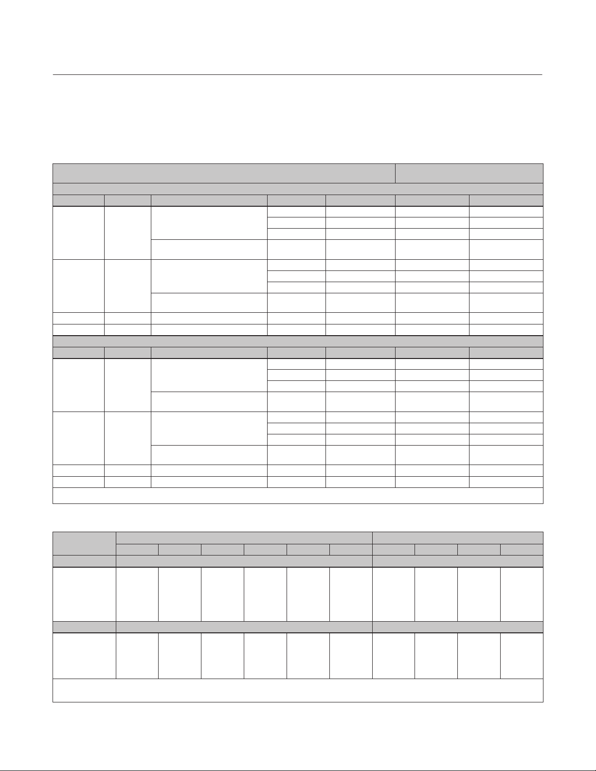
Table 3. Material Temperature Capabilities
MATERIAL TEMPERATURE
EN Materials
Valve Body Shaft Bearing Lining and Jacket Seal Packing _C _F
1.0619 Steel S17400 or
S20910
PEEK / PTFE
PTFE or RPTFE PTFE or Graphite –10 to 232 14 to 450
UHMWPE PTFE or Graphite –10 to 93 14 to 200
Metal PTFE or Graphite –10 to 232 14 to 450
R30006 (Alloy 6) or S31600
Metal Graphite –10 to 400
(2)
Nitride
1.4409
Stainless
Steel
S20910 PEEK / PTFE
R30006 (Alloy 6) or S31600
PTFE or RPTFE PTFE or Graphite –10 to 232 14 to 450
UHMWPE PTFE or Graphite –10 to 93 14 to 200
Metal PTFE or Graphite –10 to 232 14 to 450
Metal Graphite –10 to 500
(2)
Nitride
CW2M N10276 PEEK / PTFE PTFE or RPTFE PTFE –10 to 232 14 to 450
M35‐2 N05500 PEEK / PTFE PTFE or RPTFE PTFE –10 to 232 14 to 450
ASME Materials
Valve Body Shaft Bearing Lining and Jacket Seal Packing _C _F
WCC steel S17400 or
S20910
PEEK / PTFE
PTFE or RPTFE PTFE or Graphite –29 to 232 -20 to 450
UHMWPE PTFE or Graphite –18 to 93 0 to 200
Metal PTFE or Graphite –29 to 232 -20 to 450
R30006 (Alloy 6) or S31600
Metal Graphite –29 to 427
(2)
Nitride
CF3M
Stainless
Steel
S20910 PEEK / PTFE
R30006 (Alloy 6) or S31600
PTFE or RPTFE PTFE or Graphite –46 to 232 –50 to 450
UHMWPE PTFE or Graphite –18 to 93 0 to 200
Metal PTFE or Graphite –46 to 232 –50 to 450
Metal Graphite –46 to 454
(2)
Nitride
CW2M N10276 PEEK / PTFE PTFE or RPTFE PTFE –46 to 232 –50 to 450
M35‐2 N05500 PEEK / PTFE PTFE or RPTFE PTFE –46 to 232 –50 to 450
1. Minimum allowable temperature for PN series flanges is -10_C (14_F). See requirements of EN 13445‐2 Annex B for applications below -10_C (14_F) with PN series flanges.
2. For applications exceeding 316_C (600_F), consult your Emerson Process Management sales office for appropriate disk material selection.
LIMITS
(1)
14 to 752
14 to 932
-20 to 800
–50 to 850
(2)
(2)
(2)
(2)
Table 4. Maximum Allowable Inlet Pressure for CW2M and M35‐2 Valves
(1)
TEMPERATURE
150
(2)
300
(2)
PN 10
CW2M
(2)
PN 16
(2)
PN 25
(2)
PN 40
(2)
PN 10
(2)
PN 16
_C Bar Bar
–46 to 38
50
100
150
200
232
20.0
19.5
17.7
15.8
13.8
12.7
51.7
51.7
51.5
50.3
48.3
47.0
10.0
9.9
9.4
9.4
9.1
9.1
16.0
15.9
15.1
15.1
14.6
14.6
25.0
24.8
23.6
23.6
22.9
22.9
40.0
39.6
37.8
37.8
36.6
36.6
9.3
9.3
9.3
9.3
9.0
9.0
15.2
15.2
15.1
14.8
14.5
14.5
_F Psig Psig
–50 to 100
200
300
400
450
1. This material is not listed in EN 12516‐1 or ASME B16.34. Also see the Installation section.
2. The designations PN or 150 and 300 are used only to indicate relative pressure‐retaining capabilities and are not EN or ASME pressure‐temperature rating class designations.
3. This material is not listed in EN 12516-1. Also see the Installation section.
290
260
230
200
185
750
750
730
700
680
145
144
137
133
133
232
230
219
212
212
362
359
342
331
331
580
575
548
530
530
135
135
135
130
130
220
220
215
210
210
M35‐2
(2)
(3)
PN 25
23.8
23.8
23.7
23.4
22.5
22.4
345
345
340
325
325
(2)
PN 40
(2)
37.9
37.9
37.8
37.2
36.3
36.2
550
540
525
525
525
3
Page 4

A81 Valve
May 2011
Instruction Manual
D103302X012
Installation
Key numbers in this procedure are shown in figure 9 unless otherwise indicated.
WARNING
Always wear protective gloves, clothing and eyewear when performing any installation operations to avoid personal injury.
To avoid personal injury or property damage resulting from the bursting of pressure retaining parts, be certain the service
conditions do not exceed either the valve body rating or the flange joint rating, or other limits given in table 1 or on the
nameplate. Use pressure‐relieving or pressure‐limiting devices to prevent the service conditions from exceeding these
limits.
If installing into an existing application, also refer to the WARNING at the beginning of the Maintenance section on page 8
in this manual.
CAUTION
The valve configuration and construction materials were selected to meet particular pressure, temperature, pressure drop,
and controlled fluid conditions specified in the customer's order. Because some valve body/trim material combinations are
limited in their pressure drop and temperature range capabilities, do not apply any other conditions to the valve without
first contacting your Emerson Process Management sales office.
The maximum allowable inlet pressures for steel and stainless steel valve bodies are consistent with the
pressure‐temperature ratings shown in table 1, except where further limited by the trim and packing material
temperature capabilities given in table 3. Valves are also available in CW2M and M35‐2 valve body materials. The
CW2M valve body material is not listed in EN 12516-1 or in ASME B16.34. The M35-2 valve body material is listed in
ASME B16.34, but is not listed in EN 12516-1. Valve bodies constructed of these materials mate with EN and ASME
flanges, but must not be installed in systems requiring conformance to EN or ASME standards if not included in EN or
ASME pressure/temperature ratings. Maximum allowable inlet pressures for A81 valve bodies made of CW2M or
M35‐2 construction materials are shown in table 4.
1. Install a three‐valve bypass around the control valve assembly if continuous operation is necessary during
inspection and maintenance of the valve body.
2. Inspect the valve body to be certain it is free of foreign material.
3. The valve is normally shipped as part of a control valve assembly, with an actuator mounted on the valve body.
If the valve body and actuator have been purchased separately or if the actuator has been removed for maintenance,
mount the actuator, and adjust actuator travel before inserting the valve body into the line. This is necessary due to
the measurements that must be made during the actuator adjustment process. Refer to the Actuator Mounting
section on page 18 of this manual and to the separate actuator instruction manual for mounting and adjusting
instructions before proceeding.
4. Inspect adjacent pipelines to be certain they are free of any foreign material, such as pipe scale or welding slag, that
could damage the valve body seating surfaces.
CAUTION
Damage to the disk (key 3) will occur if any pipe flanges or piping connected to the valve body interfere with the disk
rotation path. However, the disk can be rotated without interference when the valve body is installed between adjacent
pipe flanges or piping that has an inside diameter equal to or greater than either schedule 80 pipe or compatible EN pipe
4
Page 5

Instruction Manual
D103302X012
sizes. If piping with a smaller inner diameter than specified above is connected to the valve, measure carefully to be certain
the disk rotates without interference before putting the valve into operation.
A81 Valve
May 2011
5. Flow is in the standard direction when the seal retainer (key 2) is facing upstream. Standard flow direction is also
indicated by the flow direction arrow cast into the valve body. Flow in the reverse direction is permissible within
allowable pressure drop limits.
CAUTION
A81 disk rotation is counterclockwise to open (when viewed from the actuator side of the valve body, see figure 7) through
90 degrees of disk rotation. Rotating the disk (key 3) past either the open or closed position could damage the seal and disk
sealing surfaces and could cause the disk to jam in the seal retainer.
6. With the disk in the closed position, install line flange gaskets, and insert the valve between the pipeline flanges.
Use either flat sheet gaskets or spiral‐wound gaskets with compression‐controlling centering rings. Spiral‐wound
gaskets without compression‐controlling centering rings are not recommended for this purpose.
7. Depending on valve size and pressure rating, the wafer style valve is centered in the pipeline using either retainer
clips or the flange bolt holes. (For valves that have four flange bolt holes in the valve body (key 1), each hole
engages one corresponding line flange stud.) Insert the valve between the flanges and use either the retainer clips
or install two or more line flange studs into the line flanges to help hold the valve in position while centering the
valve. Carefully center the valve on the flanges to ensure disk clearance.
D Select and install two pipeline gaskets.
Note
Lubricate line flange studs before inserting them into flanges. If necessary, provide additional support for the control valve
assembly because of its combined weight.
WARNING
For single flange valve bodies with threaded line bolt holes, personal injury and property damage could result from sudden
release of process pressure if line bolts are not properly installed. To ensure proper line bolt thread engagement, line studs
must be centered in the threaded section of the valve body so that each stud has equal thread engagement in the body. See
figure 2.
8. After centering the valve body, first lubricate and then install the remaining line flange bolting to secure the valve in
the pipeline. Tighten the nuts to the line flange studs in a crisscross pattern to ensure proper alignment of valve,
gaskets, and flanges.
5
Page 6
A81 Valve
May 2011
Instruction Manual
D103302X012
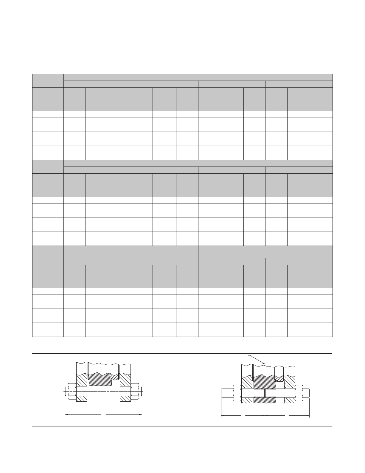
Table 5. Stud Bolt Data
VALVE SIZE
DN
50 4 M16X2 125 4 M16X2 125 4 M16X2 130 4 M16X2 130
80 8 M16X2 140 8 M16X2 140 8 M16X2 150 8 M16X2 150
100 8 M16X2 150 8 M16X2 150 8 M20X2.5 160 8 M20X2.5 160
150 8 M20X2.5 160 8 M20X2.5 160 8 M24X3 180 8 M24X3 180
200 8 M20X2.5 170 12 M20X2.5 170 12 M24X3 190 12 M27X3 210
250 12 M20X2.5 180 12 M24X3 190 12 M27X3 210 12 M30X3.5 230
300 12 M20X2.5 190 12 M24X3 200 16 M27X3 230 16 M30X3.5 250
VALVE SIZE
DN
50 - - - - - - - - - - - - - - - - - - - - - - - - - - - - - - - - - - - -
80 16 M16X2 85 16 M16X2 85 16 M16X2 90 16 M16X2 90
100 16 M16X2 90 16 M16X2 90 16 M20X2.5 100 16 M20X2.5 100
150 16 M20X2.5 110 16 M20X2.5 110 - - - - - - - - - - - - - - - - - -
200 16 M20X2.5 110 24 M20X2.5 110 24 M24X3 120 - - - - - - - - -
250 24 M20X2.5 120 24 M24X3 120 24 M27X3 130 - - - - - - - - -
300 24 M20X2.5 120 24 M24X3 130 24 M27X3 140 24 M30X3.5 150
VALVE SIZE
NPS
2 4 5/8‐11 5 8 5/8‐11 5.25 - - - - - - - - - - - - - - - - - -
3 4 5/8‐11 5.75 8 3/4‐10 6.5 8 5/8‐11 4.00 16 3/4‐10 4.25
4 8 5/8‐11 6 8 3/4‐10 7 16 5/8‐11 4.00 16 3/4‐10 4.50
6 8 3/4‐10 6.5 12 3/4‐10 7.5 16 3/4‐10 4.25 24 3/4‐10 4.75
8 8 3/4‐10 7 12 7/8‐9 9 16 3/4‐10 4.50 24 7/8‐9 5.50
10 12 7/8‐9 8 16 1‐8 10 24 7/8‐9 5.00 32 1‐8 6.50
12 12 7/8‐9 8.5 16 1‐1/8‐8 11 24 7/8‐9 5.25 32 1‐1/8‐8 7.00
No. of
Stud
Bolts
No. of
Stud
Bolts
WAFER STYLE AND SINGLE FLANGE STYLE WITH THROUGH
No. of
Stud
Bolts
PN 10 PN 16 PN 25 PN 40
Size Dia
&
Thread,
mm
PN 10 PN 16 PN 25 PN 40
Size Dia
&
Thread,
mm
CL150 CL300 CL150 CL300
Size Dia
&
Thread,
Inch
WAFER STYLE AND SINGLE FLANGE STYLE WITH THROUGH DRILLED HOLES
A
Dimen‐
sion,
mm
Dimen‐
sion,
mm
DRILLED HOLES
Dimen‐
sion,
Inch
No. of
B
No. of
A
No. of
Stud
Bolts
Stud
Bolts
Stud
Bolts
Size Dia
&
Thread,
mm
SINGLE FLANGE STYLE (THREADED HOLES)
Size Dia
&
Thread,
mm
Size Dia
&
Thread,
Inch
A
Dimen‐
sion,
mm
B
Dimen‐
sion,
mm
A
Dimen‐
sion,
Inch
No. of
Stud
Bolts
No. of
Stud
Bolts
No. of
Stud
Bolts
Size Dia
&
Thread,
mm
Size Dia
&
Thread,
mm
SINGLE FLANGE STYLE (THREADED HOLES)
Size Dia
&
Thread,
Inch
A
Dimen‐
sion,
mm
B
Dimen‐
sion,
mm
B
Dimen‐
sion,
Inch
No. of
Stud
Bolts
No. of
Stud
Bolts
No. of
Stud
Bolts
Size Dia
&
Thread,
mm
Size Dia
&
Thread,
mm
Size Dia
&
Thread,
Inch
A
Dimen‐
sion,
mm
B
Dimen‐
sion,
mm
B
Dimen‐
sion,
Inch
Figure 2. Stud Bolts for Installation (also see table 5)
A3887-1
WAFER‐STYLE VALVE BODY SINGLE FLANGE‐STYLE VALVE BODY (THREADED HOLES)
6
A
CENTERLINE OF
THREADED SECTION
A3886-1
B
B
Page 7
Instruction Manual
D103302X012
A81 Valve
May 2011
WARNING
An A81 valve body is not necessarily grounded when installed in a pipeline. If the valve is used in a flammable or hazardous
atmosphere or for oxygen service, an explosion could result due to a discharge of static electricity from the valve
components. To avoid personal injury or property damage, always make sure the valve body is grounded to the pipeline
before putting the control valve assembly into operation in a flammable or hazardous atmosphere.
Note
Standard packings for the A81 valve are composed of all conductive packing rings (graphite ribbon packing) or partially conductive
packing rings (such as a carbon‐filled PTFE female adaptor with PTFE V‐ring packing) to electrically bond the shaft to the valve
body for hazardous area service. For oxygen service applications, provide alternate shaft‐to‐valve body bonding according to the
following step.
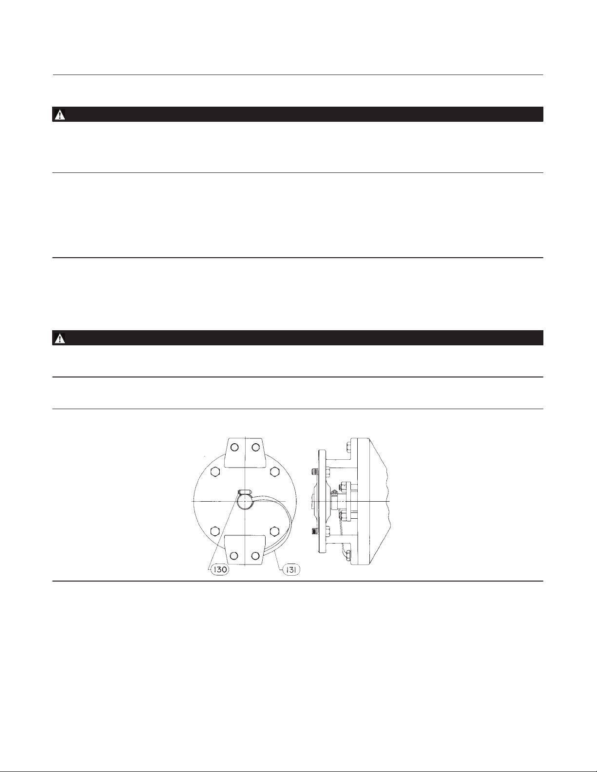
9. For oxygen service applications, attach the bonding strap assembly (key 131, figure 3) to the shaft with the clamp
(key 130, figure 3), and connect the other end of the bonding strap assembly to the valve body with the cap screw
(key 35). Secure each cap screw with a hex nut (key 36).
WARNING
Personal injury could result from packing leakage. Valve packing was tightened prior to shipment; however, the packing
might require some readjustment to meet specific service conditions.
Figure 3. Optional Shaft‐to‐Valve Body Bonding Strap Assembly
7
Page 8
A81 Valve
May 2011
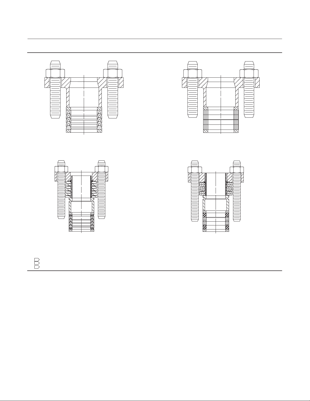
Figure 4. Packing Arrangement Details
Instruction Manual
D103302X012
GE39901‐A
PTFE V‐RING
GE39986‐A
GRAPHITE RIBBON
STANDARD PACKING
GE40113‐A
SINGLE PTFE PACKING
GE40118‐A
GRAPHITE PACKING
ENVIRO‐SEAL PACKING
NOTES:
1
WITH CONDUCTIVE PACKING, THE FEMALE ADAPTOR IN PTFE V‐RING PACKING IS CARBON‐FILLED PTFE.
2
APPLY LUBRICANT.
3
THESE TWO SURFACES SHOULD REMAIN PARALLEL AS YOU ALTERNATELY AND EVENLY TIGHTEN THE PACKING NUTS (KEY 28).
Valves with ENVIRO‐SEALt packing systems will not require this initial re‐adjustment. See ENVIRO‐SEAL Packing
System for Rotary Valves Instruction Manual (D101643X012) for packing instructions. If you wish to convert your
present packing arrangement to ENVIRO‐SEAL packing, refer to the retrofit kits listed in the parts kit sub‐section on
page 19 of this manual.
Maintenance
Valve body parts are subject to normal wear and must be inspected regularly and replaced as necessary. The frequency
of inspection and replacement depends upon the severity of service conditions. Instructions are given in this section
for: replacing trim components, changing disk rotation or valve action, and mounting and adjusting the actuator.
As used in these instructions, actuator refers to power actuators (such as pneumatic diaphragm, piston actuators, and
rack and pinion actuators).
8
Page 9

Instruction Manual
D103302X012
A81 Valve
May 2011
WARNING
Avoid personal injury and property damage from sudden release of process pressure or bursting of parts. Before performing
any maintenance operations:
D Do not remove the actuator from the valve while the valve is still pressurized.
D Always wear protective gloves, clothing, and eyewear when performing any maintenance operations.
D Disconnect any operating lines providing air pressure, electric power, or a control signal to the actuator. Be sure the
actuator cannot suddenly open or close the valve.
D Use bypass valves or completely shut off the process to isolate the valve from process pressure. Relieve process pressure
on both sides of the valve. Drain the process media from both sides of the valve.
D Vent the power actuator loading pressure and relieve any spring precompression.
D Use lock‐out procedures to be sure the above measures stay in effect while you work on the equipment.
D The valve packing box may contain process fluids that are pressurized, even when the valve has been removed from the
pipeline. Process fluids may spray out when removing the packing hardware or packing rings, or when loosening the
packing box pipe plug.
D Check with your process or safety engineer for any additional measures that must be taken to protect against process
media.
Packing Maintenance
Refer to figure 4 for available packing configurations. All maintenance operations in this section may be performed
with the valve in the line. Packing may be PTFE V‐ring or graphite.
An ENVIRO‐SEAL packing system is also available with the A81 valve. To install the ENVIRO‐SEAL packing system in an
existing valve, follow the instructions in the instruction manual included with the packing system (D101643X012). To
remove packing parts in a valve with the ENVIRO‐SEAL packing system, follow the procedures for valves with the
ENVIRO‐SEAL packing system in this section. Install the replacement packing following the instructions in the packing
system instruction manual (D101643X012).
Stopping Leakage
For valves with PTFE or graphite packing:
CAUTION
Tighten the packing flange only enough to prevent shaft leakage. Excessive tightening will only accelerate wear of the
packing and could produce higher torques on the valve.
Leakage around the packing followers can be stopped by tightening the packing flange nuts (key 28, figure 9).
If the packing is relatively new and tight on the shaft, and if tightening the packing flange nuts does not stop leakage,
the shaft may be worn or nicked so that a seal cannot be made. If the leakage comes from the outside diameter of the
packing, the leakage may be caused by nicks or scratches around the packing box wall. Inspect the shaft and packing
box wall for nicks and scratches when performing the packing replacement procedures.
9
Page 10

A81 Valve
May 2011
Instruction Manual
D103302X012
For valves with the ENVIRO‐SEAL packing system:
Optimum performance of the ENVIRO‐SEAL packing system is obtained when the Belleville springs are tightened to
their “target load.” The target load is the point where the springs are compressed to 85% of their maximum deflection,
or nearly flat. Maximum deflection is when the springs are 100% compressed, or completely flat.
Under normal conditions, the packing nuts should not require re‐tightening. However, when servicing, if the springs
do not remain at the target load of 85% compression, retighten the packing box nuts according to the following
procedure:
1. Tighten the packing flange nuts alternately and evenly, keeping the packing flange parallel with the valve flange
(see figure 4), until the Belleville springs are compressed 100% (or completely flat).
D For PTFE packing, loosen each packing flange nut one half turn (180_ of rotation).
D For Graphite packing, loosen each packing flange nut one quarter turn (90_ of rotation).
The target load of 85% compression has now been reached. If leakage continues, replace the packing components as
described in the following procedures.
Replacing the Packing
To replace the packing, the actuator must be removed. Also, the valve should be removed from the pipeline to allow
proper readjustment of the disk position.
WARNING
The edges of a rotating disk have a shearing effect that may result in personal injury. To help prevent such injury, stay clear
of the disk edges when rotating the disk (key 3).
CAUTION
Damage to the disk (key 3) may occur if the disk is not closed when the valve is being removed from the pipeline. If
necessary, apply operating pressure to the actuator temporarily to retain the disk in the closed position while removing the
valve from the pipeline.
For valves with PTFE or graphite packing:
Key numbers in this procedure are shown in figure 9 unless otherwise indicated.
1. Isolate the control valve from the line pressure, release pressure from both sides of the valve body, and drain the
process media from both sides of the valve. If using a power actuator, also shutoff all pressure lines to the power
actuator, release all pressure from the actuator. Use lock‐out procedures to be sure the above measures stay in
effect while you work on the equipment.
CAUTION
When removing the actuator in the following step, use a wheel puller to separate the actuator parts from the valve shaft.
Do not drive the actuator parts off the valve shaft because this could damage valve trim components.
10
Page 11

Instruction Manual
D103302X012
A81 Valve
May 2011
2. Remove the actuator per instructions in separate actuator instruction manuals, then remove the cap screws and
nuts (keys 35 and 36). Remove the clamp (key 130, figure 3) if the strap (key 131, figure 3) is used.
3. Remove the packing flange nuts and the packing flange (key 26) if used and pull out the packing follower (key 25).
4. Remove the anti‐blowout ring (key 40) from the drive shaft (key 10).
5. Remove the old packing rings (key 24) and, if used, the packing washers (key 31). Carefully avoid scratching the
shaft or packing box wall to avoid damage that could cause leakage around the shaft. Clean all accessible metal
parts and surfaces to remove particles that would prevent the packing from sealing.
WARNING
Do not lubricate parts when used in oxygen service, or where the lubrication is incompatible with the process media. Any
use of lubricant can lead to the sudden explosion of media due to the oil/oxygen mixture, causing personal injury or
property damage.
6. Use the appropriate procedures below for installing packing.
D Install the packing as shown in figure 4.
D With graphite ribbon packing, stack the packing rings and packing washers together, and slide the stack into the
packing box as far as it will go while carefully avoiding trapping air between the rings.
D Install the anti‐blowout ring (key 40) in the groove on the drive shaft (key 10).
D Install the packing follower and, if used, the packing flange.
D Install the packing flange nuts, and tighten them only far enough to stop leakage under normal operating
conditions.
D For oxygen service applications, attach the bonding strap assembly (key 131, figure 3) to the shaft with the clamp
(key 130, figure 3), and connect the other end of the bonding strap assembly to the valve body with a cap screw
(key 35). Secure each cap screw with a hex nut (key 36).
7. Mount the actuator and adjust the closed position of the valve, per the Actuator Mounting section on page 18 of
this manual, before returning the valve to service.
8. When placing the control valve into operation, check around the packing follower for leakage; retighten the
packing flange nuts as required according to accepted bolting procedures.
For valves with ENVIRO‐SEAL packing systems:
1. Isolate the control valve from the line pressure, release pressure from both sides of the valve body, and drain the
process media from both sides of the valve. If using a power actuator, also shutoff all pressure lines to the power
actuator, release all pressure from the actuator. Use lock‐out procedures to be sure that the above measures stay in
effect while you work on the equipment.
CAUTION
When removing the actuator, use a wheel puller to separate the actuator parts from the valve shaft. Do not drive the
actuator parts off the valve shaft because this could damage valve trim components.
2. Remove the actuator per instructions in separate actuator instruction manuals, then remove the cap screws and
nuts (keys 35 and 36). Remove the clamp (key 130, figure 3) if the strap (key 131, figure 3) is used.
11
Page 12

A81 Valve
May 2011
Figure 5. Orientation of Bearing Tabs
Instruction Manual
D103302X012
BACKSIDE OF VALVE
BEARING TAB
BEARING TAB
3. Loosen the two packing hex nuts evenly to remove spring tension, then remove the nuts.
4. Remove the packing flange and spring pack assembly. The spring pack assembly consists of the spring stack and
packing follower. The spring stack is retained on the packing follower by an O‐ring. Remove the anti‐blowout ring
(key 40) from the driveshaft (key 10). Remove the anti‐extrusion washer, the packing set, and the packing ring.
CAUTION
The valve shaft surface condition is critical in making and maintaining a good seal. If the valve shaft surface is scratched,
nicked, dented, or worn, replace the valve shaft before replacing the packing system.
5. Inspect the existing valve shaft. If necessary, replace the valve shaft as described in the Replacing the Disk, Shafts,
or Bearings section.
6. Install the new packing system components as described in the ENVIRO‐SEAL Packing System for Rotary Valves
Instruction Manual (D101643X012).
7. Install the anti‐blowout ring (key 40) onto the drive shaft (key 10) before installing the packing follower.
8. Mount the actuator and adjust the closed position of the valve, per the Actuator Mounting section on page 18 of
this manual, before returning the valve to service.
Replacing the Seal Ring Assembly
Perform this procedure only if the control valve is not shutting off properly (that is, leaking downstream). This
procedure does not require removing the actuator from the valve body.
12
Page 13

Instruction Manual
D103302X012
A81 Valve
May 2011
Key numbers in this procedure are shown in figure 9 unless otherwise indicated.
1. Isolate the control valve from line pressure, and relieve pressure from the valve body. Shut off and disconnect all
lines from the power actuator.
WARNING
The edges of a rotating disk have a shearing effect that may result in personal injury. To help prevent such injury, stay clear
of the disk edges when rotating the disk (key 3).
CAUTION
Damage to the disk (key 3) may occur if the disk is not closed when the valve is being removed from the pipeline. If
necessary, apply operating pressure to the actuator temporarily to retain the disk in the closed position while removing the
valve from the pipeline.
2. Unscrew the flange bolts, and remove the valve from the pipeline.
3. Unscrew the machine screws (key 14), remove the retainer clip (key 13), and remove the seal retainer (key 2).
4. Remove the seal ring assembly (key 4).
5. The valve must be closed during seal ring installation to permit accurate centering of the seal. To install the new
seal ring assembly:
D For a soft seal, if the spring (key 5) was disassembled, hook the spring ends together. Work the spring into the
recess in the seal ring (key 4). Place the seal ring assembly onto the disk. Set the retainer onto the seal, making sure
proper alignment between the seal and retainer has been achieved.
D For the metal seal ring assembly, place the seal ring assembly onto the disk. Set the retainer onto the seal, making
sure proper alignment between the seal and retainer has been achieved.
6. Attach the seal retainer (key 2) and the retainer clips (key 13) to the valve body and secure with the machine screws
(key 14).
7. Be certain the disk is closed before installing the valve according to the Installation section on page 4 of this
manual.
Replacing the Disk, Shafts, or Bearings
Key numbers in this procedure are shown in figure 9 unless otherwise indicated.
Table 6. Follower Shaft Internal Threads
VALVE SIZE
DN NPS
50 2 M8 X 1.25
80 3 M10 X 1.50
100 4 M12 X 1.75
180 6 M16 X 2.00
200 8 M20 X 2.50
250 10 M20 X 2.50
300 12 M24 X 3.00
THREAD SIZE
13
Page 14

A81 Valve
May 2011
Instruction Manual
D103302X012
1. Isolate the control valve from the line pressure, release pressure from both sides of the valve body, and drain the
process media from both sides of the valve. If using a power actuator, also shutoff all pressure lines to the power
actuator, release all pressure from the actuator. Use lock‐out procedures to be sure that the above measures stay in
effect while you work on the equipment.
CAUTION
When removing the actuator in the following step, use a wheel puller to separate the actuator parts from the valve shaft.
Do not drive the actuator parts off the valve shaft because this could damage valve trim components.
2. Remove the actuator per instructions in separate actuator instruction manuals, then remove the cap screws and
nuts (keys 35 and 36). Remove the clamp (key 130, figure 3) if the strap (key 131, figure 3) is used.
3. Remove the packing flange nuts and the packing flange (key 26) if used and pull out the packing follower (key 25).
Table 7. Recommended Blind Flange Bolt Torque
VALVE SIZE TORQUE
DN NPS NSm lbfSft
50 to 150 2 to 6 9.5 7.0
200, 250 8, 10 23 17
300 12 45 33
Disassembly
1. Remove the seal ring assembly according to steps 3 and 4 of the Replacing Seal Ring section on page 12 of this
manual.
2. Remove hex nuts, blind flange, gasket, spacer (if present), follower spring seats, and follower spring (keys 19, 17,
16, 15, 9, and 12).
3. Clean the gasket surfaces on the blind flange (key 17) and on the end of the valve body (key 1).
4. Rotate the disk (key 3) to the fully open position.
5. Refer to figure 6 and determine the location of the smaller end of the taper pins (key 8). Drive out the taper pins
and expansion pins (key 7) towards the larger end.
WARNING
Once the shafts have been removed in the following step, the disk may fall from the valve body. To avoid personal injury and
disk damage, support the disk to prevent it from falling as the shafts are being removed.
6. Pull the follower shaft (key 11) out through the outboard end of the valve body. If the follower shaft cannot be
pulled free, the end of the follower shaft is internally threaded (see table 6) for screwing in a bolt or stud to aid in
pulling the follower shaft.
7. Pull the drive shaft (key 10) out through the actuator end of the valve body and remove the anti‐blowout ring (key
40) from the drive shaft.
8. Remove the disk (key 3) from the valve body.
9. Remove the packing (key 24, figure 4) and the packing box ring (key 23, figure 4).
10. If either of the bearings (key 6) require replacement, remove them.
11. Clean the packing box and [metal packing box parts].
14
Page 15

Instruction Manual
D103302X012
Assembly
WARNING
A81 Valve
May 2011
Do not lubricate bearings that will be used for oxygen service, or where the lubrication is incompatible with the process
media. Any
use of lubricant can lead to the sudden explosion of media due to the oil/oxygen mixture, causing personal
injury or property damage.
CAUTION
To avoid possible product damage, ensure the bearing tabs are oriented correctly when installing in the following
procedure. See figure 5 for proper orientation of the bearings.
Figure 6. Taper / Expansion Pin Installation
“T” STAMPED ON ACTUATOR
END OF DISK
1
TAPER/EXPANSION PIN LOCATION
W9487
1
INSTALL THE PINS FROM THIS SIDE OF THE DISK.
15
Page 16

A81 Valve
May 2011
Figure 7. Sectional of Typical Valve Body
X2
CCW DISK ROTATION TO OPEN
X1
Instruction Manual
D103302X012
ACTUATOR END OF SHAFT
POSITION INDICATION MARK INDICATES
APPROXIMATE DISK POSITION
Figure 8. Follower Spring/Spring Seat Assembly
FOLLOWER SPRING SEAT
(KEY 9)
16
FOLLOWER SPRING
(KEY 12)
FOLLOWER SPRING SEAT
(KEY 9)
Page 17

Instruction Manual
D103302X012
A81 Valve
May 2011
1. If new bearings (key 6) are required, install and orient them in the valve body, as shown in figure 5. Ensure the
bearings are fully seated, contacting the inside diameter of the valve body.
2. Insert the disk into the valve body as shown in figure 6, ensuring the “T” stamped on the disk hub is oriented toward
the actuator end of the valve body.
3. Install the drive shaft (key 10) through the valve body into the disk. The disk/shaft connection utilizes taper and
expansion pins. The hole for the drive shaft connection is slightly off‐center to prevent the drive shaft from being
installed in the wrong orientation. Orient the position indication mark on the end of the shaft with the face of the
disk as shown in figure 7. The hole for the follower shaft connection is on‐center. Insert the expansion pins into the
disk until they are seated, as shown in figure 6. Once in place, insert the taper pins. The taper pins must be driven
into the disk/shaft/expansion pin assemblies until “solid contact” is felt. “Solid contact” can be identified by the
sound of the hammer blow and the bounce felt in the hammer.
4. Reinstall the follower spring/spring seat assembly (keys 9, 12, and 9, figure 8) inside the follower shaft.
5. Install the spacer (key 15) if used, and the gasket, blind flange, and hex nuts (keys 16, 17, and 19). Ensure the blind
flange is oriented so the serrations face the gasket and valve body. Tighten the hex nuts (key 19) per table 7.
6. The valve must be closed during seal ring installation to permit accurate centering of the seal. To install the new
seal ring assembly or flow ring:
Table 8. Recommended Actuator‐Mounting Bolt Torque
VALVE SIZE TORQUE
DN NPS NSm lbfSft.
50, 80, 100, and 150 2, 3, 4, and 6 120 88
200, 250, and 300 8, 10, and 12 250 185
D For a soft seal, if the spring (key 5) was disassembled, hook the spring ends together. Work the spring into the
recess in the seal ring (key 4). Place the seal ring assembly onto the disk. Set the retainer onto the seal, making sure
proper alignment between the seal and retainer has been achieved.
D For the metal seal ring assembly, place the seal ring assembly onto the disk. Set the retainer onto the seal.
D For the flow ring construction, place the gasket (key 41) onto the valve body. Set the retainer onto the gasket.
7. Attach the seal retainer (key 2) and the retainer clips (key 13) to the valve body and secure with the machine screws
(key 14).
8. Insert a packing box ring (key 23) into the packing box.
9. For standard packing, install the packing according to the appropriate instructions presented in step 5 of the
Replacing Packing section on page 11 of this manual. For ENVIRO‐SEAL packing, install the new packing system
components as described in the ENVIRO‐SEAL Packing System for Rotary Valves Instruction Manual
(D101643X012).
10. Install the anti‐blowout ring (key 40) in the groove in the drive shaft.
11. Rotate the disk to the approximate closed position.
12. Mount and adjust the actuator per the following Actuator Mounting section on page 18 of this manual.
17
Page 18

A81 Valve
May 2011
Instruction Manual
D103302X012
Actuator Mounting
With the valve body out of the line, mount the actuator on the valve body in accordance with the instructions in the
actuator instruction manual. Mount the actuator yoke to the valve body, and tighten the actuator‐mounting cap
screws and nuts (keys 35 and 36) to the appropriate torque from table 8.
Key numbers in this procedure are shown in figure 9 unless otherwise indicated.
CAUTION
A81 valve disk rotation is counterclockwise to open (when viewed from the actuator side of the valve body, see figure 7).
Rotating the disk (key 3) past the fully closed position will damage the seal ring (key 4). To prevent this damage, make
certain the actuator travel stop prevents the disk from rotating past the fully closed position.
1. Adjust the actuator to bring the disk to the fully closed position at the end of the actuator stroke. To determine the
fully closed disk position, measure the distances between the disk face and the seal retainer face at the top and
bottom of the valve (X1 and X2) as shown in figure 7. Adjust the travel stops to rotate the disk slightly until the two
measurements are within 0.8 mm (0.032 inch) of each other. Refer to the appropriate actuator instruction manual
for assistance.
Parts Ordering
When corresponding with your Emerson Process Management sales office about this equipment, always mention the
valve serial number. When ordering replacement parts, also specify the key number, part name, desired material,
using the Parts List table.
WARNING
Use only genuine Fisher replacement parts. Components that are not supplied by Emerson Process Management should not,
under any circumstances, be used in any Fisher valve, because they may void your warranty, might adversely affect the
performance of the valve, and could cause personal injury and property damage.
Note
Neither Emerson, Emerson Process Management, nor any of their affiliated entities assumes responsibility for the selection, use, or
maintenance of any product. Responsibility for the selection, use, and maintenance of any product remains with the purchaser and
end user.
18
Page 19

Instruction Manual
D103302X012
A81 Valve
May 2011
Parts Kits
Retrofit Kits for ENVIRO‐SEAL Packing
Retrofit kits are available for replacing the packing in an existing valve with an ENVIRO‐SEAL packing system. These kits
are available for single PTFE or graphite packing. All parts required for installation of the ENVIRO‐SEAL packing system
into an existing A81 valve are included in the kits.
Worn shafts, packing box damage, or other components that do not meet Emerson Process Management finish
specifications, dimensional tolerances, and design specifications, may adversely alter the performance of the retrofit
kit.
ENVIRO‐SEAL Packing System Retrofit Kits
SHAFT DIAMETER
mm Inches
12.7
15.9
19.1
25.4
31.8
38.1
1/2
5/8
3/4
1
1‐1/4
1‐1/2
SINGLE PTFE PACKING GRAPHITE PACKING
RPACKXRT482
RPACKXRT492
RPACKXRT502
RPACKXRT512
RPACKXRT522
RPACKXRT532
RPACKXRT422
RPACKXRT432
RPACKXRT442
RPACKXRT452
RPACKXRT462
RPACKXRT472
Repair Kits for ENVIRO‐SEAL Packing
Repair kits for ENVIRO‐SEAL PTFE packing include one packing set and two anti‐extrusion washers. Repair kits for
ENVIRO‐SEAL graphite packing include two packing rings and two anti‐extrusion rings.
Worn shafts, packing box damage, or other components that do not meet Emerson Process Management finish
specifications, dimensional tolerances, and design specifications, may adversely alter the performance of the repair
kit.
ENVIRO‐SEAL Packing System Repair Kits
SHAFT DIAMETER
mm Inches
12.7
15.9
19.1
25.4
31.8
38.1
1/2
5/8
3/4
1
1‐1/4
1‐1/2
FOR PTFE PACKING FOR GRAPHITE PACKING
RRTYX000012
RRTYX000022
RRTYX000032
RRTYX000052
RRTYX000062
RRTYX000072
13B8816X012
13B8816X032
13B8816X052
13B8816X092
13B8816X112
13B8816X142
19
Page 20

A81 Valve
May 2011
Instruction Manual
D103302X012
Parts List
Note
For part numbers not shown, contact your Emerson Process
Management sales office.
Key Description Part Number
1 Valve Body
If you need a new valve body, please order by valve
size, serial number and desired material.
2 Seal Retainer / Flow Ring
3 Disk
4* Seal Ring
PTFE
DN 50 (NPS 2) 75B0387X012
DN 80 (NPS 3) GE25147X012
DN 100 (NPS 4) GE25148X012
DN 150 (NPS 6) GE25149X012
DN 200 (NPS 8) GE25954X012
DN 250 (NPS 10) GE25955X012
DN 300 (NPS 12) 22A8920X012
RPTFE
DN 50 (NPS 2) 75B0387X032
DN 80 (NPS 3) GE25147X032
DN 100 (NPS 4) GE25148X032
DN 150 (NPS 6) GE25149X032
DN 200 (NPS 8) GE25954X032
DN 250 (NPS 10) GE25955X032
DN 300 (NPS 12) 22A8920X032
UHMWPE Seals
DN 50 (NPS 2) 75B0387X022
DN 80 (NPS 3) GE25147X022
DN 100 (NPS 4) GE25148X022
DN 150 (NPS 6) GE25149X022
DN 200 (NPS 8) GE25954X022
DN 250 (NPS 10) GE25955X022
DN 300 (NPS 12) 22A8920X022
5* Spring
S31600
DN 50 (NPS 2) 12A9022X012
DN 80 (NPS 3) 12A8902X012
DN 100 (NPS 4) 12A8991X012
DN 150 (NPS 6) 12A8818X012
DN 200 (NPS 8) 12A8974X012
DN 250 (NPS 10) 12A8948X012
DN 300 (NPS 12) 12A8922X012
R30003
DN 50 (NPS 2) 12A9022X062
DN 80 (NPS 3) 12A8902X102
DN 100 (NPS 4) 12A8991X092
DN 150 (NPS 6) 12A8818X102
DN 200 (NPS 8) 12A8974X102
DN 250 (NPS 10) 12A8948X062
DN 300 (NPS 12) 12A8922X072
6* Bearing (2 req'd)
PEEK/PTFE
DN 50 (NPS 2) GE27048X012
DN 80 (NPS 3) GE21169X012
DN 100 (NPS 4) GE23766X012
Key Description Part Number
DN 150 (NPS 6) GE21968X012
DN 200 and 250 (NPS 8 and 10) GE28175X012
DN 300 (NPS 12) GE18589X012
R30006
DN 50 (NPS 2) GE29604X012
DN 80 (NPS 3) GE27388X012
DN 100 (NPS 4) GE28190X012
DN 150 (NPS 6) GE25554X012
DN 200 (NPS 8) GE30088X012
DN 250 (NPS 10) GE38566X012
DN 300 (NPS 12) GE27656X012
S31600 Nitride
DN 50 (NPS 2) GE29604X022
DN 80 (NPS 3) GE27388X022
DN 100 (NPS 4) GE28190X022
DN 150 (NPS 6) GE25554X022
DN 200 (NPS 8) GE30088X022
DN 250 (NPS 10) GE38566X022
DN 300 (NPS 12) GE27656X022
7* Expansion Pin (2 req'd)
S17400
DN 50 (NPS 2) GE27079X022
DN 80 (NPS 3) GE21165X042
DN 100 (NPS 4) GE23792X042
DN 150 (NPS 6) GE16687X042
DN 200 and 250 (NPS 8 and 10) GE28145X042
DN 300 (NPS 12) GE20539X022
S20910
DN 50 (NPS 2) GE27079X012
DN 80 (NPS 3) GE21165X012
DN 100 (NPS 4) GE23792X012
DN 150 (NPS 6) GE16687X012
DN 200 and 250 (NPS 8 and 10) GE28145X012
DN 300 (NPS 12) GE20539X012
8* Taper Pin (2 req'd)
S17400
DN 50 (NPS 2) 16A5511X122
DN 80 (NPS 3) GE30454X042
DN 100 (NPS 4) G1129935362
DN 150 (NPS 6) 12A8817X012
DN 200 and 250 (NPS 8 and 10) 12A8949X012
DN 300 (NPS 12) F13677K0012
S20910
DN 50 (NPS 2) 16A5511X012
DN 80 (NPS 3) GE30454X012
DN 100 (NPS 4) G11299X0032
DN 150 (NPS 6) 12A8817X022
DN 200 and 250 (NPS 8 and 10) 12A8949X082
DN 300 (NPS 12) F1367734752
9 Follower Spring Seats
10 Drive Shaft
11 Follower Shaft
12 Follower Spring
13 Retainer Clip
14 Machine Screw, Flat Head, Hex Socket
15 Spacer
16* Gasket
Graphite Laminate
DN 50 (NPS 2) GE26653X012
DN 80 and 100 (NPS 3 and 4) GE21172X012
DN 150 (NPS 6) GE21969X012
DN 200 and 250 (NPS 8 and 10) GE28063X012
DN 300 (NPS 12) GE18562X012
20
*Recommended spare parts
Page 21

Instruction Manual
D103302X012
Figure 9. Fisher A81 Valve Assembly
A81 Valve
May 2011
SOFT
GE27325_D
Key Description Part Number
17 Blind Flange
18 Stud
19 Hex Nut
20 Drive Screw
21 Nameplate
22 Mfg Label
23* Packing Box Ring
S31600
DN 50 (NPS 2) 16A6082X012
DN 80 (NPS 3) 16A6083X012
DN 100 (NPS 4) 16A6084X012
DN 150 (NPS 6) 16A6085X012
DN 200 and 250 (NPS 8 and 10) 16A6086X012
DN 300 (NPS 12) 16A6087X012
24* Packing Set
PTFE and carbon‐filled PTFE V‐ring
DN 50 (NPS 2) 12A9016X022
DN 80 (NPS 3) 1R5795X0012
DN 100 (NPS 4) 12A8995X022
DN 150 (NPS 6) 12A8832X022
DN 200 and 250 (NPS 8 and 10) 12A8951X022
Key Description Part Number
DN 300 (NPS 12) 12A8935X022
24* Packing Ring (4 req'd)
Graphite ribbon
DN 50 (NPS 2) 12A9134X012
DN 80 (NPS 3) 12A9135X012
DN 100 (NPS 4) 12A9136X012
DN 150 (NPS 6) 12A9137X012
DN 200 and 250 (NPS 8 and 10) 12A9138X012
DN 300 (NPS 12) 12A9139X012
24* Packing Set, ENVIRO‐SEAL
PTFE and carbon‐filled PTFE V‐ring
DN 50 (NPS 2) 12A7053X012
DN 80 (NPS 3) 12B7402X012
DN 100 (NPS 4) 12B7414X012
DN 150 (NPS 6) 12B7438X012
DN 200 and 250 (NPS 8 and 10) 12B7450X012
DN 300 (NPS 12) 12B7462X012
24* Packing Set, ENVIRO‐SEAL
Graphite
DN 50 (NPS 2) 13B8816X012
DN 80 (NPS 3) 13B8816X032
*Recommended spare parts
21
Page 22

A81 Valve
May 2011
Figure 10. Fisher A81 Seal Assembly Detail
Instruction Manual
D103302X012
SOFT SEAL CONSTRUCTION
GE27325_D_2
Key Description Part Number
DN 100 (NPS 4) 13B8816X052
DN 150 (NPS 6) 13B8816X092
DN 200 and 250 (NPS 8 and 10) 13B8816X112
DN 300 (NPS 12) 13B8816X142
25 Packing Follower
26 Packing Flange
27 Packing Stud
28 Packing Nut
29* Anti‐extrusion Ring, ENVIRO‐SEAL, use w/ PTFE packing
PEEK (2 req'd)
DN 50 (NPS 2) 12B7054X012
DN 80 (NPS 3) 12B7406X012
DN 100 (NPS 4) 12B7418X012
DN 150 (NPS 6) 12B7442X012
DN 200 and 250 (NPS 8 and 10) 12B7454X012
DN 300 (NPS 12) 12B7466X012
30 Spring Pack Assy
31* Packing Washer
Zinc
DN 50 (NPS 2) 14A8362X012
DN 80 (NPS 3) 14A9771X012
ASSEMBLY
METAL SEAL CONSTRUCTION
ASSEMBLY
FLOW RING CONSTRUCTION
ASSEMBLY
Key Description Part Number
DN 100 (NPS 4) 14A8363X012
DN 150 (NPS 6) 14A8365X012
DN 200 and 250 (NPS 8 and 10) 14A8366X012
DN 300 (NPS 12) 14A8367X012
32 Tag
33 Cable Tie
34 Mounting Bracket
35 Cap Screw
36 Hex Nut
37 Lubricant
39 Machine Screw, Flat Head, Hex Socket
40 Anti‐blowout Ring
41* Gasket, Flow Ring
Graphite Laminate
DN 50 (NPS 2) GE47315X012
DN 80 (NPS 3) GE47314X012
DN 100 (NPS 4) 17A7555X012
DN 150 (NPS 6) 17A7561X012
DN 200 (NPS 8) 17A7567X012
DN 250 (NPS 10) 18A1128X012
DN 300 (NPS 12) 18A1138X012
130 Clamp
131 Bonding Strap Assy
22
*Recommended spare parts
Page 23

Instruction Manual
D103302X012
A81 Valve
May 2011
23
Page 24

A81 Valve
May 2011
Instruction Manual
D103302X012
Fisher, POSI-SEAL, FieldQ, and ENVIRO‐SEAL are marks owned by one of the companies in the Emerson Process Management business division of Emerson
Electric Co. Emerson Process Management, Emerson, and the Emerson logo are trademarks and service marks of Emerson Electric Co. All other marks are
the property of their respective owners.
The contents of this publication are presented for informational purposes only, and while every effort has been made to ensure their accuracy, they are not
to be construed as warranties or guarantees, express or implied, regarding the products or services described herein or their use or applicability. All sales
are governed by our terms and conditions, which are available upon request. We reserve the right to modify or improve the designs or specifications of
such products at any time without notice. Neither Emerson, Emerson Process Management, nor any of their affiliated entities assumes responsibility for the
selection, use or maintenance of any product. Responsibility for proper selection, use, and maintenance of any product remains solely with the purchaser
and end user.
Emerson Process Management
Marshalltown, Iowa 50158 USA
Sorocaba, 18087 Brazil
Chatham, Kent ME4 4QZ UK
Dubai, United Arab Emirates
Singapore 128461 Singapore
www.Fisher.com
24
EFisher Controls International LLC 2008, 2011; All Rights Reserved
 Loading...