

Page 1

Clarity II T56 Turbidimeter
T56 Instruction Manual
N 51-T56
P
May 2012
Page 2

Instruction Manual Clarity II T56
PN-51-T56 May 2012
This page left blank intentionally
Page 3

Instruction Manual Clarity II T56
PN-51-T56 May 2012
Clarity II T56 Turbidimeter
ESSENTIAL INSTRUCTIONS-Read this page before proceeding!
Your instrument purchase from Rosemount Analytical, Inc. is one of the finest available for your particular application. These
instruments have been designed, and tested to meet many national and international standards. Experience indicates that its
performance is directly related to the quality of the installation and knowledge of the user in operating and maintaining the
instrument. To ensure their continued operation to the design specifications, personnel should read this manual thoroughly
before proceeding with installation, commissioning, operation, and maintenance of this instrument. If this equipment is used in
a manner not specified by the manufacturer, the protection provided by it against hazards may be impaired.
• Failure to follow the proper instructions may cause any one of the following situations to occur: Loss of life; personal
injury; property damage; damage to this instrument; and warranty invalidation.
• Ensure that you have received the correct model and options from your purchase order. Verify that this manual covers
your model and options. If not, call 1-800-854-8257 or 949-757-8500 to request correct manual.
• For clarification of instructions, contact your Rosemount representative.
• Follow all warnings, cautions, and instructions marked on and supplied with the product.
• Use only qualified personnel to install, operate, update, program and maintain the product.
• Educate your personnel in the proper installation, operation, and maintenance of the product.
• Install equipment as specified in the Installation section of this manual. Follow appropriate local and national codes. Only
connect the product to electrical and pressure sources specified in this manual.
• Use only factory documented components for repair. Tampering or unauthorized substitution of parts and procedures
can affect the performance and cause unsafe operation of your process.
• All equipment doors must be closed and protective covers must be in place unless qualified personnel are performing
maintenance.
WARNING
RIS
K
O
F ELEC
Eq
u
i
p
m
•
In
st
a
ll
a
ti
on
•
M
a
in
p
ower
•
D
o
n
o
t
op
•
Si
g
na
l
wir
•
Non-me
an
•
Unused ca
c
wi
•
El
bl
•
Op
•
Pr
d
om
t
h N
ect
e nat
er
op
jum
pl
i
ance wi
EMA 4
rical
ional
a
te onl
e
r use an
t
allic ca
per wi
i
T
RIC
ent
p
ro
tec
a
nd
ser
vi
wired
t
o
er
a
te
or
en
ing
con
n
ec
bl
e s
r
es.
bl
e c
on
d
uit
t
h
p
ersonal sa
X or IP65
nstal
lat
ion must b
or local codes.
y wi
t
h
fr
on
d
c
on
fig
AL S
ted
cing
sepa
er
g
ted
t
r
ai
entrie
con
t
panel
ur
a
HOCK
th
roug
h
out
by
d
oub
le
in
s
u
l
a
ti
on
.
of
th
is
p
rod
u
c
t
may
e
xp
ose
p
er
son
n
el
t
o
da
ng
er
ou
ra
te
p
ower
sou
rc
e
mu
st
b
e
discon
n
ec
ted
b
efore
ser
ize
in
s
tr
u
m
ent
with
case
op
en
!
in
th
is
b
ox
mu
st
b
e
ra
ted
a
t
leas
t
2
40
V.
n r
el
i
e
fs do
not provide grounding between conduit connections! Use grounding type bushings
s mus
t be securely sealed by non-flammable closures to provide enclosure integrity in
dui
t
ion i
fety and
e in acc
environmental protection requirements. Unused conduit openings must be sealed
t
plugs to maintain the ingress protection rating (NEMA 4X).
or
dance with the National Electrical Code (ANSI/NFPA-70) and/or any other applica
fa
s
te
ned
and in place.
s t
h
e r
e
sp
onsibility of the user.
s
v
vi
olt
cing.
ag
es
.
-
Page 4

Instruction Manual Clarity II T56
PN-51-T56 May 2012
CAUTION
This product generates, uses, and can radiate radio frequency energy and thus can cause radio communication interference.
Improper installation, or operation, may increase such interference. As temporarily permitted by regulation, this unit has not
been tested for compliance within the limits of Class A computing devices, pursuant to Subpart J of Part 15, of FCC Rules, which
are designed to provide reasonable protection against such interference. Operation of this equipment in a residential area may
cause interference, in which case the user at his own expense, will be required to take whatever measures may be required to
correct the interference.
CAUTION
This product is not intended for use in the light industrial, residential or commercial environments per the instrument’s certification to EN50081-2.
About This Document
This manual contains instructions for installation and operation of the Clarity II T56 Turbidimeter.
The following list provides notes concerning all revisions of this document.
Rev. Level Date Notes
A 5/12 This is the initial-launch version.
Page 5

Instruction Manual Clarity II T56
PN-51-T56 May 2012
Contents
Section 1: Description and Specifications
.1 Features and Applications ......................................................................................1
1
1.2 Specifications – General .........................................................................................2
1.3 Ordering Information .............................................................................................3
Section 2: Installation
2.1 Unpacking and Inspection......................................................................................5
2.2 Installation.............................................................................................................5
2.2.1 General Information .................................................................................5
2.2 Installation – Debubbler Assembly .........................................................................8
2.3 Installation – Sensor.............................................................................................10
Section: 3 Wiring
3.1 General ...............................................................................................................11
3.1.1 Removable connectors and signal input boards......................................11
3.1.2 Signal input boards ...............................................................................11
3.1.3 Digital communication boards...............................................................11
3.1.4 Alarm relays ..........................................................................................11
3.2 Preparing Conduit Openings ................................................................................12
3.3 Preparing Sensor Cable ........................................................................................12
3.4 Power, Output, and Sensor Connections ..............................................................12
3.4.1 Power wiring..........................................................................................12
3.4.2 Current output wiring ...........................................................................12
3.4.3 Alarm relay wiring .................................................................................12
3.4.4 Sensor wiring to signal boards................................................................13
3.4.5 Sensor ...................................................................................................13
Section 4: Display and Operation
4.1 User Interface.......................................................................................................15
4.2 Instrument Keypad ..............................................................................................15
4.3 Main Display ........................................................................................................16
4.4 Menu System.......................................................................................................17
Section 5: Programming the Analyzer - Basics
5.1 General ...............................................................................................................19
5.2 Configuring and Ranging the Current Outputs .....................................................19
5.3 Setting a Security Code........................................................................................19
5.4 Security Access ....................................................................................................20
5.5 Using Hold ...........................................................................................................20
5.6 Resetting Factory Default Settings .......................................................................20
5.7 Programming Alarm Relays ..................................................................................21
i
Page 6

Table of Contents cont’d
Section 6: Programming - Turbidity
6.1 Programming Measurements – Introduction .......................................................23
6.2 Turbidity Measurement Programming .................................................................23
Section 7: Calibration
7.1 Calibration – Introduction ...................................................................................25
7.2 Turbidity ..............................................................................................................25
7.2.1 Slope Calibration – Turbidity.......................................................................25
7.2.2 Standardize Calibration – Turbidity .............................................................26
7.2.3 Grab Calibration – Turbidity.......................................................................26
Section 8: Maintenance
8.1 Overview .............................................................................................................27
8.2 Sensor..................................................................................................................27
8.2.1 Cleaning the sensor ...................................................................................27
8.2.2 Replacing the lamp/LED board....................................................................27
8.3 Debubbler and Measuring Chamber.....................................................................29
8.3.1 Cleaning the sensor ...................................................................................29
8.3.2 Cleaning the orifice ....................................................................................29
8.4 List of Replacement Parts .....................................................................................30
Section 9: Return of Material
9.1 General................................................................................................................31
9.2 Warranty Repair ..................................................................................................31
9.3 Non-Warranty Repair ..........................................................................................31
Appendix ..........................................................................................................................32
ii
Page 7

Instruction Manual Clarity II T56
PN-51-T56 May 2012
Section 1: Description and Specifications
1.1 Features and Applications
COMPLETE SYSTEM includes single or dual input analyzer, sensor(s), and debubbler assembly
CHOOSE U.S. EPA METHOD 180.1 or ISO METHOD 7027 compliant sensors
RANGE 0-200 NTU
RESOLUTION 0.001 NTU
FULL FEATURED ANALYZER with fully scalable analog outputs and fully programmable alarms
with interval timers
INTUITIVE, USER-FRIENDLY MENU in seven languages makes setup and calibration easy
The Clarity II turbidimeter is intended for the determination of turbidity in water. Low stray
light, high stability, efficient bubble rejection, and a display resolution of 0.001 NTU make
Clarity II ideal for monitoring the turbidity of filtered drinking water. The Clarity II turbidimeter
can be used in applications other than drinking water treatment. Examples are monitoring
wastewater discharges, condensate returns, and clarifiers.
Both USEPA 180.1 and ISO 7027-compliant sensors are available. USEPA 180.1 sensors use a
visible light source. ISO 7027 sensors use a near infrared LED. For regulatory monitoring in the
United States, USEPA 180.1 sensors must be used. Regulatory agencies in other countries may
have different requirements.
The Clarity II turbidimeter consists of an analyzer, which accepts either one or two sensors, the
sensors themselves, and a debubbler/measuring chamber and cable for each sensor. The cable
plugs into the sensor and the analyzer, making setup fast and easy. Sensors can be located as
far as 50 ft (15.2 m) away from the analyzer.
The Clarity II turbidimeter incorporates the popular and easy to use 56 analyzer. Menu flows
and prompts are so intuitive that a manual is practically not needed. Analog outputs are fully
scalable. Alarms are fully programmable for high/low logic and dead band. To simplify
programming, the analyzer automatically detects whether an EPA 180.1 or ISO 7027 sensor is
being used.
Clarity II is available in an optional configuration in which the analyzer, sensor(s), and debubbling flow cell(s) are mounted on a single back plate. The sensor cables are pre-wired to the
analyzer, so setup is exceptionally fast and easy. All the user does is mount the unit on a wall,
bring in power and sample, and provide a drain. To order this option, consult the factory.
Description and Specifications 1
Page 8

Instruction Manual Clarity II T56
PN-51-T56 May 2012
1.2 Specifications - General
Case: Polycarbonate. NEMA 4X/CSA 4, IP66.
NOTE:
To ensure a NEMA seal, tighten all four front panel screws to 6 in-lbs of torque.
Dimensions: 6.2 x 6.2 x 5.2 in. (157 x 157 x 132mm)
Conduit openings: Accepts (6) PG13.5 or 1/2 in. conduit fittings
Display: Large 3.75 x 2.2 in. (95.3 x 55.9mm) high resolution color LCD displays large process
variables and user-definable display of diagnostic parameters. Calibration, programming and
information screens display clear, easy-to-read characters. The color display is back-lit and backlighting intensity is user adjustable. Measurement character height: (.5") 13mm. Main display
can be customized to meet user requirements.
Ambient temperature and humidity: For Turbidity only: 0 to 55°C (32 to 131°F). RH 5 to 95%
(non-condensing).
NOTE:
The analyzer is operable from -5 to 55°C (-23 to 131°F) with some degradation in display
response or performance. Above 60°C, the following components will progressively and automatically shut down: display, USB communications port, current outputs, alarm relays, main
circuit board.
WARNING
Always remove USB memory device at ambient temp above 60°C. Do not access USB port if
combustible atmosphere is present.
Storage temperature: -20 to 60°C, (-4 to 140°F)
Power: Code -02: 20 to 30 VDC. 20 W
Code –03: 85 to 264 VAC, 47.5 to 65.0 Hz, 20 W
Real time clock back-up: 24 hours.
Hazardous Location Approvals:
Class I, Division 2, Groups A, B, C, & D
Class Il, Division 2, Groups E, F, & G
Class Ill T4A Tamb= 50°C
Evaluated to the ANSI/UL Standards. The ‘C’ and ‘US’ indicators adjacent to the CSA Mark
signify that the product has been evaluated to the applicable CSA and ANSI/UL Standards, for
use in Canada and the U.S. respectively
Class I, Division 2, Groups A, B, C, & D
Class Il & lll, Division 2, Groups E, F, & G
T4A Tamb= 50°C Enclosure Type 4X
2 Description and Specifications
Page 9
Instruction Manual Clarity II T56
PN-51-T56 May 2012
Ordinary Locations:
LISTED
Pollution Degree 2: Normally only non-conductive pollution occurs. Occasionally, however, a
temporary conductivity caused by condensation must be expected.
Altitude: for use up to 2000 meter (6562 ft.)
RFI/EMI: – EN-61326
LVD: – EN-61010-1
Input: One or two isolated sensor inputs. Measurement choices of pH/ORP, resistivity/conductivity/
TDS, % concentration, ratio conductivity, total and free chlorine, monochloramine, dissolved
oxygen, dissolved ozone, turbidity, pulse flow, temperature and raw 4-20mA input. For
contacting conductivity measurements, temperature element must be a Pt1000 RTD. For
other measurements (except ORP, flow and turbidity), use either a PT100 RTD, PT1000 RTD, or
22k NTC (D.O. only).
Outputs: Four 4-20 mA or 0-20 mA isolated current outputs. Fully scalable. Max Load: 550 Ohms.
Output 1 superimposes the HART digital signal. Outputs can be programmed for PID control.
Output dampening can be enabled with time constants from 0 to 999 seconds. HART digital
communications transmitted via current output 1 is standard on all units (option code –HT).
Alarms: Four alarm relays for process measurement(s) or temperature. Any relay can be
programmed for any measurement, timer, TPC or fault alarm operation, instead of a process
alarm. When selected, a fault alarm will activate the relay when a sensor or analyzer fault occurs.
Each relay can be configured independently. Alarm logic (high or low activation or USP*) and
deadband are user-programmable.
*USP alarm can be programmed to activate when the conductivity is within a user-selectable percentage of the limit.
conductivity/resistivity measurement only)
Relays: Form C, SPDT, epoxy sealed
Maximum Relay Current
Power Input Resistive
28 VDC 5.0 A 5.0 A
115 VAC 5.0 A 5.0 A
230 VAC 5.0 A 5.0 A
Inductive load: 1/8 HP motor (max.), 115/240 VAC
Terminal Connections Rating:
Power connector (-02 24VDC power supply and -03 85-264VAC power supply): 24-12 AWG
wire size.
Signal board terminal blocks: 26-16 AWG wire size.
Current output connectors: 26-16 AWG wire size.
Alarm relay terminal blocks: 24-12 AWG wire size.
Weight/Shipping Weight: (rounded up to nearest lb or nearest 0.5 kg): 3 lbs/4 lbs (1.5 kg/2.0 kg)
Description and Specifications 3
Page 10
Instruction Manual Clarity II T56
PN-51-T56 May 2012
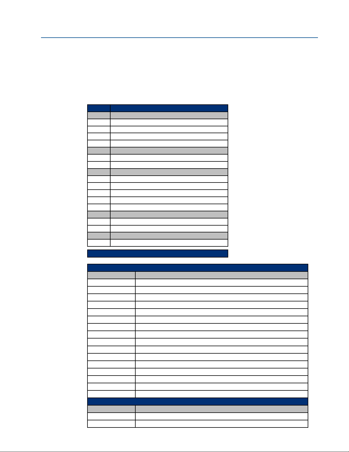
1.3 Ordering Information
The Clarity II is a complete system for the determination of turbidity in water. It consists of an
nalyzer and one or two sensors with a debubbler/measuring chamber assembly and cable for each
a
sensor. A calibration cup is available as an option. Because a sensor cannot be calibrated without a
calibration cup, at least one cup must be ordered. Calibration standard (formazin or polymer
spheres) must be ordered as a separate item.
T56 Turbidity System Components
ode
C
01 EPA Sensor
02 ISO Sensor
40 EPA Sensor (Second Sensor Option)
41 ISO Sensor (Second Sensor Option)
Code Measuring Chamber
10 Debubbler Flow Chamber
60 Two Debubbler Flow Chambers
Code Sensor Cable
20 20' (6.1 m)
21 50' (15.2 m)
23 One 20' (6.1 m), One 50' (15.2 m)
50 Two 20' (6.1 m)
51 Two 50' (15.2 m)
Code Instrument
30 Single Input (56-03-27-38-HT)
31 Dual Input (56-03-27-37-HT)
Code Optional
71 Calibration Cup (recommended for calibration)
ensor Type
S
Ordering Example With Codes: T56 -01 -10 -20 -30
Accessories
Part # Description
23554-00 Cable Gland Kit for Model 54e, XMT, 1055, 1056, Quantity 5
23820-00 Pipe/Wall Mounting Bracket for Models 1056, 1057, 5081, 6081, and XMT
23820-01 2” Pipe Mounting Bracket, Stainless Steel
9240048-00 S.S. Tag (specify marking)
24103-00 Flowmeter kit, includes valved rotameter and fittings
24101-00 Calibration cup
8-0108-0002-EPA Turbidity sensor EPA 180.1 compliant
8-0108-0003-ISO Turbidity sensor ISO 7027 compliant
1-0901-0009-EPA Replacement Lamp, EPA
1-0901-0010-ISO Replacement Lamp, ISO
24097-00 Sensor cable, turbidity, 20'
24098-00 Sensor cable, turbidity, 50'
24138-00 3' Turbidity Sensor Cable for Clarity II
24170-00 Molded debubbler with integral flow chamber
9550145 O-ring for sensor, external, fits molded debubbler
9550322 O-ring for upper and lower debubbler caps
Calibration Standards
Part # Description
060-761855 Premixed 4000 NTU Formazin calibration Kit
905-761854 Replacement solution for 4000 NTU premixed Kit
4 Description and Specifications
Page 11
Instruction Manual Clarity II T56
PN-51-T56 May 2012
Section 2.0 – Installation
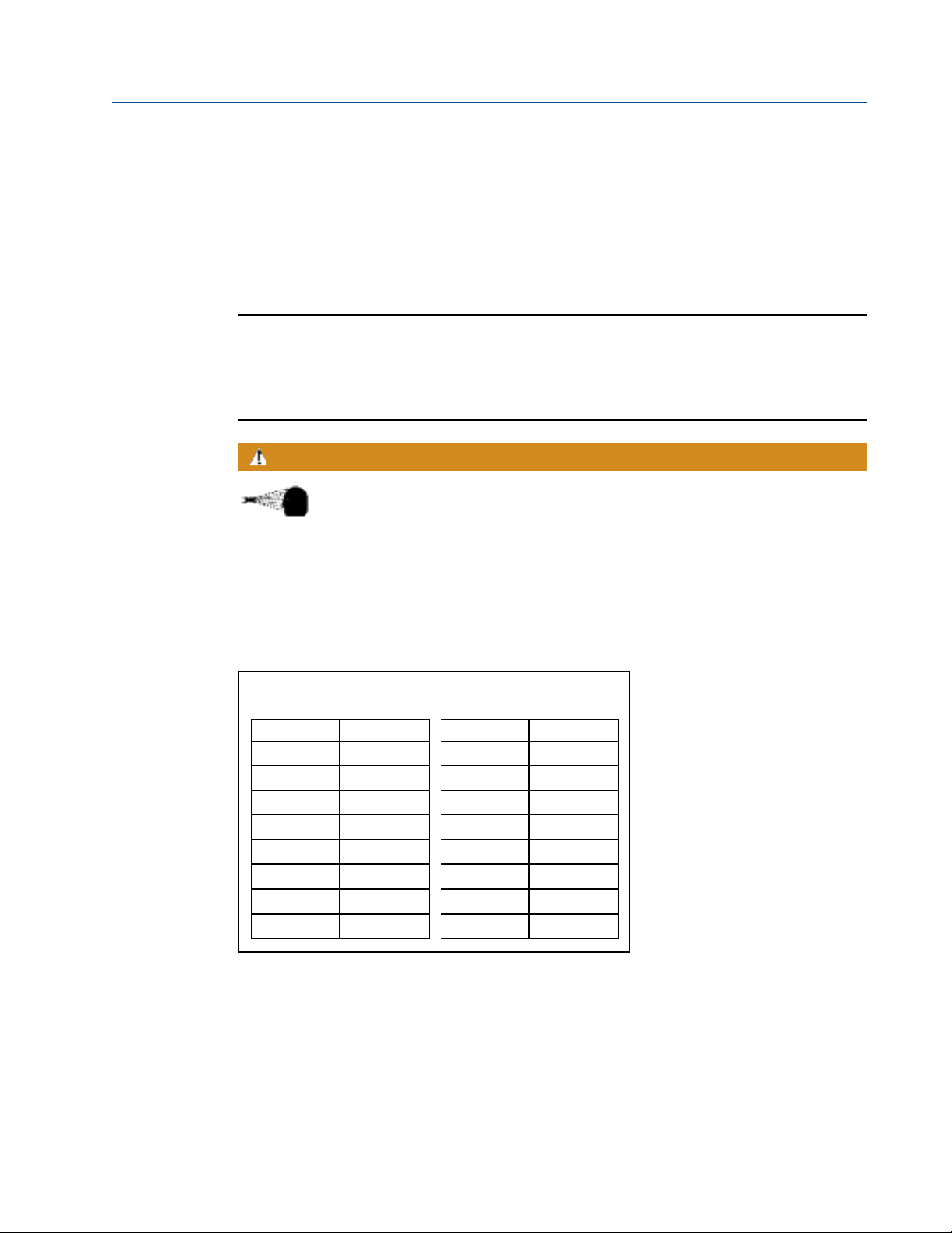
2.1 Unpacking and Inspection
The Clarity II Turbidimeter is a complete system for the determination of turbidity in drinking water.
The system consists of the analyzer, sensor(s), cable(s), and flow chamber/debubbler(s). Consult the
table to verify that you have received the parts for the option you ordered.
Item Model/part number
Single Input Turbidity Analyzer with HART 56-03-27-38-HT
Dual Input Turbidity Analyzer with HART 56-03-27-37-HT
Sensor-EPA standard 8-0108-0002-EPA
Sensor-ISO standard 8-0108-0003-ISO
Cable-3 ft (0.9 m) 24138-00
Cable-20 ft (6.1 m) 24097-00
Cable-50 ft (15.2 m) 24098-00
Calibration cup 24101-00
Molded chamber/debubbler 24170-00
2.2 Installation
2.2.1 General Information
1. Although the analyzer is suitable for outdoor use, do not install it in direct sunlight or in
areas of extreme temperatures.
2. Install the analyzer in an area where vibration and electromagnetic and radio frequency
interference are minimized or absent.
3. Keep the analyzer and sensor wiring at least one foot from high voltage conductors. Be sure
there is easy access to the analyzer.
4. The analyzer is suitable for panel, pipe, or surface mounting. Refer to the table below.
Type of Mounting Figure
Panel 2-1
Wall and Pipe 2-2
WARNING
RISK OF ELECTRICAL SHOCK
Electrical installation must be in accordance with the National Electrical Code
(ANSI/NFPA-70) and/or any other applicable national or local codes.
Installation 5
Page 12
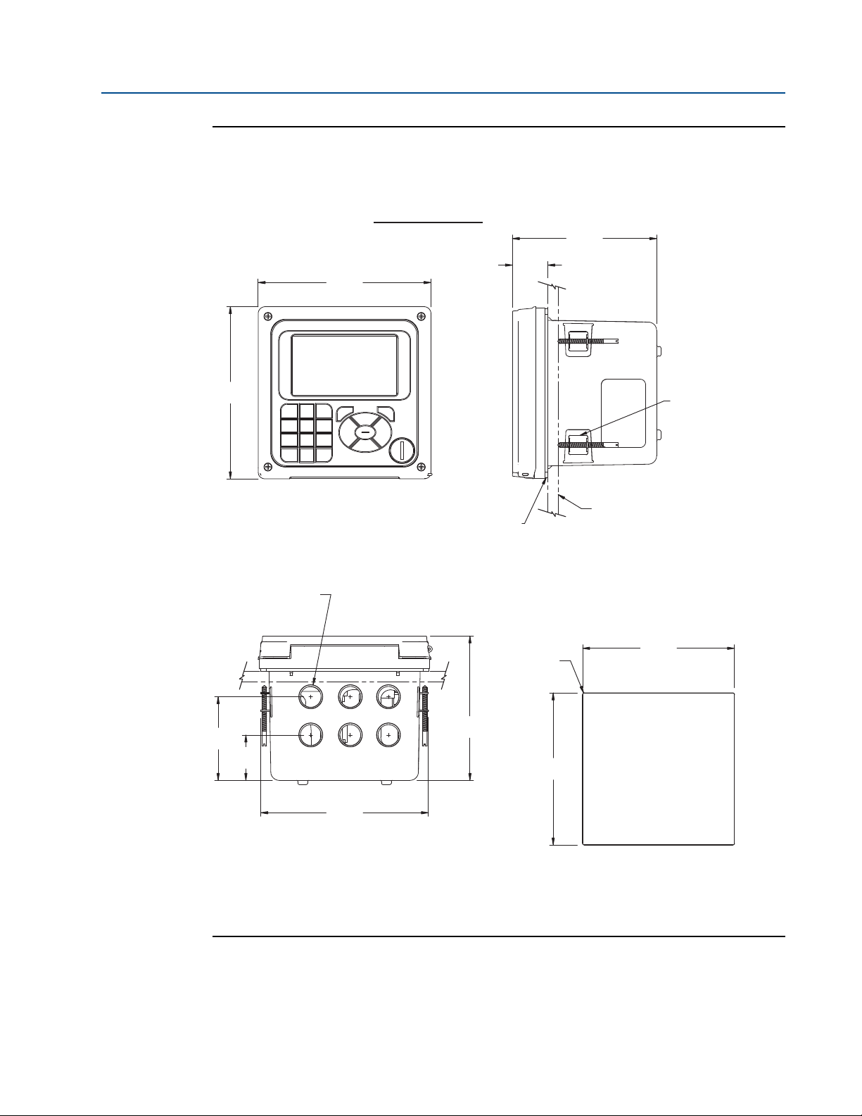
Instruction Manual Clarity II T56
PANEL SUPPLIED BY OTHERS
MAXIMUM THICKNESS
.375 IN (9.52 mm)
PANEL MOUNT GASKET
BOTTOM VIEW
FRONT VIEW
SIDE VIEW
PANEL CUT-OUT
6.20
157.5
6.17
1
56.8
5
.18
131.4
1
.27
32.2
5.45
138.4
5.45
138.4
6.01
152.7
1.62
41.2
3.00
76.1
5.18
131.4
4X MOUNTING
BRACKE TS
A
ND SCREWS
PROVIDED WITH
I
NSTRUMENT
O
.86
21.8
4X
CONDUIT OPENINGS
R
.06
1.5
MAXIMUM
PANEL MOUNT
PN-51-T56 May 2012
Fig. 2-1 T56 Panel Mounting Installation dimensions
6 Installation
Page 13
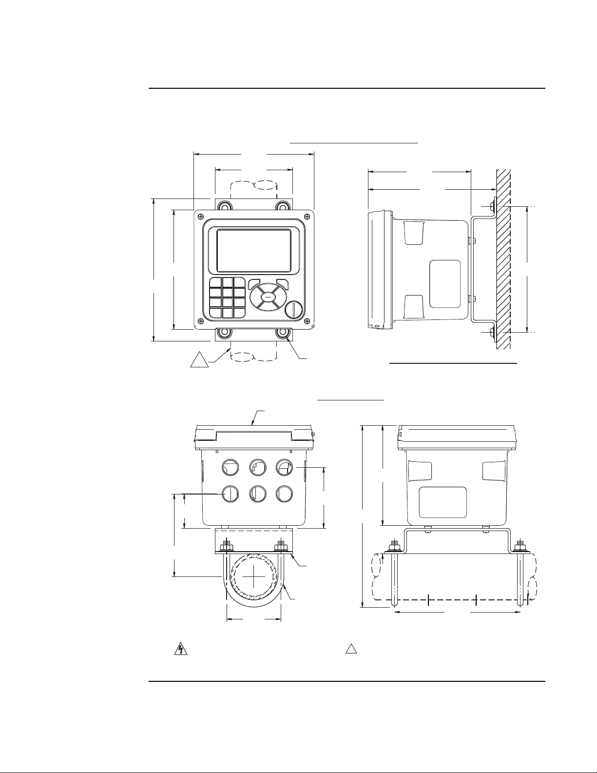
Instruction Manual Clarity II T56
NOTES: UNLESS OTHERWISE SPECIFIED
L
C
FRONT PANEL
2 INCH PIPE
MOUNT
BRACKE T
2X SET U-BOLTS
FOR 2" PIPE IN
KIT PN 23820-00
1 VERTICAL PIPE MOUNTING SHOWN. FOR HORIZONTAL
PIPE, ROTATE BRACKET AND U-BOLTS 90°.
BOTTOM VIEW
FRONT VIEW
SIDE VIEW
SIDE VIEW
6.50
1
65.1
5
.32
135.3
6.64
168.8
4
.00
1
01.6
6.20
157.5
6.17
1
56.8
7.37
187.2
4X COVER SCREW
WALL / SURFACE MOUNT
6.50
165.1
5.18
131.4
2.81
71.4
4.28
108.7
1.78
45.1
3.14
79.8
9.41
239.1
1.47
37.3
PIPE MOUNT
1
2" PIPE SUPPLIED
BY CUSTOMER
DO NOT OPERATE OR ENERGIZE INSTRUMENT WITH
CASE OPEN.
WALL / SURFACE MOUNT
PN-51-T56 May 2012
ig. 2-2 T56 Pipe and Wall Mounting Installation dimensions
F
Installation 7
Page 14
Instruction Manual Clarity II T56
PN-51-T56 May 2012
2.3 Installation – Debubbler Assembly
See Figure 2-3 for installation.
Connect the sample line to the inlet fitting. The fitting accepts 1/4-inch OD tubing. See Section
2.6 for recommended installation of the sample port.
Attach a piece of 3/8 inch ID soft tubing to the drain fitting. The debubbler must drain to atmosphere.
NOTE:
During operation, the debubbler is under pressure. A 0.040 inch (1 mm) orifice in the
outlet provides the pressure. Back pressure helps prevent outgassing, which can lead to
bubbles accumulating on the sensor face resulting in erroneous readings. DO NOT
EXCEED 30 psig (308 kPa abs) inlet pressure.
WARNING
Before removing the sensor, be absolutely certain that the process pressure
is reduced to 0 psig and the process temperature is lowered to a safe level!
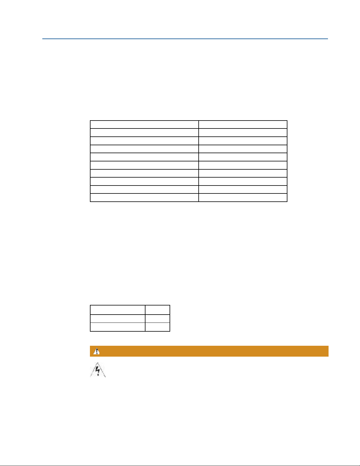
The amount of pressure in the debubbler can be estimated from the flow rate. See Table 2-1.
To control and monitor sample flow, a valved rotameter with fittings is available (PN 24103-00).
Attach the rotameter to the debubbler outlet. The rotameter can also be used to increase back
pressure on the debubbler if additional pressure is needed to prevent outgassing.
TABLE 2-1. Approximate debubbler pressure as a
function of flow (0.040 inch outlet orifice)
gph psig
21
43
68
8 14
10 21
11 26
12 31
––
mL/min kPa abs
100 110
200 120
300 140
400 160
500 190
600 240
700 280
800 340
8 Ordering Information
Page 15

Instruction Manual Clarity II T56
PN-51-T56 May 2012
ig. 2-3 Debubbler and Flow Chamber
F
Installation 9
Page 16

Instruction Manual Clarity II T56
PN-51-T56 May 2012
2.4 Installation – Sensor
Unscrew the nut on the side of the debubbler. Insert the sensor in the mouth of the measuring
chamber. Be sure the pin on the debubbler lines up with the hole in the sensor. Replace the nut.
Remove the protective cap from the sensor and screw the cable onto the receptacle. The plug and
receptacle are keyed for proper alignment.
The sensor is rated to IP65 when properly connected to the cable. To prevent possible water
damage to the connector contacts, be sure the cable receptacle and the connector on the back of
the sensor are dry when connecting or disconnecting the cable.
Fig. 2-4 Sensor
10
Page 17

Instruction Manual Clarity II T56
PN-51-T56 May 2012
Section 3.0 Wiring
3.1 General
The T56 is easy to wire. It includes removable connectors and slide-out signal input boards. The
front panel is hinged at the bottom. The panel swings down for easy access to the wiring locations.
3.1.1. Removable connectors and signal input boards
The T56 uses removable signal input boards and communication boards for ease of wiring and
installation. Each of the signal input boards can be partially or completely removed from the
enclosure for wiring. The T56 has three slots for placement of up to two signal input boards and
one communication board
Slot 1-Left Slot 2 – Center Slot 3 – Right
Profi board Signal Board 1 Signal Board 2
3.1.2. Signal input boards
Slots 2 and 3 are for signal input measurement boards. Wire the sensor leads to the measurement
board following the lead locations marked on the board. After wiring the sensor leads to the signal
board, carefully slide the wired board fully into the enclosure slot and take up the excess sensor
cable through the cable gland. Tighten the cable gland nut to secure the cable and ensure a sealed
enclosure.
NOTE:
For the purpose of replacing factory-installed signal input boards, Rosemount Analytical Inc. is
the sole supplier.
3.1.3. Digital communication boards
HART digital communications is standard on the T56. A Profibus DP communication board is
available as an option for the T56 communication with a host. HART communications supports
Bell 202 digital communications over an analog 4-20mA current output. Profibus DP is an open
communications protocol which operates over a dedicated digital line to the host.
3.1.4 Alarm relays
Four alarm relays are supplied with the switching power supply (85 to 264VAC, -03 order code)
and the 24VDC power supply (20-30VDC, -02 order code). All relays can be used for process
measurement(s) or temperature. Any relay can be configured as a fault alarm instead of a process
alarm. Each relay can be configured independently and each can be programmed as an interval
timer, typically used to activate pumps or control valves. As process alarms, alarm logic (high or
low activation or USP*) and deadband are user-programmable. Customer-defined failsafe
operation is supported as a programmable menu function to allow all relays to be energized or
not-energized as a default condition upon powering the analyzer. The USP* alarm can be
programmed to activate when the conductivity is within a user-selectable percentage of the
limit. USP alarming is available only when a contacting conductivity measurement board is
installed.
Wiring 11
Page 18

Instruction Manual Clarity II T56
PN-51-T56 May 2012
3.2 Preparing Conduit Openings
There are six conduit openings in all configurations of T56. (Note that four of the openings will
e fitted with plugs upon shipment.)
b
Conduit openings accept 1/2-inch conduit fittings or PG13.5 cable glands. To keep the case watertight, block unused openings with NEMA 4X or IP65 conduit plugs.
NOTE:
Use watertight fittings and hubs that comply with your requirements. Connect the conduit hub
to the conduit before attaching the fitting to the analyzer.
3.3 Preparing Sensor Cable
The T56 is intended for use with all Rosemount Analytical sensors. Refer to the sensor
installation instructions for details on preparing sensor cables.
3.4 Power, Output, and Sensor Connections
3.4.1 Power wiring
Two Power Supplies are offered for the T56:
a. 24VDC (20 – 30V) Power Supply (-02 ordering code)
b. 85 – 265 VAC Switching Power Supply (-03 ordering code)
AC mains leads and 24VDC leads are wired to the Power Supply board which is mounted vertically
on the left side of the main enclosure cavity. Each lead location is clearly marked on the Power Supply
board. Wire the power leads to the Power Supply board using the lead markings on the board.
The grounding plate is connected to the earth terminal of the -03 (85-265VAC) power supply.
The green colored screws on the grounding plate are intended for connection to some sensors
to minimize radio frequency interference. The green screws are not intended to be used for
safety purposes.
3.4.2 Current output wiring
All instruments are shipped with four 4-20mA current outputs. Wiring locations for the outputs
are on the Main board which is mounted on the hinged door of the instrument. Wire the output
leads to the correct position on the Main board using the lead markings (+/positive, -/negative)
on the board. Male mating connectors are provided with each unit.
3.4.3 Alarm relay wiring
Four alarm relays are supplied with the switching power supply (85 to 265VAC, -03 order code)
and the 24VDC power supply (20-30VDC, -02 order code). Wire the relay leads on each of the
independent relays to the correct position on the power supply board using the printed lead
markings (NO/Normally Open, NC/Normally Closed, or Com/Common) on the board.
12 Wiring
Page 19

Instruction Manual Clarity II T56
PN-51-T56 May 2012
3.4.4 Sensor wiring to signal boards
Plug the pre-terminated sensor cable connector directly into the turbidity signal board mating
connector.
WARNING
RISK OF ELECTRICAL SHOCK
Electrical installation must be in accordance with the National Electrical Code
(ANSI/NFPA-70) and/or any other applicable national or local codes.
3.4.5 Sensor
The sensor cable is pre-wired to a plug that inserts into a receiving socket on the signal board.
See Figures 3-1. The cable also passes through a strain relief fitting. To install the cable:
1. Remove the wrenching nut from the strain relief fitting.
2. Insert the plug through the hole in the bottom of the enclosure nearest the sensor socket.
Seat the fitting in the hole.
3. Slide the wrenching nut over the cable plug and screw it onto the fitting.
4. Loosen the cable nut so the cable slides easily.
5. Insert the plug into the appropriate receptacle. To remove the plug, squeeze the release
clip and pull straight out.
6. Adjust the cable slack in the enclosure and tighten the cable nut. Be sure to allow sufficient
slack to avoid placing stress on the cable and connections.
7. Plug the cable into the back of the sensor. The sensor is rated to IP65 when properly
connected to the cable. To prevent possible water damage to the connector contacts, be
sure the cable receptacle and the connector on the back of the sensor are dry when
connecting or disconnecting the cable.
8. Place the sensor in either the measuring chamber or the calibration cup. The sensor must
be in a dark place when power is first applied to the analyzer.
NOTE:
If “S1 Warning” appears, check sensor cable connection and confirm sample water
flow at debubbler drain outlet.
Wiring 13
Page 20

Instruction Manual Clarity II T56
PN-51-T56 May 2012
ig. 3-1 Turbidity signal board with plug-in Sensor connection
F
IMPORTANT NOTE:
When using EPA/incandescent sensors (PN 8-0108-0002-EPA):
• DO NOT power up the instrument without the sensor connected
• DO NOT disconnect and reconnect a sensor while an analyzer is powered
If this is inconvenient or cannot be avoided:
1. Cycle power to the instrument after connecting the sensor or...
2. Perform a Slope Calibration or Standard Calibration routine after connecting the
sensor.
Following these guidelines will extend the life of the incandescent lamp and avoid
premature warnings and faults due to reduced lamp life.
14
Page 21

Instruction Manual Clarity II T56
PN-51-T56 May 2012
Section 4.0 Display and Operation
4.1 User Interface
The T56 has a large display which shows two
live measurement readouts in large digits and
up to six additional process variables or diagnostic parameters concurrently. The display is
back-lit and the format can be customized to
meet user requirements. The ENTER/MENU
key allows access to Calibration, Hold (of
current outputs), Programming, Display, Data
and HART functions. In addition, a dedicated
INFO key is available to provide access to
useful diagnostic and instrument information
regarding installed sensor(s) and any problematic conditions. The display flashes a red
banner to indicate a Fault condition and a
yellow banner for a Warning condition. Help
screens are displayed for fault and warning
conditions to guide the user in troubleshooting. During calibration and programming, key presses
guide the user step-by-step through procedures. An alpha-numeric keypad similar to a cell phone
keypad is available to allow the user to enter data during programming and calibration or lengthy
tags to describe process points, sensors, or instrumentation.
4.2 Instrument Keypad
There are three Function keys, four Navigation keys and an alpha-numeric keypad on the
instrument keypad.
Function keys
The ENTER/MENU key is used to access menus for programming and calibrating the instrument as well as retrieving stored data. Eight top-level menu items appear when pressing the
ENTER/MENU key from the main display of live readings:
• Calibrate: calibrate attached sensors and analog outputs.
• Program: Program outputs, relays, measurement, temperature, and security codes.
• Hold: Suspend current outputs.
• Display Setup: Program graphic trend display, brightness, main display format, tags,
language, and warnings.
• Data storage and retrieval: Enable data and event storage, download data, and view events.
• HART or Profibus: Program HART and Profibus communication parameters.
• Time and Date: Set and view real-time clock settings.
• Reset:Reset all instrument settings, calibration settings or current outputs to factory defaults.
Calibrate
Program HART
Hold Time and Date
Display setup Reset
Data storage and retrieval
Display and Operation 15
Page 22

Instruction Manual Clarity II T56
PN-51-T56 May 2012
TheENTER/MENU keyis also used to enter selections or enable programming and calibration steps.
The EXIT key returns to the previous menu level.
The INFO key provides detailed instructions and explanations during programming and calibrating
procedures. It also provides troubleshooting tips for all faults and warnings that may occur during
calibration or continuous operation in process.
Navigation Keys
The four Navigation keys arranged around the ENTER/MENU key operate in an intuitive
manner similar to the navigation keys on a computer keyboard. During menu operation, these
keys are used to move the highlighted screen selection to another adjacent screen item. During
tag entry, the left key is used to delete entries during active alpha-numeric character entry.
Alpha-numeric Keypad
The alpha-numeric keypad has 12 keys as outlined below.
• Nine keys are alpha-numeric
• One key is a dedicated “1” key
• One key is a dedicated “0” key
• One key is a dedicated “.” (decimal point) key
The alpha-numeric keypad operates the same as entries on a mobile phone. The nine alpha-
numeric keys have multiple characters that can be entered for tag entries or during programming
and calibration steps. Character selections are made by pressing the key multiple times to toggle
to characters that are available on each key.
4.3 Main Display
The T56 displays one or two primary measurement values, up to six secondary measurement
values, fault and warning banner, alarm relay flags, and a digital communications icon.
Process Measurements:
Two process variables are displayed if two signal boards are installed. One process variable and
process temperature is displayed if one signal board is installed with one sensor. The Upper
display area shows the Sensor 1 process reading. The Center display area shows the Sensor 2
process reading. For dual conductivity, the Upper and Center display areas can be assigned to
different process variables as follows:
For single input configurations, the Upper display area shows the live process variable and the
Center display area can be assigned to Temperature or blank.
Secondary Values:
Up to six secondary values are shown in six display quadrants at the bottom half of the screen.
All six secondary value positions can be programmed by the user to any display parameter
available.
16 Display and Operation
Page 23

Instruction Manual Clarity II T56
PN-51-T56 May 2012
4.4 Menu System
The T56 menu system is similar to a computer. Pressing the ENTER/MENU key at any time
pens the top-level menu including Calibration, Hold, Programming, Display, Data and HART
o
functions. To find a menu item, use the directional Navigation keys to highlight a menu item.
Press ENTER/MENU and simply direct the cursor to the desired operation and follow the screen
prompts. Pressing the BACK screen control available on some menu screens will revert to the
immediate previous menu screen. Pressing the EXIT key will return to the previous hierarchical
menu level.
Fault and Warning banner:
If the analyzer detects a problem with itself or the sensor the word Fault banner (red) and/or
Warning banner (yellow) will appear at the bottom of the main display. A fault requires immediate
attention. A warning indicates a problematic condition or an impending failure. For detailed
troubleshooting assistance, press INFO.
Display and Operation 17
Page 24

Instruction Manual Clarity II T56
PN-51-T56 May 2012
18
This page left blank intentionally
Page 25

Instruction Manual Clarity II T56
PN-51-T56 May 2012
Section 5.0. Programming the Analyzer - Basics
5.1 General
Typical programming steps include the following listed procedures. Each of these programming
functions are easily and quickly accomplished using the intuitive menu systems.
• Configure and assign values to the current outputs
• Set a security code for two levels of security access
• Accessing menu functions using a security code
• Enabling and disabling Hold mode for current outputs
• Choosing the frequency of the AC power (needed for optimum noise rejection)
• Resetting all factory defaults, calibration data only, or current output settings only
5.2 Configuring and Ranging the Current Outputs
The T56 accepts inputs from two sensors
and has four analog current outputs. Ranging
the outputs means assigning values to the
low (0 or 4 mA) and high (20 mA) outputs.
This section provides a guide for configuring
and ranging the outputs. ALWAYS
CONFIGURE THE OUTPUTS FIRST.
To configure the outputs, access the Outputs
screen by pressing ENTER/MENU then
Program from the main screen. Outputs 1-4
can be set to Analog, PID or Simulation. Also, output assignments, scaling the range, linear or logarithmic outputs, output dampening, output setpoints and output fault levels can be set for each
output if desired.
5.3 Setting a Security Code
The security codes prevent accidental or unwanted changes to program settings, displays,
and calibration. T56 has two levels of security code to control access and use of the
instrument to different types of users. The
two levels of security are:
• All: This is the Supervisory security
level. It allows access to all menu
functions, including Programming,
Calibration, Hold and Display.
• Calibration/Hold: This is the oper-
ator or technician level menu. It
allows access to only calibration and
Hold of the current outputs.
The set security codes, access the Security screen by pressing ENTER/MENU from the main
screen. Upon entry of the proper code, the follow security screen will appear.
Programming Basics 19
Page 26

Instruction Manual Clarity II T56
PN-51-T56 May 2012
5.4 Security Access
When entering the correct access code for the Calibration/Hold security level, the Calibration
nd Hold menus are accessible. This allows operators or technicians to perform routine mainte-
a
nance. This security level does not allow access to the Program or Display menus. When
entering the correct access code for All
security level, the user has access to all
menu functions, including Programming,
Calibration, Hold and Display.
To use T56 menus using a security code,
access the Security screen by pressing
ENTER/MENU from the main screen. If a security code is currently programmed, the follow
security screen will appear. Enter the code.
1. If a security code has been
programmed, selecting the Calibrate, Hold, Program or Display top menu items causes
the security access screen to appear
2. Enter the three-digit security code for the appropriate security level.
3. If the entry is correct, the appropriate menu screen appears. If the entry is incorrect, the
Invalid Code screen appears. The Enter Security Code screen reappears after 2 seconds.
5.5 Using Hold
To prevent improper operation of systems
or pumps that are controlled directly by the
current output, place the analyzer in hold
before removing the sensor for calibration
and maintenance. During hold, all outputs
remain at the last value. Once in hold, all
current outputs remain on Hold indefinitely. Be sure to remove the analyzer from
hold once calibration is complete
To hold the outputs and alarm relays,
access the Hold screen by pressing
ENTER/MENU from the main screen.
5.6 Resetting Factory Default Settings
This section describes how to restore factory calibration and default values. The process also
clears all fault messages and returns the
display to the first Quick Start screen. The
T56 offers three options for resetting
factory defaults.
a. reset all settings to factory defaults
b. reset sensor calibration data only
c. reset analog output settings only
20 Programming Basics
Page 27

Instruction Manual Clarity II T56
PN-51-T56 May 2012
To reset to factory defaults, reset calibration data only or reset analog outputs only, access the
Reset screen by pressing ENTER/MENU from the main screen.
5.7 Programming Alarm Relays
The T56 24VDC (-02 order code) and the AC switching power supply (-03 order code) provide four
alarm relays for process measurement or temperature. Each alarm can be configured as a fault
alarm instead of a process alarm. Also, each relay can be programmed independently and each can
be programmed as an interval timer or one
of four advanced timer functions. This
section describes how to configure alarm
relays, simulate relay activation, and
synchronize timers for the four alarm relays.
This section provides details to program
the following alarm features. To program
the alarm relays, access the Program
screen by pressing ENTER/MENU from the
main screen and then select the Relay tab
and the Configure relay control.
The following relay functions can be programmed to any relay from the Configure Relay
screen:
1. assign a relay
2. define a relay function
3. assign a Measurement
4. set relay logic
5. enter setpoints
6. set deadband
7. set normal state
8. set USP Safety level (contacting conductivity)
To program these relay functions, access the Configure Relay screen by pressing ENTER/MENU
from the main Relay programming screen.
1. To assign a relay, highlight the desired
Relay 1-4 and press ENTER/MENU.
2. To define a relay function, select from
Setpoint, Interval Timer, TPC, Bleed
and Feed, Water Meter, Delay timer,
Date and Time, Fault or None and press
ENTER/MENU.
3. To assign a measurement to a specific
relay, select the desired measurement
or temperature input and press
ENTER/MENU.
4. To set relay logic to activate alarms at a High reading or a Low reading, select high
or low and press ENTER/MENU.
Programming Basics 21
Page 28

Instruction Manual Clarity II T56
PN-51-T56 May 2012
5. To enter setpoints for relays, enter the desired value for the process measurement
or temperature at which to activate an alarm event and press ENTER/MENU.
6. To set deadband as a measurement value, enter the change in the process value needed
after the relay deactivates to return to normal (and thereby preventing
epeated alarm activation) and press ENTER/MENU.
r
7. To set the Normal alarm condition, select Open or Closed and press ENTER/MENU.
Program the normal state to define the desired alarm default state to normally
open or normally closed upon power up.
8. To set USP Safety, enter the percentage below the limit at which to activate the alarm and
press ENTER/MENU. NOTE: USP Safety only appears if a contacting
conductivity board is installed.
This section provides details to simulate
relay action. To simulate relays, access the
Program screen by pressing ENTER/MENU
from the main screen and then select the
Relay tab.
To simulate alarm relay conditions,
access the Simulate Relay Action screen
by pressing ENTER/MENU from the main
Relay programming screen.
Alarm relays can be manually set for the
purposes of checking devices such as valves
or pumps. Under the Alarms
Settings menu, this screen will appear to
allow manual forced activation of the
alarm relays. Select the desired alarm
condition to simulate.
22 Programming Basics
Page 29

Instruction Manual Clarity II T56
PN-51-T56 May 2012
Section 6.0 Programming - Turbidity
6.1 Programming Measurements – Introduction
The T56 automatically recognizes each installed measurement board upon first power-up and
each time the analyzer is powered. Completion of Quick Start screens upon first power
up enable measurements, but additional steps may be required to program the analyzer for the
desired measurement application.
6.2 Turbidity Measurement Programming
This section describes how to configure the T56 analyzer for Turbidity measurements. The
following programming and configuration functions are covered.
1. Measurement type: Turbidity Select Turbidity or TSS calculation (estimated TSS)
2. Sensor type: Select EPA or ISO
3. Measurement units: NTU, FTU, FNU
4. Filter: 20 sec Override the default input filter, enter 0-999 seconds
5. Bubble Rejection: On Intelligent software algorithm to eliminate erroneous readings
caused by bubble accumulation in the sample
1. To program the Measurement type,
Select Turbidity or TSS
calculation (estimated TSS)
and press ENTER/MENU.
2. To program the Sensor type:
Select EPA or ISO and press
ENTER/MENU.
3. To program Measurement units: NTU,
FTU, FNU and press ENTER/MENU.
4. To Override the default input filter,
enter 0-999 seconds and press ENTER/MENU.
5. To program Bubble Rejection, select On or Off and press ENTER/MENU.
Programming Measurements 23
Page 30

Instruction Manual Clarity II T56
PN-51-T56 May 2012
24
This page left blank intentionally
Page 31

Instruction Manual Clarity II T56
PN-51-T56 May 2012
Section 7.0 Calibration
7.1 Calibration – Introduction
Calibration is the process of adjusting or standardizing the analyzer to a lab test or a calibrated
laboratory instrument, or standardizing to some known reference. Completion of Quick Start
upon first power up enables live measurements but does not ensure accurate readings in the
lab or in process. Calibration should be performed with each attached sensor to ensure accurate, repeatable readings.
7.2 Turbidity
This section describes how to calibrate the turbidity sensor against a user-prepared standard as
a 2-point calibration with deionized water, against a 20 NTU user-prepared standard as a single
point calibration, and against a grab sample using a reference turbidimeter.
To calibrate the turbidity sensor, access the Calibration screen by pressing ENTER/MENU from the
main screen, select S1 or S2 Measurement and press ENTER/MENU. Press INFO at any time to learn
more about this procedure. A yellow screen will appear with detailed instructions and information.
The following calibration routine is covered:
1. Slope Calibration Slope cal with pure
water and a standard of known
turbidity
2. Standardize Calibration
Standardizing the sensor to a known
turbidity
3. Grab Calibration Standardizing the
sensor to a known turbidity based on a
reference turbidimeter
1. To calibrate the turbidity loop using Slope Calibration with pure water and a standard of
known turbidity, follow the step-by-step procedures displayed on-screen.
2. To calibrate the turbidity loop using Standardize Calibration by Standardizing the sensor to
a known turbidity, follow the step-by-step procedures displayed on-screen.
3. To calibrate the turbidity loop using Grab Calibration by Standardizing the sensor to a
known turbidity based on a reference turbidimeter, follow the step-by-step procedures
displayed on-screen.
Calibration 25
Page 32

Instruction Manual Clarity II T56
PN-51-T56 May 2012
7.2.1 Slope Calibration – Turbidity
This section describes how to conduct a 2-point calibration of the turbidity sensor against a
user-prepared 20NTU standard. The calibration requires two steps. First, immerse the sensor in
iltered water having very low turbidity and measure the sensor output. Next, increase the
f
turbidity of the filtered water by a known amount, typically 20 NTU, and measure the sensor
output again. The analyzer takes the two measurements, applies a linearization correction (if
necessary), and calculates the sensitivity. Sensitivity is the sensor output (in mV) divided by
turbidity. A typical new sensor has a sensitivity of about 10 mV/NTU. As the sensor ages, the
sensitivity decreases. The figure below illustrates how turbidity calibration works. Before
beginning the calibration, the analyzer does a dark current measurement. Dark current is the
signal generated by the detector when no light is falling on it. The analyzer subtracts the dark
current from the raw scattered light signal and converts the result to turbidity. In highly filtered
samples, which scatter little light, the dark current can be a substantial amount of the signal
generated by the detector.
7.2.2 Standardize Calibration – Turbidity
The turbidity sensor can also be calibrated against a commercial standard. Stable 20.0 NTU
standards are available from a number of sources. Calibration using a commercial standard is
simple. Filtered deionized water is not required. Before beginning the calibration, the analyzer
does a dark current measurement. Dark current is the signal generated by the detector even
when no light is falling on it. The analyzer subtracts the dark current from the raw scattered
light signal and converts the result to turbidity. In highly filtered samples, which scatter little
light, the dark current can be a substantial amount of the signal generated by the sensor.
7.2.3 Grab Calibration – Turbidity
If desired, the turbidity sensor can be calibrated against the turbidity reading from another
instrument. The analyzer treats the value entered by the user as though it were the true
turbidity of the sample. Therefore, grab sample calibration changes the sensitivity, it does not
apply an offset to the reading.
26 Calibration
Page 33

Instruction Manual Clarity II T56
PN-51-T56 May 2012
Section 8.0 Maintenance
8.1 Overview
The 56 Analyzer used in the Clarity II turbidimeter needs little routine maintenance. Clean the
analyzer case and front panel by wiping it with a clean soft cloth dampened with water ONLY. Do
not use solvents, like alcohol, that might cause a buildup of static charge.
A few of the components of the analyzer are replaceable. See Tables 8-1 and 8-2.
WARNING
Explosion Hazard. Do not disconnect equipment when a flammable or combustible
atmosphere is present.
8.2 Sensor
8.2.1 Cleaning the sensor
Clean the sensor by rinsing it with water followed by wiping with a soft tissue. If water is inadequate, wash with a mild detergent solution followed by thorough rinsing with water. Do not
scratch the lamp or photodiode windows.
If mineral scale is present, use a dilute acid solution applied with a cotton swab to clean away
the deposit. Rinse thoroughly with water.
Do not use abrasive cleaners or solvents.
8.2.2 Replacing the lamp/LED board
The USEPA-compliant sensor uses a tungsten filament lamp (PN 1-0901-0004-EPA) as the light
source. The lamp has an expected life of about one year. The ISO-compliant version uses an
infrared LED (PN 1-0901-0005-ISO). Its expected life is five years. The 56 analyzer continuously
monitors the source intensity and corrects for changes in source intensity caused by age. When
the source intensity becomes too low, the analyzer warns the user. The user should replace the
lamp as soon as possible.
To replace the lamp/LED board:
1. Turn off power to the analyzer.
WARNING
Explosion Hazard. Do not disconnect equipment when a flammable or combustible
atmosphere is present.
2. Remove the sensor from the measuring chamber and disconnect the cable.
WARNING
Before removing the sensor, be absolutely certain that the process pressure
is reduced to 0 psig and the process temperature is lowered to a safe level!
Maintenance 27
Page 34

Instruction Manual Clarity II T56
PN-51-T56 May 2012
NOTE:
f you have a dual input analyzer, you can reapply power at this point. The initial reading
I
from the other sensor will be momentarily zero. After about 60 seconds the reading will
reach its final value.
3. Using a small Phillips screwdriver,
remove the two screws holding the
Fig. 8-1 Replacing the Lamp/LED Board
top flange of the sensor to the
body.
Step 4
4. Using a slight back and forth
twisting motion carefully pull the
flange from the sensor body. You
are pulling against a single O-ring
seal. Don’t pull too hard.
5. Using your thumb and forefinger,
remove the lamp/LED circuit board
from the sensor.
6. Insert the replacement board in the
sensor and push the socket on the
Step 5
replacement board into the mating
pins in the sensor.
7. Place the desiccant package in the
sensor body.
8. Orient the flange so that the screw
holes line up with the holes in the
sensor body. Push the flange back
on the sensor body and replace the
screws. Don’t let wires push on
lamp board. It may be necessary to
turn the flange a small amount
until the holes line up.
Step 6
9. Place the sensor in the calibration
cup and reconnect the cable.
10. Calibrate the sensor using either
slope or standard calibration
(Section 6.2 or 6.3). Do not use
grab calibration. Failure to calibrate
the sensor may reduce the life of
the sensor. See Sections 8.2.5 and
8.2.6.
28 Maintenance
Page 35

Instruction Manual Clarity II T56
PN-51-T56 May 2012
8.3 Debubbler and Measuring Chamber
8.3.1 Cleaning the sensor
1. Turn off the sample supply to the debubbler.
WARNING
BEFORE DISCONNECTING THE SAMPLE AND DRAIN LINES OR REMOVING THE
SENSOR, be absolutely certain the process pressure is reduced to 0 psig and
the process temperature is at a safe level.
2. Remove the sensor and put it in a safe place. The calibration cup is a good place to store
the sensor.
3. Loosen the small drain plug in the base plug and allow the sample in the debubbler to drain
out. See Figure 8-4. Replace the drain plug.
4. Unscrew the upper and lower caps. Be careful not to lose the O-rings.
5. Use a stream of water, a brush, or a rag to flush and clean out the inside of the debubbler
and measuring chamber.
6. Inspect the O-rings for signs of damage and replace if necessary. The part number for the
O-ring (one each) is 9550316.
7. Replace the upper and lower caps.
8. Replace the sensor.
8.3.2 Cleaning the orifice
1. Turn off the sample to the debubbler.
2. Disconnect the drain line. Unscrew the drain fitting from the orifice; then unscrew the
orifice from the debubbler body. See Figure 8-4.
3. Use a stream of water to flush out any residue accumulated in the orifice. Direct the stream
of water counter to the normal flow through the orifice.
4. If the material plugging the orifice cannot be removed with flushing, use a toothpick or a
stiff wire to push out the obstruction. Push counter to the normal flow through the orifice.
5. Reinstall the orifice and reconnect the drain line. Turn on the sample flow.
6. If the blockage cannot be removed or the orifice is damaged during cleaning, replace the
orifice (PN 33947-00).
Maintenance 29
Page 36

Instruction Manual Clarity II T56
PN-51-T56 May 2012
8.4 List of Replacement Parts
Fig. 3-2 Molded Debubbler Assembly
LOCATION IN
FIGURE 8-4 NUMBER
— Replacement lamp board assembly, USEPA-compliant sensor 1-0901-0009-EPA
— Replacement lamp board assembly, ISO-compliant sensor 1-0901-0010-ISO
— Replacement sensor, USEPA-compliant 8-0108-0002-EPA
— Replacement sensor, ISO-compliant 8-0108-0003-ISO
1 Debubbler housing 34015-00
2 Upper cap for debubbler 34014-00
3 Lower cap for debubbler 34014-01
4 Sensor nut 34014-02
5 Pipe plug, 1/4 inch MNPT ( 2 places) 3000854
6 Orifice assembly 33947-00
7 Sample inlet elbow, 1/4 in compression fitting x 1/4 in MNPT 9321010
8 Sample drain elbow, 3/8 in barb x 1/4 in MNPT 9322036
9 O-ring, one each, for upper and lower caps 9550322
not shown O-ring, one each, for sensor 9550145
30 Maintenance
DESCRIPTION
PART
Page 37

Instruction Manual Clarity II T56
PN-51-T56 May 2012
Section 9.0 Return of Material
9.1 General
To expedite the repair and return of instruments, proper communication between the
customer and the factory is important. Before returning a product for repair, call 1-949-7578500 for a Return Materials Authorization (RMA) number.
9.2 Warranty Repair
The following is the procedure for returning instruments still under warranty:
1. Call Rosemount Analytical for authorization.
2. To verify warranty, supply the factory sales order number or the original purchase order
number. In the case of individual parts or sub-assemblies, the serial number on the unit
must be supplied.
3. Carefully package the materials and enclose your “Letter of Transmittal” (see Warranty). If
possible, pack the materials in the same manner as they were received.
4. Send the package prepaid to:
Rosemount Analytical
2400 Barranca Parkway
Irvine, CA 92606
Attn: Factory Repair
RMA No. ____________
Mark the package: Returned for Repair
Model No. ____
9.3 Non-Warranty Repair
The following is the procedure for returning for repair instruments that are no longer
under warranty:
1. Call Rosemount Analytical for authorization.
2. Supply the purchase order number, and make sure to provide the name and telephone
number of the individual to be contacted should additional information be needed.
3. Do Steps 3 and 4 of Section 9.2.
NOTE
Consult the factory for additional information regarding service or repair.
Maintenance 31
Page 38

Instruction Manual Clarity II T56
PN-51-T56 May 2012
Appendix
This procedure describes how to verify linearity between turbidity and TSS.
1. Collect a sample of the process liquid-you may need 10 L or more if you use the Clarity II for measuring turbidity. If
you use a laboratory turbidimeter, you will need less volume. The Clarity II requires about 500 mL for the measurement; laboratory turbidimeters require 50 mL or less. Verify that the turbidity of the sample is less than 200 NTU.
Store in a clean bottle.
2. Filter a portion of the sample to obtain at least 5 L of dilution liquid. The filtrate is needed to dilute the sample in
subsequent steps. Verify that the turbidity of the dilution water is low. If filtering the sample is impractical, use
deionized water for dilution.
3. Measure the total suspended solids (TSS) in the sample obtained in step 1. Thoroughly mix the sample before
withdrawing liquid. A magnetic stirrer is best, but inverting the sample repeatedly for about a minute works, too.
Avoid violent shaking or mixing. Refer to any standard reference work on water and wastewater testing for the
procedure for determining TSS.
4. Dilute the sample from step 1, by a factor of 0.9, 0.7, 0.5, 0.3, and 0.1. See the table for recommended volumes.
Measure TSS and turbidity for each dilution. For lower TSS values, use a larger volume of sample.
Dilution Volume of Final Volume for Volume for
factor stock, mL volume, mL Clarity II, mL TSS, mL
1.00 -- -- 500 50 - 250
0.9 900 1000 500 50 - 250
0.7 700 1000 500 50 - 250
0.5 500 1000 500 50 - 250
0.3 300 1000 500 50 - 250
0.1 100 1000 500 50 - 250
5. Plot the data obtained in step 4, with turbidity on the y-axis and TSS on the x-axis. Fit the best straight line to the
data.
6. Locate two points (P1 and P2) on the line separated as much as possible. Read the ppm and NTU value for each
point and enter these into the analyzer. See Section 6.5.2.
32 Appendix
Page 39

Instruction Manual Clarity II T56
PN-51-T56 May 2012
WARRANTY
Seller warrants that the firmware will execute the programming instructions provided by Seller, and that the Goods manufactured or Services provided by Seller will be free from defects in materials or workmanship under normal use and care until the expiration of the applicable warranty period. Goods are warranted for twelve (12) months from the date of initial installation or eighteen (18) months from the
date of shipment by Seller, whichever period expires first. Consumables, such as glass electrodes, membranes, liquid junctions, elec-
trolyte, o-rings, catalytic beads, etc., and Services are warranted for a period of 90 days from the date of shipment or provision.
Products purchased by Seller from a third party for resale to Buyer ("Resale Products") shall carry only the warranty extended by the original manufacturer. Buyer agrees that Seller has no liability for Resale Products beyond making a reasonable commercial effort to arrange
for procurement and shipping of the Resale Products.
If Buyer discovers any warranty defects and notifies Seller thereof in writing during the applicable warranty period, Seller shall, at its
option, promptly correct any errors that are found by Seller in the firmware or Services, or repair or replace F.O.B. point of manufacture
that portion of the Goods or firmware found by Seller to be defective, or refund the purchase price of the defective portion of the
Goods/Services.
All replacements or repairs necessitated by inadequate maintenance, normal wear and usage, unsuitable power sources, unsuitable environmental conditions, accident, misuse, improper installation, modification, repair, storage or handling, or any other cause not the fault
of Seller are not covered by this limited warranty, and shall be at Buyer's expense. Seller shall not be obligated to pay any costs or charges
incurred by Buyer or any other party except as may be agreed upon in writing in advance by an authorized Seller representative. All costs
of dismantling, reinstallation and freight and the time and expenses of Seller's personnel for site travel and diagnosis under this warranty
clause shall be borne by Buyer unless accepted in writing by Seller.
Goods repaired and parts replaced during the warranty period shall be in warranty for the remainder of the original warranty period or
ninety (90) days, whichever is longer. This limited warranty is the only warranty made by Seller and can be amended only in a writing
signed by an authorized representative of Seller. Except as otherwise expressly provided in the Agreement, THERE ARE NO REPRESENTATIONS OR WARRANTIES OF ANY KIND, EXPRESS OR IMPLIED, AS TO MERCHANTABILITY, FITNESS FOR PARTICULAR PURPOSE, OR ANY
OTHER MATTER WITH RESPECT TO ANY OF THE GOODS OR SERVICES.
RETURN OF MATERIAL
Material returned for repair, whether in or out of warranty, should be shipped prepaid to:
Emerson Process Management
Rosemount Analytical
2400 Barranca Parkway
Irvine, CA 92606
The shipping container should be marked:
Return for Repair
_______________________________
Model
The returned material should be accompanied by a letter of transmittal which should include the following information (make a copy of
the "Return of Materials Request" found on the last page of the Manual and provide the following thereon):
1. Location type of service, and length of time of service of the device.
2. Description of the faulty operation of the device and the circumstances of the failure.
3. Name and telephone number of the person to contact if there are questions about the returned material.
4. Statement as to whether warranty or non-warranty service is requested.
5. Complete shipping instructions for return of the material.
Adherence to these procedures will expedite handling of the returned material and will prevent unnecessary additional charges for
inspection and testing to determine the problem with the device.
If the material is returned for out-of-warranty repairs, a purchase order for repairs should be enclosed.
Warranty 33
Page 40

Instruction Manual Clarity II T56
PN-51-T56 May 2012
34 Certification
Page 41

Instruction Manual Clarity II T56
PN-51-T56 May 2012
Certification 35
Page 42

Instruction Manual Clarity II T56
PN-51-T56 May 2012
36
This page left blank intentionally
Page 43

Instruction Manual Clarity II T56
PN-51-T56 May 2012
This page left blank intentionally
37
Page 44

8
Emerson Process Management
2400 Barranca Parkway
Irvine, CA 92606 USA
Tel: (949) 757-8500
Fax: (949) 474-7250
RosemountAnalytical.com
© Rosemount Analytical Inc. 2012
The right people,
the right answers,
right now.
ON-LINE ORDERING NOW AVAILABLE ON OUR WEB SITE
RosemountAnalytical.com
Specifications subject to change without notice.
Credit Cards for U.S. Purchases Only.
 Loading...