


Grid to Chip Surge Protection
Product Catalog
Power Switching & Controls
For Business-Critical Continuity
TM

Power Quality Solutions for
ALL Your Application Needs
“Dirty” power is a problem.Whether it’s called a
surge, spike, transient or noise, “dirty” power is an abnormality in
the power that runs your facility. These power problems can leave
buildings in the dark and disable equipment, costing you thousands
in repairs and lost revenue. Your productivity uptime and reputation
depend on consistent power quality. Emerson Network Power Surge
Protection provides products and solutions that ensure reliability
from Grid to Chip. For more than 40 years, Facility Managers,
Engineers, and System Integrators have trusted Emerson Network
Power Surge Protection products to protect critical equipment in
the Industrial Process, Computing, Research/Testing and
Communications fields.
Emerson Network Power Surge Protection and the IEEE Standard
1100-1999 (Emerald Book) recommend a properly rated surge
protection device should be applied on ALL electrical conductors
entering your facility including: power, voice, and data. Without
proper protection – data disruption, hardware stress or destruction
could occur.
As a line of defense against damaging transients, Emerson Network
Power Surge Protection manufactures products in the following
categories:
■ Surge Protection Devices (SPDs) — which focus on
limiting high-voltage spikes to an acceptable level
■ Filtering/Line Conditioning — protect against low-energy
transients and high frequency noise and finally…
■ Data/Signal Line Protection — products guard sensitive
instrumentation against what we refer to as ‘backdoor’
transients and noise.
Why allow “dirty” power to put your equipment at risk? Turn
to Emerson Network Power Surge Protection products for
peace of mind. We provide solutions for all your application needs
and the foundation for Business-Critical Continuity™.

Table of Contents
TVSS/SURGE PROTECTION DEVICES (SPDs)
TVSS/SPDs — Product Selection Guide 2
Emerson Network Power DRS Series 3
Edco EMC-240B — Low Exposure AC Panel Protection 4
Edco FAS-120AC — Medium Exposure AC Panel Protection 4
FILTERING/LINE CONDITIONING
Filtering/Line Conditioning — Product Selection Guide 5
Islatrol™IE Series — Active Tracking Filter
™
6, 7
Islatrol™IC+/LRIC+ Series — Active Tracking Filter
™
8, 9
Islatrol™— SP-6TVN — Industrial Strength Surge Suppression (Series) 10
Islatrol™— RM Series — 120 VAC Rackmount 11
DATA/SIGNAL LINE PROTECTION
Data/Signal Line Protection — Product Selection Guide 12
Edco™DRS (DC) Series — DIN Rail Protection 13
Edco™PC642 Series — Zone/Loop/Data 14
Edco™PHC Series — Two-Pair Signaling Circuit Protector (Modular) 15
Edco™RJA-RJD Series — RJ-45 Telephone/Data 16
Edco™RM-CAT6-16POE — CAT6-16POE Channel Rackmount 17
Edco™CX-HFN-FF/CX-HFN-FM — High Frequency Line Protector — N-Type 17
Edco™SLAC Series — AC Power/Signal 18
Edco™SS64 & SS65 Series — Wastewater/Industrial Applications 19
Edco™CX Series — CCTV & Data Applications/Coax 20
Edco™RM-CXO6-16R — Channel Rackmount 20
Edco™CAT6-5 POE Series 21
TECHNICAL BULLETINS
High-Density Multiple Input Rack 22
Surge Protection for the Water Industry 23
Surge Protection for Power and Signal Lines 24
Note: Refer to EmersonNetworkPower.com/surge for most current product information.
Products Page #

TVSS/Surge Protective Devices (SPDs)
2
DRS
Series
Edco
EMC
Series
Edco
FAS
Series
Facility Service
Entrance
Distribution Panels
Sub-Distribution
Panels
Branch Panelboards
(Commercial)
Branch Panelboards
(Residential)
Motor Control Centers
Control Panels
(AC Power)
Various OEM Equipment
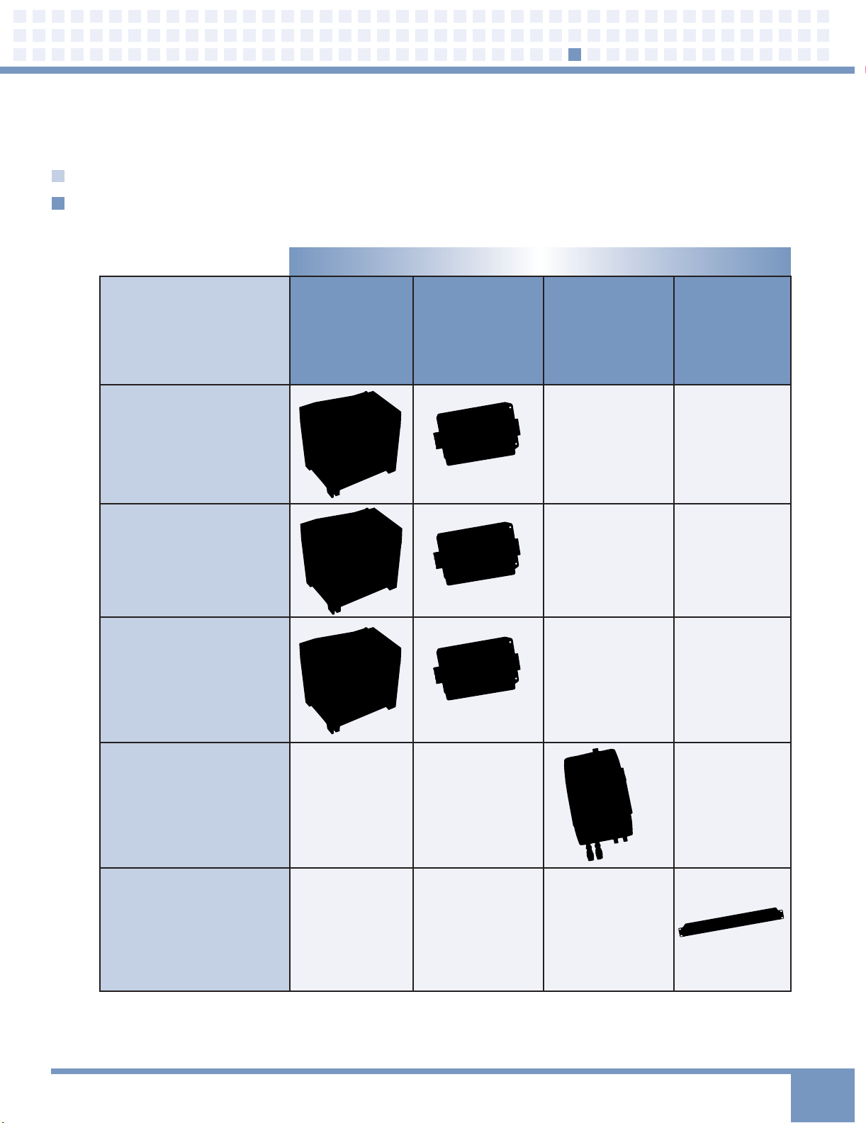
TVSS/SPDs — Product Selection Guide
Find your application in the left column.
Then look across for the appropriate product (s).
PRODUCTS
APPLICATIONS

DRS12031 DRS23031 DRS27731 DRS34631
Electrical
Characteristics
System Voltage 120/208, 230/400, 220/380, 277/480, 346/600 VAC
127/220 VAC 240/415 VAC 254/440 VAC
Type of Network TT-TN TT-TN TT-TN TT-TN
Modes of Protection L-N; N-PE L-N; N-PE L-N; N-PE L-N; N-PE
Nominal Voltage Un–120 V Un–230 V Un–277 V Un–346 V
Rated Voltage Uc–150 V Uc–320 V Uc–320 V Uc–420 V
(MCOV)
Nominal Discharge 1n–20 kA 1n–20 kA 1n–20 kA 1n–20 kA
Current (8 x 20 µs)
Maximum Imax–40 kA Imax–40 kA Imax–40 kA Imax–40 kA
Discharge Current
Voltage Protection Up–1.2 kV Up–1.6 kV Up—1.6 kV Up–2.0 kV
Level
Response Time TS–25 ns TS–25 ns TS–25 ns TS–25 ns
Relative Humidity 95% 95% 95% 95%
Isolation
Resistance > 103 MV > 103 MV > 103 MV > 103 MV
Test Standards
EN 61643-11 Type 2
IEC61643- 1:1998-02 Class II
Mechanical
Characteristics
Dimensions (Length x Width x Height) 70.8mm x 90.5mm x 68mm
I/O Connections By Screw Terminal: 4-25 mm
2
By Connection Bus
MOV Encapsulation Material Epoxy Resin
Disconnection Indicator Mechanical Indicator
Status Monitoring Remote Alarm Terminals
Mounting Symmetrical Rail (EN50022/DIN46277-3)
Operation Temperature Range -40°C to +85°C
Degree of Protection IP 20
Disconnection Device Thermal Cutoff System
Housing Material ABS/PA UL94V0
Performance Technical Specifications
TVSS/Surge Protective Devices (SPDs)
3
Nominal Voltage # of Metal Oxide Varistor Modules*
(Un) (XXX) (X)
120 0
230 1
240 2
277 3
346 4
480
# of Gas Tube Modules** Higher Rated Voltage***
(X) (Optional)
0Q
1
How to Specify the Appropriate Model
*MOV modules are typically one module per phase and may be wired L-N, L-G or N-G.
**Gas Tube modules typically used in the N-G mode for type TT grounding systems.
***Certain applications require higher rated components in order to survive frequent
voltage rises, in this case order a unit with a “Q” at the end of the part number.
Replacement modules available: Order DRS + U
n
+ M (for MOV) or G (for Gas Tube)
Features
■ Effectivel y ha ndles high- energy tran sients
on T T, TN- C, T N-S and TN -C-S three-pha se
power systems
■ SPD rat ed Type 2 in acco rdan ce w ith
EN 61643-11; Clas s I & II in accord ance
wi th I EC 6 1643-1
■ Bui lt-i n th erma l co mponen ts disco nnect
SPD from the powe r so urce to av oid
thermal runaw ay con ditions
■ MOV onl y or MOV +Gas Tube models
availab le
■ Fast res ponse time , hi gh surge cur rent
capability, low vol tage prote cti on l evel s
■ Vis ual insp ect ion wind ow on ea ch module
indicates status
■ 3-p ole term inal provi des remo te s tatus
monitoring
■ DIN rail mounti ng and plug -in module
design allow fo r ea sy i nstallat ion,
maint enan ce a nd rep lace ment of
su rge elem ent
■ 5 yea r wa rrant y
DRS Series
The DRS is a modular surge protective device (SPD) that is designed for easy
installation in control panels using standard DIN rail mounting brackets. The DRS
devices offer both normal and common surge protection up to 40 kA per phase.
Example: DRS 120 3 1 Q

General Technical Specifications
Features
■ Fast res ponse ti me
■ 40, 000 Amps p er pha se c apacit y
■ Fail safe and fus ed
■ Ope rati onal status indicato rs
■ UL 1449 Third Edi tion, Typ e 2 listed
■ 5 y ear warran ty
Edco EMC-240B
120/240 VAC Low Exposure AC Panel Protection
The Edco EMC-240B surge suppressor is designed to protect AC distribution
panel circuits or 120V power supplies feeding sensitive electronic equipment.
Electrically, the unit incorporates MOV and thermal fusing technology. The Edco
EMC 240B is designed to be installed in parallel on standard single phase
120VAC (L,N,G) circuits.
Edco™FAS-120AC
120 VAC Medium Exposure AC Panel Protection
The Edco FAS-120AC surge suppressor is designed to protect AC panel
circuits or 120V power supplies feeding sensitive electronic equipment.
Electrically the unit incorporates MOV and thermal fusing technology. This device is
designed to be installed in parallel on standard single phase 120VAC (L,N,G) circuits.
Installation can be close-nipple up to a distribution panel/circuit or hardwired
in parallel up to power supply input terminal screws. Be sure to dress leads as
short as possible.
Operating Voltage 120 VAC
VPR L-N:700V, L-G:700V, N-G:700V
UL Location Type 2
I-Nominal 3 kA
Operating Current NA, Parallel
Total Peak Surge Current 15.5 kA (8 x 20 µs)
Operating Frequency 47-63 Hz
EMI Attenuation (100 kHz to 100 MHz) > 25 dB
SPD Technology Metal Oxide Varistors (MOVs)
Modes of Protection Line-to-Neutral,
Line-to-Ground, Neutral-to-Ground
Status Indication Power On & MOV Functional
Connection Type Wire Leads
Operating Temperature -40°C to +85°C
Dimensions (Inches) 2.5H x 1.5W x 3.0L
Weight 4.2 oz
Certifications ANSI/UL 1449 Third Edition
Features
■ LED indicat or
■ Fast res ponse ti me
■ The rmal fus e
■ L-G, L-N, & N- G pr otec tio n
■ Com pact size
■ Liq uid tight co nduit fitting
■ 5 y ear warran ty
General Technical Specifications
TVSS/Surge Protective Devices (SPDs)
4
Operating Voltage 120/240 VAC
VPR L-N:600V, L-L:1,200V
Fault Current Rating 42 kAIC
UL Location Type 2
I-Nominal (kA) 3kA
Operating Current NA, Parallel
Total Peak Surge Current 80 kA (8 x 20 µs)
Operating Frequency 47-63 Hz
EMI Attenuation (100 kHz to 100 MHz) > 40 dB
SPD Technology Metal Oxide Varistors (MOVs)
Modes of Protection Line-to-Line,
Line-to-Neutral
Status Indication Power On & MOVs functional
Connection Type Wire Leads
Operating Temperature -40°C to +85°C
Dimensions (Inches) 4.6H x 2.2W x 2.8L
Weight 13.5 oz
Certifications ANSI/UL 1449 Third Edition
Type 2, CUL
Filtering/Line Conditioning
5
APPLICATIONS
Islatrol
™
IE
Series
Islatrol
™
IC+/LRIC+
Series
Islatrol
™
SP-6TVN
Series
Islatrol
™
RM
Series
Programmable Logic
Controllers
*
Control Panels
(AC Power)
* *
Various OEM
Equipment
* *
Home
Entertainment/Office
*
AC Rack Equipment
PRODUCTS
Filtering/Line Conditioning — Product Selection Guide
Find your application in the left column.
Then look across for the appropriate product.

Model L-N L-G N-G L-L
IE-103
IE-105
IE-110
IE-120
IE-203
IE-205
IE-210
IE-220
Peak Surge Current Capability (8 x 20 µs)
Line to Neutral 15,000 Amps
Line to Ground 15,000 Amps
Neutral to Ground 15,000 Amps
Total 45,000 Amps
Frequency Response (Forward-Reverse)
Normal Mode 100 kHz to 50 MHz - 90 dB Min
Common Mode 5 MHz to 50 MHz - 60 dB Min
Typical Category A Ringwave (6 kV, 200 A, 100 kHz)
Normal Mode/Common Mode
3 Amp 1 V/300 V
5 Amp 0.7 V/292 V
10 Amp 0.7 V/300 V
20 Amp 0.7 V/300 V
Typical Category B Ringwave (6 kV, 500 A, 100 kHz)
Normal Mode/Common Mode
3 Amp 178 V/300 V
5 Amp 162 V/291 V
10 Amp 153 V/300 V
20 Amp 200 V/300 V
MCOV
120 Volt 150 VRMS
240 Volt 275 VRMS
Line Frequency 47 - 63 Hz
Connection Terminal
Mounting Type DIN/Flange
Weight < 3 lbs
Response Time
Normal Mode < 0.5 ns
Common Mode < 5 ns
Operating Temperature -40°C to +45°C
Derate Linearly to 60% at +70ºC
Operating Humidity 0% to 95%
Voltage* Continuous Current Model
120 V 3 Amps IE-103
120 V 5 Amps IE-105
120 V 10 Amps IE-110
120 V 20 Amps IE-120
Voltage* Continuous Current Model
240 V 3 Amps IE-203
240 V 5 Amps IE-205
240 V 10 Amps IE-210
240 V 20 Amps IE-220
* All voltage configurations are single phase - 2 wire + gnd.
Islatrol™IE Series
Active Tracking Filter
™
The Islatrol™IE is a series-connected DIN or flange mounted high-
frequency noise filter and surge suppressor. Its ideal applications include
critical industrial loads drawing up to 20 Amps of continuous current,
while t ypical applications include any microprocessor-based products,
including industrial PLCs, OEM applications, and motion control systems.
Features
■ Mul ti- stag ed design, com bining a unique
hybrid cl amping net wor k with the ac tive
tracking techno logy of the Isla trol
®
family
■ Surge current capac ity — 45,000 Amps
■ Tran sien t pr otec tio n in all modes: line
to neut ral, line to groun d, and neutral
to ground
■ LED status indicati on and for m C co ntact
for rem ote indicati on
■ DIN mount able enc losure
■ ANSI/UL 1449 Third Edi tion Type 4,
1283, CUL recog nize d, CE
■ 10 ye ar w arranty
Dimensional Diagram
Performance Technical Specifications
General Technical Specifications
Ordering Information
Filtering/Line Conditioning
6
400V 600V 600V N/A
400V 600V 500V N/A
1,000V 700V
900V 700V
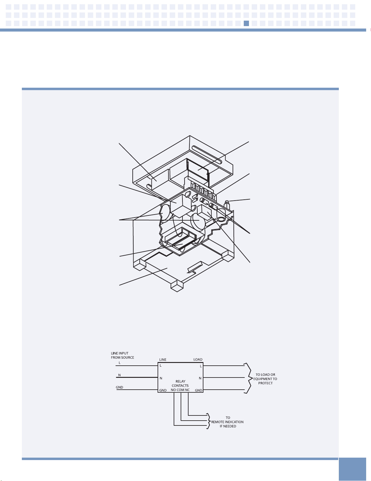
Islatrol™IE Series
Active Tracking Filter
™
Shunt Absorbing Components
load side sine wave tracking circuitry
Form C Relay Contacts
normally open and normally closed dry
contact for remote status monitoring
MOV Array
high-energy surge current diversion
array providing transient protection
line to neutral, line to ground, and
neutral to ground
Series Blocking Inductor
voltage blocking current
soothing inductor
DIN Rail Mountable
mounts to standard 35 mm
industrial DIN rail; rotates 90°
for mounting flexibility
Shunt Absorbing Components
line side sine wave tracking circuitry
Unit Status Indicator
green LED monitors the operational
status of the Elite Series
Finger Safe Terminals
IEC 998 approved terminals
Silicon Avalanche Diodes
fast responding surge current
diversion components
Pulse Capacitor
high-frequency noise absorption
System Design
Connection Diagram
Filtering/Line Conditioning
7

MCOV
120 Volt 150 VRMS
240 Volt 275 VRMS
Line Frequency 47 - 63 Hz
Response Time
Normal Mode < 0.5 ns
Common Mode < 5 ns
Operating Temperature
-40°C to +45°C at Full Load
Derate Linearly to 60% at +70ºC
Operating Humidity 0% to 95%
Peak Surge Current Capability (8 x 20 µs)
Line to Neutral 15,000 Amps
Line to Ground 15,000 Amps
Neutral to Ground 15,000 Amps
Load Surge Current Rating
10 mSec 5 x Nominal
1 sec 3 x Nominal
10 sec 2 x Nominal
Packaging
• High Impact Plastic Case
• Vacuum Impregnated Magnetics
• Epoxy Encapsulated
Frequency Response (Forward-Reverse)
Normal Mode 100 kHz to 50 MHz - 90 dB Min
Common Mode 5 MHz to 50 MHz - 60 dB Min
Typical Category A Ringwave (6 kV, 200 A, 100 kHz)
Model Normal Common
IC+102 / LRIC+102 1.0 / 0.9 302 / 287
IC+105 / LRIC+105 0.7 / 0.8 292 / 307
IC+107 / LRIC+107 0.7 / 0.7 302 / 293
IC+115 / LRIC+115 0.7 / 0.7 304 / 306
IC+130 / IC+202 0.5 / 1.1 306 / 536
IC+205 / IC+207 1.5 / 0.8 628 / 616
IC+215 / IC+230 0.6 / 0.9 572 / 566
Typical Category B Ringwave (6 kV, 500 A, 100 kHz)
Model Normal Common
IC+102 / LRIC+102 178 / 188 302 / 285
IC+105 / LRIC+105 162 / 191 291 / 300
IC+107 / LRIC+107 173 / 190 300 / 298
IC+115 / LRIC+115 153 / 149 307 / 309
IC+130 / IC+202 241 / 302 299 / 532
IC+205 / IC+207 378 / 336 594 / 596
IC+215 / IC+230 272 / 342 548 / 578
Series Blocking Inductors
voltage blocking current
smoothing inductors
Shunt Absorbing Components
sine wave tracking circuitry
MOV Transient Protection
high-energy transient
protection line to neutral,
line to ground,
neutral to ground
Pulse Capacitor
high-frequency noise absorption
Islatrol™IC+/LRIC+ Series
Active Tracking Filter
™
Series connected high-frequency noise filter with transient protection. Offers
the flexibility of either receptacle/line cord connection or hard-wired connection
to critical loads (up to 30 Amperes). Applications include industrial or office
equipment, computers placed in harsh environments.
Features
■ Typi cally reduces normal m ode transien ts
to +/-2 vol ts
■ Sur ge cur rent capacit y — 45,000 Amps
■ Tran sien t pr otec tio n in all modes: line
to neut ral, line to groun d, and neutral
to ground
■ LED power ind ication
■ UL 1283, CSA reco gnized
■ 10 year war ranty
Note: All measurements in volts. IEEE test results with
no AC applied. Normal mode—L1-N or L1-L2;
Common mode—L-G, N-G or L1-G, L2-G.
System Design
Connection Diagram
Filtering/Line Conditioning
TM
TM
8

Filtering/Line Conditioning
9
Islatrol™IC+/LRIC+ Series
Active Tracking Filter
™
120 VAC Models with barrier strip at input and output/with wire leads at input and output (WL)
Rated Case Mounting Flange
Output Dimensions (In) Dimensions (In) Screw Weight
Model (Amps) A x B x C D x E x F x G Size (lbs)
IC+102 / IC+102WL 2.5 4 x 2.88 x 1.81 4.38 x 2.12 x 5.31 x 0.19 #6 1.0
IC+105 / IC+105WL 5.0 4 x 2.88 x 1.81 4.38 x 2.12 x 5.31 x 0.19 #6 1.3
IC+107 / IC+107WL 7.5 4.75 x 4.75 x 2.35 5.25 x 3.50 x 6.25 x 0.19 #6 2.0
IC+115 / IC+115WL 15 6.25 x 4.75 x 2.35 6.75 x 3.50 x 7.75 x 0.19 #8 3.5
IC+130 / IC+130WL 30 7.75 x 4.75 x 2.35 8.25 x 3.50 x 9.00 x 0.19 #8 6.0
120 VAC Models with 5 foot line cord and single NEMA 5-15 receptacle
Rated Case Mounting Flange
Output Dimensions (In) Dimensions (In) Screw Weight
Model (Amps) A x B x C D x E x F x G Size (lbs)
LRIC+102 2.5 4.5 x 3.0 x 1.88 N/A N/A 1.3
LRIC+105 5.0 4.5 x 4.5 x 2.38 N/A N/A 2.0
LRIC+107 7.5 6.0 x 4.5 x 2.38 N/A N/A 2.3
LRIC+115 15 7.5 x 4.5 x 2.38 N/A N/A 4.0
240 VAC Models with barrier strip at input and output/with wire leads at input and output (WL)
Rated Case Mounting Flange
Output Dimensions (In) Dimensions (In) Screw Weight
Model (Amps) A x B x C D x E x F x G Size (lbs)
IC+202 / IC+202WL 2.5 4 x 2.88 x 1.81 4.38 x 2.12 x 5.31 x 0.19 #6 1.3
IC+205 / IC+205WL 5.0 4.75 x 4.75 x 2.35 5.25 x 3.50 x 6.25 x 0.19 #6 2.0
IC+207 / IC+207WL 7.5 6.25 x 4.75 x 2.35 6.75 x 3.50 x 7.75 x 0.19 #8 3.3
IC+215 / IC+215WL 15 7.75 x 4.75 x 2.35 8.25 x 3.50 x 9.00 x 0.19 #8 5.8
IC+230 / IC+230WL 30 7.75 x 4.75 x 2.35 8.25 x 3.50 x 9.00 x 0.19 #8 6.0
Ordering Information
Dimensional Diagram
F
B
C
G
A
D
E
MOUNTING
DIMENSIONS
Islatrol™Active Tracking Filters™carry a 10 year warranty
F
B
C
G
A
D
E
MOUNTING
DIMENSIONS

Features
■ Plu gs i nto sta ndar d 12 0 V, 15 Amp
elec tric al outlet
■ Tota l pe ak s urge current cap acit y o f
39,000 Amps
■ Cab les fo r te leph one, video, and
data co nnect ions
■ Reposi tionable o utlets rot ate to
accommoda te a vail able spa ce
■ Per fec t fo r ti ght spac es, behi nd furniture
and appliance s
■ Int elli gent mon itoring against improper
wiring/grounding
■ 60 dB max imum high frequenc y
■ Ope rati onal indicator lamp
■ 5 y ear limite d warrant y
AC Power Protection
VPR L-N:330V, L-G:400V, N-G:400V
Nominal Operating Voltage 120 VAC, Single Phase
Operating Voltage Range 120 VAC +/- 10%
Operating Frequency Range 47 — 63 Hz
Rated Output (Amps) 15 Amperes
ANSI/IEEE C62.41 Category Category A & B
Connection Type (6) 5-15R Receptacles and
5-15P Plug
Phase Configuration 2 Wire + Gnd
Size 7.5 x 4.75 x 1.75 (Inches)
Enclosure High Impact Plastic
Weight 2.0 lbs (0.9 kgs)
Modes Of Protection L — N, L — G, N — G
Indication of Suppression Status Status Indicator
Response Time < .5 ns Normal Mode
Certifications ANSI/UL 1449 Third Edition Type 3
Warranty 5 Year
Maximum Continuous Operating Voltage (MCOV)
Line to Neutral 130 VAC
Peak Surge Current (8 x 20 ms)
Line to Neutral 13,000 Amps
Line to Ground 13,000 Amps
Neutral to Ground 13,000 Amps
Total 39,000 Amps
ANSI/IEEE C62.41 Cat A Ringwave (6 kV, 200 A, 100 kHz)
Normal Mode 265 V
Common Mode 290 V
ANSI/IEEE C62.41 Cat B Ringwave (6 kV, 500 A, 100 kHz)
Normal Mode 275 V
Common Mode 290 V
Frequency Response
Normal Mode 60 dB Maximum, forward/reverse, 100 kHz to 50 MHz
Common Mode 40 dB Maximum, forward/reverse, 5 MHz to 50 MHz
Low Voltage Protection
Video 1 & 2 Phone Network
Connection Type Type “F” Type RJ-11 Type RJ-45
Cables Provided 6' (2x) Type “F” 6' RJ-11 Male 6' RJ-45 Male
6' Ends 6' Ends Ends
Peak Surge Current 5 kA 2 kA 3 kA
(8 x 20 µs) (10 x 1000 µs) (8 x 20 µs)
Capacitance <12 pf <50 pf <70 pf
Protection Level L-G T-R, T-G, R-G L-G (8 Lines)
Clamping Voltage (DC) 145 V 270-350 V 30 V
Attenuation 1 dB @ 2 Ghz N/A N/A
General Technical Specifications
Islatrol™— SP-6TVN
Industrial Strength Surge Suppression (Series)
The Islatrol™SP-6TVN plug-in unit is an Active Tracking Filter™which plugs into
a standard duplex receptacle. It features uniquely designed repositionable
outlets for easy installation behind desks and other furniture. It protects
sensitive home or office equipment from damaging power disturbances
traveling through wiring to electrical outlets.
Filtering/Line Conditioning
Repositionable Outlets
-WK EY
10

Filtering/Line Conditioning
11
Islatrol™— RM Series
120 VAC Rackmount
Islatrol™RM Series AC rackmount surge protector is ideal for protecting the
power feeding valuable rack equipment. Status LEDs indicate the correct power
is coming to the unit, whether the unit is properly grounded and whether the
surge components are still intact. Units are available with a digital meter,
mounted on the front of the unit, which will monitor the voltage, current and
power of the protected equipment.
Features
■ 40 kA surge prote cti on
■ 60 dB max noise filteri ng
■ 15 & 20 A model s avai lable
■ Power, grou nd and surge statu s indica tors
■ Dig ital meter
■ Opt iona l t wist lock plug
■ 1 y ear warran ty
Model shown: RM-115-10 RM
General Technical Specifications
Model Voltage Amperage Plug (NEMA) Receptacles (NEMA) Digital Meter Locking Plug
RM-115-10RM 120 V 15 A 5-15P 5-15R Yes No
RM-120-10RM 120 V 20 A 5-20P 5-20R Yes No
Rackmount AC Power Protection
ANSI/UL 1449 Third Edition
VPR L-N:400 V, L-G:500V, N-G:400V
Rated Voltage 120 V
Rated Current 15 A & 20 A
Peak Surge Current 20 kA/mode, 40 kA/phase
Response Time <5 ns
EMI/RFI Filtering 60 dB Max
LED Indicators Green-Power on
Green-Ground OK
Green-Surge Circuit OK
Digital Meter Voltage Amps, Watts, VA, Hz, PF,
(Optional) Kwh, and Clock
Input Power
15 A Models SJT 14/3C Power Cord (9 ft)
with NEMA 5-15P Plug
20A Models SJT 12/3C Power Cord (9 ft)
with NEMA 5-20P Plug
NEMA L5-20P Plug- Optional
Output Receptacles
15A Models Front- (2) NEMA 5-15R
Back- (10) NEMA 5-15R
20A Models Front- (2) NEMA 5-20R
Back- (10) NEMA 5-20R
Thermal Protection Thermal Protected MOVs
Overcurrent Protection Circuit
Dimensions 1.75"H x 19"W x 3.8"D (1U)
Certifications ANSI/UL 1449 Third Edition Type 3
Warranty 1 Year

APPLICATIONS
Edco
™
DRS
Series
Edco
™
PC642
Series
Edco
™
PHC
Series
Edco
™
RJA/RJD
Series
Edco
™
RM-CAT6
Series
Edco
™
SLAC
Series
Edco
™
SS64/65
Series
Edco
™
CX
Series
Edco
™
RM-CX06
Series
Transmitters
Telephone
Industrial
Communications
Signaling
Circuits
Programmable
Logic Controllers
(I/O) Circuits
Control Panels
(Low Voltage)
Communication
Rack Equipment
Video Equipment
Video Rack
Equipment
Water/
Wastewater
Instrumentation
Data/Signal Line Protection
12
Data/Signal Line Protection — Product Selection Guide
Find your application in the left column.
Then look across for the appropriate product.
PRODUCTS

Data/Signal Line Protection
13
Edco™DRS (DC) Series
DIN Rail Protection
The Edco™DRS (DC) Series is a DIN rail mountable, single-pair surge suppression
module implementing three-stage hybrid technology. This module addresses
over-voltage transients with gas tubes and silicon avalanche components. In
addition, sneak currents are mitigated with resettable fuses (PTCs). The PTCs
increase resistance several orders of magnitude when over-currents exceed
safe levels. A normal state resumes when over-currents are removed. The ability
to self-restore in this manner significantly increases suppressor performance
and survivability.
The Edco
™
DRS (DC) Series mounts onto a standard 35 mm industrial DIN rail. There
are three “Field Side” and three “Electronics Side” screw terminals. One is reserved
for a shield. Three electrically tied ground terminals are provided for grounding the
Edco™DRS Series unit to Building-Approved Ground. Shield is isolated from ground.
For a 2-terminal version without a shield, order the Edco™DRS-XXX-2.
Features
■ Low-vo lta ge d ata surge prot ect ion
■ Three-stage hybrid prote ction
■ Sneak/ fault curren t pr otec tio n with
resettable fuse s — PTCs
■ Low profile pa ckaging
■ UL 497B listed
■ Easy installat ion
■ F its standard 35 mm DIN rail
■ Fast resp onse time
< 1 nanos econd
■ 5 year warrant y
**Warning!! DRS-130RMS is for Discrete Signal
Use Only. Do not use DRS-130RMS on 120
VAC Power Lines. This unit is a non-hybrid,
MOV design, rated above 5 A operational
current and can withstand greater than eight
occurrences of a 10 kA 8 x 20 µs waveform, and
greater than 1000 occurrences of a 200 A 10 x
1000 µs waveform.
Dimensional Diagrams
General Technical Specifications
Maximum Nominal Surge Peak Current Typ Maximum Nominal
Part Peak Signal Breakdown 1p 10 x 1000 µs 8 x 20 µs Cap Continuous Series
Number Voltage Voltage Current Waveform (pf) Current (ma) Resistance
DRS-036 30 36 >100 10 kA 1500 150 5 Ohms
**DRS-130 170 200 >10 8 kA 1500 5000 None
DRS-XXX DRS-XXX-2
(2 terminal version)

Maximum Continuous 5-250 VDC
Operating Voltage (MCOV)
Clamping Voltage 8-300 VDC
Operating Current 150mA
Peak Surge Current 10 kA (8 x 20 µs)
Frequency Range 0 to 20 MHz
Insertion Loss < 0.1 dB at 20 MHz
SPD Technology GDT, SAD, w/Series PTC
Connection Type Terminal block
w/compression lugs
Terminals accept up to 10 AWG
Operating Temperature -40°C to +85°C
Dimensions (Inches) 2H x 1W x 2.5L
(PC642 + Mounting Base)
Weight 1 oz
Certifications UL 497B
Caution: The hybrid design of this product includes
series resistance. Do not place this product in
service on any signal line capable of supplying
more than 150 milliamperes continuously.
Features
■ Thr ee-stage hybri d protec tio n
■ Sne ak/f ault cur rent prote cti on
■ Resettable fus ing — PTCs
■ Low cap acit ance opt ion
■ Plu g-i n mo dule
■ Fast res ponse time
■ Req uire s Ed co
™
PCB1B- WKE Y base
■ PC6 42PTU (Pas s Thru Unit)
availab le for troubleshoo ting
■ 5 y ear warran ty
Edco™PC642 Series
Zone/Loop/Data
The Edco™PC642 Series surge suppressor is a two-pair (four-wire) module
implementing three-stage hybrid technology. This module addresses
over-voltage transients with gas tubes and silicon avalanche components. In
addition, sneak and fault currents are mitigated with resettable fuses (PTCs).
The PTCs increase resistance several orders of magnitude when over-currents
exceed safe levels. A normal state resumes when over-currents are removed.
The ability to self-restore in this manner significantly increases suppressor
performance and survivability.
The Edco
™
PC642 card edge module is gold-plated, double-sided, and is
designed to mate with the Edco™ PCB1B-WKEY gold-plated female terminal
connector. When snapped together, the data circuits “pass thru” the protector
in a serial fashion from the four “Field Side” terminals to the four “Electronics
Side” terminals. Terminals 1 or 10 of the Edco™PCB1B-WKEY must be attached
to Building-Approved Ground per Edco™Technical Bulletin # 2015.
-WKEY
DO NOT daisy chain grounds.
NOT intended for shield termination.
Install ground in accordance with
all applicable codes.
PC642C-
LC
D
Low Capacitance,
Line to Line, Line to Ground
008, 036, 043 models
only
008, 043 models only
Line to Line protection only
Line to Ground
200 models only
008
036
043
200
Max Operating
Voltage
Clamping
Voltage
(1000V@1mA)
5 VDC
30 VDC
36 VDC
43-250 VDC
8 VDC
36 VDC
43 VDC
300 VDC
APPLICATION:
RS485, RS422: PC642C-008LC
RS423, Token Ring: PC642C-008LC
RS232: PC642C-036LC
E-NET, 10 BASE T: PC642C-030LC-036LC
4–20ma: PC642C-036LC
24 VAC Power PC642C-043LC
General Technical Specifications
Terminal Assignments
Ordering Information
EDCO PCB1B-WKEY BASE SOLD SEPARATELY
How to Specify the Appropriate Model
Data/Signal Line Protection
14
-WKEY

Edco™PHC Series
Two-Pair Signaling Circuit Protector (Modular)
The Edco™PHC Series is designed to protect two pairs of wires specifically for
alarm and security systems where operating currents can be as high as 5 Amps.
Electrically, the Edco™PHC Series is a rugged series hybrid implementing a
staged complement of MOVs, copper wound inductors and Silicon Avalanche
Diodes. This design reduces series resistance to 0.2 Ohms per pair. These
products are intended to mate with an Edco PCB1B-WKEY gold-plated female
terminal connector.
The Edco
™
PHC modules plug into a base assembly (Edco™PCB1B-WKEY). The
base assembly can be mounted to any flat surface and should be located as close
as practical to the protected equipment. Terminal 1 and/or terminal 10 should
be connected to Building-Approved Ground with 12 or 10 gauge solid wire.
Features
■ Thr ee-stage prote cti on
■ Dif ferential prote cti on
■ Com mon mo de prote cti on
■ Plu g-i n mo dule
■ Aut omat ic r ecov ery
■ Fast res ponse time
■ Con tinu ous curren t up to 5 Amps
■ UL 497B listed
■ Req uire s Ed co
™
PCB1B- WKE Y base
■ PC6 42PTU (Pas s Thru Unit)
availab le for troubleshooti ng
■ 5 y ear warran ty
Operating Voltage 36-70 VDC
Clamping Voltage 43-100 VDC
Operating Current 5 A
Peak Surge Current 10 kA (8 x 20 µs)
Frequency Range 0 to 10 MHz
Insertion Loss < 0.1 dB at 10 MHz
SPD Technology MOV, SAD, w/Series Inductor
Connection Type Terminal block
w/compression lugs
Terminals accept up to 10 AWG
Operating Temperature -40°C to +85°C
Dimensions (Inches) 3.7H x 1.75W x 2.375L
(PHC + Mounting Base)
Weight 8 oz
Certifications UL 497B
24V Horn, Strobe, Bell: PHC-043 & PCB1B-WKEY
70V Speaker Lines: PHC-SP70 & PCB1B-WKEY
-WK EY
General Technical Specifications
Dimensions
Terminal Assignments
Ordering Information
EDCO PCB1B-WKEY BASE SOLD SEPARATELY
Applications Part Number
DO NOT daisy chain grounds. NOT intended for shield
termination. Install ground in accordance with all
applicable codes.
How to Specify the Appropriate Model
Data/Signal Line Protection
15
-WKEY
-WK EY

F
B
C
G
A
D
E
MOUNTING
DIMENSIONS
F
B
C
G
A
D
E
MOUNTING
DIMENSIONS
Features
■ <1 nano seco nd respo nse time
■ Sol id- stat e rese ttable fus es-PTCs
■ Sil icon break over te chnology
■ Low cap acit ance
■ Lin e-to- line prote cti on
■ Tip and ring to groun d protec tio n
■ CAN/CS A C2 2.2, No. 22 6-92 Complia nt
■ UL 497A listed
■ 4 p air prot ect ion
■ 5 y ear warran ty
Edco™RJA-RJD Series
RJ-45 Telephone/Data
The Edco™RJA and Edco™RJD Series are four pair telephone/data line
protectors that implement advanced two stage hybrid design. These units
address over-voltage transients with silicon breakover devices, while sneak
and fault currents are mitigated with PTC technology, which consists of solid
state resettable fuses.
The Edco
™
RJA and Edco™RJD Series incorporate RJ-45 female jacks in and out.
The Edco™RJA voltage clamp is set for C.O. Trunks and Analog Telephone
Extensions (with ring in voltage), and the Edco™RJD voltage clamp is set for
Digital Extensions (no ring in voltage).
Operating Voltage 48, 220 VDC
Clamping Voltage 55, 280 VDC
Operating Current 0.15 A
Peak Surge Current 200 A (10 x 1000 µs)
Frequency Range 0 to 50 MHz
Insertion Loss < 0.1 dB at 50 MHz
SPD Technology Silicon Breakover
Devices w/Series PTC
Connection Type RJ-45 Jacks
Operating Temperature -40°C to +85°C
Dimensions (Inches) 1.0H x 2.5W x 4.25L
Weight 3 oz
Certifications UL 497A, CUL,
Analog Phone RJA-45
Digital Phone RJD-45
General Technical Specifications
Ordering Information
Installation
The Edco™RJA and Edco
™
RJD Series are intended
for indoor use only
and shall be employed
on the equipment side of
a listed primary
telephone protector.
Data/Signal Line Protection
16

Operating Voltage 130 VDC
Clamping Voltage 150 VDC
(DC Spark Over Voltage)
Operating Current 1 A
Peak Surge Current 10 kA (8 x 20 µs)
Maximum Power 10 Watts
Impedence 50 Ohms
Frequency Range 0 to 4 GHz
Insertion Loss < 0.3 dB to 0.5 dB 2 to 3 GHz
SPD Technology Gas Discharge Tube (GDT)
Connection Type Female N-Type
Operating Temperature -30°C to +85°C
Dimensions (Inches) 1.25H x .875W x 2.5L
Weight 4 oz
CX-HFN-FF (Female–Female)
CX-HFN-FM (Female-Male)
General Technical Specifications
Data/Signal Line Protection
17
Edco™RM-CAT6-POE Series
CAT6-POE Channel Rackmount
The Edco™RM-CAT6-POE Series is a multi-channel high-speed data line protector
that utilizes a three-stage hybrid design technology. This unit addresses high-
energy voltage transients that can damage expensive computer equipment. Ideal
for network switches and hubs, the Edco™RM-CAT6-POE Series is easily mounted
in close proximity to the protected equipment.
Operating Voltage 57 V
Clamping Voltage 68 V
Transmission Speed 10 Mbps,
100 Mbps, 1,000 Mbps
Operating Current 0.15 A
Connection Means 2-Port Series
SPD Technology GDT, SAD, W/Series PTC
Modes of Protection Signal High-Low,
Signal High-Ground,
Signal Low-Ground
Peak Surge Current 10 kA (8 x 20 µs)
Insertion Loss <0.1 dB
VSWR <1.2
Operating Humidity 0-95% Non-Condensing
Operating Temperature -40°C to +85°C
Input Connection Type RJ-45
Output Connection Type RJ-45
Mounting Rackmount
Enclosure Type Painted Steel
Dimensions 1.75Hx19Wx6.3D
Weight 5.5 lbs
Warranty 1 Year
RM-CAT6-8POE 8 Channels
RM-CAT6-16POE 16 Channels
RM-CAT6-24POE 24 Channels
RM-CAT6-48POE 48 Channels
Features
■ Exceeds cate gor y 6 transmission values
■ Com pact 1U rack size
■ Mee ts Pow er-Over- Ethern et (POE)
requirement s
■ Low ins ert ion loss
■ Thr ee stage hybrid
■ 1 y ear warran ty
■ Replac eabl e su rge modules
■ Up to 48 ch annels ava ilable
General Technical Specifications
Edco™CX-HFN Series
High Frequency Coax Protector — N-Type
The Edco™CX-HFN surge protectors are designed to protect sensitive electronic
equipment from damage due to excessive voltage or currents generated by
lightning or static build-up.
The Edco
™
CX-HFN offers low signal loss at frequencies up to 4 gigahertz. The unit
also has a replaceable protection cartridge (CX-RC). The Edco™CX-HFN
accommodates both bulkhead mount and stud mount. The input and output
connections are interchangeable.
Features
■ Low sig nal lo ss
■ 5 y ear warranty
Ordering Information
Ordering Information

Data/Signal Line Protection
18
Technology Three-Stage Series Hybrid
Input Voltage 120 VAC 50/60 Hz
Output Current 15 Amps Max.
Response Time <5 Nanoseconds
Maximum Surge Current (8x20 µs) 10 kA
Occurrences at 500 Amps >50
Parameter Normal Mode Common Mode
(L-N) (L-G) (N-G)
IEEE 587 CAT A Ring* 172 V 280 V
IEEE 587 CAT B Ring* 205 V 280 V
IEEE 587 CAT B Impulse* 330 V 360 V
*Measured from zero volts, 90° Phase angle
Signal Protector Technology GDT, PTC, SAD
AC Protector Technology MOV, Fuse
Peak Surge Current 10 kA
Response Time <1 Nanosecond
Voltage Clamp (customer selected) 8–200 Volts
Series Resistance 5 ! (Typical)
NEMA-4X
Glass-Filled Polycarbonate Base
Cover Molded in Clear Polycarbonate
Knockouts for 1/2" and 3/4" hubs
Bosses for 6 BZ x 3/8" Self-Tapping Screws
Maximum Protection—Total Insulation
Corrosion Resistant
Resists Temperature of 248°F
Flammability Rating UL94-5V
Nominal Outside dimensions (Inches)
H= 6.89, W=6.89, D=2.95
Edco™SLAC Series
AC Power/Signal
The Edco™SLAC Series suppressor is specifically designed to protect electronic
instruments used by the water/wastewater industries. It combines hybrid AC
power protection and signal line protection in a NEMA-4X polycarbonate case.
The AC power suppressor can supply up to 1875 Watts and has a 15 Amp
replaceable fuse to prevent overloading of the protective elements. A “Power
ON” LED provides visual indication that power is applied to instruments. Signal
line protection is accomplished by the Edco™PC642 Series available in a variety
of voltage clamps. Signal current can be monitored by reading the voltage
across the 10 V, 1% resistors (TP1 & TP2 or TP3 & TP4). All leads going to the
Edco™SLAC board are terminated by quick disconnect or barrier block
connectors to facilitate easy removal for service or replacement.
Features
■ Opt iona l t wist lock plug lightning & surge
suppression f or AC powe r an d low-voltage
signal lines
■ Ser ies hybr id AC suppressor /filter
■ Plu g-i n pr otec tio n mo dule
■ 15 Amp repl aceable fuse
■ Test jac ks for signa l line monitoring
■ “Po wer ON” indicato r
■ Opt iona l stainless stee l or fiber glass
enclo sure
■ 5 y ear warran ty
■ ANSI/UL 1449 Third Edi tion
General Technical Specifications
AC Power
General Technical Specifications
Signal Line
Standard Enclosure Optional Enclosure
Ordering Information
How to Specify the Appropriate Model
These blocks are for PC642
VoltageSelection if applicable. See
PC 642 Datasheet for additional
information. 0 3 6 L C is standard
for 4-20 mA Signal Line.

Edco™SS64 & SS65 Series
Wastewater/Industrial Applications
The Edco™SS64 and Edco™SS65 Series suppressors are designed for the water
and wastewater industry. These multi-stage hybrid suppressors address
over-voltage transients with gas tube and silicon avalanche technology. In
addition, sneak and fault currents are mitigated with PTC devices which
consist of solid-state resettable fuses. The units are encapsulated in stainless
steel pipe nipples making them suitable for use in severe environments. The
Edco™SS64 models protect a signal pair and the Edco™SS65 models protect a
signal pair plus the cable shield (drain wire).
Features
■ Tran sien t pr otec tio n fo r
low- volt age signal lines
■ Sne ak/f ault cur rent prote cti on
■ Res etta ble fusi ng—PTC s
■ Dif ferential and com mon mode prote cti on
■ Aut omat ic recover y
■ Enc apsula ted in st ainl ess steel
pipe nipples
■ Pro tection fo r one pair
(Two w ires & shiel d on SS6 5)
■ 5 yea r wa rrant y
Response Time < 1 Nanosecond
Maximum Signal Voltage 28 V Max
DC Clamping Level (L-G) 36 V ±l0%
DC Clamping Level (L-L) 72 V ±l0%
Maximum let-thru Voltage:
Line-to-Ground (10x700 µs) 44 V @ 400 A
Maximum let-thru Voltage:
Line-to-Line (10x700 µs) 90 V @ 400 A
Series Resistance (per conductor) 5 V (typical)
Capacitance:
(Zero Volts Bias) (L-L) 600 pf typical
(L-G) 1200 pf typical
Number of Occurrences 400 @ 500 Amps
(10x1000 µs)
General Technical Specifications Typical Applications
Caution: The hybrid design of this product includes series resistance. Do not place this product
in service on any signal lines capable of supplying more than 150 milliamperes continuously.
Data/Signal Line Protection
19

Edco™CX Series
CCTV & Data Applications/Coax
The Edco™CX06-M & Edco™CX06-MI Surge Protective Devices (SPDs)
implement three-stage hybrid technology. The SPDs address over-voltage
transients with a primary Gas Discharge Tube (GDT), and secondary Silicon
Avalanche Diode (SAD) components. Over-current protection, e.g. sneak and
fault currents, are mitigated with solid-state resettable fuses — PTCs. The Edco
™
CX06-M & Edco™CX06-MI SPDs are designed in accordance with NFPA 780
(2004 edition) requirements, with up to 20 kA of surge current capability. The
Edco™CX06-MI model has an isolated ground and is recommended for use at the
camera end.
Features
■ Sneak /fault current prote cti on
■ Low inser tio n loss
■ Shiel ded case
■ CX0 6-MI has an is olated ground
■ 5 yea r wa rrant y
Operating Voltage 5 VDC
Clamping Voltage 6 VDC
Operating Current 0.15 A
Peak Surge Current 20 kA (8 x 20 µs)
Frequency Range 0 to 20MHz
Insertion Loss < 0.1 dB at 20 MHz
SPD Technology GDT, SAD, w/Series PTC
Connection Type BNC, 50/75 Ohm
Operating Temperature -40°C to +85°C
Dimensions (Inches) M = 1.5H x 1W x 3.25L
MI = 1.5H x 1W x 4L
Weight M = 2.3 oz MI = 3 oz
Certifications UL 497B
Head End CX06-M
Camera End CX06-MI
Camera End CX06-MI-SBL
General Technical Specifications
Ordering Information
Edco™RM-CX06-16R
Channel Rackmount
The Edco™RM-CX06-16R Surge Protective Device (SPD) is a 16 channel coax
SPD implementing three-stage hybrid technology. The SPD addresses over-
voltage transients with a primary Gas Discharge Tube (GDT), and secondary
Silicon Avalanche Diode (SAD) components. Over-current protection, e.g.,
sneak and fault currents, are mitigated with new solid-state resettable fuses —
PTCs. The Edco™RM-CX06-16R SPD is designed in accordance with NFPA 780
(2004 edition) requirements, with up to 20 kA of surge current capability.
Features
■ Sne ak/f ault cur rent prote cti on
■ Low ins ert ion loss
■ Shi elde d case
■ 16 chan nel
■ 1 y ear warran ty
Operating Voltage 5 VDC
Clamping Voltage 6 VDC
Operating Current 0.15 A
Peak Surge Current 20 kA (8 x 20 µs)
Frequency Range 0 to 100 MHz
Insertion Loss < 0.1 dB at 20 MHz
SPD Technology GDT, SAD, w/Series PTC
Connection Type BNC, 50/75 Ohm
Operating Temperature -40°C to +85°C
Dimensions (Inches) 1.75H x 19W x 2.0D (1U)
Weight 3.2 lbs
Certifications UL 497B
General Technical Specifications
Data/Signal Line Protection
20

Data/Signal Line Protection
21
Edco™CAT6-5POE Series
CAT6/CAT5 Power Over Ethernet
The Edco™CAT6-5POE Series is designed to work on Category 5 Power-Over-
Ethernet transmission lines as well as Category 6 applications. Ideal to protect
expensive equipment against surges and transients entering a building on
exposed transmission lines.
Features
■ Exc eeds CAT 5 & 6 transmission values
■ CAT 5 PO E comp atible
■ CAT 6 co mpat ible
■ App licati ons up to 60 VDC @ 300 m A
■ 1 yea r wa rrant y
Operating Voltage 60 VDC
Clamping Voltage 65 VDC
Operating Current 300 mA
Peak Surge Current 60A (10 x 1000 µs)
Frequency Range 0 to 250 MHz
Insertion Loss < 0.1 dB at 20 MHz
SPD Technology Silicon Avalanche Diode (SAD)
Connection Type RJ-45 Jacks
Operating Temperature -40°C to +85°C
Dimensions (Inches) 0.8H x 1.0W x 2.3L
Weight 1 oz
RJ-45 (Female-Female) CAT6-5POE-FF
General Technical Specifications
Ordering Information

Technical Bulletins — High-Density Multiple Input Rack
NOTES:
1. SLAC UNIT PROVIDES ONE POWER AND TWO SIGNAL PROTECTION CIRCUITS.
2. SURGE DEVICES SHOULD BE GROUNDED LOCALLY WITH A GROUND ROD,
AND ALSO AT THE MAIN PANEL ELECTRICAL GROUND.
3. CHECK WITH EMERSON NETWORK POWER SURGE PROTECTION, INC. TO
DETERMINE IF OUTPUT CAN BE SURGE PROTECTED.
Technical Bulletins
22
TM
TM
TM
TM
TM

Technical Bulletins — Surge Protection for the Water Industry
NOTES:
1. SLAC UNIT PROVIDES ONE POWER AND TWO SIGNAL PROTECTION CIRCUITS.
2. SURGE DEVICES SHOULD BE GROUNDED LOCALLY WITH A GROUND ROD,
AND ALSO AT THE MAIN PANEL ELECTRICAL GROUND.
3. CHECK WITH EMERSON NETWORK POWER SURGE PROTECTION, INC. TO
DETERMINE IF OUTPUT CAN BE SURGE PROTECTED.
Technical Bulletins
23
TM
TM
TM
TM
TM

Technical Bulletins — Surge Protection for Power and Signal Lines
NOTES:
1. SLAC UNIT PROVIDES ONE POWER AND TWO SIGNAL PROTECTION CIRCUITS.
2. SURGE DEVICES SHOULD BE GROUNDED LOCALLY WITH A GROUND ROD,
AND ALSO AT THE MAIN PANEL ELECTRICAL GROUND.
3. CHECK WITH EMERSON NETWORK POWER SURGE PROTECTION, INC. TO
DETERMINE IF OUTPUT CAN BE SURGE PROTECTED.
24
TM
TM
TM
TM


Business-Critical Continuity, Emerson Network Power and the Emerson Network Power logo are trademarks and service marks of Emerson Electric Co.
©2014 Emerson Electric Co.
While every precaution has been taken to ensure accuracy and completeness in this literature, Emerson Network Power assumes no responsibility, and disclaims all liability
for damages resulting from use of this information or for any errors or omissions.
SL-30900 Rev.3 1/14 Printed in USA
Emerson Network Power.
The global leader in enabling Business-Critical Continuity
TM
.
AC Power
Connectivity
DC Power
Embedded Computing
Embedded Power
Industrial Power
Infrastructure Management & Monitoring
Outside Plant
Power Switching & Controls
EmersonNetworkPower. com/surge
Thermal Management
Racks & Integrated Cabinents
Service
Contact
Surge Protection
100 Emerson Parkway
Binghamton, NY 13905
T: 607-721-8840 (Outside U.S.)
T: 800-288-6169 (U.S. & Canada Only)
F: 607-722-8713
E: SurgeTech@Emerson.com
 Loading...