

Page 1

Application Guidelines
PeC Solution Overview for
Commercial Comfort Applications
Page 2

AGL_Sol_PEC_02_E_Rev01
About these guidelines ................................................................................................ 1
1 Safety instructions ............................................................................................ 1
1.1 Icon explanation ................................................................................................................. 1
1.2 Safety statements .............................................................................................................. 1
1.3 General warnings ............................................................................................................... 2
1.4 Use with flammable refrigerants ........................................................................................ 2
1.5 General recommendations................................................................................................. 2
1.6 Communication with Application Engineering and Development teams ........................... 3
2 Product description .......................................................................................... 4
2.1 General information about the Emerson PeC controller .................................................... 4
2.2 Refrigerants ....................................................................................................................... 4
2.3 Available PeC configurations ............................................................................................. 5
2.4 Main components and parts .............................................................................................. 5
2.4.1 Supported compressor range ................................................................................. 5
2.4.2 Supported variable speed drive ............................................................................. 6
2.4.3 PeC accessories .................................................................................................... 6
2.4.4 Supported electronic expansion valve range ......................................................... 6
2.4.5 Supported pressure transmitters ............................................................................ 6
2.4.6 Supported temperature sensors ............................................................................. 6
2.5 PeC system functionalities ................................................................................................. 7
2.6 System configuration ......................................................................................................... 7
3 Hardware configuration .................................................................................... 8
3.1 PeC Hardware configuration options ................................................................................. 8
3.2 Examples of application ..................................................................................................... 9
3.2.1 Monoblock air-to-water chiller system scheme with variable-speed & fixed-speed
compressors and 1 electronic expansion valve .................................................................. 9
3.2.2 Monoblock air-to-water reversible heat pump system scheme with variable-
speed & fixed-speed compressors and 1 electronic expansion valve .............................. 11
3.3 DLT sensor installation .................................................................................................... 12
4 OEM control strategy on PeC ......................................................................... 13
4.1 System controller with Modbus communication............................................................... 13
4.2 OEM capacity demand strategy ....................................................................................... 14
4.3 System controller with analog 0-10 V demand signal + 1 digital signal........................... 14
5 PeC functionalities .......................................................................................... 15
5.1 State machine matrix ....................................................................................................... 15
5.2 Functionalities .................................................................................................................. 16
5.2.1 Smart compressor operating map management .................................................. 16
5.2.2 DLT limitation control function with wet suction control ....................................... 17
5.2.3 Main superheat control ......................................................................................... 17
5.2.4 External capacity request via Modbus ................................................................. 17
Page 3

AGL_Sol_PEC_02_E_Rev01
5.2.5 Start-up configuration function ............................................................................. 17
5.2.6 Compressor shutdown ......................................................................................... 17
5.2.7 Oil return function ................................................................................................. 17
5.2.8 Maximum speed during heating ........................................................................... 17
5.2.9 Speed control ....................................................................................................... 17
5.2.10 Envelope limitations ............................................................................................. 18
5.2.11 Variable-speed Scroll smart crankcase heater function ....................................... 18
5.2.12 FREMAR band protection (FREquency Management to Avoid Resonances) ..... 18
5.3 Alarm management .......................................................................................................... 18
5.3.1 "Alarm State" during compressor operation ......................................................... 18
5.3.2 Hardware alarms .................................................................................................. 19
5.3.3 Software alarms ................................................................................................... 19
5.3.4 Machine alarms summary .................................................................................... 20
5.4 Energy metering ............................................................................................................... 20
5.5 Modbus protocol specifications ........................................................................................ 21
6 Laboratory testing ........................................................................................... 22
6.1 Semi-manual mode .......................................................................................................... 22
6.2 Manual mode ................................................................................................................... 22
6.3 Starting lab testing with Modmonitoring software ............................................................ 22
6.4 Software update on the PeC ............................................................................................ 22
7 Electrical connection ...................................................................................... 23
7.1 General recommendations............................................................................................... 23
7.1.1 EMC ...................................................................................................................... 24
7.1.2 Ferrites ................................................................................................................. 24
7.1.3 Digital inputs and outputs wiring .......................................................................... 25
8 Items list for electronic solution package ..................................................... 26
9 Certification & approval .................................................................................. 27
10 Dismantling & disposal ................................................................................... 27
DISCLAIMER ............................................................................................................... 27
Page 4
AGL_Sol_PEC_02_E_Rev01 1
About these guidelines
The purpose of these guidelines is to provide guidance in the application of the Emerson PeC
controller in users’ systems. They are intended to answer the questions raised while designing,
assembling, starting and operating a system with this product.
Besides the support they provide, the instructions listed herein are also critical for the proper and
safe functioning of the system. The performance and reliability of the system may be impacted if
the product is not used according to these guidelines or is misused.
These guidelines cover stationary applications only. For mobile applications, please contact the
Application Engineering department at Emerson as other considerations may apply.
1 Safety instructions
Emerson PeC controllers are manufactured according to the latest European safety standards.
Particular emphasis has been placed on the user’s safety.
The PeC controllers are intended for installation in systems in accordance with the European
Machinery Directive MD 2006/42/EC, the Low Voltage Directive LVD 2014/35/EU and the
Electromagnetic Compatibility Directive EMC 2014/30/EU. They may be put to service only if they
have been installed in these systems according to instructions and conform to the corresponding
provisions of legislation. For relevant standards please refer to the Manufacturer’s Declaration,
available on request or at www.climate.emerson.com/en-gb.
These guidelines form part of the product and must always be kept near the controller for easy and
quick reference. They should be retained throughout the lifetime of the controller.
You are strongly advised to follow these safety instructions.
1.1 Icon explanation
WARNING
This icon alerts the user of important
instructions to avoid personal injury and
material damage.
CAUTION
This icon alerts the user of instructions
to avoid property damage and possible
personal injury.
WARNING
High voltage!
This icon alerts the user of non-insulated
"dangerous voltage" within the product
area that is sufficiently high to constitute a
risk of electric shock to persons.
IMPORTANT
This icon alerts the user of important
operating and maintenance or
assistance instructions.
Danger of explosive atmosphere
This icon indicates a risk of explosive
atmosphere.
NOTE
This word indicates a recommendation
for easier operation.
1.2 Safety statements
▪ This product can only be used for purposes specified by the manufacturer.
▪ This product is designed to be used in HVAC/R systems and can only be installed,
operated or maintained by qualified electrical personnel with additional system-related
expertise. Please immediately contact the manufacturer for support if the user is
uncertain with any safety-related issue.
▪ Electrical connections must be made by qualified electrical personnel with additional
system-related expertise.
▪ All valid standards and local electrical regulations for connecting electrical and
refrigeration equipment must be observed.
▪ The national legislation and regulations regarding personnel protection must be
observed.
Use personal safety equipment. Safety goggles, gloves,
protective clothing, safety boots and hard hats should be worn
where necessary.
Page 5
2 AGL_Sol_PEC_02_E_Rev01
1.3 General warnings
WARNING
Conductor cables! Electrical shock hazard! This product operates at
hazardous voltages which can cause severe personal injury or equipment
damage. Extreme care and precautions must be taken when handling the
product. Electrical connections must be made by qualified electrical
personnel.
Use a grounded system only. Moulded electrical plugs must be used in all
applications. Refer to original equipment wiring diagrams.
Do not operate system before all cable connections are completed.
Disconnect all voltages from system before installation or service. Allow drive
components to electrically discharge for a minimum of two minutes before
servicing.
WARNING
Conductor cables! Electrical shock hazard! The controller must always be
inserted inside an electrical panel that can only be accessed by authorised
personnel. The keyboard must be the only part that can be reached. The
device must never be hand-held while being used.
CAUTION
The controller cannot be used as a safety device. Verify the limits of
application before using the device.
IMPORTANT
Transit damage! Controller disfunction! Use original packaging.
1.4 Use with flammable refrigerants
WARNING
The PeC controller is not designed or qualified based on the ATEX directive!
The PeC controller fulfils the requirements of the mentioned system standard
with the usage of flammable refrigerants.
Usage with flammable refrigerants is limited to systems which are based on the IEC 60335-2-40
standard. For systems using flammable refrigerants A2L and A3 the following points must be
considered:
▪ The controller mounting area must be in Zone 2 or outside any ATEX zone and in line with
"Pollution Degree 2" classification.
▪ No airstream guided over the electronics.
▪ No condensation under normal operation.
▪ The IP class of the controller mounting area must be in line with the system standard.
1.5 General recommendations
The customer shall bear full responsibility and risk for product configuration in order to achieve the
results pertaining to installation and/or final equipment/system. Upon customer's request and
following a specific agreement, Emerson. may be present during the start-up of the final
machine/application, as a consultant. However, under no circumstances can Emerson be held
responsible for the correct operation of the final equipment/system.
Since Emerson products form part of a very high level of technology, a qualification/configuration/
programming/commissioning stage is required to use them as best as possible. Otherwise, these
products may malfunction, and Emerson cannot be held responsible.
It is good practice to bear the following in mind for all Emerson products:
▪ Prevent the electronic circuits from getting wet as contact made with water, humidity or any
other type of liquid can damage them. Comply with the temperature and humidity limits
specified in the guidelines in order to store the product correctly.
▪ The device must not be installed in particularly hot environments as high temperatures can
cause damage, eg, to electronic circuits and/or plastic components forming part of the casing.
Page 6

AGL_Sol_PEC_02_E_Rev01 3
Comply with the temperature and humidity limits specified in the guidelines in order to store the
product correctly.
▪ Under no circumstances is the device to be opened – the user does not require the internal
components. Please contact qualified service personnel for any assistance.
▪ Prevent the device from being dropped, knocked or shaken as either can cause irreparable
damage.
▪ Do not clean the device with corrosive chemical products, solvents or aggressive detergents.
▪ The device must not be used in applications that differ from those specified in these guidelines.
1.6 Communication with Application Engineering and Development teams
When communicating with Application Engineering and/or development teams at Emerson during
the development and testing phases of programs using the PeC, please include:
1. log file
2. description file
3. configuration file
These will help them give you more precise and complete answers to your questions.
Page 7
4 AGL_Sol_PEC_02_E_Rev01
2 Product description
2.1 General information about the Emerson PeC controller
The PeC (Performance Controller) controller has been specifically developed for Copeland™ scroll
compressors using R410A and R32 refrigerants in heating and cooling applications such as
reversible heat pumps, in both air-to-water and brine-to-water configurations.
PeC was developed to run and protect the refrigerant cycle with low control effort for the system
controller but also to provide detailed information around the refrigerant cycle.
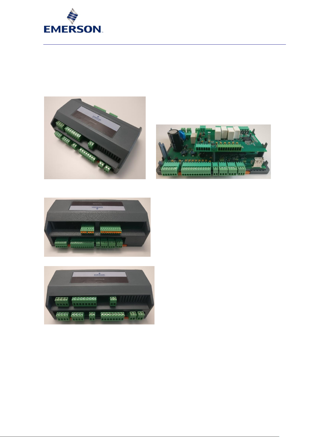
Figure 1: PeC external view Figure 2: Internal view
The external dimensions of the PeC controller are 185 x 130 x 60 mm.
Figure 3: Top side view
Figure 4: Bottom side view
2.2 Refrigerants
The PeC controller operates with refrigerant systems using:
▪ R410A
▪ R32
Page 8
AGL_Sol_PEC_02_E_Rev01 5
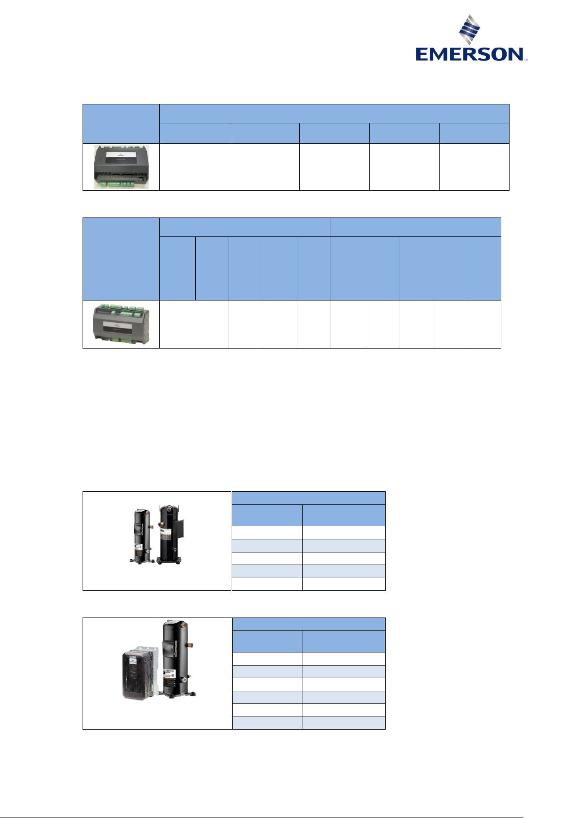
2.3 Available PeC configurations
The following tables show the hardware and software capabilities with PeC C100 and C200.
PeC C100
Circuit 1
VS compressor
+ EV3 drive
Fixed speed
Temperature
probe min-max
Pressure
EXV
(bipolar)
1-3
(1 can be a variable speed)
5-7 2 1
Table 1
PeC C200
Circuit 1
Circuit 2
VS
compressor
+ EV3 drive
Fixed speed
Temperature
.probe
min-max
Pressure
EXV
(bipolar)
VS
compressor
+ EV3 drive
Fixed speed
Temperature
. Probe
min-max
Pressure
EXV
(bipolar)
1-3
(1 can be a
variable speed)
5-7 2 1 0 0-3
4-6 2 1
Table 2
NOTE: The PeC factory default is unconfigured (-1) so configuration is needed. Invalid or
unconfigured compressor package selection will cause an alarm.
2.4 Main components and parts
For components and parts ordering please contact the Application Engineering or Sales
Department at Emerson.
2.4.1 Supported compressor range
The PeC controller has been specifically developed for Copeland Scroll variable-speed
compressors using R410A and R32 refrigerants. It is currently qualified for the following ranges:
R32
Fixed-speed
compressor
Variable-speed
compressor
YP137
YPV066
YP154
YPV096
YP182
YP232
YP292
Table 3: Qualified compressors for use with R32
R410A
Fixed-speed
compressor
Variable-speed
compressor
ZP104
ZPV066
ZP122
ZPV096
ZP154
ZP182
ZP232
ZP292
Table 4: Qualified compressors for use with R410A
NOTE: Additional fixed-speed compressors may be supported based on customer request.
Page 9
6 AGL_Sol_PEC_02_E_Rev01
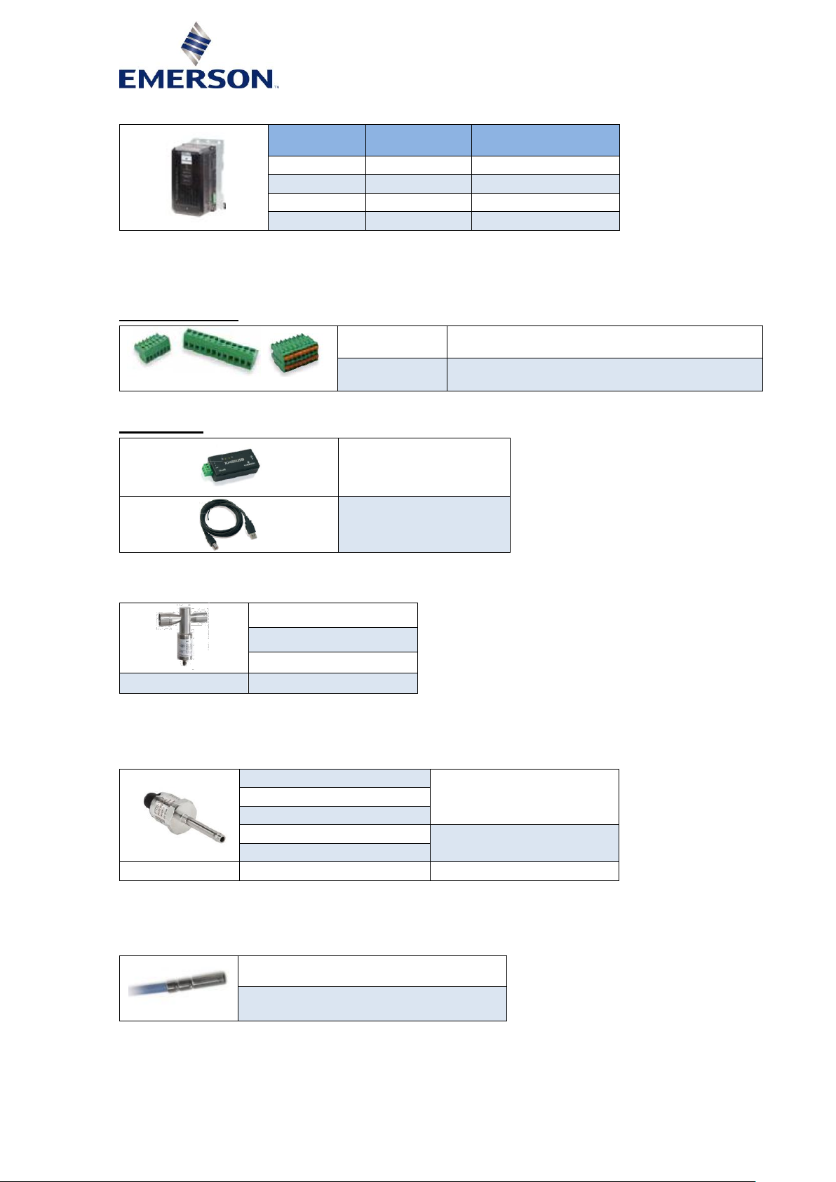
2.4.2 Supported variable speed drive
EV3150
EV3185
Compatible
compressor model
1 YPV066
1 ZPV066
1 YPV096
1 ZPV096
Table 5: Compatible compressor models
NOTE: The Emerson EV3 inverter drive is compliant with CAT 3 of EMC homologations.
2.4.3 PeC accessories
Plug-in connector
PeC C100
Screw terminals and/or cage clamp female
connectors
PeC C200
Screw terminals and/or cage clamp female
connectors
Table 6
USB adapter
XJ485-USB converter
Cable XJ485-USB
converter
Table 7
2.4.4 Supported electronic expansion valve range
Alco EX4
Alco EX5
Alco EX6
EXV-M30 (wires)
3.0 m
Table 8: Qualified expansion valves
NOTE: Additional expansion valves may be supported based on customer request.
2.4.5 Supported pressure transmitters
Alco PT5N-7 (7 bar max)
Low side
Alco PT5N-10 (10 bar max)
Alco PT5N-18 (18 bar max)
Alco PT5N-30 (30 bar max)
High side
Alco PT5N-50 (50 bar max)
Cable for PT5N
PT4-M30
3.0 m
Table 9: Qualified pressure transmitters
NOTE: Additional pressure transducers may be supported based on customer request.
2.4.6 Supported temperature sensors
TP1 series
100K (high temperature)
(for future use)
Table 10: Qualified temperature sensors
NOTE: Additional temperature sensors may be supported based on customer request.
Page 10
AGL_Sol_PEC_02_E_Rev01 7
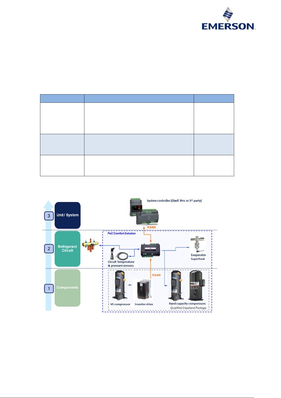
2.5 PeC system functionalities
The PeC controller controls and manages the refrigerant system comprising the Copeland Scroll
variable-speed compressor (ZPV066 or ZPV096 & YPV066 or YPV096), the drive, the electronic
expansion valves (EX range) and the 2- or 4-way valve. It is not a main system controller: it does
not control or manage the full unit (chiller / heat pump / others).
The OEM system controller and the PeC communicate via Modbus serial communication, in order
to exchange the fundamental parameters and information to provide an optimised combined control
of compressor and expansion devices for maximum performance and reliability.
Table 11 below gives an overview of the PeC features and benefits.
PeC
Features
Benefits
Smart
refrigerant circuit
management
▪ Variable speed & fixed speed
▪ Tandem/Trio capacity management
▪ Smart superheat control & EXV management
▪ Dynamic compressor operating maps
management
▪ Reverse cycle management
High efficiency &
reduced time-tomarket
Protection &
diagnostics
▪ Active compressor envelope protection
▪ Active floodback protection
▪ Oil recovery management
▪ Performance monitoring
Improved
protection &
increased
reliability
Communication
▪ RS485 Modbus OR analog interface
communication with system controller
▪ Pre-programmed Modbus communication with
CSD100 and alarms/parameters transfer
Modularity
Table 11
2.6 System configuration
Figure 5
Page 11
8 AGL_Sol_PEC_02_E_Rev01
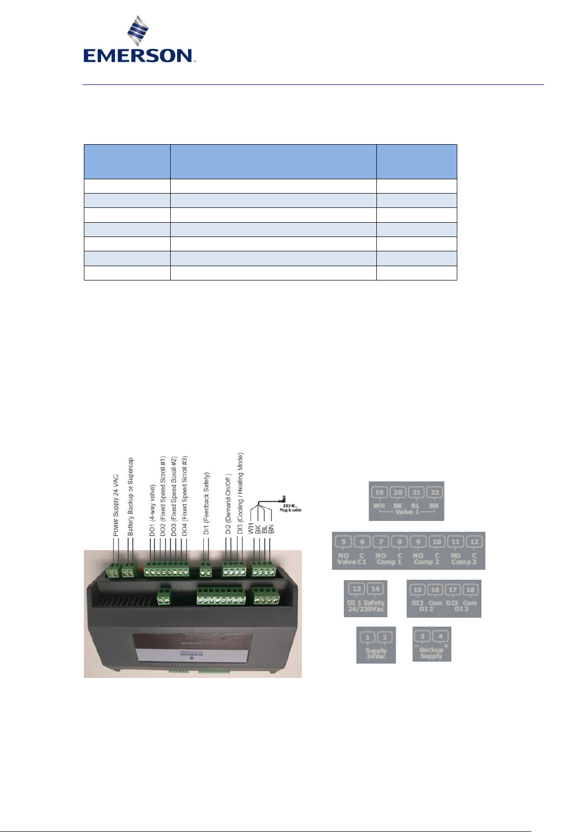
3 Hardware configuration
3.1 PeC Hardware configuration options
The controller board owns digital inputs and outputs that can provide customized use to the OEM.
Configuration can be set via Modbus using "Configuration Parameters".
Factory default
of digital inputs
& outputs
Description
Type
DI1
Input for high-pressure switch signal
Fixed function
DI2
Input for demand On/Off selection
Future use
DI3
Input for heating or cooling mode selection
Future use
DO1
Relay for switching 2 or 4-way valve
Fixed function
DO2
Relay for fixed-speed compressor start/stop
Fixed function
DO3
Relay for fixed-speed compressor start/stop
Fixed function
DO4
Relay for fixed-speed compressor start/stop
See below
Table 12
Configuration parameter options on DO1:
Register [94] if Defrost is enabled
0 = Cooling open circuit, heating closed circuit
1 = Cooling closed circuit, heating open circuit
Configuration parameter options on DO4:
Register [150] if compressors 1,3 installed (refer to index 86 bit 3) then relay can be used
to indicate PeC status
0 = Alarm negative logic (Alarm = Relay contact open)
1 = Alarm positive logic (Alarm = Relay contact closed)
2 = Drive active positive logic (speed <> = 0 relay closed)
Figure 6: PeC controller top side – Power supply, digital outputs & inputs & EXV connections
NOTE: For more information please refer to Application Guidelines AGL_Sol_PEC_01 "PeC
Solution Controllers for commercial Comfort Applications – PeC C100 & PeC C200" or
contact your local Application Engineering representative at Emerson.
Page 12

AGL_Sol_PEC_02_E_Rev01 9
3.2 Examples of application
3.2.1 Monoblock air-to-water chiller system scheme with variable-speed & fixed-speed
compressors and 1 electronic expansion valve
The schematic in Figure 7 shows an air-to-water chiller designed for cooling applications.
PeC controller
I/O
Type
Function
Comments
P1
PT5N-7-10-18
Suction pressure for
superheat (SH) control, high
SH protection and envelope
management
Configurable
Mandatory
P2
PT5N -30-50
Discharge pressure for
envelope management
Configurable
Mandatory
T1
TP1
Evaporator outlet gas
temperature for SH control
and high SH protection
Configurable
Optional
T2
TP1
Compressor suction gas
temperature for SH control
and high SH protection
Configurable
Mandatory
T3
TP1
Ambient temperature
Configurable
Mandatory
T4
TP1
Liquid temperature before
main EXV for energy counter
function & EXV management
Configurable
Mandatory
T5
TP1
Variable-speed compressor
discharge temperature
Configurable
Mandatory
T6
TP1
Fixed-speed compressor
discharge temperature
Configurable
Mandatory
T7
TP1
Fixed-speed compressor
discharge temperature
Configurable
Mandatory
24 VAC
Power supply
Fixed
24 VDC
Supercap XEC mono valve
Optional DO1
Relay
4-way
Fixed
Not needed
DO2
Relay
Fixed-speed compressor
command #1
Configurable
DO3
Relay
Fixed-speed compressor
command #2
Configurable
DO4
Relay
Fixed-speed compressor
command #3 ➔ indicates if
the drive is running or not
Configurable
DI1
Digital input
Feedback safety
Fixed
DI2
Digital input
Not used
State readable
by Modbus
Optional
DI3
Digital input
Not used
State readable
by Modbus
Optional
EXV/BIP
Stepper out -
bipolar
EXV control
Fixed An.In.
0-10 V analog
input
Not used
State readable
by Modbus
Optional
Bus Inverter
Modbus RS485
Communication with EV3
inverter
Fixed Bus Ctrl
Modbus RS485
Communication with system
controller
Fixed
Bus Slave
Modbus RS485
Modbus slave (may be used
for monitoring and/or
flashing)
Fixed
Table 13
Page 13

10 AGL_Sol_PEC_02_E_Rev01
Figure 7: Air-to-water chiller for cooling application
Figure 8: PeC C100 bottom side – Digital inputs, Modbus communication, pressure and temperature inputs
NOTE: For more information please refer to Application Guidelines AGL_Sol_PEC_01 "PeC
Solution Controllers for commercial Comfort Applications – PeC C100 & PeC C200" or
contact your local Application Engineering representative at Emerson.
Page 14

AGL_Sol_PEC_02_E_Rev01 11
3.2.2 Monoblock air-to-water reversible heat pump system scheme with variable-speed &
fixed-speed compressors and 1 electronic expansion valve
The schematic in Figure 9 shows an air-to-water reversible chiller/heat pump with the ability for
reverse cycling for defrost and heating modes. The main expansion valve, 4-way valve and
compressors are controlled by PeC.
PeC controller
I/O
Type
Function
Comments
P1
PT5N-7-1018
Suction pressure for
superheat (SH) control, high
SH protection and envelope
management
Configurable
Mandatory
P2
PT5N -30-50
Discharge pressure for
envelope management
Configurable
Mandatory
T1
TP1
Evaporator outlet gas
temperature for SH control
and high SH protection
Configurable
Optional
T2
TP1
Compressor suction gas
temperature for SH control
and high SH protection
Configurable
Mandatory
T3
TP1
Ambient temperature
Configurable
Mandatory
T4
TP1
Liquid temperature before
main EXV for energy counter
function & EXV management
Configurable
Mandatory
T5
TP1
Variable-speed compressor
discharge temperature
Configurable
Mandatory
T6
TP1
Fixed-speed compressor
discharge temperature
Configurable
Mandatory
T7
TP1
Fixed-speed compressor
discharge temperature
Configurable
Mandatory
P1
24 VAC
Power supply
Fixed P2
24 VDC
Supercap XEC mono valve
Optional DO1
Relay
4-way
Configurable
Not needed
DO2
Relay
Fixed-speed compressor
command #1
Fixed DO3
Relay
Fixed-speed compressor
command #2
Fixed
DO4
Relay
Fixed-speed compressor
command #3 ➔ indicates if
the drive is running or not
Configurable
DI1
Digital Input
Feedback safety
Fixed DI2
Digital Input
Not used
Fixed
Optional
DI3
Digital Input
Not used
Fixed
Optional
EXV/BIP
Stepper out -
bipolar
EXV control
Fixed An.In.
0-10 V analog
input
Not used
Fixed
Optional
Bus Inverter
Modbus RS485
Communication with EV3
inverter
Fixed Bus Ctrl
Modbus RS485
Communication with system
controller
Fixed
Bus Slave
Modbus RS485
Modbus slave (may be used
for monitoring and/or
flashing)
Fixed
Table 14
Page 15
12 AGL_Sol_PEC_02_E_Rev01
Figure 9: Air-to-water reversible chiller/heat pump
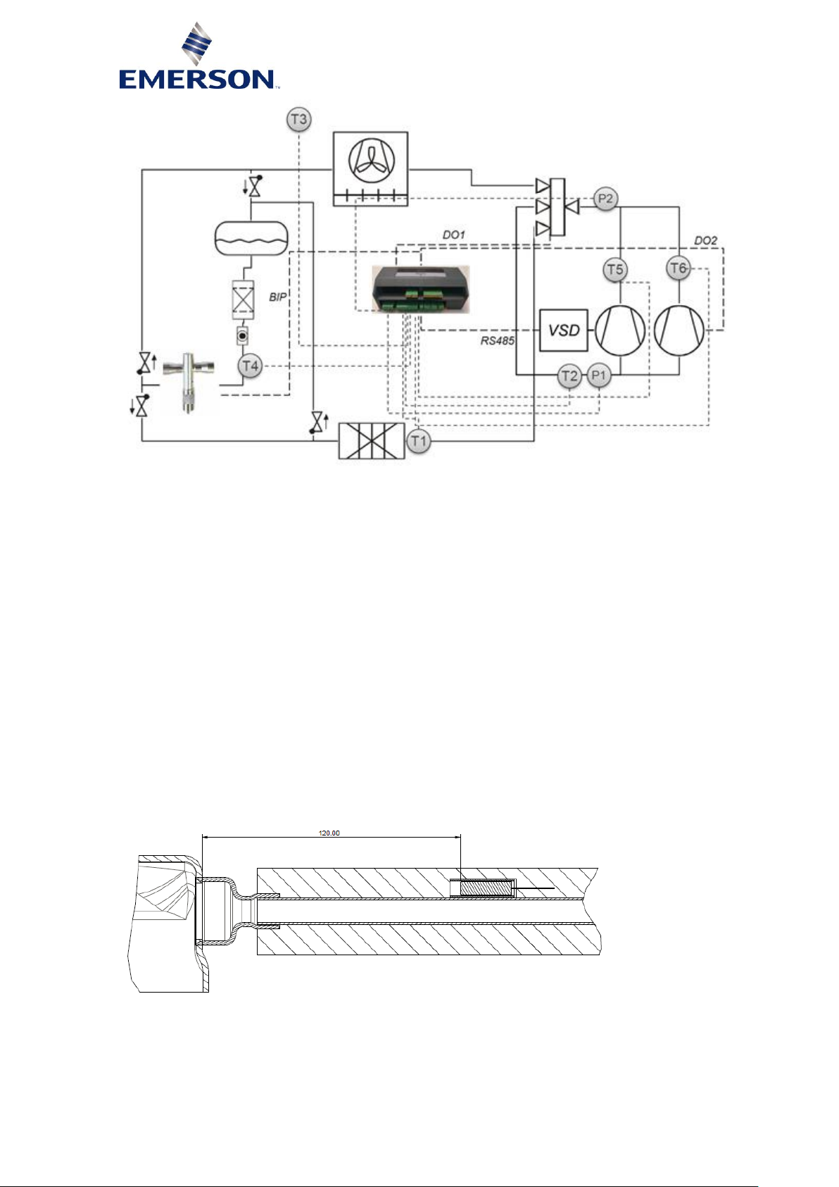
3.3 DLT sensor installation
The DLT sensor assembly improves the accuracy and response time of the temperature
management.
The high-pressure safety input was designed to fulfill the requirements of standard EN 378.
Please follow the recommendations below for sensor assembly:
▪ The temperature sensor has to be installed along the straight or bended pipe at a distance of
120 mm from the compressor shell.
▪ The discharge pipe including the sensor must be insulated to reduce the impact of ambient
temperature.
▪ Use thermal compound to improve heat transfer to the sensor. The thermal compound must be
approved for maximum system operating temperatures (usually 150 °C for R32).
▪ Protect the sensor from being moved or removed from its position by transport, vibration or any
other incident.
▪ The sensor must be installed in a copper sleeve to improve response time and to reduce setoff.
The copper sleeve must be brazed on the surface of the discharge pipe. Use thermal compound
to improve the heat transfer from the sleeve to the sensor.
Figure 10: Discharge temperature sensor mounting
Page 16

AGL_Sol_PEC_02_E_Rev01 13
4 OEM control strategy on PeC
4.1 System controller with Modbus communication
OEM system controller with Modbus RS485 RTU
System
controller
or separate
hardware
Bus
Digital I/O
↓ ↓ ↓
↑……↑
↑……↑
↓……↓
↓↑↑↑
Operating
mode
Heating/Cooling
Standby/Off
Capacity
Defrost
Start/Stop
Refrigerant cycle
info
Measured &
calculated values
Alarms and
warnings
Hardware &
software
Manual control
3 EXV’s & speed
& 2 relays
4/2-way valve
Digital
Switches/Input
↓ ↓ ↓
↑……↑
↑……↑
↓……↓
↓↑↑↑
Bus
Digital I/O
PeC
Table 15
The PeC was developed to run and protect the refrigerant cycle with low control effort for the
system controller but also to provide detailed information around the refrigerant cycle.
The system controller has to provide operating mode and capacity request to run the system.
▪ PeC operating modes can be Off, Heating, Cooling, Standby or Manual.
▪ Modbus communication also gives the possibility of enhanced use of all PeC functions shown
above.
▪ Accessories (pumps, fan, etc.) have to be controlled directly by the OEM controller to ensure
problem-free conditions for running the refrigerant cycle, eg, water flow on condenser around
compressor activity.
The OEM is responsible for developing a mitigation strategy in response to the occurrence of
alarms and warnings on the PeC.
There are different alarm conditions: "Alarm", "W arning" and "Alarm State".
Alarms and warnings may not lead to direct system shutdown. The system controller can monitor
these and take preventive action with the capacity request in order to avoid system shutdown by an
"Alarm State". The occurrence of an "Alarm State" will force immediate system shutdown.
When not acting on the PeC during an "Alarm State" phase, the PeC will recover, if possible, after
a recommended waiting phase (Alarm Pause).
The OEM has to consider the best response to specified alarms, eg, continue to activate the
system or let the system run, lock the system to protect it against damage, etc.
An advantage of Modbus communication is that it provides the full PeC functionality such as:
1) Operation control
▪ Gives precise control on operating mode and capacity request given %.
2) Monitoring all sensor values and system status
▪ Gives opportunity to use these data for OEM processing the system by the system
controller and for data logging. This provides valuable information to analyse the system
operation.
3) Explicit warning and alarm information
▪ The OEM controller can get explicit fault and warning information for preventive actions on
the system, as well for service and maintenance.
4) Manual control options
▪ For customized individual control strategy, the OEM controller can take control on the
compressor speed, the EXV’s and the 4-way valve instead of PeC internal control function.
5) Additional hardware functionality
▪ 1 Digital input + 2 potential free relays can be used by the system controller via Modbus or
internal pre-defined function.
Page 17

14 AGL_Sol_PEC_02_E_Rev01
4.2 OEM capacity demand strategy
The OEM controller should adapt the capacity demand signal to variable speed operation.
Common P, PI or PID control strategy should be used to avoid strong setpoint exceeding. This will
enhance the system efficiency and reduce useless high speeds, temperatures and sound on the
system. An optimal strategy has to be figured out via OEM system qualification process.
Figure 11
4.3 System controller with analog 0-10 V demand signal + 1 digital signal
Currently unused –Option available in future.
Page 18
AGL_Sol_PEC_02_E_Rev01 15
5 PeC functionalities
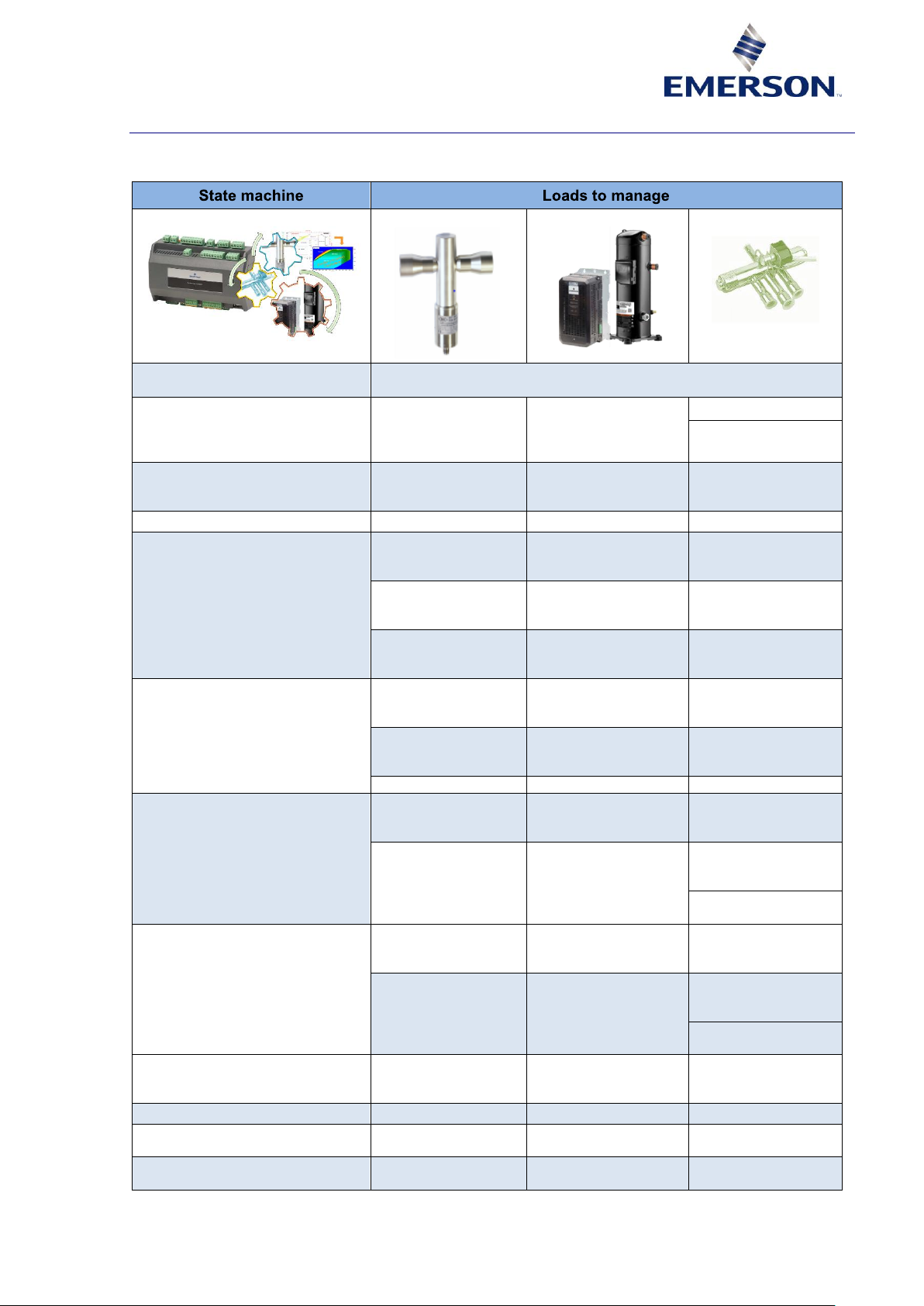
5.1 State machine matrix
EXV
Compressor pack
4-way valve
Off
After shutdown all valves are closed, the 4-way valve switches to cooling
position
Start-up
Normal start-up with
predefined opening
(function of ambient
temperature)
Normal start-up with
predefined speed and
duration
Swappable
Heating or cooling
active
Shutdown
Combination of
suction pressure and
compressor speed
The compressor speed
is reduced and the
valve is closing.
Standby
Stator heater
Cooling
Normal operation
(dynamic setpoint
graph)
Normal capacity
matching
Low superheat
operation (IPsensitive)
Exceptions
(protections,
prevention)
Floodback operation
Exceptions
(protections,
prevention)
Heating
Normal operation
(dynamic setpoint
graph)
Normal capacity
matching
Discharge
temperature
protection
Floodback operation
Transition to cooling / defrost
With unit stop: close
valves in relation with
capacity
With unit stop: shut
down all compressors
regularly
With unit stop: wait
for pressure band to
swap
Without unit stop:
proceed to cooling
start-up opening
Without unit stop: ramp
down to defined
capacity on each circuit
Without unit stop:
wait for defined
capacity to swap
Low delta pressure
protection
Transition to heating
With unit stop: close
valves in relation with
capacity
With unit stop: shut
down all compressors
regularly
With unit stop: wait
for pressure band to
swap
Without unit stop:
proceed to cooling
start-up opening
Without unit stop: ramp
down to defined
capacity on each circuit
Without unit stop:
wait for defined
capacity to swap
Low delta pressure
protection
Defrost
Suction pressure
regulation
Suction pressure
regulated capacity
band
Manual
Full manual mode
Full manual mode
Full manual mode
Emergency shutdown
Valve closing by
capacity
Fast capacity
shutdown
No action
Alarm
Valve closing by
capacity
Fast capacity
shutdown
No action
Table 16
Page 19

16 AGL_Sol_PEC_02_E_Rev01
The application is governed by a state machine of which the various states can be described as
follows:
▪ Off: The compressor shutdown procedure is executed. After shutdown, all valves are closed,
the 4-way valve switches to cooling position.
The stator heater function is active for both variable and fixed-speed scrolls.
▪ Shutdown: The compressor speed is reduced and the valve is closing.
▪ Standby: The compressor shutdown procedure is executed. After shutdown all valves are
closed and the 4-way valve switches to cooling position.
The stator heater function is active.
▪ Cooling: The compressor is running, the expansion valve is active and the 4-way valve is in
cooling position.
▪ Heating: The compressor is running, the expansion valve is active and the 4-way valve is in
heating position.
▪ Alarm: The unit has encountered a problem and stopped. When the PeC enters this state, it
shadows and clears the alarms. To avoid immediate restart, the unit is moved into waiting state
for a configurable amount of time.
▪ Transit cooling: The normal shutdown procedure is applied to switch off the compressors then
restart the system to cooling mode.
▪ Transit heating: The normal shutdown procedure is applied to switch off the compressors then
restart the system to heating mode.
▪ Defrost: The compressor is running, the expansion valve is active, the 4-way valve is in cooling
position.
▪ Waiting: The unit is in delayed restart after an alarm occurred during operating mode.
▪ Manual: The user takes control of every component individually.
▪ Compressor start: The unit has a heating request but the 4-way valve is in cooling mode, so
the unit starts in cooling mode to build up the necessary pressure to switch the 4-way valve.
Duration: 10 seconds at 2700 rpm.
5.2 Functionalities
5.2.1 Smart compressor operating map management
The operating envelopes of the variable-speed Scroll (VSS) are stored in the controller.
Based on measurements of suction and discharge pressures the possible speed range is
calculated for every operating point. Protection algorithms prevent the operating point to leave the
operating map by acting on compressor speed and expansion valve opening. Envelope alarm limits
are defined in order to avoid operation out of the envelope.
Additional fallback protection is implemented as safety software function in the drive. Torque and
discharge temperature limitation are the major protective features.
Figure 12
Page 20

AGL_Sol_PEC_02_E_Rev01 17
5.2.2 DLT limitation control function with wet suction control
The PeC will monitor the discharge line temperature. In case the high DLT area is entered,
superheat control will change into Discharge Temperature Protection control. The smart logic on
the EXV control ensures that the portion of liquid refrigerant droplets at the inlet of the compressor
is sufficient to keep the discharge line gas temperature below the allowed limit, while COP is kept
as good as possible, following the strategy "As much as needed and as little as possible".
The discharge gas temperature limitation is compressor-type dependent.
5.2.3 Main superheat control
One bipolar expansion valve per circuit can be controlled by PeC for heating and cooling mode.
The superheat control is based on pressure/temperature control strategy involving a self-adapting
PID control algorithm in order to adapt to different operating conditions. The main superheat
setpoint is being adapted in a pre-defined range in order to achieve stable and optimal operating
conditions.
NOTE: To test the control behaviour at special conditions, fixed and non-adaptive PID
parameters can be used in the "Manual Control mode". Please contact the Application
Engineering department at Emerson in case this functionality needs to be configured.
5.2.4 External capacity request via Modbus
The capacity request for heating and cooling modes can be sent by the system controller via
Modbus communication. In addition to the capacity, the operating mode has to be set separately.
The capacity input request, sent via Modbus communication, is an absolute value expressed in %.
The maximum available capacity for the current operating conditions is accessible by the system
controller via Modbus communication.
5.2.5 Start-up configuration function
During variable-speed compressor start-up, the compressor will run to the start-up speed with a
given ramp-up rate. When the 4-way valve position is correctly set, the compressor will go to the
mode-based start-up speed. The compressor speed is stabilized at the start-up speed for a given
time (start-up duration). After that, the controller will modulate the speed to meet the capacity
requirement of the system.
5.2.6 Compressor shutdown
If the controller receives a compressor shutdown command, it will switch off the fixed-speed
compressor(s) first if it is (they are) running. Then the variable-speed compressor will shut down
according to a pre-determined procedure.
5.2.7 Oil return function
To ensure sufficient oil level in the compressor at all times, the system has to be properly designed
and qualified by the OEM. To qualify oil return performance of the system, Emerson can provide
compressors with sight tubes.
All the parameters associated to the oil return function are configurable. If the compressor speed
goes below a threshold value for a certain amount of time, the oil return function triggers. This
function forces the compressor to an "oil return" speed for a brief period.
5.2.8 Maximum speed during heating
Maximum speed during heating restricts the speed of the compressor, to limit the load on it and the
heating capacity of the system.
5.2.9 Speed control
The speed regulation algorithm is used in heating and cooling modes. The PeC calculates the
speed that has to be applied to the compressor in order to match the requested capacity.
However, if the operating point reaches the lower limit of evaporating temperature, the compressor
speed is decreased in order to stay inside the envelope.
When the condensing temperature reaches the upper limit of the envelope, the speed is also
decreased.
Page 21

18 AGL_Sol_PEC_02_E_Rev01
5.2.10 Envelope limitations
To avoid overload of the compressor motor, the MOP function of the PeC limits the evaporating
pressure to a pre-determined value, defined according to the safe operating envelope of the
compressor(s). The evaporating temperature is limited by decreasing the main expansion valve
opening causing higher superheat values.
The speed request has to respect the allowed envelopes according to the unit’s operating point.
This means that for the evaporating and condensing temperatures of the unit, the controller runs
through all the envelopes of the compressor to find the lowest and highest envelopes containing
the point.
The calculated envelope gives the minimum and maximum speeds allowed for the operating point.
Note that for each limit, the controller progresses to refine the envelope (up to a precision of
50 rpm).
If the evaporating temperature of the unit goes around the left side of the largest envelope allowed
(equivalent to 4500 rpm) or if the condensing temperature goes around the top side of the largest
envelope, a smart control algorithm is implemented to attempt to bring back the unit’s operating
point inside the allowed envelopes. The resulting speed is not filtered but it is still bound according
to the allowed envelopes.
5.2.11 Variable-speed Scroll smart crankcase heater function
The PeC controller uses a smart crankcase heating function to prevent the risk of liquid migration.
It keeps the scroll temperature in a temperature band of 5-10 K above the evaporating
temperature. The heater function is only active in "Standby" mode of the PeC. By using "Standby"
and "Off" modes, the heater can be switched on and off by the OEM system controller.
This function is available only when there is one variable-speed compressor on the circuit.
5.2.12 FREMAR band protection (FREquency Management to Avoid Resonances)
Due to system design and the wide speed range of the compressor, harmful or disturbing
resonance vibrations can occur in the mechanical system. If such resonances are measured during
the OEM system qualification process and cannot be avoided, the Fremar band protection can be
used to cut out the critical speed range(s) by defining the Fremar bandwidth and up to 3 separate
frequencies.
5.3 Alarm management
5.3.1 "Alarm State" during compressor operation
Exceeding hard-programmed or configured operating limits leads to an alarm or warning to the
alarm registers. Depending on the delay time and the different alarms and warnings, the system
may continue to run.
The PeC will react, on a delayed warning or alarm, by changing the speed and valve opening to
avoid getting into an "Alarm State". The OEM system controller can also trigger preventive actions
by, eg, reducing demanded capacity, increasing pump speed, fan speed, etc.
If there is no delay time on an alarm or if the delay time has expired, the PeC goes into "Alarm"
state. "Alarm" state means:
1. Compressor is shut down as fast as possible and valves will close accordingly.
a. Alarm registers are copied as a snapshot into shadow alarm registers and cleared.
b. Hardware and software alarm words are written to the alarm history.
c. The alarm relay is activated (the relay status can be monitored via Modbus communication,
"Read parameter").
2. After the alarm cause has disappeared, the application state goes into "Waiting" state (alarm
pause) before a restart is attempted.
3. When the alarm pause time has expired, all the alarms, alarm shadows and relay/bit are
cleared and the PeC goes back to normal operating mode.
NOTE: For more information please refer to Technical Information TI_Sol_PEC_01
"Performance Controller PeC – Modbus Interface Description" or contact your local
Application Engineering representative at Emerson.
Page 22

AGL_Sol_PEC_02_E_Rev01 19
5.3.2 Hardware alarms
On occurrence of any hardware alarm, the system will shut down immediately. If not mentioned
specifically, all hardware alarms are self-resetting and the system will restart when the alarm
disappears and the forced waiting time (Alarm Pause) has expired.
▪ Valve alarms: A complete valve check is performed at start-up. This test is repeated on a valve
if it has been detected as faulty. Upon regular operation, at the end of each valve movement,
the energized coils are checked.
▪ Sensor failures: These alarms are evaluated permanently regardless of application state.
▪ VSS & bipolar drive communication: Every second the PeC reads the variables available
from the bipolar drive unit and the VSS drive. After 5 successive failed attempts, the associated
alarm will be raised and the associated data will be invalidated. Note that during the first four
failures, the old values are kept.
During HP alarm or EVU lock, the VSS communication alarm is disabled (drive is unpowered).
▪ High-pressure switch alarm: This alarm is raised whenever the digital input 2 is released.
During HP alarm, the VSS communication alarm is disabled (drive is unpowered).
▪ Compressor alarm: This alarm is raised if there are major or minor faults on the VSS drive.
The details of the compressor alarm cause are reported in the VSS fault structures.
▪ EEPROM failure: The EEPROM memory holding configuration parameters and energy counter
values are checked at reset. This alarm is resettable only by power off – power on.
▪ COM timeout: When the analog input is not used on the controller, the communication to the
system controller has a timeout of 60 sec. When this timeout expires, the compressor shuts
down. When communication resumes, the system restarts in the state present on the write
variables.
5.3.3 Software alarms
Delay counter triggers an "Alarm State" when configured delay time is exceeded
Delay counter increases
Over limits
↓
Limit value
Delay counter stopped
Inside limits
Dead band
Limit value - Bandwidth
Delay counter cleared
Inside limits
↑
Table 17: Dead band function on alarms
▪ Low pressure alarm: This alarm works in a dual fashion. If the pressure is above the threshold,
the alarm is cleared.
▪ Low superheat: This alarm works in a dead band fashion with an incremental counter.
▪ High superheat alarm: This alarm works in a dead band fashion with an incremental counter
and can indicate low refrigerant charge in the system.
▪ Valve large opening: Raised only as warning. This alarm works in a dead band fashion with an
incremental counter and can indicate low refrigerant charge in the system.
▪ High condensing pressure: This pressure alarm is one of the system protection functions:
when the maximum condensing pressure (adjustable) after a time delay (adjustable) is
exceeded, the high condensing pressure alarm is triggered and the compressor is shut down to
protect the system before the mandatory high-pressure switch triggers.
This does not replace the high-pressure switch limiter imposed by EN 378.
▪ Freeze alarm: This alarm is currently inactive. It will be implemented in future in order to protect
the heat exchanger in cooling mode.
▪ Envelope Tc low: Raised only as warning. This flag is raised if the condensing temperature is
below the minimum allowed value. No preventive action is performed and the allowed time
outside the envelope is 30 minutes.
▪ Envelope Tc high: Raised only as warning. This flag is raised if the condensing temperature is
above the maximum allowed value. Compressor speed is decreased in order to stay inside the
allowed application envelope.
▪ Envelope Te low: Raised only as warning. This flag is raised if the evaporating temperature is
below the minimum allowed value. Compressor speed is decreased in order to stay inside the
allowed application envelope.
Page 23

20 AGL_Sol_PEC_02_E_Rev01
▪ Envelope Te high: Raised only as warning. This flag is raised if the evaporating temperature is
above the maximum allowed value. Valve opening is decreased in order to stay inside the
allowed application envelope (MOP protection).
▪ Envelope alarm: The envelope alarm is triggered if one of Tc low, Tc high, Te low or Te high
flags are raised for the respective durations. This alarm stops the system.
▪ High discharge temperature: This alarm is triggered immediately if the discharge temperature
exceeds 130 ºC.
5.3.4 Machine alarms summary
Alarm description
Alarm
Status
Inverter
speed
Circuit 1
fixed-
speed
comp.
Circuit 2
fixed-
speed
comp.
Valve 1
Valve 2
System
controller
action
Any sensor failure
Inverter communication
Oil sensing controller
communication
Inverter alarms
Circuit safety 1, 2
Power loss
Valve 1, 2
High discharge temp. 1,
2, 3, 4, 5, 6
Low pressure 1, 2
Low superheat 1, 2
High superheat 1, 2
High pressure 1, 2
Envelope 1, 2
Freeze protection 1,2
Alarm
Shutdown
Switch
off
Switch
off
Closing
Closing
Force
immediate
system
shutdown
Supervisor
communication
Alarm
OFF
OFF
OFF
OFF
OFF
Force graceful
system
shutdown
Valve large opening 1,2
Warning
Normal
control
Normal
control
Normal
control
Normal
control
Normal
control
Envelope Tc low 1, 2
Warning
(for 30
min.)
Normal
control
Normal
control
Normal
control
Normal
control
Normal
control
Envelope Te high 1,2
Warning
(for 10 s)
Normal
control
Normal
control
Normal
control
MOP
control
MOP
control
Envelope Tc high 1,2
Warning
(for 10 s)
Speed
reduction
OFF
(after 5 s)
OFF
(after 5 s)
Normal
control
Normal
control
Can monitor
these and take
preventive
action
(increase fan
or pump
speed)
Envelope Te low 1,2
Warning
(for 10 s)
Speed
reduction
OFF
(after 5 s)
OFF
(after 5 s)
LOP
Control
LOP
Control
Table 18
5.4 Energy metering
PeC provides information on system performance: power, COP, SCOP, SEER, heating and cooling
capacity and minimum / maximum capacity.
PeC calculates the energy from compressors performance maps and values measured from the
refrigerant cycle:
▪ Heating energy + electrical energy in heating mode
▪ Cooling energy + electrical energy in cooling mode
These values can be read once per second in Wh (2 X 16 bit).
Page 24

AGL_Sol_PEC_02_E_Rev01 21
Accumulated values for SCOP and SEER calculation are stored once every 24 hours in read-only
registers. Resetting the PeC or a "power off" cycle will lead to a loss of non-stored information.
All these values can be accessed via Modbus communication.
For SCOP and SEER calculation, accessory power for fan, pump, etc. is included in the
calculation (constant 150 W by default). Static accessory power can be pre-set, from 0 to 3000 W,
on configuration parameter.
For greater accuracy, it is possible to give the actual accessory power consumption, eg, for
variable fan, pump, etc. via Bus communication to the PeC, to be considered for SCOP and SEER
calculation.
Variable accessory power has to be written to the "Accessory Power value" write register.
On PeC power up, the "Accessory Power" write register is initialized by the "Accessory Power"
configuration parameter value.
5.5 Modbus protocol specifications
NOTE: Please read carefully Technical Information TI_Sol_PEC_01 "Performance Controller
PeC – Modbus Interface Description" to avoid system-controller communication problems
and to be able to use the latest PeC features. If further information is needed, please contact
your local Application Engineering representative at Emerson.
Page 25

22 AGL_Sol_PEC_02_E_Rev01
6 Laboratory testing
6.1 Semi-manual mode
For lab testing purposes and/or to achieve special running parameters or conditions, it is possible
to activate the semi-manual mode in heating or cooling mode. It is possible to change the control
mode from automatic to manual on the compressor speed or the expansion valves, to get manual
control over the device(s).
Heating/cooling capacity, compressor speed or valve openings are set as absolute values of kW,
RPM or % valve opening.
Defrost can be activated and deactivated via push button registers.
NOTE: The semi-manual mode is only available via Modbus communication and for
experienced users.
6.2 Manual mode
To test the system components attached to the PeC, it is possible to handle all active components
manually.
No automatic function and no safety or alarm functions are active in this mode.
All components must be controlled manually, eg, for component function test.
To go into the manual mode, the "Analog command" must be deactivated ("Analog command
inhibits" configuration parameter).
NOTE: The manual mode is only available via Modbus communication and for experienced
users.
6.3 Starting lab testing with Modmonitoring software
To quick-start lab testing, Emerson provides a Modbus communication-based PC software with
which all the PeC functionalities are available and the testing on the prototype can be performed.
NOTE: For more information please contact your local Application Engineering
representative at Emerson.
6.4 Software update on the PeC
For lab testing purposes or during the qualification process, an update of the PeC firmware may be
needed. To this end, Emerson can supply a programming tool and an instruction sheet about how
to flash the new firmware on the PeC controller.
The PeC software may be updated via a Modbus cable through the "Modbus Slave" port.
NOTE: For more information or to get the programming tool or instruction sheet, please
contact your local Application Engineering representative at Emerson.
Page 26
AGL_Sol_PEC_02_E_Rev01 23
7 Electrical connection
7.1 General recommendations
WARNING
Conductor cables! Electrical shock hazard! The controller operates at
hazardous voltages which can cause severe personal injury or equipment
damage. Extreme care and precautions must be taken when handling the
product.
The controller must always be inserted inside an electrical panel that can
only be accessed by authorised personnel. The keyboard must be the only
part that can be reached. Insert the probe where it cannot be reached by the
end-user.
Disconnect all the electric connections before performing any maintenance
or servicing work.
The device must never be hand-held while being used.
CAUTION
Wrong supply voltage! Material damage! Verify that the power supply
voltage is correct before connecting the controller.
Consider the maximum current that can be applied to each relay.
IMPORTANT
Make sure that the wires for the probes, the loads and the electrical power
supply are separated and sufficiently distant from each other, without crossing
or intertwining with each other.
Separate the power of the controller from the rest of the electrical devices
connected inside the electrical panel. The secondary of the transformer must
never be connected to the earth.
In the case of applications in industrial environments, it may be useful to use
the main filters in parallel to the inductive loads.
During the installation process, follow the recommendations below to prevent the device from
malfunctioning:
▪ Separate the cables of the analog inputs from those of the digital inputs, and the serial line
cables from the power cables, to avoid malfunction due to electromagnetic interference.
▪ Separate the power of the device from that of other electrical components.
▪ Never connect the secondary of the supply transformer to the earth.
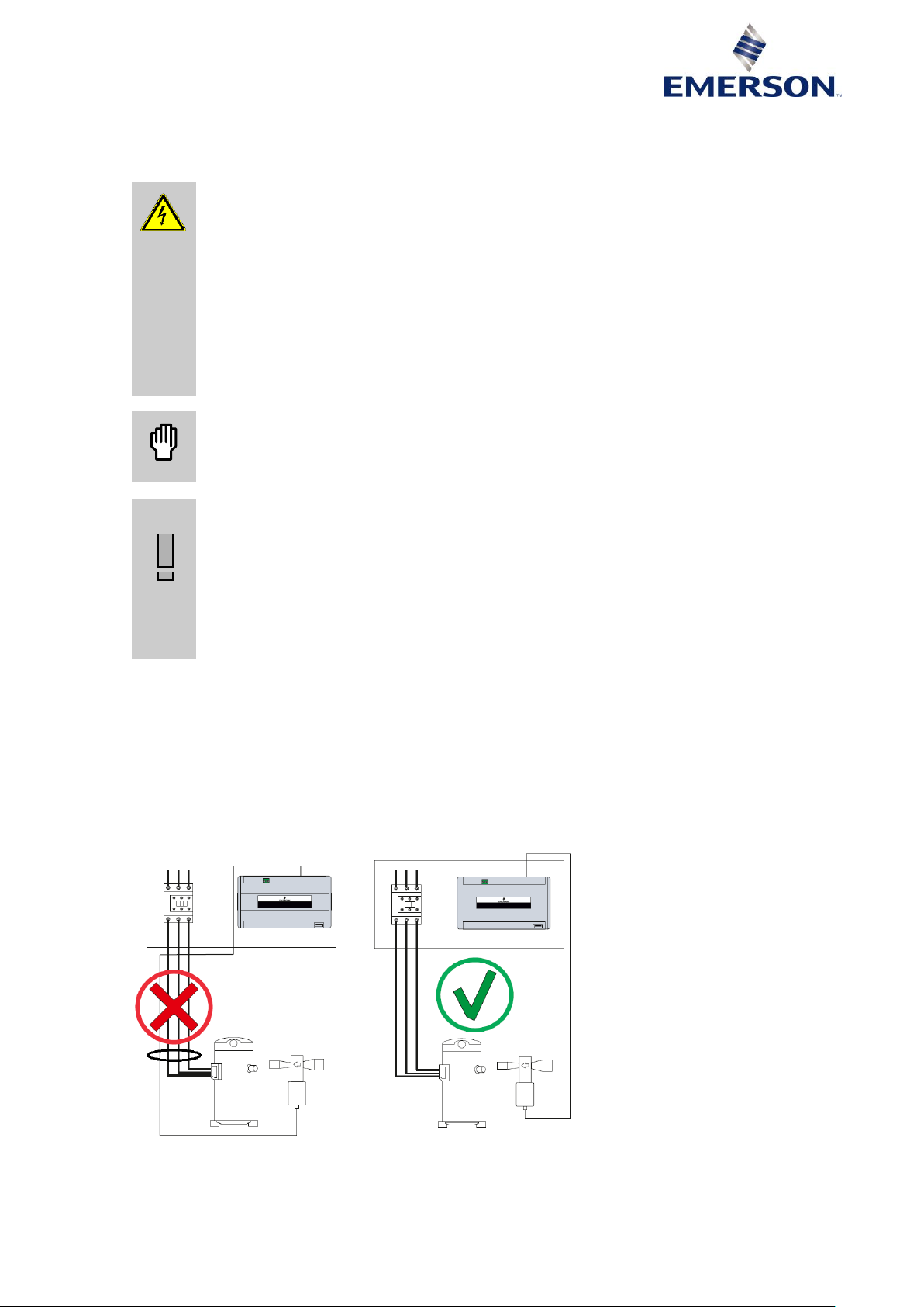
▪ Separate the signal cables from the power cables. It is recommended to follow the diagram in
Figure 13 below as far as possible.
Figure 13: Example of wrong connection
The example in above diagram shows how improper connection can generate a wrong signal to the
EXV valve and the possibility to lose steps.
Page 27

24 AGL_Sol_PEC_02_E_Rev01
7.1.1 EMC
▪ Separate drive-to-compressor supply from controls, sensor lines and communication lines.
▪ Keep a distance of 10 cm between clean and dirty lines and components if possible.
▪ Do not disable EMC measures by:
o wrong mounting of components (position & orientation);
o crossing or bringing together clean and dirty cables or components;
o putting components too close together;
o not keeping enough clearance distance.
Figure 14
7.1.2 Ferrites
▪ Ferrites should be positioned close to input and output of the drive.
▪ Do not pass input and output wires which would make the ferrite useless.
Figure 15: Example of good practice 4 turns with one ferrite
NOTE: For more information, please refer to Application Guidelines AGL_Sol_EV3 "EV3
Inverter Drive for ZPV* Variable Speed Compressors" and AGL_AC_VS_YPV "Copeland
Scroll Variable Speed Compressors for R32 Applications – YPV066* & YPV096*" or contact
your local Application Engineering representative at Emerson.
EV3
VSS
Drive supply
EMC measures,
eg, filter, Ferrites, etc.
VSS supply
screened cable
1 DC choke internal
RCD
type B/B+
Page 28

AGL_Sol_PEC_02_E_Rev01 25
7.1.3 Digital inputs and outputs wiring
Figure 16: Digital inputs and outputs wiring for variable-speed circuit 1 (proposal)
Figure 17: Digital inputs and outputs wiring for fixed-speed circuit 2
PeC
DO8 (FS Scroll #6)
DO7 (FS Scroll #5)
DO6 (FS Scroll #4)
DI4 (Feedback safety)
PeC
Modbus master
DO3 (FS Scroll #6)
DO2 (FS Scroll #5)
DI1 (Feedback safety)
Page 29

26 AGL_Sol_PEC_02_E_Rev01
8 Items list for electronic solution package
Description
Type
Item number
PeC series
PeC C100 (single circuit)
PeC C200 (double circuit)
8418438
8418449
Electronic expansion
valves
EX4 – 7 Bipolar stepper
motor valves, uniflow
EX4-I21
EX5-U21
EX6-M21
800615
800618
800621
Cable connector
assembly
EXV-M60 (6-m cable)
804665
Pressure transmitter
Suction pressure 18 bar
Discharge gas pressure
50 bar
PT5N-18M
PT5N-18T
PT5N-50M
PT5N-50T
(Type: xxM = screwed,
xxT = brazed)
805351
805381
805353
805383
Plugged cable assembly
for pressure sensor
PT4-M15 (1.5-m cable)
PT4-M30 (3-m cable)
PT4-M60 (6-m cable)
804803
804804
804805
Temperature sensor with
TP1 NP3 (3-m cable)
TP1 NP6 (6-m cable)
TP1 NP12 (12-m cable)
804489
804490
804491
Accessories
Connectors kit
PeC C100
PeC C200
807983
807984
PeC – EV3 Drive
Modbus connection
XJ485-USB converter
3185902
PeC Firmware flash
cable
Cable XJ485-USB
converter
8416512
Table 19
Page 30

AGL_Sol_PEC_02_E_Rev01 27
9 Certification & approval
▪ The controllers PeC C100 and C200 comply with the Low Voltage Directive LVD 2014/35/EU.
The applied harmonised standards are:
− EN 60335-1:2012/A11:2014: Household and similar electrical appliances - Safety - Part 1:
Part 1: General requirements;
− EN 60335-2-40:2003/A13:2012: Household and similar electrical appliances - Safety - Part
2-40: Particular requirements for electrical heat pumps, air conditioners and dehumidifiers.
Other applied standards:
− DIN IEC 60335-2-40:2018-05: Household and similar electrical appliances - Safety - Part 240: Particular requirements for electrical heat pumps, air-conditioners and dehumidifiers;
− EN 60079-15:2010: Explosive atmospheres - Part 15: Equipment protection by type of
protection "n".
▪ The controllers PeC C100 and C200 comply with the Electromagnetic Compatibility Directive
EMC 2014/30/EU. The applied harmonised standards are:
− EN 55014-1:2006/A2:2011: Electromagnetic compatibility - Requirements for household
appliances, electric tools and similar apparatus Part 1: Emission;
− EN 55014-2: 1997/A2:2008: Electromagnetic compatibility - Requirements for household
appliances, electric tools and similar apparatus Part 2: Immunity - Product family standard.
Other applied standards:
− DIN EN 55014-1:2018-08: Electromagnetic compatibility - Requirements for household
appliances, electric tools and similar apparatus Part 1: Emission;
− DIN EN 55014-2:2016-01: Electromagnetic compatibility - Requirements for household
appliances, electric tools and similar apparatus Part 2: Immunity - Product family standard.
▪ The controllers PeC C100 and C200 comply with RoHS 2011/65/EU, (EU) 2015/863.
10 Dismantling & disposal
With reference to the Waste Electrical and Electronic Equipment (WEEE)
Directive 2012/19/EU and to the relative national legislation, please note that:
▪ There lies the obligation not to dispose of electrical and electronic
waste as municipal waste but to separate the waste.
▪ Public or private collection points must be used to dispose of the goods in accordance
with local laws. Furthermore, at the end of the product's life, it is also possible to return
this to the retailer when a new purchase is made.
▪ This equipment may contain hazardous substances. Improper use or incorrect disposal
can have adverse effects on human health and the environment.
▪ The symbol shown on the product or the package indicates that the product has been
placed on the market after 13 August 2005 and must be disposed of as separated waste.
▪ Should the product be disposed of incorrectly, sanctions may be applied as stipulated in
applicable local regulations regarding waste disposal.
DISCLAIMER
1. The contents of this publication are presented for informational purposes only and are not to be
construed as warranties or guarantees, express or implied, regarding the products or services
described herein or their use or applicability.
2. Emerson Climate Technologies GmbH and/or its affiliates (collectively "Emerson"), as
applicable, reserve the right to modify the design or specifications of such products at any time
without notice.
3. Emerson does not assume responsibility for the selection, use or maintenance of any product.
Responsibility for proper selection, use and maintenance of any Emerson product remains
solely with the purchaser or end user.
4. Emerson does not assume responsibility for possible typographic errors contained in this
publication.
Page 31

28 AGL_Sol_PEC_02_E_Rev01
Page 32

BENELUX
Josephinastraat 19
NL-6462 EL Kerkrade
Tel: +31 45 535 06 73
Fax: +31 45 535 06 71
benelux.sales@emerson.com
UK & IRELAND
Unit 17, Theale Lakes Business Park
Reading, Berkshire RG7 4GB
Tel: +44 1189 83 80 00
Fax: +44 1189 83 80 01
uk.sales@emerson.com
GERMANY, AUSTRIA & SWITZERLAND
Theo-Mack Str. 3
DE-63477 Maintal
Tel: +49 6109 605 90
Fax: +49 6109 60 59 40
ECTGermany.sales@emerson.com
FRANCE, GREECE & MAGHREB
8, Allée du Moulin Berger
FR-69134 Ecully Cédex, Technoparc - CS 90220
Tel: +33 4 78 66 85 70
Fax: +33 4 78 66 85 71
mediterranean.sales@emerson.com
ITALY
Via Ramazzotti, 26
IT-21047 Saronno (VA)
Tel: +39 02 96 17 81
Fax: +39 02 96 17 88 88
italy.sales@emerson.com
SPAIN & PORTUGAL
C/ Pujades, 51-55 Box 53
ES-08005 Barcelona
Tel: +34 93 412 37 52
iberica.sales@emerson.com
CZECH REPUBLIC
Hajkova 22
CZ - 133 00 Prague
Tel: +420 733 161 651
Fax: +420 271 035 655
Pavel.Sudek@emerson.com
ROMANIA & BULGARIA
Parcul Industrial Tetarom 2
Emerson Nr. 4 400641 Cluj-Napoca
Tel: +40 374 13 23 50
Fax: +40 374 13 28 11
ro-bg.sales@emerson.com
ASIA PACIFIC
Suite 2503-8, 25/F., Exchange Tower
33 Wang Chiu Road, Kowloon Bay
Kowloon , Hong Kong
Tel: +852 2866 3108
Fax: +852 2520 6227
SWEDEN, DENMARK, NORWAY & FINLAND
Pascalstr. 65
DE-52076 Aachen
Tel: +49 2408 929 0
Fax: +49 2408 929 525
nordic.sales@emerson.com
EASTERN EUROPE & TURKEY
Pascalstr. 65
DE-52076 Aachen
Tel: +49 2408 929 0
Fax: +49 2408 929 525
easterneurope.sales@emerson.com
POLAND
Szturmowa 2
PL-02678 Warsaw
Tel: +48 22 458 92 05
Fax: +48 22 458 92 55
poland.sales@emerson.com
RUSSIA & CIS
Dubininskaya 53, bld. 5
RU-115054, Moscow
Tel: +7 - 495 - 995 95 59
Fax: +7 - 495 - 424 88 50
ECT.Holod@emerson.com
BALKAN
Selska cesta 93
HR-10 000 Zagreb
Tel: +385 1 560 38 75
Fax: +385 1 560 38 79
balkan.sales@emerson.com
MIDDLE EAST & AFRICA
PO Box 26382
Jebel Ali Free Zone - South, Dubai - UAE
Tel: +971 4 811 81 00
Fax: +971 4 886 54 65
mea.sales@emerson.com
For more details, see www.climate.emerson.com/en-gb
Connect with us: facebook.com/EmersonCommercialResidentialSolutions
AGL_Sol_PEC_02_E_Rev01
Emerson Commercial & Residential Solutions
Emerson Climate Technologies GmbH - Pascalstrasse 65 - 52076 Aachen, Germany
Tel. +49 (0) 2408 929 0 - Fax: +49 (0) 2408 929 570 - Internet: www.climate.emerson.com/en-gb
The Emerson logo is a trademark and service mark of Emerson Electric Co. Emerson Climate Technologies Inc. is a subsidiary of Emerson Electric Co.
Copeland is a registered trademark and Copeland Scroll is a trademark of Emerson Climate Technologies Inc.. All other trademarks are property of their respective owners.
Emerson Climate Technologies GmbH shall not be liable for errors in the stated capacities, dimensions, etc., as well as typographic errors. Products, specications, designs and
technical data contained in this document are subject to modication by us without prior notice. Illustrations are not binding.
© 2019 Emerson Climate Technologies, Inc.
 Loading...